
PCR-80 - MIDI Controller EDIROL - Free user manual and instructions
Find the device manual for free PCR-80 EDIROL in PDF.
| Product Type | MIDI Controller |
| Brand | EDIROL |
| Model | PCR-80 |
| Keyboard | 61 keys (velocity) |
| Controllers | 8 rotary encoders (R1-R8), 8 buttons (S1-S8), 6 buttons (B1-B6), 3 sliders (L1-L3), 2 wheels (P1, P2), modulation wheel (bender) |
| Connectivity | USB, MIDI In, MIDI Out, expression pedal jack |
| Power | Included AC adapter or USB bus power |
| Operating Modes | PLAY, MIDI CH, Program Change, Bank, Memory, Snapshot, Panic, Edit |
| Keyboard Functions | Octave Shift (-4 to +5), Transpose (-12 to +12) |
| Memory | 16 internal memories (GM2 default) |
| Supported Operating Systems | Windows XP, 2000, Me, 98; Mac OS (OMS/FreeMIDI) |
| Included Accessories | USB cable, AC adapter, CD-ROM with drivers |
| Safety | Protection circuit; respect power-on sequence |
| Maintenance and Cleaning | Clean with a dry, soft cloth; avoid solvents and abrasive products |
| Expression Pedal | Use only EV-5 pedal (optional) |
| Specificities | Panic function to stop stuck notes; Snapshot mode to capture controller state |
Frequently Asked Questions - PCR-80 EDIROL
User questions about PCR-80 EDIROL
0 question about this device. Answer the ones you know or ask your own.
Ask a new question about this device
Download the instructions for your MIDI Controller in PDF format for free! Find your manual PCR-80 - EDIROL and take your electronic device back in hand. On this page are published all the documents necessary for the use of your device. PCR-80 by EDIROL.
USER MANUAL PCR-80 EDIROL
Thank you for purchasing the PCR-30/50/80 USB MIDI controller.
Before using this unit, carefully read the sections entitled: "USING THE UNIT SAFELY" and "IMPORTANT NOTES". These sections provide important information concerning the proper operation of the unit. Additionally, in order to feel assured that you have gained a good grasp of every feature provided by your new unit, Owner's manual should be read in its entirety. The manual should be saved and kept on hand as a convenient reference.
IMPORTANT NOTES
In addition to the items listed under "USING THE UNIT SAFELY" on page 2 -3, please read and observe the following:
Power Supply
- Do not use this unit on the same power circuit with any device that will generate line noise (such as an electric motor or variable lighting system).
- The AC adaptor will begin to generate heat after long hours of consecutive use. This is normal, and is not a cause for concern.
- Before connecting this unit to other devices, turn off the power to all units. This will help prevent malfunctions and/or damage to speakers or other devices.
Placement
- This device may interfere with radio and television reception. Do not use this device in the vicinity of such receivers.
- Noise may be produced if wireless communications devices, such as cell phones, are operated in the vicinity of this unit. Such noise could occur when receiving or initiating a call, or while conversing. Should you experience such problems, you should relocate such wireless devices so they are at a greater distance from this unit, or switch them off.
- Do not expose the unit to direct sunlight, place it near devices that radiate heat, leave it inside an enclosed vehicle, or otherwise subject it to temperature extremes. Excessive heat can deform or discolor the unit.
- When moved from one location to another where the temperature and/or humidity is very different, water droplets (condensation) may form inside the unit. Damage or malfunction may result if you attempt to use the unit in this condition. Therefore, before using the unit, you must allow it to stand for several hours, until the condensation has completely evaporated.
- Do not allow objects to remain on top of the keyboard. This can be the cause of malfunction, such as keys ceasing to produce sound.
Handling CD-ROMs
- Avoid touching or scratching the shiny underside (encoded surface) of the disc. Damaged or dirty CD-ROM discs may not be read properly. Keep your discs clean using a commercially available CD cleaner.
Maintenance
- For everyday cleaning wipe the unit with a soft, dry cloth or one that has been slightly dampened with water. To remove stubborn dirt, use a cloth impregnated with a mild, non-abrasive detergent. Afterwards, be sure to wipe the unit thoroughly with a soft, dry cloth.
- Never use benzine, thinners, alcohol or solvents of any kind, to avoid the possibility of discoloration and/or deformation.
Additional Precautions
- Please be aware that the contents of memory can be irretrievably lost as a result of a malfunction, or the improper operation of the unit. To protect yourself against the risk of loosing important data, we recommend that you periodically save a backup copy of important data you have stored in the unit's memory in another MIDI device (e.g., a sequencer).
- Unfortunately, it may be impossible to restore the contents of data that was stored in another MIDI device (e.g., a sequencer) once it has been lost. Roland Corporation assumes no liability concerning such loss of data.
- Use a reasonable amount of care when using the unit's buttons, sliders, or other controls; and when using its jacks and connectors. Rough handling can lead to malfunctions.
- When connecting / disconnecting all cables, grasp the connector itself—never pull on the cable. This way you will avoid causing shorts, or damage to the cable's internal elements.
- To avoid disturbing your neighbors, try to keep the unit's volume at reasonable levels (especially when it is late at night).
- When you need to transport the unit, package it in the box (including padding) that it came in, if possible. Otherwise, you will need to use equivalent packaging materials.
- Use only the specified expression pedal (EV-5; sold separately). By connecting any other expression pedals, you risk causing malfunction and/or damage to the unit.
Table des matieres
IMPORTANT NOTES. 4
Table des matieres 5
Contents of the package 11
Names of things and what they do 12
Panel. 12
Rear Panel 14
Installation 15
Mode Bank (BANK). 40
Mode Memoire (MEMORY) 41
Mode Instantané (SNAPSHOT) 42
Edit mode (EDIT). 45
Controller settings. 46
NOTE ASSIGN 47
AFTEROUCH ASSIGN 49
CONTROL CHANGE ASSIGN 52
PROGRAM CHANGE ASSIGN 55
RPN/NRPN ASSIGN 58
SYS EX. ASSIGN 60
TEMPO ASSIGN 66
NO ASSIGN 66
ASSIGN COPY 67
SAVE 68
OMNI. 69
PROTECT 70
BULK. 71
Receive mode. 71
Transmit mode 73
SYSTEM. 74
Setting method A 75
Setting method B. 75
Setting method C. 75
Setting method D 76
Setting method E. 76
Setting method F. 76
Appendixes 77
Convenient functions 78
Setting the input mode 78
Specifying the button mode 78
Specifying the port 79
Sys Ex. ASSIGN items 80
Specifying the checksum 80
Specifying the location of the data 81
Inputting channel/block data 82
V-LINK mode 83
Memory sets 84
GM2 set (MEMORY: 0). 84
MCR-8 MODE 3(SONAR 2) SET .85
MCR-8 MODE 4(Cubase 5/SX) SET .86
H-COMPATIBLE (ProTools LE, Digital Performer) SET (MEMORY: 9).87
GS SET 87
XG SET 89
Troubleshooting 90
Problems related to the USB driver 90
Cannot install the driver correctly. 90
PCR-30/50/80 is not detected when making OMS or FreeMIDI settings....91
"Find new hardware wizard" does not execute automatically 91
The "Insert Disk" dialog box does not appear 91
"Find new hardware wizard" ends before the process is completed 91
"Found unknown device" appears even though you installed the driver.....92
An "Unknown driver found" dialog box appears, and you are unable to install the driver. 92
Device Manager shows "?","!”, or "USB Composite Device". 92
Driver is not installed correctly 92
Can't install/delete/use the driver in Windows XP/2000 92
Windows XP/2000 displays a "Hardware Installation" or "Digital Signature Not Found" dialog box 92
Deleting the driver. 93
Windows users 93
Macintosh users. 93
MIDI implementation 94
Main specifications 99
PCR-30/50/80: MIDI KEYBOARD CONTROLLER. 99
INDEX 101
- Microsoft and Windows are registered trademarks of Microsoft Corporation.
- Windows® 98 is known officially as: "Microsoft® Windows® 98 operating system".
- Screen shots in this documents are reprinted with permission from Microsoft Corporation.
- Windows® 2000 is known officially as: "Microsoft® Windows® 2000 operating system".
- Windows® Me is known officially as: "Microsoft® Windows® Millennium Edition operating system".
- Windows® XP is known officially as: "Microsoft® Windows® XP operating system".
- Apple and Macintosh are registered trademark of Apple Computer, Inc.
- MacOS is a trademark of Apple Computer, Inc.
- All product names mentioned in this document are trademarks or registered trademarks of their respective owners.
- OMS is a registered trademark of Opcode Systems, Inc.
- FreeMIDI is a trademark of Mark of the Unicorn, Inc.
Contents of the package
The PCR-30/50/80 includes the following items. When you open the package, first make sure that all items are included. If any are missing, contact the dealer where you purchased the PCR-30/50/80.
●MIDI Keyboard Controller
PCR-30/50/80

*This figure is the PCR-30.
AC adaptor
This is the only AC adaptor you should use with the PCR-30/50/80. Do not use any AC adaptor other than the supplied one, since doing so may cause malfunction.
USB cable
Use this to connect the USB connector of your computer with the USB connector of the PCR-30/50/80. For details on connections and driver installation, refer to Installation (p. 15).
- Please use only the included USB cable. If you require a replacement due to loss or damage, please contact a "EDIROL/Roland Service Center" listed in the "Information" section at the end of this manual.
-CD-ROM
This contains drivers and editors for use with the PCR-30/50/80.
- Template sheets (two sheets)
One of these templates lists the messages that are assigned to the knobs and sliders (controllers) by GM2 memory (memory no. 0). A blank sheet is also included for you to make a note of your own controller settings.
Owner's Manual
This is the manual you are reading. Please keep it on hand for reference.
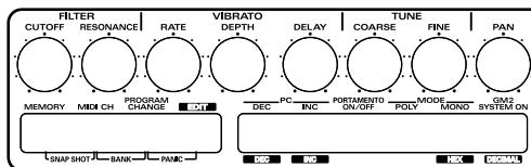
Names of things and what they do
Panel
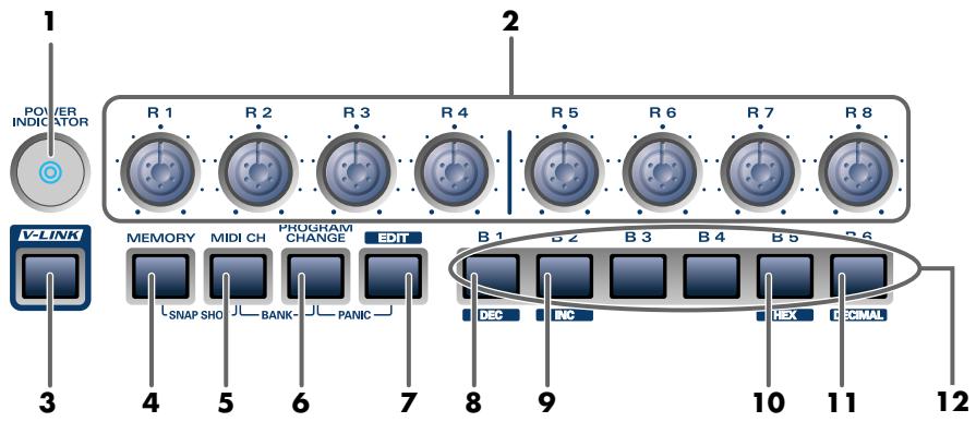
- Power Indicator
Lights when the power is on.
- Controllers [R1]-[R8]
You can assign MIDI messages to these controllers.
- V-LINK Button
Press the V-LINK button to enter V-LINK mode (p. 83). When V-LINK mode is on, the V-LINK button will light.
V-LINK
V-LINK ( V-LINK ) is a function that lets you play music and images. By using this with a V-LINK compatible video device, you can enjoy various video effects that are linked to your performance.
- MEMORY Button
Accesses memories that are stored within the PCR-30/50/80.
- MIDI CH Button
Specifies the transmission channel ("current channel") for the keyboard and bender.
- PROGRAM CHANGE Button
Transmits program change messages on the current channel.
7.EDITButton
Used to assign MIDI messages to the controllers.
- DEC Button
Decreases the value of a setting by one (except in PLAY mode (p. 36)).
- INC Button
Increases the value of a setting by one (except in PLAY mode (p. 36)).
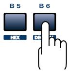
- HEX Button
When not in PLAY mode, sets the input mode to hexadecimal (HEX input mode).
11. DECIMAL Button
When not in PLAY mode, sets the input mode to decimal (DECIMAL input mode).
12. Controllers [B1]-[B6]
You can assign MIDI messages to these controllers.
![EDIROL PCR-80 - Controllers [B1]-[B6] - 1](/content/2024/12/174374/images/9e43fd1a91f78194303dcb29d36612a73693e41e63ad3fe03693c340dd979cbf.jpg)
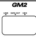
13.Display
Indicates the current status and various other information.
| USB | Lights if the PCR-30/50/80 is connected to your computer via USB. |
| DATA OUT | This will blink when MIDI messages are transmitted via USB or MIDI OUT. |
| HEX | Lights when the value shown in the display is hexadecimal. |
14. Controllers [S1]-[S8]
You can assign MIDI messages to these controllers.
![EDIROL PCR-80 - Controllers [S1]-[S8] - 1](/content/2024/12/174374/images/cde4bee69ddd970c2c5d14363024503be2af84e37ef23059b25bbe0b9c838148.jpg)
15.Controllers [L1]-[L3]
You can assign MIDI messages to these controllers.
16.TRANSPOSE/ENTER Button
Use [TRANSPOSE] + [OCTAVE -/+] to transpose the pitch of the keyboard in semitone steps. Also, in any mode except PLAY mode, it functions as the [ENTER] button, which you need to press to confirm the settings you've made.
17.OCTAVE-/+
Press [OCTAVE -/+] to shift the pitch of the keyboard up or down in steps of an octave. When not in PLAY mode, use these buttons to return to the previous setting item (the [BACK] button) or to cancel the setting and return to PLAY mode (the [CANCEL] button).
18.BENDER Lever
This lever can be used to modify the pitch or apply vibrato.
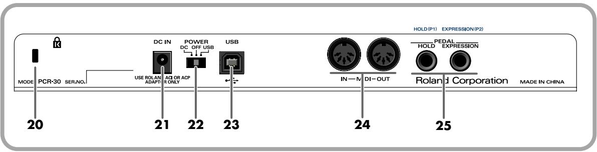
20. Security Slot (R)
A commercially available security lock can be attached here.
http://www.kensington.com/
21.AC adaptor jack
Connect the include AC adaptor to this jack. Insert the plug firmly so it won't get unplugged accidentally.
22. Power switch
| DC | Power on using the AC adaptor |
| OFF | Power is off |
| USB *1 | Power on using a USB cable (when not using the AC adaptor) |
*1 Bus power (USB)
BUS power can be used when the PCR-30/50/80 is connected to your computer via a USB cable. In this case, the power will be supplied from your computer via the USB cable. To use the PCR-30/50/80 with bus power, set the power switch to USB.
- For some computers, the PCR-30/50/80 may not operate if bus power is used. In this case, use the included AC adaptor.
23. USB connector
Use this when connecting the PCR-30/50/80 to your computer via a USB cable.
24. MIDI IN/OUT connectors
These can be connected to the MIDI connectors of other MIDI devices to transmit and receive MIDI messages.
25. Controller [P1] and [P2]
You can connect the appropriate type of pedals to these jacks and use them as controllers.
| HOLD | Connect a pedal switch to this jack and use it as a Hold pedal. |
| EXPRESSION | Connect an expression pedal to this jack and use it to control tone or volume in real time. |
You can also assign MIDI messages to these controllers as desired.
Installation
"Driver required for USB device 'unknown device' is not available. Search for driver on the Internet?" Cliquez sur [Cancel].
"Software required for using device 'unknown device' cannot be found. Please refer to the manual included with the device, and install the necessary software"
This installation requires your computer to restart after installing this software. Click Continue to automatically quit all other running applications. Click Cancel to leave your disks untouched.
Cancel
Continue

AppleTalk is on. It is used for connecting your computer to network services, such as file servers and printers. But it can make MTDI communication less reliable.
If you choose Turn It Off, don't disconnect AppleTalk yet.
CAUTION: OMS may not turn off AppleTalk as reliably as Apple's system software.
Options..
Leave It On
Turn It Off

A diamond mark () indicate in the settings are enabled.
10
Press the [EDIT] button to enter Edit mode. In Edit mode you can make the following settings.


| Selected item | Display | Refer to | Description |
| [R1--R8][S1--S8][B1--B6][L1--L3][P1, P2] | Indicates the number of the selected controller | “Controller settings”(p. 46) | Assign a desired MIDI message to the controller. |
| Keyboard [BULK] | BLA | “BULK” (p. 71) | Transmit or receive the contents of a memory set as bulk data. |
| Keyboard [SYSTEM] | 540 | “SYSTEM” (p. 74) | Make system settings for the PCR. |
| Keyboard [SAVE] | SAU | “SAVE” (p. 68) | Save the current memory settings into a memory. |
| Keyboard [OMNI] | OII | “OMNI” (p. 69) | Specify whether the output channel and output port for messages will follow the setting of the controller or the system setting. |
| Keyboard [PROTECT] | PBC | “PROTECT” (p. 70) | Specify whether ALL BULK reception and SAVE operations will be prohibited. |
For details, refer to the explanation of how to set each item.
Controller settings
You can assign the following functions to a controller.
- After you have modified the controller settings, perform the "SAVE" (p. 68) operation as needed. If you turn off the power without executing "SAVE", your changes will be lost.
| NOTE | “NOTE ASSIGN” (p. 47) | |
| AFTERTOUCH | “AFTERTOUCH ASSIGN” (p. 49) | |
| CONTROL CHANGE | “CONTROL CHANGE ASSIGN” (p. 52) | |
| PROGRAM CHANGE | “PROGRAM CHANGE ASSIGN” (p. 55) | |
| RPN | “RPN/NRPN ASSIGN” (p. 58) | |
| NRPN | “RPN/NRPN ASSIGN” (p. 58) | |
| SYSTEM Ex. | “SYS EX. ASSIGN” (p. 60) | |
| TEMPO | “TEMPO ASSIGN” (p. 66) | |
| NO ASSIGN | “NO ASSIGN” (p. 66) |
A Copy function is also available. For the procedure, refer to "ASSIGN COPY" (p. 67).
- For NOTE, AFTERTOUCH, CONTROL CHANGE, PROGRAM CHANGE, RPN, NRPN, and SYSTEM Ex., the rightmost digit (third place) in the display is a number that indicates the mode (Basic mode or Advanced mode).
- If you want to assign a single-byte system message (system realtime message, tune request) or a freely specified message of up to 24 bytes, refer to "SYS EX. ASSIGN" (p. 60).
How Basic mode and Advanced mode differ
Each assignment can be made either in Basic mode or Advanced mode.
Use the mode that is appropriate for your purpose.
Basic mode
You can make assignments easily, with the minimum number of steps.
Advanced mode
A greater number of steps are required, but you can specify more parameters and make more sophisticated assignments.
NOTE ASSIGN
Here's how to assign a Note message to a controller. In addition to being used to play sounds, note messages can also be used to control a sequencer.
| Mode | Keyboard | Velocity | Port |
| Basic mode | 0 | 100 (64H) | PCR 1 |
| Advanced mode | 1 | Assignable | Assignable |
Basic mode
1
Press the [EDIT] button.
The display will indicate "EDT".

2
Slightly move the controller to which you want to assign a Note message. In the case of a button, press that button.

The display will indicate the number of the selected controller.
3
Verify that the display shows the correct controller number, and press the [ENTER] button.
4
Press the [NOTE] key.

The display will indicate "NT0".
5
Press the [ENTER] button.

The display will indicate "C--".
*1 Reference
6
Input the channel. Use the [DEC][INC] buttons or the [0]-[F] keys to specify the channel.
7
Press the [ENTER] button.

The display will indicate "N--".
*1 Reference
8
Input the note number. Use the [DEC][INC] buttons or the [0]-[F] keys to specify the note number.
9
Press the [ENTER] button.
10
If you are making an assignment for a button, specify the button mode. ( "Specifying the button mode" (p. 78))
Advanced mode
Advanced mode 1 of NOTE ASSIGN lets you specify the velocity value in addition to the items of Basic mode.
- Press the [EDIT] button.
- Slightly move the controller to which you want to assign a Note message. In the case of a button, press that button.
The display will indicate the number of the selected controller.
- Verify that the display indicates the correct controller, and press the [ENTER] button.
- Press the [NOTE] key and then press key [1].
The display will indicate "NT1".
- Press the [ENTER] button.
- Input the channel.
- Press the [ENTER] button.
- Input the note number.
- Press the [ENTER] button.
The display will indicate "V--".
*1 Reference

- Input the velocity.
- Press the [ENTER] button.
The display will indicate "P--".
*1 Reference

- Specify the output port. ( "Specifying the port" (p. 79))
- If you are making an assignment for a button, specify the button mode.
( "Specifying the button mode" (p. 78))
- If you set [S1--S8], [R1--R8], or [P2] to NOTE ASSIGN, setting the controller to the maximum position will transmit the specified velocity value. Setting the controller to the minimum position will transmit a note message with a velocity of 0.
- If you assign this to [B1--B6] or [P1], the specified velocity value will be transmitted when you turn the controller on. When you turn the controller off, a note message with a velocity value of 0 will be transmitted.
■ AFTERTOUCH ASSIGN
Here's how to assign an Aftertouch message to a controller.
| Mode | Keyboard | Message | Value range | Port |
| Basic mode | 0 | Channel Pressure | 00-7FH | Port 1 |
| Advanced mode 1 | 1 | Channel Pressure | Assignable | Assignable |
| Advanced mode 2 | 2 | Polyphonic Key Pressure | 00-7FH | Port 1 |
| Advanced mode 3 | 3 | Polyphonic Key Pressure | Assignable | Assignable |
Basic mode
1
Press the [EDIT] button.
The display will indicate "EDT".

2
Slightly move the controller to which you want to assign an Aftertouch message. In the case of a button, press that button.
The display will indicate the number of the selected controller.

3
Verify that the display shows the correct controller number, and press the [ENTER] button.
4
Press the [AFTERTOUCH] key.
The display will indicate "AT0".

5
Verify that the display is correct, and press the [ENTER] button.
The display will indicate "C--".
*1 Reference

6
Input the channel. Use the [DEC][INC] buttons or the [0]-[F] keys to specify the channel.
7
Press the [ENTER] button.
8
If you are making an assignment for a button, specify the button mode. () "Specifying the button mode" (p. 78))
Advanced mode 1-3
Advanced mode 1 of AFTERTOUCH ASSIGN lets you specify the upper and lower limits of the aftertouch value in addition to the items of Basic mode. Advanced modes 2 and 3 let you specify an aftertouch message for an individual note (Polyphonic Key Pressure) instead of specifying the channel.
- Press the [EDIT] button.
- Slightly move the controller to which you want to assign an Aftertouch message. In the case of a button, press that button.
The display will indicate the number of the selected controller.
- Verify that the display indicates the correct controller, and press the [ENTER] button.
- Press the [AFTERTOUCH] key and then press a key [1]-[3].
The display will indicate the selected mode.
- Press the [ENTER] button.
- Input the channel.
- Press the [ENTER] button.
- If you are using Advanced modes 2 or 3, input the note number.
- If you are using Advanced modes 2 or 3, Press the [ENTER] button.
- If you are using Advanced modes 1 or 3, specify the upper limit and lower limit of the value as described in "Aftertouch Assign upper/ lower limit and port settings" (p. 51), and specify the output port.
- If you are making an assignment for a button, specify the button mode.
() "Specifying the button mode" (p. 78))

Aftertouch Assign upper/ lower limit and port settings
In the case of Aftertouch Assign 1 or 3, you can set the upper limit and lower limit of the value, and specify the port.
- The following display will appear.
*1 Reference

- Use the [DEC][INC] buttons or the [0]-[F] keys to specify the upper limit.
- Press the [ENTER] button.
The following display will appear.

*1 Reference
- Use the [DEC][INC] buttons or the [0]-[F] keys to specify the lower limit.
- Press the [ENTER] button.
The display will indicate "P--".
*1 Reference

- Specify the output port. ( "Specifying the port" (p. 79))
■ CONTROL CHANGE ASSIGN
Here's how to assign a control change message to a controller.
| Mode | keyboard | Value range | Port |
| Basic mode | 0 | 00-7FH | PCR 1 |
| Advanced mode 1 | 1 | Assignable | Assignable |
| Advanced mode 2 | 2 | Simulates a rotary encoder | Assignable |
Basic mode
1
Press the [EDIT] button.
The display will indicate "EDT".

2
Slightly move the controller to which you want to assign a Control Change message. In the case of a button, press that button.
The display will indicate the number of the selected controller.
3
Confirm what's indicated, and press the [ENTER] button.

4
Press the [CONTROL CHANGE] key.
The display will indicate "CC0".

5
Confirm what's indicated, and press the [ENTER] button.
The display will indicate "C--".
*1 Reference

6
Input the channel. Use the [DEC][INC] buttons or the [0]-[F] keys to specify the channel.
7
Press the [ENTER] button.
The display will indicate "N--".
*1 Reference

8
Use the [DEC][INC] buttons or the [0]-[F] keys to specify the control change number.
9
Press the [ENTER] button.
10
If you are making an assignment for a button, specify the button mode. ( "Specifying the button mode" (p. 78))
Advanced mode 1
Advanced mode 1 of CONTROL CHANGE ASSIGN lets you specify the upper and lower limits of the control change value in addition to the items of Basic mode.
- Press the [EDIT] button.
- Slightly move the controller to which you want to assign a Control Change message. In the case of a button, press that button.
The display will indicate the number of the selected controller.
- Confirm what's indicated, and press the [ENTER] button.
- Press the [CONTROL CHANGE] key and then press key [1].
The display will indicate "CC1".
- Press the [ENTER] button.
- Input the channel.
- Press the [ENTER] button.
- Input the control change number.
- Press the [ENTER] button.
- The following display will appear.

*1 Reference
- Use the [DEC][INC] buttons or the [0]-[F] keys to specify the upper limit value.
- Press the [ENTER] button.
- The following display will appear.

*1 Reference
- Use the [DEC][INC] buttons or the [0]-[F] keys to specify the lower limit value.
- Press the [ENTER] button.
- The display will indicate "P--".

*1 Reference
- Specify the output port. () "Specifying the port" (p. 79))
- If you are making an assignment for a button, specify the button mode. ( "Specifying the button mode" (p. 78))
Advanced mode 2
Advanced mode 2 simulates the operation of a conventional rotary encoder. If this is assigned to a controller, moving that controller toward the right (upward) of center will have the same effect as turning the encoder clockwise, and moving the controller toward the left (downward) of center will have the same effect as turning the encoder counterclockwise. As the controller is moved further away from the center, the result will be the same as if the rotary encoder were moved more quickly. You can assign advanced mode 2 to a button, but it will not function.
- Press the [EDIT] button.
- Slightly move the controller to which you want to assign a Control Change message. The display will indicate the number of the selected controller.
- Confirm what's indicated, and press the [ENTER] button.
- Press the [CONTROL CHANGE] key and then press key [2]. The display will indicate "CC2".
- Press the [ENTER] button.
- Input the channel.
- Press the [ENTER] button.
- Input the control change number. Use the [DEC][INC] buttons or the [0]-[F] keys to specify the control change number.
- Press the [ENTER] button.
- The display will indicate "P--".
*1 Reference

- Specify the output port. ( "Specifying the port" (p. 79))
■ PROGRAM CHANGE ASSIGN
Here's how to assign a program change message to a controller.
| Mode | Number | Effect | Bank | Port |
| Basic mode | 0 | Fixed value | Not output | PCR 1 |
| Advanced mode 1 | 1 | Assignable range of values | Not output | PCR 1 |
| Advanced mode 2 | 2 | Fixed value | Output | Assignable |
| Advanced mode 3 | 3 | PC DEC | Not output | KEYBOARD PORT (p. 74) |
| Advanced mode 4 | 4 | PC INC | Not output | KEYBOARD PORT (p. 74) |
Basic mode
1
Press the [EDIT] button.
The display will indicate "EDT".

2
Slightly move the controller to which you want to assign a Program Change message. In the case of a button, press that button.
The display will indicate the number of the selected controller.
3
Confirm what's indicated, and press the [ENTER] button.

4
Press the [PROGRAM CHANGE] key.
The display will indicate "PC0".

5
Confirm what's indicated, and press the [ENTER] button.
The display will indicate "C--".
*1 Reference

6
Input the channel. Use the [DEC][INC] buttons or the [0]-[F] keys to specify the channel.
7
Press the [ENTER] button.
The display will indicate "N--".
*1 Reference

8
Use the [DEC][INC] buttons or the [0]–[F] keys to specify the program change number.
9
Press the [ENTER] button.
- If you assign Basic mode to [S1--S8], [R1--R8], or [P2], moving the controller from the minimum to the maximum position will transmit the assigned control change messages.
Advance mode 1, 2
Advanced mode 1 of PROGRAM CHANGE ASSIGN lets you specify the upper and lower limits of the program change value. Advanced mode 2 lets you transmit BANK LSB/MSB settings in addition to the program change.
- Press the [EDIT] button.
- Slightly move the controller to which you want to assign a Program Change message. In the case of a button, press that button. The display will indicate the number of the selected controller.
- Confirm what's indicated, and press the [ENTER] button.
Advanced mode 1 —Specifying the range of values
- Press the [PROGRAM CHANGE] key and then press key [1].
- Press the [ENTER] button.
- Input the channel.
- Press the [ENTER] button.
- The following display will appear.

*1 Reference
- Use the [DEC][INC] buttons or the [0]-[F] keys to specify the upper value limit.
- Press the [ENTER] button.
- The following display will appear.
*1 Reference
- Use the [DEC][INC] buttons or the [0]-[F] keys to specify the lower value limit.
- Press the [ENTER] button.
Advanced mode 2 —Transmitting bank data
- Press the [PROGRAM CHANGE] key and then press key [2].
- Press the [ENTER] button.
- Input the channel.
- Press the [ENTER] button.
- Specify the bank select MSB (CC#00). Use the [DEC][INC] buttons or the [0]-[F] keys to specify the MSB.

*1 Reference
- Press the [ENTER] button.
- Specify the bank select LSB (CC#32). Use the [DEC][INC] buttons or the [O]-[F] keys to specify the LSB.

*1 Reference
- Press the [ENTER] button.
- Input the program change number.
- Press the [ENTER] button.
- The display will indicate "P--".

*1 Reference
- Specify the output port. () "Specifying the port" (p. 79))
Advanced modes 3 and 4
Advanced mode 3 lets you assign the Program Change Decrement function (PC DEC) to a controller.
Advanced mode 4 lets you assign the Program Change Increment function (PC INC) to a controller.
- Press the [EDIT] button.
- Slightly move the controller to which you want to assign Program Change DEC/INC. In the case of a button, press that button. The display will indicate the number of the selected controller.
- Confirm what's indicated, and press the [ENTER] button.
- Press the [PROGRAM CHANGE] key and then press key [3] or [4].
- Press the [ENTER] button.
Program Change Decrement function (PC DEC)
This transmits a program change that is one less than the previously transmitted program change number.
Program Change Increment function (PC INC)
This transmits a program change that is one greater than the previously transmitted program change number.
The PC DEC or PC INC is transmitted on the current channel, just as in "Mode Program Change (PROGRAM CHANGE)" (p. 39). The value that is actually transmitted will appear in the display.
- In the explanation here, the "previously transmitted program number" refers to the one that was last transmitted by Advanced Mode 3 or 4 or in "Mode Program Change (PROGRAM CHANGE)" (p. 39).
- Program changes transmitted by basic mode or advanced modes 1 and 2 will not affect the increment/ decrement functions.
RPN/NRPN ASSIGN
Here's how you can assign an RPN or NRPN message to a controller.
| Mode | Keyboard | Data entry MSB (CC#6) range | Data entry LSB (CC#38) range | Port |
| Basic mode | 0 | 00-7FH | Not transmitted | PCR 1 |
| Advanced mode 1 | 1 | Assignable | 00-7FH | Assignable |
1
Press the [EDIT] button.
The display will indicate "EDT".

2
Slightly move the controller to which you want to assign an RPN or NRPN message. In the case of a button, press that button.
The display will indicate the number of the selected controller.
3
Confirm what's indicated, and press the [ENTER] button.

4
Press the [RPN] key.
The display will indicate "RP0".

- If you want to assign an NRPN message, press the [NRPN] key. The following procedure is the same as for RPN.

5
Confirm what's indicated, and press the [ENTER] button.
The display will blink "C--".
*1 Reference

6
Input the channel. Use the [DEC][INC] buttons or the [0]-[F] keys to specify the channel.
7
Press the [ENTER] button.
8
Use the [DEC][INC] buttons or the [0]-[F] keys to specify the RPN MSB (CC#101) or NRPN MSB (CC#99). *1 Reference

9
Press the [ENTER] button.
10 Use the [DEC][INC] buttons or the [O]-[F] keys to specify the RPN LSB (CC#100) or NRPN LSB (CC#98).
*1 Reference

11 Press the [ENTER] button.
12 If you are making an assignment for a button, specify the button mode. () "Specifying the button mode" (p. 78))
Advanced mode
In Advanced mode for RPN/NRPN, you can specify the upper and lower limit of the data entry MSB (CC#6) value when the RPN/NRPN message is transmitted, as well as the various settings available in Basic mode.
- Press the [EDIT] button.
- Slightly move the controller to which you want to assign the RPN or NRPN message. In the case of a button, press that button. The display will indicate the number of the selected controller.
- Confirm what's indicated, and press the [ENTER] button.
-
Press the [RPN] key and then press key [1].
-
If you want to assign an NRPN message, press the [NRPN] key. The following procedure is the same as for RPN.
- Press the [ENTER] button.
- Input the channel. Use the [DEC][INC] buttons or the [0]-[F] keys to specify the channel.
- Press the [ENTER] button.
- Use the [DEC][INC] buttons or the [0]-[F] keys to specify the RPN MSB (CC#101) or NRPN MSB (CC#99).
- Press the [ENTER] button.
-
Use the [DEC][INC] buttons or the [0]-[F] keys to specify the RPN LSB (CC#100) or NRPN LSB (CC#98).
-
Press the [ENTER] button.
- The following display will appear.

*1 Reference
- Use the [0]–[F] keys to specify the upper limit of the data entry MSB (CC#6) value.
- Press the [ENTER] button.
- The following display will appear.

*1 Reference
- Use the [0]–[F] keys to specify the lower limit of the data entry MSB (CC#6) value.
- Press the [ENTER] button.
- The display will indicate "P--".

*1 Reference
- Specify the output port. () "Specifying the port" (p. 79))
- If you are making an assignment for a button, specify the button mode. ( "Specifying the button mode" (p. 78))
■ SYS EX. ASSIGN
Here's how you can assign a system exclusive message to a controller. Advanced mode 2 lets you assign a single-byte system message (System realtime message, tune request).
Advanced modes 3 and 4 let you assign any desired message.(Input up to 24 bytes)
| Mode number | Key-board | Mode | Value range | Required ending | Notes/restrictions |
| Basic mode | 0 | Sys Ex. message | Default range | Input F7 | 1st byte fixed at F0 |
| Advanced mode 1 | 1 | Sys Ex. message | Assignable | Input F7 | 1st byte fixed at F0 |
| Advanced mode 2 | 2 | Single byte system message | - | - | [0-5, 7, 9, D, E][DATA][CHECKSUM] buttons are invalid |
| Advanced mode 3 | 3 | Any desired MIDI message | Default range | Specified number of bytes | [CHECKSUM] button is invalid |
| Advanced mode 4 | 4 | Any desired MIDI message | Assignable | Specified number of bytes | [CHECKSUM] button is invalid |
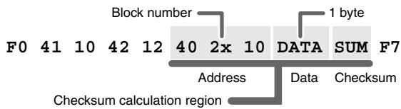
SYS EX. ASSIGN can calculate the checksum automatically, and lets you specify a variable (data) range or embed a channel/block number within the message. ("Sys Ex. ASSIGN items" (p. 80)) In SYS EX. ASSIGN, the input mode will be HEX mode.
1
Press the [EDIT] button.
The display will indicate "EDT".

2
Slightly move the controller to which you want to assign the system exclusive message. In the case of a button, press that button.
The display will indicate the number of the selected controller.
3
Confirm what's indicated, and press the [ENTER] button.

4
Press the [SYSTEM Ex.] key.
5
If you want to select an Advanced mode, press a key from [1] to [4].
The selected mode will blink in the display.

6
Confirm what's indicated, and press the [ENTER] button.
For Basic mode or Advanced mode 1
The display will blink "F0", which is the first byte (starting status byte) of a system exclusive message. (This cannot be changed.)

7
Confirm what's indicated, and press the [ENTER] button.
8
Use the [0]-[F] keys to input the second byte.
9
Press the [ENTER] button.
10 Input the third and subsequent bytes in the same way.
When you have finished inputting the message, use the keyboard to enter [F] and [7], specifying the ending status byte "F7".
12 Press the [ENTER] button.
13 Specify the output port. ( "Specifying the port" (p. 79))
14 If you are making an assignment for a button, specify the button mode. () "Specifying the button mode" (p. 78))
For Advanced mode 2
The display will indicate "F-".
7 Use the [6], [8], [A]–[C], [F] keys to specify the system message.
Press the [ENTER] button.
9 Specify the output port. ( "Specifying the port" (p. 79))

For Advanced modes 3 or 4
The display will indicate "L--".
7 Use the [0]–[F] keys of the keyboard to specify the number (decimal) of bytes you want to input.

*1 Reference
Press the [ENTER] button.
9 Use the [0]-[F] keys to input the first byte.
10 Press the [ENTER] button.
11 Input the second and subsequent bytes in the same way.
12 After you have input the number of bytes you specified in step 7, the PCR-30/50/80 will check whether the messages you've input are indeed valid MIDI messages. If there is a problem, the display will indicate "ERR".
In this case, you should press the [ENTER] button, which takes you back to step 7, where you can input the values over again.
13 In the case of Advanced mode 4, specify the upper and lower limits.
14 Specify the output port. ( "Specifying the port" (p. 79))
15 If you are making an assignment for a button, specify the button mode. () "Specifying the button mode" (p. 78))
Here are some examples of inputting various actual system exclusive messages.
GM2 System On
F0 7E 7F 09 03 F7
Here's how to assign a GM2 System On system exclusive message in Basic mode.
- Press the [EDIT] button. The display will indicate "EDT".
- Slightly move the controller to which you want to assign the system exclusive message. In the case of a button, press that button. The display will indicate the number of the selected controller.
- Confirm what's indicated, and press the [ENTER] button.
- Press the [SYSTEM Ex.] key. The display will indicate "SE0".
- Confirm what's indicated, and press the [ENTER] button. The display will indicate "F0", which is the first byte (beginning status) of a system exclusive message. This cannot be changed. (This cannot be changed.)
- Confirm what's indicated, and press the [ENTER] button.
- Use the [7] and [E] keys to input the second byte "7E".
- Confirm what's indicated, and press the [ENTER] button.
- Use the [7] and [F] keys to input the third byte "7F".
- Confirm what's indicated, and press the [ENTER] button. Input the fourth and fifth bytes in the same way.
- Finally, use the [F] and [7] keys to input the ending status byte "F7".
- Confirm what's indicated, and press the [ENTER] button.
- Specify the output port. ( "Specifying the port" (p. 79))
- If you are making an assignment for a button, specify the button mode. ( "Specifying the button mode" (p. 78))
The GM2 System On message has now been assigned.
- Master Volume
F0 7F 7F 04 01 vL vM F7
Since a Master Volume message has a data range of 00 00-7F 7F and we do not need to specify the range, we will use Basic mode. Since the two bytes of data are in the order of LSB and then MSB, we will select "DT3" when we input the data.
- Press the [EDIT] button.
The display will indicate "EDT". - Slightly move the controller to which you want to assign the system exclusive message. In the case of a button, press that button.
The display will indicate the number of the selected controller. - Confirm what's indicated, and press the [ENTER] button.
- Press the [SYSTEM Ex.] key.
The display will blink "SE0".
- Confirm what's indicated, and press the [ENTER] button.
The display will indicate "F0", which is the first byte (beginning status) of a system exclusive message. (This cannot be changed.)
- Confirm what's indicated, and press the [ENTER] button.
- Use the [7] and [F] keys to input the second byte "7F".
- Confirm what's indicated, and press the [ENTER] button.
Input the third, fourth and fifth bytes in the same way.
- Since the sixth byte is the data area, press the [DATA] key, and then press [3].
The display will indicate "DT3".
- Confirm what's indicated, and press the [ENTER] button.
- Since we selected "DT3" as the sixth byte, the seventh byte will automatically be allocated as the data area and cannot be modified.
- Confirm what's indicated, and press the [ENTER] button.
- Use the [F] and [7] keys to input the ending status byte "F7".
- Confirm what's indicated, and press the [ENTER] button.
- Specify the output port. ( "Specifying the port" (p. 79))
- If you are making an assignment for a button, specify the button mode. ( "Specifying the button mode" (p. 78))
The Master Volume message has now been assigned.
Bend Pitch Control
Since the GS Bend Pitch Control message has a data range of 40H-58H (0-24 semitones), we will select Advanced mode 1, which lets us specify the range. Since the data format is one byte, we will select "DT0" (p. 81) when inserting the data.
- Press the [EDIT] button.
The display will indicate "EDT". - Slightly move the controller to which you want to assign the system exclusive message. In the case of a button, press that button.
The display will indicate the number of the selected controller. - Confirm what's indicated and press [ENTER].
- Press the [SYSTEM Ex.] key, and then press the [1] key.
The display will indicate "SE1".
- Confirm what's indicated and press [ENTER].
The display will blink "F0", which is the first byte (beginning status) of a system exclusive message.
(This cannot be changed.)
- Confirm what's indicated and press [ENTER].
- Use the [4] and [1] keys to input the second byte "41".
- Confirm what's indicated and press [ENTER].
Input the third, fourth and fifth bytes in the same way.
- Since the sixth byte is the beginning of the checksum calculation area, press the [CHECKSUM] key to specify this byte as the beginning of the area for which the checksum will be calculated.
- Confirm what's indicated and press [ENTER].
- Input the sixth byte.
- Since the seventh byte will have "2" in the upper bits and the block number in the lower bits, press [DATA] three times.
The display will indicate "0BL".
- To specify "2" for the upper bits, press the [2] key. The display will indicate "2BL".
- Confirm what's indicated and press [ENTER].
- In the same way, enter bytes 8.
- Since the ninth byte is the data area, press the [DATA] key. The display will indicate "DT0".
- Confirm what's indicated and press [ENTER].
- Since the ten byte will contain the checksum, press the [CHECKSUM] key to specify the location at which the checksum will be input. The display will blink "CS1" (Checksum Type 1).
- Confirm what's indicated and press [ENTER].
- Press the [F] and then [7] keys to input the ending status "F7."
- Confirm what's indicated and press [ENTER].
- Next, specify an upper limit value of "58" for the data area.
- Press [ENTER].
- Specify a lower limit value of "40" for the data area.
- Press [ENTER].
- Specify the output port. ()^ Specifying the port" (p. 79))
- If you are making an assignment for a button, specify the button mode. ( "Specifying the button mode" (p. 78))
The GS Bend Pitch Control message has been assigned.
TEMPO ASSIGN
You can assign a controller to adjust the speed (20-250) of the F8 Clock message.
- In order to transmit F8 Clock messages, the F8 CLOCK setting must be "ON".
( "F8 CLOCK ON/OFF" (p. 74))
1
Press the [EDIT] button.
The display will indicate "EDT".

2
Slightly move the controller to which you want to assign TEMPO. In the case of a button, press that button.
The display will indicate the number of the selected controller.
3
Confirm what's indicated and press the [ENTER] button.
4
Press the [TEMPO] key.
The display will indicate "TMP".

5
Confirm what's indicated and press the [ENTER] button.
6
If you are making the assignment for a button, specify the button mode.
() "Specifying the button mode" (p. 78))
- In the case of a button, the value will be fixed at maximum (250) for ON, and minimum (20) for OFF.

NO ASSIGN
Here's how you can cancel the message assigned to a controller. Once its assignment is cancelled, no message will be transmitted when you operate that particular controller.
1
Press the [EDIT] button.
The display will indicate "EDT".

2
Slightly move the controller whose assignment you want to cancel. In the case of a button, press that button.
The display will indicate the number of the selected controller.
3
Confirm what's indicated and press the [ENTER] button.

4
Press the [NO ASSIGN] key.
The display will indicate "NOA".

5
Press the [ENTER] button.
6
The display will blink "YES", so press the [ENTER] button once again.

■ ASSIGN COPY
Here's how a message assigned to a controller can be copied to another controller.
1
Press the [EDIT] button.
The display will indicate "EDT".

2
Slightly move the controller to which you want to copy the assignment (the "copy destination"). In the case of a button, press that button.
The display will indicate the number of the selected controller.

3
Confirm what's indicated and press the [ENTER] button.
4
Slightly move the controller whose assignment you want to copy (the "copy source"). In the case of a button, press that button.
The display will indicate "CPY".

5
Press the [ENTER] button.
The display will blink the copy-source controller number.
6
Confirm what's indicated and press the [ENTER] button.

SAVE
Here's how to save the settings of the current memory into internal memory.
You can save settings into internal memory numbers 1-F.
You cannot save to memory number 0 (GM2).
- After you edit the settings, perform the "SAVE" (p. 68) operation as needed. If you turn off the power without performing "SAVE", your changes will be lost.
1
Press the [EDIT] button.
The display will indicate "EDT".

2
Press the [SAVE] key.
The display will blink "SAV."
3
Confirm what's indicated and press the [ENTER] button.

- If the display indicates "PTC", it means that the Save could not be carried out because the PROTECT setting (p. 62) is on. Turn PROTECT off, and then try the operation once again from step 1.

4
Select a memory number 1-F. Use the [DEC] [INC] buttons or the [1]-[F] keys to specify the save-destination memory number.
The specified memory number will blink in the display.
5
Confirm what's indicated and press the [ENTER] button.
About the memories of the PCR
The PCR has the following sixteen memories.
| Memory number 0 | GM2 SET | Cannot be saved |
| Memory number 1 : Memory number F | User memories (15) | Can be saved |
"Current memory" is a location into which you can recall one of these memories.
In order to use one of the saved memories, you must recall it into current memory as described in "Mode Mémoire (MEMORY)" (p. 41).
The contents of current memory will be lost when you turn off the power. If you have modified the settings in current memory, perform the "SAVE" operation if you want to keep your changes.
You can set the "STARTUP MEMORY" (p. 74) setting to specify the memory that will be loaded into current memory when you turn on the power.
If you turn the Omni setting ON, all messages will be transmitted on the current channel (p. 38) regardless of the channel that is specified for each controller.
Also, all messages will be transmitted to the "KEYBOARD PORT SET" (p. 74) regardless of the port that is specified for each controller.
1
Press the [EDIT] button.
The display will indicate "EDT".

2
Press the [OMNI] key.
The display will blink "OMN".
3
Confirm what's indicated and press the [ENTER] button.

4
The display will show the current setting.
| 0 | OMNI OFF | Messages will be transmitted on the channel and port specified for each controller. | |
| 1 | OMNI ON | Messages will be transmitted on the current channel from the Keyboard Port, regardless of the channel and port specified for each controller. |
5
Use the [DEC] [INC] buttons or the [0] [1] keys to select the mode.
6
Press the [ENTER] button.
If you turn the Protect setting ON, All Bulk (p. 71) reception and Save (p. 68) operations will be disabled.
1
Press the [EDIT] button.
The display will indicate "EDT".

2
Press the [PROTECT] key.
The display will blink "PTC".

3
Confirm what's indicated and press the [ENTER] button.
4
The display will show the current setting.
| 0 | OFF | PROTECT OFF | Allow changes. |
| 1 | ON | PROTECT ON | Prohibit changes. |
5
Use the [DEC] [INC] buttons or the [0] [1] keys to select the mode.
6
Press the [ENTER] button.
Controller assignments can be received or transmitted as bulk data.
- When you transmit or receive Bulk data, the contents of the current memory will be lost. Save the current memory settings as needed before you perform this operation.
Receive mode
1
Press the [EDIT] button.
The display will indicate "EDT".

2
Press the [BULK] key.
The display will blink "BLR" (Bulk Receive).

3
Confirm what's indicated and press the [ENTER] button.
The display will indicate "RS", and the "S" will blink.

4
Use the [DEC] [INC] buttons or the [0] [1] keys to select the mode.
| 0 | 5 | SINGLE BULK | A memory will be received as bulk data. The received data will overwrite the current memory. Memories 1-F will not be affected. |
| 1 | A | ALL BULK | All memories will be received as bulk data. The received data will overwrite memories 1-F. |
5
Confirm what's indicated and press the [ENTER] button.
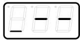
The third digit of the display will blink, and the PCR-30/50/80 will wait to receive bulk data.

About the display in Bulk mode

Transmit bulk data from your sequencer or other device.
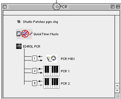
Specify "PCR" (Mac OS 9/8: PCR 1) as the MIDI output device for your sequencer software. For details on this setting, refer to the manual of your sequencer software.
For details on the port that will be used to transfer bulk data, refer to "About the ports when using a USB connection" (p. 79).

When the PCR finishes receiving the bulk data, the display will indicate "END".


Error display
If the data could not be received correctly, the display will blink "ERR".
If this occurs, press the [CANCEL] button to cancel the "ERR" display.
Once "ERR" has been dismissed, perform the bulk reception procedure over again, from step 1.

Confirm what's indicated and press the [ENTER] button.
Transmit mode
1
Press the [EDIT] button.
The display will indicate "EDT".
2
Press the [BULK] key.
3
Press the [1] key.
4
The display will blink "BLT" (Bulk Transmit).
5
Confirm what's indicated and press the [ENTER] button.
The display will indicate "TS", and the "S" will blink.
5
Use the [DEC] [INC] buttons or the [0] [1] keys to select the mode.


| 0 | E5 | SINGLE BULK | The currently recalled memory (the current memory) will be transmitted as bulk data |
| 1 | E4 | ALL BULK | All memories (memories 1–F) will be transmitted as bulk data. |
6
Confirm what's indicated and press the [ENTER] button.
7
The third digit of the display will blink, and the PCR-30/50/80 will wait to transmit bulk data.

8
Press the [ENTER] button.
On your sequencer software, specify "PCR 2" as the MIDI input device. For details on this setting, refer to the manual of your sequencer software.
For details on the port that will be used to transfer bulk data, refer to "About the ports when using a USB connection" (p. 79).
9
When the PCR finishes receiving the bulk data, the display will indicate "END".

1
Confirm what's indicated and press the [ENTER] button.
Here's how you can make various system settings for the PCR-30/50/80.
1
Press the [EDIT] button.
The display will indicate "EDT".
2
Press the [SYSTEM] key.
The display will indicate "SY0".
3
Use the [0]–[8] keys to specify the System setting that you want to set, and then press the [ENTER] button.
Confirm what's indicated and use the appropriate method to make the setting.


| Key-board | Mode | Content of the setting | Default | Setting method |
| 0 | F8 CLOCK ON/OFF | Specify whether F8 Clock is to be transmitted. | OFF | A (p. 75) |
| 1 | F8 CLOCK DEFAULT TEMPO | If “F8 CLOCK ON/OFF” is ON, specify the default value of the F8 Clock. After the power is turned on, this tempo will continue to be output until you move a controller to which TEMPO is assigned. | 120 | B (p. 75) |
| 2 | F8 CLOCK PORT SET | If “F8 CLOCK ON/OFF” is ON, specify the port from which the F8 Clock is to be transmitted. | PCR 1 | C (p. 75) |
| 3 | VELOCITY OFFSET | The value you specify here will be added to the velocity of the notes played from the keyboard. * If the result of the addition would exceed 7FH, the velocity will be 7FH. | 0 | B (p. 75) |
| 4 | KEYBOARD PORT SET | Specify the port from which messages produced by the BENDER lever of the keyboard are to be transmitted. | PCR 1 | C (p. 75) |
| 5 | H-ACTIVITY ON/OFF | Turn this ON if you are using certain applications (such as Pro Tools LE). When ON, “90 00 7F” will be output from PCR 2 approximately every 500 ms. | OFF | A (p. 75) |
| 6 | USB DRIVER MODE | Specify the type of driver used for USB connection. | Original Driver | D (p. 76) |
| 7 | STARTUP MEMORY | Specify the memory that will be selected when the power is turned on. | GM2 | E (p. 76) |
| 8 | FACTORY RESET | Restore all settings of the PCR-30/50/80 to their factory-set condition. | - | F (p. 76) |
Setting method A
Perform steps 1-3.

Use the [DEC][INC] buttons or the [0] or [1] keys to switch F8 CLOCK or H-ACTIVITY on/off.
| 0 | OFF |
| 1 | ON |
The display will indicate either "ON" or "OFF".

Press the [ENTER] button.
Setting method B
Perform steps 1-3.

Use the [DEC][INC] buttons or the [0]–[F] keys to specify the F8 CLOCK DEFAULT TEMPO or the VELOCITY OFFSET value.
| Keyboard | Mode | Value range |
| 1 | F8 CLOCK DEFAULT TEMPO | 20-250 |
| 3 | VELOCITY OFFSET | 0-127 |
The display will indicate the value.

Press the [ENTER] button.
Setting method C
Perform steps 1-3.

Use the [DEC][INC] buttons or the [0]–[F] keys to specify F8 CLOCK PORT SET or KEYBOARD PORT SET. (→“Specifying the port” (p. 79))
The specified port will indicate in the display.

Press the [ENTER] button.
Setting method D
Perform steps 1-3.

Use the [DEC][INC] buttons or the [0] or [1] keys to specify the USB DRIVER MODE.
| 0 | Original driver | FPT technology is used to perform high-speed MIDI transfer. Normally, we recommend that you use this mode. |
| 1 | Generic driver | Select this if you are using the standard MIDI driver provided by your operating system. |
- FPT = Fast Processing Technology for MIDI Transmission:
Effective use is made of the USB bandwidth according to the amount of MIDI data to be transmitted, ensuring that MIDI data processing will always occur optimally.

Press the [ENTER] button.
Setting method E
Perform steps 1-3.

Use the [DEC][INC] buttons or the [0] or [1] keys to specify the GM2/LAST ACCESS MEMORY setting.
| 0 | GM2 MEMORY | When the PCR starts up, memory number 0 (GM2) will be loaded into current memory (p. 68) regardless of the state in which the power was turned off. | |
| 1 | LAST ACCESS MEMORY | Upon power-up, the PCR-30/50/80 will recall the memory that was last recalled or saved into current memory (p. 68). |

Press the [ENTER] button.
Setting method F
Perform steps 1-3.

The display will indicate "RST".

Press the [ENTER] button.

The display will blink "YES".

Press the [ENTER] button.


Appendixes
This section contains troubleshooting information and explanations of convenient functions. You may read this material as necessary.
Convenient functions. p. 78
Memory sets. p. 84
Troubleshooting. p. 90
MIDI implementation. p. 94
Main specifications.. p. 99
Convenient functions
Setting the input mode
If you are not in Play mode, you can use one of two ways to input a numerical value into the PCR-30/50/80; Decimal input mode or Hexadecimal input mode.
If you want to input decimal numbers, press the [DECIMAL] button. If you want to input hexadecimal numbers, press the [HEX] button. When you turn on the power, the PCR-30/50/80 will start up in Decimal mode.
Decimal and hexadecimal numbers correspond as follows.
Decimal: 0-127
Hexadecimal: 00-7F
However, for MIDI CH and PROGRAM CHANGE, the values are as follows.
| Decimal | Hexadecimal | |
| MIDI CH | 1-16 | 0-F |
| PROGRAM CHANGE | 1-128 | 00-7F |
- Normally, the display will show three digits when using Decimal input mode. For this reason, there will be no indication of the parameter you are now inputting, and you may lose track of what you are doing. If this occurs, you can temporarily switch back to Hexadecimal mode to check the parameter you are inputting. Then switch back to Decimal mode and continue.
Specifying the button mode
When you make Assign settings (p. 46) in Edit mode to assign a message to a button, you must specify the operating mode of the button (button mode).
- Press the [0] or [1] key to select either Latch mode or Toggle mode.
| 0 | Latch mode | The setting will turn on when you press the button, and off when you release it. The button will remain lit while you are pressing it. | |
| 1 | Toggle mode | The setting will alternate on/off each time you press the button. The button will light when an On message is transmitted, and will go dark when an Off message is transmitted. |
-
Press the [ENTER] button.
-
When you use a button as a controller, turning the button on will transmit the maximum specified value, and turning it off will transmit the minimum value.
Specifying the port
When you are making Assign settings (p. 39) in Edit mode and have selected Advanced mode, you must specify the USB port to which the message assigned to the controller will be sent when using a USB connection.
- Press a key [1]–[3] to select the port.
| 1 | PORT 1 | Messages will be sent to “PCR 1”. | |
| 2 | PORT 2 | Messages will be sent to “PCR 2”. | |
| 3 | PORT 1,2 | Messages will be sent to both “PCR 1” and “PCR 2”. |
-
Press the [ENTER] button.
-
If you are using the PCR-30/50/80 with a MIDI connection, the messages will be transmitted from the MIDI OUT connector regardless of this port setting.
About the ports when using a USB connection
The ports correspond to the PCR-30/50/80 as follows.
| MIDI OUT device | |
| PCR MIDI OUT (Mac OS 9/8: PCR MIDI) | If you specify PCR MIDI OUT as the output port for your sequencer software, the MIDI messages will be sent from the MIDI OUT connector of the PCR-30/50/80. |
| PCR (Mac OS 9/8: PCR 1) | This is the Bulk reception port. When receiving bulk data into the PCR-30/50/80, specify PCR as the output port for your sequencer software. |
| MIDI IN device | |
| PCR MIDI IN (Mac OS 9/8: PCR MIDI) | If you specify PCR MIDI IN as the input port for your sequencer software, MIDI messages from the MIDI IN connector of the PCR-30/50/80 can be received. |
| PCR 1 PCR 2 | This is the port at which messages from the keyboard, BENDER lever, and control-lers will be input. The keyboard, BENDER lever, and controllers will be mapped to PCR 1 and/or PCR 2 according to the port setting. You may find it convenient to specify PCR 1 for messages used to play a software synthesizer or for realtime recording on a sequencer track, and specify PCR 2 for messages used to control the sequencer, such as sequencer play/stop or track fader control. PCR 2 is the bulk transmission port. When transmitting bulk data from the PCR-30/50/80, specify PCR 2 as the input port for your sequencer software. |
Sys Ex. ASSIGN items
■ Specifying the checksum
The PCR-30/50/80 can automatically calculate the checksum of a system exclusive message and embed it in the message. In order to use this function, you must use the following procedure to specify the starting location from which the checksum is calculated, and the location at which the checksum is inserted. You can also select the type of checksum.
For an actual example, please read the Sys Ex. ASSIGN section "Bend Pitch Control" (p. 64)
- Press the [CHECKSUM] key before you input the byte at which checksum calculation should begin.
The display will indicate "CSS" (Checksum Start).
If you press the [CHECKSUM] key once again, "CSS" (Checksum Start) will be cancelled.

- Press the [ENTER] button.
- Continue inputting data.
- Press the [CHECKSUM] key at the location where the checksum should be inserted.
The display will indicate "CS1" (Checksum type 1).
- Press the [ENTER] button.

Checksum types
There are two types of checksum, as follows.
| 1 | CHECKSUM TYPE 1 | This is the method used by Roland and most other manufacturers |
| 2 | CHECKSUM TYPE 2 | Select this if the method other than type 1 is used |
Switching the type
If you want to switch to type 2, press the [2] key after you press [CHECKSUM] in step 4. To switch back to type 1, press the [1] key.
■ Specifying the location of the data
Here's how to specify the location and data type of the variable portion (data) within a system exclusive message.
The range of data values will be the default range in the case of Basic mode or Advanced mode 3.
In the case of Advanced modes 1 and 4, you can specify the range of data values.
For an actual example, please read the Sys Ex, ASSIGN section "Master Volume" (p. 63).
- Press the [DATA] key at the location where you want to input the data.
The display will indicate "DT0".
- Use the [0]-[4] keys to select the type of data.
| Data number | Data type | Default range | Target of range setting | Example (specified upper/ lower limits) |
| DT0 | 7bit | 00H-7F | Specify the range of data (00-7FH) | 04-45 (lower limit 4H, upper limit 45H) |
| DT1 | 4bit/4bit | 0H/0H-FH/FH | Specify the range of the first byte (0-FH), second byte is fixed at 0-FH | 0/0-D/F (lower limit 0H, upper limit DH) |
| DT2 | 7bit/7bit (MSB/LSB) | 00H/00H-7FH/7FH | Specify the MSB range (00-7F), LSB is fixed at 00-7F | 23/00-68/7F (lower limit 23H, upper limit 68H) |
| DT3 | 7bit/7bit (LSB/MSB) | 00H/00H-7FH/7FH | Specify the MSB range (00-7F), LSB is fixed at 00-7F | 00/23-7F/68 (lower limit 23H, upper limit 68H) |
| DT4 | 4bit/4bit/ 4bit/4bit | 7H/FH/0H/1H-8H/0H/FH/FH | Specify the limits of positive/negative change as a value from 00H to FFH, centered on 8000H. min 8000H max FFF | 7/F/0/2-8/0/5/0 (lower limit FEH, upper limit 50H) |
-
In the case of DT1--DT4 (data consisting of two or more bytes), a data location will automatically be allocated for the next byte, and "-DT" will be displayed. (This cannot be changed.)
-
Press the [ENTER] button.
- If you selected DT1 through DT4, the display will indicate "-DT".
Press the [ENTER] button.
■ Inputting channel/block data
If a system exclusive message includes a channel or GS block number, here's how to specify the type and the value of the upper bits. For the channel and block number, the setting of the current channel (p. 38) will be inserted as the lower bits. (The block number is not actually a channel, but corresponds to the "part" within a GS sound module. On the PCR-30/50/80, this corresponds to the channel for the sake of convenience.)
| Current channel | 1 | 2 | 3 | 4 | 5 | 6 | 7 | 8 | 9 | 10 | 11 | 12 | 13 | 14 | 15 | 16 |
| CH | 0 | 1 | 2 | 3 | 4 | 5 | 6 | 7 | 8 | 9 | A | B | C | D | E | F |
| BL | 1 | 2 | 3 | 4 | 5 | 6 | 7 | 8 | 9 | 0 | A | B | C | D | E | F |
For an actual example, refer to "Bend Pitch Control" (p. 64) in the section on the Edit Mode.
- Press the [DATA] key several times at the location where you want to input the channel/block number, to select "0CH" for the channel or "0BL" for the block.
- Use the [0]-[7] keys to input the value of the upper four bits.
The "0" in the display will change to the numerical value that you input.
- Press the [ENTER] button.
When you press the [V-LINK] button, the PCR will transmit a V-LINK ON message and will enter V-LINK mode. When you press the [V-LINK] button once again, the PCR will transmit a V-LINK OFF message and will exit V-LINK mode.
When the PCR enters V-LINK mode, it will transmit the following parameters to the V-LINK host.
- Clip Ctrl Rx MIDI ch : 16
Color Ctrl Rx MIDI ch : 16 - Sender Model Name : EDIROL PCR
In V-LINK mode, the PCR will operate as follows.
- Messages from the PCR itself will be transmitted to both the MIDI connector and the USB connector.
- In V-LINK mode, you cannot use the MIDI connectors as a USB MIDI interface.
- When you play the keyboard, program change messages or bank select MSB messages will be transmitted in addition to note messages.
- The program change messages and bank select MSB messages will be transmitted on channel 16.
| Note | Number | Pro-gram Change | Bank Select MSB |
| C2 | 36 | 1 | |
| C#2 | 37 | 0 | |
| D2 | 38 | 2 | |
| D#2 | 39 | 1 | |
| E2 | 40 | 3 | |
| F2 | 41 | 4 | |
| F#2 | 42 | 2 | |
| G2 | 43 | 5 | |
| G#2 | 44 | 3 | |
| A2 | 45 | 6 | |
| A#2 | 46 | 4 | |
| B2 | 47 | 7 | |
| C3 | 48 | 8 | |
| C#3 | 49 | 5 | |
| D3 | 50 | 9 | |
| D#3 | 51 | 6 | |
| E3 | 52 | 10 | |
| F3 | 53 | 11 | |
| F#3 | 54 | 7 | |
| G3 | 55 | 12 | |
| G#3 | 56 | 8 | |
| A3 | 57 | 13 | |
| A#3 | 58 | 9 | |
| B3 | 59 | 14 | |
| C4 | 60 | 15 | |
| C#4 | 61 | 10 | |
| D4 | 62 | 16 | |
| D#4 | 63 | 11 | |
| E4 | 64 | 17 | |
| F4 | 65 | 18 | |
| F#4 | 66 | 12 | |
| G4 | 67 | 19 | |
| G#4 | 68 | 13 | |
| A4 | 69 | 20 | |
| A#4 | 70 | 14 | |
| B4 | 71 | 21 | |
| C5 | 72 | 22 | |
| C#5 | 73 | 15 | |
| D5 | 74 | 23 | |
| D#5 | 75 | 16 | |
| E5 | 76 | 24 | |
| F5 | 77 | 25 | |
| F#5 | 78 | 17 | |
| G5 | 79 | 26 | |
| G#5 | 80 | 18 | |
| A5 | 81 | 27 | |
| A#5 | 82 | 19 | |
| B5 | 83 | 28 | |
| C6 | 84 | 29 | |
| C#6 | 85 | ||
| D6 | 86 | 30 | |
| D#6 | 87 | ||
| E6 | 88 | 31 | |
| F6 | 89 | 21 |
Memory sets
With the factory settings, the GM2 set shown in the illustration is assigned to the controllers.
Use the included template.
The following memory sets are also provided.
GM2 set (MEMORY: 0) (p. 84)
MCR-8 MODE 3(SONAR 2) SET. (p. 85)
MCR-8 MODE 3(SONAR 2) - A (MEMORY: 1)....(p. 85)
MCR-8 MODE 3(SONAR 2) - B (MEMORY: 2) .........(p. 85)
MCR-8 MODE 3(SONAR 2) - C (MEMORY: 3)............(p. 85)
MCR-8 MODE 3(SONAR 2) - D (MEMORY: 4).... (p. 85)
MCR-8 MODE 4(Cubase 5/SX) SET. (p. 86)
MCR-8 MODE 4(Cubase 5/SX)-A (MEMORY: 5)....(p. 86)
MCR-8 MODE 4(Cubase 5/SX)-B (MEMORY: 6) ....(p. 86)
MCR-8 MODE 4(Cubase 5/SX) - C (MEMORY: 7)....(p. 86)
MCR-8 MODE 4(Cubase 5/SX)-D (MEMORY: 8)...(p. 86)
H-COMPATIBLE (ProTools LE, Digital Performer) SET
(MEMORY: 9) (p. 87)
GS SET (p. 87)
GS-A (MEMORY: A) (p. 87)
GS-B (MEMORY: B) (p. 88)
GS-C (MEMORY: C) (p. 88)
XG SET. (p. 89)
XG-A (MEMORY: D). (p. 89)
XG-B (MEMORY: E) (p. 89)
For details on settings for actually using each memory set with your application, refer to the Read Me file for each memory set, located in the Memory Files folder of the CD-ROM.
You can download the latest additional memory sets from the following website.
GM2 set (MEMORY: 0)
| Parameter | Message (Hex.) | Range (Hex.) | Ch. | Port | |
| R1 | FILTER CUTOFF | CC 74(4A) | 0(00) - 127(7F) | 1 | 1 |
| R2 | FILTER RESONANCE | CC 71(47) | 0(00) - 127(7F) | 1 | 1 |
| R3 | VIBRATO RATE | CC 76(4C) | 0(00) - 127(7F) | 1 | 1 |
| R4 | VIBRATO DEPTH | CC 77(4D) | 0(00) - 127(7F) | 1 | 1 |
| R5 | VIBRATO DELAY | CC 78(4E) | 0(00) - 127(7F) | 1 | 1 |
| R6 | COARSE TUNING | RPN 0/2(00/02) | 0/-(00/-) - 127/-(7F/-) | 1 | 1 |
| R7 | FINE TUNING | RPN 0/1(00/01) | 0/0(00/00) - 127/127(7F/7F) | 1 | 1 |
| R8 | PAN (CHANNEL) | CC 10(0A) | 0(00) - 127(7F) | 1 | 1 |
| S1 | PORTAMENTO TIME | CC 5(05) | 0(00) - 127(7F) | 1 | 1 |
| S2 | AFTERTOUCH | CHANNEL PRESSURE | 0(00) - 127(7F) | 1 | 1 |
| S3 | ENVELOPE ATTACK | CC 73(49) | 0(00) - 127(7F) | 1 | 1 |
| S4 | ENVELOPE DECAY | CC 75(4B) | 0(00) - 127(7F) | 1 | 1 |
| S5 | ENVELOPE RELEASE | CC 72(48) | 0(00) - 127(7F) | 1 | 1 |
| S6 | CHORUS | CC 93(5D) | 0(00) - 127(7F) | 1 | 1 |
| S7 | REVERB | CC 91(5B) | 0(00) - 127(7F) | 1 | 1 |
| S8 | VOLUME (CHANNEL) | CC 7(07) | 0(00) - 127(7F) | 1 | 1 |
| B1 | PROGRAM CHANGE DEC | PROGRAM CHANGE | min:1(00) | - | - |
| B2 | PROGRAM CHANGE INC | PROGRAM CHANGE | max:128(7F) | - | - |
| B3 | PORTAMENTO ON/OFF | CC 65(41) | 0(00) / 127(7F) | 1 | 1 |
| B4 | POLY MODE ON | B0 7F 00 | - | 1 | 1 |
| B5 | MONO MODE ON | B0 7E 01 | - | 1 | 1 |
| B6 | GM2 SYSTEM ON | F0 7E 7F 09 03 F7 | - | - | 1 |
| L1 | STOP | FC | - | - | 2 |
| L2 | START | FA | - | - | 2 |
| L3 | CONTINUE | FB | - | - | 2 |
| P1 | HOLD | CC 64(40) | 0(00) / 127(7F) | 1 | 1 |
| P2 | EXPRESSION | CC 11(0B) | 0(00) - 127(7F) | 1 | 1 |
MCR-8 MODE 3(SONAR 2) SET
When using this memory set, turn the PCR-30/50/80's OMNI (p. 69) setting OFF.
- To display the external controller toolbar, open Display | Toolbars, and select External Controllers.
MCR-8 MODE 3(SONAR 2) - A (MEMORY: 1)
| Parameter | Message (Hex.) | Range (Hex.) | Ch. | Port | ||
| R1 | TRACK 1 | *1 | CC 16(10) | 0(00) - 127(7F) | 1 | 2 |
| R2 | TRACK 2 | *1 | CC 16(10) | 0(00) - 127(7F) | 2 | 2 |
| R3 | TRACK 3 | *1 | CC 16(10) | 0(00) - 127(7F) | 3 | 2 |
| R4 | TRACK 4 | *1 | CC 16(10) | 0(00) - 127(7F) | 4 | 2 |
| R5 | TRACK 5 | *1 | CC 16(10) | 0(00) - 127(7F) | 5 | 2 |
| R6 | TRACK 6 | *1 | CC 16(10) | 0(00) - 127(7F) | 6 | 2 |
| R7 | TRACK 7 | *1 | CC 16(10) | 0(00) - 127(7F) | 7 | 2 |
| R8 | TRACK 8 | *1 | CC 16(10) | 0(00) - 127(7F) | 8 | 2 |
| S1 | TRACK 1 | *2 | CC 17(11) | 0(00) - 127(7F) | 1 | 2 |
| S2 | TRACK 2 | *2 | CC 17(11) | 0(00) - 127(7F) | 2 | 2 |
| S3 | TRACK 3 | *2 | CC 17(11) | 0(00) - 127(7F) | 3 | 2 |
| S4 | TRACK 4 | *2 | CC 17(11) | 0(00) - 127(7F) | 4 | 2 |
| S5 | TRACK 5 | *2 | CC 17(11) | 0(00) - 127(7F) | 5 | 2 |
| S6 | TRACK 6 | *2 | CC 17(11) | 0(00) - 127(7F) | 6 | 2 |
| S7 | TRACK 7 | *2 | CC 17(11) | 0(00) - 127(7F) | 7 | 2 |
| S8 | TRACK 8 | *2 | CC 17(11) | 0(00) - 127(7F) | 8 | 2 |
| B1 | TRACK 1 | *3 | CC 80(50) | 0(00) / 127(7F) | 1 | 2 |
| B2 | TRACK 2 | *3 | CC 80(50) | 0(00) / 127(7F) | 2 | 2 |
| B3 | TRACK 3 | *3 | CC 80(50) | 0(00) / 127(7F) | 3 | 2 |
| B4 | TRACK 4 | *3 | CC 80(50) | 0(00) / 127(7F) | 4 | 2 |
| B5 | TRACK 5 | *3 | CC 80(50) | 0(00) / 127(7F) | 5 | 2 |
| B6 | TRACK 6 | *3 | CC 80(50) | 0(00) / 127(7F) | 6 | 2 |
| L1 | << | CC 82(52) | 0(00) / 127(7F) | 13 | 2 | |
| L2 | ■ Stop | CC 82(52) | 0(00) / 127(7F) | 14 | 2 | |
| L3 | > Play | CC 82(52) | 0(00) / 127(7F) | 15 | 2 | |
| P1 | HOLD | CC 64(40) | 0(00) / 127(7F) | 1 | 1 | |
| P2 | EXPRESSION | CC 11(0B) | 0(00) - 127(7F) | 1 | 1 | |
MCR-8 MODE 3(SONAR 2) - B (MEMORY: 2)
| Parameter | Message (Hex.) | Range (Hex.) | Ch. | Port | ||
| R1 | TRACK 1 | *1 | CC 16(10) | 0(00) - 127(7F) | 1 | 2 |
| R2 | TRACK 2 | *1 | CC 16(10) | 0(00) - 127(7F) | 2 | 2 |
| R3 | TRACK 3 | *1 | CC 16(10) | 0(00) - 127(7F) | 3 | 2 |
| R4 | TRACK 4 | *1 | CC 16(10) | 0(00) - 127(7F) | 4 | 2 |
| R5 | TRACK 5 | *1 | CC 16(10) | 0(00) - 127(7F) | 5 | 2 |
| R6 | TRACK 6 | *1 | CC 16(10) | 0(00) - 127(7F) | 6 | 2 |
| R7 | TRACK 7 | *1 | CC 16(10) | 0(00) - 127(7F) | 7 | 2 |
| R8 | TRACK 8 | *1 | CC 16(10) | 0(00) - 127(7F) | 8 | 2 |
| S1 | TRACK 1 | *2 | CC 17(11) | 0(00) - 127(7F) | 1 | 2 |
| S2 | TRACK 2 | *2 | CC 17(11) | 0(00) - 127(7F) | 2 | 2 |
| S3 | TRACK 3 | *2 | CC 17(11) | 0(00) - 127(7F) | 3 | 2 |
| S4 | TRACK 4 | *2 | CC 17(11) | 0(00) - 127(7F) | 4 | 2 |
| S5 | TRACK 5 | *2 | CC 17(11) | 0(00) - 127(7F) | 5 | 2 |
| S6 | TRACK 6 | *2 | CC 17(11) | 0(00) - 127(7F) | 6 | 2 |
| S7 | TRACK 7 | *2 | CC 17(11) | 0(00) - 127(7F) | 7 | 2 |
| S8 | TRACK 8 | *2 | CC 17(11) | 0(00) - 127(7F) | 8 | 2 |
| B1 | TRACK 1 | *4 | CC 81(51) | 0(00) / 127(7F) | 1 | 2 |
| B2 | TRACK 2 | *4 | CC 81(51) | 0(00) / 127(7F) | 2 | 2 |
| B3 | TRACK 3 | *4 | CC 81(51) | 0(00) / 127(7F) | 3 | 2 |
| B4 | TRACK 4 | *4 | CC 81(51) | 0(00) / 127(7F) | 4 | 2 |
| B5 | TRACK 5 | *4 | CC 81(51) | 0(00) / 127(7F) | 5 | 2 |
| B6 | TRACK 6 | *4 | CC 81(51) | 0(00) / 127(7F) | 6 | 2 |
| L1 | << | CC 82(52) | 0(00) / 127(7F) | 13 | 2 | |
| L2 | ■ Stop | CC 82(52) | 0(00) / 127(7F) | 14 | 2 | |
| L3 | > Play | CC 82(52) | 0(00) / 127(7F) | 15 | 2 | |
| P1 | HOLD | CC 64(40) | 0(00) / 127(7F) | 1 | 1 | |
| P2 | EXPRESSION | CC 11(0B) | 0(00) - 127(7F) | 1 | 1 | |
MCR-8 MODE 3(SONAR 2) - C (MEMORY: 3)
| Parameter | Message (Hex.) | Range (Hex.) | Ch. | Port | ||
| R1 | TRACK 9 | *1 | CC 16(10) | 0(00) - 127(7F) | 9 | 2 |
| R2 | TRACK 10 | *1 | CC 16(10) | 0(00) - 127(7F) | 10 | 2 |
| R3 | TRACK 11 | *1 | CC 16(10) | 0(00) - 127(7F) | 11 | 2 |
| R4 | TRACK 12 | *1 | CC 16(10) | 0(00) - 127(7F) | 12 | 2 |
| R5 | TRACK 13 | *1 | CC 16(10) | 0(00) - 127(7F) | 13 | 2 |
| R6 | TRACK 14 | *1 | CC 16(10) | 0(00) - 127(7F) | 14 | 2 |
| R7 | TRACK 15 | *1 | CC 16(10) | 0(00) - 127(7F) | 15 | 2 |
| R8 | TRACK 16 | *1 | CC 16(10) | 0(00) - 127(7F) | 16 | 2 |
| S1 | TRACK 9 | *2 | CC 17(11) | 0(00) - 127(7F) | 9 | 2 |
| S2 | TRACK 10 | *2 | CC 17(11) | 0(00) - 127(7F) | 10 | 2 |
| S3 | TRACK 11 | *2 | CC 17(11) | 0(00) - 127(7F) | 11 | 2 |
| S4 | TRACK 12 | *2 | CC 17(11) | 0(00) - 127(7F) | 12 | 2 |
| S5 | TRACK 13 | *2 | CC 17(11) | 0(00) - 127(7F) | 13 | 2 |
| S6 | TRACK 14 | *2 | CC 17(11) | 0(00) - 127(7F) | 14 | 2 |
| S7 | TRACK 15 | *2 | CC 17(11) | 0(00) - 127(7F) | 15 | 2 |
| S8 | TRACK 16 | *2 | CC 17(11) | 0(00) - 127(7F) | 16 | 2 |
| B1 | TRACK 9 | *3 | CC 80(50) | 0(00) / 127(7F) | 9 | 2 |
| B2 | TRACK 10 | *3 | CC 80(50) | 0(00) / 127(7F) | 10 | 2 |
| B3 | TRACK 11 | *3 | CC 80(50) | 0(00) / 127(7F) | 11 | 2 |
| B4 | TRACK 12 | *3 | CC 80(50) | 0(00) / 127(7F) | 12 | 2 |
| B5 | TRACK 13 | *3 | CC 80(50) | 0(00) / 127(7F) | 13 | 2 |
| B6 | TRACK 14 | *3 | CC 80(50) | 0(00) / 127(7F) | 14 | 2 |
| L1 | Automation Write | CC 82(52) | 0(00) / 127(7F) | 12 | 2 | |
| L2 | ■ Stop | CC 82(52) | 0(00) / 127(7F) | 14 | 2 | |
| L3 | Rec | CC 82(52) | 0(00) / 127(7F) | 11 | 2 | |
| P1 | HOLD | CC 64(40) | 0(00) / 127(7F) | 1 | 1 | |
| P2 | EXPRESSION | CC 11(0B) | 0(00) - 127(7F) | 1 | 1 | |
MCR-8 MODE 3(SONAR 2) - D (MEMORY: 4)
| Parameter | Message (Hex.) | Range (Hex.) | Ch. | Port | ||
| R1 | TRACK 9 | *1 | CC 16(10) | 0(00) - 127(7F) | 9 | 2 |
| R2 | TRACK 10 | *1 | CC 16(10) | 0(00) - 127(7F) | 10 | 2 |
| R3 | TRACK 11 | *1 | CC 16(10) | 0(00) - 127(7F) | 11 | 2 |
| R4 | TRACK 12 | *1 | CC 16(10) | 0(00) - 127(7F) | 12 | 2 |
| R5 | TRACK 13 | *1 | CC 16(10) | 0(00) - 127(7F) | 13 | 2 |
| R6 | TRACK 14 | *1 | CC 16(10) | 0(00) - 127(7F) | 14 | 2 |
| R7 | TRACK 15 | *1 | CC 16(10) | 0(00) - 127(7F) | 15 | 2 |
| R8 | TRACK 16 | *1 | CC 16(10) | 0(00) - 127(7F) | 16 | 2 |
| S1 | TRACK 9 | *2 | CC 17(11) | 0(00) - 127(7F) | 9 | 2 |
| S2 | TRACK 10 | *2 | CC 17(11) | 0(00) - 127(7F) | 10 | 2 |
| S3 | TRACK 11 | *2 | CC 17(11) | 0(00) - 127(7F) | 11 | 2 |
| S4 | TRACK 12 | *2 | CC 17(11) | 0(00) - 127(7F) | 12 | 2 |
| S5 | TRACK 13 | *2 | CC 17(11) | 0(00) - 127(7F) | 13 | 2 |
| S6 | TRACK 14 | *2 | CC 17(11) | 0(00) - 127(7F) | 14 | 2 |
| S7 | TRACK 15 | *2 | CC 17(11) | 0(00) - 127(7F) | 15 | 2 |
| S8 | TRACK 16 | *2 | CC 17(11) | 0(00) - 127(7F) | 16 | 2 |
| B1 | TRACK 9 | *4 | CC 81(51) | 0(00) / 127(7F) | 9 | 2 |
| B2 | TRACK 10 | *4 | CC 81(51) | 0(00) / 127(7F) | 10 | 2 |
| B3 | TRACK 11 | *4 | CC 81(51) | 0(00) / 127(7F) | 11 | 2 |
| B4 | TRACK 12 | *4 | CC 81(51) | 0(00) / 127(7F) | 12 | 2 |
| B5 | TRACK 13 | *4 | CC 81(51) | 0(00) / 127(7F) | 13 | 2 |
| B6 | TRACK 14 | *4 | CC 81(51) | 0(00) / 127(7F) | 14 | 2 |
| L1 | Automation Write | CC 82(52) | 0(00) / 127(7F) | 12 | 2 | |
| L2 | ■ Stop | CC 82(52) | 0(00) / 127(7F) | 14 | 2 | |
| L3 | Rec | CC 82(52) | 0(00) / 127(7F) | 11 | 2 | |
| P1 | HOLD | CC 64(40) | 0(00) / 127(7F) | 1 | 1 | |
| P2 | EXPRESSION | CC 11(0B) | 0(00) - 127(7F) | 1 | 1 | |
| Generic Surface Preset | *1 | *2 | *3 | *4 |
| Roland MCR-8 (Aus Send 1) | Aux Send 1 Pan | Aux Send 1 Level | Aux Send 1 Pre/Post | Aux Send 1 Enable |
| Roland MCR-8 (Aus Send 2) | Aux Send 2 Pan | Aux Send 2 Level | Aux Send 2 Pre/Post | Aux Send 2 Enable |
| Roland MCR-8 (Mute + Solo) | Pan | Volume | Mute | Solo |
| Roland MCR-8 (Record Arming) | Pan | Volume | White Arm | Record Arm |
MCR-8 MODE 4(Cubase 5/SX) SET
When using this memory set, turn the PCR-30/50/80's OMNI (p. 69) setting OFF.
MCR-8 MODE 4(Cubase 5/SX) - A (MEMORY: 5)
| Parameter | Message (Hex.) | Range (Hex.) | Ch. | Port | |
| R1 | TRACK 1 PAN | CC 72(48) | 0(00) - 127(7F) | 16 | 2 |
| R2 | TRACK 2 PAN | CC 73(49) | 0(00) - 127(7F) | 16 | 2 |
| R3 | TRACK 3 PAN | CC 74(4A) | 0(00) - 127(7F) | 16 | 2 |
| R4 | TRACK 4 PAN | CC 75(4B) | 0(00) - 127(7F) | 16 | 2 |
| R5 | TRACK 5 PAN | CC 76(4C) | 0(00) - 127(7F) | 16 | 2 |
| R6 | TRACK 6 PAN | CC 77(4D) | 0(00) - 127(7F) | 16 | 2 |
| R7 | TRACK 7 PAN | CC 78(4E) | 0(00) - 127(7F) | 16 | 2 |
| R8 | TRACK 8 PAN | CC 79(4F) | 0(00) - 127(7F) | 16 | 2 |
| S1 | TRACK 1 FADER | CC 64(40) | 0(00) - 127(7F) | 16 | 2 |
| S2 | TRACK 2 FADER | CC 65(41) | 0(00) - 127(7F) | 16 | 2 |
| S3 | TRACK 3 FADER | CC 66(42) | 0(00) - 127(7F) | 16 | 2 |
| S4 | TRACK 4 FADER | CC 67(43) | 0(00) - 127(7F) | 16 | 2 |
| S5 | TRACK 5 FADER | CC 68(44) | 0(00) - 127(7F) | 16 | 2 |
| S6 | TRACK 6 FADER | CC 69(45) | 0(00) - 127(7F) | 16 | 2 |
| S7 | TRACK 7 FADER | CC 70(46) | 0(00) - 127(7F) | 16 | 2 |
| S8 | TRACK 8 FADER | CC 71(47) | 0(00) - 127(7F) | 16 | 2 |
| B1 | TRACK 1 SOLO | CC 0(00) | 0(00) / 127(7F) | 16 | 2 |
| B2 | TRACK 2 SOLO | CC 1(01) | 0(00) / 127(7F) | 16 | 2 |
| B3 | TRACK 3 SOLO | CC 2(02) | 0(00) / 127(7F) | 16 | 2 |
| B4 | TRACK 4 SOLO | CC 3(03) | 0(00) / 127(7F) | 16 | 2 |
| B5 | TRACK 5 SOLO | CC 4(04) | 0(00) / 127(7F) | 16 | 2 |
| B6 | TRACK 6 SOLO | CC 5(05) | 0(00) / 127(7F) | 16 | 2 |
| L1 | << | CC 19(13) | 0(00) / 127(7F) | 16 | 2 |
| L2 | ■ Stop | CC 21(15) | 0(00) / 127(7F) | 16 | 2 |
| L3 | > Play | CC 22(16) | 0(00) / 127(7F) | 16 | 2 |
| P1 | HOLD | CC 64(40) | 0(00) / 127(7F) | 1 | 1 |
| P2 | EXPRESSION | CC 11(0B) | 0(00) - 127(7F) | 1 | 1 |
MCR-8 MODE 4(Cubase 5/SX) - C (MEMORY: 7)
| Parameter | Message (Hex.) | Range (Hex.) | Ch. | Port | |
| R1 | TRACK 9 PAN | CC 56(38) | 0(00) - 127(7F) | 16 | 2 |
| R2 | TRACK 10 PAN | CC 57(39) | 0(00) - 127(7F) | 16 | 2 |
| R3 | TRACK 11 PAN | CC 58(3A) | 0(00) - 127(7F) | 16 | 2 |
| R4 | TRACK 12 PAN | CC 59(3B) | 0(00) - 127(7F) | 16 | 2 |
| R5 | TRACK 13 PAN | CC 60(3C) | 0(00) - 127(7F) | 16 | 2 |
| R6 | TRACK 14 PAN | CC 61(3D) | 0(00) - 127(7F) | 16 | 2 |
| R7 | TRACK 15 PAN | CC 62(3E) | 0(00) - 127(7F) | 16 | 2 |
| R8 | TRACK 16 PAN | CC 63(3F) | 0(00) - 127(7F) | 16 | 2 |
| S1 | TRACK 9 FADER | CC 48(30) | 0(00) - 127(7F) | 16 | 2 |
| S2 | TRACK 10 FADER | CC 49(31) | 0(00) - 127(7F) | 16 | 2 |
| S3 | TRACK 11 FADER | CC 50(32) | 0(00) - 127(7F) | 16 | 2 |
| S4 | TRACK 12 FADER | CC 51(33) | 0(00) - 127(7F) | 16 | 2 |
| S5 | TRACK 13 FADER | CC 52(34) | 0(00) - 127(7F) | 16 | 2 |
| S6 | TRACK 14 FADER | CC 53(35) | 0(00) - 127(7F) | 16 | 2 |
| S7 | TRACK 15 FADER | CC 54(36) | 0(00) - 127(7F) | 16 | 2 |
| S8 | TRACK 16 FADER | CC 55(37) | 0(00) - 127(7F) | 16 | 2 |
| B1 | TRACK 9 SOLO | CC 32(20) | 0(00) / 127(7F) | 16 | 2 |
| B2 | TRACK 10 SOLO | CC 33(21) | 0(00) / 127(7F) | 16 | 2 |
| B3 | TRACK 11 SOLO | CC 34(22) | 0(00) / 127(7F) | 16 | 2 |
| B4 | TRACK 12 SOLO | CC 35(23) | 0(00) / 127(7F) | 16 | 2 |
| B5 | TRACK 13 SOLO | CC 36(24) | 0(00) / 127(7F) | 16 | 2 |
| B6 | TRACK 14 SOLO | CC 37(25) | 0(00) / 127(7F) | 16 | 2 |
| L1 | << | CC 20(14) | 0(00) / 127(7F) | 16 | 2 |
| L2 | ■Stop | CC 21(15) | 0(00) / 127(7F) | 16 | 2 |
| L3 | Rec | CC 23(17) | 0(00) / 127(7F) | 16 | 2 |
| P1 | HOLD | CC 64(40) | 0(00) / 127(7F) | 1 | 1 |
| P2 | EXPRESSION | CC 11(OB) | 0(00) - 127(7F) | 1 | 1 |
MCR-8 MODE 4(Cubase 5/SX) - B (MEMORY: 6)
| Parameter | Message (Hex.) | Range (Hex.) | Ch. | Port | |
| R1 | TRACK 1 PAN | CC 72(48) | 0(00) - 127(7F) | 16 | 2 |
| R2 | TRACK 2 PAN | CC 73(49) | 0(00) - 127(7F) | 16 | 2 |
| R3 | TRACK 3 PAN | CC 74(4A) | 0(00) - 127(7F) | 16 | 2 |
| R4 | TRACK 4 PAN | CC 75(4B) | 0(00) - 127(7F) | 16 | 2 |
| R5 | TRACK 5 PAN | CC 76(4C) | 0(00) - 127(7F) | 16 | 2 |
| R6 | TRACK 6 PAN | CC 77(4D) | 0(00) - 127(7F) | 16 | 2 |
| R7 | TRACK 7 PAN | CC 78(4E) | 0(00) - 127(7F) | 16 | 2 |
| R8 | TRACK 8 PAN | CC 79(4F) | 0(00) - 127(7F) | 16 | 2 |
| S1 | TRACK 1 FADER | CC 64(40) | 0(00) - 127(7F) | 16 | 2 |
| S2 | TRACK 2 FADER | CC 65(41) | 0(00) - 127(7F) | 16 | 2 |
| S3 | TRACK 3 FADER | CC 66(42) | 0(00) - 127(7F) | 16 | 2 |
| S4 | TRACK 4 FADER | CC 67(43) | 0(00) - 127(7F) | 16 | 2 |
| S5 | TRACK 5 FADER | CC 68(44) | 0(00) - 127(7F) | 16 | 2 |
| S6 | TRACK 6 FADER | CC 69(45) | 0(00) - 127(7F) | 16 | 2 |
| S7 | TRACK 7 FADER | CC 70(46) | 0(00) - 127(7F) | 16 | 2 |
| S8 | TRACK 8 FADER | CC 71(47) | 0(00) - 127(7F) | 16 | 2 |
| B1 | TRACK 1 MUTE | CC 40(28) | 0(00) / 127(7F) | 16 | 2 |
| B2 | TRACK 2 MUTE | CC 41(29) | 0(00) / 127(7F) | 16 | 2 |
| B3 | TRACK 3 MUTE | CC 42(2A) | 0(00) / 127(7F) | 16 | 2 |
| B4 | TRACK 4 MUTE | CC 43(2B) | 0(00) / 127(7F) | 16 | 2 |
| B5 | TRACK 5 MUTE | CC 44(2C) | 0(00) / 127(7F) | 16 | 2 |
| B6 | TRACK 6 MUTE | CC 45(2D) | 0(00) / 127(7F) | 16 | 2 |
| L1 | << | CC 19(13) | 0(00) / 127(7F) | 16 | 2 |
| L2 | ■ Stop | CC 21(15) | 0(00) / 127(7F) | 16 | 2 |
| L3 | > Play | CC 22(16) | 0(00) / 127(7F) | 16 | 2 |
| P1 | HOLD | CC 64(40) | 0(00) / 127(7F) | 1 | 1 |
| P2 | EXPRESSION | CC 11(OB) | 0(00) - 127(7F) | 1 | 1 |
MCR-8 MODE 4(Cubase 5/SX) - D (MEMORY: 8)
| Parameter | Message (Hex.) | Range (Hex.) | Ch. | Port | |
| R1 | TRACK 9 PAN | CC 56(38) | 0(00) - 127(7F) | 16 | 2 |
| R2 | TRACK 10 PAN | CC 57(39) | 0(00) - 127(7F) | 16 | 2 |
| R3 | TRACK 11 PAN | CC 58(3A) | 0(00) - 127(7F) | 16 | 2 |
| R4 | TRACK 12 PAN | CC 59(3B) | 0(00) - 127(7F) | 16 | 2 |
| R5 | TRACK 13 PAN | CC 60(3C) | 0(00) - 127(7F) | 16 | 2 |
| R6 | TRACK 14 PAN | CC 61(3D) | 0(00) - 127(7F) | 16 | 2 |
| R7 | TRACK 15 PAN | CC 62(3E) | 0(00) - 127(7F) | 16 | 2 |
| R8 | TRACK 16 PAN | CC 63(3F) | 0(00) - 127(7F) | 16 | 2 |
| S1 | TRACK 9 FADER | CC 48(30) | 0(00) - 127(7F) | 16 | 2 |
| S2 | TRACK 10 FADER | CC 49(31) | 0(00) - 127(7F) | 16 | 2 |
| S3 | TRACK 11 FADER | CC 50(32) | 0(00) - 127(7F) | 16 | 2 |
| S4 | TRACK 12 FADER | CC 51(33) | 0(00) - 127(7F) | 16 | 2 |
| S5 | TRACK 13 FADER | CC 52(34) | 0(00) - 127(7F) | 16 | 2 |
| S6 | TRACK 14 FADER | CC 53(35) | 0(00) - 127(7F) | 16 | 2 |
| S7 | TRACK 15 FADER | CC 54(36) | 0(00) - 127(7F) | 16 | 2 |
| S8 | TRACK 16 FADER | CC 55(37) | 0(00) - 127(7F) | 16 | 2 |
| B1 | TRACK 9 MUTE | CC 88(58) | 0(00) / 127(7F) | 16 | 2 |
| B2 | TRACK 10 MUTE | CC 89(59) | 0(00) / 127(7F) | 16 | 2 |
| B3 | TRACK 11 MUTE | CC 90(5A) | 0(00) / 127(7F) | 16 | 2 |
| B4 | TRACK 12 MUTE | CC 91(5B) | 0(00) / 127(7F) | 16 | 2 |
| B5 | TRACK 13 MUTE | CC 92(5C) | 0(00) / 127(7F) | 16 | 2 |
| B6 | TRACK 14 MUTE | CC 93(5D) | 0(00) / 127(7F) | 16 | 2 |
| L1 | << | CC 20(14) | 0(00) / 127(7F) | 16 | 2 |
| L2 | ■Stop | CC 21(15) | 0(00) / 127(7F) | 16 | 2 |
| L3 | Rec | CC 23(17) | 0(00) / 127(7F) | 16 | 2 |
| P1 | HOLD | CC 64(40) | 0(00) / 127(7F) | 1 | 1 |
| P2 | EXPRESSION | CC 11(OB) | 0(00) - 127(7F) | 1 | 1 |
H-COMPATIBLE (ProTools LE, Digital Performer) SET (MEMORY: 9)
When using this memory set, turn the PCR-30/50/80's OMNI (p. 69) setting OFF, and turn the H-ACTIVITY (p. 74) setting ON.
| Parameter | Message (Hex.) | Range (Hex.) | Ch. | Port | |
| R1 | ROTARY ENCODER 1 | B0 40 dd | DEC(01) / INC(41) | - | 2 |
| R2 | ROTARY ENCODER 2 | B0 41 dd | DEC(01) / INC(41) | - | 2 |
| R3 | ROTARY ENCODER 3 | B0 42 dd | DEC(01) / INC(41) | - | 2 |
| R4 | ROTARY ENCODER 4 | B0 43 dd | DEC(01) / INC(41) | - | 2 |
| R5 | ROTARY ENCODER 5 | B0 44 dd | DEC(01) / INC(41) | - | 2 |
| R6 | ROTARY ENCODER 6 | B0 45 dd | DEC(01) / INC(41) | - | 2 |
| R7 | ROTARY ENCODER 7 | B0 46 dd | DEC(01) / INC(41) | - | 2 |
| R8 | ROTARY ENCODER 8 | B0 47 dd | DEC(01) / INC(41) | - | 2 |
| S1 | FADER 1 | B0 0F 00 B0 2F 40 B0 00 dd B0 20 00 B0 0F 00 B0 2F 00 | 0(00) - 127(7F) | - | 2 |
| S2 | FADER 2 | B0 0F 01 B0 2F 40 B0 01 dd B0 21 00 B0 0F 01 B0 2F 00 | 0(00) - 127(7F) | - | 2 |
| S3 | FADER 3 | B0 0F 02 B0 2F 40 B0 02 dd B0 22 00 B0 0F 02 B0 2F 00 | 0(00) - 127(7F) | - | 2 |
| S4 | FADER 4 | B0 0F 03 B0 2F 40 B0 03 dd B0 23 00 B0 0F 03 B0 2F 00 | 0(00) - 127(7F) | - | 2 |
| S5 | FADER 5 | B0 0F 04 B0 2F 40 B0 04 dd B0 24 00 B0 0F 04 B0 2F 00 | 0(00) - 127(7F) | - | 2 |
| S6 | FADER 6 | B0 0F 05 B0 2F 40 B0 05 dd B0 25 00 B0 0F 05 B0 2F 00 | 0(00) - 127(7F) | - | 2 |
| S7 | FADER 7 | B0 0F 06 B0 2F 40 B0 06 dd B0 26 00 B0 0F 06 B0 2F 00 | 0(00) - 127(7F) | - | 2 |
| S8 | FADER 8 | B0 0F 07 B0 2F 40 B0 07 dd B0 27 00 B0 0F 07 B0 2F 00 | 0(00) - 127(7F) | - | 2 |
| B1 | MUTE 1 | B0 0F 00 B0 2F dd | ON(42) / OFF(02) | - | 2 |
| B2 | SOLO 1 | B0 0F 00 B0 2F dd | ON(43) / OFF(03) | - | 2 |
| B3 | REC 1 | B0 0F 00 B0 2F dd | ON(47) / OFF(07) | - | 2 |
| B4 | WRITE 1 | B0 0F 00 B0 2F dd | ON(44) / OFF(04) | - | 2 |
| B5 | TRACK < | B0 0F 0A B0 2F dd | ON(40) / OFF(00) | - | 2 |
| B6 | TRACK > | B0 0F 0A B0 2F dd | ON(42) / OFF(02) | - | 2 |
| L1 | REWIND | B0 0F 0E B0 2F dd | ON(41) / OFF(01) | - | 2 |
| L2 | STOP | B0 0F 0E B0 2F dd | ON(43) / OFF(03) | - | 2 |
| L3 | PLAY | B0 0F 0E B0 2F dd | ON(44) / OFF(04) | - | 2 |
| P1 | HOLD | CC 64(40) | 0(00) / 127(7F) | 1 | 1 |
| P2 | EXPRESSION | CC 11(OB) | 0(00) - 127(7F) | 1 | 1 |
GS SET
When using this memory set, you will find it convenient to turn the PCR-30/50/80's OMNI (p. 69) setting ON.
GS-A (MEMORY: A)
| Parameter | Message (Hex.) | Range (Hex.)) | Ch. | Port | |
| R1 | REVERB MACRO | F0 41 10 42 12 40 01 30 dd SUM F7 | 0(00) - 7(07) | - | 1 |
| R2 | REVERB CHARACTER | F0 41 10 42 12 40 01 31 dd SUM F7 | 0(00) - 7(07) | - | 1 |
| R3 | REVERB PRE-LPF | F0 41 10 42 12 40 01 32 dd SUM F7 | 0(00) - 7(07) | - | 1 |
| R4 | REVERB TIME | F0 41 10 42 12 40 01 34 dd SUM F7 | 0(00) - 127(7F) | - | 1 |
| R5 | REVERB PREDELAY TIME | F0 41 10 42 12 40 01 37 dd SUM F7 | 0(00) - 127(7F) | - | 1 |
| R6 | REVERB DELAY FEEDBACK | F0 41 10 42 12 40 01 35 dd SUM F7 | 0(00) - 127(7F) | - | 1 |
| R7 | REVERB LEVEL | F0 41 10 42 12 40 01 33 dd SUM F7 | 0(00) - 127(7F) | - | 1 |
| R8 | PART PANPOT | F0 41 10 42 12 40 1x 1C dd SUM F7 | 1(01) - 127(7F) | BLOCK | 1 |
| S1 | VIBRATO RATE | F0 41 10 42 12 40 1x 30 dd SUM F7 | 0(00) - 64(40) - 127(7F) | BLOCK | 1 |
| S2 | VIBRATO DEPTH | F0 41 10 42 12 40 1x 31 dd SUM F7 | 0(00) - 64(40) - 127(7F) | BLOCK | 1 |
| S3 | VIBRATO DELAY | F0 41 10 42 12 40 1x 37 dd SUM F7 | 0(00) - 64(40) - 127(7F) | BLOCK | 1 |
| S4 | TVF&TVA ENVattaCK | F0 41 10 42 12 40 1x 34 dd SUM F7 | 0(00) - 64(40) - 127(7F) | BLOCK | 1 |
| S5 | TVF&TVA ENV.DecAY | F0 41 10 42 12 40 1x 35 dd SUM F7 | 0(00) - 64(40) - 127(7F) | BLOCK | 1 |
| S6 | TVF&TVA ENV.RELEASE | F0 41 10 42 12 40 1x 36 dd SUM F7 | 0(00) - 64(40) - 127(7F) | BLOCK | 1 |
| S7 | REVERB SEND LEVEL | F0 41 10 42 12 40 1x 22 dd SUM F7 | 0(00) - 127(7F) | BLOCK | 1 |
| S8 | PART LEVEL | F0 41 10 42 12 40 1x 19 dd SUM F7 | 0(00) - 127(7F) | BLOCK | 1 |
| B1 | PROGRAM CHANGE DEC | PROGRAM CHANGE | min:1 (00) | - | - |
| B2 | PROGRAM CHANGE INC | PROGRAM CHANGE | max:128 (7F) | - | - |
| B3 | NRPN ON/OFF | F0 41 10 42 12 40 1x 0A dd SUM F7 | OFF(00) / ON(01) | BLOCK | 1 |
| B4 | RANDOM PAN | F0 41 10 42 12 40 1x 1C 00 SUM F7 | - | BLOCK | 1 |
| B5 | MODE POLY/MONO | F0 41 10 42 12 40 1x 13 dd SUM F7 | MONO(00) / POLY(01) | BLOCK | 1 |
| B6 | GS RESET | F0 41 10 42 12 40 00 7F 00 41 F7 | - | - | 1 |
| L1 | STOP | FC | - | - | 2 |
| L2 | START | FA | - | - | 2 |
| L3 | CONTINUE | FB | - | - | 2 |
| P1 | HOLD | CC 64(40) | 0(00) / 127(7F) | 1 | 1 |
| P2 | EXPRESSION | CC 11(0B) | 0(00) - 127(7F) | 1 | 1 |
GS-B (MEMORY: B)
GS-C (MEMORY: C)
| Parameter | Message (Hex.) | Range (Hex.) | Ch. | Port | |
| R1 | CHORUS MACRO | F0 41 10 42 12 40 01 38 dd SUM F7 | 0(00) - 7(07) | - | 1 |
| R2 | CHORUS PRE-LPF | F0 41 10 42 12 40 01 39 dd SUM F7 | 0(00) - 7(07) | - | 1 |
| R3 | CHORUS DELAY | F0 41 10 42 12 40 01 3C dd SUM F7 | 0(00) - 127(7F) | - | 1 |
| R4 | CHORUS RATE | F0 41 10 42 12 40 01 3D dd SUM F7 | 0(00) - 127(7F) | - | 1 |
| R5 | CHORUS DEPTH | F0 41 10 42 12 40 01 3E dd SUM F7 | 0(00) - 127(7F) | - | 1 |
| R6 | CHORUS FEEDBACK | F0 41 10 42 12 40 01 3B dd SUM F7 | 0(00) - 127(7F) | - | 1 |
| R7 | CHORUS LEVEL | F0 41 10 42 12 40 01 3A dd SUM F7 | 0(00) - 127(7F) | - | 1 |
| R8 | PART PANPOT | F0 41 10 42 12 40 1x 1C dd SUM F7 | 1(01) - 127(7F) | BLOCK | 1 |
| S1 | CHORUS SEND LEVEL TO REVERB | F0 41 10 42 12 40 01 3F dd SUM F7 | 0(00) - 64(40) - 127(7F) | BLOCK | 1 |
| S2 | CHORUS SEND LEVEL TO DELAY | F0 41 10 42 12 40 01 40 dd SUM F7 | 0(00) - 64(40) - 127(7F) | BLOCK | 1 |
| S3 | TVF CUTOFF FREQ | F0 41 10 42 12 40 1x 32 dd SUM F7 | 0(00) - 64(40) - 127(7F) | BLOCK | 1 |
| S4 | TVF RESONANCE | F0 41 10 42 12 40 1x 33 dd SUM F7 | 0(00) - 64(40) - 127(7F) | BLOCK | 1 |
| S5 | MODULATION DEPTH | F0 41 10 42 12 40 2x 04 dd SUM F7 | 0(00) - 127(7F) | BLOCK | 1 |
| S6 | BEND RANGE | F0 41 10 42 12 40 2x 10 dd SUM F7 | 64(40) - 88(58) | BLOCK | 1 |
| S7 | CHORUS SEND LEVEL | F0 41 10 42 12 40 1x 21 dd SUM F7 | 0(00) - 127(7F) | BLOCK | 1 |
| S8 | PART LEVEL | F0 41 10 42 12 40 1x 19 dd SUM F7 | 0(00) - 127(7F) | BLOCK | 1 |
| B1 | PROGRAM CHANGE DEC | PROGRAM CHANGE | min:1 (00) | - | - |
| B2 | PROGRAM CHANGE INC | PROGRAM CHANGE | max:128 (7F) | - | - |
| B3 | NRPN ON/OFF | F0 41 10 42 12 40 1x 0A dd SUM F7 | OFF(00) / ON(01) | BLOCK | 1 |
| B4 | RANDOM PAN | F0 41 10 42 12 40 1x 1C 00 SUM F7 | - | BLOCK | 1 |
| B5 | MODE POLY/MONO | F0 41 10 42 12 40 1x 13 dd SUM F7 | MONO(00) / POLY(01) | BLOCK | 1 |
| B6 | GS RESET | F0 41 10 42 12 40 00 7F 00 41 F7 | - | - | 1 |
| L1 | STOP | FC | - | - | 2 |
| L2 | START | FA | - | - | 2 |
| L3 | CONTINUE | FB | - | - | 2 |
| P1 | HOLD | CC 64(40) | 0(00) / 127(7F) | 1 | 1 |
| P2 | EXPRESSION | CC 11(0B) | 0(00) - 127(7F) | 1 | 1 |
| Parameter | Message (Hex.) | Range (Hex.) | Ch. | Port | |
| R1 | DELAY MACRO | F0 41 10 42 12 40 01 50 dd SUM F7 | 0(00) - 9(09) | - | 1 |
| R2 | DELAY PRE-LPF | F0 41 10 42 12 40 01 51 dd SUM F7 | 0(00) - 7(07) | - | 1 |
| R3 | DELAY TIME RATIO LEFT | F0 41 10 42 12 40 01 53 dd SUM F7 | 1(01) - 120(78) | - | 1 |
| R4 | DELAY TIME CENTER | F0 41 10 42 12 40 01 52 dd SUM F7 | 1(01) - 115(73) | - | 1 |
| R5 | DELAY TIME RATIO RIGHT | F0 41 10 42 12 40 01 54 dd SUM F7 | 1(01) - 120(78) | - | 1 |
| R6 | DELAY FEEDBACK | F0 41 10 42 12 40 01 59 dd SUM F7 | 0(00) - 64(40) - 127(7F) | - | 1 |
| R7 | DELAY LEVEL | F0 41 10 42 12 40 01 58 dd SUM F7 | 0(00) - 127(7F) | - | 1 |
| R8 | PART PANPOT | F0 41 10 42 12 40 1x 1C dd SUM F7 | 1(01) - 127(7F) | BLOCK | 1 |
| S1 | DELAY SEND LEVEL TO REVERB | F0 41 10 42 12 40 01 5A dd SUM F7 | 0(00) - 127(7F) | - | 1 |
| S2 | DELAY LEVEL LEFT | F0 41 10 42 12 40 01 56 dd SUM F7 | 0(00) - 127(7F) | - | 1 |
| S3 | DELAY LEVEL CENTER | F0 41 10 42 12 40 01 55 dd SUM F7 | 0(00) - 127(7F) | - | 1 |
| S4 | DELAY LEVEL RIGHT | F0 41 10 42 12 40 01 57 dd SUM F7 | 0(00) - 127(7F) | - | 1 |
| S5 | EQ LOW GAIN | F0 41 10 42 12 40 02 01 dd SUM F7 | 22(34) - 64(40) - 76(4C) | - | 1 |
| S6 | EQ HIGH GAIN | F0 41 10 42 12 40 02 03 dd SUM F7 | 22(34) - 64(40) - 76(4C) | - | 1 |
| S7 | DELAY SEND LEVEL | F0 41 10 42 12 40 1x 2C dd SUM F7 | 0(00) - 127(7F) | BLOCK | 1 |
| S8 | PART LEVEL | F0 41 10 42 12 40 1x 19 dd SUM F7 | 0(00) - 127(7F) | BLOCK | 1 |
| B1 | EQ ON / OFF | F0 41 10 42 12 40 4x 20 dd SUM F7 | OFF(00) / ON(01) | BLOCK | 1 |
| B2 | EQ LOW FREQ (200Hz/400Hz) | F0 41 10 42 12 40 02 00 dd SUM F7 | 200Hz(00) / 400Hz(01) | - | 1 |
| B3 | EQ HIGH FREQ (3kHz/6kHz) | F0 41 10 42 12 40 02 02 dd SUM F7 | 3kHz(00) / 6kHz(01) | - | 1 |
| B4 | RANDOM PAN | F0 41 10 42 12 40 1x 1C 00 SUM F7 | - | BLOCK | 1 |
| B5 | MODE POLY/MONO | F0 41 10 42 12 40 1x 13 dd SUM F7 | MONO(00) / POLY(01) | BLOCK | 1 |
| B6 | GS RESET | F0 41 10 42 12 40 00 7F 00 41 F7 | - | - | 1 |
| L1 | STOP | FC | - | - | 2 |
| L2 | START | FA | - | - | 2 |
| L3 | CONTINUE | FB | - | - | 2 |
| P1 | HOLD | CC 64(40) | 0(00) / 127(7F) | 1 | 1 |
| P2 | EXPRESSION | CC 11(0B) | 0(00) - 127(7F) | 1 | 1 |
XG SET
When using this memory set, you will find it convenient to turn the PCR-30/50/80's OMNI (p. 69) setting ON.
XG-A (MEMORY: D)
| Parameter | Message (Hex.) | Range (Hex.) | Ch. | Port | |
| R1 | BEND PITCH CONTROL | F0 43 10 4C 08 0ch 23 dd F7 | 0(00) - 64(40) - 127(7F) | CURRENT CH | 1 |
| R2 | BEND FILTER CONTROL | F0 43 10 4C 08 0ch 24 dd F7 | 0(00) - 64(40) - 127(7F) | CURRENT CH | 1 |
| R3 | BEND AMPLITUDE CONTROL | F0 43 10 4C 08 0ch 25 dd F7 | 0(00) - 64(40) - 127(7F) | CURRENT CH | 1 |
| R4 | PITCH EG INITIAL LEVEL | F0 43 10 4C 08 0ch 69 dd F7 | 0(00) - 64(40) - 127(7F) | CURRENT CH | 1 |
| R5 | PITCH EG ATTACK TIME | F0 43 10 4C 08 0ch 6A dd F7 | 0(00) - 64(40) - 127(7F) | CURRENT CH | 1 |
| R6 | PITCH EG RELEASE LEVEL | F0 43 10 4C 08 0ch 6B dd F7 | 0(00) - 64(40) - 127(7F) | CURRENT CH | 1 |
| R7 | PITCH EG RELEASE TIME | F0 43 10 4C 08 0ch 6C dd F7 | 0(00) - 64(40) - 127(7F) | CURRENT CH | 1 |
| R8 | PAN | F0 43 10 4C 08 0ch 0E dd F7 | 1(01) - 64(40) - 127(7F) | CURRENT CH | 1 |
| S1 | BEND LFO PMOD DEPTH | F0 43 10 4C 08 0ch 26 dd F7 | 0(00) - 127(7F) | CURRENT CH | 1 |
| S2 | BEND LFO FMOD DEPTH | F0 43 10 4C 08 0ch 27 dd F7 | 0(00) - 127(7F) | CURRENT CH | 1 |
| S3 | BEND LFO AMOD DEPTH | F0 43 10 4C 08 0ch 28 dd F7 | 0(00) - 127(7F) | CURRENT CH | 1 |
| S4 | REVERB SEND | F0 43 10 4C 08 0ch 13 dd F7 | 0(00) - 127(7F) | CURRENT CH | 1 |
| S5 | CHORUS SEND | F0 43 10 4C 08 0ch 12 dd F7 | 0(00) - 127(7F) | CURRENT CH | 1 |
| S6 | VARIATION SEND | F0 43 10 4C 08 0ch 14 dd F7 | 0(00) - 127(7F) | CURRENT CH | 1 |
| S7 | DRY LEVEL | F0 43 10 4C 08 0ch 11 dd F7 | 0(00) - 127(7F) | CURRENT CH | 1 |
| S8 | VOLUME | F0 43 10 4C 08 0ch 0B dd F7 | 0(00) - 127(7F) | CURRENT CH | 1 |
| B1 | PROGRAM CHANGE DEC | PROGRAM CHANGE | min:1 (00) | - | - |
| B2 | PROGRAM CHANGE INC | PROGRAM CHANGE | max:128 (7F) | - | - |
| B3 | PART MODE NORMAL/DRUM | F0 43 10 4C 08 0ch 07 dd F7 | OFF(00) / ON(01) | CURRENT CH | 1 |
| B4 | RANDOM PAN | F0 43 10 4C 08 0ch 0E 00 F7 | - | CURRENT CH | 1 |
| B5 | MONO/POLY MODE | F0 43 10 4C 08 0ch 05 dd F7 | MONO(00) / POLY(01) | CURRENT CH | 1 |
| B6 | XG SYSTEM ON | F0 43 10 4C 00 00 7E 00 F7 | - | - | 1 |
| L1 | STOP | FC | - | - | 2 |
| L2 | START | FA | - | - | 2 |
| L3 | CONTINUE | FB | - | - | 2 |
| P1 | HOLD | CC 64(40) | 0(00) / 127(7F) | 1 | 1 |
| P2 | EXPRESSION | CC 11(0B) | 0(00) - 127(7F) | 1 | 1 |
XG-B (MEMORY: E)
| Parameter | Message (Hex.) | Range (Hex.) | Ch. | Port | |
| R1 | MW PITCH CONTROL | F0 43 10 4C 08 0ch 1D dd F7 | 0(00) - 64(40) - 127(7F) | CURRENT CH | 1 |
| R2 | MW FILTER CONTROL | F0 43 10 4C 08 0ch 1E dd F7 | 0(00) - 64(40) - 127(7F) | CURRENT CH | 1 |
| R3 | MW AMPLITUDE CONTROL | F0 43 10 4C 08 0ch 1F dd F7 | 0(00) - 64(40) - 127(7F) | CURRENT CH | 1 |
| R4 | REVERB PAN | F0 43 10 4C 02 01 0D dd F7 | 0(00) - 64(40) - 127(7F) | - | 1 |
| R5 | CHORUS PAN | F0 43 10 4C 02 01 2D dd F7 | 0(00) - 64(40) - 127(7F) | - | 1 |
| R6 | VARIATION PAN | F0 43 10 4C 02 01 57 dd F7 | 0(00) - 64(40) - 127(7F) | - | 1 |
| R7 | SEND VARIATION TO REVERB | F0 43 10 4C 02 01 58 dd F7 | 0(00) - 127(7F) | - | 1 |
| R8 | SEND VARIATION TO CHORUS | F0 43 10 4C 02 01 59 dd F7 | 0(00) - 127(7F) | - | 1 |
| S1 | MW LFO PMOD DEPTH | F0 43 10 4C 08 0ch 20 dd F7 | 0(00) - 127(7F) | CURRENT CH | 1 |
| S2 | MW LFO FMOD DEPTH | F0 43 10 4C 08 0ch 21 dd F7 | 0(00) - 127(7F) | CURRENT CH | 1 |
| S3 | MW LFO AMOD DEPTH | F0 43 10 4C 08 0ch 22 dd F7 | 0(00) - 127(7F) | CURRENT CH | 1 |
| S4 | REVERB RETURN | F0 43 10 4C 02 01 0C dd F7 | 0(00) - 127(7F) | - | 1 |
| S5 | CHORUS RETURN | F0 43 10 4C 02 01 2C dd F7 | 0(00) - 127(7F) | - | 1 |
| S6 | VARIATION RETURN | F0 43 10 4C 02 01 56 dd F7 | 0(00) - 127(7F) | - | 1 |
| S7 | SEND CHORUS TO REVERB | F0 43 10 4C 02 01 2E dd F7 | 0(00) - 127(7F) | - | 1 |
| S8 | VOLUME | F0 43 10 4C 08 0ch 0B dd F7 | 0(00) - 127(7F) | CURRENT CH | 1 |
| B1 | PROGRAM CHANGE DEC | PROGRAM CHANGE | min:1 (00) | - | - |
| B2 | PROGRAM CHANGE INC | PROGRAM CHANGE | max:128 (7F) | - | - |
| B3 | PART MODE NORMAL/DRUM | F0 43 10 4C 08 0ch 07 dd F7 | OFF(00) / ON(01) | CURRENT CH | 1 |
| B4 | RANDOM PAN | F0 43 10 4C 08 0ch 0E 00 F7 | - | CURRENT CH | 1 |
| B5 | MONO/POLY MODE | F0 43 10 4C 08 0ch 05 dd F7 | MONO(00) / POLY(01) | CURRENT CH | 1 |
| B6 | XG SYSTEM ON | F0 43 10 4C 00 00 7E 00 F7 | - | - | 1 |
| L1 | STOP | FC | - | - | 2 |
| L2 | START | FA | - | - | 2 |
| L3 | CONTINUE | FB | - | - | 2 |
| P1 | HOLD | CC 64(40) | 0(00) / 127(7F) | 1 | 1 |
| P2 | EXPRESSION | CC 11(0B) | 0(00) - 127(7F) | 1 | 1 |
Troubleshooting

Problems common to Windows and Macintosh

Problems occurring only in Windows

Problems occurring only in Macintosh
Problems related to the USB driver

Cannot install the driver correctly
- Is the CD-ROM correctly inserted into your CD-ROM drive?
Installation is not possible unless the CD-ROM included with the PCR-30/50/80 is inserted in your CD-ROM drive. Make sure that the CD-ROM is correctly inserted into your CD-ROM drive.
- Is the CD-ROM or the lens of the CD-ROM dirty?
If the CD-ROM or the lens of the CD-ROM drive is dirty, the installer may not work correctly. Clean the disc and/or lens using a commercially-available CD cleaner or lens cleaner.
- Are you installing the software from a networked CD-ROM drive?
The software cannot be installed from a networked CD-ROM drive.
Is there sufficient free space on your hard disk?
Delete unneeded files to increase the amount of free space. After deleting the unneeded files, empty the recycling bin.
Is the PCR-30/50/80 connected correctly?
Make sure that the USB connector of your computer is connected to the PCR-30/50/80 by a USB cable.
Is the power of the PCR-30/50/80 turned on?
- The power switch of the PCR-30/50/80 may have been set to the USB position.
Make sure that the power switch of the PCR-30/50/80 is set to the DC position. Do not use bus power while installing the driver. Check this, and if you are using Windows, close the Sound and Multimedia Properties dialog box (Sounds and Audio Devices Properties in Windows XP, and Multimedia Properties in Windows 98), re-open the same dialog box once again, and specify the MIDI input/output destinations.

- Using the procedure for "Deleting the driver" (p. 93), delete the USB audio device driver installed in your computer, and then re-install the PCR-30/50/80 driver as described in "Installation" (p. 15). Also check whether there is any "Other devices" in "Device Manager" or "Unknown device" in "Universal Serial Bus Controllers". If you find any, delete them.

Is OMS or FreeMIDI installed?
The PCR-30/50/80 driver cannot be installed unless OMS or FreeMIDI are installed. Please install
OMS or FreeMIDI. ( "Installation et configuration du pilote (Macintosh)" (p. 27))

PCR-30/50/80 is not detected when making OMS or FreeMIDI settings
Is the PCR-30/50/80 detected?
Turn the power of the PCR-30/50/80 off, then on again.
Reconnect the USB cable.
If other USB devices are connected, connect only the PCR-30/50/80.
It is possible that the Macintosh did not correctly detect and initialize the PCR-30/50/80. Leave the PCR-30/50/80's USB cable connected, and restart your Macintosh. If it is still not detected, shut down your Macintosh, and then restart it.
The PCR-30/50/80 will not be detected if it is connected to the USB connector on the Macintosh keyboard.
Please connect the PCR-30/50/80 to a USB connector on the Macintosh itself.

"Find new hardware wizard" does not execute automatically

The "Insert Disk" dialog box does not appear

"Find new hardware wizard" ends before the process is completed
- It may take about 15 seconds (or more) after the USB cable is connected for the PCR-30/50/80 to be detected.
Is the USB cable connected correctly?
Make sure that the PCR-30/50/80 and your computer are correctly connected via a USB cable.
Is USB enabled on your computer?
Refer to the operation manual for your computer, and make sure that USB is enabled.
- It has been found that in some cases, not all of the Windows 98 files required to support audio via USB are installed when a computer is shipped.
Please contact the manufacturer of your computer.
- Does your computer meet the USB specifications?
If you are using a computer that does not fulfill the electrical requirements of the USB specifications, operation may be unstable. In this case, you may be able to solve the problem by connecting a USB hub.
If the above actions do not solve the problem, it is possible that the PCR-30/50/80 has been incorrectly detected by the computer. Please reinstall the driver from the beginning of the procedure. () "Installation" (p. 15))

"Found unknown device" appears even though you installed the driver
If your computer or USB hub has two or more USB connectors, and you connect the PCR-30/50/80 to a USB connector to which the PCR-30/50/80 has never been connected before, the “Unknown device” dialog box may appear even on a computer onto which you have already installed the driver. Refer to “Installation” (p. 15), and install the driver once again. This is not a malfunction.
If the "Found unknown device" dialog box appears even though the PCR-30/50/80 is connected to the same USB connector as before, it is possible that the computer has detected the PCR-30/50/80 incorrectly. Please reinstall the driver from the beginning of the procedure. ( "Installation" (p. 15))

An “Unknown driver found” dialog box appears, and you are unable to install the driver

Device Manager shows “?”, “!”, or “USB Composite Device”

Driver is not installed correctly
It is possible that the computer has detected the PCR-30/50/80 incorrectly. Please reinstall the driver from the beginning of the procedure. ( "Installation" (p. 15))

Can't install/delete/use the driver in Windows XP/2000
- Did you log on to Windows as a user with administrative privileges?
In order to install/delete/re-install the driver in Windows XP/2000, you must be logged into Windows as a user with administrative privileges, such as Administrator. For details, please contact the system administrator for your computer system.
- Did you make "Driver Signing Options"?
In order to install/re-install the driver, you must make "Driver Signing Options". (Windows XP p. 16, Windows 2000 p. 20)

Windows XP/2000 displays a "Hardware Installation" or "Digital Signature Not Found" dialog box
- Did you make "Driver Signing Options"?
In order to install/re-install the driver, you must make the settings described in "Driver Signing Options".
(Windows XP p. 16, Windows 2000 p. 20)
Deleting the driver
If you were unable to install the driver according to the procedure given, the PCR-30/50/80 may not be recognized correctly by the computer. In this case, use the following procedure to delete the driver, and then follow the procedure in "Installation" (p. 15) to install the driver once again.
Windows users
Here's how to uninstall the dedicated driver.
- Start up Windows with the PCR-30/50/80 disconnected. Disconnect all USB cables other than a USB keyboard or USB mouse.
- If you are using Windows XP Professional/2000, log on as a user that has administrative privileges (e.g., Administrator).
- Insert the CD-ROM into the CD-ROM drive of your computer.
- From the Windows Start menu, choose "Run...". In the Run dialog box, input the following into the Open field, and click [OK].
Windows XP/2000 users: D:\DRIVER\USB_XP2K\Uninstal.EXE
Windows Me/98 users: D:\DRIVER\USB_ME98\Uninstal.EXE
-
The drive name D : may be different on your system. Use the drive name for your CD-ROM drive.
-
Follow the on-screen instructions to uninstall the driver.
Macintosh users
- Turn off the power of the PCR-30/50/80. Also disconnect the USB cable (by which the PCR-30/50/80 is connected) from your Macintosh.
- From the system extensions folder, drag "USB PCR" into the trash to delete it.
- Delete PCR from the OMS Folder inside the System folder, or drag PCR Driver from the FreeMIDI Folder inside the System folder to the trash.
- Restart the Macintosh.
MIDI implementation
1. Receive data
System exclusive messages
Universal non-realtime system exclusive message
Identity request message
| Status | Data byte | Status |
| F0H | 7EH, dev, 06H, 01H | F7H |
| Byte | Explanation | |
| F0H | Exclusive status | |
| 7EH | ID number (Universal non-realtime system exclusive message) | |
| dev | Device ID (10 or 7FH (Broadcast)) | |
| 06H | Sub ID #1 (PCR-30/50/80) | |
| 01H | Sub ID #1 (PCR-30/50/80) | |
| F7H | EOX (End of Exclusive) |
Data transmission
The PCR-30/50/80 can use Bulk Dump (p. 97) to transfer its internal memory set data (p. 84).
Data Set 1 (DT1)
These messages transmit the actual data, and are used to transfer data settings to a device.
| Status | Data byte | Status |
| F0H | 41H, 10H, 00H, 62H, 12H,aaH, ddH,...eeH, sum | F7H |
Byte Explanation
F0H Exclusive status
41H ID number (Roland)
10H Device ID (For the PCR-30/50/80, fixed at 10H)
00H Model ID #1 (PCR-30/50/80)
62H Model ID #1 (PCR-30/50/80)
12H Command ID (RQ1)
aaH Address
ddH Data
.
,
:
*
eeH Data
sum Checksum
F7H EOX (End of Exclusive)
- The amount of data that can be transmitted at once is fixed for each type of data. Data that does not have the specified starting address and data size will not be received. Refer to the explanation in 3. Bulk Dump (p. 97).
- There must be an interval of at least 40 ms between each exclusive message that is sent.
- Also, you must leave an interval of at least 500ms after transmitting one set of bulk dump data.
2. Transmit data
■ Channel voice messages
In addition to the channel voice messages that can be transmitted in each mode, the PCR-30/50/80 lets you assign any channel voice message to any controller and transmit it.
Note off
| Status | 2nd byte | 3rd byte |
| 9nH | kkH | 00H |
n = MIDI channel number:0H-FH (Ch.1-16)
kk = note number: 00H - 7FH (0-127)
- Transmitted when you release a key in Play mode.
Note on
| Status | 2nd byte | 3rd byte |
| 9nH | kkH | vvH |
n = MIDI channel number: 0H-FH (Ch.1-16)
kk = note number: 00H-7FH (0-127)
vv = note on velocity: 01H-7FH (1-127)
- Transmitted when you push a key in Play mode.
Polyphonic key pressure
| Status | 2nd byte | 3rd byte |
| AnH | kkH | vvH |
n = MIDI channel number: 0H - FH (Ch.1 - 16)
kk = note number: 00H-7FH (0-127)
vv = key pressure: 00H-7FH (0-127)
Control change
| Status | 2nd byte | 3rd byte |
| BnH | cH | vvH |
n = MIDI channel number: 0H - FH (Ch.1 - 16)
cc = controller number: 00H-77H
vv = control value: 00H-7FH
Bank Select (Controller number 0, 32)
| Status | 2nd byte | 3rd byte |
| BnH | 00H | mmH |
| BnH | 20H | llH |
| n = MIDI channel number: | 0H - FH (Ch. | |
| mm = Bank number MSB: | 00H - 7FH | |
| ll = Bank number LSB: | 00H - 7FH | |
- Transmitted in Bank mode.
Modulation (Controller number 1)
| Status | 2nd byte | 3rd byte |
| BnH | 01H | vvH |
n = MIDI channel number:0H-FH (Ch.1-16)
vv = Modulation depth:00H-7FH (0-127)
- Transmitted by upward/downward operation of the BENDER lever in Play mode.
Program change
Status
2nd byte
CnH
ppH
n = MIDI channel number: 0H - FH (Ch.1 - 16)
pp = Program number:
00H-7FH (prog.1-prog.128)
- Transmitted in Program change mode.
-Channel pressure
Status
2nd byte
DnH
vvH
n = MIDI channel number: 0H - FH (Ch.1 - 16)
vv = Channel pressure:
00H-7FH(0-127)
Pitch bend change
Status
2nd byte
11H
3rd byte
mmH
n = MIDI channel number: 0H - FH (Ch.1 - 16)
mm, II = Pitch Bend value:
0000H-4000H-7FH7FH
(-8192 - 0 - +8191)
- Transmitted by rightward/leftward operation of the BENDER lever in Play mode.
■ Channel mode messages
In addition to the channel mode messages that can be transmitted in Panic mode, the PCR-30/50/80 lets you assign any channel voice message to any controller and transmit it.
Channel mode messages
Status
2nd byte
ccH
3rd byte
vvH
n = MIDI channel number: 0H - FH (Ch.1 - 16)
cc = controller number:
vv = control value:
00H-7FH
All sounds off (Controller number 120)
Status
2nd byte
78H
3rd byte
00H
n = MIDI channel number: 0H-FH (Ch.1-16)
- Transmitted in Panic mode.
Reset all controllers (Controller number 121)
Status
2nd byte
79H
3rd byte
00H
n = MIDI channel number: 0H - FH (Ch.1 - 16)
- Transmitted in Panic mode.
All notes off (Controller number 123)
Status
2nd byte
7BH
3rd byte
00H
n = MIDI channel number: 0H - FH (Ch.1 - 16)
- Transmitted in Panic mode.
System common message
On the PCR-30/50/80 you can assign the following system common messages to any controller and transmit them.
MTC quarter frame
Status
2nd byte
F1H
mmH
mm = Message type/value
Song position pointer
Status
2nd byte
3rd byte
F2H
mmH
11H
mm, II = Song position: 0000H-7F7FH (0-16383)
Song select
Status
2nd byte
F3H
mmH
mm = Song number: 00 00H - 7F 7FH (0-16383)
Tune request
Status
F6H
System realtime message
In addition to the Active Sensing messages that are transmitted constantly, the PCR-30/50/80 allows you to assign the following system realtime messages (other than Active Sensing) to any controller and transmit them.
Start
Status
F8H
- Transmitted if the System setting F8 CLOCK is ON.
Start
Status
FAH
Continue
Status
FBH
-Stop
Status
FCH
Active sensing
Status
FEH
- Transmitted at intervals of approximately 250 ms.
- Cannot be assigned to a controller.
System reset
Status
FFH
System exclusive message
The PCR-30/50/80 is able to transmit the following exclusive messages: exclusive messages assigned to the controllers, Identity Reply, V-LINK messages, and Bulk Dump.
Universal non-realtime system exclusive
Oldentity reply
This message will be transmitted when an Identity Request message is received.
Status Data byte Status
F0H 7EH,10H,06H,02H,41H,62H,01H, F7H
00H,00H,00H,01H,00H,00H
Byte Explanation
F0H Exclusive status
7EH ID number (Universal non-realtime message)
10H Device ID (For the PCR-30/50/80, fixed at 10H)
06H Sub ID #1 (General Information)
02H Sub ID #1 (Identity Reply)
41H ID number (Roland)
62H 01H Device family code
00H 00H Device family number code
00H 01H Software revision level
00H 00H
F7H EOX (End of Exclusive)
V-LINK message
OV-LINK ON
Transmitted when entering V-LINK mode.
Status Data byte Status
F0H 41H,10H,00H,51H,12H, F7H
10H,00H,00H,01H,0FH,0FH,51H
Byte Explanation
F0H Exclusive status
41H ID number (Roland)
10H Device ID (For the PCR-30/50/80, fixed at 10H)
00H 51H Model ID (V-LINK)
12H Command ID (DT1)
10H 00H 00H Address
01H V-LINK ON
0FH Clip Control Rx. MIDI Ch. (16ch)
0FH Color Control Rx. MIDI Ch. (16ch)
51H Checksum
F7H EOX (End of Exclusive)
OV-LINK OFF
Transmitted when exiting V-LINK mode.
| |Status | Data byte | Status |
| F0H | 41H,10H,00H,51H,12H, | F7H |
| 10H,00H,00H,00H,70H |
Byte Explanation
F0H Exclusive status
41H ID number (Roland)
10H Device ID (For the PCR-30/50/80, fixed at 10H)
00H 51H Model ID (V-LINK)
12H Command ID (DT1)
10H 00H 00H Address
00H V-LINK OFF
51H Checksum
F7H EOX (End of Exclusive)
○Sender Model Name
Transmitted when entering V-LINK mode.
| |Status | Data byte | Status |
| F0H | 41H,10H,00H,51H,12H, | F7H |
| 10H,71H,00H,45H,44H,49H,52H,4FH,4CH, | ||
| 20H,50H,43H,52H,00H,3BH |
Byte Explanation
F0H Exclusive status
41H ID number (Roland)
10H Device ID (For the PCR-30/50/80, fixed at 10H)
00H 51H Model ID (V-LINK)
12H Command ID (DT1)
aaH Address
10H 71H 00H Data
45H 44H 49H Model name (EDIROL PCR)
52H4FH4CH
20H50H43H
52H 00H
3BH Checksum
F7H EOX (End of Exclusive)
-Data Set 1 DT1 (12H)
Transmitted when you execute Bulk TX in the Bulk mode.
Status Data byte Status
F0H 41H, 10H, 00H, 62H, 12H,
aaH, ddH, ...eeH, sum F7H
Byte Explanation
F0H Exclusive status
41H ID number (Roland)
10H Device ID
00H Model ID #1 (PCR-30/50/80)
62H Model ID #1 (PCR-30/50/80)
12H Command ID (RQ1)
aaH Address
ddH Data
:
,
。
eeH Data
sum Checksum
F7H EOX (End of Exclusive)
- The amount of data that can be transmitted at once is fixed for each type of data. Data that does not have the specified starting address and data size will not be received. Refer to the explanation in 3. Bulk Dump.
- There must be an interval of at least 40 ms between each exclusive message that is sent.
- Also, you must leave an interval of at least 500ms after transmitting one set of bulk dump data.
3. Bulk dump
Bulk dump allows a large amount of data to be transferred in a single operation. For example, this can be used to store all settings of a device into a computer or sequencer.
On the PCR-30/50/80, a bulk dump will be transmitted when you execute the Bulk mode operation BULK TX. The bulk dump is transmitted as several exclusive messages.
Address
- You must leave an interval of at least 40 ms between each exclusive message.
- In the case of ALL BULK, the contents of memories 1--F will be transmitted as the current memory, consecutively from memory 1 through memory F. After transmitting one set of bulk dump data, you must leave an interval of at least 500 ms.
- Please be aware that if you modify the data dumped from the PCR-30/50/80 by changing the order in which the exclusive messages are transmitted, by inserting other messages between the system exclusive messages, or by speeding up the timing of the transmission, the data may not be set correctly when the PCR-30/50/80 receives it.
4. Supplementary material
- Decimal and Hexadecimal table
(An "H" is appended to the end of numbers in hexadecimal notation.)
In MIDI documentation, data values and addresses/sizes of Exclusive messages, etc. are expressed as hexadecimal values for each 7 bits.
The following table shows how these correspond to decimal numbers.
| Dec. | Hex. | Dec. | Hex. | Dec. | Hex. | Dec. | Hex. |
| 0 | 00H | 32 | 20H | 64 | 40H | 96 | 60H |
| 1 | 01H | 33 | 21H | 65 | 41H | 97 | 61H |
| 2 | 02H | 34 | 22H | 66 | 42H | 98 | 62H |
| 3 | 03H | 35 | 23H | 67 | 43H | 99 | 63H |
| 4 | 04H | 36 | 24H | 68 | 44H | 100 | 64H |
| 5 | 05H | 37 | 25H | 69 | 45H | 101 | 65H |
| 6 | 06H | 38 | 26H | 70 | 46H | 102 | 66H |
| 7 | 07H | 39 | 27H | 71 | 47H | 103 | 67H |
| 8 | 08H | 40 | 28H | 72 | 48H | 104 | 68H |
| 9 | 09H | 41 | 29H | 73 | 49H | 105 | 69H |
| 10 | 0AH | 42 | 2AH | 74 | 4AH | 106 | 6AH |
| 11 | 0BH | 43 | 2BH | 75 | 4BH | 107 | 6BH |
| 12 | 0CH | 44 | 2CH | 76 | 4CH | 108 | 6CH |
| 13 | 0DH | 45 | 2DH | 77 | 4DH | 109 | 6DH |
| 14 | 0EH | 46 | 2EH | 78 | 4EH | 110 | 6EH |
| 15 | 0FH | 47 | 2FH | 79 | 4FH | 111 | 6FH |
| 16 | 10H | 48 | 30H | 80 | 50H | 112 | 70H |
| 17 | 11H | 49 | 31H | 81 | 51H | 113 | 71H |
| 18 | 12H | 50 | 32H | 82 | 52H | 114 | 72H |
| 19 | 13H | 51 | 33H | 83 | 53H | 115 | 73H |
| 20 | 14H | 52 | 34H | 84 | 54H | 116 | 74H |
| 21 | 15H | 53 | 35H | 85 | 55H | 117 | 75H |
| 22 | 16H | 54 | 36H | 86 | 56H | 118 | 76H |
| 23 | 17H | 55 | 37H | 87 | 57H | 119 | 77H |
| 24 | 18H | 56 | 38H | 88 | 58H | 120 | 78H |
| 25 | 19H | 57 | 39H | 89 | 59H | 121 | 79H |
| 26 | 1AH | 58 | 3AH | 90 | 5AH | 122 | 7AH |
| 27 | 1BH | 59 | 3BH | 91 | 5BH | 123 | 7BH |
| 28 | 1CH | 60 | 3CH | 92 | 5CH | 124 | 7CH |
| 29 | 1DH | 61 | 3DH | 93 | 5DH | 125 | 7DH |
| 30 | 1EH | 62 | 3EH | 94 | 5EH | 126 | 7EH |
| 31 | 1FH | 63 | 3FH | 95 | 5FH | 127 | 7FH |
- The decimal expression of the MIDI channel, program change, etc., is one greater than the decimal value shown in the table above.
- The hexadecimal expression for each 7 bits allows a maximum of 128 steps (0--127) to be expressed by one byte of data. Multiple bytes are used if the data requires greater resolution than this. For example, a value expressed by two 7-bit bytes "aa" and "bbH" would be aa x 128 + bb.
- In the case of signed (+/-) data, 00H = -64, 40H = +/-0, and 7FH = +63; i.e., a value 64 less than the decimal value shown in the above table is used. In the case of a two-byte value, 00 00H = -8192, 40 00 = +/-0, and 7F 7F = +8191. For example, a value of "aa" and "bbH" would have a decimal expression of aa bbH - 40 00H = aa x 128 + bb - 64 x 128.
- In the case of data indicated as "use nibble data," hexadecimal expression in 4-bit units is used. A nibble-expressed value of the two bytes 0a and 0bH would have a value of a × 16 + b .
What is the decimal expression of 5AH?
From the preceding table, 5AH = 90
What is the decimal expression of the 7-bit hexadecimal value 1234H?
From the preceding table, 12H = 18 and 34H = 52
Thus, this is 18 × 128 + 52 = 2356
What is the decimal expression of the nibble-expressed value 0A 03 09 0D?
From the preceding table, 0AH = 10 03H = 3 09H = 9 ,and 0DH = 13
Thus, this is (10 × 16 + 3) × 16 + 9) × 16 + 13 = 41885
What is the nibble-expressed value of decimal 1258?
1258 ÷ 16 = 78 (quotient) ... 10 (remainder)
78 ÷ 16 = 4 (quotient) ... 14 (remainder)
4÷ 16 = 0 (quotient) ... 4 (remainder)
From the preceding table, 0 = 00H , 4 = 04H , 14 = 0EH , 10 = 0HA .
Thus, the nibble-expressed value is 00 04 0E 0AH
Example of an actual MIDI message
CE 04
CnH is the Program Change status. "n" is the MIDI channel number. EH = 14 , and 04H = 04 . Thus, this is a program change message on MIDI channel 15, for program number 05.
- Checksum calculation
In order to verify that the message was received correctly, Roland exclusive messages (RQ1, DT1) add a checksum following the end of the data (before the F7). The checksum value is determined by the address and data (or size) of the exclusive message that is transmitted.
Calculating the checksum
("H" has been added following hexadecimal values)
The checksum is a value that results in a lower 7 bits of 0 when the address, size, and checksum itself are added together.
Specifically, the calculation will be as follows when the exclusive message you want to transmit has an address of aa bb ccH and data or size of dd ee ffH.
aa + bb + cc + dd + ee + ff = total
total ÷ 128 = quotient...remainder
128 - remainder = checksum
- However, as an exception, the checksum for a remainder of 0 is not 80H but rather 00H .
| Function... | Transmitted | Recognized | Remarks | |
| Basic Channel | Default Changed | 1 1-16 | X X | |
| Mode | Default Messages Altered | Mode 3 OMNI ON/OFF, MONO, POLY********** | X X X | |
| Note Number: | True Voice | 0-127********** | X X | |
| Velocity | Note On Note Off | O (9n v=1-127) O (9n v=0) | X X | |
| After Touch | Key's Channel's | O O | X X | |
| Pitch Bend | O | X | ||
| Control Change | 0-119 | O | X | |
| Program Change : True Number | O (0-127)********** | X X | ||
| System Exclusive | O | O | ||
| System Common : Song Position | O O (0-127) | X X | ||
| System Real Time : Commands | O O | X X | ||
| Aux Messages : All Notes Off | O *1 (120) | X | ||
| O *1 (121) | X | |||
| O *1 (123) | X | |||
| O | X | |||
| O | X | |||
| Notes | * 1 When PANIC is transmitted. | |||
Mode 1: OMNI ON, POLY
Mode 3:OMNI OFF,POLY
Mode 2: OMNI ON, MONO
Mode 4:OMNI OFF,MONO
O:Yes
X:No
Information
When you need repair service, call your nearest EDIROL/Roland Service Center or authorized EDIROL/Roland distributor in your country as shown below.
-EDIROL
EUROPE
EDIROL (Europe) Ltd.
Studio 3.4 114 Power Road
London W4 5PY
U.K.
TEL: +44 (0)20 8747 5949
FAX: +44 (0)20 8747 5948
http://www.edirol.com/europe
Deutschland
TEL:070033476520
France
TEL: 0810 000 371
Italia
TEL: 02 93778329
U.S.A./CANADA
EDIROL Corporation North
America
425 Sequoia Drive, Suite 114
Bellingham, WA 98226
U.S.A.
TEL: (360) 594-4276
FAX: (360) 594-4271
http://www.edirol.com/
Roland
AFRICA
EGYPT
Al Fanny Trading Office
9, EBN Hagar A1 Askalany Street,
ARD E1 Golf, Heliopolis,
Cairo 11341, EGYPT
TEL: 20-2-417-1828
REUNION
That Other Music Shop
(PTY) Ltd.
11 Melle St., Braamfontein,
Johannesbourg, SOUTH AFRICA
P.O.Box 32918, Braamfontein 2017
Johannesbourg, SOUTH AFRICA
TEL: (011) 403 4105
Paul Bothner (PTY) Ltd.
17 Werdmuller Centre,
Main Road, Claremont 7708
SOUTH AFRICA
P.O.BOX 23032, Claremont 7735
SOUTH AFRICA
TEL: (021) 674 4030
ASIA
CHINA
Roland Shanghai Electronics
Co., Ltd.
5F.No.1500 Pingliang Road
Shanghai, CHINA
TEL: (021) 5580-0800
Roland Shanghai Electronics
Co., Ltd.
(BEIJING OFFICE)
10F.No.18 Anhuaxili
Chaoyang District, Beijing,
CHINA
TEL: (010) 6426-5050
HONG KONG
Tom Lee Music Co., Ltd.
Service Division
22-32 Pun Shan Street, Tsuen
Wan, New Territories,
HONG KONG
TEL: 2415 0911
INDIA
Rivera Digitec (India) Pvt. Ltd.
409, Nirman Kendra Mahalaxmi
Flats Compound Off. Dr. Edwin
Moses Road, Mumbai-400011,
INDIA
TEL: (022) 2493 9051
INDONESIA
PT Citra IntiRama
J1. Cideng Timur No. 15J-150
Jakarta Pusat
INDONESIA
TEL: (021) 6324170
KOREA
Cosmos Corporation
1461-9, Seocho-Dong
Seocho Ku, Seoul, KOREA
TEL: (02) 3486-8855
MALAYSIA
G.A. Yupangco & Co. Inc.
339 Gil J. Puyat Avenue
Makati, Metro Manila 1200,
PHILIPPINES
TEL: (02) 899 9801
SINGAPORE
CRISTOFORIMUSIC PTE
LTD
Blk 3014, Bedok Industrial Park E,
02-2148, SINGAPORE 489980
TEL: 6243-9555
TAIWAN
ROLAND TAIWAN
ENTERPRISE CO.,LTD.
Room 5, 9fl. No. 112 Chung Shan
N.Road Sec.2, Taipei, TAIWAN
R.O.C.
TEL: (02) 2561 3339
THAILAND
Theera Music Co., Ltd.
330 Verg NakornKasem, Soi 2
Bangkok 10100, THAILAND
TEL: (02) 2248821
VIETNAM
Saigon Music
138 Tran Quang Khai St.,
District 1
Ho Chi Minh City
VIETNAM
TEL: (08) 844-4068
AUSTRALIA/
NEW ZEALAND
AUSTRALIA
Roland Corporation
Australia Pty., Ltd.
38 Campbell Avenue
Dee Why West. NSW 2099
AUSTRALIA
TEL: (02) 9982 8266
NEW ZEALAND
Roland Corporation Ltd.
32 Shaddock Street, Mount Eden,
Auckland, NEW ZEALAND
TEL: (09) 3098 715
CENTRAL/LATIN
AMERICA
ARGENTINA
Instrumentos Musicales S.A.
Av.Santa Fe 2055
(1123) Buenos Aires
ARGENTINA
TEL: (011) 4508-2700
BRAZIL
Roland Brasil Ltda
Rua San Jose, 780 Sala B
Parque Industrial San Jose
Cotia - Sao Paulo - SP, BRAZIL
TEL: (011) 4615 5666
CHILE
Comercial Fancy II S.A.
Rut.: 96.919.420-1
Nataniel Cox #739, 4th Floor
Santiago - Centro, CHILE
TEL: (02) 688-9540
MEXICO
Casa Veerkamp, s.a. de c.v.
Av. Toluca No. 323, Col. Olivar
155, New National Road
Patras 26442, GREECE
TEL: 2610 435400
HUNGARY
Roland East Europe Ltd.
Warehouse Area DEPO' Pf.83
H-2046 Torokbalint, HUNGARY
TEL: (23) 511011
IRELAND
Roland Ireland
Audio House, Belmont Court,
Donnybrook, Dublin 4.
Republic of IRELAND
TEL: (01) 2603501
ITALY
Roland Italy S. p. A.
Danvik Center 28, 2 tr.
S-131 30 Nacka SWEDEN
TEL: (0)8702 0020
SWITZERLAND
Roland (Switzerland) AG
Atlantic Close, Swansea
Enterprise Park, SWANSEA
SA7 9FJ
UNITED KINGDOM
TEL: (01792) 700139
MIDDLE EAST
BAHRAIN
Moon Stores
No.16, Bab Al Bahrain Avenue,
P.O.Box 247, Manama 304,
State of BAHRAIN
TEL:211005
CYPRUS
Radex Sound Equipment Ltd.
17, Diagorou Street, Nicosia,
CYPRUS
TEL: (022) 66-9426
IRAN
MOCO, INC.
No.41 Nike St., Dr.Shariyati Ave.,
Roberoye Cerahe Mirdamad
Tehran, IRAN
TEL: (021) 285-4169
ISRAEL
Halilit P. Greenspoon &
Sons Ltd.
8 Retzif Ha'aliya Hashnya St.
Tel-Aviv-Yafo ISRAEL
TEL: (03) 6823666
JORDAN
AMMAN Trading Agency
245 Prince Mohammad St.,
Amman 1118, JORDAN
TEL: (06) 464-1200
KUWAIT
Easa Husain Al Yousifi Est.
Abdullah Salem Street,
Safat, KUWAIT
TEL: 243-6399
LEBANON
Chahine S.A.L.
Gerge Zeidan St., Chahine Bldg.,
Achrafieh, P.O.Box: 16-5857
Beirut, LEBANON
TEL: (01) 20-1441
QATAR
Badie Studio & Stores
P.O.Box 62
Doha, QATAR
TEL: 423554
SAUDI AR
aDawliah Universal
Electronics API
Corniche Road, Aldossary Bldg.,
1st Floor, Alkhobar,
SAUDI ARABIA
P.O.Box 2154, Alkhobar 31952
SAUDI ARABIA
TEL: (03) 898 2081
SYRIA
Technical Light & Sound
Center
Khaled Ebn Al Walid St.
Bldg.No.47,P.O.BOX 13520,
Damascus, SYRIA
TEL: (011) 223-5384
TURKEY
Barkat Muzik alelteri ithalat
ye ihracat Lu
Siraselviler Caddesi Siraselviler
Pasaji No:74/20
Taksim - Istanbul, TURKEY
TEL: (0212) 2499324
U.A.E.
Zak Electronics & Musical
Instruments Co. L.L.C.
Zabeel Road, Al Sherooq Bldg.,
No.14, Grand Floor, Dubai, U.A.E.
TEL: (04) 3360715