
SPEED LIMIT ROAD BRAKESET - Brake set BONTRAGER - Free user manual and instructions
Find the device manual for free SPEED LIMIT ROAD BRAKESET BONTRAGER in PDF.
| Product Type | Side-pull brake caliper for road bike |
| Brand | Bontrager |
| Model | Speed Limit Road Brakeset |
| Category | Road caliper brake |
| Recommended Use | Paved road and improved paths (use condition 1) |
| Materials | Carbon composite and aluminum |
| Available Reach | Multiple lengths depending on model (distance between mounting hole and rim) |
| Weight | Not specified (estimated 150-200 g per caliper) |
| Main Functions | Powerful and modulated braking, centering and pad tension adjustment |
| Pad Type | Brake pads with adjustable pad holders (Bontrager logo facing up) |
| Toe-in Adjustment | Possible using a business card between rim and trailing edge of pad |
| Compatibility | Standard road brake levers (may require special cable housing ferrules) |
| Installation | For experienced mechanic only; torque: 5.7-7.9 Nm (cable clamp), 7.9-9.6 Nm (mounting bolt), 4.5-6.8 Nm (pad bolt) |
| Routine Maintenance | Lubricate cables, check pad alignment (1-2 mm from rim), inspect before each ride |
| Cleaning | Clean pads and rim with dry cloth; avoid lubricants on braking surfaces |
| Safety | Apply both brakes simultaneously, adjust braking distance in wet conditions, do not jump |
| Spare Parts | Brake pads, cables, housing, mounting nuts, bolts |
| Repairability | Pad and cable replacement possible by user; other repairs by authorized dealer |
| Warranty | 5 years on components (excluding consumables), 1 year on consumables (tires, tubes) |
| Replacement Program | Discounted replacement of carbon parts in case of accident |
| Customer Service | Bontrager Waterloo WI USA, tel. 920.478.4678 |
Frequently Asked Questions - SPEED LIMIT ROAD BRAKESET BONTRAGER
User questions about SPEED LIMIT ROAD BRAKESET BONTRAGER
0 question about this device. Answer the ones you know or ask your own.
Ask a new question about this device
Download the instructions for your Brake set in PDF format for free! Find your manual SPEED LIMIT ROAD BRAKESET - BONTRAGER and take your electronic device back in hand. On this page are published all the documents necessary for the use of your device. SPEED LIMIT ROAD BRAKESET by BONTRAGER.
USER MANUAL SPEED LIMIT ROAD BRAKESET BONTRAGER
Please read this instruction manual thoroughly before using your new brakes; it contains important safety and maintenance information. Also check our web site for further information or updates. If you do not understand the information, or you have a question about your brakes that this manual does not cover, consult your Bontrager dealer. If you have a question or problem that your Bontrager dealer can't handle, contact us at:
Bontrager Components
Attn: Customer Service
801 W. Madison Street
Waterloo, Wisconsin 53594
920.478.4678
http://www.bontrager.com

In this manual, the Safety Alert Symbol is used to alert you to potential personal injury hazards. Obey all safety messages that follow this symbol to avoid possible injury or death.
CONTENTS
Conditions for Use 1
Before every ride: Checklist. 2
Use your brakes carefully. 3
Do not overuse the front-wheel brake. 3
Make sure your brakes meet your needs 3
Be careful when riding in wet conditions. 3
Installation instructions 4
Adjustment instructions.. 6
To function check the brakes. 7
Bontrager Limited warranty. 8
Carbon crash replacement policy 8
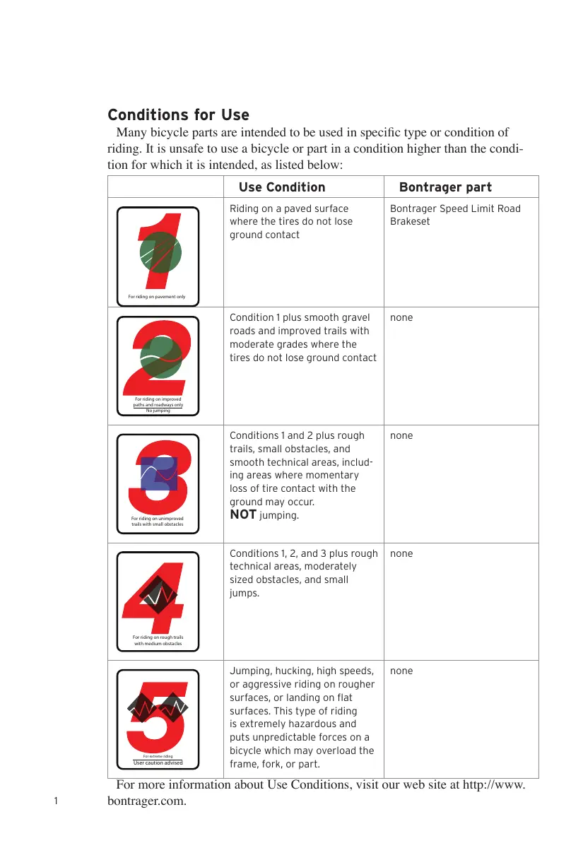
Conditions for Use
Many bicycle parts are intended to be used in specific type or condition of riding. It is unsafe to use a bicycle or part in a condition higher than the condition for which it is intended, as listed below:
| Use Condition | Bontrager part | |
| For riding on pavement only | Riding on a paved surface where the tires do not lose ground contact | Bontrager Speed Limit Road Brakeset |
| For riding on improved paths and roadways onlyNo jumping | Condition 1 plus smooth gravel roads and improved trails with moderate grades where the tires do not lose ground contact | none |
| For riding on unimproved trails with small obstacles | Conditions 1 and 2 plus rough trails, small obstacles, and smooth technical areas, including areas where momentary loss of tire contact with the ground may occur. NOT jumping. | none |
| For riding on rough trails with medium obstacles | Conditions 1, 2, and 3 plus rough technical areas, moderately sized obstacles, and small jumps. | none |
| For riding on rough trails with medium obstaclesUser caution advised | Jumping, hucking, high speeds, or aggressive riding on rougher surfaces, or landing on flat surfaces. This type of riding is extremely hazardous and puts unpredictable forces on a bicycle which may overload the frame, fork, or part. | none |
For more information about Use Conditions, visit our web site at http://www.bontrager.com.
Thank you for purchasing Bontrager Speed Limit Road Brakesets
These caliper (side-pull) brakes are designed for Condition 1 road riding. Caliper brakes come in different reach distances (the distance from the brake mounting hole to the rim.) If these brakes do not offer the correct adjustment to fit your bike, consult your Bontrager dealer.
If the brakes are already installed on your bike, please read the following Checklist and Safety information. If the brakes are not installed, the Installation instructions begin on page 5.
Figure 1 Bontrager Speed Limit Road Brakeset
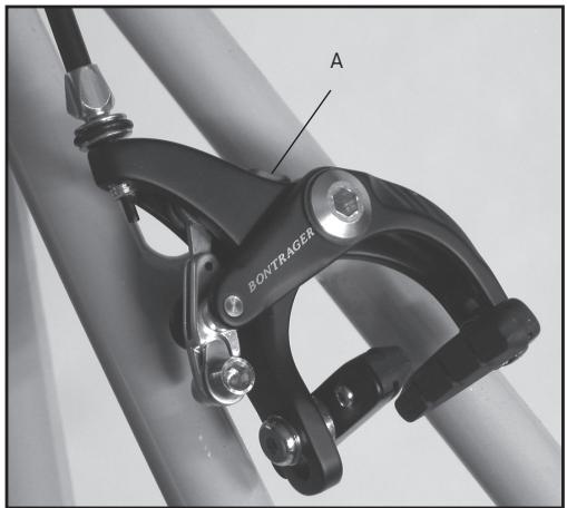
A: Brake opening lever
BEFORE EVERY RIDE: CHECKLIST
Before every ride, check your bicycle and its brakes. If your brakes do not pass inspection, readjust the brake system or take your bicycle to your dealer for service.
WARNING
If your brakes are not working properly, you can lose control and fall. Inspect the brakes thoroughly before every ride. Do not ride the bicycle until any problem has been corrected.
Squeeze each brake lever toward the handlebar to make sure the brake moves freely and stops the bicycle. If the brake lever can be pulled to the handlebar, the brake is too loose (make sure the brake opening lever, Figure 1, is closed).
When the brakes are not applied, the brake pads should be 1 to 2mm from the
rim. If the brake pads are too close to the rim, the brake is too tight. Brake pads should be aligned with the rim surface (Figure 2). If the brakes are not properly adjusted, follow the instructions in the Adjustment section of this manual or take your bicycle to your dealer for service.
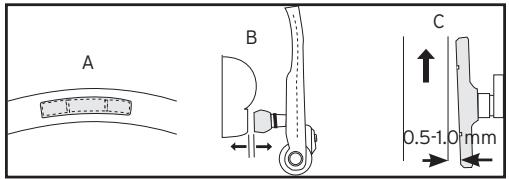
Figure 2- Brake pad alignment
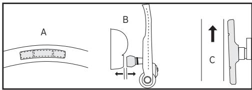
A: Brake pad aligned with rim surface
B: Brake pad and rim parallel
C: Brake pad toe-in
USE YOUR BRAKES CAREFULLY
Always keep a safe stopping distance between you and other vehicles or objects. Adjust stopping distances and braking forces to suit riding conditions.
Do not overuse the front-wheel brake
If your bicycle has two hand brakes, apply both brakes at the same time. Over-use or misuse of a front-wheel brake, such as using only the front-wheel brake in an emergency, could cause the rear wheel to lift from the ground which could cause you to lose control (Figure 3).
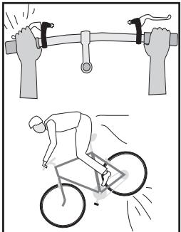
Figure 3- Overuse of the front-wheel brake can cause the rear wheel to lift
WARNING
Applying sudden or excessive stopping force with the front-wheel brake may cause the rear wheel to lift off the ground or the front wheel to slip out from under you, which can cause you to lose control and fall. Apply both brakes at the same time, and shift your weight backward on the bicycle while braking.
Make sure your brakes meet your needs
Many models of modern brakes are very powerful; they are designed to stop a bicycle in wet or muddy conditions. If you feel your brakes are too powerful for your riding needs, take your bicycle to your dealer for adjustment or replacement of the braking system.
Be careful when riding in wet conditions
No brakes, whatever their design, work as effectively in wet weather as they do in dry. Even properly aligned, lubricated, and maintained brakes require greater lever pressure and longer stopping distances in wet weather; anticipate the extra distance it will take to stop.
INSTALLATION INSTRUCTIONS

The correct installation of your new Bontrager brakes is critical to your safety, so this work should be performed only by an experienced mechanic. The installation portion of these instructions is written for an experienced mechanic. If you are not sure of your ability to correctly install these brakes, have the brakes installed by your Bontrager dealer.
Included items:
- Front brake (with longer attachment bolt)
Rear brake (with shorter attachment bolt) - Attachment nuts, 2 (Figure 4)
Note: Some bicycles require a longer attachment nut. The nut should have at least six full turns of thread engagement. If necessary, consult your dealer about a longer nut.
- Castellated washers, 2
Tools required:
- 4, 5, and 6mm allen wrench
- Sharp probe (dental pick, sharpened spoke, etc.)
Housing cutters, or dikes - File or bench grinder
To prepare the bicycle for the installation
- Remove the handlebar tape.
- Remove the old brakes, cables, and housings.
To attach the brakes
- Remove the brake nut from the brake, but leave the castellated washer on the attachment bolt.
- With the rear brake (shorter attachment bolt), insert the brake attachment bolt through the brake mounting hole in the frame.
- Install the attachment nut, but do not tighten fully (Figure 5).
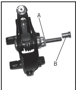
Figure 4 Brake attachment parts
A: Castellated washer
B: Attachment nut
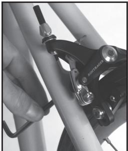
Figure 5 Tightening the attachment nut
To prepare the brake housing
- Check the length of the housings.
If appropriate, use the old housing as a guide. The correct length of housing should allow full rotation of the handlebar and should not snag on the front reflector.
- Square the ends of the housings with a file or bench grinder.
If necessary, use a sharp probe to open the end of the housing liner to eliminate cable friction.
Where appropriate, install brake housing end caps. The special housing end caps with the extension are intended to guide the cable through the barrel adjuster (Figure 7).
To install the brake cables
- Where the cables run inside housing, lubricate them with a light grease or heavy oil.
- Slide the housings up the cables until the housings are firmly engaged in the lever.
Some brake levers require special housing ferrules or cable guides inside the lever. If unsure, consult your dealer.
- Thread the cable through the stops, cable protector donuts, and housing to the cable clamp bolt.
- Make sure the leaded end of the cable is properly seated in the brake lever (Figure 6).
- Attach the cable to the brake and tighten the cable clamp bolt (Figure 7) to 50 - 70lb· in (5.7 - 7.9Nm)
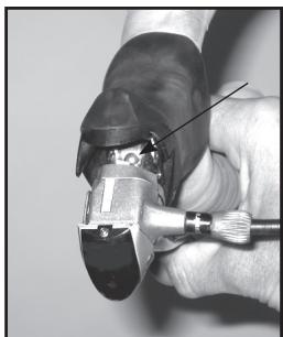
Figure 6 Leaded end of cable in the brake lever
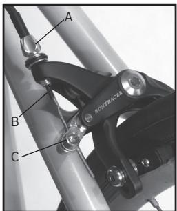
Figure 7 Cable guide parts
A: Barrel adjuster
B: Extended housing ferrule
C: Cable clamp bolt
ADJUSTMENT INSTRUCTIONS

Brake pad holders have a front and rear. If the holder is facing the wrong direction, the pad could slide from the holder when the brake is applied. Make sure the Bontrager logo on the brake shoe holder is facing up and that the open end of the holder faces the rear of the bicycle.
To adjust the brakes
- Center the brake. Loosen the brake attachment bolt, move the brake until both pads are the same distance from the rim, and retighten the attachment bolt to 70-85 lb-in (7.9-9.6 Nm).
Small centering adjustments can be made by simply rotating the center bolt with a 6mm allen wrench (Figure 8).
- Loosen the brake pad attachment bolt.
- Align the pad, and squeeze the brake (or the brake lever) to hold the pad aligned against the rim (Figure 9).
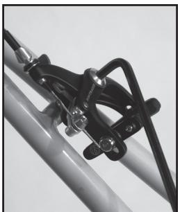
Figure 8 Center the brake
Toe-in prevents squealing, and is usually only needed with new brake pads. To achieve correct toe-in, you can put a business card between the rim and the trailing edge of the brake pad prior to
holding the pad against the rim.
- Tighten the pad attachment bolt (Figure 10) to 40-60 lb-in (4.5-6.8 Nm).
- Repeat for the other pad.
With new cables or housing, 'stretch' the cables (compress the
housing). Apply the brake fully while you 'stroke' the housing. Use your fingers to create a tighter-radius curve in the housing, then move the curve back and forth along the entire length of each piece of housing.
Figure 9- Brake pad alignment
A: Brake pad aligned with rim surface
B: Brake pad and rim parallel
C: Brake pad toe-in
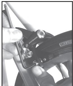
Figure 10 Pad attachment bolt
To adjust the brakes (cont.)
- Turn the barrel adjuster (Figure 11) out one or two turns. Turn the barrel adjuster locknut to hold the adjustment.
If the pads are not 1 - 2mm from the rim, reattach the brake cable to provide the proper clearance.
- Tape the handlebar.
To function check the brakes
-
Make sure the pads meet the rim squarely (with a slight toe-in for new brake pads), and that the pads cannot rotate.
-
Check that the pads cannot contact the tire during any part of the wheel rotation.
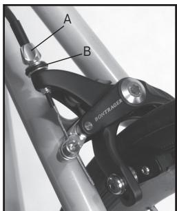
Figure 11 Cable adjustment parts
A: Barrel adjuster
B: Locknut
- Apply the brake lever fully and make sure the lever cannot contact the handlebar.
- Check that the cable does not slip in the cable clamp.
- Check that the brake applies adequate stopping power.
- Check that the brake does not squeal when applied.
BONTRAGER LIMITED WARRANTY
Bontrager warrants each new Bontrager component or wheelset against defects in workmanship and materials:
For five years
- All Bontrager components and accessories, except consumables such as tires and inner tubes.
For one year
- Bontrager consumables such as tires and inner tubes.
This warranty does not cover
Normal wear and tear
- Improper assembly
- Improper follow-up maintenance
- Installation of parts or accessories not originally intended for or compatible with the Bontrager fork, components, or wheelsets as sold
- Damage or failure due to accident, misuse, abuse, or neglect
Labor charges for part replacement or changeover
This warranty is void in its entirety by any modification of the wheelset or components.
This warranty is expressly limited to the repair or replacement of a defective item and is the sole remedy of the warranty. This warranty extends from the date of purchase, applies only to the original owner, and is not transferable. Bontrager is not responsible for incidental or consequential damages. Some states do not allow the exclusion of incidental or consequential damages, so the above exclusion may not apply to you.
Claims under this warranty must be made through an authorized Bontrager dealer. Proof of purchase is required.
This warranty gives the consumer specific legal rights, and those rights may vary from place to place. This warranty does not affect the statutory rights of the consumer.
Carbon crash replacement policy
Assessing any damage done to a carbon fiber part requires more experience than is needed to inspect metal parts. If you crash or impact your bike and the force of the impact is absorbed by a carbon part, we strongly encourage you to replace the part, even if there are no indications of damage.
If such a crash or impact occurs, Bontrager offers a crash replacement program for carbon parts, substantially reducing any replacement cost. To take advantage of this program, contact us using the information listed in the front of this manual, and ask for the Warranty department.
LISEZ CE MANUEL AVANT D'UTILISER VOTRE VÉLO
Attn: Customer Service
http://www.bontrager.com
801 W. Madison Street
Instructions d'st installation. 4
- 2 rondelles à créèaux (castellated means it has separated notches or teeth)
Outils requisite
Atn: Customer Service
http://www.bontrager.com
801 W. Madison Street
Waterloo, Wisconsin 53594, Estados Unidos

- 2 arandelas dentadas (castellated means it has separated notches or teeth)
Herramientos necessities:
-llavesallen de 4,5y6mm
- Sonda aflida (dentada, radio aflido, etc.)
Cúters de revestimiento o diques
- Esmeriladora
Attn: Customer Service
801 W. Madison Street
Waterloo, Wisconsin 53594, USA
920.478.4678
http://www.bontrager.com
