
TD 309 - Turntable THORENS - Free user manual and instructions
Find the device manual for free TD 309 THORENS in PDF.
| Product type | Turntable |
| Brand | THORENS |
| Model | TD 309 |
| Dimensions (L x H x D) | 470 x 125 x 430 mm |
| Weight | 6.5 kg |
| Power supply | 12 V DC/AC power supply, min. 6 W; standby consumption < 0.5 W |
| Operation | Manual (no automatic stop) |
| Drive | Internal flat belt |
| Motor | Electronically controlled DC motor |
| Rotation speeds | 33 1/3 and 45 rpm; adjustment ±5% |
| Platter | Quartz glass, 12 inches (30.5 cm), 2.3 kg |
| Tonearm | Thorens TP 92; effective length 232.8 mm; fixed offset angle 23.6°; dynamic mass approx. 18 g |
| Phono cartridge | AT-95 B (pre-installed, spacing 12.5 mm) |
| Overhang | Adjustable on the cartridge holder ±2.5 mm; additional ±3 mm and azimuth ±5° at rear end |
| Tracking force | Recommended 18-20 mN (1.8-2.0 g) for TP 92 / AT-95 B |
| Antiskating | Integrated magnet, adjustable via screw |
| VTA adjustment | Possible by raising/lowering the arm (22 mm lock nut and adjustment nut) |
| Phono input | Requires a phono preamp if amplifier has no phono input (Thorens MM 001 or MM 005) |
| Included accessories | Drive belt, glass platter, felt mat, balancing masses, counterweight, power supply, cinch cable, ground wire, 17 cm disc adapter, turntable scale, spirit level |
| Maintenance | Clean the belt with glass cleaner or alcohol; replace the belt after a few years |
| Safety instructions | Do not open the chassis; do not expose to rain or moisture |
| General information | Made in Germany; product registration at thorens.de/register; after-sales service via thorens.com |
Frequently Asked Questions - TD 309 THORENS
User questions about TD 309 THORENS
0 question about this device. Answer the ones you know or ask your own.
Ask a new question about this device
Download the instructions for your Turntable in PDF format for free! Find your manual TD 309 - THORENS and take your electronic device back in hand. On this page are published all the documents necessary for the use of your device. TD 309 by THORENS.
USER MANUAL TD 309 THORENS
natural_image
Red THORENS TD 309 radio with a circular disc and mechanical tool (no visible text or symbols on the device body)Inhalt
SAFETY INSTRUCTIONS 22
UNPACKING 23
SETUP AND ASSEMBLY 24
TURNTABLE ADJUSTMENTS 27
CONNECTIONS 28
TONEARM AND PICK-UP CARTRIDGE 30
TRACKING FORCE 31
ANTI-SKATING FORCE (BIAS) 32
FURTHER TONEARM ADJUSTMENTS 33
OPERATION 35
TECHNICAL SPECIFICATIONS 36
CUSTOMER SERVICE 37
Sommaire
CONSIGNES DE SECURITE 38
DEBALLAGE 39
INSTALLATION ET MONTAGE 40
REGLAGES DE L'ENTRAINEMENT 43
RACCORDEMENT 44
BRAS ET CELLULE DE LECTURE 46
FORCE D'APPUI 47
FORCE ANTISKATING 48
AUTRES REGLAGES DU BRAS 49
UTILISATION DE LA PLATINE 51
CARACTERISTIQUES TECHNIQUES 52
INFORMATIONS SERVICE APRES-VENTE 53
Sicherheitshinweise
BITTE VOR DER ERSTMALIGEN INBETRIEBNAHME AUFMERKSAM LESEN!
VORSICHT
natural_image
3D mechanical component diagram showing a red body with labeled parts and directional arrows (no readable text or symbols)natural_image
3D rendering of a mechanical pulley system with red coil and black shaft, no visible text or symbols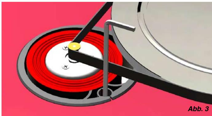
natural_image
Close-up of a mechanical component with red and white concentric rings, no visible text or symbolsnatural_image
Red Thorens 309 radial disc with CD/DVD disc and mechanical tool (no text or symbols on the device itself)
natural_image
Red and black electronic device with circular components and a textured surface (no visible text or symbols)natural_image
3D rendering of a red THORES TD 308 quartz cutting tool with labeled components and measurement scale (no text or symbols on the device itself)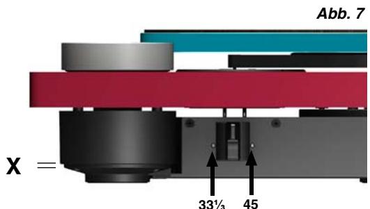
text_image
Abb. 7 X = 33½ 45Anschluss
natural_image
Close-up of a mechanical device with a black and red horizontal panel, a circular knob, and an arrow pointing to the knob (no text or symbols visible)Abb. 8
Anschluss
natural_image
3D mechanical assembly diagram showing a layered component with orange and red ports and a white arrow indicating a specific point (no text or symbols present)natural_image
Mechanical assembly of a Thorens TP 92 sensor with attached clamp and shaft (no text or symbols visible)Auflagekraft
natural_image
Mechanical assembly diagram showing a rotating tool with a labeled component (no readable text or symbols)natural_image
3D mechanical assembly diagram showing a lathe setup with labeled components and directional arrows (no readable text or symbols)natural_image
Mechanical assembly diagram showing a metal clamp and mechanical component with an arrow indicating direction (no text or symbols present)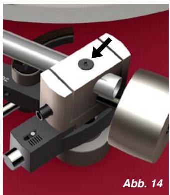
natural_image
Mechanical assembly component with metallic parts and a black arrow indicating a specific point (no text or symbols present)natural_image
Close-up of a red mechanical component with a bolt and pipe, labeled Abb. 15 (no readable text or symbols beyond label)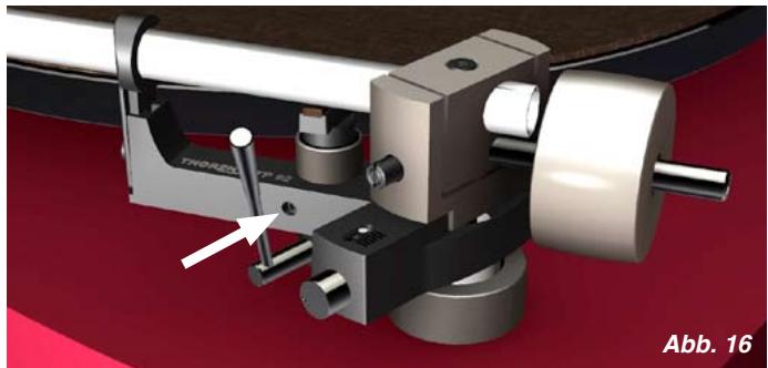
natural_image
Mechanical assembly diagram showing a rotating tool with labeled components and an arrow indicating a specific part (no readable text or symbols)natural_image
Close-up of a mechanical component with red and black stripes, showing a small bracket and a white arrow pointing to it (no text or symbols visible)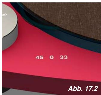
text_image
45 0 33 Abb. 17.2
natural_image
Mechanical assembly diagram showing a rotating shaft and housing with a white arrow indicating motion direction (no text or symbols)Technische Daten
To reduce risk of electric shock, do not remove the cover (or back). No user-serviceable parts inside.
WARNING
TO PREVENT FIRE OR SHOCK HAZARD, DO NOT EXPOSE THIS APPLIANCE TO RAIN OR MOISTURE.

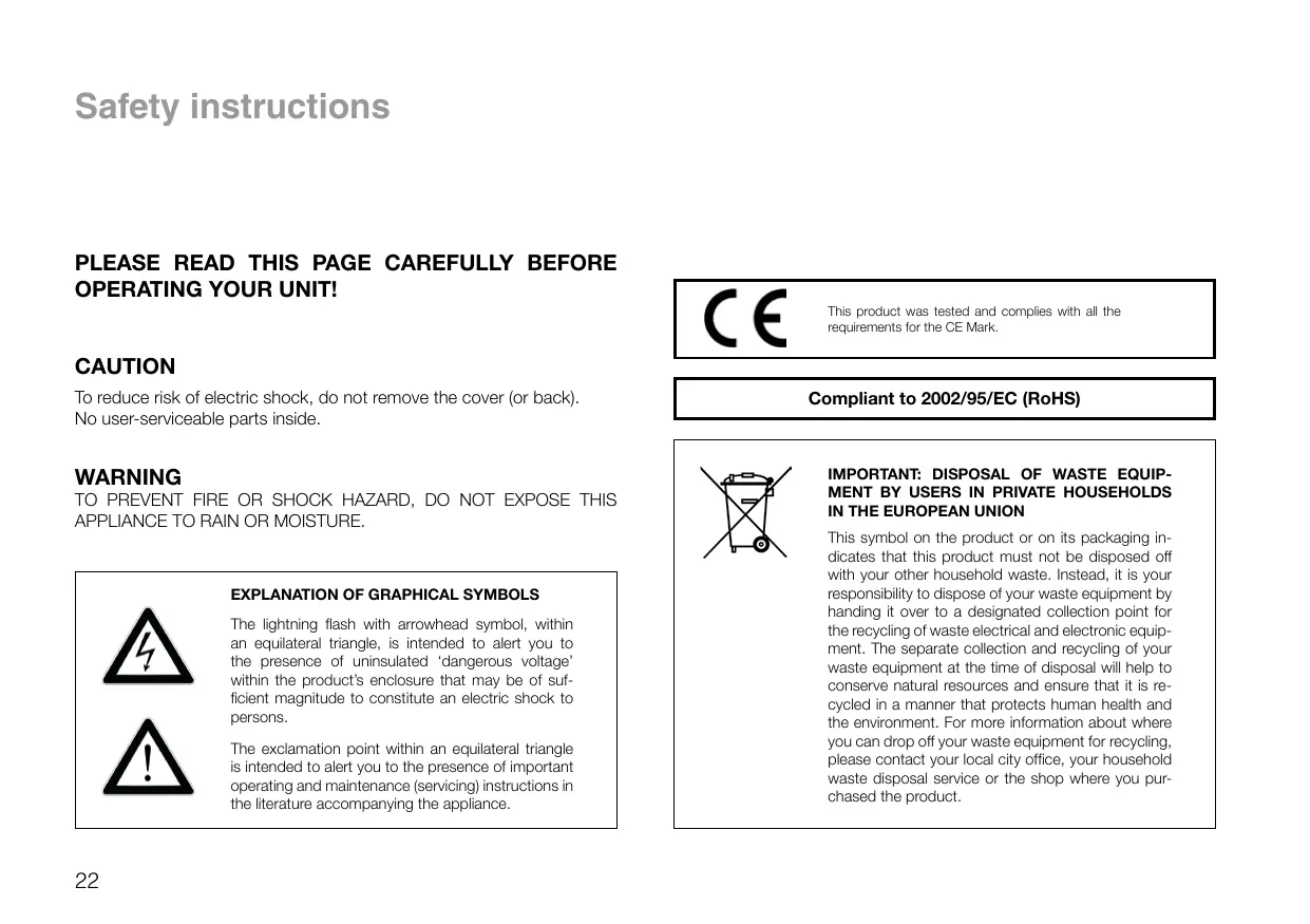
EXPLANATION OF GRAPHICAL SYMBOLS
The lightning flash with arrowhead symbol, within an equilateral triangle, is intended to alert you to the presence of uninsulated ‘dangerous voltage’ within the product’s enclosure that may be of sufficient magnitude to constitute an electric shock to persons.

The exclamation point within an equilateral triangle is intended to alert you to the presence of important operating and maintenance (servicing) instructions in the literature accompanying the appliance.

This product was tested and complies with all the requirements for the CE Mark.
Compliant to 2002/95/EC (RoHS)

IMPORTANT: DISPOSAL OF WASTE EQUIPMENT BY USERS IN PRIVATE HOUSEHOLDS IN THE EUROPEAN UNION
This symbol on the product or on its packaging indicates that this product must not be disposed off with your other household waste. Instead, it is your responsibility to dispose of your waste equipment by handing it over to a designated collection point for the recycling of waste electrical and electronic equipment. The separate collection and recycling of your waste equipment at the time of disposal will help to conserve natural resources and ensure that it is recycled in a manner that protects human health and the environment. For more information about where you can drop off your waste equipment for recycling, please contact your local city office, your household waste disposal service or the shop where you purchased the product.
Unpacking
Carefully remove the turntable and all accessories from the box. Check that the following items are included:
1 x base with sub-platter and tonearm
1 x Thorens drive belt
1 x platter
1 x felt mat
1 x balance weight
1 x tonearm counterweight
1 x plug-in power supply and power cable
1 x RCA phono cable
1 x earth wire
1 x adapter for 7-inch records
1 x stylus balance
1 x spirit level
Please keep the packaging for future transport. Always replace the transit screws before re-packing and shipping.
natural_image
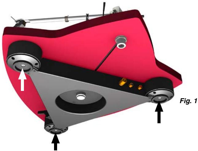
3D mechanical component diagram showing a red body with labeled parts and directional arrows (no text or symbols beyond labels)The three transit screws inside the sub-chassis feet need to be removed before the turntable can be set up. → Fig. 1
The suspension in each sub-chassis foot is factory-adjusted and will not need to be readjusted unless the weight of the turntable is altered (e.g. through the use of stabilisers or heavy platter mats). → Page 27
Setup and Assembly
Place the turntable on a rigid support and use the supplied spirit level to make sure that it is perfectly horizontal. If necessary, readjust the suspension system. → Page 27
Thorens turntables are relatively resistant to vibration. However, vibration can have adverse effects on any turntable, particularly if a high-quality pick-up cartridge is used. You should therefore place the turntable on a sturdy piece of furniture, ideally at some distance from the loudspeakers.
older houses with beam floors, however, this may not be enough to properly isolate the turntable from vibrations. In this case we recommend placing the turntable on a wall shelf that is attached to a supporting wall.
When siting the turntable, make sure that it is at a reasonable distance from any existing electronic equipment (such as amplifiers, receivers or CD players) so as to avoid electromagnetic interference in the pick-up cartridge, which could cause a hum in the signal. The same applies to the cable connecting the turntable to the amplifier.
You can detect and eliminate electromagnetic interference by changing the position of the turntable with respect to other pieces of equipment.
Setup and Assembly
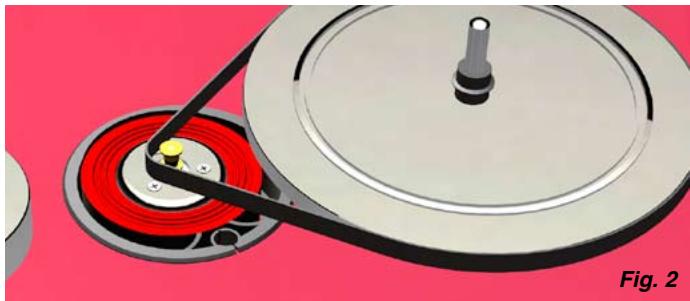
Loop the drive belt around the sub-platter and then around the motor pulley. → Fig. 2
Avoid oil or grease coming into contact with the belt, pulley or sub-platter. If necessary, these parts can be cleaned with glass cleaner or pure alcohol and a lint-free cloth.
The belt tension is factory-adjusted. If it needs to be re-adjusted (e.g. to compensate for gradual belt stretch), loosen the locking screw of the eccentric motor support ring and carefully rotate the ring. → Fig. 3
If the belt tension is changed, the motor speed will need to be reset. → Page 27
The drive belt should be replaced every few years. Thorens replacement belts are available from any Thorens dealer or distributor.
natural_image
3D illustration of a mechanical device with red pulley and black shaft, no text or symbols present
natural_image
Close-up of a mechanical component with red and white concentric rings, no visible text or symbolsSetup and Assembly
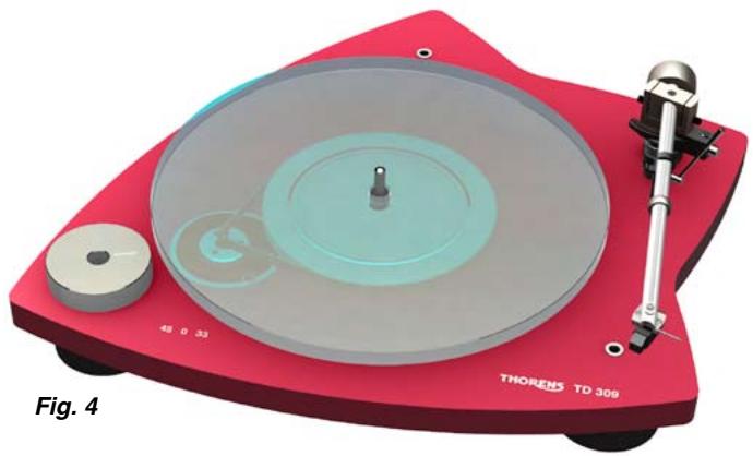
Place the glass platter onto the sub-platter (frosted side down). → Fig. 4
Then place the felt mat on the platter. The soft mat prevents slippage during playback and minimises wear and tear on your records.
natural_image
Red THORENS TD 309 radio disc with visible mechanical components and control knob (no text or symbols on the device itself)
natural_image
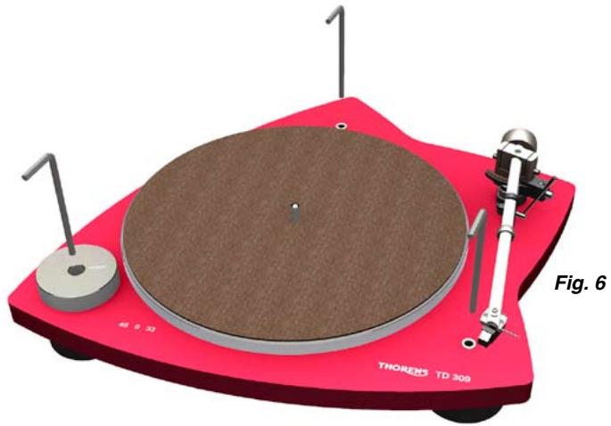
Red and black electronic device with circular components and a textured surface (no visible text or symbols)Place the balance weight on the base so that it sits exactly above the front left sub-chassis foot (this is its default position). Move the balance weight for fine adjustment, determining the best position through listening tests. → Fig. 5
This almost completes the assembly of the turntable. The only part missing now is the tonearm counterweight. → Page 30
Turntable adjustments
The suspension in each sub-chassis foot can be adjusted from above with the help of a 5-mm hex key ( Abb. 6). The inner cylinder of each foot should protrude by 2 mm at position X. Fig. 7
The suspension system is factory-adjusted. It should be readjusted if the weight of the turntable is altered (e.g. through the use of stabilisers or heavy platter mats) or if the supporting surface is not perfectly level.
The platter speed can be adjusted by turning the adjustment screw to the left or right of the speed switch (for 33½ and 45 rpm, respectively). → Fig. 7
The platter speeds are factory-adjusted. Any readjustment of the speeds should be checked with the help of a test record or a strobe disc.
Please also refer to “Belt Tension” → Page 25
natural_image
3D rendering of a red THORES TD 308 quartz cutting tool with a circular base and mechanical arm (no text or symbols on the device itself)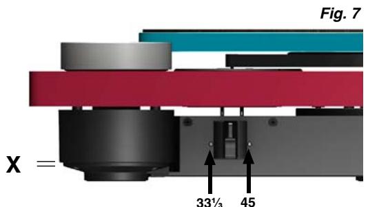
text_image
Fig. 7 X = 33½ 45Connections
The turntable comes with a universal plug-in power supply that will accommodate all common mains voltages.
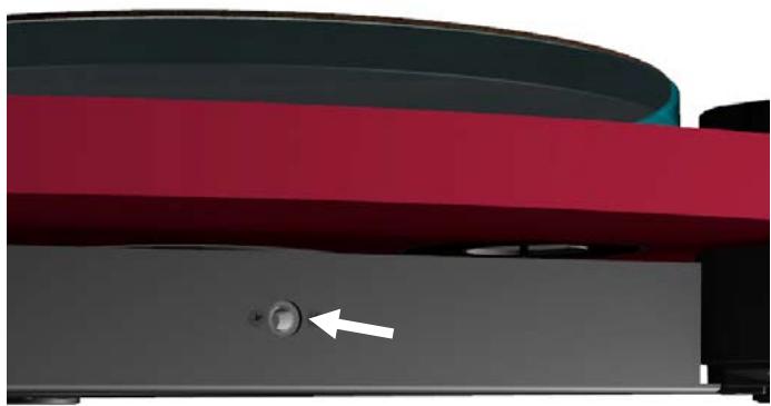
Plug the low-voltage connector of the power supply into the appropriate socket on the turntable and then plug the power supply into the mains socket. → Fig. 8
If the turntable is to be powered by mains voltages other than those specified, it may be necessary to use an adapter. Please contact your Thorens dealer or distributor for further advice.
natural_image
Close-up of a mechanical component with a white arrow pointing to a button (no text or symbols visible)Fig. 8
Connections
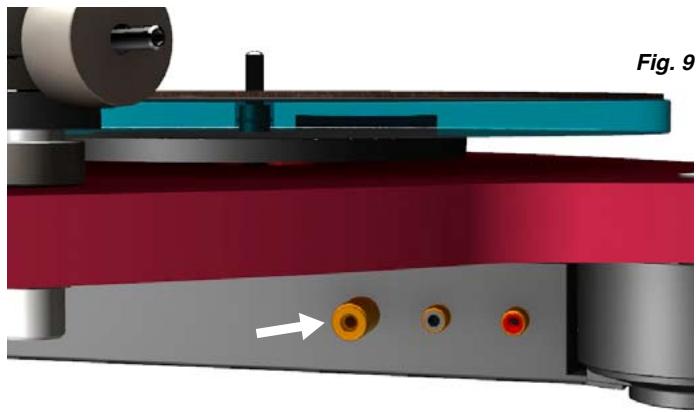
Use the supplied RCA phono cable to connect the turntable output to the phono input of your amplifier. Check that all plugs are connected with the correct polarity. → Fig. 9
In accordance with RIAA standards, vinyl records are cut with pre-emphasis. The operation of a turntable therefore requires the use of a phono stage for equalisation. If your amplifier does not have a phono input, you will need to connect a dedicated phono stage such as the Thorens MM 001 or MM 005 between the turntable and the amplifier. Please contact your Thorens dealer or distributor for further advice.
The earth wire is used to establish an electrical connection to earth. Connect the wire to the earth screws on the turntable ( Fig. 9, indicated by an arrow) and the amplifier. If your amplifier does not have an earth screw, you can attach the wire to the side of an unused input socket.
natural_image
3D mechanical assembly diagram showing a layered component with orange and red ports and a white arrow indicating a specific point (no text or symbols present)If you can hear a hum in the speakers that increases as you increase the overall volume, then the earth connection may be faulty. Make sure that the earth wire is firmly connected. If the problem persists, try connecting the wire to a different spot.
Tonearm and Pick-Up Cartridge
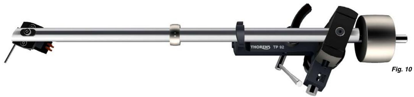
Your Thorens TD 309 turntable is delivered with a pre-installed TP 92 tonearm and an AT-95 B pick-up cartridge. → Fig. 10
The tonearm is factory-adjusted; however, to avoid damage, the tonearm counterweight is removed for shipping. Screw the counterweight onto the rear end of the tonearm and adjust the tracking force. → Page 31
The TP 92 tonearm can accommodate most pick-up cartridges with a distance of 12.5 mm ( 12 ) between the mounting holes.
To connect the pick-up cartridge, push the four colour-coded cartridge tags onto the cartridge pins.
If the cartridge pins are not colour-coded, connect them as follows:
R right channel (signal) → red
G right channel (earth) → green
L left channel (signal) → white
G left channel (earth) → blue
natural_image
Mechanical assembly diagram of a Thorens TP 92 device with lever and mounting bracket (no text or symbols on the device itself)Tracking Force
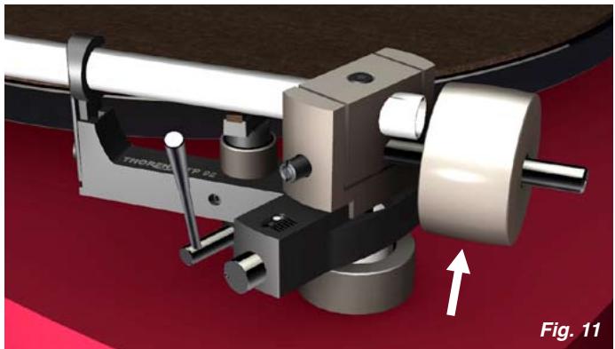
The tracking force can be adjusted by rotating the tonearm counterweight ( Fig. 11). The closer the counterweight is to the cartridge, the higher the tracking force.
The correct tracking force can be set with the help of the stylus balance. Lower the tonearm lift, move the tonearm out over the platter and carefully lower it until the stylus of the pick-up cartridge comes to rest on the stylus balance. The stylus guard must be removed for this procedure.
Great care should be taken to avoid damaging the stylus.
The recommended tracking force range for the TP 92/AT-95 B combination is 18 to 20 mN (which corresponds to a weight of 1.8 to 2.0 g).
natural_image
Mechanical assembly diagram showing a rotating tool with a labeled component (no readable text or symbols)Do not move the ring that sits around the middle of the tonearm tube ( Page 30, Fig. 10). It serves as a vibration damper and is effective only at its original position.
Anti-Skating Force (Bias)
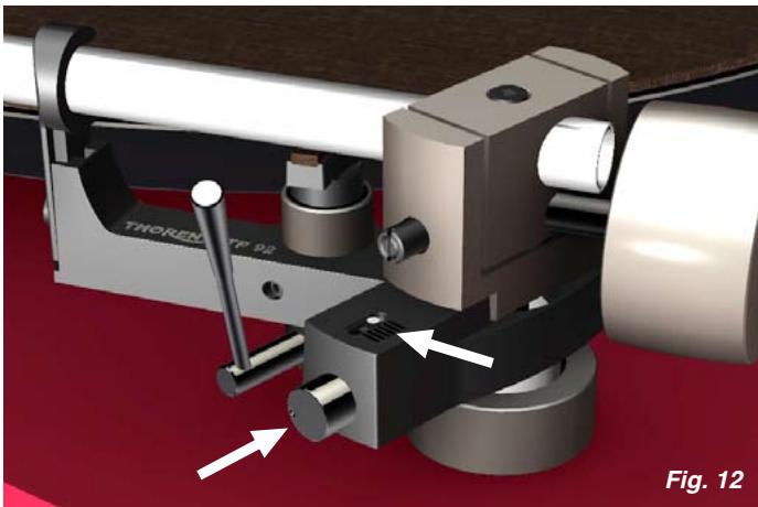
The interaction of stylus friction and cartridge bearing forces produces a force which pulls the tonearm towards the centre of the record (referred to as skating force). This force can be offset with the help of anti-skating force, which, in the case of the TP 92, is produced by a magnet incorporated into the tonearm.
The anti-skating force is factory-adjusted. If necessary, it can be readjusted with the help of an adjustment screw. → Fig. 12
Turn the adjustment screw anti-clockwise to increase, and clockwise to decrease the anti-skating force. The white dot above the adjustment screw indicates the setting.
The amount of anti-skating force required depends on the type of pick-up cartridge used. If you change the cartridge for a different type, use a test record to determine how much anti-skating force is required.
natural_image
3D mechanical assembly diagram showing a cam or caliper with labeled components and directional arrows (no readable text or symbols)Further Tonearm Adjustments
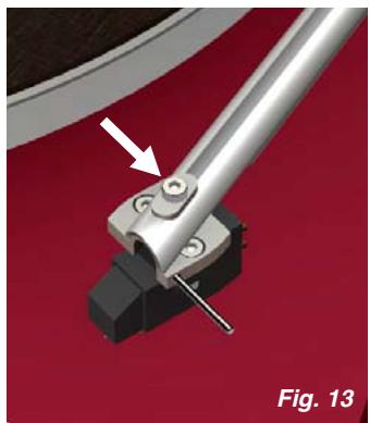
The tonearm headshell allows an overhang adjustment of ±2.5 mm to be made. To adjust overhang, loosen the screw holding the headshell and move the headshell as required. → Fig. 13
A screw at the rear of the tonearm allows a further overhang adjustment of ±3 mm as well as an azimuth adjustment of ±5^ . The screw is recessed into the top of the bearing housing and can be loosened with a 2-mm hex key. → Fig. 14
The vertical tracking angle (VTA) can be adjusted by raising or lowering the tonearm. → Page 34
Take care not to over-tighten the screws after making adjustments.
natural_image
Mechanical assembly diagram showing a metal clamp and mechanical component with an arrow indicating a specific part (no text or symbols present)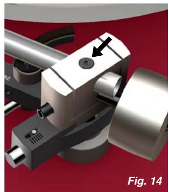
natural_image
Mechanical assembly component with metallic parts and a black arrow indicating a specific point (no text or symbols present)Further Tonearm Adjustments
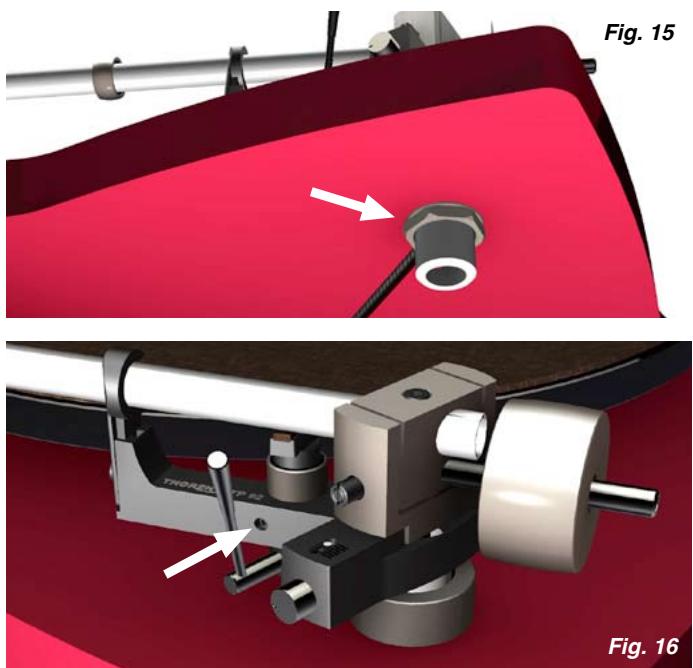
The vertical tracking angle (VTA) can be adjusted by raising or lowering the entire tonearm. Loosen the lock nut on the underside of the turntable with a 22-mm jaw spanner; then turn the adjustment ring above the base to raise or lower the tonearm as required. → Fig. 15
If the VTA is changed, the tonearm lift will need to be to be readjusted. Loosen the locking screw on the tonearm lift with a 1.5-mm hex key and carefully raise or lower the entire lift. → Fig. 16
The tonearm tube should be parallel to the platter surface. Small adjustments of the VTA or the tonearm lift height can have a large effect. After making any changes, you should therefore always check whether there is enough clearance (at least 1 mm) between the cartridge and the record (when the lift is engaged) and between the tonearm lift pad and the tonearm tube (when the lift is disengaged).
Operation
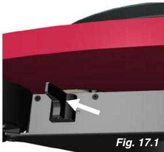
The on/off switch is located near the front left foot underneath the base of the turntable. This switch is also the speed selector. There are two speeds: 33½ rpm (for LPs) and 45 rpm (for singles). The middle position is the "off" position. → Fig. 17
To play a record, first start the turntable by selecting the appropriate speed. Then engage the tonearm lift ( Fig. 18) by lifting its lever, position the pick-up cartridge over the run-in groove or the desired track and lower the tonearm lift.
The TD 309 does not feature an automatic shut-off mechanism. Therefore, as soon as the stylus has reached the run-out groove, engage the tonearm lift and switch the turntable off.
natural_image
Close-up of a mechanical component with a white arrow pointing to a small black part, labeled 'Fig. 17.1' (no readable text or symbols beyond label)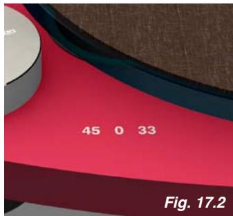
text_image
45 0 33 Fig. 17.2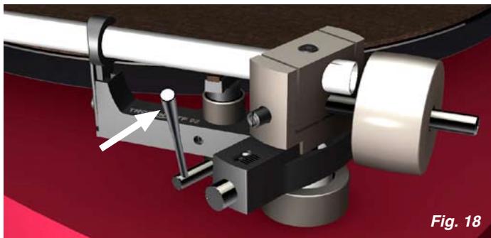
natural_image
Mechanical assembly diagram showing a rotating shaft and housing with a white arrow indicating a specific component (no text or symbols present)Technical Specifications
| Mode of operation | Manual |
| Drive system | Belt drive (flat belt around sub-platter) |
| Motor | Servo-controlled DC motor |
| Speeds | 33 13 , 45 rpm |
| Adjustment range | ±5 % |
| Speed change | Electronic |
| Platter | 12” / 2.3 kg (glass) |
| Power supply | External plug-in power supply, 12 V DC/AC, 6 W min.; consumption when off: 0.5 W max. |
| Dimensions | 470 x 125 x 430 mm (W x H x D) |
| Weight | 6.5 kg |
| Tonearm | Thorens TP 92 |
| Effective length | 232.8 mm (9,1”) |
| Overhang | 17.8 mm (variable) |
| Offset angle | 23.6° (fixed) |
| Effective mass | approx. 18 g |
Technical specifications subject to change without notice. Made in Germany.
Customer Service
Your Thorens dealer or distributor will be happy to assist you if you have any questions regarding your new turntable or experience any problems. For a list of Thorens distributors, please visit → www.thorens.com or contact us directly:
→ www.thorens.com/contact
Register your product with Thorens to receive up-to-date information and special offers. You can use the registration card included with the product or visit our website:
→ www.thorens.de/register
natural_image
3D mechanical component diagram labeled Fig. 1, showing a red body with gears and mounting points (no text or symbols beyond label)natural_image
3D illustration of a mechanical device with red pulley and black lever, labeled Fig. 2 (no text or symbols on the diagram itself)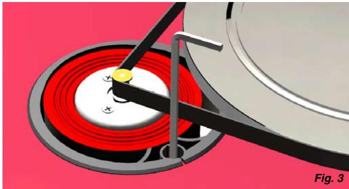
natural_image
Close-up of a mechanical component with red circular base and black lever, no visible text or symbolsnatural_image
Red THORENS TD 309 radio disc with visible mechanical components and control knob (no text or symbols on the device itself)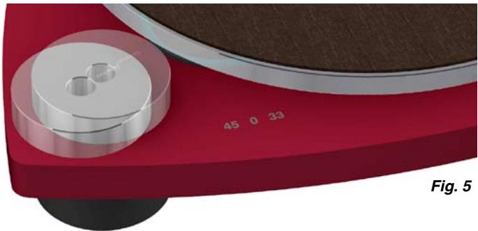
natural_image
Red and black electronic device with circular components and a textured surface (no visible text or symbols)natural_image
3D rendering of a red THORES TD 308 quartz cutting tool with a circular base and mechanical arm (no text or symbols on the device itself)
text_image
Fig. 7 X = 33½ 45Raccordement
natural_image
Close-up of a mechanical component with a white arrow pointing to a button (no text or symbols visible)Fig. 8
Raccordement
natural_image
3D mechanical assembly diagram showing a layered component with orange and red ports and a white arrow indicating direction (no text or symbols)natural_image
Mechanical assembly of a Thorens TP 92 device with lever and clamping mechanism (no text or symbols visible)Force d'appui
natural_image
Mechanical assembly diagram showing a rotating tool with a labeled component (no readable text or symbols)natural_image
3D mechanical assembly diagram showing a cam or caliper with labeled components and directional arrows (no readable text or symbols)natural_image
Mechanical assembly diagram showing a metal clamp and mechanical component with an arrow indicating direction (no text or symbols)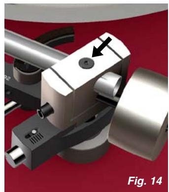
natural_image
Mechanical assembly component with metallic parts and a black arrow indicating a specific feature (no text or symbols present)natural_image
Technical illustration of a mechanical assembly with labeled components, showing two views (Fig. 15 and Fig. 16) with arrows indicating parts of the component.natural_image
Close-up of a mechanical component with a white arrow pointing to a small black part, set against a red and black striped background (no text or symbols visible)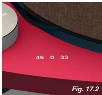
text_image
45 0 33 Fig. 17.2
natural_image
Mechanical assembly diagram showing a rotating shaft and housing with a tool, labeled Fig. 18 (no text or symbols on the diagram itself)→ www.thorens.com/contact