
SRC 4034 FC - Audio Mixer PEAVEY - Free user manual and instructions
Find the device manual for free SRC 4034 FC PEAVEY in PDF.

| Product Type | Audio Mixing Console |
| Brand | Peavey |
| Model | SRC 4034 FC |
| Number of Channels | 34 (32 standard + 2 super mic channels) |
| Number of Buses | 4 (L/R, 1-2, 3-4) |
| Equalizer per Channel | 4-band (high, high-mid, low-mid, low) with shelving and band-pass |
| Auxiliary Sends | 6 (AUX 1-4 pre-EQ, AUX 5-6 switchable pre/post) |
| Stereo Returns | 4 (2 with 2-band EQ) |
| Phantom Power | 48V DC globally switchable on XLR inputs |
| Low Cut Filter | 75 Hz on standard channels |
| Main Outputs | Balanced XLR and unbalanced 1/4" jack (L/R), mono XLR output |
| Submix Outputs | 4 sub outputs (1/4" jack) |
| Headphone and Control Room Outputs | Stereo headphone (1/4" TRS) and control room L/R outputs (1/4" jack) |
| Tape Inputs/Outputs | Stereo RCA (in and out) |
| Talkback | Built-in microphone with XLR input, assignable to L/R and AUX 1-4 |
| LED Indicators | 12-segment meters for submixes and L/R, clip/PFL LED per channel |
| Inserts | Per channel (pre-EQ) and main (L/R and sub) |
| Lamp Connectors | 2 XLR (12V AC, 200mA each, max 400mA) |
| Power Supply | Mains (voltage per region, see label) |
| Safety | Do not open, risk of electric shock. Avoid moisture. |
| Maintenance | Refer to qualified personnel. Clean with a dry cloth. |
Frequently Asked Questions - SRC 4034 FC PEAVEY
User questions about SRC 4034 FC PEAVEY
0 question about this device. Answer the ones you know or ask your own.
Ask a new question about this device
Download the instructions for your Audio Mixer in PDF format for free! Find your manual SRC 4034 FC - PEAVEY and take your electronic device back in hand. On this page are published all the documents necessary for the use of your device. SRC 4034 FC by PEAVEY.
USER MANUAL SRC 4034 FC PEAVEY
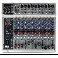
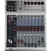
18, 26 and 34 Channel Stereo Mixing Consoles

Intended to alert the user to the presence of uninsulated "dangerous voltage" within the product's enclosure that may be of sufficient magnitude to constitute a risk of electric shock to persons.

Intended to alert the user of the presence of important operating and maintenance (servicing) instructions in the literature accompanying the product.
CAUTION: Risk of electrical shock - DO NOTOPEN!
CAUTION: To reduce the risk of electric shock, do not remove cover. No user serviceable parts inside. Refer servicing to qualified service personnel.
WARNING: To prevent electrical shock or fire hazard, do not expose this appliance to rain or moisture. Before using this appliance, read the operating guide for further warnings.

SRC® 4018 FC, 4026 FC and 4034 FC
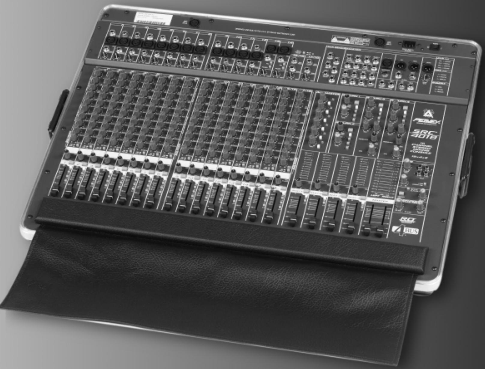
The SRC® 4026 FC, 4034 FC and 4018 FC are versatile four-bus consoles in 18, 26 and 34 channel versions, built into road-worthy cases. Designed for sound reinforcement applications, they can also be used in multitrack recording.
The standard channels feature discrete low-noise mic preamps with globally-switched 48V phantom power, low-cut filters, and four-band EQs. There are six auxiliary sends (four dedicated pre-EQ for monitor sends, two switchable pre-EQ/post-fader for monitor or effect sends), as well as bus assign (L/R, 1/2, 3/4), mute and PFL switches. The PFL logic automatically shifts the L/R meters to the PFL signal when any PFL button is pressed to assist in input gain adjustment and operates even when the channel is muted. The mute circuitry squelches all sends from the channel, including all auxiliary sends and bus sends.
Two "super" mic channels also have pad and polarity switches for those applications that require it, as well as the standard channel functions. There are no line inputs on these channels. In addition to the mic channels, there are two stereo (line level) channels for tape, CD or synth inputs. These have all the standard channel functions except low-cut filters. AUX 5 and AUX 6 on these channels are configured for stereo (AUX 5 is Left, AUX 6 is Right) and are pre-EQ/post-fader switchable.
There are four fully-assignable stereo returns with PFL and mute, two of which have treble and bass controls. They can be used for effect returns or for additional stereo inputs. A dual function headphone/control-room level control sets the volume of the headphones and the output level at the control room output jacks. RCA type stereo tape inputs and outputs are provided, with sends to the main L/R mix and the AUX 1 and 2 (monitor) mixes. A talkback mic input can be also be assigned to the main mix or to AUX 1-4 for announcements or stage communication.
All bus summing amps are designed with discrete transistor circuitry for low noise operation. A unique gain structure gives an additional 6 dB channel fader and summing amp headroom over other designs. The Left, Right, and four sub-mix master outputs each have LED meters. They are calibrated for a 0 dB reading at a +4 dBu output level. A balanced mono output (derived from the post fader Left and Right outputs) has its own level control. Each channel, stereo return, and master AUX send has an overload LED indicator that illuminates when the signal level is within 2 dB of clipping or when the PFL switch is activated. Electronic muting of the AUX and the Left and Right outputs greatly reduce any turn on and turn off transients.
Two lamp connectors are provided for Peavey ML™-2 or ML™-3 flexible lamps to illuminate the console in dark environments.
Channel Functions
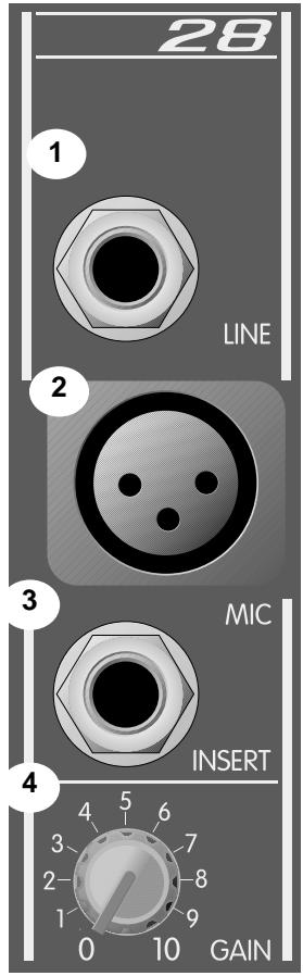
1. Line Input
1/4" balanced (TRS) high-impedance input for high-level signals. The tip is the positive input, which should also be used for unbalanced inputs. This input is connected through a 10 dB pad to the Mic Input (#2). The two inputs cannot be used simultaneously.
2. Mic Input
XLR balanced low-impedance channel input optimized for a microphone or other low-level source. Pin 2 is the positive input. Because of the wide range of gain adjustment, signal levels as high as +10 dBu (2.45 V RMS) can be accommodated. This connector has 48V on pins 2 and 3 (pin 1 is the ground reference) when the phantom power is enabled. (See note on #23.)
3. Insert
1/4" stereo (TRS) jack allows an external device to be inserted into the signal path before the EQ. The tip has the send signal, the ring is the return input. A switch in the jack normally connects the send to the return until a plug is inserted.
4. Gain
Varies the input gain to allow for a wide dynamic range. Proper adjustment of the input gain will maximize the signal-to-noise ratio. It should be set by depressing the PFL switch (#18) and adjusting for a 0 dB (+4 dBu) level at the L-R meters.
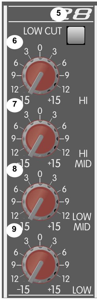
5. Low Cut
This is a low-cut filter with a corner frequency of 75Hz used to filter out rumble, wind noise, breath thumps, stage noise and other low-frequency components that rob power from the amplifiers and muddy the signal. The pre-EQ signals sent to the AUX sends are picked up after this switch so that the monitors can also benefit from this filter.
6. Hi EQ
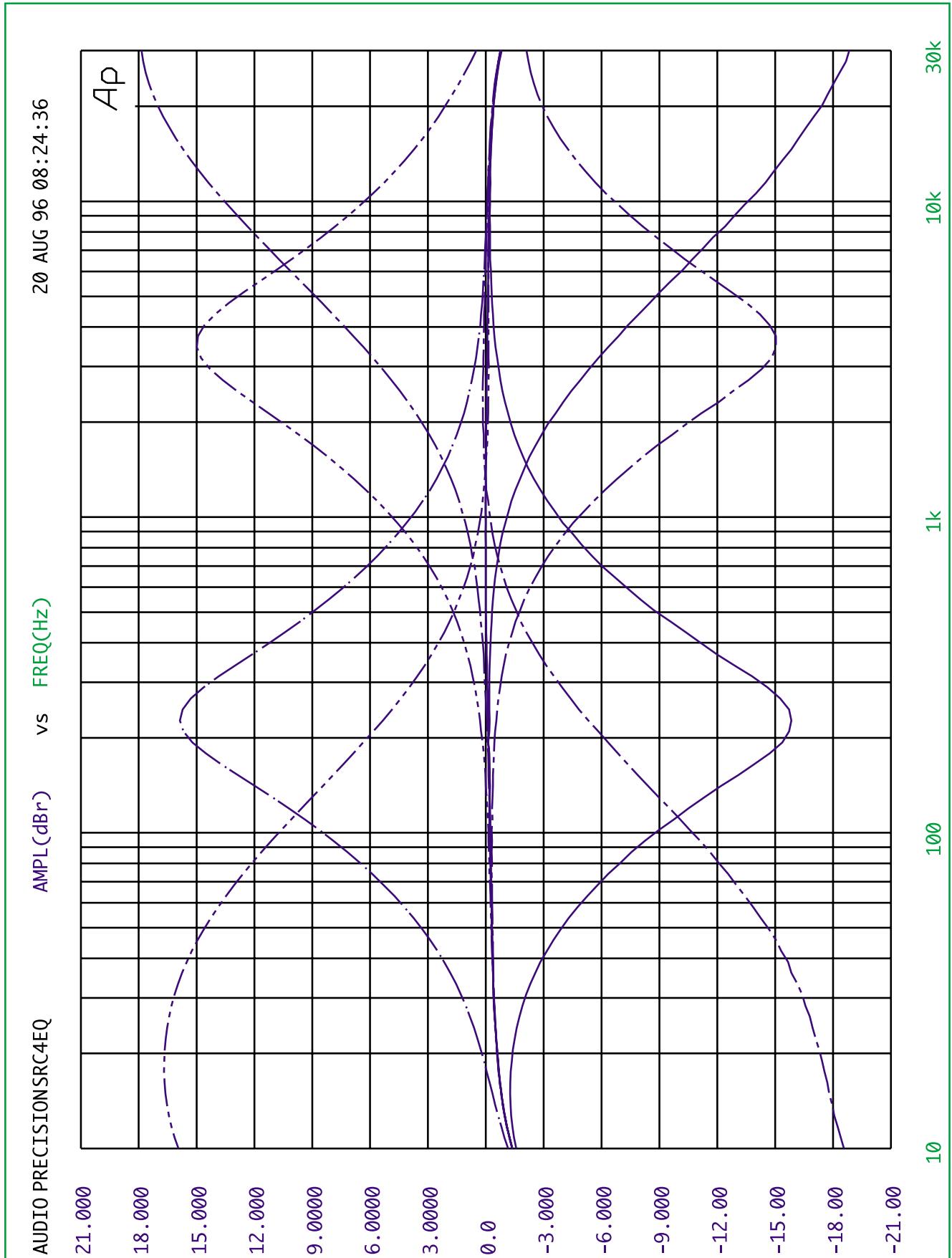
A shelving type of active tone control that varies the treble frequency levels ± 15 dB at 12kHz . It is designed to remove noise or to add brilliance to the signal, depending on the quality of the source.
7. Hi/Mid EQ
A bandpass (peak/notch) type of active tone control that varies the upper mid-range frequency levels ± 15 dB at 3.1kHz . This frequency is optimum for bringing out the clarity of a vocal mic without adding harshness or grit, or can reduce high frequency feedback.
8. Low/Mid EQ
A bandpass (peak/notch) type of active tone control that varies the lower mid-range frequency levels ± 15 dB at 250Hz . A slight cut in this frequency will usually help a mic that has a proximity effect to become more intelligible in close talking situations. It will also be useful to solve common feedback problems.
9. Low EQ
A shelving type of active tone control that varies the bass frequency levels ± 15 dB at 70Hz . It will add depth to thin signals or clean up muddy ones.
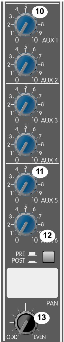
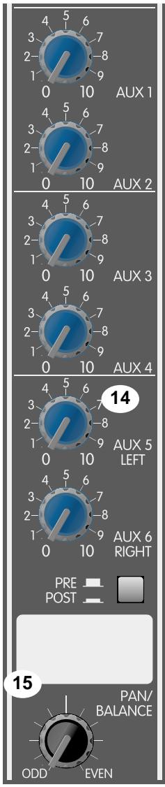
10. AUX 1/AUX 4
Adjusts the level of the channel signal (pre-EQ) that is added to the corresponding AUX mix. These are designed to be used for monitor sends.
11. AUX 5/AUX 6
Adjusts the level of the channel signal that is added to the corresponding AUX mix. These are selectable Pre- or Post-EQ Fader (#12) on all channels, and are configured in stereo (AUX 5=L, AUX 6=R) on the two stereo channels. They can be used as a stereo pair to drive stereo effect units. (See #14)
12. Pre/Post Fader
Establishes which signal will be present on the AUX 5 and AUX6 sends (#11). The out position picks up the signal after the low-cut filter, but before the four-band EQ. The depressed position picks up the signal after the Channel Fader (#20).
13. Pan
Sets the channel's position in one or more stereo fields determined by the selection of the Assignment Switches (#19).
14. Stereo Channel AUX Sends
AUX 1-AUX 4 sends are a mono mix of the left and right signals.
AUX 5 and AUX 6 are configured for stereo operation
(AUX 5 = L , AUX 6 = R ) on these channels.
15. Balance
Adjusts the balance of the stereo signal that is sent to the assignment select switches. Functions as a pan control for mono signals. (See #24)
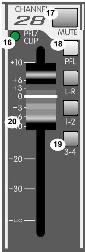
16. PFL/Clip LED
A dual-function LED that illuminates when the signal level is nearing the overload point, or if the PFL switch is engaged. This circuit monitors the input gain, EQ and post-fader stages for overload. It illuminates at +19 dBu and signals that gain or EQ boost should be reduced. (There is roughly 2 dB of headroom remaining when it lights.) When the PFL switch (#18) is depressed, it lights continuously to indicate that this channel has been assigned to the PFL mix.
17. Mute
Mutes the entire channel (all bus assignments and all AUX sends). The PFL signal is not affected, and can be used to adjust the channel's level while muted.
18. PFL
Connects the channel's pre-fader signal to the PFL mix and switches the headphone/control room source from the L-R mix to the PFL mix. It also connects the PFL signal to the L-R meters to aid in the setting the input gain (#4). The PFL/Clip LED (#16) will light when this switch is pressed to identify the PFL source.
19. Assignment Switches
Selects the channel's bus assignments (L-R, 1-2, 3-4) in pairs. The stereo position of the signal in the selected pair is determined by the Pan control (#13).
20. Channel Fader
Channel output level control. Sets the level sent to the Assign Switches (#19). The optimum setting for this control is the "0" (unity gain) position.
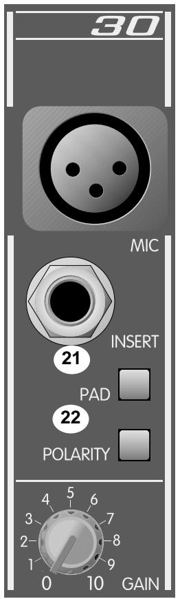
21. Pad
Attenuates the input signal by 10 dB. This will increase the dynamic range to accommodate a higher input level before clipping which may be necessary when close miking loud guitar amplifiers or drum kits.
22. Polarity
Reverses the polarity of the input signal. This will compensate for an out-of-phase input that would otherwise cause frequency cancellations in the mix. (Often needed for drum mics where both sides of the drum head are picked up in multiple microphone situations.)
23. Phantom power
Applies 48V DC voltage to all input XLR connectors to power microphones that require it. If phantom power is used, do not connect unbalanced dynamic microphones or other devices to the XLR inputs that cannot handle this voltage. (Some wireless receivers may be damaged, consult their manuals.) The Line Input jacks (#1) are not connected to the 48V supply, and are safe for all inputs (balanced or unbalanced). An unbalanced-to-balanced impedance converter such as the Peavey 5116 or 7201 (female XLR), or a Peavey 1:1 interface
adapter can also be used to isolate the mic input from 48V. Phantom power is not available at the talk back mic connector.
24. Stereo Input
High-impedance input for line-level signals. The left/mono input supplies signal to both the left and right inputs if there is nothing inserted to the right input jack.
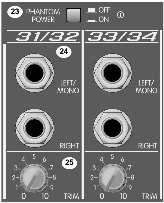
25. Trim
Varies the gain of the stereo input to optimize the signal-to-noise ratio.
The adjustment range is unity to +20 dB. Proper adjustment will maximize the signal-to-noise ratio, and can be set using the PFL switch. (See #4)
Master Functions
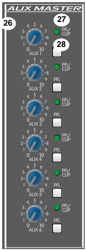
26. AUX Master Level
Sets the overall level of the AUX signal that is sent to the output jack. (See #49)
27. AUX PFL/Clip
A dual function LED that illuminates when the signal level is nearing the overload point, or if the PFL switch is engaged. It illuminates at +19 dBu. (There is roughly 2 dB of headroom remaining when it lights.) When the AUX PFL switch (#28) is depressed, it lights continuously to indicate that this AUX has been assigned to the PFL mix.
28. AUX PFL
Connects the AUX signal (pre-master level) to the PFL mix and switches the headache/control room source from the L-R mix to the PFL mix. It also connects the PFL signal to the L-R meters to aid in monitoring the output level.
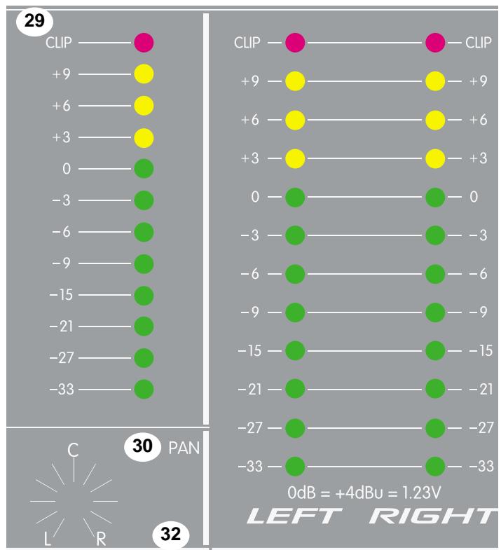
29. LED Meters
Six 12-segment LED arrays monitor the levels of the sub mixes and the main L-R outputs. The 0 dB reference level corresponds to +4 dBu. The L-R meter array is also used for PFL metering. (See #18, 28 and 33)
30. Sub Pan
Sets the position of the sub mix in the L-R stereo field.
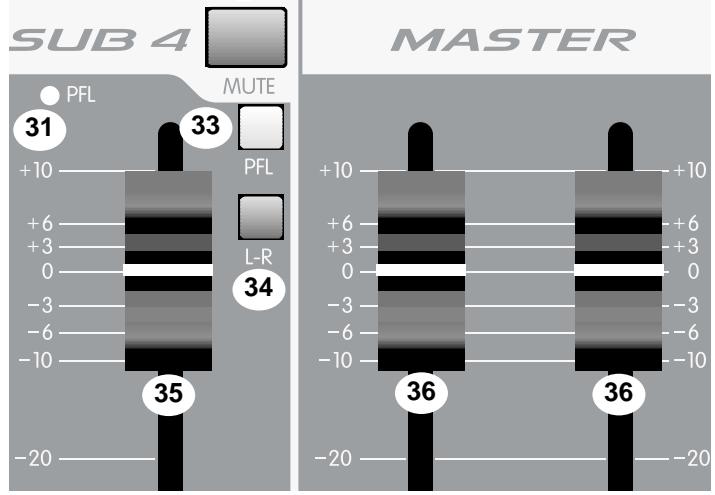
31. Sub PFL LED
Illuminates when the Sub PFL switch (#33) is depressed to indicate that this signal has been assigned to the PFL mix.
32. Sub Mute
Mutes the sub mix signal to the sub output and to the L-R mix. It does not affect the PFL signal, which can be used to check the levels when the sub mix is muted.
33. Sub PFL
Connects the sub signal (pre-master level) to the PFL mix and switches the headphone/control room source from the L-R mix to the PFL mix. It also connects the PFL mix signal to the L-R meters. (See #32.)
34. Sub L-R assign
Assigns the sub mix to the L-R mix with its stereo position determined by the Sub Pan control (#30).
35. Sub Fader
Sub mix output level control. Sets the level sent to the output jack and the L-R assign switch (#34). The optimum setting for this control is the "0" (unity gain) position.
36. Master Left and Right Faders
These are the main faders that set the level of the left and right mix (both balanced and unbalanced). The output levels are monitored by the left and right meters. The optimum setting for these controls is the "0" (unity gain) position.
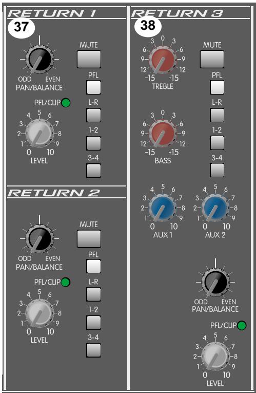
37. Stereo Returns 1 & 2
These are basic stereo input channels with level, pan, mute, PFL, and assignment switches. An LED that indicates both clipping and PFL is the same as that on the input channels. These inputs are line level and can be used for effect returns, tape inputs, or for slave mixer inputs.
38. Stereo Returns 3 & 4
Similar to the Stereo Returns 1 & 2, these two returns have treble and bass controls in addition to mono sends to the AUX 1 and AUX 2 mixes. These returns can be used as additional stereo input channels. (See #37.)
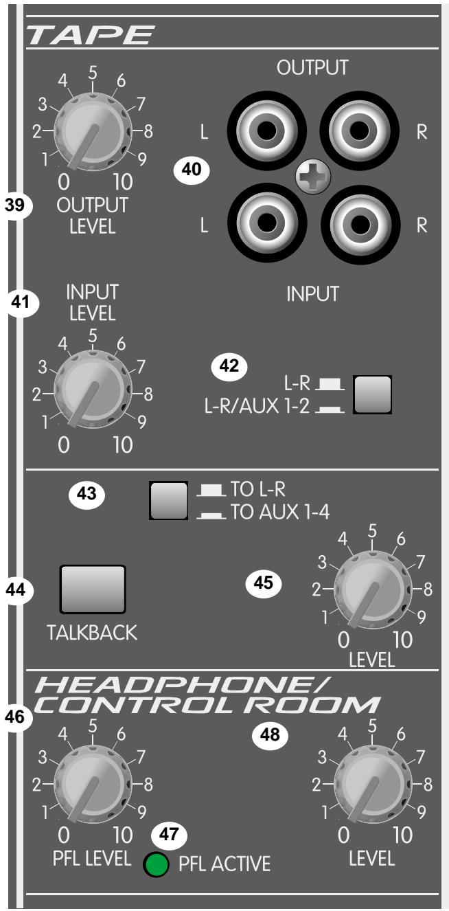
39. Tape Out Level
Sets the level of the main left and right stereo signal sent to the tape output jack. It is post master fader.
40. Tape Input/Output
One half of this stereo RCA phono jack provides a signal for the recording inputs of a stereo tape deck, with an amplitude set by the Tape Output Level control (#39). The other half accepts a stereo input (nominally -10 dBu) from the output of a tape deck or CD player.
Caution: The tape output signal includes the tape input signal, which can cause feedback if the Tape Input Level (#41) is turned up while recording on a single machine that is connected to both the tape output and tape input jacks.
41. Tape Input Level
Adjusts the level of the tape signal (#40) supplied to the L-R mix and to the AUX 1 & 2 buses.
42. Tape Assign
Adds a mono sum of the tape signal to the AUX 1 & 2 mixes. This can be used to send the tape signal to monitors for soundtrack monitoring. The tape signal is always assigned to the L-R mix, regardless of this switch's position.
43. Talkback Assign
Selects which outputs will have the talkback mic signal (L-R or AUX 1-4) for house or monitor feeds.
44. Talkback Enable
Press and hold to engage the talkback mic. The output is directed according to the assignment selection. (See #43.)
45. Talkback Level
Adjusts the level of the talkback mic. This affects the feed to the L-R and AUX 1-4.
46. PFL Master Level
Sets the level of the PFL mix that is sent to the headphone/control room level control. Functions only when PFL is active. (See #47.)
47. PFL Active
This LED illuminates when the PFL is active and its signal is overriding the standard L-R mix in the headphone and control room outputs and at the L-R meters. The signals that are present in the PFL mix can be seen by the individual LEDs lit.
48. Headphone/Control Room Level
Adjusts the volume of the headphone and control room outputs. The output changes from the L-R mix (post fader) to the PFL mix whenever the PFL is active.
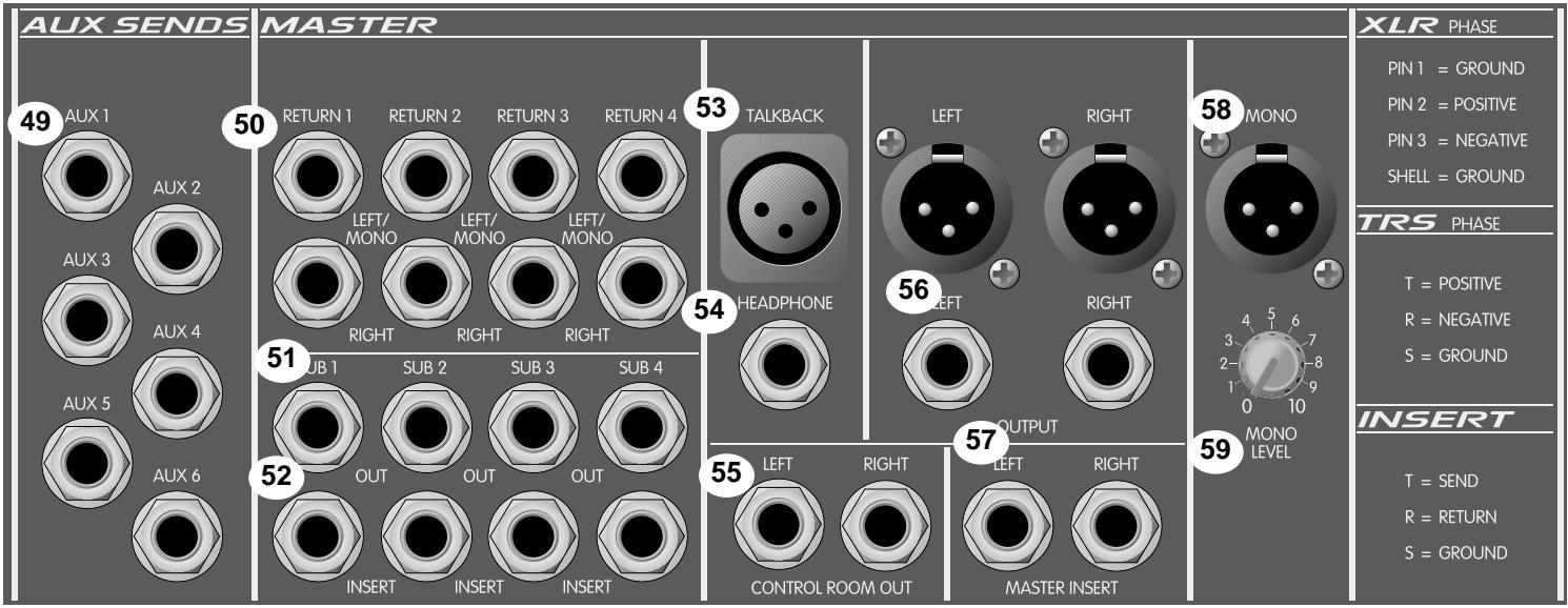
49. AUX Send
Output jack of the corresponding AUX mix. It is unbalanced, and can be used to feed an external monitor system or effect unit. The level is set by the AUX Master Level (#26) and the individual channel level control (see #10, 11).
50. Stereo Return
High impedance input for line level signals. The left/mono input supplies signal to both the left and right inputs if there is no input connected to the right input jack.
51. Sub Out
Output of the corresponding sub mix. It is unbalanced, with its output level set by the sub fader (#35).
52. Sub Insert
1/4" stereo (TRS) jack which allows an external device to be inserted into the signal path before the sub fader. The tip has the send signal, the ring is the return input. A switch in the jack normally connects the send to the return until a plug is inserted. The nominal level is -2 dBu.
53. Talkback Mic Input
Input connector for a low-impedance, balanced microphone used for house or stage communication. Pin 2 is the positive input. Phantom power is not available at this connector.
54. Headphone Output
This stereo jack (TRS) provides the signal to drive stereo headphones. It changes from the L-R mix to the PFL mix when the PFL is active. The level is set by the Headphone/Control Room Level Control (#48). Tip=Left, Ring=Right, Shield=Ground.
55. Control Room Output
1/4" left and right unbalanced outputs of the headphone mix to feed the control room monitor amps. The signal is exactly the same as that in the headphones.
56. Main Output
1/4" unbalanced and XLR balanced outputs of the Left and Right mixes. The level is set by the master left and right right faders (#36).
57. Main Insert
1/4" stereo (TRS) jack which allows an external device to be inserted into the signal path before the Master L/R Fader. The tip has the send signal, the ring is the return input. A switch in the jack normally connects the send to the return until a plug is inserted. The nominal level is -2 dBu.
58. Balanced Mono Output
An XLR balanced output of the mono mix. The level is set by the Mono Level control (#59). Pin 2 is the positive output.
59. Mono Level
Adjusts the level of the Balanced Mono Output (#58). The signal is a post fader sum of the left and right output signals. The center position is the unity gain setting; 7 dB of gain boost is available.
60. Power
The mixer's main power switch. The power on LED indicator will light when the unit is powered.
61. AC Mains Input
Connect the line cord to this connector to provide power to the unit. Damage to the equipment may result if improper line voltage is used. (See line voltage marking on unit.)
Line Cord
For your safety, we have incorporated a 3-wire line (mains) cable with proper grounding facilities. It is not advisable to remove the ground pin under any circumstances. If it is necessary to use the equipment without proper grounding facilities, suitable grounding adaptors should be used. Less noise and greatly reduced shock hazard exists when the unit is operated with the proper grounded receptacles.
62. Lamp Connector
Two XLR connectors are provided for low-voltage lamps (such as the Peavey ML™-2 or ML™-3) to illuminate the console in poorly lit environments. Each connector supplies 12V AC at 200ma between pins 1 and 2. The total maximum load should not exceed 400ma. These connectors are short-circuit protected, with automatic reset when a short is removed.
APPLICATIONS
The SRC® series of mixers were primarily designed for sound reinforcement applications, but are very capable recording mixers as well. Here are some typical methods of hook-up:
SOUND REINFORCEMENT:
- Microphones and other low impedance sources are connected to the XLR mic inputs; high level line inputs such as electronic musical instruments are connected to the line inputs. If problems arise because a microphone either picks up an out-of-phase signal (as when using multiple drum microphones), or a very loud signal causes clipping even at a minimum gain setting (as when close miking an amplifier or a drum head), it should be connected to a channel with pad and polarity switches. Stereo line level sources (synth, tape, CD, etc.) should be connected to one of the stereo channels, or to two of the mono line inputs (one panned left, the other panned right), or to a Return input that is not used for effects.
- The house power amplifier inputs should be connected to the main Left and Right outputs, or to the Mono output. The Mono output is a blend of the Left and Right output signals (post master fader) and has its own level control. It can be used to drive an additional amplifier that needs an independently set volume.
- Connect the monitor power amplifier input to the AUX 1, 2, 3 or 4 output. Four monitors are supported, with two additional available, if AUX 5 and 6 are also used for monitors (Pre) and not for effect sends (Post).
- If an effect device is used, connect its input to the AUX 5 or 6 output. These outputs can also be configured as a stereo pair (AUX 5 is the left, AUX 6 is the right) in the two stereo channels, and can be set up to feed a true stereo effects processor.
- The effect device outputs are connected to the Return 1, 2, 3 or 4 inputs.
- Connect a tape recorder to the Tape input and Tape output jacks. Care should be taken not to record on a deck that has its outputs connected to the tape input jacks and have the tape input level control turned up, or nasty feedback will result. If four-band equalization or a more specialized monitor send is needed, a stereo line channel can be used for tape input (see #1 and #24). Alternatively, a stereo return can be used for tape input. Both Return 3 and 4 have two-band EQ as well as monitor sends (to AUX 1 and 2) and full bus assignment capability.
APPLICATIONS (Cont.)
RECORDING:
The connections for recording are very similar to those of the sound reinforcement section above with the following differences:
- For recording tracks, connect the input sources as described above and use the sub mix sends to feed the recorder's inputs. For mixdown, the multitrack recorder's outputs are connected to the line inputs and assigned to the L/R mix.
- Connect the Sub outputs (the Left and Right outputs are included in this group if they are not in use) to the tape recorder inputs. The inserts can be used to patch compressors or EQ into the path. If effects are not being used, AUX 5 and 6 can also be used as sub mixes. If even more outputs are needed, the individual channel's insert jack can be used for a direct output. It is pre-EQ, pre-fader.
- Connect the Left and Right outputs to the two-track mixdown deck inputs. If a graphic EQ, compressor/limiter, or enhancer is used, connect it to the Left and Right Insert Jacks.
- The control room monitor amplifiers are connected to the Control Room Outputs. This is the same signal that is in the headphone output.
- Effect device inputs are connected to AUX 5 or 6 outputs. If a stereo send is required, use AUX 5 for left and AUX 6 for right.
- Effect device outputs are connected to Returns 1, 2, 3, 4 or any unused channel inputs (mono or stereo). If a channel input is used, make sure that the AUX send being used to feed the effects device is not turned up for that channel or it will output into its own input and awesome feedback will occur.
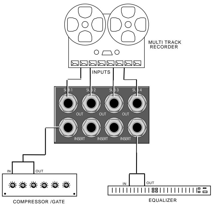
MULTI TRACK/SUB APPLICATION
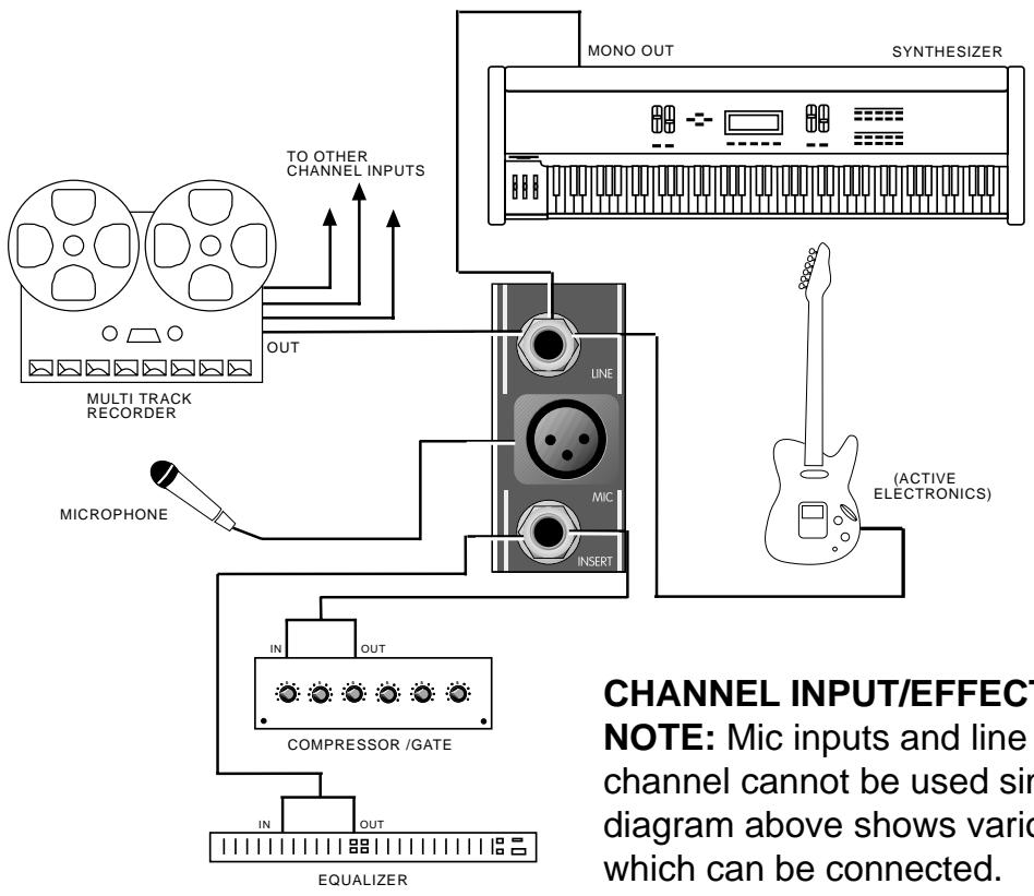
CHANNEL INPUT/EFFECTS APPLICATION
NOTE: Mic inputs and line inputs of the same channel cannot be used simultaneously. The diagram above shows various output devices which can be connected.
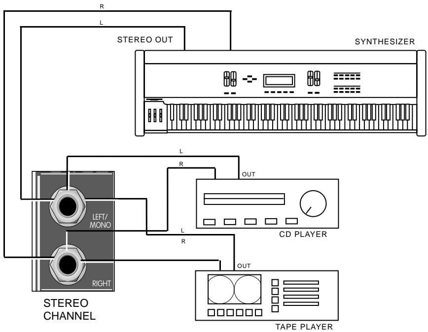
STEREO CHANNEL INPUT APPLICATION
SRC® 4018, 4026 and 4034 Sound Reinforcement Mixer Specifications:
Input Specifications:
| Function | Input Z (ohms) Min | Input Gain Setting | Input Levels | Balanced/ Unbalanced | Connector | ||
| Min** | Nominal* | Max | |||||
| Microphone (150 ohms) | 5K | Max gain (56 dB) Min gain (10 dB) | -72 dBu | -52 dBu | -34 dBu | Balanced | XLR Pin 1 Gnd, Pin 2 (+), Pin 3 (-) |
| -26 dBu | -6 dBu | +10 dBu | |||||
| Line (10K ohms) | 10K | Max gain (46 dB) Min gain (0 dB) | -62 dBu | -42 dBu | -24 dBu | Balanced | 1/4" TRS; Tip (+), Ring (-), Sleeve Ground |
| -16 dBu | +4 dBu | +20 dBu | |||||
| Insert Return | 22K | N/A (0 dB) | -16 dBu | +4 dBu | +20 dBu | Unbalanced | 1/4" TRS; Tip Send, Ring Return, Sleeve Ground |
| Stereo Line Input | 20K | Max gain (20 dB) Min gain (0 dB) | -36 dBu | -16 dBu | 0 dBu | Unbalanced | 1/4" Phono |
| -16 dBu | +4 dBu | +20 dBu | |||||
| Aux Return | 22K | N/A (0 dB) | -12 dBu | +4 dBu | +20 dBu | Unbalanced | 1/4" Phono |
| Tape | 10K | N/A (14 dB) | -26 dBu | -10 dBu | +6 dBu | Unbalanced | RCA Jacks |
0dBu = 0.775V (RMS)
* Min input level (Sensitivity) is the smallest signal that will produce nominal output (+4 dBu) with sub and master controls set for maximum gain.
Nominal settings are defined as all controls set at 0 dB (or 50% rotation for rotary pots) except the gain adjustment pot, which is as specified.
Output Specifications:
| Function | Minimum Load Z (ohms) | Output Levels | Balanced/ Unbalanced | Connector | |
| Nominal* Max | |||||
| Main L/R | 600 | +4 dBu | +20 dBu +26 dBu | Both | 1/4" Phono (Unbal), XLR Pin 1 Gnd, Pin 2 (+), Pin 3 (-) (Bal) |
| Mono | 600 | +4 dBu | +20 dBu | Balanced | XLR Pin 1 Gnd, Pin 2 (+), Pin 3 (-) |
| Sub Master | 600 | +4 dBu | +20 dBu | Unbalanced | 1/4" Phono |
| Aux Send | 600 | +4 dBu | +20 dBu | Unbalanced | 1/4" Phono |
| Channel Insert Send | 600 | +4 dBu | +20 dBu | Unbalanced | 1/4" TRS: Tip Send, Ring Return, Sleeve Ground |
| Sub Insert Send | 600 | +4 dBu | +20 dBu | Unbalanced | 1/4" TRS: Tip Send, Ring Return, Sleeve Ground |
| Control Room | 600 | +4 dBu | +20 dBu | Unbalanced | 1/4" Phono |
| Headphone | 8 | +4 dBu (no load) | +20 dBu | Unbalanced | 1/4" TRS: Tip Left, Ring Right, Sleeve Ground |
| Tape | 10K | -2 dBu | +20 dBu | Unbalanced | RCA Jack |
0dBu = 0.775V (RMS)
Gain:
| Mic Input Gain Adj Range: | 10 dB to 56 dB |
| Mic Input to Sub Output | 76 dB (Max Gain) |
| Mic Input to longest path | 93 dB (Max Gain) |
| Line Input Gain Adj Range: | 0 dB to 46 dB |
| Line Input to Sub Output | 66 dB (Max Gain) |
| Line Input to longest path | 83 dB (Max Gain) |
| Stereo Line Input Gain Adj Range | 0 dB to 20 dB |
| Stereo Line Input to Sub Output | 40 dB (Max Gain) |
| AUX Stereo Line Input longest path | 57 dB (Max Gain) |
| AUX Return to Sub Output | 16 dB (Max Gain) |
| AUX Return longest path | 33 dB (Max Gain) |
Frequency Response:
Mic Input to L-R Output 20 Hz to 30kHz +0 dB / -1 dB Stereo Input to L-R Output 20 Hz to 30k Hz +0 dB / -1 dB
Total Harmonic Distortion (THD):
<0.007% 20 Hz to 20 k Hz Mic to L-R output at Nominal Level (20 Hz to 80 kHz BW)
| Output | Residue Noise Ref: 0 dBu | S/N Ratio Ref: Nom output level | Test Conditions |
| Master L/R | -97 dBu | 101 dB | All Faders Down |
| -92 dBu | 96 dB | Master Fader Nominal, Channel Faders Down, All Channels Assigned | |
| Submaster | -97 dBu | 101 dB | All Faders Down |
| -92 dBu | 96 dB | Master Fader Nominal, Channel Faders Down, All Channels Assigned |
Hum and Noise Measurements: 22Hz to 22kHz BW
Equivalent Input Noise (EIN):
- 128 dBu (Input terminated with 150 ohms)
Crosstalk:
80 dB Adjacent Input Channels (20 Hz - 20kHz)
74 dB Left to Right Outputs (20 Hz - 20 kHz)
Common Mode Rejection Ratio (Mic Input):
50 dB min (20 Hz to 20 kHz)
70 dB typ @ 1 kHz
Meters:
L/R Master and all Submasters = 12 segment, peak reading.
(0dB = +4dBu)
Signal/Overload Indicators:
Red LED lights 2 dB below clipping.
Lamp Power :
12V AC @200ma per connector, or 12V AC @400ma total maximum load. Power is available between pins 1 and 2 and is electrically isolated from ground.
Power requirements:
DOM: 120V AC 60 Hz
50 watts nominal, 18 channel
EXP: 230V AC 50/60 Hz
55 watts nominal, 26 channel
60 watts nominal, 34 channel
50 watts nominal, 18 channel
55 watts nominal, 26 channel
60 watts nominal, 34 channel
| 1 | #0 | 1 | 13985 | 96-30-30 | 13985 |
| V # | XXXXXXXX | Q 120WBN | #20 | ||
| XXXXXXX | #Bm | XXXXXXX | 1.201046 | ||
| MIXED BY XOXY BZE MHWJ/20ZXH | |||||
| SQUEELE #EWS W#W#W#W#W#W#W#W#W#W#W#W#W#W#W#W#W#W#W#W#W#W#W#W#W#W#W#W#W#W#W#W#W#W#W#W#W#W#W#W#W#W#W#W#W#W#W#W#W#W#W# W#100 | 138351 | ||||
| #000 52700013373 A#M#d | |||||
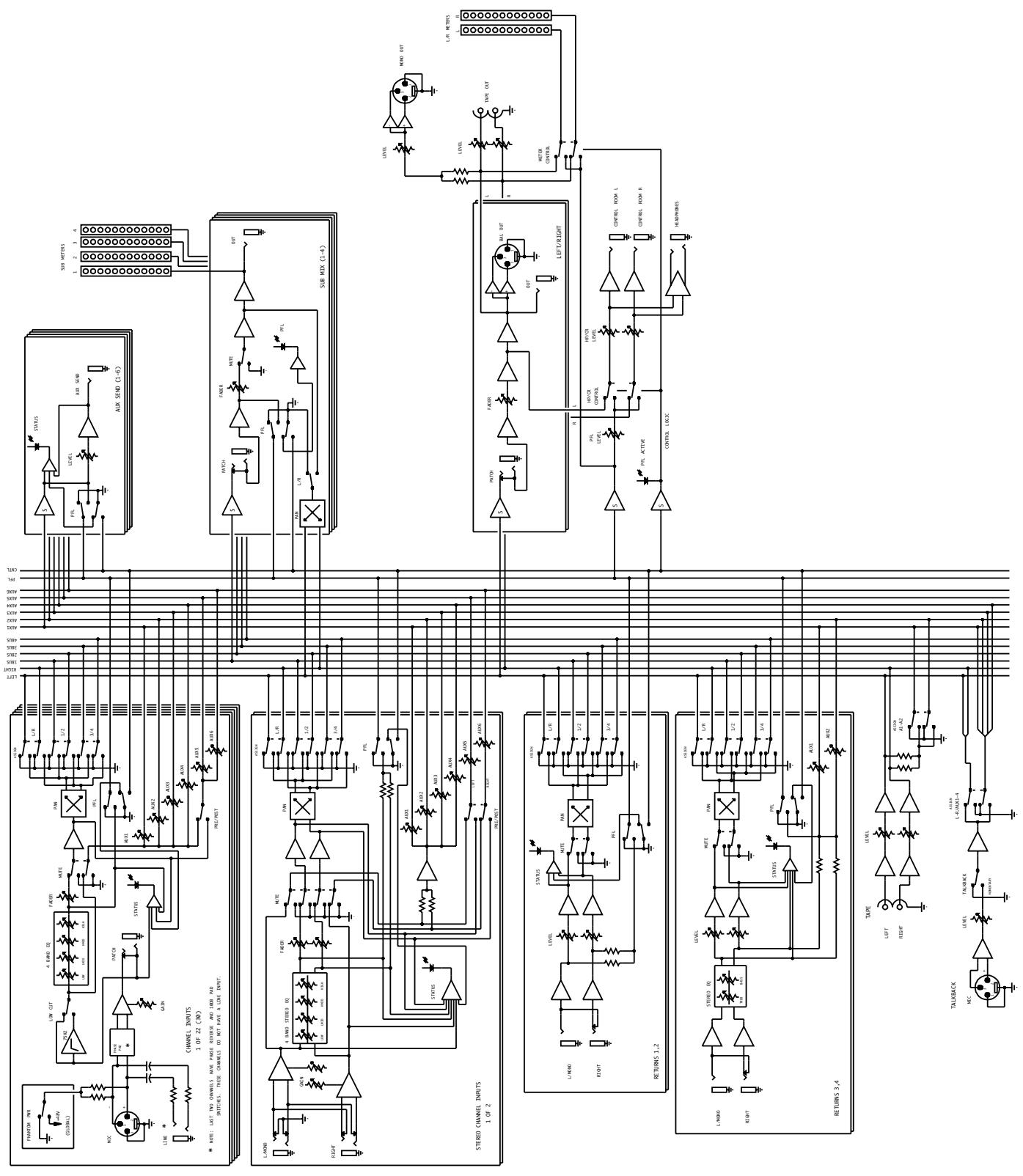
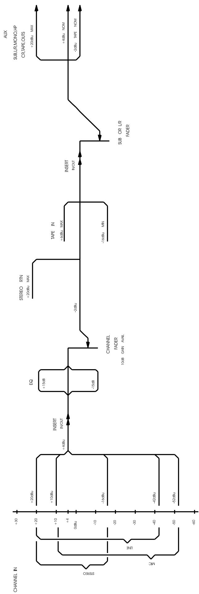
SRC® LEVELS Diagram
LEVELS
SPANISH
34. (Sub assignation G-D)
44. (Activation talkback)
For further information on other Peavey products, ask your Authorized Peavey Dealer for the appropriate

Guitars
Guitar Amplification
Bass Guitars
Bass Amplification
Sound Reinforcement Enclosures
Microphones
Keyboards
D J
Mixers, Powered/Non-Powered
Accessories/Cables
Effects Processors
Excess™ Wear
Monitor® Magazine
Key Issues
| NOTES: | |
THIS LIMITED WARRANTY VALID ONLY WHEN PURCHASED AND REGISTERED IN THE UNITED STATES OR CANADA. ALL EXPORTED PRODUCTS ARE SUBJECT TO WARRANTY AND SERVICES TO BE SPECIFIED AND PROVIDED BY THE AUTHORIZED DISTRIBUTOR FOR EACH COUNTRY.
PEAVEY ELECTRONICS CORPORATION ("PEAVEY") warrants this product, EXCEPT for covers, footswitches, patchcords, tubes and meters, to be free from defects in material and workmanship for a period of one (1) year from date of purchase, PROVIDED, however, that this limited warranty is extended only to the original retail purchaser and is subject to the conditions, exclusions, and limitations hereinafter set forth:
PEAVEY 90-DAY LIMITED WARRANTY ON TUBES AND METERS
If this product contains tubes or meters, Peavey warrants the tubes or meters contained in the product to be free from defects in material and workmanship for a period of ninety (90) days from date of purchase; PROVDED, however, that this limited warranty is extended only to the original retail purchaser and is also subject to the conditions, exclusions, and limitations hereinafter set forth.
CONDITIONS, EXCLUSIONS, AND LIMITATIONS OF LIMITED WARRANTYES
These limited warranties shall be void and of no effect, if:
a. The first purchase of the product is for the purpose of resale; or
b. The original retail purchase is not made from an AUTHORIZED PEAVEY DEALER; or
c. The product has been damaged by accident or unreasonable use, neglect, improper service or maintenance, or other causes not arising out of defects in material or workmanship; or
d. The serial number affixed to the product is altered, defaced, or removed.
In the event of a defect in material and/or workmanship covered by this limited warranty, Peavey will:
a. In the case of tubes or meters, replace the defective component without charge.;
b. In other covered cases (i.e., cases involving anything other than covers, footswitches, patchcords, tubes or meters), repair the defect in material or workmanship or replace the product, at Peavey's option; and provided, however, that, in any case, all costs of shipping, if necessary, are paid by you, the purchaser. THE WARRANTY REGISTRATION CARD SHOULD BE ACCURATELY COMPLETED AND MAILED TO AND RECEIVED BY PEAVEY WITHIN FOURTEEN (14) DAYS FROM THE DATE OF YOUR PURCHASE.
In order to obtain service under these warranties, you must:
a. Bring the defective item to any PEAVEY AUTHORIZED DEALER or AUTHORIZED PEAVEY SERVICE CENTER and present therewith the ORIGINAL PROOF OF PUR CHASE supplied to you by the AUTHORIZED PEAVEY DEALER in connection with your purchase from him of this product. If the DEALER or SERVICE CENTER is unable to provide the necessary warranty service you will be directed to the nearest other PEAVEY AUTHORIZED DEALER or AUTHORIZED PEAVEY SERVICE CENTER which can provide such service.
b. Ship the defective item, prepaid, to:
OR
PEAVEY ELECTRONICS CORPORATION
International Service Center
326 Hwy. 11 & 80 East
Meridian, MS 39301
including therewith a complete, detailed description of the problem, together with a legible copy of the original PROOF OF PURCHASE and a complete return address. Upon Peavey's receipt of these items: If the defect is remedial under these limited warranties and the other terms and conditions expressed herein have been complied with, Peavey will provide the necessary warranty service to repair or replace the product and will return it, FREIGHT COLLECT, to you, the purchaser.
Peavey's liability to the purchaser for damages from any cause whatsoever and regardless of the form of action, including negligence, is limited to the actual damages up to the greater of $500.00 or an amount equal to the purchase price of the product that caused the damage or that is the subject of or is directly related to the cause of action. Such purchase price will be that in effect for the specific product when the cause of action arose. This limitation of liability will not apply to claims for personal injury or damage to real property or tangible personal property allegedly caused by Peavey's negligence. Peavey does not assume liability for personal injury or property damage arising out of or caused by a non-Peavey alteration or attachment, nor does Peavey assume any responsibility for damage to interconnected non-Peavey equipment that may result from the normal functioning and maintenance of the Peavey equipment;
UNDER NO CIRCUMSTANCES WILL PEAVEY BE LIABLE FOR ANY LOST PROFITS, LOST SAVINGS, ANY INCIDENTAL DAMAGES, OR ANY CONSEQUENTIAL DAMAGES ASING OUT OF THE USE OR INABILITY TO USE THE PRODUCT, EVEN IF PEAVEY HAS BEEN ADVISED OF THE POSSIBILITY OF SUCH DAMAGES.
THESE LIMITED WARRANTY ARE IN LIEU OF ANY AND ALL WARRANTYES, EXPRESSED OR IMPLIED, INCLUDING, BUT NOT LIMITED TO, THE IMPLIED WARRANTY OF MERCHANTABILITY AND FITNESS FOR A PARTICULAR USE; PROVIDED, HOWEVER, THAT IF THE OTHER TERMS AND CONDITIONS NECESSARY TO THE EXISTENCE OF THE EXPRESSED, LIMITED WARRANTYES, AS HEREINABOVE STATED, HAVE BEEN COMPLIRED WITH, IMPLIED WARRANTYES ARE NOT DISCLAIMED DURING THE APPLICABLE ONE-YEAR OR NINETY-DAY PERIOD FROM DATE OF PURCHASE OF THIS PRODUCT.;
SOME STATES DO NOT ALLOW LIMITATION ON HOW LONG AN IMPLIED WARRANTY LASTS, OR THE EXCLUSION OR LIMITATION OF INCIDENTAL OR CONSEQUENTIAL DAMAGES, SO THE ABOVE LIMITATIONS OR EXCLUSIONS MAY NOT APPLY TO YOU. THESE LIMITED WARRANTYES GIVE YOU SPECIFIC LEGAL RIGHTS, AND YOU MAY ALSO HAVE OTHER RIGHTS WHICH MAY VARY FROM STATE TO STATE.;
THESE LIMITED WARRANTY ARE THE ONLY EXPRESSED WARRANTYES ON THIS PRODUCT, AND NO OTHER STATEMENT, REPRESENTATION, WARRANTY, OR AGREEMENT BY ANY PERSON SHALL BE VALID OR BINDING UPON PEAVEY.;
In the event of any modification or disclaimer of expressed or implied warranties, or any limitation of remedies, contained herein conflicts with applicable law, then such modification, disclaimer or limitation, as the case may be, shall be deemed to be modified to the extent necessary to comply with such law;
Your remedies for breach of these warranties are limited to those remedies provided herein and Peavey Electronics Corporation gives this limited warranty only with respect to equipment purchased in the United States of America
INSTRUCTIONS — WARRANTY REGISTRATION CARD
- Mail the completed WARRANTY REGISTRATION CARD to:
PEAVEY ELECTRONICS CORPORATION
P.O. BOX 2898
Meridian, MS 39302-2898
a. Keep the PROOF OF PURCHASE. In the event warranty service is required during the warranty period, you will need this document. There will be no identification card issued by Peavey Electronics Corporation;
- IMPORTANCE OF WARRANTY REGISTRATION CARDS AND NOTIFICATION OF CHANGES OF ADDRESSES::
a. Completion and mailing of WARRANTY REGISTRATION CARDS — Should notification become necessary for any condition that may require correction, the REGISTRATION CARD will help ensure that you are contacted and properly notified.;
b. Notice of address changes - If you move from the address shown on the WARRANTY REGISTRATION CARD, you should notify Peavey of the change of address so as to facilitate your receipt of any bulletins or other forms of notification which may become necessary in connection with any condition that may require dissemination of information or correction.
- You may contact Peavey directly by telephoning (601) 483-5365.
IMPORTANT SAFETY INSTRUCTIONS
WARNING: When using electric products, basic cautions should always be followed, including the following:
- Read all safety and operating instructions before using this product.
- All safety and operating instructions should be retained for future reference.
- Obey all cautions in the operating instructions and on the back of the unit.
- All operating instructions should be followed.
- This product should not be used near water, i.e., a bathtub, sink, swimming pool, wet basement, etc.
- This product should be located so that its position does not interfere with its proper ventilation. It should not be placed flat against a wall or placed in a built-in enclosure that will impede the flow of cooling air.
- This product should not be placed near a source of heat such as a stove, radiator, or another heat producing amplifier.
- Connect only to a power supply of the type marked on the unit adjacent to the power supply cord.
- Never break off the ground pin on the power supply cord. For more information on grounding, write for our free booklet "Shock Hazard and Grounding."
- Power supply cords should always be handled carefully. Never walk or place equipment on power supply cords. Periodically check cords for cuts or signs of stress, especially at the plug and the point where the cord exits the unit.
- The power supply cord should be unplugged when the unit is to be unused for long periods of time.
- If this product is to be mounted in an equipment rack, rear support should be provided.
- Metal parts can be cleaned with a damp rag. The vinyl covering used on some units can be cleaned with a damp rag or an ammonia-based household cleaner if necessary. Disconnect unit from power supply before cleaning.
- Care should be taken so that objects do not fall and liquids are not spilled into the unit through the ventilation holes or any other openings.
- This unit should be checked by a qualified service technician if:
a. The power supply cord or plug has been damaged.
b. Anything has fallen or been spilled into the unit.
c. The unit does not operate correctly.
d. The unit has been dropped or the enclosure damaged.
- The user should not attempt to service this equipment. All service work should be done by a qualified service technician.
- This product should be used only with a cart or stand that is recommended by Peavey Electronics.
- Exposure to extremely high noise levels may cause a permanent hearing loss. Individuals vary considerably in susceptibility to noise induced hearing loss, but nearly everyone will lose some hearing if exposed to sufficiently intense noise for a sufficient time.
The U.S. Government's Occupational Safety and Health Administration (OSHA) has specified the following permissible noise level exposures.
| Duration Per Day In Hours | Sound Level dBA, Slow Response |
| 8 | 90 |
| 6 | 92 |
| 4 | 95 |
| 3 | 97 |
| 2 | 100 |
| 1 1/2 | 102 |
| 1 | 105 |
| 1/2 | 110 |
| 1/4 or less | 115 |
According to OSHA, any exposure in excess of the above permissible limits could result in some hearing loss. Ear plugs or protectors in the ear canals or over the ears must be worn when operating this amplification system in order to prevent a permanent hearing loss if exposure is in excess of the limits as set forth above. To ensure against potentially dangerous exposure to high sound pressure levels, it is recommended that all persons exposed to equipment capable of producing high sound pressure levels such as this amplification system be protected by hearing protectors while this unit is in operation.
SAVE THESE INSTRUCTIONS!

PEAVEY®
Features and specifications subject to change without notice.
Peavey Electronics Corporation 711 A Street / Meridian, MS 39301 / U.S.A. / (601) 483-5365 / Fax 486-1278

80304427
- SRC® 4018 FC, 4026 FC AND 4034 FC
- CHANNEL FUNCTIONS
- LINE INPUT
- MIC INPUT
- INSERT
- GAIN
- LOW CUT
- HI EQ
- HI/MID EQ
- LOW/MID EQ
- LOW EQ
- AUX 1/AUX 4
- AUX 5/AUX 6
- PRE/POST FADER
- PAN
- STEREO CHANNEL AUX SENDS
- BALANCE
- PFL/CLIP LED
- MUTE
- PFL
- ASSIGNMENT SWITCHES
- CHANNEL FADER
- PAD
- POLARITY
- PHANTOM POWER
- STEREO INPUT
- TRIM
- MASTER FUNCTIONS
- AUX MASTER LEVEL
- AUX PFL/CLIP
- AUX PFL
- LED METERS
- SUB PAN
- SUB PFL LED
- SUB MUTE
- SUB PFL
- SUB L-R ASSIGN
- SUB FADER
- MASTER LEFT AND RIGHT FADERS
- STEREO RETURNS 1 & 2
- STEREO RETURNS 3 & 4
- TAPE OUT LEVEL
- TAPE INPUT/OUTPUT
- TAPE INPUT LEVEL
- TAPE ASSIGN
- TALKBACK ASSIGN
- TALKBACK ENABLE
- TALKBACK LEVEL
- PFL MASTER LEVEL
- PFL ACTIVE
- HEADPHONE/CONTROL ROOM LEVEL
- AUX SEND
- STEREO RETURN
- SUB OUT
- SUB INSERT
- TALKBACK MIC INPUT
- HEADPHONE OUTPUT
- CONTROL ROOM OUTPUT
- MAIN OUTPUT
- MAIN INSERT
- BALANCED MONO OUTPUT
- MONO LEVEL
- POWER
- AC MAINS INPUT
- LINE CORD
- LAMP CONNECTOR
- APPLICATIONS
- SOUND REINFORCEMENT
- APPLICATIONS (CONT.)
- RECORDING
- CHANNEL INPUT/EFFECTS APPLICATION
- SRC® 4018, 4026 AND 4034 SOUND REINFORCEMENT MIXER SPECIFICATIONS
- INPUT SPECIFICATIONS
- FREQUENCY RESPONSE
- TOTAL HARMONIC DISTORTION (THD)
- EQUIVALENT INPUT NOISE (EIN)
- CROSSTALK
- COMMON MODE REJECTION RATIO (MIC INPUT)
- METERS
- SIGNAL/OVERLOAD INDICATORS
- LAMP POWER
- POWER REQUIREMENTS
- SPANISH
- (SUB ASSIGNATION G-D)
- (ACTIVATION TALKBACK)
- PEAVEY 90-DAY LIMITED WARRANTY ON TUBES AND METERS
- CONDITIONS, EXCLUSIONS, AND LIMITATIONS OF LIMITED WARRANTYES
- OR
- PEAVEY ELECTRONICS CORPORATION
- INSTRUCTIONS — WARRANTY REGISTRATION CARD
- IMPORTANT SAFETY INSTRUCTIONS
- SAVE THESE INSTRUCTIONS
Brand : PEAVEY
Model : SRC 4034 FC
Category : Audio Mixer