
PV 10 USB - Audio Mixer PEAVEY - Free user manual and instructions
Find the device manual for free PV 10 USB PEAVEY in PDF.

| Product type | Compact audio mixing console |
| Brand | Peavey |
| Model | PV 10 USB |
| Microphone inputs | 6 balanced XLR inputs with 48V phantom power |
| Line inputs | 2 stereo 6.35 mm jack inputs (impedance 10 kΩ) |
| Additional inputs | RCA inputs (Tape In) and USB port |
| Main outputs | 2 balanced 6.35 mm jack outputs (L/R, max level +22 dBu) |
| Monitor output | 1 balanced 6.35 mm jack output (MON Send) |
| Headphone output | 6.35 mm TRS jack with level control |
| Effect processor | 16 digital presets (reverbs, delays, doubler, etc.) |
| Channel equalization | 3-band (high, mid, low) with +/-15 dB |
| Low-cut filter | 80 Hz on each microphone input |
| Power supply | Internal, mains with ground (100-240 VAC) |
| Phantom power | 48V switchable via switch (indicator LED) |
| USB connectivity | USB port for recording/playback (compatible with Windows XP/7/8 and Mac OS X 10.0+) |
| Dimensions (W x D x H) | 30.80 x 37.47 x 8.89 cm |
| Rack mounting | Optional kit available |
| Cleaning | Use a dry cloth only |
| Safety | Do not open the device, refer repairs to a qualified technician |
| Hearing protection | Respect sound levels to avoid irreversible hearing damage |
Frequently Asked Questions - PV 10 USB PEAVEY
User questions about PV 10 USB PEAVEY
0 question about this device. Answer the ones you know or ask your own.
Ask a new question about this device
Download the instructions for your Audio Mixer in PDF format for free! Find your manual PV 10 USB - PEAVEY and take your electronic device back in hand. On this page are published all the documents necessary for the use of your device. PV 10 USB by PEAVEY.
USER MANUAL PV 10 USB PEAVEY
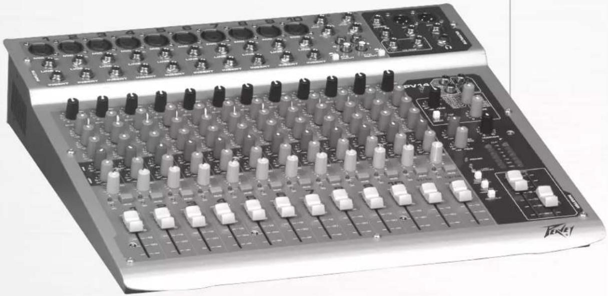
PV ® 10 • PV ® 14 • PV ® 20
Compact Mixer
Operating Manual
natural_image
Black and white photo of a Benel audio workstation with multiple knobs and control knobs (no visible text or labels)


Intended to alert the user to the presence of uninsulated “dangerous voltage” within the product’s enclosure that may be of sufficient magnitude to constitute a risk of electric shock to persons.
Intended to alert the user of the presence of important operating and maintenance (servicing) instructions in the literature accompanying the product.
CAUTION: Risk of electrical shock — DO NOT OPEN!
CAUTION: To reduce the risk of electric shock, do not remove cover. No user serviceable parts inside. Refer servicing to qualified service personnel.
WARNING: To prevent electrical shock or fire hazard, this apparatus should not be exposed to rain or moisture, and objects filled with liquids, such as vases, should not be placed on this apparatus. Before using this apparatus, read the operating guide for further warnings.
Protective earthing terminal. The apparatus should be connected to a mains socket outlet with a protective earthing connection.


IMPORTANT SAFETY INSTRUCTIONS
WARNING: When using electrical products, basic cautions should always be followed, including the following:
- Read these instructions.
- Keep these instructions.
- Heed all warnings.
- Follow all instructions.
- Do not use this apparatus near water.
-
Clean only with a dry cloth.
-
Do not block any of the ventilation openings. Install in accordance with manufacturer's instructions.
-
Do not install near any heat sources such as radiators, heat registers, stoves or other apparatus (including amplifiers) that produce heat.
- Do not defeat the safety purpose of the polarized or grounding-type plug. A polarized plug has two blades with one wider than the other. A grounding type plug has two blades and a third grounding plug. The wide blade or third prong is provided for your safety. If the provided plug does not fit into your outlet, consult an electrician for replacement of the obsolete outlet.
-
Protect the power cord from being walked on or pinched, particularly at plugs, convenience receptacles, and the point they exit from the apparatus.
-
Only use attachments/accessories provided by the manufacturer.
-
Use only with a cart, stand, tripod, bracket, or table specified by the manufacturer, or sold with the apparatus. When a cart is used, use caution when moving the cart/apparatus combination to avoid injury from tip-over.
-
Unplug this apparatus during lightning storms or when unused for long periods of time.
-
Refer all servicing to qualified service personnel. Servicing is required when the apparatus has been damaged in any way, such as power-supply cord or plug is damaged, liquid has been spilled or objects have fallen into the apparatus, the apparatus has been exposed to rain or moisture, does not operate normally, or has been dropped.
-
Never break off the ground pin. Write for our free booklet "Shock Hazard and Grounding." Connect only to a power supply of the type marked on the unit adjacent to the power supply cord.
-
If this product is to be mounted in an equipment rack, rear support should be provided.
-
Note for UK only: If the colors of the wires in the mains lead of this unit do not correspond with the terminals in your plug, proceed as follows: a) The wire that is colored green and yellow must be connected to the terminal that is marked by the letter E, the earth symbol, colored green or colored green and yellow. b) The wire that is colored blue must be connected to the terminal that is marked with the letter N or the color black. c) The wire that is colored brown must be connected to the terminal that is marked with the letter L or the color red.
-
This electrical apparatus should not be exposed to dripping or splashing and care should be taken not to place objects containing liquids, such as vases, upon the apparatus.
-
The on/off switch in this unit does not break both sides of the primary mains. Hazardous energy can be present inside the chassis when the on/off switch is in the off position. The mains plug or appliance coupler is used as the disconnect device, the disconnect device shall remain readily operable.
-
Exposure to extremely high noise levels may cause a permanent hearing loss. Individuals vary considerably in susceptibility to noise-induced hearing loss, but nearly everyone will lose some hearing if exposed to sufficiently intense noise for a sufficient time. The U.S. Government's Occupational Safety and Health Administration (OSHA) has specified the following permissible noise level exposures:
Duration Per Day In Hours Sound Level dBA, Slow Response
| 8 90 | |
| 6 92 | |
| 4 95 | |
| 3 97 | |
| 2 100 | |
| 1 1/2 102 | |
| 1 105 | |
| 1/2 | 110 |
| 1/4 or less | |
According to OSHA, any exposure in excess of the above permissible limits could result in some hearing loss. Earplugs or protectors to the ear canals or over the ears must be worn when operating this amplification system in order to prevent a permanent hearing loss, if exposure is in excess of the limits as set forth above. To ensure against potentially dangerous exposure to high sound pressure levels, it is recommended that all persons exposed to equipment capable of producing high sound pressure levels such as this amplification system be protected by hearing protectors while this unit is in operation.
SAVE THESE INSTRUCTIONS!
a) The wire that is colored green and yellow must be connected to the terminal that is marked by the letter E, the earth symbol, colored green or colored green and yellow.
b) The wire that is colored blue must be connected to the terminal that is marked with the letter N or the color black.
c) The wire that is colored brown must be connected to the terminal that is marked with the letter L or the color red.
Logo referenced in Directive 2002/96/EC Annex IV(OJ(L)37/38,13.02.03 and defined in EN 50419: 2005
The bar is the symbol for marking of new waste and is applied only to equipment manufactured after 13 August 2005
Correct Disposal of this product. This marking indicates that this product should not be disposed with other house hold wastes throughout the EU. To prevent possible harm to the environment or human health from uncontrolled waste disposal, recycle it responsibly to promote the sustainable reuse of material resources. To return your used device, please use the return and collection systems, or contact the retailer where the product was purchased. They can take this product for environmental safe recycling.

Features and specifications are subject to change without notice.
Peavey Electronics Corporation • 711 A Street • Meridian, MS 39301
(601) 483-5365 • FAX (601) 486-1278 • www.peavey.com
ENGLISH
PV ® 10, PV ® 14 and PV ® 20
Compact Mixers
Congratulations on purchasing the Peavey PV ® 10, PV ® 14, or the PV ® 20 Compact Mixer. The PV 10, PV 14, and PV 20 are studio-quality mixing consoles designed to meet diverse needs while occupying a small space. These are the perfect consoles for small venue performances or home recording environments. PV series mixers feature built-in DSP effects that are useful in real-world recording and sound reinforcement, while parameter controls allow you to tailor each effect to meet your needs.
Please read this guide carefully to ensure your personal safety as well as the safety of your equipment.
FEATURES:
- Six XLR mic inputs on PV 10, ten XLR mic inputs on PV 14, and sixteen XLR mic inputs on the PV 20
- Two stereo channels with RCA and 1/4" inputs
- Three-band channel EQ
• A/B stereo input selector reduces patching - Inserts on all mono channels
- 80 Hz low-cut switch on all mic inputs
- USB connectivity (standard on the PV 20, optional on both PV10 & PV 14)
- Clip LEDs monitor the entire signal path for clipping
• Signal LEDs on every input channel - Mute switches with LED indicator on every input channel
• 48 Volt phantom power switch
• Effects send on every channel with stereo return - Internal digital effects with 16 selections, including reverb, delay and vocal enhancement
- Effect parameter adjustment allows you to customize each effect selection
• Monitor send on every channel
• Zero latency record monitoring capabilities
• Control room output with level control - Contour EQ switch
- Internal universal input power supply
- Optional rack-mount kit (PV 10 and PV 14 Only)

Installation Note:
This unit must have the following clearances from any combustible surface: top: 8", sides: 12", back: 12"
Gain
This control establishes the nominal operating level for the channel. The input gain can be adjusted over a wide range to compensate for soft voices or very loud drums. To maximize the signal-to-noise ratio, the gain should be set to the proper level, with the channel Fader (12) set to o. If the clip LED comes on and remains lit, try reducing the gain.
② 80 Hz Low Cut
The low cut filter has a corner frequency of 80 Hz. When engaged, it can improve clarity by removing low frequencies that make a mix sound muddy. This feature is especially useful when playing outside on a windy day or on a hollow-sounding, noisy stage. These kinds of ambient noises can rob your sound system of power. Engaging this switch will remove those frequencies from the system and restore power where needed.
3 Hi EQ
This active tone control (shelving type: ±15 dB) varies the level of the high frequency range.
4 Mid EQ
This active tone control (peak dip: ±15 dB) varies the level of the mid frequency range.
5 Low EQ
This active tone control (shelving type: ±15 dB) varies the level of the low frequency range.
Caution: Excessive low frequency boost causes greater power consumption and increases the possibility of speaker damage.
6 MON Send (MON Send 2 on the PV®20 only)
This control adjusts the level of the channel signal sent to the monitor output. The signal is taken before the channel Fader (12) but after the channel EQ.
⑦ EFX Send
This control adjusts the level of the channel signal added to the effects mix. The effects send signal is taken after the channel Fader (12) so that adjustments made to the fader will also affect the send level.
8 Pan
This knob controls the placement of the signal in the stereo field. When rotated completely counterclockwise, the signal is present only on the left channel; when rotated completely clockwise, only in the right channel. This control functions as a balance control to adjust the relative level of the left and right signals on stereo channels 5/6 and 7/8 on the PV 10 (11/12 and 13/14 on the PV 14, 17/18 and 19/20 on the PV 20).
9 Mute
The mute button is a quick way to remove the channel signal from the left/right main mix, as well as effects and monitor sends, without disturbing the control settings.
10 Clip/Mute LED
This light normally indicates that the channel signal level is nearing the overload point, but it also lights when mute is engaged. The clip indicator circuit monitors the signal at many points in the channel to ensure that it catches all instances of clipping. It illuminates at +19 dBu and warns that the gain or EQ boost should be reduced. When it lights, roughly 3 dB of headroom remains.
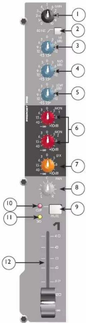

Signal LED
The signal LED lights when the channel level reaches approximately -20 dBu. This not only indicates which channels are active, but also serves as a mini level meter.

Fader
The channel Fader is the channel output control, which sets the signal level to the left and right mix and the effects send control. The optimum setting is the o (unity gain) position.

Tape In/Out
The tape input jacks are designed to accommodate tape, CD, or computer sound card output levels. The output level is +4 dBu for connecting to a recorder or sound card input. The tape inputs can be used as an additional stereo input by engaging
the Tape/USB to Main Mix switch (27). The tape input can also be used to monitor the recorder/sound card output without the risk of feedback.
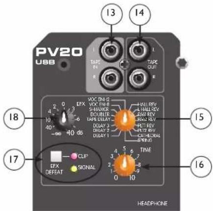
NOTE: The USB input is routed to the Tape Input left/right. If another device is connected to the Tape Input, this signal will be combined with the USB input signal.

EFX Select
This rotary switch selects one of sixteen available effects. As shown in the table below.
| Effect | Description Application Parameter | |||
| 1 Hall | Rev Medium Concert Hall | Ensemble Rev Time | ||
| 2 Large | Hall Rev Larger Concert Hall | Darker Gen Reverb | Rev Time | |
| 3 Room 1 Rev | Intimate Room Bright | Pop Vocal Rev Time | ||
| 4 Room 2 Rev | Larger Room Darker Drums, Rhythm | Rev Time | ||
| 5 Plate 1 Rev | Bright | Pop Vocal Rev Time | ||
| 6 Plate 2 Rev | Darker | Drums | Rev Time | |
| 7 | Cathedral | Large Space, Long and Darker | Choir | Rev Time |
| 8 Spring | Classic Spring | Guitar | Rev Time | |
| 9 | Delay 1 | Single Delay (Slap-back) | Voc/Inst | Dly Time |
| 10 | Delay 2 | Warm Delay with Repeats | Instruments | Dly Time |
| 11 | Delay 3 | Dark Delay with Repeats | Instruments | Dly Time |
| 12 | Tape Delay | Warm Delay | Instruments | Dly Time/Feedback |
| 13 | Doubler | Single Delay, 30-120 ms | Instruments | Dly Time |
| 14 | Shimmer | Warm Delay with Modulation | Instruments | Dly Time |
| 15 | Vocal Enhancement 1 | Brightens and Adds Room Reverb | Vocals | Rev Level |
| 16 | Vocal Enhancement 2 | Brightens and Adds Spring Reverb | Vocals | Rev Level |
16 EFX Time
This control adjusts the time of the particular reverb or delay.
17 Green Signal LED and Red Clip LED
The green Signal LED and red Clip LED are used to set the operating input level to the PV 10, PV 14, and PV 20 effects processors. The signal level to the processor is affected by channel Fader, the Effects Send and the Effects Send Master Controls. Start with the Master Control (20) set to o (12 o'clock) and adjust the channel sends so that the signal LED lights and the clip LED blinks on occasionally, if at all. The clip LED lights 6 dB below clipping. Pressing the EFX defeat mutes the effects signal and lights the clip/mute LED.
18 EFX Return
EFX Return
Once the input level is set (see 17) use the EFX Return control to mix the effects processor output into the main left/right outputs. Remember, a little reverb goes a long way.
19 MON Send Master
This is the master output level control for the monitor mix. The output level sent to the Monitor Send jack (37) is controlled by the channel Monitor Send controls (6) and by this master control.
20 EFX Send Master
This is the master output level control for the EFX mix. The output level sent to the EFX Send jack and the internal effects processor is controlled by the channel Fader (12), the channel EFX Send controls (7), and by this master control. The o position is the recommended setting for this control.
21 Headphone Level
This knob sets the headphone and control room output levels. To avoid damage to your hearing, make sure to turn the dial fully counterclockwise before using headphones. Slowly turn the knob clockwise until you reach a comfortable listening level. Normally, the signal in the headphones is the left/right signal. If the Tape to Control Room (26) is engaged, the tape signal is also included.
22 LED Meters
Two eight-segment LED arrays are provided to monitor the levels of the main left/right outputs. These meters range
from -30 dB to +19 dB. The o dB position on the meter corresponds to +4 dBu at the outputs.
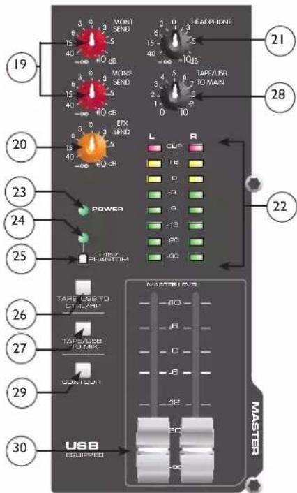
23 Power LED
This LED indicates AC power is supplied to the unit, the power switch is on, and the unit is functioning properly.
24 Phantom Power LED
This LED lights when the Phantom Power Switch (25) has been engaged.
Front Panel

25 Phantom Power Switch
This Switch applies +48 VDC voltage to the input XLR connectors to power microphones requiring phantom power.
If phantom power is used, do not connect unbalanced dynamic microphones or other devices to the XLR inputs.
26 Tape To CTRL/HP
Depressing this switch adds the tape return to the Control Room (39) and Headphone Outputs (41) for zero latency monitoring.
27 Tape/to Mix (Tape/USB to Mix)
Depressing this switch routes the signal from the Tape Inputs (13) or USB Input (44) to the Left/Right Outputs (40). The USB input level is controlled by the computer volume control.
28 Tape/USB to Main (PV®20 only)
This knob provides a convenient way to adjust the Tape Input (13) or USB Input (44) volume. (On models PV 10 and PV 14, adjust the USB Input (44) volume with the computer volume control.)
29 Contour Switch
Engaging this switch enhances the signal by adding both bass and treble frequencies. This is especially effective at lower volumes or for tape/CD playback.
30 Master Level Faders
These Master Faders control the levels sent to the main left/right outputs. Best results are obtained when these controls are set near the o point.
Rear Panel
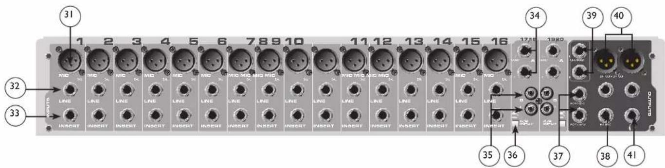
XLR balanced inputs are optimized for a microphone or other low impedance source. Pin 2 is the positive input. Because of the wide range of gain adjustment, signal levels up to +14 dBu can be accommodated.
32 Line (1/4") Inputs
Line inputs provide 1/4" balanced (TRS) 10 k Ohm impedance input. The tip is the positive input and should be used for unbalanced inputs. It has 20 dB less gain than the XLR input and does not have phantom power available. The Mic and Line inputs should not be used simultaneously.
33 Insert
The 1/4" TRS connectors allow external signal processors to be inserted into the channel signal path. Tip=Send; Ring=Return; Sleeve=Ground.
34 Stereo (1/4") Inputs
These 1/4" unbalanced inputs work as a stereo line input using both jacks or as a mono input if the connection is made to the left/mono input only. The A/B input selector must be in the "A" position for these jacks to be active.
35 RCA Inputs
These RCA inputs work as stereo line inputs. The A/B input selector must be in the “B” position for these jacks to be active.
36 A/B Switch
The A/B input selector switch expands the capability of the PV ircledR 10, PV ircledR 14, and the PV ircledR 20 mixers by allowing two stereo sources to be connected to each stereo line input. Instead of repatching, the switch selects which input jacks are active.
37 MON Send
The MON Send features a 1/4" TRS Z-balanced jack in the master section. This output can be used with the Tip, Ring, Sleeve (TRS) balanced or Tip, Sleeve (TS) unbalanced connectors. The MON mix is determined by the amount of signal being sent to the MON bus in each channel and by the Monitor Master control (19).
38 EFX Send
The EFX Send features a 1/4" TRS Z-balanced jack in the master section. These outputs can be used with Tip, Ring, Sleeve (TRS) balanced, or Tip, Sleeve (TS) unbalanced connectors. The EFX mix is determined by the amount of signal being sent to the EFX bus in each channel and by the EFX master control.
39 Control Room Outputs
The Control Room outputs feature two 1/4" TRS Z-balanced jacks. These outputs can be used with Tip, Ring, Sleeve (TRS) balanced, or Tip, Sleeve (TS) unbalanced connectors. The Control Room output level is adjusted with the Headphone level control (21).
40 Left/Right Outputs
The left/right Outputs feature two 1/4" TRS Z-balanced jacks and two fully balanced XLR outputs. The 1/4" outputs can be used with Tip, Ring, Sleeve (TRS) balanced or Tip, Sleeve (TS) unbalanced connectors. The output level is set by the Master Level Faders (30). Both outputs can be used simultaneously.
41 Headphone Output
The Headphone Output is a 1/4" TRS (Tip= Left; Ring = Right; Sleeve = Ground). The signal sent to this output is normally the left/right mix. When the Tape to Control Room switch is engaged, the tape input signal is added to the left/right mix and can be monitored in the headphones.
Rear Panel
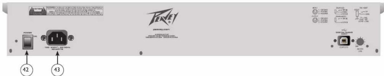
42 Power Switch
Depressing the power switch supplies power to the unit.
Warning: The power switch in this unit breaks only one side of the line. Hazardous energy may be present inside the mixer when the power switch is in the OFF position.
43 Removable Power Cord
This receptacle is for the IEC line cord (included) that provides AC power to the unit. Connect the line cord to this connector and to a properly grounded AC supply. Damage to the equipment may occur if an improper line voltage is used (see voltage marking on unit). Never remove or cut the ground pin of the line cord plug. The console is supplied with a properly rated line cord. If lost or damaged, replace this cord with one of the proper rating.
NOTE FOR UK ONLY:
If the colors of the wires in the mains lead of this unit do not correspond with the colored markings identifying terminals in your plug, proceed as follows: (1) The wire that is colored green and yellow must be connected to the terminal marked by the letter E, or by the earth symbol, or colored green or green and yellow. (2) The wire that is colored blue must be connected to the terminal that is marked with the letter N, or colored black. (3) The wire that is colored brown must be connected to the terminal that is marked with the letter L or colored red.
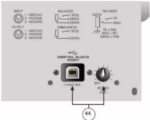
44 USB port and USB Record Level Control
The USB port is used to connect the PV ® Series USB mixer to a computer for recording or playing back digital audio to/from your computer. The USB port sends the mixer's main/tape stereo out to the computer. The amount of the main mix signal being sent to the USB port can be adjusted using the Record Level control located next to the USB port. The USB port receives digital audio from the computer; it can then be assigned through the “Tape/USB to Mix” switch (27) to the main left/right output. The USB input level is controlled by the computer volume control.
Compatible with Windows XP, Windows 7 and Windows 8. Also compatible with Mac OS X 10.0 or later.
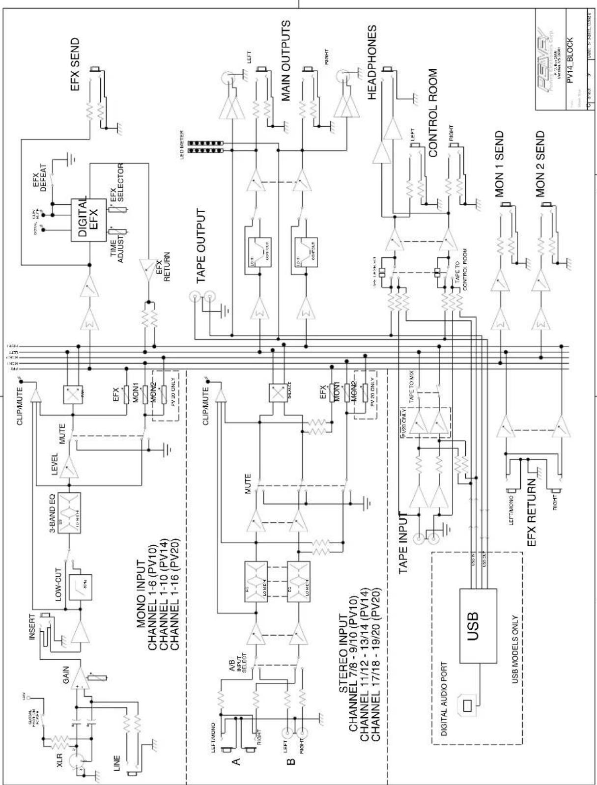
Block Diagram-PV ® 10, PV ® 14 & PV ® 20
flowchart
graph TD
    subgraph MONO_INPUT
        A["LINE"] --> B["GAIN"]
        B --> C["INSERT"]
        C --> D["LOW-CUT"]
        D --> E["3-BAND EQ"]
        E --> F["LEVEL MUTE"]
        F --> G["CLIP/MUTE"]
        G --> H["Digital EFX"]
        H --> I["EFX DEFEAT"]
        I --> J["EFX SELECTOR"]
        J --> K["EFX RETURN"]
    end

    subgraph STEREO_INPUT
        L["A"] --> M["A/B INPUT SELECT"]
        M --> N["MUTE"]
        N --> O["BLADE"]
        O --> P["TAPE OUTPUT"]
        P --> Q["LED METER"]
        Q --> R["LEFT"]
        R --> S["MAIN OUTPUTS"]
        S --> T["RIGHT"]
        T --> U["HEADPHONES"]
        U --> V["TAPE INPUT"]
        V --> W["TAPE TO MIX"]
        W --> X["TAPE TO CONTROL ROOM"]
        X --> Y["CONTROL ROOM"]
        Y --> Z["LEFT"]
        Z --> AA["MINIMUM OUTPUT"]
        AA --> AB["MINIMUM OUTPUT"]
        AB --> AC["MINIMUM OUTPUT"]
        AC --> AD["MINIMUM OUTPUT"]
        AD --> AE["MINIMUM OUTPUT"]
        AE --> AF["MINIMUM OUTPUT"]
        AF --> AG["MINIMUM OUTPUT"]
        AG --> AH["MINIMUM OUTPUT"]
        AH --> AI["MINIMUM OUTPUT"]
        AI --> AJ["MINIMUM OUTPUT"]
        AJ --> AK["MINIMUM OUTPUT"]
        AK --> AL["MINIMUM OUTPUT"]
        AL --> AM["MINIMUM OUTPUT"]
        AM --> AN["MINIMUM OUTPUT"]
        AN --> AO["MINIMUM OUTPUT"]
        AO --> AP["MINIMUM OUTPUT"]
        AP --> AQ["MINIMUM OUTPUT"]
        AQ --> AR["MINIMUM OUTPUT"]
        AR --> AS["MINIMUM OUTPUT"]
    end

    subgraph ESTER
        AT["USB MODELS ONLY"] --> AU["USB"]
        AU --> AV["USB MODELS ONLY"]
        AV --> AW["USB MODELS ONLY"]
        AW --> AX["USB MODELS ONLY"]
        AX --> AY["USB MODELS ONLY"]
        AY --> AZ["USB MODELS ONLY"]
        AZ --> BA["USB MODELS ONLY"]
        BA --> BB["USB MODELS ONLY"]
        BB --> BC["USB MODELS ONLY"]
        BC --> BD["USB MODELS ONLY"]
        BD --> BE["USB MODELS ONLY"]
        BE --> BF["USB MODELS ONLY"]
        BF --> BG["USB MODELS ONLY"]
        BG --> BH["USB MODELS ONLY"]
    end

    subgraph MONO_INPUT
        BI["XLR"] --> BJ["GOLDAL PROOFUM SWITCH"]
        BJ --> BK["LUX/IN"]
        BK --> BL["GAIN"]
        BL --> BM["INSERT"]
        BM --> BN["Low-CUT"]
        BN --> BO["3-BAND EQ 10-20Ω"]
        BO --> BP["MUTE"]
        BP --> BQ["PV 20 ONLY"]
    end

    subgraph STEREO_INPUT
        BOA["A"] --> BQ
        BQ --> BN
        BN --> BO
        BO --> BP
    end

    subgraph MONO_INPUT
        BOB["A"] --> BN
        BN --> BO
        BO --> BP
    end

    subgraph ESTER
        BOC["A"] --> BN
        BN --> BO
        BO --> BP
    end

    subgraph MONO_INPUT
        BOF["A"] --> BN
        BN --> BO
        BO --> BP
    end

    subgraph STEREO_INPUT
        BOG["A"] --> BN
        BN --> BO
        BO --> BP
    end

    subgraph MONO_INPUT
        BOH["A"] --> BN
        BN --> BO
        BO --> BP
    end

    subgraph ESTER
        BOI["A"] --> BN
        BN --> BO
        BO --> BP
    end

    subgraph MONO_INPUT
        BOJ["A"] --> BN
        BN --> BO
        BO --> BP
    end

    subgraph ESTER
        BOK["A"] --> BN
        BN --> BO
        BO --> BP
    end

    subgraph MONO_INPUT
        BQ["A"] --> BN
        BN --> BO
        BO --> BP
    end

    subgraph ESTER
        BQ
        BQ
    end
PV ® 10, PV ® 14 & PV ® 20 Series Specifications
Inputs
| Function Input Z(ohms min) | Input Gain Setting Min** Nominal* Max | Bal/Unbal | Connector | ||||
| Microphone(150 ohms) | 2.2k Max Gain(60 dB) | -76 dBu | -56 dBu | -38 dBu | Bal XLR Pin 1 GndPin 2 (+)Pin 3 (-) | ||
| Min Gain(10 dB) | -24 dBu | -4 dBu | +14 dBu | ||||
| Line(10 k ohms) | 10k Max Gain(40 dB) | -56 dBu | -36 dBu | -18 dBu | Bal 1/4" | TRS;Tip (+)Ring (-)Sleeve Ground | |
| Min Gain(-10 dB) | -10 dBu | +14 dBu | +32 dBu | ||||
| Stereo LineInput | 10k Max Gain(20 dB)Nominal | -36 dBu | -16 dBu | +2 dBu | Unbal 1/4" | TS;Tip (+)Sleeve Ground | |
| -21 dBu | -1 dBu | +17 dBu | |||||
| Tape 10k N/A | -17 dBu -10 dBV +12 dBu Unbal RCA Phono | ||||||
o dBu=0.775 V (RMS)
** Min Input Level (sensitivity) is the smallest signal that will produce nominal output (+4 dBu) with channel and master faders set for maximum gain.
* Nominal settings are defined as all controls set at 0 dB (or 50% rotation for rotary pots) except the gain adjustment pot which is as specified.
Outputs
| Function | Min Load Z (ohms) | Output Levels | Bal/ Unbal | Connector | |
| Nominal | Max | ||||
| Main Left/Right | 600 | +4 dBu | +22 dBu | Bal | XLR Pin Ground TipPin 2 (+), Pin 3 (-) 1/4" TRS: Tip (+), Ring (-)Sleeve Ground |
| Effects and Monitor Sends | 600 | +4 dBu | +22 dBu | Bal | 1/4" TRS: Tip (+), Ring (-)Sleeve Ground |
| Control Room | 600 | +4 dBu | +22 dBu | Bal | 1/4" TRS: Tip (+), Ring (-)Sleeve Ground |
| Headphone | 8 | +4 dBu (no load) | +22 dBu | Unbal | 1/4" TRS; Tip Left, Ring RightSleeve Ground |
| Tape | 2.2k | +4 dBu | +22 dBu | Unbal | RCA Phono |
| USBo dBu=0.775 V (RMS) | |||||
Gain
| Mic Input Gain Adjustment Range: | 10 dB to 60 dB |
| Mic Input to Left/Right Balance Output | 88 dB (max gain) |
| Line Input Gain Adjustment Range: | -10 dB to 40 dB |
| Line Input to Left/Right Balance Output | 60 dB (max gain) |
| Stereo Line Input Gain Adjustment Range: | Off to +20 dB |
| Stereo Line Input to Left/Right Output | 40 dB (max gain) |
PV ® 10, PV ® 14, & PV ® 20 Specifications
Frequency Response
Mic Input to Left/Right Output 14 Hz to 25 kHz +0 dB/-1 dB
Total Harmonic Distortion
| <0.02% 20 Hz to 20 kHz Mic to Left/Right Output (10 Hz to 80 kHz BW) | |
| <0.005% Typical (22 Hz to 22 kHz BW) | |
| <0.0007% Mic Pre-amp Distortion | |
Hum and Noise
| Output | Residual Noise | S/N Ratio (Ref: +4dBu) | Test Conditions |
| Master Left/Right | 97 dBu-90 dBu-83 dBu | 101 dB94 dB87 dB | Master Fader Down, Channel Levels DownMaster Fader Nominal, Channel Levels DownMaster Fade Nominal, Channel Faders Nominal,Panned Odd Channels (left), Even Channels (right) |
| Monitor Send -95 dBu-80 dBu | 99 dB84 dB | All controls offAll channel sends nominal, masters nominal | |
| Effects Sends -100 dBu-80 dBu | 104 dB84 dB | All controls offAll channel sends nominal, masters nominal | |
| (Hum and noise measurements: 22 Hz to 22 kHz BW) | |||
Equivalent Input Noise (EIN)
-129 dBu (input terminated with 150 ohms)
Crosstalk/Attenuation
| Adjacent Input Channels (1 kHz) >90 dB | Mute Button Attenuation (1 kHz) >90 dB |
| Left to Right Outputs (1 kHz) >75 dB | Channel Fader Kill (1 kHz) >85 dB |
Common Mode Rejection Ratio (Mic Input)
| 50 dB minimum (20 Hz to 20 kHz) | |
| 70 dB typical @ 1 kHz |
Meters
8 segment, peak reading (o db = +4 dBu)
Signal/Overload Indicators
Red LED lights 3 dB below clipping
Dimensions
| PV10: 12.125" wide x 14.75" deep x 3.5" high(30.80cm x 37.47cm x 8.89cm) | PV20: 22.125" wide x 15.75" deep 3.5" high(56.2cm x 40.0cm x 8.9xm) |
| PV14: 16.125" wide x 14.75" deep x 3.5" high(40.96cm x 37.47cm x 8.89cm) |

Installation Note:
This unit must have the following clearances from any combustible surface: top: 8", sides: 12", back: 12"
Weight
PV10: 9.3 lbs. (4.22 kg)
PV14: 12.1 lbs (5.49kg)
PV20: 16.3 lbs. (7.39kg)
Power Requirements
PV10: 100-240 VAC 50/60 Hz 15 Watts
PV14: 100-240 VAC 50/60 Hz 17 Watts
PV20: 100-240 VAC 50/60 Hz 30 Watts
ESPAÑOL
PV ® 10, PV ® 14 and PV ® 20
Compact Mixers
Descripción
flowchart
graph TD
    subgraph MONO_INPUT
        A["LINE"] --> B["GAIN"]
        B --> C["INSERT"]
        C --> D["LOW-CUT"]
        D --> E["3-BAND EQ"]
        E --> F["LEVEL MUTE"]
        F --> G["CLIP/MUTE"]
        G --> H["Digital EFX"]
        H --> I["EFX DEFEAT"]
        I --> J["EFX SELECT"]
        J --> K["EFX SEND"]
    end

    subgraph STEREO_INPUT
        L["A"] --> M["A/B INPUT SELECT"]
        M --> N["MUTE"]
        N --> O["BALANCE"]
        O --> P["TAPE OUTPUT"]
        P --> Q["LFD METER"]
        Q --> R["LEFT MAIN OUTPUTS"]
        R --> S["RIGHT HEADPHONES"]
        T["B"] --> U["BANK"]
        U --> V["MUTE"]
        V --> W["BALANCE"]
        W --> X["COMP CUB"]
        X --> Y["CONTROL ROOM"]
        Y --> Z["TAPE INPUT"]
        Z --> AA["TAFE TO MIX"]
        AA --> AB["TAPE TO CONTROL ROOM"]
        AB --> AC["MON 1 SEND"]
        AC --> AD["MON 2 SEND"]
    end

    subgraph USB
        AE["USB MODELS ONLY"] --> AF["UPP B"]
        AF --> AG["UPP CUB"]
        AG --> AH["LEFT/MON"]
        AH --> AI["EFX RETURN"]
        AI --> AJ["RIGHT"]
    end

    subgraph TAPE OUTPUT
        AK["LEAF OUTPUT"] --> AL["MINIMUM OUTPUT"]
        AL --> AM["MINIMUM OUTPUT"]
        AM --> AN["MINIMUM OUTPUT"]
        AN --> AO["TAPE OUTPUT"]
        AP["MAIN OUTPUTS"] --> AQ["MAIN OUTPUTS"]
        AQ --> AR["TAPE OUTPUT"]
        AS["HEADPHONES"] --> AT["TAPE OUTPUT"]
        AU["CONTROL ROOM"] --> AV["TAPE OUTPUT"]
        AW["MINIMUM OUTPUT"] --> AX["TAPE OUTPUT"]
        AY["TAPE OUTPUT"] --> AZ["TAPE OUTPUT"]
    end

    subgraph MON 1 SEND
        BA["MON 1 SEND"] --> BB["TAPE OUTPUT"]
        BC["MON 2 SEND"] --> BD["TAPE OUTPUT"]
    end

    subgraph MON 2 SEND
        BE["MON 2 SEND"] --> BF["TAPE OUTPUT"]
        BG["TAPE OUTPUT"] --> BH["TAPE OUTPUT"]
        BI["TAPE OUTPUT"] --> BJ["TAPE OUTPUT"]
    end

    subgraph MON 100
        BK["MON 100"] --> BL["TAPE OUTPUT"]
        BM["MON 100"] --> BN["TAPE OUTPUT"]
        BO["MON 100"] --> BP["TAPE OUTPUT"]
    end

    subgraph MON 160
        BOB["MON 160"] --> BPB["TAPE OUTPUT"]
        BPB --> BPBOUT
        BPB --> BPBOUT
    end

    subgraph MON 140
        BPB2["TAPE OUTPUT"] --> BPBOUT
    end

    subgraph MON 120
        BPB3["TAPE OUTPUT"] --> BPBOUT
    end

    subgraph MON 180
        BPB4["TAPE OUTPUT"] --> BPBOUT
    end

    subgraph MON 160
        BPB5["TAPE OUTPUT"] --> BPBOUT
    end

    subgraph MON 140
        BPB6["TAPE OUTPUT"] --> BPBOUT
    end

    subgraph MON 120
        BPB7["TAPE OUTPUT"] --> BPBOUT
    end

    subgraph MON 180
        BPB8["TAPE OUTPUT"] --> BPBOUT
    end

    subgraph MON 160
        BPB9["TAPE OUTPUT"] --> BPBOUT
    end

    subgraph MON 140
        BPB10["TAPE OUTPUT"] --> BPBOUT
    end

    subgraph MON 120
        BPB11["TAPE OUTPUT"] --> BPBOUT
    end

    subgraph MON 180
        BPB12["TAPE OUTPUT"] --> BPBOUT
    end

    subgraph MON 160
        BPB13["TAPE OUTPUT"] --> BPBOUT
    end

    subgraph MON 140
        BPB14["TAPE OUTPUT"] --> BPBOUT
    end

    subgraph MON 120
        BPB15["TAPE OUTPUT"] --> BPBOUT
    end

    subgraph MON 180
        BPB16["TAPE OUTPUT"] --> BPBOUT
    end

    subgraph MON 160
        BPB17["TAPE OUTPUT"] --> BPBOUT
    end

    subgraph MON 140
        BPB18["TAPE OUTPUT"] --> BPBOUT
    end

    subgraph MON 120
        BPB19["TAPE OUTPUT"] --> BPBOUT
    end

    subgraph MON 180
        BPB20["TAPE OUTPUT"] --> BPBOUT
    end

    subgraph MON 160
        BPB21["TAPE OUTPUT"] --> BPBOUT
    end

    subgraph MON 140
        BPB22["TAPE OUTPUT"] --> BPBOUT
    end

    subgraph MON 120
        BPB23["TAPE OUTPUT"] --> BPBOUT
    end

    subgraph MON 180
        BPB24["TAPE OUTPUT"] --> BPBOUT
    end

    subgraph MON 160
        BPB25["TAPE OUTPUT"] --> BPBOUT
    end

    subgraph MON 140
        MPD["MINIMUM OUTPUT"] --> MPDOUT
    end

    subgraph MON 120
        MPD2["TAPE OUTPUT"] --> MPD2OUT
    end

    subgraph MON 180
        MPD3["TAPE OUTPUT"] --> MPD3OUT
    end

    subgraph MON 160
        MPD4["TAPE OUTPUT"] --> MPD4OUT
    end

    subgraph MON 140
        MPD5["TAPE OUTPUT"] --> MPD5OUT
    end

    subgraph MON 120
        MPD6["TAPE OUTPUT"] --> MPD6OUT
    end

    subgraph MON 180
        MPD7["TAPE OUTPUT"] --> MPD7OUT
    end

    subgraph MON 160
        MPD8["TAPE OUTPUT"] --> MPD8OUT
    end

    subgraph MON 140
        MPD9["TAPE OUTPUT"] --> MPD9OUT
    end

    subgraph MON 120
        MPD10["TAPE OUTPUT"] --> MPD10OUT
    end

    subgraph MON 180
        MPD11["TAPE OUTPUT"] --> MPD11OUT
    end

    subgraph MON 160
        MPD12["TAPE OUTPUT"] --> MPD12OUT
    end

    subgraph MON 140
        MPD13["TAPE OUTPUT"] --> MPD13OUT
    end

    subgraph MON 120
        MPD14["TAPE OUTPUT"] --> MPD14OUT
    end

    subgraph MON 180
        MPD15["TAPE OUTPUT"] --> MPD15OUT
    end

    subgraph MON 160
        MPD16["TAPE OUTPUT"] --> MPD16OUT
    end

    subgraph MON 140
        MPD17["TAPE OUTPUT"] --> MPD17OUT
    end

    subgraph MON 120
        MPD18["TAPE OUTPUT"] --> MPD18OUT
    end

    subgraph MON 180
        MPD19["TAPE OUTPUT"] --> MPD19OUT
    end

    subgraph MON 160
        MPD20["TAPE OUTPUT"] --> MPD20OUT
    end

    subgraph MON 140
        MPD21["TAPE OUTPUT"] --> MPD21OUT
    end

    subgraph MON 120
        MPD22["TAPE OUTPUT"] --> MPD22OUT
    end

    subgraph MON 180
        MPD23["TAPE OUTPUT"] --> MPD23OUT
    end

    subgraph MON 160
        MPD24["TAPE OUTPUT"] --> MPD24OUT
    end

    subgraph MON 140
        MPD25["TAPE OUTPUT"] --> MPD25OUT
    end

    subgraph MON 120
        MPD26["TAPE OUTPUT"] --> MPD26OUT
    end

    subgraph MON 180
        MPD27["TAPE OUTPUT"] --> MPD27OUT
    end

    subgraph MON 160
        MPD28["TAPE OUTPUT"] --> MPD28OUT
    end

    subgraph MON 140
        MPD29["TAPE OUTPUT"] --> MPD29OUT
    end

    subgraph MON 120
        MPD30["TAPE OUTPUT"] --> MPD30OUT
    end

    subgraph MON 180
        MPD31["TAPE OUTPUT"] --> MPD31OUT
    end

    subgraph MON 160
        MPD32["TAPE OUTPUT"] --> MPD32OUT
    end

    subgraph MON 140
        MPD33["TAPE OUTPUT"] --> MPD33OUT
    end

    subgraph MON 120
        MPD34["TAPE OUTPUT"] --> MPD34OUT
    end

    subgraph MON 180
        MPD35["TAPE OUTPUT"] --> MPD35OUT
    end

    subgraph MON 160
        MPD36["TAPE OUTPUT"] --> MPD36OUT
    end

    subgraph MON 140
        MPD37["TAPE OUTPUT"] --> MPD37OUT
    end

    subgraph MON 120
        MPD38["TAPE OUTPUT"] --> MPD38OUT
    end

    subgraph MON 180
        MPD39["TAPE OUTPUT"] --> MPD39OUT
    end

    subgraph MON 160
        MPD40["TAPE OUTPUT"] --> MPD40OUT
| <0.02% 20 Hz to 20 kHz Micr a Izq/Salida Dcha (10 Hz to 80 kHz BW) | |
| <0.005% Tipical (22 Hz to 22 kHz BW) | |
| <0.0007% Mic Pre-amp Distorción | |
Hum and Noise
| 50 dB minimum (20 Hz to 20 kHz) |
| 70 dB typical @ 1 kHz |
Medidores
8 segment, peak reading (o db = +4 dBu)
| PV10: 9.3 lbs. (4.22 kg) |
| PV14: 12.1 lbs (5.49kg) |
| PV20: 16.3 lbs. (7.39kg) |
⑰ Green Signal LED and Red Clip LED
27 Tape to Mix (Tape/USB to Mix)
42 Power Switch
43 Removable Power Cord
| 50 dB minimum (20 Hz to 20 kHz) | |
| 70 dB typique @ 1 kHz |
Vue Metres
8 segment, lecture crête (o db = +4 dBu)
PV10: 9.3 lbs. (4.22 kg)
PV14: 12.1 lbs (5.49kg)
PV20: 16.3 lbs. (7.39kg)
Puissance requise
PV10: 100-240 VAC 50/60 Hz 15 Watts
PV14: 100-240 VAC 50/60 Hz 17 Watts
PV20: 100-240 VAC 50/60 Hz 30 Watts
DEUTSCH
PV ® 10, PV ® 14 Und PV ® 20
24 Phantomspeisung-LED
Tape/ to Mix (Tape/ USB to Mix)
Depressing the power switch supplies power to the unit.
If the colors of the wires in the mains lead of this unit do not correspond with the colored markings identifying terminals in your plug, proceed as follows: (1) The wire that is colored green and yellow must be connected to the terminal marked by the letter E, or by the earth symbol, or colored green or green and yellow. (2) The wire that is colored blue must be connected to the terminal that is marked with the letter N, or colored black. (3) The wire that is colored brown must be connected to the terminal that is marked with the letter L or colored red.
Compatible with Windows®XRP, WiEdo xoop. arch WinDelvelso8: Also OSrXpatibale on ProMacOS X 10.0 or later.
中文
PV®10、PV®14、PV®20
便携式混音器
⑳ Tape/to Mix (Tape/USB to Mix)
If the colors of the wires in the mains lead of this unit do not correspond with the colored markings identifying terminals in your plug, proceed as follows: (1) The wire that is colored green and yellow must be connected to the terminal marked by the letter E, or by the earth symbol, or colored green or green and yellow. (2) The wire that is colored blue must be connected to the terminal that is marked with the letter N, or colored black. (3) The wire that is colored brown must be connected to the terminal that is marked with the letter L or colored red.
27 Tape/to Mix (Tape/USB to Mix)
28 Tape/USB to Main (PV™20のみ)
If the colors of the wires in the mains lead of this unit do not correspond with the colored markings identifying terminals in your plug, proceed as follows: (1) The wire that is colored green and yellow must be connected to the terminal marked by the letter E, or by the earth symbol, or colored green or green and yellow. (2) The wire that is colored blue must be connected to the terminal that is marked with the letter N, or colored black. (3) The wire that is colored brown must be connected to the terminal that is marked with the letter L or colored red.
Effective Date: 11/01/2011
What This Warranty Covers
Your Peavey Warranty covers defects in material and workmanship in Peavey products purchased and serviced in the U.S.A. and Canada.
What This Warranty Does Not Cover
The Warranty does not cover: (1) damage caused by accident, misuse, abuse, improper installation or operation, rental, product modification or neglect; (2) damage occurring during shipment; (3) damage caused by repair or service performed by persons not authorized by Peavey; (4) products on which the serial number has been altered, defaced or removed; (5) products not purchased from an Authorized Peavey Dealer.
Who This Warranty Protects
This Warranty protects only the original purchaser of the product.
How Long This Warranty Lasts
The Warranty begins on the date of purchase by the original retail purchaser. The duration of the Warranty is as follows:
| Product Category Duration | |
| Guitars/Basses, Amplifiers, Preamplifiers, Mixers, Electronic Crossovers and Equalizers 2 years *(+ 3 years) | |
| Drums 2 years *(+ 1 year) | |
| Enclosures 3 years *(+ 2 years) | |
| Digital Effect Devices and Keyboards and MIDI Controllers 1 years *(+ 1 year) | |
| Microphones 2 years | |
| Speaker Components 1 year(incl. Speakers, Baskets, Drivers, Diaphragm Replacement Kits and Passive Crossovers) | |
| Tubes and Meters | 90 Days |
| Cables Limited Lifetime | |
| AmpKit Link, Xport, Rockmaster Series, Strum'n Fun, RetroFire, GT & BT Series Amps | 1 year |
| Marvel Jr. Guitar | 90 Days |
[* Denotes additional Warranty period applicable if optional Warranty Registration Card is completed and returned to Peavey by original retail purchaser within 90 days of purchase.]
What Peavey Will Do
We will repair or replace (at Peavey's discretion) products covered by Warranty at no charge for labor or materials. If the product or component must be shipped to Peavey for Warranty service, the consumer must pay initial shipping charges. If the repairs are covered by Warranty, Peavey will pay the return shipping charges.
How To Get Warranty Service
(1) Take the defective item and your sales receipt or other proof of date of purchase to your Authorized Peavey Dealer or Authorized Peavey Service Center.
OR
(2) Ship the defective item, prepaid, to Peavey Electronics Corporation, International Service Center, 412 Highway 11 & 80 East, Meridian, MS 39301. Include a detailed description of the problem, together with a copy of your sales receipt or other proof of date of purchase as evidence of Warranty coverage. Also provide a complete return address.
Limitation of Implied Warranties
ANY IMPLIED WARRANTIES, INCLUDING WARRANTIES OF MERCHANTABILITY AND FITNESS FOR A PARTICULAR PURPOSE, ARE LIMITED IN DURATION TO THE LENGTH OF THIS WARRANTY.
Some states do not allow limitations on how long an implied Warranty lasts, so the above limitation may not apply to you.
Exclusions of Damages
PEAVEY'S LIABILITY FOR ANY DEFECTIVE PRODUCT IS LIMITED TO THE REPAIR OR REPLACEMENT OF THE PRODUCT, AT PEAVEY'S OPTION. IF WE ELECT TO REPLACE THE PRODUCT, THE REPLACEMENT MAY BE A RECONDITIONED UNIT. PEAVEY SHALL NOT BE LIABLE FOR DAMAGES BASED ON INCONVENIENCE, LOSS OF USE, LOST PROFITS, LOST SAVINGS, DAMAGE TO ANY OTHER EQUIPMENT OR OTHER ITEMS AT THE SITE OF USE, OR ANY OTHER DAMAGES WHETHER INCIDENTAL, CONSEQUENTIAL OR OTHERWISE, EVEN IF PEAVEY HAS BEEN ADVISED OF THE POSSIBILITY OF SUCH DAMAGES.
Some states do not allow the exclusion or limitation of incidental or consequential damages, so the above limitation may not apply to you.
This Warranty gives you specific legal rights, and you may also have other rights which vary from state to state.
If you have any questions about this Warranty or services received or if you need assistance in locating an Authorized Service Center, please contact the Peavey International Service Center at (601) 483-5365.
Features and specifications are subject to change without notice.
U.S. CUSTOMER WARRANTY REGISTRATION
Optional Product Extended Warranty Registration
Give us some information and put your extended warranty into effect!
Please take a few minutes to fill out this information/survey sheet to help us get to know and serve you better.
To save time, submit your warranty registration online at www.peavey.com/support/warrantyregistration
1.
First Name Initial Last Name
Street Address
City State/Province Postal Code
( )
Telephone Number E-mail Address
( )
Fax Number Date of birth
Gender
□M
□F
2.
Model ____ Serial #
Date of Purchase Price Paid
3.
Name of store where purchased
City State
- Top two (2) reasons why you purchased from this store/dealer:
□ Availability of product □ Past favorable experience
□ Friend/Relative's recommendation □ Best price
□ Store credit card □ Advertised special
□ Knowledgeable staff □ Convenient location
□ Availability of lessons □ Received as a gift
□ Technical instruction □ Other
- Where do you most often shop for music and sound products?
□ Independent retailer □ Newspaper ads
□ Mass market retailer □ Internet/Web sites
□ Mail order magazines □ Other
- What two (2) factors most influenced your purchase of this product?
□ Peavey brand name □ Product appearance
□ Craftsmanship □ Durability
□ Features for price □ Prior experience with Peavey
□ Bundled accessories □ Packaging
□ Sound quality □ Other
- How did you learn about this Peavey product? (select best answer)
□ Magazine review □ Teacher's recommendation
□ Newspaper review □ Catalog or flyer
□ Radio advertisement □ Saw in store
□ Advertised special □ Use by professional
□ Friend/Relative's recommendation □ Other
□ Salesperson's recommendation
-
Which other brands/models did you consider?
-
How would you describe your level of musicianship/technical expertise?
☐ Beginner - Never played or taken less than one (1) year of lessons
☐ Intermediate - One (1) to five (5) years of lessons or playing
□ Advanced - More than five (5) years of lessons or playing; play professionally
- Education: (select best answer)
□ High school
Some college
□ Completed college
□ Graduate school
- Which best describe your family income? (select best answer)
☐ Under \$15,000 ☐ \75,000 - \99,999
□ \15,000 - \24,999 □ \100,000 - \149,999
□ \25,000 - \34,999 □ Over - \$150,000
□ \35,000 - \49,999
□ \50,000 - \74,999
- Which of the following is your primary source of information on musical products: (select best answer)
□ Television □ Mail order catalogs
□ Radio □ Direct mail
□ Internet □ Literature from manufacturer
□ Newspaper □ Other
□ Magazines
- What is your main motivation for buying new equipment?
Replacing old product Impulse
□ Want new and leading edge □ Need for improved performance
equipment □ New technology
Fullfill a specific need Availability of product
□ Supplement existing products □ Other
□ Value
-
Please list your three most frequently visited Web sites.
-
http://
-
http://
-
http://
-
In your opinion, what could Peavey do to improve its products and/or service? Please use the space below to tell us your answer.
Meridian, Ms 39302-5108
P.O. Box 5108
Attn: Warranty Department
Corporation
Peaey Electronics

natural_image
Abstract black geometric logo design with stylized arrow-like shapes (no text or symbols)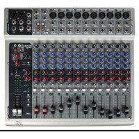

- PV ® 10 • PV ® 14 • PV ® 20
- IMPORTANT SAFETY INSTRUCTIONS
- SAVE THESE INSTRUCTIONS!
- ENGLISH
- PV ® 10, PV ® 14 and PV ® 20
- Compact Mixers
- FEATURES:
- Gain
- ② 80 Hz Low Cut
- Hi EQ
- Mid EQ
- Low EQ
- MON Send (MON Send 2 on the PV®20 only)
- ⑦ EFX Send
- Pan
- Mute
- Clip/Mute LED
- Signal LED
- Fader
- Tape In/Out
- EFX Select
- EFX Time
- Green Signal LED and Red Clip LED
- EFX Return
- EFX Return
- MON Send Master
- EFX Send Master
- Headphone Level
- LED Meters
- Power LED
- Phantom Power LED
- Front Panel
- Phantom Power Switch
- Tape To CTRL/HP
- Tape/to Mix (Tape/USB to Mix)
- Tape/USB to Main (PV®20 only)
- Contour Switch
- Master Level Faders
- Rear Panel
- Line (1/4") Inputs
- Insert
- Stereo (1/4") Inputs
- RCA Inputs
- A/B Switch
- MON Send
- EFX Send
- Control Room Outputs
- Left/Right Outputs
- Headphone Output
- Power Switch
- Removable Power Cord
- NOTE FOR UK ONLY:
- USB port and USB Record Level Control
- PV ® 10, PV ® 14 & PV ® 20 Series Specifications
- Frequency Response
- Total Harmonic Distortion
- Hum and Noise
- Equivalent Input Noise (EIN)
- Crosstalk/Attenuation
- Common Mode Rejection Ratio (Mic Input)
- Meters
- Signal/Overload Indicators
- Dimensions
- Weight
- Power Requirements
- ESPAÑOL
- Descripción
- Medidores
- ⑰ Green Signal LED and Red Clip LED
- Tape to Mix (Tape/USB to Mix)
- Vue Metres
- Puissance requise
- DEUTSCH
- PV ® 10, PV ® 14 Und PV ® 20
- Phantomspeisung-LED
- Tape/ to Mix (Tape/ USB to Mix)
- 中文
- PV®10、PV®14、PV®20
- 便携式混音器
- ⑳ Tape/to Mix (Tape/USB to Mix)
- Tape/USB to Main (PV™20のみ)
- U.S. CUSTOMER WARRANTY REGISTRATION
- Optional Product Extended Warranty Registration
Brand : PEAVEY
Model : PV 10 USB
Category : Audio Mixer