
PC 1600X - MIDI Controller PEAVEY - Free user manual and instructions
Find the device manual for free PC 1600X PEAVEY in PDF.

| Product type | MIDI controller |
| Brand | PEAVEY |
| Model | PC 1600X |
| Power supply | AC adapter 16-16.5 V AC, 1000 mA (Peavey part #70900660) |
| Display | LCD screen 2 lines x 20 characters, adjustable contrast |
| Controls | 16 motorized faders 60 mm, 16 programmable buttons, data wheel, 4 directional buttons, Edit/Utility/Copy/Scene/Enter/Exit buttons |
| Connectors | 1 MIDI input, 1 MIDI output, 2 CV pedal inputs (CV1 and CV2/CV2 dual pedal), power input |
| Main functions | Real-time MIDI parameter control, sending MIDI messages (continuous controllers, program change, notes, SysEx), MIDI data merge/replace/update, MIDI filtering, 100 scenes, 50 programmable factory presets, configuration chains, note recording (chords), remote button emulation via notes or program change, checksum calculation, global parameters (MIDI channel, device ID) |
| Merge modes | Merge, Replace, Update |
| MIDI filtering | Selective filtering of all MIDI message types (notes, controllers, SysEx, etc.) |
| Scenes | 100 scenes to save and recall fader/CV positions |
| Programming | Full programming of faders, buttons, CV inputs, data wheel; ability to name each element; SysEx learn mode; preset initialization |
| Safety | Do not open the device (no user-serviceable parts), use only the supplied adapter, do not expose to rain or moisture |
| Maintenance | Clean with a dry cloth, avoid moisture; refer all repairs to qualified personnel |
Frequently Asked Questions - PC 1600X PEAVEY
User questions about PC 1600X PEAVEY
0 question about this device. Answer the ones you know or ask your own.
Ask a new question about this device
Download the instructions for your MIDI Controller in PDF format for free! Find your manual PC 1600X - PEAVEY and take your electronic device back in hand. On this page are published all the documents necessary for the use of your device. PC 1600X by PEAVEY.
USER MANUAL PC 1600X PEAVEY
Intended to alert the user to the presence of uninsulated "dangerous voltage" within the product's enclosure that may be of sufficient magnitude to constitute a risk of electric shock to persons.

Intended to alert the user of the presence of important operating and maintenance (servicing) instructions in the literature accompanying the product.
CAUTION: Risk of electrical shock - DO NOT OPEN!
CAUTION: To reduce the risk of electric shock, do not remove cover. No user serviceable parts inside. Refer servicing to qualified service personnel.
WARNING: To prevent electrical shock or fire hazard, do not expose this appliance to rain or moisture. Before using this appliance, read the operating guide for further warnings.

Congratulations on your purchase of the PC 1600 × ^TM MIDI Control Station! This is THE MIDI command station for digital workstations, sequencer control or remote MIDI editing. As a matter of fact, the PC 1600x will edit and control just about ANY MIDI device. Fifty factory presets give a good representation of its power, and all fifty are completely user-programmable! MIDI data is transmitted using the following controllers:
- Sixteen programmable 60 mm faders, which can be assigned to transmit continuous controller data (like Volume, Pan, etc.) or any MIDI String (i.e. Channel, System messages). Also, any fader can be the master over any of the other faders. To simplify operation, each fader can be individually named.
- Sixteen programmable buttons, which can be assigned as: fader mute, fader solo, program change, note on/off, MIDI string, MIDI string with button press & release (2 messages), MIDI string toggle (2 messages), fader send, scene send and fader identity. Like the faders, each button can be named. Also, buttons can be accessed remotely via Note or Program Change messages.
- Data wheel - the data wheel can be linked to a fader or Control Voltage input and duplicate its programming. It can also transmit the value of the last fader moved.
- Two Control Voltage Pedal Inputs - the 1600x allows you to plug in and assign CV pedals. These are assigned like the faders. The CV 2 jack can also sub as a dual footswitch input.
The PC 1600x has even more "under the hood!"
100 scenes: Just in case there comes a time when you would like to save your fader's physical position, (like when mixing), the PC 1600x offers 100 scenes that can be saved and recalled as needed. This feature is extremely useful for MIDI light controllers, MIDI mixing, MIDI controllers, etc.
Three Merge Modes: When MIDI connections place the PC 1600x between the source of data (sequencer, etc.) and the destination (tone modules, etc.), it can merge with controller data coming into it in a variety of ways. Three modes are available:
- Merge - Fader movements are merged with incoming data.
- Replace - Same as above, except that when the fader is moved, incoming data is filtered and replaced by data generated by the fader. Fader position determines the value transmitted.
- Update - When the fader is moved, its data matches the last value of the incoming data regardless of fader position. This allows seamless modification of the incoming data.
MIDI Filtering: The PC 1600x contains an extensive MIDI filtering section.
Programmable Set-Up string: Along with all of the fader, button, etc. settings, a MIDI Set-up string can be transmitted when a preset is selected. This string can send Bank select, Program change and Volume settings for ALL 16 channels. In addition, a scene and a MIDI string of up to 80 bytes can be sent.
Easy Synth Programming: The PC 1600x will accept presets pre-programmed for editing. We've made this as "painless" as possible, by designing specific presets for the PC 1600x that are stored in the Spectrum Synth, Spectrum Organ and Spectrum Bass II. You simply transfer them to the PC 1600x, and you instantly have fader and button control over all the parameters. Now, without ever having to deal with hexadecimal SysEx messages, you can edit presets quickly and spend more time getting work done.
The PC 1600x will revolutionize your MIDI set-up! Hook it up to your computer, keyboard, or other MIDI device and take your music to another level.
WHAT'S NEW WITH THE X? 6
FRONT PANEL DESCRIPTION 7
BACK PANEL DESCRIPTION 8
FAST START 9
Connection
Overview
Changing Presets
Sending Current Values
Resetting Replace/Update Mode
Interface 101
UTILITY MENU 12
Navigation
View Angle and MIDI Channel
MIDI Filter
Preset Mapping
Program Change Enable and Current Map Status
Dumping Internal Data
Footswitch Assignments
Device Number and Note Recording Receive Channel
MIDI Transmission Delay
Remote Button Set-up
Individual Preset Initialization
Memory Usage
SCENES 17
About Scenes
Sending A Scene
Storing A Scene
Scene Reset/Initialization
Preset Set-up String Scene Editing
ABOUT PRESETS AND EDITING 19
Initialization/Reset
Unit
Preset
Edit Introduction
Naming and Saving A Preset
Exiting Edit Mode
Accessing Global Setting with Special MIDI Messages
EDITING THE FADERS 21
Defining and Naming
No Message
Continuous Controller
Master Fader/CV
MIDI Strings
Dealing With Checksum Values
Assigning String Device IDs and MIDI Channels to Global Settings
Learn Mode
Saving Your Edits
EDITING THE BUTTONS 25
Defining and Naming
Off/Fader ID (No Message)
Mute/Solo Fader
Program Change
Note On/Off
MIDI Strings
String Prs/RIs
String Toggle
Assigning String Device IDs And MIDI Channels To Global Settings
Responding To Remote Velocity Messages
Learn Mode
Send Fader
Note Stream Recording
Send Scene
Saving Your Edits
EDITING THE CV PEDALS, FOOTSWITCHES, AND DATA WHEEL 31
CV1&CV2
What Type Of Control Voltage Pedal
Footswitch (see Utility section for more information)
Data Wheel
DEFINING THE PRESET SET-UP STRING 32
Bank/Program Change/Volume
About Bank Select
Scene Recall
MIDI String
Learn Mode
COPY MENU 34
Copying From The Main Menu
Copying From The Edit Menu
APPENDIX A: SYSTEM EXCLUSIVE MESSAGES 35
APPENDIX B: PARAMETER FORMATS 37
APPENDIX C: MIDI IMPLEMENTATION CHART 39
APPENDIX D: MIDI CONTROLLER LISTING 40
APPENDIX E: TAKING THE VEX OUT OF HEX 41
APPENDIX F: MIDI 101 43
TRANSLATIONS:
SPANISH 44
FRENCH 80
GERMAN 114
The “X” stands for eXpanded! We’ve started with the popular PC™ 1600 and added extensive new features along with a NEW look!
Expanded SysEx Control
Checksum
Now it is possible to designate a byte as "cs" for checksum calculations.
Global Channel Bytes
Many MIDI products use SysEx messages that include a MIDI channel and/or device ID. This is, of course, handy for differentiating among multiple units of the same type. Normally, changing this byte would require editing of each fader/button individually. Now, a new byte can be a part of the string that specifies the global MIDI setting or global device ID. By simply changing the global setting, all messages are changed.
Expanded Button Facilities
Send Fader
This feature provides an easy way to send specific fader values. When a button is set to "send fader," it must be pressed to enable a fader value to be transmitted. Fader movement is used to select a specific value and the button is pressed to send it. By the way, continuing to hold the button down will enable the fader to work as usual.
Send Scene
This new button function allows any scene to be sent from any of the 16 buttons.
Fader ID
With a button programmed to "Off/Fader ID," pressing the button displays the fader name.
Remote Control
All 16 buttons can now be triggered externally via MIDI notes or program change messages. This is particularly handy for control from a foot pedal.
Note Capture
This makes it easy to capture clusters of notes (chords) and assign them to a button.
Left Arrow (Mute) Button
When the left arrow button is pressed, the PC 1600x will not generate any MIDI messages (only non-filtered messages arriving at the MIDI IN will be echoed).
Preset Initialization
This new utility feature allows a preset to be returned to an initialized state. This is handy for programming from "scratch" or freeing up more dynamically allocated preset memory.
Enhanced Scene Features
Preset Identity
The scene display now indicates the associated preset number.
Scene Initialization
This new scene function allows an existing scene to be initialized, which disassociates it with any preset.
Set-up String Additions
Scenes
A scene can now be assigned to each preset. Any time the preset is recalled, the scene will be transmitted.
Flexible Bank Select
Bank Select editing is now expanded to include MSB or LSB programming.
New Factory Presets
Fifty presets are available that present a wide range of applications.
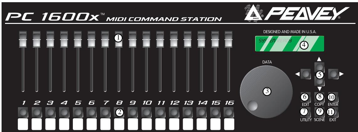
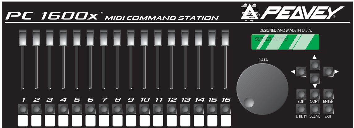
Front Panel
1. 16 Faders
Each of the programmable faders can be assigned the following functions: No Message, Continuous controller, Master fader, MIDI string.
2.16 Buttons
Each of the programmable buttons can be assigned the following functions: Fader ID, Fader mute, Fader solo, Program change, Note-on/Note-off, MIDI String, MIDI String press and release, MIDI string Toggle, Send Fader, Send Scene.
3. Data Wheel
This is a high-resolution device which allows fine adjustment of any fader or control voltage value. The data wheel can be linked to a fader or Control Voltage input and duplicate its programming. It can also transmit the value of the last fader moved.
4. Display Window
This is a 20 character by 2 line Liquid Crystal Display (LCD) with adjustable contrast.
5. Direction Buttons
The up, down, left, and right direction buttons are used to navigate through the user interface. The up/down buttons also serve as increment and decrement buttons to edit parameter values and change presets. The left arrow button also doubles as a MIDI mute button.
6. Edit button
This button accesses all parameters stored within a preset.
7. Utility button
This accesses all global functions of the PC 1600x.
8. Copy button
The Copy button is used to copy from one preset or scene to another. It is also used to copy individual messages.
9. Scene button
Scenes are "snapshots" of the current fader and CV values, in addition to the current preset number. This button is used to save, store, and initialize.
10. Enter button
This button is used to execute functions whenever [Enter] appears in the upper or lower right hand corner of the display. When the main page is displayed, pressing this button sends the current message for each fader and CV input. The display will read "Sending Faders/CVs."
11.Exit button
This button is used to escape from any menu. Pressing Exit several times will always return you to the main page. Pressing Exit from the main menu page can reset the controller filtering of the update/replace merge modes. The display will read "Replace/Update Reset."


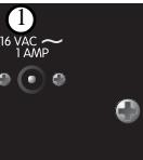


Back Panel
1. Power Supply Input
Use only the 16-16.5 VAC(\~) 1000mA adapter provided. (Peavey part #70900660)

Caution: Use only the 16-16.5 VAC(\~) power supply provided with this product. If the original power supply must be replaced, consult your Peavey dealer or the factory for the correct replacement. Failure to use the correct power supply could result in fire, shock hazard, extensive circuit damage, decreased performance, non-operation, loss of gigs, frustration, cursing, marital problems, and an all-around bad day.
2. Power Switch
3. CV 2 / Footswitch 1 & 2
This input accepts a control voltage foot pedal in addition to a single or dual footswitch. The foot pedal is programmable per preset and functions the same as a fader. Each footswitch can be assigned to one of the following functions: up (inc.), down (dec.), Enter, or duplication of a button (1-16). Polarity is automatically detected at power-up.
4.CV1
This input accepts a control voltage foot pedal and is programmable to function the same as a fader.
5. MIDI OUT
This transmits all data generated internally. This also acts as a MIDI THRU for all unfiltered messages received by the PC 1600x.
6. MIDI IN
This accepts commands to be interpreted by the PC 1600x. It also accepts data to be echoed to the MIDI OUT jack.
This section is designed to get you up and running quickly.
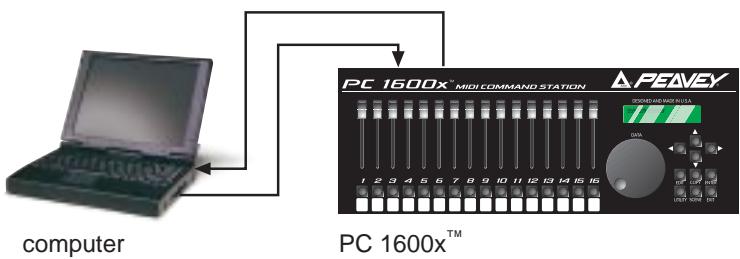
CONNECTION
The PC 1600x^TM MIDI command station is ideal for digital workstations, sequencer control or remote MIDI editing. Your specific application will dictate the proper MIDI connection.
The PC 1600x is connected one of three ways:
Directly to a Device
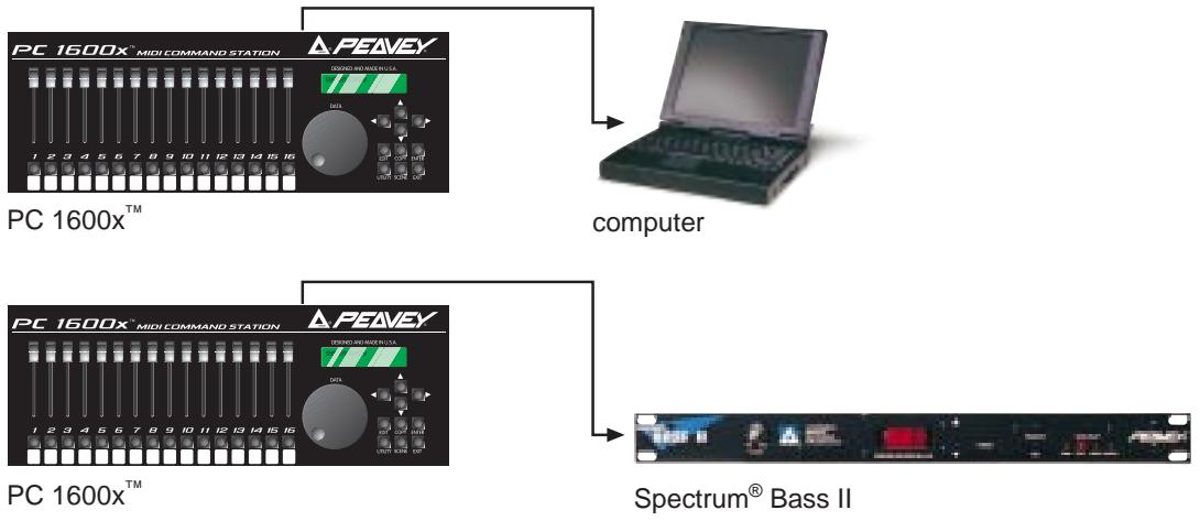
Between Devices
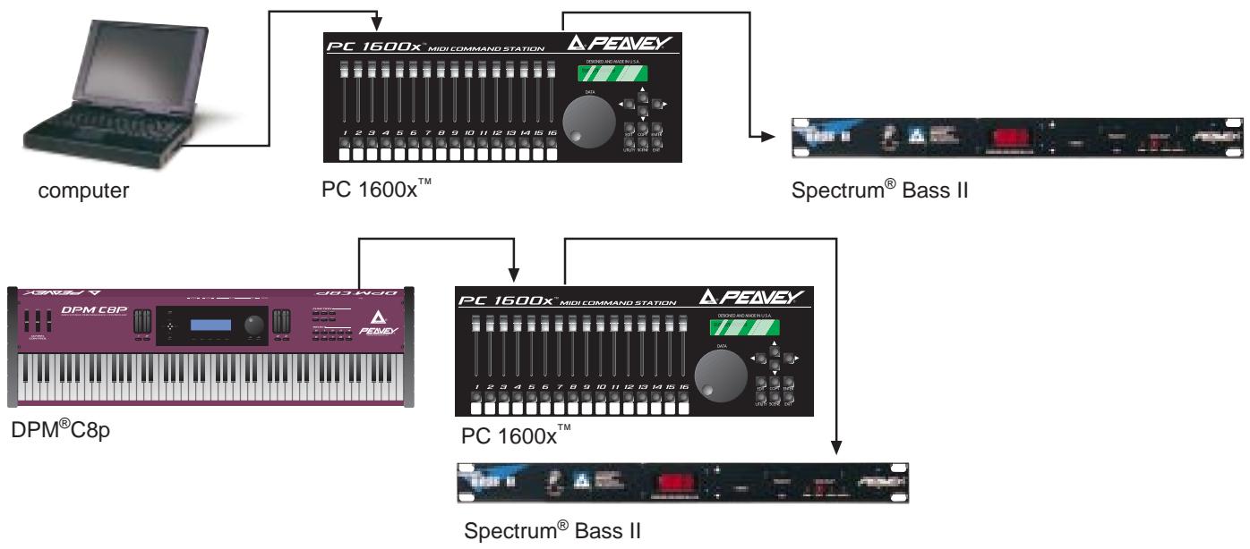
Two-Way
OVERVIEW
The display shown below is an example of the main display of the PC 1600x. Pressing the EXIT button several times will return to this page from any menu. Information shown on this page includes the current preset number, current preset name, and information about the last fader or button moved.
00 Volume with mute Fdr01=01
Changing presets
The PC 1600x has 50 presets, numbered 0-49. The current preset can be changed using the up/down buttons or by an incoming program change when a MIDI map is enabled. A footswitch assigned to duplicate the up/down buttons can also be used to change presets while on this page. Lastly, a system exclusive message can be used to change presets (see Appendix A).
Sending current values
Pressing the Enter button while on the main page will send the current message for each fader and CV input. The display will read "Sending Faders / CVs." This allows the PC 1600x to cancel a soloed fader or update external devices.
An Example:
Suppose the current preset is programmed to send MIDI volumes on each channel and the PC 1600x is connected to a sequencer. Pressing Enter from the main page at the start of a sequence allows all initial volumes of the sequence to be recorded. Simply set the position of all defined faders, start the sequencer recording, then press Enter. All following fader movements will track smoothly from this initial setting.
Resetting Replace or Update Mode with the EXIT button
A fader defined as a continuous controller can be put in a mode that allows it to replace or update a matching controller message passing through the PC 1600x. As soon as the fader moves and sends its message, the PC 1600x begins filtering matching incoming messages. Press the Exit button from the main display page to cancel this filtering allowing the incoming message to pass through the PC 1600x. The display will confirm this operation with "Replace/Update Reset." See page 21 for more information on this feature.

INTERFACE 101
The user interface is based around the 20 × 2 display, and the four navigation/arrow buttons. Like most devices, the PC 1600x is very easy to use as soon as you learn how. Fortunately, with the PC 1600x, the interface is both straightforward and simple to learn. Most features of the PC 1600x can be programmed by understanding only a few basic concepts.
The Edit, Utility, Scene, and Copy buttons are used to access various menus.
The up /down direction buttons serve three major functions:
- When no parameters are flashing, these buttons select different pages within a menu.
- When a parameter is flashing on a particular page, the up/down buttons set the parameter's value. On all pages except the main page, the data wheel has the same function as the up/down buttons.
-
They are used to change presets when on the main page.
-
The left/right direction buttons select the parameter to be adjusted for a given page. If other pages are available within the menu, scrolling past the left-most or right-most parameter causes all parameters to stop flashing.
Note: The up/down and left/right buttons are auto-Scrolling – they will repeat at a fixed rate if you hold one down. To speed up the scrolling, press the opposite direction button after pressing the first (e.g. press and hold the down button, then press the up button to decrement much faster.) - Pressing the Exit button while a parameter is flashing will always stop that parameter from flashing. Pressing the Exit button when no parameter is flashing will always leave the current menu. Several presses of the Exit button will return you to the main page.
The Enter button is used in several places to cause a function to be executed. Except for the main page, "Enter" appears in the upper or lower right-hand corner of the display if it is to be used.
The programmable faders, buttons, and attached CV pedals are all used to transmit MIDI messages. In addition, the data wheel can duplicate the action of a fader or CV input.
NAVIGATION
- Press the Utility button to access the utility pages.
- Use the up/down direction buttons or the data wheel to scroll through the different utility pages.
- When the correct utility page is displayed, use the left/right direction buttons to activate the desired parameter on this page. A parameter is active when the field blinks.
- Use the up/down direction buttons or data wheel to edit the value of the parameter while the parameter is blinking.
- Press the Exit button once or use the left/right direction buttons to de-select (stop all fields from blinking). Now return to step 2 to edit a different parameter, or press the Exit button a second time to return to the main page.
VIEW ANGLE & MIDI CHANNEL
The VIEW parameter adjusts the contrast of the display to allow for different lighting conditions or viewing angles. To adjust the view angle:
- Press the Utility button.
- If not displayed, use the up/down buttons or data wheel to access the following page:
| UTIL: View | ChIn | ChOut |
| 0 | 01 | 01 |
- Cursor right once to activate the "View" field and use the up/down direction buttons or data wheel to edit the view angle.
Separate MIDI channels can be set for incoming MIDI messages and transmitted MIDI messages. The "ChIn" parameter is used to set the receiving MIDI channel of the unit. The PC 1600x^TM will only respond to incoming messages received on this channel. The "ChOut" parameter is used to set the transmitting channel of the unit. Any messages set to transmit on the main channel use this parameter. Use the same procedures listed above to access the MIDI parameters.
Note: For the PC 1600x to receive the SysEx messages as listed in Appendix A, the ChIn value set on this screen must match the channel byte in the message.
Many devices use SysEx command strings that include a MIDI channel or device number as one of the bytes. This practice is beneficial to the user since it allows separate SysEx control when differentiating one unit from an identical unit on the same MIDI stream.
Instead of hard-coding these values into the strings, a "gc" (global channel) or "dv" (device number) byte can be designated that references the global setting. By altering this Utility setting, all strings can be altered simultaneously. When the PC 1600x sees a "gc" in the string, it will transmit the ChOut setting. When it sees a "dv" in the string, it will transmit the DevNum variable (see the "Device Number..." section in this chapter).
MIDI FILTER
Selecting which MIDI messages will pass from MIDI IN to MIDI OUT is handled by the MIDI filter utility. Individual messages or all MIDI messages can be filtered, allowing only certain incoming messages to pass to the MIDI OUT. The following messages can be filtered:
All MIDI (overrrides all others when set to filter)
All Notes
Mod Wheel
Foot Pedal
Volume
Sustain
Reset Controllers
All Notes Off
Program Change
- Polyphonic Aftertouch
- Channel Aftertouch
Pitch Bend
System Exclusive
System Common
System Real-time
To set the status of a filter:
- Press the Utility button.
- Use the up/down buttons or data wheel to access the following page:
UTIL: Midi filter Notes=Pass
- Press the right direction button once to edit the filter type. Use the up/down buttons or data wheel to display the different filter types. The field on the right displays whether the data is filtered or passed to the MIDI OUT jack.
- To toggle between "pass" and "filter," simply press the right direction button while the filter type field is active. The filter type field remains active until the left direction or Exit button is pressed.
PRESET MAPPING
In its default state, the PC 1600x^TM will echo Program Changes, but not respond to them. To make it respond, you must go to the "MAP: Curr Midi map" screen and switch on one of the three maps (instead of "Off"). Then the PC 1600x will respond to Program Changes on its MIDI IN channel ("ChIn" parameter on the first utility screen) according to the map. Mapping allows each of the 128 MIDI program change messages (0-127) to recall any preset or send any scene. Follow the steps below to select which preset is recalled or which scene is sent in response to a received program change message:
- Press the Utility button.
- Use the up/down buttons or data wheel to access the following page:
MAP1:Prog000->prs00 Preset name here
- First cursor right to the digit after "MAP." Editing this value selects which MIDI map will be edited. This should not be confused with the current MIDI map described below.
- Cursor right again to the third field which displays a preset or scene number. This is the preset number recalled or scene sent when the program change value in the second field is received. If a preset is selected, the bottom line will display the preset name. When a scene is selected, the associated preset number will be displayed.
Note: Program change maps 1 and 2 default to recall presets 0-49 with received program changes 0-49. Program change map 3 defaults to send scenes 0-99 with received program changes 0-99.
PROGRAM CHANGE ENABLE AND CURRENT MAP STATUS
The current MIDI map parameter selects which map incoming program changes will use. Incoming program changes can be ignored completely by setting the current map number to "Off." To set the current map number:
- Press the Utility button.
- Use the up/down buttons or data wheel to access the following page:
MAP Curr MIDI map Off
- Cursor right once to activate the field and use the up/down direction buttons or data wheel to edit the map number.
- To ignore all incoming program changes, decrease the current map number until "Off" is displayed.
DUMPING INTERNAL DATA
All internal data can be transmitted over MIDI to be saved on an external device. The MIDI Dump page allows the following data to be transmitted:
All presets
All scenes
All global variables
The current preset
- Everything
To transmit this information:
- Press the Utility button.
- Use the up/down buttons or data wheel to access the following page:
UTIL:Dump [Enter] Everything
- Cursor right once to activate the field and use the up/down direction buttons or data wheel to edit the type of data to be transmitted.
- Press the Enter button to transmit the data.
Note: Data dumps can also be requested remotely using the appropriate SysEx message (see Appendix A.)
ASSIGNING FOOTSWITCHES
A footswitch can be assigned globally to duplicate most of the front panel buttons on the PC 1600x. Examples of footswitch uses include:
Changing presets on the PC 1600x by assigning the footswitches to "Inc." or "Dec."
Saving and sending scenes by assigning a footswitch to copy the Enter button.
- Starting and stopping a sequencer by assigning a button to toggle between start and stop messages and assigning the footswitch to copy that button.
- Sending note messages to drum machines allows drum parts to be played with a footswitch. Assign a button to send a note message and assign a footswitch to copy that button.
- Muting an effect by duplicating a button message that mutes a fader.
To assign a footswitch:
- Press the Utility button.
- Use the up/down buttons or data wheel to access the following page:
UTIL: Ftsw1 Ftsw2 Off
-
Select the correct footswitch field using the left and right direction buttons.
-
Use the up/down buttons or the data wheel to select which button the footswitch will emulate.
The polarity of the footswitch is automatically determined on power-up. If a footswitch is installed after the PC 1600x is powered up, or if the footswitch is depressed during power-up, the polarity of the footswitch may be incorrect. Simply switch the power off, wait a few seconds, and turn the power back on with the footswitch installed but not pressed. This will correct the polarity.
Note:Assigning a footswitch will automatically disable the CV 2 input.
DEVICE NUMBER - NOTE RECORDING/RECEIVE CHANNEL

This screen allows the assignment of a global device ID. Many MIDI products use system exclusive command strings that have a device number as one of the bytes. These numbers are used to differentiate the unit from an identical unit on the same MIDI stream. Being able to change these numbers globally allows you to use one set of PC 1600x presets for multiple units of the same product. Instead of hard-coding these values into the strings, it is possible to designate a 'dv' (device number) byte in the strings, then adjust this parameter to function as the global setting.
The RecChn parameter is used when recording note messages into button strings. The Note Recording Receive Channel parameter simply determines which channel notes will be accepted on. For more information, check out the Note Stream Recording section on page 28.
MIDI TRANSMISSION DELAY
Sometimes a device can't handle MIDI data as fast as the PC 1600x can generate it. This can happen when sending scenes, dumping presets, or during any other operation that sends large amounts of data. There are two types of MIDI delay available to you. They both default to zero, and shouldn't be set otherwise unless a problem is occurring with a receiving unit.
The first is a per-SysEx message delay, which is inserted after the PC 1600x sends an EOx byte (F7h). This puts delays in between SysEx messages. The delay can be set from 0 to 100 ms. Try raising this number in 5 ms steps if a unit chokes on SysEx data from sending scenes. (By "choking" we mean that the unit got a MIDl receive error, got hung, or just didn't do everything that it should have.) Don't set this number higher than needed. The maximum value of 100 ms will make a scene with 16 SysEx messages take almost 2 seconds to send.
The other type of delay is a per-byte delay, which is inserted after every byte that the PC 1600x sends. This delay can be set from 0 to 1000 us (1 ms), in 10 us steps. If a computer or MIDI librarian is getting a buffer overflow when you're backing up your PC 1600x data, try setting this delay between 100 and 500 as needed. (A value of 320 will essentially split the MIDI speed in half.) You'll probably want to lower the delay when you're done, and only raise it when needed.
The Delay screen is displayed as follows:

NOTE: These delays only affect MIDI data that the PC1600x generates internally. Data that is echoed from MIDI IN to MIDI OUT is not delayed.
REMOTE BUTTON SET-UP
The 16 programmable buttons are useful for sending any type of message to just about any MIDI device. You can access the button messages remotely by sending simple messages into the PC 1600x. All you need is a MIDI keyboard, pedal board, or any other MIDI controller that sends Program Change commands or MIDI Note On/ Note Off messages (e.g. "MIDI-fied" foot pedals). For example, use your note pedals to play chords instead of
single notes (with pre-programmed velocity or the velocity from the pedals). Reserve keys on your keyboard for sending SysEx messages. Or, use your Program Change pedal board to send more complex MIDI messages (like SysEx or multiple Program Changes). The possibilities are virtually unlimited.
Move to the utility screen displayed below. Pick the emulation type (Off, Notes, PrgCh), the MIDI channel you are sending these messages on (1-16), and the starting value (0-127). The starting value is the base note number or base program number, depending on the emulation type. The base value will emulate button #1, while the next 15 values will emulate buttons #2-#15. The incoming message will not be echoed, even if the button is "Off." (NOTE: Middle C on a MIDI keyboard is note number 60 [3Ch].)
| BUTN: | Type | Ch | Start |
| REMT | Off | 01 | 000 |
When the type is set to "Notes," Note On messages will emulate a button press, while Note Off messages (including Note On with velocity = 0 , of course) will emulate a button release. In "PrgCh" mode, Program Change messages will emulate a button press immediately followed by the release. (You probably won't find much use for a prs/rls string when emulating in PrgCh mode — use normal or toggled strings instead.)
INDIVIDUAL PRESET INITIALIZATION
When creating new presets, it is perfectly fine to edit existing presets. However, if you prefer to start with a "clean slate," a preset initialization function is available in the utility menu.
- Press the Utility button
- Use the up/down buttons to move to the following screen:
| UTIL: Init a Preset 00 Volume with mute |
- Select the preset number you wish to re-initialize.
- Press ENTER, then you will be asked, "ARE YOU SURE?"
- Press ENTER again to confirm initialization. The preset will be renamed "—initialized—".
Note: All presets share the same block of memory, which gets divided among the available presets. This utility is very handy for freeing up memory since you can reinitialize presets that are not needed.
MEMORY USAGE
PC 1600x presets are dynamically allocated, allowing a single preset to be very large when necessary. If too many large presets are created, the PC 1600x will run out of preset memory. When this occurs, some memory must be freed by removing (reinitializing) or re-defining presets. The memory usage display helps determine which presets to modify. To use the memory usage display:
- Press the Utility button.
- Use the up/down buttons or data wheel to access the following page:
| UTIL: | Memory |
| Free: 6324 |
- Press the left or right button to activate the field.
- Use the up/down buttons or the data wheel to view the amount of free memory and the amount of memory used by each preset.
Note: The names of faders, CV inputs, and buttons only use memory per character, therefore shortening the names frees up memory. Preset names, however, have a fixed length, so this wouldn't apply.
ABOUT SCENES
A scene allows a "snapshot" to be taken of the current preset number, fader positions & CV settings. These are saved in one of the 100 scene locations. Sending a scene will transmit the information for each fader/CV pedal just as it was saved. The scene will be sent referencing the preset that was active when the scene was saved, not the preset active when the scene is sent.
Example:
If the current preset is configured to control digital tracks, each fader can be used to adjust the mix on a specific track. When all faders are set to a desired setting, save this as a scene. Continue to adjust the faders and save scenes as necessary. During a performance, the scenes saved can easily be sent to the mixer/recorder/sequencer system even if a different PC 1600x preset is being used.
Repeatedly pressing the Scene button will toggle between the SCENE Send, Store, and INITIALIZE pages.
Note: The original preset that was active when the scene was saved must still be in the same preset location within the PC 1600x for the correct messages to be transmitted.
SENDING A SCENE
- Press the Scene button until the following page is displayed:
| SCENE: | Send | [Enter] |
| [p:---] | 00 |
- Use the up/down direction buttons or the data wheel to select a scene. Note: The associated preset is indicated in the lower left corner in parentheses.
- Press the Enter button to send the scene. The scene will be sent using the preset which was current when the scene was saved. The scene number will automatically increment to the next scene, allowing several scenes to be sent quickly.
STORING A SCENE
- Recall the desired preset to be used.
- Set all faders and CV inputs to the correct positions.
- Press the SCENE button until the following page is displayed:
| SCENE: Store [Enter] [p----] 00 |
- Use the up/down direction buttons or the data wheel to select the scene number to save. Note: The associated preset is indicated in parentheses in the lower left corner.
- Press the Enter button to save the scene. The scene number will automatically increment to the next scene, allowing several scenes to be stored quickly.
Note: A scene saves the current position of each fader and CV input. Data wheel movements and soloing/muting a fader have no effect on the data stored in a scene or sent by a scene.
SCENE INITIALIZE
Allows an existing scene to be initialized, which disassociates it with any preset, therefore making it send nothing. This screen is displayed as follows:
-
Press the Scene button until the following page is displayed:
-
Use the up/down direction buttons or the data wheel to select a scene. Note: The associated preset is indicated in parentheses in the lower left corner.
- Press the Enter button to initialize the scene. The scene number will automatically increment to the next scene, allowing several scenes to be initialized quickly.
Pressing ENTER will clear any values recorded by a stored scene. After initialization, the preset link will change to "p:—." Of course, if at first you see [p:—], the scene is already initialized.
PRESET SET-UP STRING SCENE EDITING
A scene can be assigned to each preset. When this condition exists, any time the preset is recalled, the scene data will be transmitted. Since the memory area for scene storage is fixed and separate from the preset memory, this function provides an efficient way to transmit data. For more information, see the preset set-up string info on page 32.
Each preset contains a variety of information:
16 fader messages
16 button messages
2 CV messages
A group of "set-up" messages that are transmitted each time a preset is selected/recalled.
*Data Wheel Link
Fifty unique presets are available for editing. However, we have pre-programmed each of them with a variety of sample presets to give you application examples.
UNIT INITIALIZATION:
Initialization restores all 50 factory presets (and erases any settings you might have made), resets the global settings, and deletes any programmed scene settings. If you're sure you want to do this, use the following procedure:
- Turn power off.
- Hold the Utility and Enter buttons while turning the power on.
- "Memory Initialized" is displayed.
Note: It is not possible to undo the initialization procedure.
INDIVIDUAL PRESET INITIALIZATION
When creating new presets, it is perfectly fine to edit existing presets. However, if you prefer to start with a "clean slate," a preset initialization function is available in the utility menu.
- Press the Utility button.
- Use the up/down buttons to move to the following screen:
UTIL: Init a Preset] 00 Volume with mute
- Select the preset number you wish to re-initialize.
- Press ENTER, then you will be asked, "ARE YOU SURE?"
- Press ENTER again to confirm initialization. The preset will be renamed "— Initialized—"
Note: All presets share the same block of memory, which gets divided among the available presets.
This utility is very handy for freeing up memory since you can reinitialize presets that are not needed. The Memory Usage page is also in the Utility Menu.
EDIT INTRODUCTION
Access the main edit page at any time by pressing the Edit button. The field on this page selects the item to be edited. The following choices are available:
Fader 01 - Fader 16
CV1,CV2
- Button 01 - Button 16
Data wheel
- Set-up string
Name/Save preset
The up and down direction buttons or the data wheel can be used to scroll through the above choices. Moving any fader, CV input, or button will cause that item to be displayed. When the desired item is displayed, press the Enter button to access the parameters specific to that item.
Shortcut: For a time-saving shortcut, try moving a fader, CV input, button, or the data wheel while holding the edit button. Releasing the edit button will immediately access the selected item.
"Sideways/Navigation" is possible when switching to a device that is set to the same function. This will allow you to jump to a different device and be at the same screen as the previous device.
NAMING & SAVING A PRESET
Go to the Edit menu. Use the Data Wheel or up/down arrow keys to move to the "Name/Save prs" page. Press ENTER. Use the left/right direction buttons to select the character in the name and the up/down buttons or data wheel to edit the character. To make editing faster, each fader edits a different character of the name. Pressing ENTER from this page accesses the "SAVE TO" page. The bottom line of this page displays the number and name of the destination preset to be overwritten. The data wheel and up/down buttons may be used to change the storage destination. Pressing the Enter button from this page will save the preset and return to the main page. By pressing the Exit button, you will be returned to the "Edit name" page.
EXITING EDIT MODE
To return to the main page at any time, press Exit several times until the main page is reached. If changes were made to the preset, the preset number will be replaced with **. This is an indication that the preset in the edit buffer has been modified but not saved. Press Edit to return to the Edit mode if the changes are to be saved. Changing presets results in the following display:
[Enter] Exit without saving?
Press ENTER to confirm that you don't want to save your edits. Press up/down from the main page to leave this preset. This will cause any changes that were made to be discarded. However, if you don't edit another preset, recovery is possible. Edits which were discarded can be recovered from the main page. Increment the preset number above preset 49 and the preset number is replaced by **. Pressing Edit returns to the Edit mode with the edit buffer exactly as it was last time the Edit mode was exited (even if the unit had been powered down. Amazing!)
ACCESSING GLOBAL SETTINGS WITH SPECIAL MIDI MESSAGES
Many MIDI products use system exclusive command strings that have a MIDI channel or device number as one of the bytes. These numbers are used to differentiate the unit from an identical unit on the same MIDI stream. Being able to change these numbers allows you to use one set of PC 1600x^TM resets for multiple units of the same product.
Instead of hard-coding these values into the strings, you can designate a 'gc' (global channel) byte or a 'dv' (device number) byte in the strings, then just go to UTILITY and change the ChOut (1st screen) and DevNum (7th screen) parameters.
Whenever the PC 1600x sees a 'gc' in a string, it will transmit the ChOut parameter minus 1 (0 - 15 [0Fh]). When it sees a 'dv', it will transmit the DevNum parameter (0-127 [7Fh]).
Additionally, the 'gc' designation can be placed after a channel status byte (80h through EFh). In this case, the 'gc' will channelize the status byte, as opposed to it being sent as a separate byte. The status and 'gc' bytes will be connected by a hyphen to show that they are being combined into a single byte upon transmission. The following screen would program fader #1 to send Program Changes on the global out channel. The zero after the C will get replaced by ChOut - 1 (0 - F), therefore making it meaningless (a CF would make no difference to the fader function).
FDR01: String C0-gc pr
To program one of these values in a string (fader, CV, button, or set-up), edit the byte value up to FD or FE, at which point you will see 'dv' or 'gc' on the display, respectively (instead of 'FD' or 'FE').
NOTE: In button and set-up strings, the first byte of the string cannot be a 'dv' or 'gc.' This allows the user to send the raw values FDh (undefined) and FEh (active sensing) over MIDI, if desired, by programming them as the first byte.
DEFINING AND NAMING
When a fader is selected to be edited, the first page displayed selects the function of the fader. A fader can be assigned to the following functions:
No message
Continuous controller
Master fader
MIDI string
To set the function of a fader:
- Access the following fader function display by pressing Edit from the main page, then moving fader 01. Next, press ENTER.
FDR01: Function No message
- Cursor right to select the function for the fader (it will blink). Press the up/down buttons to access any of the four choices: No message, Controller, Master fader, or String.
- Press EXIT to de-select the item. Except when "No message" is selected, access to additional parameters and naming for this fader is available by pressing the up direction button (when the function field is not blinking).
After assigning a function to the fader, the fader can be named. To name the fader:
- With no parameters flashing, press the up direction button until the following page is displayed.
FDR01: Name
- Use the left/right direction buttons to select the character in the fader name. Next, press the up/down direction buttons, data wheel, and/or the current fader to change (edit) the character.
NOMESSAGE
A fader can have its function set to “No message.” With this option, moving the fader will (of course) have no action.
CONTINUOUS CONTROLLER
A fader can be programmed to send a continuous controller message whenever the fader moves. The MIDI channel can be set to any specific channel, or to the main transmit channel set in the Utility section. The controller number can be set to any value from 0 to 120.
The "Min" parameter determines the value sent when the fader is in its lower-most position next to the button. The "Max" parameter determines the value sent when the fader is in its upper-most position. Simply exchange the values in these two parameters to reverse the polarity of a fader.
The "mode" parameter determines how matching incoming controller messages will be handled. The three modes are as follows:
Merge:
Incoming controller messages that match a fader are always passed through the PC 1600x. The MIDI data generated from fader movement is merged with the data passing through the unit.
Replace:
Incoming controller messages that match a fader are passed through the PC 1600x until the fader is moved. The matching incoming controller messages are filtered until the Exit button is pressed while on the Main page. This mode allows direct replacement of data in an existing stream of controller messages.
Update:
Incoming controller messages that match a fader are passed through the PC 1600x until the fader is moved. The data sent when the fader first moves will always match the last value that passed through the PC 1600x, regardless of the position of the fader. The matching incoming controller messages are filtered until the Exit button is pressed while on the Main page. This mode allows seamless modification of data in an existing stream of controller messages.
To define a fader as a continuous controller:
- First, set the function to "Controller." Press the left, right, or Exit button to de-select the edit field, then press the up button to move to the following page:
FDR01: Chnl Num 16 007
- Cursor over to the "Chnl" field and set the MIDI channel for the controller message. incrementing the channel number above 16 will display "ChOut." When "ChOut" is selected, the controller message will be transmitted on the global MIDI transmit channel from the Utility menu.
- Cursor over to the "Num" field to set the controller number to be transmitted. See Appendix C for a list of MIDI Controller numbers.
- With no parameters flashing, press the up direction button to access the following page:
FDR01: Min Max 000 127
- Cursor left or right to the Min or Max field and edit the value as necessary (range=0-127).
- With no parameter flashing, press the up direction button to access the mode page:
FDR01: Mode Merge
- Cursor right or left to access the "Mode" parameter. Select either "Merge," "Replace," or "Update."
MASTER FADER/CV
Several faders can be grouped together and controlled by another fader. This is done by defining a single fader or CV pedal as the master fader as shown:
- Set the function to "Master Fader". Next, press the up direction button when the function field is not blinking. The following page will be displayed:
FDR01: Master of Fader01= No
- Cursor right once to activate the "Master of" field. Set this field using the up/down direction buttons, the data wheel, or the current fader. Moving any fader will select the fader moved.
- The "Yes" or "No" on the right shows whether the fader in the "Master of" field is being controlled by the current master fader. To toggle between "Yes" and "No," simply press the right direction button. The "Master of" field will remain active.
MIDI STRINGS
Any MIDI message can be assigned to a fader by entering the message as a hexadecimal string. A flexible "parameter format" allows the current fader position to be inserted into the message in one of many different formats. A programmable minimum and maximum parameter value allows the parameter to span practically any range. To define a MIDI message string:
- Select the function "String." Next, press the up direction button when the function field is not blinking. The following page will be displayed:
FDR01: String
F0 00 F7
- To edit the string, use the four direction buttons, the data wheel, and the current fader. The left /right direction buttons are used to select a specific byte, while the up/down direction buttons, the data wheel, and the current fader are used to edit a digit of the string. Pressing the up button when between bytes inserts a byte and pressing the down button deletes the byte to the right of the cursor.
- Replace with "pr" any byte that will be determined by the fader position. This is done by incrementing the byte until "pr" is displayed. When the string is finished, press Exit.
- Access the minimum and maximum parameters by pressing the up direction button when the underscore cursor is not displayed.
FDR01: Min Max 0 127
- Cursor over to either parameter and edit the value. Use the fader to set the parameter to the approximate value necessary. Use the data wheel or the up/down buttons to enter the exact value.
- When neither field is flashing, press the up direction button to access the parameter format page:
FDR01:Param format Single Byte
- The value selected here determines how the "pr" bytes will be filled with the parameter value. Refer to your unit's owner's manual to determine which format to use. For a detailed description of the parameter formats, see Appendix B.
DEALING WITH CHECKSUM VALUES
Some products call for checksum bytes in their SysEx implementation. In order to specify a byte as checksum, a "cs" can be added to the string. To program, just edit the byte up to what would normally be FC. Displayed in its place will be "cs." Here is an example string with an extended display to show you the entire string:
FDR01: String
F0 41 10 70 12 00 00 01 pr cs F7
The PC 1600x^TM will compute the checksum as follows:
Adds up all bytes from byte #5 (or higher, see below, when F0 is byte #0) to the last byte before the "cs." Note: byte #5 is typically the start of the data portion of the SysEx.
Takes the 2's complement (flips all the bits, then add 1).
*Uses the least significant 7 bits of the result as the checksum byte. The 8th byte is always zero.
With some SysEx messages, the unit ID (byte #3), and command ID (byte#4) could be extended beyond a single byte by using leading zeroes before the non-zero byte. In this case, the PC 1600x's checksum calculation will start later in the string accordingly: at byte # (5 + number of leading zeroes). Note: The "cs" computation is unavailable in button and set-up strings. In these cases, the checksum must be calculated and inserted into the string as a constant by the programmer. Be sure and refer to your product owner's manual for the necessary values/mes-sages.
ASSIGNING STRING DEVICE IDs AND MIDI CHANNELS TO GLOBAL SETTINGS
Many devices use SysEx command strings that include a MIDI channel or device number as one of the bytes. This practice is beneficial to the user since it allows separate SysEx control when differentiating one unit from an identical unit on the same MIDI stream.
Instead of hard-coding these values into the strings, a "gc" (global channel) or "dv" (device number) byte can be designated that references the global settings in the Utility section. When the PC 1600x^TM sees a "gc" in the string, it will transmit the Utility menu's ChOut setting. When it sees a "dv" in the string, it will transmit the DevNum variable.
Additionally, the "gc" designation can be used with MIDI Channel messages. In this case, the "gc" will channelize the preceding byte, as opposed to being sent as a separate byte. For display, the status and "gc" bytes are connected by a hyphen to show that they are being combined into a single byte. The following example is how this would be displayed:

The zero after the C will get replaced by the ChOut setting in the Utility menu.
LEARN MODE
If a system exclusive message is received while a fader string is being edited (the underline cursor must be present), the PC 1600x will automatically replace the existing fader string with the system exclusive message received.
SAVING YOUR EDITS
Use the following steps to save your edits:
- Press the Edit button.
- Use the data wheel or up/down buttons to scroll to the last option: Name/Save preset.
- Press Enter.
- To re-name, use the left/right buttons to select character positions and the up/down buttons to edit the character. Note: Faders also can be used to select character positions.
- Press Enter.
- Choose the destination for the save with the up/down buttons or the data wheel.
- Press Enter to save to the location displayed at the bottom of the display.
To return to the main page at any time, press Exit several times until the main page is reached. If changes were made to the preset, the preset number will be replaced with **. This is an indication that the preset in the edit buffer has been modified but not saved. Press Edit to return to the Edit mode if the changes are to be saved. Press up or down from the main page to leave this preset. This will cause any changes that were made to be discarded.
Note: Edits which were discarded can be recovered from the main page if no other preset has been edited (even after a power down). Increment the preset number above preset 49 and the preset number is replaced by “**”. Pressing Edit returns to the Edit mode with the edit buffer exactly as it was last time the Edit mode was exited.
DEFINING AND NAMING
When a button is selected to be edited, the first page displayed selects the function of the button. A button can be assigned to the following functions:
- Off/Fader ID
Mute fader
Solo fader
Program change message
Note on/off message
MIDI string - MIDI string with button press, MIDI string with button release
- Toggle between two MIDI strings
Send Fader
Send Scene
To set the function of a button:
- Press EDIT, then press a button to select it (in this example, button 16. Press Enter to access the following page.)
BTN16: Function Off / Fader ID
- Press the right direction button to select the function (it will blink), then use the up/down buttons or data wheel to select the desired function.
- Use the up direction button when the function field is not blinking to access other parameters. Press either of the left/right direction arrows (or exit) to de-select (stop the blinking).
After assigning a function to the button, the button can be named. To name the button:
- With no parameter selected and a function other than "Off / Fader ID" selected, press the up direction button until the following page is displayed:
BTN16: Name
- Use the left/right direction buttons to select the character in the button name and the up/down direction buttons, the data wheel, and/or the fader above the button to edit the character.
OFF/FADER ID (NOMESSAGE)
Whenever one of the 16 programmable buttons is programmed as "Off / Fader ID" it will identify its associated fader when on the top of the preset screen. For example, pressing button 16 would cause the PC 1600x to display "Fdr16 :
MUTE/SOLO FADER
A button can be assigned to mute the associated fader. Pressing the button will mute the fader by sending the minimum value for the fader, and then disable the fader. When muted, moving the fader will have no effect. When the button is pressed again, the current fader message is sent, and the fader is enabled. To program a button to mute the associated fader, simply select "Mute fader" for the button function.
A button can be programmed to solo the associated fader by simply selecting the "Solo fader" function for the button. With this function, pressing the button will send the minimum value for each fader except the button's
associated fader. To restore any fader, simply move the desired fader. To cancel the solo entirely, simply press the Enter button with the main page displayed.
PROGRAM CHANGE
A button can be assigned to send a program change message each time it is pressed. The MIDI channel can be set to any MIDI channel, or to the main transmit channel set in the Utility section. The program number can be any value from 000 to 127. To set these two parameters:
- From the button function page, select "Program Chng." Next, de-select, then press the up direction button. The following page will be displayed:
| BTN16: Chnl 01 | Program 000 |
- Cursor over to the "Chnl" field and set the MIDI channel for the program change message.
Incrementing the channel number above 16 will display "ChOut." When "ChOut" is selected, the gram change message will be transmitted on the global MIDI channel set in the Utility menu.
pro-
- Cursor over to the "Program" field to set the program number.
NOTE ON/OFF
A button can be assigned to send a note-on message when the button is pressed, and a note-off message when the button is released. The MIDI channel can be set to any specific channel, or to the main transmit channel set in the Utility section. The note number can be set to any note from C-1 to G9. The velocity can be set to any specific value (1-127), determined by the current fader position (Fdr), or determined by incoming MIDI velocity (Rem) when button remote is used. To set the parameters:
- From the button function page, select "Note-on/off." Next, de-select then press the up direction button. The following page will be displayed:
| BTN16: | Chnl | Note | Vel |
| 01 | C4 | 127 |
- Cursor over to the "Chnl" field and set the MIDI channel. incrementing the channel number above 16 will display "ChOut", which references the global MIDI channel.
- Cursor over to the "Note" field to set the note number.
- Cursor over to the "Vel" field to set the velocity value. incrementing the velocity value above 127 will display "Fdr." This option allows the current position of the fader to set the note-on velocity. Pressing the up button again will display "Rem." This substitutes the incoming MIDI velocity when the button is activated via a MIDI "note on" message. When pressed locally, "Rem" will act like the "Fdr" setting and velocity will be determined by fader position.
MIDI STRINGS
A button can be assigned to transmit just about any MIDI message when pressed. These messages are entered in hexadecimal form or captured via MIDI (see "Learn Mode" on page 24). To define a button MIDI string:
- From the button function page, select "String." Next, de-select and press the up direction button. The following page will be displayed:
| BTN16: | String |
| F0 00 F7 |
- Use the left and right direction buttons to select a byte to be edited. When the cursor is on a digit, the up/ down direction buttons, data wheel, and/or associated fader will edit the digit. Pressing the up button when between bytes inserts a byte, and pressing the down button between bytes deletes a byte.
STRING PRS/RLS
A button can be assigned to transmit any MIDI messages when pressed and any other MIDI message when
released. These messages are entered in hexadecimal form. To program the press and release string:
- From the button function page, select "String prs/rls." Next, de-select, then press the up direction button. The following page will be displayed:
BTN16: Press String
F0 00 F7
- Enter the MIDI string.
- After editing the "Press String," press Exit. Press the up direction button to move to the release string displayed as follows:
BTN16: Rls String F0 00 F7
- Enter the release string.
STRING TOGGLE
A button can be assigned to toggle between any two MIDI message strings. These messages are entered in hexadecimal form. To program the two strings:
- From the button function page, select "String toggle." Next, de-select then press the up direction button. The following page will be displayed:
BTN16: String 1
F0 00 F7
- Enter the first string.
- Exit from editing the first string then press the up direction button to edit the second string displayed as follows:
BTN16: String 2
F0 00 F7
- Edit the second string as necessary.
ASSIGNING STRING DEVICE IDS AND MIDI CHANNELS TO GLOBAL SETTINGS
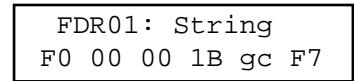
Many devices use SysEx command strings that include a MIDI channel or device number as one of the bytes. This practice is beneficial to the user since it allows separate SysEx control when differentiating one unit from an identical unit on the same MIDI stream.
Instead of hard-coding these values into the stings, a "gc" (global channel) or "dv" (device number) byte can be designated that references the global settings in the Utility section. When the PC 1600x sees a "gc" in the string, it will transmit the Utility menu's ChOut setting. When it sees a "dv" in the string, it will transmit the DevNum variable.
FDR01: String
F0 00 00 1B gc F7
Additionally, the "gc" designation can be used with MIDI Channel messages. In this case, the "gc" will channelize the preceding byte, as opposed to being sent as a separate byte. For display, the status and "gc" bytes are connected by a hyphen to show that they are being combined into a single byte. The following example is how this would be displayed:
FDR01: String C0-gc pr
The zero after the C will get replaced by the ChOut setting in the Utility menu.
RESPONDING TO REMOTE VELOCITY MESSAGES
When using "Notes" mode (the Button Remote page in the Utility menu is set to Type=Notes), to play MIDI notes
or chords, the PC 1600x (per note!) can be programmed to use a fixed velocity, or to use the velocity that comes in via MIDI (e.g. from velocity-sensitive note pedals or keyboards). If the button is programmed as a single note, set the velocity variable to "rv" for Remote. This is one example:
BTN16: String 90 60 rv
If playing a chord (a button is programmed to transmit several notes via a MIDI string), edit the string and set the velocity bytes up to FF, which accesses 'rv' (remote velocity) in the string instead of the FF. Whenever the PC 1600x sees an 'rv' in a button string, and the most recent status byte in the string was a Note On (9x, for attack velocity) or Note Off (8x, for release velocity), it will substitute the incoming velocity.
If the button is programmed to transmit a single note on message using the button "note on" function (vs. a MIDI String), the screen would be displayed similar to this:
BTN16:Chnl Note Vel 01 C4 Rem
As mentioned earlier, the "Rem" designation indicates that velocity will be determined from remote MIDI input. If a button is pressed locally (on the PC 1600x itself), or a Program Change is received, the 'rv' byte value (or "Rem" setting) will be determined by the position of the fader above the button, even if it did not follow a 9x or an 8x. The fader position number will always be ranged from 0-127 (or 1-127 if within a note stream). It will not be affected by the fader's Min and Max parameters.
NOTE: Since the 'rv' velocity will use the fader position when the button is pressed on the PC 1600x, it is useful to use 'rv' even when not using the remote feature. It gives you a method of inserting the fader position (0-127 only) into any button string. Use it for program number, note number, etc. If the fader is not being used for something else, however, it is probably better to program the message into the fader, then set the button to "Send Fader."
LEARN MODE
If a system exclusive message is received while a button string is being edited (the cursor must be visible), the PC 1600x will automatically replace the existing button string with the system exclusive message received. Note recording is also possible with this function. See below for more information.
To make chord programming easier, the PC 1600x can now record note streams into button strings. This allows you to play a chord into the PC 1600x to program a button, instead of inserting all of the numbers in manually. To set up note recording, you must first enable the feature by telling the PC 1600x which MIDI channel you will be sending the note data over. This parameter/screen is located in the Utility menu (along with the MIDI Device Number):
MIDI:DevNum RecChn 000 01
After setting the channel, go to any button's string editing screen (String, prs/rls, or toggle) and hit the left or right arrow button to put the underline cursor on the screen:
BTN01: String 90 3C 7F
The recording will be triggered by any Note On received on the specified channel. Any Note Off received on that channel will erase the string, allowing you to experiment until you find the right group of notes. Any other MIDI commands will not affect the recording. When finished, press the ENTER button while continuing to hold the
chord. (If you're using 2-handed chords, you can plug a footswitch into the PC 1600x^TM and set it to emulate the ENTER button — see the 6th screen under UTILITY.)
NOTE: Any Note Off will erase the whole chord, even though the other notes may still be sounding. If you play 3 notes, release 1 of them, then add another (still 3 sounding), then press ENTER, the last note will be the only one recorded. Therefore, whenever you are going to release any notes (because the chord is not yet complete) release all the notes and retrigger the whole chord.
You will not see the note stream on the screen until after you press the ENTER button. The string will start with a 9x (where the x is the note record channel - 1), followed by the first note number, then the first note velocity, etc. (Only one status byte — we're using running status here.) The velocity bytes can be changed to 'rv' so that the incoming MIDI velocity (or fader position) gets substituted, allowing "dynamic" remote button playing. The following screen shows a "dynamic" C major triad on Channel 1 (starting with Middle C):
BTN01: String
\u0 3C rv 40 rv 43 rv
So, now that we know how to trigger chords remotely, how do we turn them off? There are two ways to do it. The easy and memory-efficient method is to use the MIDI All Notes Off command. This is a channelized command that tells a synth/MIDI device to release all of the notes that were triggered on that channel. The command is defined as continuous controller #123 (7Bh) with a data value of zero:
All Notes Off command for channel 1: B0 7B 00
for channel 2: B1 7B 00...
You can use prs/rls strings with the chord on the press, and the All Notes Off message (same channel, of course) on the release. This will act like a normal "gated" triggering system (like a keyboard). You could also insert the All Notes Off command in regular "press only" strings ahead of the chord, so pressing any button will release the previous chord before playing its own chord (also letting you release the button without releasing the chord). Just remember to program one of the buttons as an All Notes Off only, so you can silence the sound source when needed.
You may find that the All Notes Off command doesn't work correctly in your system. There are some synths/MIDI devices out there that do not respond to the All Notes Off message, and even some that respond to it incorrectly. Some units will "kill" the notes abruptly instead of releasing them (as a Note Off would), and some others will apply the message to all notes in the unit, not just the ones that were generated on the same MIDI channel as the All Notes Off message itself. If your synth/devices respond correctly, great! If not, you'll have to send matching Note Off commands after the Note On commands.
The PC 1600x won't record Note Off streams, but there is a fairly easy way to handle this for the "gated" mode. After recording the chord into the press string, record the same chord into the release string, and then either change the 9x at the start of the string to an 8x (which will give you control over release velocity), or change all the velocity bytes to zero, which will convert the Note Ones to Offs.
SEND FADER
This feature allows you to send single messages (as opposed to "sweeps" of messages) from the faders. This is desirable in many cases, like when sending very precise control changes into a sequencer.
When a fader's button is programmed as "Send Fader," moving the fader will not cause a MIDI transmission. You will, however, see the data value on the top preset screen as you would normally, except that there will be an "M" in the lower right corner of the LCD telling you that the fader is temporarily muted. After you move the fader to the desired position, press the button to send the message (you will see the "M" disappear, signaling that the message was sent).
You can also use the data wheel to change the value before it is actually sent, if it is linked to the fader (either directly or with "last fader"). Pressing a "Send Fader" button will switch that fader to the "last fader moved" (even if
the fader itself was not moved).
You can also get a normal "sweep" from the fader by holding the button while moving the fader (or data wheel). In this case, the "M" will not be on the LCD, signaling that the message is being transmitted.
BTN01: Function
Send Fader
NOTE: When using faders to send continuous controller messages, the replace and update modes will be unaffected by fader movements when the button is not pressed. In other words, the incoming controller won't get filtered until the local controller is REALLY transmitted.
SENDSCENE
You can send any scene from one of the 16 buttons. This is useful when you know that you're going to transmit particular scenes from a preset. It saves you from having to go to the SCENE page, choose the scene, and then send it with the ENTER button.
Choose "Send Scene" as the button function, and the next screen will allow you to pick the desired scene.
BTN01: Function
Send Scene
BTN01: Scene
[p:32] 02
SAVING YOUR EDITS
Use the following steps to save your edits:
- Press the Edit button.
- Use the data wheel, up/down buttons, or press button 16 to scroll to the last option: Name/Save preset.
- Press Enter.
- To re-name, use the left/right buttons to select character positions and the up/down buttons to edit the character. Note: Faders also can be used to select character positions.
- Press Enter.
- Choose the destination preset (will be overwritten).
- Press Enter again to save to the location displayed at the bottom of the display.
To return to the main page at any time, press Exit several times until the main page is reached. If changes were made to the preset, the preset number will be replaced with **. This is an indication that the preset in the edit buffer has been modified but not saved. Press Edit to return to the Edit mode if the changes are to be saved. Press up or down from the main page to leave this preset. This will cause any changes that were made to be discarded.
Note: Edits which were discarded can be recovered from the main page if no other preset has been edited - even after power-down. Increment the preset number above preset 49 and the preset number is replaced by **. Pressing Edit returns to the Edit mode with the edit buffer exactly as it was last time the Edit mode was exited.
EDITING CV 1 & CV 2
The CV 1 and CV 2 inputs will accept a Control Voltage foot pedal. Press EDIT, then select CV 1 or CV 2. Press ENTER to move to the function edits page:
CV 1: Function
No message
Control voltage inputs are programmed like the faders. Refer to the "Editing the Faders" chapter describing how to define a fader.
Note: The dual footswitch parameters must be disabled (turned off) for CV 2 to work correctly.
WHAT TYPE OF CONTROL VOLTAGE PEDAL IS REQUIRED
Any 0–10 volt control voltage pedal or 10K potentiometer pedal (unpowered) should work. As of this writing, both Roland (EV-5, EV-10) and Ensoniq (CVP1) offer control voltage pedals that will work with the PC 1600x.
DUAL FOOTSWITCH EDITING
The dual footswitch is set up globally in the Utilities menu. Each pedal can be programmed to control up/down, Enter, or a button function.
EDITING THE DATA WHEEL
The data wheel is programmed by linking it to a fader or CV input. When the data wheel is linked to a fader/CV input, it will adjust that parameter using the current fader/CV position as a starting point. The data wheel can also be set to link to the last fader/CV moved instead of a specific fader.
- Press EDIT, then select "Data wheel". Press Enter to move to the following page:
WHEEL: Link
None
- Use the up/down buttons or the data wheel to select a fader or CV input. Also, moving a fader or CV input will cause them to be selected.
- Increment until "Last moved" is displayed to make the data wheel always edit the last fader or CV input that was moved.
When a preset is selected/recalled, each MIDI channel can send out an associated bank select message, program change message, and volume message. The preset string can also be linked to a scene in addition to an 80-byte programmable string.
BANK/PROGRAM/VOLUME
To program these options:
- Press Edit, then select "Setup string." Next, press Enter to access one of the three set-up pages. The bank select, program change, and volume for each channel are available on the first page:
| SETUP: Bank Prog Vol Ch01 Off Off Off |
- Cursor right to the "Ch" field. Changing this field causes the bank, program, and volume fields to display the information for the selected channel.
- Cursor right to the "Bank" field. This field displays the bank number to be sent for this channel. Decrementing this field below zero (off) causes no bank message to be sent. When the Bank parameter is set to 0-127, the full Bank Select message is transmitted, with a zeroed MSB, and the Bank number in the LSB. Some products use the MSB directly to change banks, ignoring the LSB. Because of this, the PC 1600x's Bank parameter can be incremented further past 127. This new range is shown as 001m - 127m . When one of these values is used, the Bank will be sent as the MSB, and the LSB won't be sent. For example, bank 002m on Channel 1 would be transmitted as follows:
| Hex: | B0 | 00 | 02 |
| Description: | status | cc #0 | MSB |
NOTE: There is no “000m” choice in the list. To switch an “MSB” unit to bank #0, use the 000 (LSB) selection, since that will send a zeroed MSB along with the zeroed LSB.
More About Bank Select
MIDI specifies the Bank Select message as a full 14-bit controller message (two 7-bit controllers combined into a 14-bit number). The MSB (Most Significant Byte) is controller #0, while the LSB (Least Significant Byte) is controller #32 (#20h). The bank number is computed as (MSB^*128)+LSB . Hence, to switch to bank #2 on Channel 5, the MIDI message would look like this:
| Hex: | B4 | 00 | 00 | 20 | 02 |
| Description: | status | cc #0 | MSB | cc #32 | LSB |
- Cursor right to the "Prog" field. This field displays the program number to be sent for this channel. Decrementing this field below zero (off) causes no program message to be sent.
- Cursor right to the "Vol" field. This field displays the volume to be sent for this channel. Decrementing this field below zero (off) causes no volume message to be sent.
- Repeat the above steps as necessary for each channel.
- With parameters de-selected (press EXIT), press the up direction button to access the screen recall screen.
SCENE RECALL
SETUP: Scene
[p:-] Off
A scene can be part of the set-up string. When this condition exists, any time the preset is recalled, the scene data will be transmitted. Since the memory area for scene storage is fixed and separate from the preset memory, this function provides an efficient way to transmit data. Previously, this information would have been stored in the set-up MIDI string, which would have been both time and memory intensive. Note that when a scene is selected for the set-up scene, its associated preset is indicated in the lower left corner.
MIDI STRING
- With parameters de-selected (press EXIT), press the up direction button to access the string on the following page:
SETUP: String
- Edit the MIDI string just like a button string. The left/right direction buttons are used to select a specific byte while the up/down direction buttons and the data wheel are used to edit a digit of the string. Pressing the up button when between bytes inserts a new byte and pressing the down button deletes a byte. If no bytes are displayed, no string will be sent.
LEARN MODE
If a system exclusive message is received while a set-up string is being edited (the cursor must be visible), the PC 1600x will automatically replace the existing set-up string with the system exclusive message received.
The Copy functions can be accessed by pressing the COPY button. When pressing COPY from the main screen, the Copy area is used to copy presets and scenes only. When accessing it from the EDIT menu, a wide variety of source types can be copied. This includes a fader, CV input, button, data wheel, set-up string, or preset name.
COPYING FROM THE MAIN MENU
The Copy function is used to copy from one preset to another or from one scene to another. To perform a copy:
- Press the Copy button from the main page to access the following page:
COPY:Prs00->00[Enter] <preset name>
- Cursor left or right until the first field is active.
- Use the up/down direction buttons or the data wheel to select the source preset or scene. When this field is active, the bottom line displays a preset name if a preset is selected.
- Cursor right to select the destination preset or scene. If a preset is selected, the preset name will appear on the bottom line when this field is active.
- Press the Enter button to perform the copy.
COPYING FROM THE EDIT MENU
When in the Edit mode, any part of the edit buffer can be defined by copying FROM any existing preset or the current edit buffer. In other words, you start from a destination preset, and copy items to its edit buffer. To perform a copy:
- Select the destination preset. Move to any area in the Edit mode.
- Press the Copy button to access the following type of page:
COPY:[Enter]
- Cursor left or right until the first field is active. Use the up/down direction buttons or the data wheel to set the source type. This can be a fader, CV input, button, data wheel, set-up string, or preset name. Moving any fader or button selects that device.
- Cursor right to the second field. This selects the source preset for the copy. Any preset or the current edit buffer can be used as a source preset.
- Cursor right to the third field. This field selects the destination within the current edit buffer.
- Press the Enter button to perform the copy.
Remember - Copied messages must be saved to become a permanent part of the preset. For more information, review the "Saving Your Edits" section of the "Editing The Buttons" chapter.
PC 1600x System Exclusive Messages
Recall Preset
-F00001B0Bch00ppF7
When this is received, the PC 1600x will switch to the preset specified by pp regardless of the current MIDI mapping.
Send/Recv All presets
- F0 00 00 1B 0B ch 01 [data] F7
This message is sent and received by the PC 1600x. It contains all preset data including the current edit buffer.
Send/Recv All scenes
- F0 00 00 1B 0B ch 02 [data] F7
This message is sent and received by the PC 1600x. It contains all scene data.
Send/Recv All globals
- F0 00 00 1B 0B ch 03 [data] F7
This message is sent and received by the PC 1600x. It contains all MIDl maps and all other global variables.
Send/Recv Current edit buffer
- F0 00 00 1B 0B ch 04 [data] F7
This message is sent and received by the PC 1600x. It contains only the current edit buffer. This combined with the Recall preset SysEx command will allow any preset to be obtained from an outside source.
Request everything
-F00001B0Bch10F7
The PC 1600x will respond to this message with:
Send/Recv All presets
Send/Recv All scenes
Send/Recv All globals
Request All presets
-F00001B0Bch11F7
The PC 1600x will respond to this message with:
Send/Recv All presets
Request All scenes
-F0 00 00 1B 0B ch 12 F7
The PC 1600x will respond to this message with:
Send/Recv All scenes
Request All globals
-F00001B0Bch13F7
The PC 1600x will respond to this message with:
Send/Recv All globals
Request edit buffer
-F0 00 00 1B 0B ch 14 F7
The PC 1600x will respond to this message with:
Send/Recv Current edit buffer
Write edit buffer
-F0 00 00 1B 0B ch 20 pp F7
When the PC 1600x receives this message, it saves the current edit buffer to the preset specified by pp.
ABOUT PARAMETER FORMATS
Parameter formats determine how the variable "pr" bytes in a fader string are computed by the PC 1600x. The single byte format is the most basic. It allows for 128 distinct values, usually 0 to 127 (0-7FH in hex). [Remember, a MIDI data "byte" is essentially only 7 bits, since the eighth bit can't be set — that would make it a MIDI "status" byte.] When this range isn't large enough, the data must be represented with more than one byte (the PC 1600x supports up to 4). After these bytes are sent to a MIDI device, that device must translate all the bytes into a single value. There is no industry standard for this translation, so the PC 1600x is able to send the data in several formats to support the most popular translation methods. The choice of parameter format will tell the PC 1600x three important things:
1) The number of bytes that make up the data value (1-4).
2) The size and weighting of each byte
(4-bit binary [Nibs or nibblezed], 7-bit binary, or 4-bit BCD [binary-coded decimal]).
3) The order of numerical significance [high to low, or low to high].
To determine the proper parameter format for your receiving device, consult your owner's manual or SysEx documentation.
Remember to make sure that the number of "pr" bytes in your MIDI string matches the number in the parameter format. For example, if you choose "2Byte, Nibs,hi->lo," you must have at least two "pr" bytes in the string. If you choose to put more than two in the string, the 2-byte data value will repeat as necessary. This is useful if you want to use a single fader to program two different parameters simultaneously (as long as they have the same format and range, of course).
Single byte
- This format requires only one "pr" byte and is used for numbers ranging from 0-127 (or -64 to +63). This is the format used for most MIDI commands.
2 byte, 7 bits, hi to lo
-This format requires two "pr" bytes. The first byte contains bits 7-13 of the parameter and the second byte contains bits 0-6 of the parameter.
2 byte, 7 bits, lo to hi
-This format requires two "pr" bytes. The first byte contains bits 0-6 of the parameter and the second byte contains bits 7-13 of the parameter. This is the format used for a MIDI pitch bend command.
The MIDI sample dump standard also specifies parameters in this format.
3 byte, 7 bits, hi to lo
-This format requires three "pr" bytes. It is similar to the format
"2byte, 7bits, hi to lo" except extended to three bytes. This is a rarely used format.
3 byte, 7 bits, lo to hi
-This format requires three "pr" bytes. It is similar to the format
"2byte, 7bits, lo to hi" except extended to three bytes. This is a rarely used format.
- This format requires two "pr" bytes. The first byte contains bits 4-7 of the parameter and the second byte contains bits of the parameter. This is a common format used to send parameters ranging from 0-255 or -128 to 127.
-This format requires two "pr" bytes. The first byte contains bits 0-3 of the parameter and the second byte contains bits 4-7 of the parameter. This is a common format used to send parameters ranging from 0-255 or -128 to 127.
| 3 byte, Nibs, hi to lo | -This format requires three “pr” bytes. The first byte contains bits 8-11, the second byte contains bits 4-7, and the third byte contains bits 0-3 of the parameter. This is a rarely used format. |
| 3 byte, Nibs, lo to hi | -This format requires three “pr” bytes. The first byte contains bits 0-3, the second byte contains bits 4-7, and the third byte contains bits 8-11 of the parameter. This is a rarely used format. |
| 4 byte, Nibs, hi to lo | -This format requires four “pr” bytes. The first byte contains bits 12-15, the second byte contains bits 8-11, the third byte contains bits 4-7, and the fourth byte contains bits 0-3 of the parameter. |
| 4 byte, Nibs, lo to hi | -This format requires four “pr” bytes. The first byte contains bits 0-3, the second byte contains bits 4-7, the third byte contains bits 8-11, and the fourth byte contains bits 12-15 of the parameter. |
| 2 byte, BCD Nibs, hi to lo | -This format requires two “pr” bytes. The first byte contains the value of the tens digit parameter while the second byte contains the ones digit of the parameter. This is sometimes used for parameters ranging from 0-99 or 0.0-9.9. This is a rarely used format. |
| 2 byte, BCD Nibs, lo to hi | -This format requires two “pr” bytes. The first byte contains the value of the ones digit parameter while the second byte contains the tens digit of the parameter. This is sometimes used for parameters ranging from 0-99 or 0.0-9.9. This is a rarely used format. |
NOTE: If a string has more "pr" bytes than a format requires, the extra "pr" bytes will cause the parameter to be repeated. This allows the parameter to appear several times in a single string.
MIDI Implementation Chart
Model: PC 1600X
Date: 6/97
Version: 2.0
| Function | Transmitted | Recognized | Remarks | |
| Basic Channel | Default | 1 | 1 | Memorized |
| Changed | 1-16 | 1-16 | ||
| Mode | Default | X | X | |
| Messages | O | X | ||
| Altered | X | |||
| Note Number | True Voice | 0-127 | X | |
| X | ||||
| Velocity | Note On | O | O | Recognized for button emulation |
| Note Off | O1 | O1 Can be with string | ||
| After Touch | Key's | O | X | |
| Ch's | O | X | ||
| Pitch Bender | O | X | ||
| Control Change | 0,32 Bank Select 1-120 Fader Assignable | X | ||
| X | ||||
| Prog Change | True# | 0-127 | 0-127 Presets 0-49, Scenes 0-99 | Mappable |
| System Exclusive | O | O | ||
| System :Songs Pos | O | X | Song select sends a scene | |
| O | O | |||
| Common :Tune | O | X | ||
| System :Clock | X | X | ||
| Real Time :Commands | O | X | ||
| Aux :Local ON/OFF | O | X | ||
| Mes- :All Notes Off | O | X | ||
| sages :Active Sense | X | X | ||
| :Reset | O | |||
| Notes | ||||
Mode 1: OMNI ON, POLY
Mode 3: OMNI OFF, POLY
Mode 2: OMNI ON, MONO
Mode 4: OMNI OFF, MONO
0: Yes
X: No
CONTROLLER NUMBER LISTING
Controller Number
| Decimal | Hex |
| 0 | 00H |
| 1 | 01H |
| 2 | 02H |
| 3 | 03H |
| 4 | 04H |
| 5 | 05H |
| 6 | 06H |
| 7 | 07H |
| 8 | 08H |
| 9 | 09H |
| 10 | 0AH |
| 11 | OBH |
| 12 | OCH |
| 13 | ODH |
| 14-15 | OC-OFH |
| 16-19 | 10-13H |
| 20-31 | 14-1FH |
| 32-63 | 20-3FH |
| 64 | 40H |
| 65 | 41H |
| 66 | 42H |
| 67 | 43H |
| 68 | 44H |
| 69 | 45H |
| 70 | 46H |
| 71 | 47H |
| 72 | 48H |
| 73 | 49H |
| 74 | 4AH |
| 75-79 | 4B-4FH |
| 80-83 | 50-53H |
| 84 | 54H |
| 85-90 | 55-5AH |
| 91 | 5BH |
| 92 | 5CH |
| 93 | 5DH |
| 94 | 5EH |
| 95 | 5FH |
| 96 | 60H |
| 97 | 61H |
| 98 | 62H |
| 99 | 63H |
| 100 | 64H |
| 101 | 65H |
| 102-120 | 66-78H |
| 121-127 | 79-7FH |
Control Function
| Bank Select MSB |
| Modulation wheel or lever |
| Breath Controller |
| Undefined |
| Foot Controller |
| Portamento time |
| Data entry MSB |
| Main volume |
| Balance |
| Undefined |
| Pan |
| Expression Controller |
| Effect Control 1 |
| Effect Control 2 |
| Undefined |
| General Purpose Controllers (#’s 1-4) |
| Undefined |
| LSB for values 0-31 |
| Damper pedal (sustain) |
| Portamento on/off |
| Sostenuto |
| Soft pedal |
| Legato Footswitch (0-3F=normal, 40-7F=Legato) |
| Hold 2 |
| Sound Ctrl 1 (default: Sound Variation) |
| Sound Ctrl 2 (default: Timbre Content) |
| Sound Ctrl 3 (default: Release Time) |
| Sound Ctrl 4 (default: Attack Time) |
| Sound Ctrl 5 (default: Brightness) |
| Sound Ctrls 6-10 (no defaults) |
| General Purpose Controllers (#’s 5-8) |
| Portamento Control |
| Undefined |
| Effects1 Depth |
| Effects2 Depth |
| Effects3 Depth |
| Effects4 Depth |
| Effects5 Depth |
| Data increment |
| Data decrement |
| Non-Registered Parameter Number LSB |
| Non-Registered Parameter Number MSB |
| Registered Parameter Number LSB |
| Registered Parameter Number MSB |
| Undefined |
| Reserved for Channel Mode Messages |
ESPAÑOL
-F0 00 00 1B 0B ch 00 pp F7
-F0 00 00 1B 0B ch 03 [data] F7
b. Somos magos technologicals
-F0 00 00 1B 0B ch 00 pp F7
Send/Recv Current edit buffer
Write edit buffer (Ecrire tampon de modification)
-F0 00 00 1B 0B ch 20 pp F7
Mode 1: OMNI ON, POLY
Mode 3: OMNI OFF, POLY
Mode 2: OMNI ON, MONO
Mode 4: OMNI OFF, MONO
0: Oui
X: Non
LISTE DES NUMEROS DE CONTROLEURS
Neue Factory-Presents
Request everything (alles anfordern)
- F0 00 00 1B 0B ch 10 F7
Mode 1: OMNI ON, POLY
Mode 3: OMNI OFF, POLY
Mode 2: OMNI ON, MONO
Mode 4: OMNI OFF, MONO
0: ja
X:nein
LISTEDERCONTROLLER-NUMMERN
PEAVEY ELECTRONICS CORPORATION ("PEAVEY") warrants this product, EXCEPT for covers, footswitches, patchcords, tubes and meters, to be free from defects in material and workmanship for a period of one (1) year from date of purchase, PROVIDED, however, that this limited warranty is extended only to the original retail purchaser and is subject to the conditions, exclusions, and limitations hereinafter set forth:
PEAVEY 90-DAY LIMITED WARRANTY ON TUBES AND METERS
If this product contains tubes or meters, Peavey warrants the tubes or meters contained in the product to be free from defects in material and workmanship for a period of ninety (90) days from date of purchase; PROVIDED, however, that this limited warranty is extended only to the original retail purchaser and is also subject to the conditions, exclusions, and limitations hereinafter set forth.
CONDITIONS, EXCLUSIONS, AND LIMITATIONS OF LIMITED WARRANTYES
These limited warranties shall be void and of no effect, if:
a. The first purchase of the product is for the purpose of resale; or
b. The original retail purchase is not made from an AUTHORIZED PEAVEY DEALER; or
c. The product has been damaged by accident or unreasonable use, neglect, improper service or maintenance, or other causes not arising out of defects in material or workmanship; or
d. The serial number affixed to the product is altered, defaced, or removed.
In the event of a defect in material and/or workmanship covered by this limited warranty, Peavey will:
a. In the case of tubes or meters, replace the defective component without charge.
b. In other covered cases (i.e., cases involving anything other than covers, footswitches, patchcords, tubes or meters), repair the defect in material or workmanship or replace the product, at Peavey's option; and provided, however, that, in any case, all costs of shipping, if necessary, are paid by you, the purchaser.
THE WARRANTY REGISTRATION CARD SHOULD BE ACCURATELY COMPLETED AND MAILED TO AND RECEIVED BY PEAVEY WITHIN FOURTEEN (14) DAYS FROM THE DATE OF YOUR PURCHASE.
In order to obtain service under these warranties, you must:
a. Bring the defective item to any PEAVEY AUTHORIZATION DEALER or AUTHORIZATION PEAVEY SERVICE CENTER and present therewith the ORIGINAL PROOF OF PURCHASE supplied to you by the AUTHORIZATION PEAVEY DEALER in connection with your purchase from him of this product. If the DEALER or SERVICE CENTER is unable to provide the necessary warranty service you will be directed to the nearest other PEAVEY AUTHORIZATION DEALER or AUTHORIZATION PEAVEY SERVICE CENTER which can provide such service.
OR
b. Ship the defective item, prepaid, to:
PEAVEY ELECTRONICS CORPORATION
International Service Center
326 Hwy. 11 & 80 East
MERIDIAN, MS 39301
including therewith a complete, detailed description of the problem, together with a legible copy of the original PROOF OF PURCHASE and a complete return address. Upon Peavey's receipt of these items:
If the defect is remedial under these limited warranties and the other terms and conditions expressed herein have been complied with, Peavey will provide the necessary warranty service to repair or replace the product and will return it, FREIGHT COLLECT, to you, the purchaser.
Peavey's liability to the purchaser for damages from any cause whatsoever and regardless of the form of action, including negligence, is limited to the actual damages up to the greater of $500.00 or an amount equal to the purchase price of the product that caused the damage or that is the subject of or is directly related to the cause of action. Such purchase price will be that in effect for the specific product when the cause of action arose. This limitation of liability will not apply to claims for personal injury or damage to real property or tangible personal property allegedly caused by Peavey's negligence. Peavey does not assume liability for personal injury or property damage arising out of or caused by a non-Peavey alteration or attachment, nor does Peavey assume any responsibility for damage to interconnected non-Peavey equipment that may result from the normal functioning and maintenance of the Peavey equipment.
UNDER NO CIRCUMSTANCES WILL PEAVEY BE LIABLE FOR ANY LOST PROFITS, LOST SAVINGS, ANY INCIDENTAL DAMAGES, OR ANY CONSEQUENTIAL DAMAGES ASING OUT OF THE USE OR INABILITY TO USE THE PRODUCT, EVEN IF PEAVEY HAS BEEN ADVISED OF THE POSSIBILITY OF SUCH DAMAGES.
THESE LIMITED WARRANTY ARE IN LIEU OF ANY AND ALL WARRANTYES, EXPRESSED OR IMPLIED, INCLUDING, BUT NOT LIMITED TO, THE IMPLIED WARRANTY OF MERCHANTABILITY AND FITNESS FOR A PARTICULAR USE; PROVIDED, HOWEVER, THAT IF THE OTHER TERMS AND CONDITIONS NECESSARY TO THE EXISTENCE OF THE EXPRESSED, LIMITED WARRANTY, AS HEREINABOVE STATED, HAVE BEEN COMPLIED WITH, IMPLIED WARRANTY ARE NOT DISCLAIMED DURING THE APPLICABLE ONE-YEAR OR NINETY-DAY PERIOD FROM DATE OF PURCHASE OF THIS PRODUCT.
SOME STATES DO NOT ALLOW LIMITATION ON HOW LONG AN IMPLIED WARRANTY LASTS, OR THE EXCLUSION OR LIMITATION OF INCIDENTAL OR CONSEQUENTIAL DAMAGES, SO THE ABOVE LIMITATIONS OR EXCLUSIONS MAY NOT APPLY TO YOU. THESE LIMITED WARRANTYES GIVE YOU SPECIFIC LEGAL RIGHTS, AND YOU MAY ALSO HAVE OTHER RIGHTS WHICH MAY VARY FROM STATE TO STATE.
THESE LIMITED WARRANTY ARE THE ONLY EXPRESSED WARRANTYES ON THIS PRODUCT, AND NO OTHER STATEMENT, REPRESENTATION, WARRANTY, OR AGREEMENT BY ANY PERSON SHALL BE VALID OR BINDING UPON PEAVEY.
In the event of any modification or disclaimer of expressed or implied warranties, or any limitation of remedies, contained herein conflicts with applicable law, then such modification, disclaimer or limitation, as the case may be, shall be deemed to be modified to the extent necessary to comply with such law.
Your remedies for breach of these warranties are limited to those remedies provided herein and Peavey Electronics Corporation gives this limited warranty only with respect to equipment purchased in the United States of America.
INSTRUCTIONS — WARRANTY REGISTRATION CARD
- Mail the completed WARRANTY REGISTRATION CARD to:
PEAVEY ELECTRONICS CORPORATION
a. Keep the PROOF OF PURCHASE. In the event warranty service is required during the warranty period, you will need this document. There will be no identification card issued by Peavey Electronics Corporation.
- IMPORTANCE OF WARRANTY REGISTRATION CARDS AND NOTIFICATION OF CHANGES OF ADDRESSES:
a. Completion and mailing of WARRANTY REGISTRATION CARDS — Should notification become necessary for any condition that may require correction, the REGISTRATION CARD will help ensure that you are contacted and properly notified.
b. Notice of address changes - If you move from the address shown on the WARRANTY REGISTRATION CARD, you should notify Peavey of the change of address so as to facilitate your receipt of any bulletins or other forms of notification which may become necessary in connection with any condition that may require dissemination of information or correction.
- You may contact Peavey directly by telephoning (601) 483-5365.
IMPORTANT SAFETY INSTRUCTIONS
WARNING: When using electric products, basic cautions should always be followed, including the following.
- Read all safety and operating instructions before using this product.
- All safety and operating instructions should be retained for future reference.
- Obey all cautions in the operating instructions and on the back of the unit.
- All operating instructions should be followed.
- This product should not be used near water, i.e., a bathtub, sink, swimming pool, wet basement, etc.
- This product should be located so that its position does not interfere with its proper ventilation. It should not be placed flat against a wall or placed in a built-in enclosure that will impede the flow of cooling air.
- This product should not be placed near a source of heat such as a stove, radiator, or another heat producing amplifier.
- Connect only to a power supply of the type marked on the unit adjacent to the power supply cord.
- Never break off the ground pin on the power supply cord. For more information on grounding, write for our free booklet "Shock Hazard and Grounding."
- Power supply cords should always be handled carefully. Never walk or place equipment on power supply cords. Periodically check cords for cuts or signs of stress, especially at the plug and the point where the cord exits the unit.
- The power supply cord should be unplugged when the unit is to be unused for long periods of time.
- If this product is to be mounted in an equipment rack, rear support should be provided.
- Metal parts can be cleaned with a damp rag. The vinyl covering used on some units can be cleaned with a damp rag or an ammonia-based household cleaner if necessary. Disconnect unit from power supply before cleaning.
- Care should be taken so that objects do not fall and liquids are not spilled into the unit through the ventilation holes or any other openings.
- This unit should be checked by a qualified service technician if:
a. The power supply cord or plug has been damaged.
b. Anything has fallen or been spilled into the unit.
c. The unit does not operate correctly.
d. The unit has been dropped or the enclosure damaged.
- The user should not attempt to service this equipment. All service work should be done by a qualified service technician.
- This product should be used only with a cart or stand that is recommended by Peavey Electronics.
- Exposure to extremely high noise levels may cause a permanent hearing loss. Individuals vary considerably in susceptibility to noise induced hearing loss, but nearly everyone will lose some hearing if exposed to sufficiently intense noise for a sufficient time.
The U.S. Government's Occupational Safety and Health Administration (OSHA) has specified the following permissible noise level exposures.
| Duration Per Day In Hours | Sound Level dBA, Slow Response |
| 8 | 90 |
| 6 | 92 |
| 4 | 95 |
| 3 | 97 |
| 2 | 100 |
| 1 1/2 | 102 |
| 1 | 105 |
| 1/2 | 110 |
| 1/4 or less | 115 |
According to OSHA, any exposure in excess of the above permissible limits could result in some hearing loss.
Ear plugs or protectors in the ear canals or over the ears must be worn when operating this amplification system in order to prevent a permanent hearing loss if exposure is in excess of the limits as set forth above. To ensure against potentially dangerous exposure to high sound pressure levels, it is recommended that all persons exposed to equipment capable of producing high sound pressure levels such as this amplification system be protected by hearing protectors while this unit is in operation.
SAVE THESE INSTRUCTIONS!

Features and specifications subject to change without notice.
Peavey Electronics Corporation/ 711 A Street / Meridian, MS 39301 / U.S.A. / (601) 483-5365 / Fax 486-1278
- The PC 1600x has even more "under the hood!"
- EDITING THE BUTTONS 25
- EDITING THE CV PEDALS, FOOTSWITCHES, AND DATA WHEEL 31
- DEFINING THE PRESET SET-UP STRING 32
- COPY MENU 34
- APPENDIX A: SYSTEM EXCLUSIVE MESSAGES 35
- APPENDIX B: PARAMETER FORMATS 37
- APPENDIX C: MIDI IMPLEMENTATION CHART 39
- APPENDIX D: MIDI CONTROLLER LISTING 40
- APPENDIX E: TAKING THE VEX OUT OF HEX 41
- APPENDIX F: MIDI 101 43
- TRANSLATIONS:
- SPANISH 44
- FRENCH 80
- GERMAN 114
- The “X” stands for eXpanded! We’ve started with the popular PC™ 1600 and added extensive new features along with a NEW look!
- Expanded SysEx Control
- Expanded Button Facilities
- Preset Initialization
- Enhanced Scene Features
- Set-up String Additions
- New Factory Presets
- Front Panel
- 16 Faders
- Buttons
- Data Wheel
- Display Window
- Direction Buttons
- Edit button
- Utility button
- Copy button
- Scene button
- Enter button
- 11.Exit button
- Back Panel
- Power Supply Input
- Power Switch
- CV 2 / Footswitch 1 & 2
- 4.CV1
- MIDI OUT
- MIDI IN
- CONNECTION
- Directly to a Device
- Between Devices
- Two-Way
- OVERVIEW
- Changing presets
- Sending current values
- An Example:
- Resetting Replace or Update Mode with the EXIT button
- INTERFACE 101
- NAVIGATION
- VIEW ANGLE & MIDI CHANNEL
- MIDI FILTER
- PRESET MAPPING
- PROGRAM CHANGE ENABLE AND CURRENT MAP STATUS
- MAP Curr MIDI map Off
- DUMPING INTERNAL DATA
- UTIL:Dump [Enter] Everything
- ASSIGNING FOOTSWITCHES
- UTIL: Ftsw1 Ftsw2 Off
- DEVICE NUMBER - NOTE RECORDING/RECEIVE CHANNEL
- MIDI TRANSMISSION DELAY
- REMOTE BUTTON SET-UP
- INDIVIDUAL PRESET INITIALIZATION
- MEMORY USAGE
- ABOUT SCENES
- SENDING A SCENE
- STORING A SCENE
- SCENE INITIALIZE
- PRESET SET-UP STRING SCENE EDITING
- UNIT INITIALIZATION:
- EDIT INTRODUCTION
- NAMING & SAVING A PRESET
- EXITING EDIT MODE
- ACCESSING GLOBAL SETTINGS WITH SPECIAL MIDI MESSAGES
- DEFINING AND NAMING
- NOMESSAGE
- CONTINUOUS CONTROLLER
- Merge:
- Replace:
- Update:
- MASTER FADER/CV
- MIDI STRINGS
- DEALING WITH CHECKSUM VALUES
- ASSIGNING STRING DEVICE IDs AND MIDI CHANNELS TO GLOBAL SETTINGS
- LEARN MODE
- SAVING YOUR EDITS
- OFF/FADER ID (NOMESSAGE)
- MUTE/SOLO FADER
- PROGRAM CHANGE
- NOTE ON/OFF
- STRING PRS/RLS
- STRING TOGGLE
- RESPONDING TO REMOTE VELOCITY MESSAGES
- SEND FADER
- SENDSCENE
- EDITING CV 1 & CV 2
- WHAT TYPE OF CONTROL VOLTAGE PEDAL IS REQUIRED
- DUAL FOOTSWITCH EDITING
- EDITING THE DATA WHEEL
- BANK/PROGRAM/VOLUME
- More About Bank Select
- SCENE RECALL
- MIDI STRING
- COPYING FROM THE MAIN MENU
- COPYING FROM THE EDIT MENU
- PC 1600x System Exclusive Messages
- Recall Preset
- Send/Recv All presets
- Send/Recv All scenes
- Send/Recv All globals
- Send/Recv Current edit buffer
- Request everything
- Request All presets
- Request All scenes
- Request All globals
- Request edit buffer
- Write edit buffer
- ABOUT PARAMETER FORMATS
- Single byte
- MIDI Implementation Chart
- CONTROLLER NUMBER LISTING
- ESPAÑOL
- Write edit buffer (Ecrire tampon de modification)
- LISTE DES NUMEROS DE CONTROLEURS
- Neue Factory-Presents
- Request everything (alles anfordern)
- LISTEDERCONTROLLER-NUMMERN
- PEAVEY 90-DAY LIMITED WARRANTY ON TUBES AND METERS
- CONDITIONS, EXCLUSIONS, AND LIMITATIONS OF LIMITED WARRANTYES
- OR
- INSTRUCTIONS — WARRANTY REGISTRATION CARD
- IMPORTANT SAFETY INSTRUCTIONS
- SAVE THESE INSTRUCTIONS!
Brand : PEAVEY
Model : PC 1600X
Category : MIDI Controller