
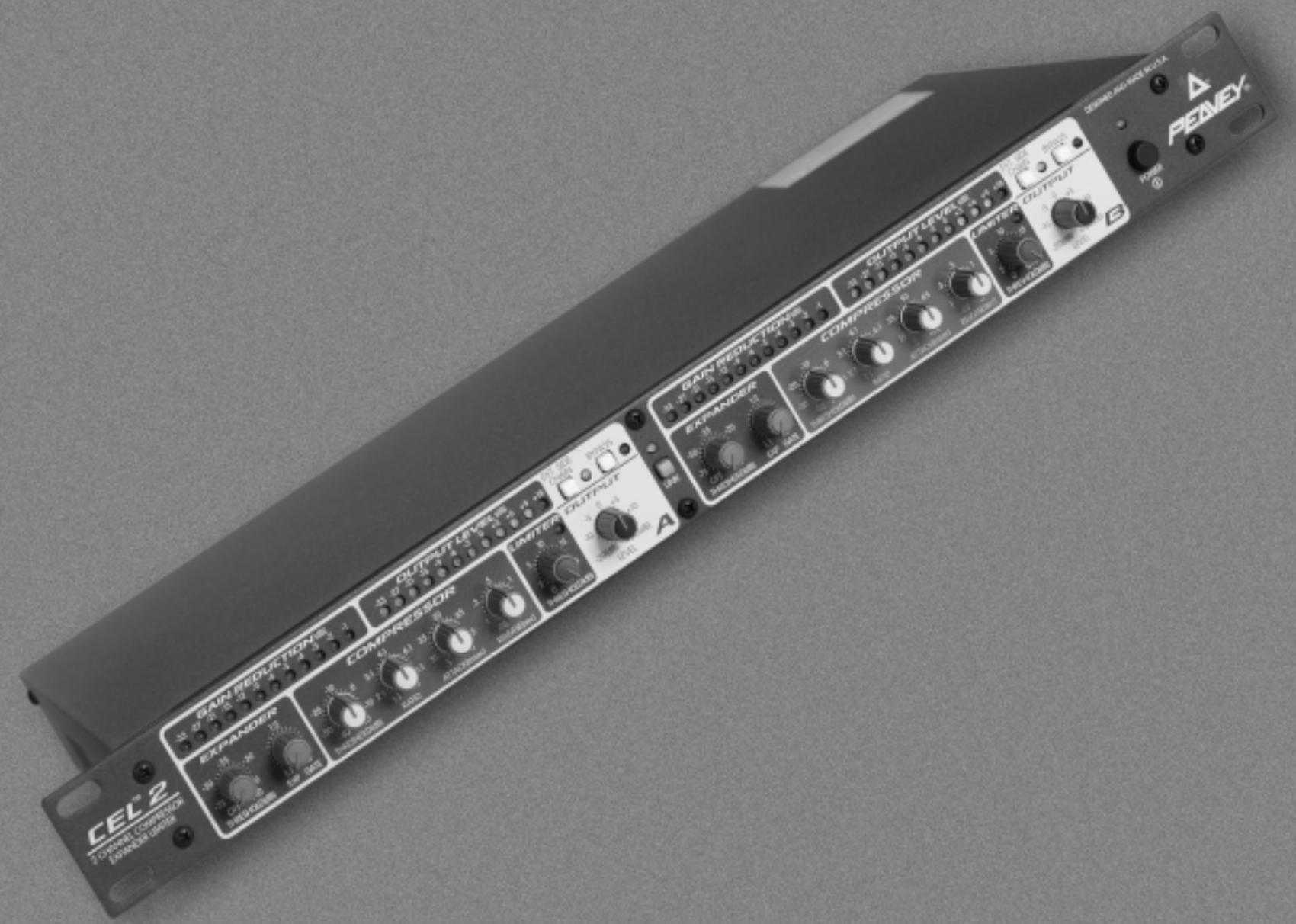
CEL 2 - Audio Compressor PEAVEY - Free user manual and instructions
Find the device manual for free CEL 2 PEAVEY in PDF.

| Product Type | Dual (stereo) audio compressor/expander/limiter |
| Brand | Peavey |
| Model | CEL 2 |
| Dimensions (W x D x H) | 483 mm x 200 mm x 44 mm (1U rack) |
| Weight | 2.5 kg estimated |
| Power supply | Mains via IEC connector, voltage depending on version (110-240 V) |
| Main functions | Compression (soft knee), expansion/gate, limiting (infinite ratio), side-chain, stereo link, mechanical bypass |
| Per-channel controls | Expander threshold, expander ratio, compressor threshold, compressor ratio, attack, release, limiter threshold, output level |
| Indicators | 2 VU meters with 12 LEDs (gain reduction and output level), power LED, side-chain LED, bypass LED, stereo link LED, limiter LED |
| Inputs/Outputs | Balanced XLR input (+4 dBu), TRS input/output (0 dBu), unbalanced Jack output, balanced XLR output, side-chain insert TRS |
| Nominal levels | XLR input: +4 dBu, Jack: 0 dBu; XLR output: +4 dBu, Jack: 0 dBu |
| Maintenance and cleaning | Unplug before cleaning. Use a soft dry cloth. Do not use solvents or abrasive products. |
| Safety | Do not open the device: risk of electric shock. No user-serviceable parts. Do not expose to rain or moisture. |
| Spare parts and repairability | Contact Peavey after-sales service or an authorized technician. Product reference CEL 2. |
| General information | Dual 1U rack compressor with VCA and RMS rectification. Soft knee action on compressor and expander. |
Frequently Asked Questions - CEL 2 PEAVEY
User questions about CEL 2 PEAVEY
0 question about this device. Answer the ones you know or ask your own.
Ask a new question about this device
Download the instructions for your Audio Compressor in PDF format for free! Find your manual CEL 2 - PEAVEY and take your electronic device back in hand. On this page are published all the documents necessary for the use of your device. CEL 2 by PEAVEY.
USER MANUAL CEL 2 PEAVEY
2 Channel Compressor Expander Limiter

Intended to alert the user to the presence of uninsulated "dangerous voltage" within the product's enclosure that may be of sufficient magnitude to constitute a risk of electric shock to persons.

Intended to alert the user of the presence of important operating and maintenance (servicing) instructions in the literature accompanying the product.
CAUTION: Risk of electrical shock — DO NOT OPEN!
CAUTION: To reduce the risk of electric shock, do not remove cover. No user serviceable parts inside. Refer servicing to qualified service personnel.
WARNING: To prevent electrical shock or fire hazard, do not expose this appliance to rain or moisture. Before using this appliance, read the operating guide for further warnings.

Thank you for purchasing the CEL™ 2 dual compressor/expander limiter. The following manual contains a detailed description, function and specification of your CEL™ 2.
The CEL™ 2 compressor is a single rack space dual compressor. It can be operated either as two independent compressors, or as a syncsed stereo compressor with true RMS summing. High quality voltage controlled amplifier (VCA) and RMS-rectifier integrated circuits are used to maintain low distortion and excellent noise performance.
A soft knee topology is used for each function to provide smooth transition curves. (When the circuits become active, the gain change is phased in rather than instantaneously applied.) This causes compression and limiting to be less obvious and more pleasing to the ear, as well as being easier to adjust for the desired result.
The downward expander section has threshold and ratio adjustments to allow it to be used for noise reduction (slight ratio) or a gate (high ratio). The compressor has attack and release controls in addition to threshold and ratio controls for complete versatility. Any level lost due to compression can be made up by the output level control.
The limiter is an infinite ratio compressor that keeps the output from exceeding a level set by its threshold control and has only one adjustment. It is totally independent of the compressor's settings and can be used to stop peaks from getting through when only mild compression (low ratio) is desired. It has its own LED (with a half-second peak hold time) to indicate when it has been activated.
Each section (expander, compressor or limiter) can be set so that it is disabled either by a threshold or ratio adjustment.
A side-chain insert in the detector path allows manipulation of the detector signal. The control signal can be frequency shaped or replaced for de-essing, or ducking purposes. It is engaged by a front panel switch. If this switch is pressed with nothing connected to the rear panel side-chain TRS jack, the signal from the opposite channel is fed to the detector, and the compressor ducks when there is signal on the other channel without the need for cross patching (the compressor controls will set how it functions). If an external equalizer is inserted into the path, normal side-chain functions (de-essing, rumble filtering, etc.) can be accomplished.
A dual-mono/stereo link switch sums the RMS detected levels of each channel together to accurately represent the stereo signal's amplitude. This amplitude voltage is used to control both VCAs. In this mode, only the controls associated with channel A function. The gain reduction LED array of channel B is turned off to give a visual clue as to which knobs are operational.
There are two twelve segment LED arrays that show the output level and the amount of gain reduction. By watching the gain reduction meter, the action of an adjustment is readily apparent and easy to set. The output level can be set to achieve the best signal to noise ratio.
A hard-wired bypass switch disengages all functions and operates even when the unit is not powered.
FRONT PANEL
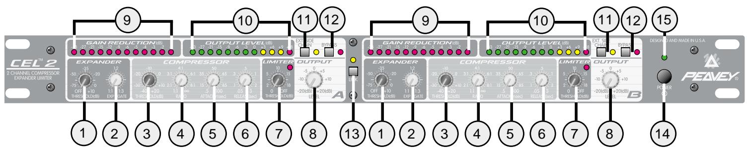
CONTROL FUNCTIONS:
(1) EXPANDER THRESHOLD: Sets the level at which the downward expander begins operation. (If it is set at the minimum position, the threshold is so low that the expander never activates, effectively disabling it.) If the input signal drops below the threshold's set point, the expander fades it out according to the slope (ratio) set by the expander RATIO control. The soft knee design smoothes the transition from off to active by dynamically shifting the slope through the transition point. The attack and release times are preset for fast action.
(2) EXPANDER RATIO: The expander ratio is determined by dividing the input level by the output level. A ratio of 1:3 signifies that the output level has dropped three times as fast as the input. A ratio of 1:1.1 has such a slight slope that it is barely audible. Ratios of 1:1.2 to 1:2 are typically used to eliminate background noise and to dampen room reverberations. Higher ratios are used when gating is required.
(3) COMPRESSOR THRESHOLD: Sets the point that compression action begins. Any signal above this threshold will be compressed at the amount set by the compressor ratio control. If it drops below this point, the compressor has no effect. At the maximum setting, the compressor will be out of circuit for all signals except very high peaks. At the minimum setting, the source will be almost continuously compressed.
(4) COMPRESSOR RATIO: Varies the amount of compression. It is the ratio of the input level to the output level. A ratio of 4:1 signifies that the input level has increased four times as fast as the output (the dynamic range is compressed by a factor of four). If the ratio is 1:1 the output exactly tracks the input, and there is no compression. Ratios of 2:1 to 4:1 are typically used for vocals and musical instruments. Higher ratios provide a soft limiting function, since the compressor uses the same soft knee design as is used in the expander (see #1).
(5) COMPRESSOR ATTACK: Sets the speed at which the compressor circuit responds to an increase in the input level. Minimum settings allow it to act quickly so that fast transients do not get through. High settings slow down the response time to let the signal settle before acting upon it. (Useful for those situations when you want percussive attacks, but still need compression.)
(6) COMPRESSOR RELEASE: Sets the time which the compressor circuit takes to track the input after a drop in level. Low settings will cause the compressor to follow the signal closely, so that rapid input changes will not be lost during compression. Higher settings will cause the compressor to disengage more gradually, which helps reduce pumping and breathing.
(7) LIMITER THRESHOLD: The limiter is an infinite ratio compressor. The threshold control defines the point that absolute limiting begins. The limit LED will light and hold for half a second (to make transients visible) when this threshold has been exceeded. To disable limiting, set this control to maximum.
(8) OUTPUT LEVEL: Adjusts the post-processing gain to make up for compression loss. It does not adjust the input level. The input levels should be set by the source equipment to 0 dBu (1/4" jacks) or +4 dBu (XLR jacks) for best noise performance. The output level is monitored by an LED meter to give a visual indication of signal strength.
(9) GAIN REDUCTION METER: A twelve segment LED array that tells how much gain reduction is being applied to the signal. If this meter is not active, there is no change to the input signal. It is very useful for making adjustments, since the action of all controls is easily seen.
(10) OUTPUT LEVEL METER: This is a peak indicating meter that is connected to the output jack. The 0 dB point is 0 dBu for the 1/4'' jacks and +4 dBu for the XLR jacks.
(11) EXTERNAL SIDE CHAIN ENABLE: The side chain is actually an alternate loop inserted into the detector path. This switch enables external processing. Frequency shaping can be applied for de-essing (add a 2 kHz to 6 kHz bandpass filter) and rumble removal (add a 40 Hz to 120 Hz cut). If there is nothing plugged into the side chain jack at the back of the unit, it connects the opposite channel's signal to the detector and uses it for control, making this channel reduce amplitude (or duck) when a signal is present on the other channel. Adjust the compressor controls for the desired amount of action. When the side chain is active the LED will illuminate.
(12) BYPASS: This is a hard wired bypass switch that connects the input jack directly to the output jack (same type only). The 1/4'' jacks are connected together and the XLR jacks are connected together. Bypass will not function for 1/4'' input to XLR output or XLR input to 1/4'' output. When the bypass is enabled the LED will illuminate.
(13) STEREO LINK: If the compressor is to be used with stereo signals, the link switch should be pressed. It sums the RMS detector voltages together for an accurate representation of the two levels, and locks the channels together to maintain the stereo image during compression. When the link switch is pressed, all of channel A's controls except the output level affect both channels. The controls for channel B are disabled except its output level. As a reminder of this, the gain reduction meter for channel B is disconnected. The gain reduction meter for channel A is accurate for both channels and should be used to monitor VCA activity. When the stereo link is enabled the LED will illuminate
(14) POWER SWITCH: Power is applied when this switch is pressed. As with all devices, the power to external devices should be applied first, then the mixer and finally the power amp to minimize turn on transients.
(15) POWER LED Indicates that AC mains power is connected and power switch is in the on position.
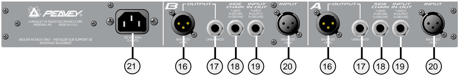
INPUT AND OUTPUT JACKS:
(16) BALANCED OUTPUT: XLR servo balanced output. The nominal level (when the output meter is at 0 dB) is +4 dBu. (Pin 2 is positive in phase).
(17) UNBALANCED OUTPUT: 14 unbalanced output. If this jack is used, the input/output TRS jack (#18) becomes an input only (tip) jack. The nominal level is 0 dBu.
(18) DETECTOR SIDE CHAIN INSERT: 1 / 4" stereo (TRS) jack which allows an external device (such as a graphic EQ) to be inserted into the detector's signal path. The tip has the send signal, the ring is the return input. A switch in the jack normally connects the return (ring) to the other channel's send (tip) until a plug is inserted. This gives ducking capabilities without patching.
(19) INPUT/OUTPUT: A dual function 14 TRS jack that has both input and output signals configured so that a standard (not cross wired) stereo shielded cable can be used to plug into the TRS insert of a mixer. (The tip is the compressor input, the ring is the output, which match the insert jack wiring of all current Peavey mixers.) If the unbalanced output jack (#17) is used, the ring connection (output) of this jack is disconnected, and it becomes an input only jack (tip). The nominal levels are 0 dBu.
(20) BALANCED INPUT: XLR balanced input for +4 dBu (nominal) line level inputs. Pin 2 is the positive phase, pin 3 is the negative phase.
(21) A/C POWER INLET: This is the receptacle for an IEC line cord, which provides AC power to the CEL™ 2. Connect the line cord to this connector to provide power to the unit. Damage to the equipment may result if improper line voltage is used (see line voltage marking on unit).
NOTE: FOR UK ONLY
As the colors of the wires in the mains lead of this apparatus may not correspond with the colored markings identifying the terminals in your plug, proceed as follows: (1) The wire which is colored green and yellow must be connected to the terminal which is marked by the letter E or by the earth symbol or colored green or green and yellow. (2) The wire which is colored blue must be connected to the terminal which is marked with the letter N or the color black. (3) The wire which is colored brown must be connected to the terminal which is marked with the letter L or color red.
CONTROL SETTING PROCEDURES
If you are starting from scratch, or have gotten something out of whack and do not know exactly what to adjust, begin by setting the controls so that all functions are disabled. Here are the control positions for this:
| EX THRESH: | min (off) |
| EX RATIO: | min (1.1:1) |
| COMP THRESH: | max (+20dB) |
| COMP RATIO: | min (1:1) |
| ATTACK: | center (50msec) |
| RELEASE: | center (.5 sec) |
| LIMIT: | max (off) |
| OUTPUT: | center (0dB) |
Naturally, the controls that need to be adjusted will depend on what you want accomplished. Here are some suggestions to get you up and running - just follow the order listed, and leave the controls in the above (disabled) positions if that particular function is not required.
- Determine the maximum output level and adjust the limit threshold so that at the loudest peaks the output level never exceeds this point. (The action of the limiter can be seen on the GAIN REDUCTION METER. If it never activates, there will be no LED activity.) One way to do this is to deliberately increase the input to the compressor until the desired maximum level is exceeded, then turn the limit threshold control CCW until it limits it to the correct level. Reset the input level until the peaks just barely light the gain reduction meter. An alternate method is to turn down the limit threshold until gain reduction has just occurred, then adjust the output level control to set the desired output level.
- To set up a noise gate, first turn the EXPANDER RATIO control fully CW. During quiet passages of the source (between songs, when the mics are not being used, etc.) adjust the EXPANDER THRESHOLD CW until gain reduction is indicated (a reduction of -12 dB is a good starting point). Re-adjust the EXPANDER RATIO to set the desired gating action when the source changes from noise to signal. A setting of 1.1:1 has little action and can tolerate higher threshold settings without coloring the sound, 3:1 will cause an abrupt turn on and off when the signal changes and will probably need a lower threshold setting to prevent the signal from dropping off when you don't want it to. You may have to go back and adjust the threshold after the ratio has been changed, since the soft knee circuitry has more effect at lower ratios, making the transition point less obvious.
- For typical vocal compression, set the COMPRESSOR RATIO control to 4:1 (a range of 2:1 to 6:1 is common) and adjust the COMPRESSOR THRESHOLD until the desired amount of gain reduction is seen on the meter. This is a personal preference, but continuous gain reduction greater than 9 dB (especially with higher ratios) could be excessive and could create pumping and breathing artifacts as the signal rises and falls. Lower ratios will have a more gentle effect. Adjust the ATTACK control to low values to suppress leading edge spikes, or to high values to let them through (often used to pass through the click of a drum hit). The RELEASE control is adjusted to smooth the transition as it comes out of compression. Too quick a release will cause the signal to sound artificial. A fast attack and a short release time will cause the compressor to track the signal very closely (and keep the dynamic range very
limited), but can severely impact the sound. (A 50 millisecond attack, and .5 second release time are good starting points.)
- After all the settings are made, adjust the OUTPUT LEVEL control for a 0 dB average on the output meter. This control can also be used to change levels to match various inputs (+4 dBu, 0 dBu, or -10 dBV) to maintain proper headroom levels. (0dB corresponds to 0 dBu at the 1/4" jacks and +4 dBu at the XLR jacks)
CEL™ 2 SPECIFICATIONS
| CONTROL | ADJUSTMENT RANGE |
| Expander Threshold | -80dBu to +10dBu |
| Expander Ratio | 1:1.1 to 1:3 (gate) |
| Expander Attack | .5 msec (fixed) |
| Expander Release | 50 msec (fixed) |
| Compressor Threshold | -40dBu to +20dBu |
| Compressor Ratio | 1:1.1 (off) to infinite: 1 (limit) |
| Compressor Attack | .5 msec to 3 sec |
| Compressor Release | .05 sec to 3 sec |
| Limiter Threshold | 0dBu to +20dBu (off) |
| Limiter Attack | .5 msec (fixed) |
| Limiter Release | 50 msec (fixed) |
| Output Level | -20 dB to +20 dB |
| INPUT | IMPEDANCE | CONNECTOR |
| XLR (balanced) | 30k ohms | XLR Pin 1 = ground Pin 2 = positive phase Pin 3 = negative phase |
| 1/4" Phone (unbalanced) In-Out | 10k ohms | 1/4" phone tip = input ring = output (see control functions above) |
THD: .01% 20 Hz to 20 Hz (10 Hz to 80 kHz BW)
SIGNAL TO NOISE: 97 dB (+4 dBu reference level)
FREQUENCY RESPONSE: 20 Hz to 64 kHz +0 dB/-1 dB
OUTPUT IMPEDANCE: 100 ohms (XLR and 1/4")
METERS: Four 12 segment LED arrays, two peak LEDs
DIMENSIONS:
19" W x 9" D x 1.75" H
(48.26 cm x 22.9 cm x 4.44 cm)
WEIGHT: 7.3 lb (3.31 kg)
POWER REQUIREMENTS:
DOM: 120 V AC 60 Hz 15 Watts Nominal
EXP: 230 V AC 50/60 Hz 15 Watts Nominal
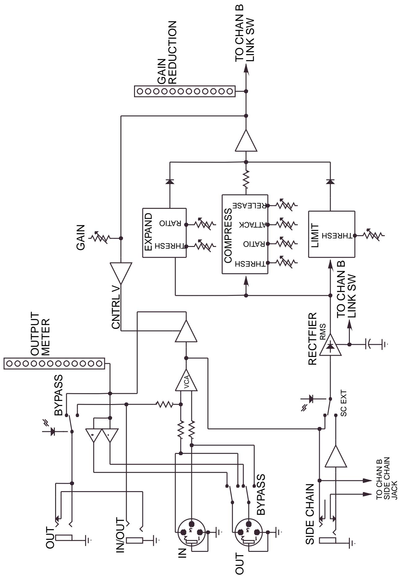
CEL™ 2 COMPRESSOR BLOCK DIAGRAM
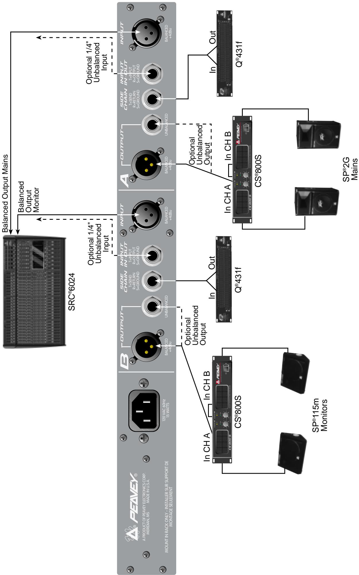
CEL™ 2 Hookup Diagram
Effective Date: July 1, 1998
What This Warranty Covers
Your Peavey Warranty covers defects in material and workmanship in Peavey products purchased and serviced in the U.S.A. and Canada.
What This Warranty Does Not Cover
The Warranty does not cover: (1) damage caused by accident, misuse, abuse, improper installation or operation, rental, product modification or neglect; (2) damage occurring during shipment; (3) damage caused by repair or service performed by persons not authorized by Peavey; (4) products on which the serial number has been altered, defaced or removed; (5) products not purchased from an Authorized Peavey Dealer.
Who This Warranty Protects
This Warranty protects only the original retail purchaser of the product.
How Long This Warranty Lasts
The Warranty begins on the date of purchase by the original retail purchaser. The duration of the Warranty is as follows:
| Product Category | Duration |
| Guitars/Basses, Amplifiers, Pre-Amplifiers, Mixers, Electronic Crossovers and Equalizers | 2 years * (+ 3 years) |
| Drums | 2 years * (+ 1 year) |
| Enclosures | 3 years * (+ 2 years) |
| Digital Effect Devices and Keyboard and MIDI Controllers | 1 year * (+ 1 year) |
| Microphones | 2 years |
| Speaker Components (incl. speakers, baskets, drivers, diaphragm replacement kits and passive crossovers) and all Accessories | 1 year |
| Tubes and Meters | 90 days |
[denotes additional warranty period applicable if optional Warranty Registration Card is completed and returned to Peavey by original retail purchaser within 90 days of purchase.]
What Peavey Will Do
We will repair or replace (at Peavey's discretion) products covered by warranty at no charge for labor or materials. If the product or component must be shipped to Peavey for warranty service, the consumer must pay initial shipping charges. If the repairs are covered by warranty, Peavey will pay the return shipping charges.
How To Get Warranty Service
(1) Take the defective item and your sales receipt or other proof of date of purchase to your Authorized Peavey Dealer or Authorized Peavey Service Center.
OR
(2) Ship the defective item, prepaid, to Peavey Electronics Corporation, International Service Center, 412 Highway 11 & 80 East, Meridian, MS 39301 or Peavey Canada Ltd., 95 Shields Court, Markham, Ontario, Canada L3R 9T5. Include a detailed description of the problem, together with a copy of your sales receipt or other proof of date of purchase as evidence of warranty coverage. Also provide a complete return address.
Limitation of Implied Warranties
ANY IMPLIED WARRANTY, INCLUDING WARRANTYES OF MERCHANTABILITY AND FITNESS FOR A PARTICULAR PURPOSE, ARE LIMITED IN DURATION TO THE LENGTH OF THIS WARRANTY.
Some states do not allow limitations on how long an implied warranty lasts, so the above limitation may not apply to you.
Exclusions of Damages
PEAVEY'S LIABILITY FOR ANY DEFECTIVE PRODUCT IS LIMITED TO THE REPAIR OR REPLACEMENT OF THE PRODUCT, AT PEAVEY'S OPTION. IF WE ELECT TO REPLACE THE PRODUCT, THE REPLACEMENT MAY BE A RECONDITIONED UNIT. PEAVEY SHALL NOT BE LIABLE FOR DAMAGES BASED ON INCONVENIENCE, LOSS OF USE, LOST PROFITS, LOST SAVINGS, DAMAGE TO ANY OTHER EQUIPMENT OR OTHER ITEMS AT THE SITE OF USE, OR ANY OTHER DAMAGES WHETHER INCIDENTAL, CONSEQUENTIAL OR OTHERWISE, EVEN IF PEAVEY HAS BEEN ADVISED OF THE POSSIBILITY OF SUCH DAMAGES
Some states do not allow the exclusion or limitation of incidental or consequential damages, so the above limitation or exclusion may not apply to you.
This Warranty gives you specific legal rights, and you may also have other rights which vary from state to state.
If you have any questions about this warranty or service received or if you need assistance in locating an Authorized Service Center, please contact the Peavey International Service Center at (601) 483-5365 / Peavey Canada Ltd. at (905) 475-2578.
Features and specifications subject to change without notice.
IMPORTANT SAFETY INSTRUCTIONS
WARNING: When using electric products, basic cautions should always be followed, including the following:
- Read these instructions.
- Keep these instructions.
- Heed all warnings.
- Follow all instructions.
- Do not use this apparatus near water. For example, near or in a bathtub, swimming pool, sink, wet basement, etc.
- Clean only with a damp cloth.
- Do not block any of the ventilation openings. Install in accordance with manufacturer's instructions. It should not be placed flat against a wall or placed in a built-in enclosure that will impede the flow of cooling air.
- Do not install near any heat sources such as radiators, heat registers, stoves or other apparatus (including amplifiers) that produce heat.
- Do not defeat the safety purpose of the polarized or grounding-type plug. A polarized plug has two blades with one wider than the other. A grounding type plug has two blades and a third grounding plug. The wide blade or third prong is provided for your safety. When the provided plug does not fit into your inlet, consult an electrician for replacement of the obsolete outlet. Never break off the grounding write for our free booklet "Shock Hazard and Grounding". Connect only to a power supply of the type marked on the unit adjacent to the power supply cord.
- Protect the power cord from being walked on or pinched particularly at plugs, convenience receptacles, and the point they exit from the apparatus.
- Only use attachments/accessories provided by the manufacturer.
- Use only with a cart, stand, tripod, bracket, or table specified by the manufacturer, or sold with the apparatus. When a cart is used, use caution when moving the cart/apparatus combination to avoid injury from tip-over.
- Unplug this apparatus during lightning storms or when unused for long periods of time.
- Refer all servicing to qualified service personnel. Servicing is required when the apparatus has been damaged in any way, such as power-supply cord or plug is damaged, liquid has been spilled or objects have fallen into the apparatus, the apparatus has been exposed to rain or moisture, does not operate normally, or has been dropped..
- If this product is to be mounted in an equipment rack, rear support should be provided.
- Exposure to extremely high noise levels may cause a permanent hearing loss. Individuals vary considerably in susceptibility to noise induced hearing loss, but nearly everyone will lose some hearing if exposed to sufficiently intense noise for a sufficient time. The U.S. Government's Occupational and Health Administration (OSHA) has specified the following permissible noise level exposures:.
| Duration Per Day In Hours | Sound Level dBA, Slow Response |
| 8 | 90 |
| 6 | 92 |
| 4 | 95 |
| 3 | 97 |
| 2 | 100 |
| 1 1/2 | 102 |
| 1 | 105 |
| 1/2 | 110 |
| 1/4 or less | 115 |
According to OSHA, any exposure in excess of the above permissible limits could result in some hearing loss. Ear plugs or protectors to the ear canals or over the ears must be worn when operating this amplification system in order to prevent a permanent hearing loss if exposure is in excess of the limits as set forth above. To ensure against potentially dangerous exposure to high sound pressure levels, it is recommended that all persons exposed to equipment capable of producing high sound pressure levels such as this amplification system be protected by hearing protectors while this unit is in operation.
SAVE THESE INSTRUCTIONS!

PEAVEX
Features and specifications subject to change without notice.
Peavey Electronics Corporation • 711 A Street • Meridian • MS • 39301
(601) 483-5365 • FAX (601) 486-1278 • www.peavey.com