
6505 PLUS - Guitar Amplifier PEAVEY - Free user manual and instructions
Find the device manual for free 6505 PLUS PEAVEY in PDF.

| Product Type | Guitar Tube Amplifier |
| Brand | PEAVEY |
| Model | 6505 PLUS |
| Output Power | 120 W RMS (16, 8 or 4 ohms) |
| Number of Channels | 2 (Rhythm and Lead) with Crunch switch for Rhythm channel |
| Preamp Tubes | 6 x 12AX7 |
| Power Tubes | 4 x 6L6GC |
| Equalization | 3 bands (bass, mid, treble) per channel |
| Additional Controls | Presence and Resonance per channel, Bright and Crunch switch on Rhythm channel |
| Effects Loop | Yes, with footswitch |
| Preamp Output | Yes (Preamp Out) |
| Input | High impedance (470 kΩ), accepts all pickup types |
| Output Impedance | Selectable: 4, 8 or 16 ohms |
| Speaker Outputs | 2 x 1/4" jacks (parallel) |
| Footswitch Included | Yes, 3 buttons with LED, detachable 25' cable |
| Power Supply | 120 V AC, 50/60 Hz, 400 W (domestic version) |
| Dimensions | Not specified in the manual (estimated: approx. 60 x 25 x 25 cm) |
| Weight | Not specified (estimated: approx. 20 kg) |
| Maintenance and Cleaning | Use a dry cloth for cleaning; do not expose to moisture |
| Safety | Do not open, risk of electric shock; refer repairs to qualified technician |
| Spare Parts and Repairability | Tubes replaceable by a professional; bias adjustment must be performed by a qualified technician |
| General Information | Manual available in multiple languages; free download at notice-facile.com |
Frequently Asked Questions - 6505 PLUS PEAVEY
User questions about 6505 PLUS PEAVEY
0 question about this device. Answer the ones you know or ask your own.
Ask a new question about this device
Download the instructions for your Guitar Amplifier in PDF format for free! Find your manual 6505 PLUS - PEAVEY and take your electronic device back in hand. On this page are published all the documents necessary for the use of your device. 6505 PLUS by PEAVEY.
USER MANUAL 6505 PLUS PEAVEY
Intended to alert the user to the presence of uninsulated "dangerous voltage" within the product's enclosure that may be of sufficient magnitude to constitute a risk of electric shock to persons.
Intended to alert the user of the presence of important operating and maintenance (servicing) instructions in the literature accompanying the product.
CAUTION: Risk of electrical shock — DO NOT OPEN!
CAUTION: To reduce the risk of electric shock, do not remove cover. No user serviceable parts inside. Refer servicing to qualified service personnel.
WARNING: To prevent electrical shock or fire hazard, this apparatus should not be exposed to rain or moisture, and objects filled with liquids, such as vases, should not be placed on this apparatus. Before using this apparatus, read the operating guide for further warnings.

WARNING: When using electrical products, basic cautions should always be followed, including the following:
- Read these instructions.
- Keep these instructions.
- Heed all warnings.
- Follow all instructions.
- Do not use this apparatus near water.
- Clean only with a dry cloth.
- Do not block any of the ventilation openings. Install in accordance with manufacturer's instructions.
- Do not install near any heat sources such as radiators, heat registers, stoves or other apparatus (including amplifiers) that produce heat.
- Do not defeat the safety purpose of the polarized or grounding-type plug. A polarized plug has two blades with one wider than the other. A grounding type plug has two blades and a third grounding plug. The wide blade or third prong is provided for your safety. If the provided plug does not fit into your outlet, consult an electrician for replacement of the obsolete outlet.
- Protect the power cord from being walked on or pinched, particularly at plugs, convenience receptacles, and the point they exit from the apparatus.
- Only use attachments/accessories provided by the manufacturer.
- Use only with a cart, stand, tripod, bracket, or table specified by the manufacturer, or sold with the apparatus. When a cart is used, use caution when moving the cart/apparatus combination to avoid injury from tip-over.
- Unplug this apparatus during lightning storms or when unused for long periods of time.
- Refer all servicing to qualified service personnel. Servicing is required when the apparatus has been damaged in any way, such as power-supply cord or plug is damaged, liquid has been spilled or objects have fallen into the apparatus, the apparatus has been exposed to rain or moisture, does not operate normally, or has been dropped.
- Never break off the ground pin. Write for our free booklet "Shock Hazard and Grounding." Connect only to a power supply of the type marked on the unit adjacent to the power supply cord.
- If this product is to be mounted in an equipment rack, rear support should be provided.
- Note for UK only: If the colors of the wires in the mains lead of this unit do not correspond with the terminals in your plug, proceed as follows:
a) The wire that is colored green and yellow must be connected to the terminal that is marked by the letter E, the earth symbol, colored green or colored green and yellow.
b) The wire that is colored blue must be connected to the terminal that is marked with the letter N or the color black.
c) The wire that is colored brown must be connected to the terminal that is marked with the letter L or the color red.
- This electrical apparatus should not be exposed to dripping or splashing and care should be taken not to place objects containing liquids, such as vases, upon the apparatus.
- Exposure to extremely high noise levels may cause a permanent hearing loss. Individuals vary considerably in susceptibility to noise-induced hearing loss, but nearly everyone will lose some hearing if exposed to sufficiently intense noise for a sufficient time. The U.S. Government's Occupational Safety and Health Administration (OSHA) has specified the following permissible noise level exposures:
| Duration Per Day In Hours | Sound Level dBA, Slow Response |
| 8 | 90 |
| 6 | 92 |
| 4 | 95 |
| 3 | 97 |
| 2 | 100 |
| 1 1/2 | 102 |
| 1 | 105 |
| 1/2 | 110 |
| 1/4 or less | 115 |
According to OSHA, any exposure in excess of the above permissible limits could result in some hearing loss. Ear plugs or protectors to the ear canals or over the ears must be worn when operating this amplification system in order to prevent a permanent hearing loss, if exposure is in excess of the limits as set forth above. To ensure against potentially dangerous exposure to high sound pressure levels, it is recommended that all persons exposed to equipment capable of producing high sound pressure levels such as this amplification system be protected by hearing protectors while this unit is in operation.
SAVE THESE INSTRUCTIONS!
Tube Guitar Amplifier
Congratulations on your purchase of the 6505+. Like the 6505 head, the 6505+ offers two channels. However, the 6505+ adds separate EQ, Resonance, and Presence controls to each channel, giving you more control and flexibility. The new footswitch provides foot control of channel selection, effects loop, and the newly added ability to select the Crunch feature. Now you can instantly obtain that extra gain in the Rhythm Channel with your foot and never have to take your hand off the guitar. Finally, the Clean Channel has been added, completely redesigned to sound much cleaner, and has one 12AX7 devoted to just the Clean/Crunch.
The following guide explains these features and how to operate each one in order to obtain your desired sound. We recommend that you read this manual carefully, paying close attention to any warnings or cautions.
FEATURES:
- Two distinct tube channels with footswitch control
- LED "active" indicators for each channel
- Bright switch for Rhythm channel
- Crunch switch on Rhythm channel with footswitch control
- Separate equalizer sections for each channel
- Separate power amp controls (Resonance and Presence) for each channel
- Separate preamp controls (Pre and Post Gain) for each channel
- Standby power switch
- Bias test points on rear panel
- Effects loop with footswitch control
- 1 / 4 " Preamp output jack
- Speaker impedance selection switch (4, 8, 16 ohm)
- Two parallel 1 / 4'' speaker output jacks
- 120 watts output power
- Metal three button footswitch with detachable 25' cable


POWER
1. LINE CORD
This line cord provides the AC power to the unit. Connect the line cord to a properly grounded AC supply. Damage to the equipment may occur if improper line voltage is used. (See voltage marking on unit.) Never remove or cut the ground pin of the line cord plug.
NOTE: FOR UK ONLY
As the colors of the wires in the mains lead of this apparatus may not correspond with the colored markings identifying the terminals in your plug, proceed as follows: (1) The wire which is colored green and yellow must be connected to the terminal which is marked by the letter E, or by the earth symbol, or colored green or green and yellow. (2) The wire which is colored blue must be connected to the terminal which is marked with the letter N, or the color black. (3) The wire which is colored brown must be connected to the terminal which is marked with the letter L or the color red.
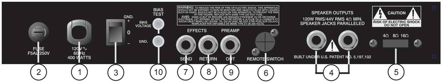
2. FUSE
WARNING: THE FUSE SHOULD ONLY BE REPLACED WHEN THE POWER CORD HAS BEEN DISCONNECTED FROM ITS POWER SOURCE. A 5 amp fuse is located within the cap of the fuse holder. It must be replaced with the same type and value in order to avoid damage to the equipment and to prevent voiding the warranty. If the amp repeatedly blows fuses, it should be taken to a qualified service center for repair.
3. GROUND SWITCH
This is a three-position, rocker type switch which, for most applications, should be operated in the center (zero) position. If hum or noise is noticed coming from the speaker enclosure(s) with the Ground Switch in the center position, place the Ground Switch to positive (+) or negative (-) to minimize hum. Should a hum/ noise problem continue, consult your authorized Peavey dealer, the Peavey factory, or a qualified service technician.
NOTE: THE GROUND SWITCH IS NOT FUNCTIONAL ON 220/240 VOLT MODELS.
INS AND OUTs
4. SPEAKER JACKS
These jacks are provided for the connection of speaker enclosure(s). The minimum speaker impedance is 4 ohms. The Impedance Selector Switch (5) should be set accordingly.
5. IMPEDANCE SELECTOR SWITCH
Use this switch to select the appropriate impedance of the speaker enclosure(s) connected to the Speaker Jacks (4). If two enclosures of equal impedance are used, the switch should be set at one half of that value (e.g., two 16 ohm enclosures: set switch to 8 ohms; two 8 ohm enclosures: set switch to 4 ohms).
6. REMOTE FOOTSWITCH JACK
This jack is provided for the connection of the supplied remote footswitch. The footswitch cable should be plugged in before the amp is powered up. When the footswitch is plugged into the Remote Footswitch Jack, the Channel Select switch (14) must be pressed to the "in" position for remote selection of the Lead or Rhythm channel (right footswitch button). The On and Off operation of Effects (left footswitch button) will work at all times. Remote selection of Crunch gain boost (center footswitch button) is available only when the Crunch Switch (22) is selected. See page 9 for detailed Footswitch diagram.
7/8.EFFECTSSEND/EFFECTSRETURN
Signals are supplied to outboard effects or signal processing units by patching from the Effects Send (7) output into the outboard unit(s) and back into the Effects Return (8) input using shielded cables with 1/4 " mono phone plugs. Only non-gain effects devices (chorus, reverb, delay, etc.) should be used in the effects loop. If footswitch is used, "Effects" must be selected (LED illuminated) for effects to work.
9. PREAMP OUT
This output can be used to send a preamp signal from the 6505TM+ to a mixing console, tape recorder, etc., using a shielded instrument cable. Patching from the PREAMP OUT does not affect the normal operation of the amplifier.
BIAS ADJUST SYSTEM
10. BIAS TEST TERMINALS
These terminals, along with the adjustment knob behind the grille are provided to measure and adjust the power amp tubes' bias. The bias adjustment should only be done by a qualified technician.
FRONT PANEL FEATURES
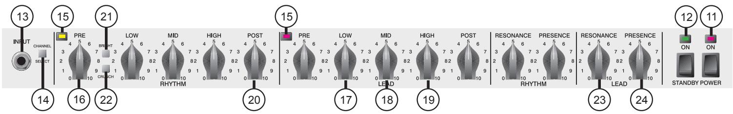
ON STANDBY
11. POWER SWITCH/LED
This switch supplies power to the unit. Depressed to the "ON" position, the red Power LED indicator will illuminate above the Power Switch when power is being supplied to the unit.
12. STANDBY SWITCH/LED
This switch allows the 6505+ to be placed in a non-operational standby mode. When the Standby Switch is activated, the tubes remain hot and ready for instantaneous operation, eliminating warm-up time. The Standby LED indicator above the switch will illuminate when the amp is in the operational mode.
PREAMP
13. INPUT
The 6505+ input jack is designed to accommodate a variety of guitar output levels, regardless of pickup configuration. Due to the extreme high gain capabilities of the 6505+ , it is imperative that you use a premium shielded instrument cable in order to minimize noise.
14. CHANNEL SELECT SWITCH
This switch allows selection of the Rhythm or Lead Channel. Depressing the switch to the "in" position activates the Lead Channel. The red LED next to the Lead Pre control will illuminate to indicate that the Lead Channel is active. In the "out" position, the Rhythm channel is activated and the green LED illuminates next to the Rhythm Pre control to indicate that the Rhythm Channel is active. Channels may be selected using the remote footswitch. If remote selection is desired, the Channel Select Switch must be set to the "in" position (Lead Channel). See page 11.
15. CHANNEL SELECT LED
Both the Rhythm Channel and Lead Channel have these LEDs to indicate which channel is active. The two Channel Select LEDs are never on at the same time. The channel with its indicator illuminated is the active channel.
16/20. PRE and POST GAIN
The channel Pre (16) and Post (20) Gain controls operate in the same manner for both channels. However, the Lead channel does have more pregain than the Rhythm Channel. In most applications, the Rhythm channel should be set up with the Pre Gain at the lower "cleaner" settings (o-4) and the Post Gain should be set for overall volume. The Rhythm channel can be converted to a medium distortion channel by activating the Crunch switch (22). This will more closely match the pre gain of the two channels. The Lead channel should be set up with the Pre Gain at the mid to upper settings (5-10) and the Post Gain should be set for overall volume.
17/18/19. EQUALIZATION
The 6505+ 's equalization block features passive low, mid, and high EQ that is custom tailored for each channel. Adjusting the control(s) counterclockwise will result in an attenuation of the signal within the frequency band.
21. BRIGHT SWITCH
Activates a preset boost in the treble frequencies (6 dB at 2 kHz) and affects only the Rhythm Channel.
22. CRUNCH SELECT SWITCH
Boosts the gain of the Rhythm channel to create a medium distortion or in between tone. Depress to the "in" position to activate.
23/24. RESONANCE / PRESENCE
Unique to Peavey instrument amplifiers, the Resonance control (23) can be set to boost the gain of the power amp in the low frequencies at the resonance/attenuation point of the speaker cabinet. In simple terms, the Resonance control works like a low EQ to offset low-end frequency drop out. The Presence control (24) works in the same manner, boosting the high frequencies. Experimentation using your particular speaker cabinet, along with personal taste, will determine your setting for these important controls.
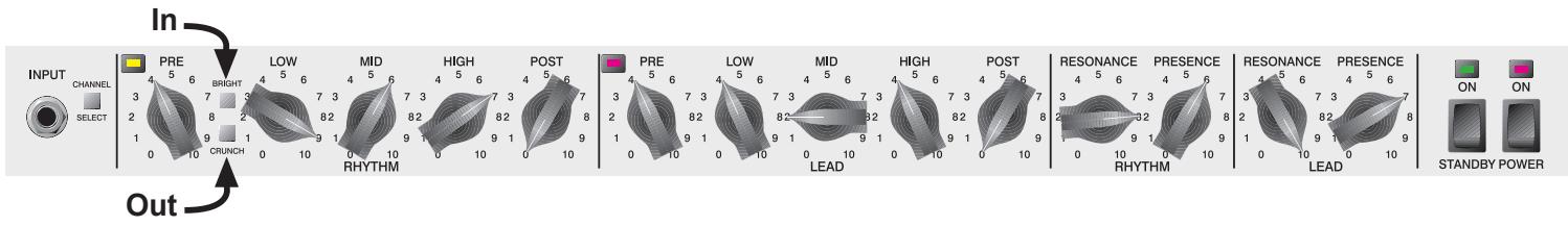
6505™+
RECOMMENDED SETTINGS
Southern Rock/Country

HP's Signature Setting
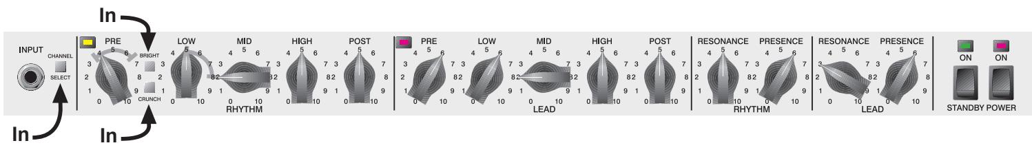
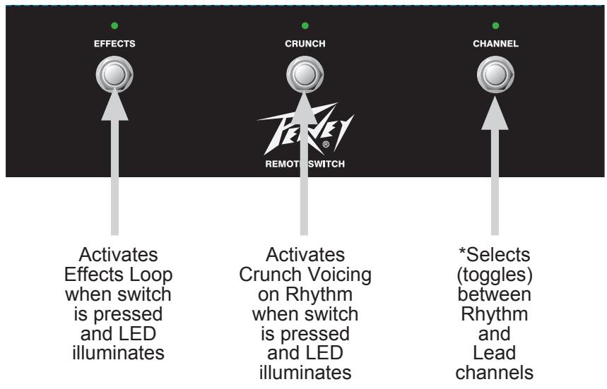
All switches are push on/push off.
There are no momentary switches on the footswitch.
*NOTE:
Channel select switch (14) must be pressed
to the "in" position for this switch to function.
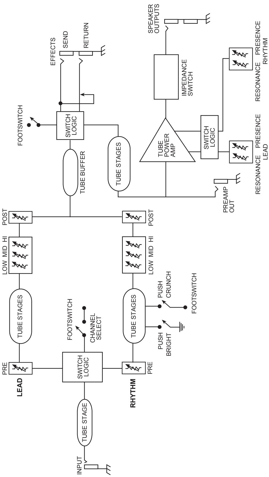
6505 TM+
BLOCK DIAGRAM
6505 TM +
SPECIFICATIONS
POWER AMPLIFICATION SECTION
RATED POWER AND LOAD:
120 W RMS into 16, 8, or 4 ohms
POWER @ CLIPPING:
(Typically @ 5% THD, 1 kHz, 120 V AC line)
130 W RMS into 16, 8, or 4 ohms
(Bias must be reduced to measure.)
FREQUENCY RESPONSE:
+0, -3 dB, 50 Hz to 20 kHz @ 100 W
RMS into 8 ohms
HUM AND NOISE:
Greater than 75 dB below rated power
POWER AMP EQ:
Active Presence: +10 dB @ 2 kHz
Active Resonance: +10 dB @ cabinet
resonant frequency
POWER CONSUMPTION (Domestic):
400 watts 50/60 Hz, 120 V AC
(Domestic)
TUBE COMPLEMENT:
6-12AX7 preamp tubes
(1 for clean/crunch, 3 for Lead, 1 for
EFX and 1 phase splitter
4-6L6GC
PREAMP SECTION
The following specs are measured @
1 kHz with the controls preset as follows:
Low and High EQ @ 10
Mid EQ @ 0
Bright out
Lead and Rhythm Posts @ 10
Presence and Resonance @ 0 dB
Nominal levels with Pre Gains @ 5
Minimum levels with Pre Gains @ 10
PREAMP INPUT:
Impedance: Very high Z, 470K ohms
Lead Channel (with channel select in):
Nominal Input Level: -60 dBV,
1 mV RMS
Minimum Input Level: -76 dBV,
.15 mV RMS
Clean Channel (with channel select out):
Nominal Input Level: -30 dBV,
30 mV RMS
Minimum Input Level: -34 dBV,
20 mV RMS
Maximum Input Level: 0 dBV,
1.0 VRMS
(Subtract 24 dB with Crunch switch in.)
EFFECTS SEND:
Load Impedance: 47 k ohms or greater
Nominal Output: -10 dBV, 300 mV RMS
EFFECTS RETURN:
Impedance: Very High Z, 470 k ohms
Designed Level: -10 dBV, 300 mV RMS
PREAMP OUT:
Load Impedance: 47 k ohms or greater
Nominal Output: +10 dBV, 3 V RMS
REMOTE FOOTSWITCH:
Special 3-button unit with LED indicators
(supplied)
Channel select and reverb
SYSTEM HUM AND NOISE @
NOMINAL LEVEL (clean channel):
(20 Hz to 20 kHz unweighted)
Greater than 63 dB below rated power
EQUALIZATION:
Custom Low, Mid, and High passive type EQ
Push Bright (Rhythm Channel only)
+6 dB @ 2 kHz
Push Crunch (Rhythm Channel only)
Increases gain
DIMENSIONS (H x W x D):
10'' × 26.625'' × 11.75''
(25.4 cm × 67.6 cm × 29.8 cm
WEIGHT:
48.3 lbs. (21.91 kg)
DEUTSCH
6505TM+
The 6505+ input jack is designed to accommodate a variety of guitar output levels, regardless of pickup configuration. Due to the extreme high gain capabilities of the 6505+ , it is imperative that you use a premium shielded instrument cable in order to minimize noise.
Southern Rock/Country
(Standard @ 5% THD, 1 kHz, 120 V AC)
Résonance Active: +10 dB @ la
Postes LEAD & RHYTHM @ 10
DIMENSIONS (H x L x P):
10'' × 26.625'' × 11.75''
(25.4 cm x 67.6 cm x 29.8 cm
POIDS:
48.3 lbs. (21.91 kg)
ESPANOL
6505TM+
Southern Rock/Country

400 vati0s 50/60 Hz, 120 V AC
(Doméstico)
COMPLEMENTO DE VALVULAS:
6-12AX7 Valvulas de previo
NIVEL NOMINAL (canal clean):
DIMENSIONES (A x A x P):
10'' × 26.625'' × 11.75''
(25.4 cm x 67.6 cm x 29.8 cm
PESO:
48.3 lbs. (21.91 kg)
What This Warranty Covers
Your Peavey Warranty covers defects in material and workmanship in Peavey products purchased and serviced in the U.S.A. and Canada.
What This Warranty Does Not Cover
The Warranty does not cover: (1) damage caused by accident, misuse, abuse, improper installation or operation, rental, product modification or neglect; (2) damage occurring during shipment; (3) damage caused by repair or service performed by persons not authorized by Peavey; (4) products on which the serial number has been altered, defaced or removed; (5) products not purchased from an Authorized Peavey Dealer.
Who This Warranty Protects
This Warranty protects only the original retail purchaser of the product.
How Long This Warranty Lasts
The Warranty begins on the date of purchase by the original retail purchaser. The duration of the Warranty is as follows:
| Product Category | Duration |
| Guitars/Basses, Amplifiers, Pre-Amplifiers, Mixers, Electronic Crossovers and Equalizers | 2 years * (+ 3 years) |
| Drums | 2 years * (+ 1 year) |
| Enclosures | 3 years * (+ 2 years) |
| Digital Effect Devices and Keyboard and MIDI Controllers | 1 year * (+ 1 year) |
| Microphones | 2 years |
| Speaker Components (incl. speakers, baskets, drivers, diaphragm replacement kits and passive crossovers) and all Accessories | 1 year |
| Tubes and Meters | 90 days |
[Denotes additional warranty period applicable if optional Warranty Registration Card is completed and returned to Peavey by original retail purchaser within 90 days of purchase.]
What Peavey Will Do
We will repair or replace (at Peavey's discretion) products covered by warranty at no charge for labor or materials. If the product or component must be shipped to Peavey for warranty service, the consumer must pay initial shipping charges. If the repairs are covered by warranty, Peavey will pay the return shipping charges.
How To Get Warranty Service
(1) Take the defective item and your sales receipt or other proof of date of purchase to your Authorized Peavey Dealer or Authorized Peavey Service Center. OR
(2) Ship the defective item, prepaid, to Peavey Electronics Corporation, International Service Center, 412 Highway 11 & 80 East, Meridian, MS 39301 or Peavey Canada Ltd., 95 Shields Court, Markham, Ontario, Canada L3R 9T5. Include a detailed description of the problem, together with a copy of your sales receipt or other proof of date of purchase as evidence of warranty coverage. Also provide a complete return address.
Limitation of Implied Warranties
ANY IMPLIED WARRANTY, INCLUDING WARRANTY OF MERCHANTABILITY AND FITNESS FOR A PARTICULAR PURPOSE, ARE LIMITED IN DURATION TO THE LENGTH OF THIS WARRANTY.
Some states do not allow limitations on how long an implied warranty lasts, so the above limitation may not apply to you.
Exclusions of Damages
PEAVEY'S LIABILITY FOR ANY DEFECTIVE PRODUCT IS LIMITED TO THE REPAIR OR REPLACEMENT OF THE PRODUCT, AT PEAVEY'S OPTION. IF WE ELECT TO REPLACE THE PRODUCT, THE REPLACEMENT MAY BE A RECONDITIONED UNIT. PEAVEY SHALL NOT BE LIABLE FOR DAMAGES BASED ON INCONVENIENCE, LOSS OF USE, LOST PROFITS, LOST SAVINGS, DAMAGE TO ANY OTHER EQUIPMENT OR OTHER ITEMS AT THE SITE OF USE, OR ANY OTHER DAMAGES WHETHER INCIDENTAL, CONSEQUENTIAL OR OTHERWISE, EVEN IF PEAVEY HAS BEEN ADVISED OF THE POSSIBILITY OF SUCH DAMAGES.
Some states do not allow the exclusion or limitation of incidental or consequential damages, so the above limitation or exclusion may not apply to you.
This Warranty gives you specific legal rights, and you may also have other rights which vary from state to state.
If you have any questions about this warranty or service received or if you need assistance in locating an Authorized Service Center, please contact the Peavey International Service Center at (601) 483-5365 / Peavey Canada Ltd. at (905) 475-2578.
FEATURES AND SPECIFICATIONS SUBJECT TO CHANGE WITHOUT NOTICE.

Features and specifications subject to change without notice.
Peavey Electronics Corporation • 711 A Street • Meridian • MS • 39301
(601) 483-5365 dot FAX (601) 486-1278 dot www.peavey.com
80303148
- SAVE THESE INSTRUCTIONS!
- Tube Guitar Amplifier
- FEATURES:
- POWER
- LINE CORD
- NOTE: FOR UK ONLY
- FUSE
- GROUND SWITCH
- INS AND OUTs
- SPEAKER JACKS
- IMPEDANCE SELECTOR SWITCH
- REMOTE FOOTSWITCH JACK
- 7/8.EFFECTSSEND/EFFECTSRETURN
- PREAMP OUT
- BIAS ADJUST SYSTEM
- BIAS TEST TERMINALS
- FRONT PANEL FEATURES
- ON STANDBY
- POWER SWITCH/LED
- STANDBY SWITCH/LED
- PREAMP
- INPUT
- CHANNEL SELECT SWITCH
- CHANNEL SELECT LED
- 16/20. PRE and POST GAIN
- 17/18/19. EQUALIZATION
- BRIGHT SWITCH
- CRUNCH SELECT SWITCH
- 23/24. RESONANCE / PRESENCE
- 6505™+
- RECOMMENDED SETTINGS
- Southern Rock/Country
- HP's Signature Setting
- TM +
- SPECIFICATIONS
- POWER AMPLIFICATION SECTION
- DEUTSCH
- 6505TM+
- ESPANOL
- COMPLEMENTO DE VALVULAS:
- NIVEL NOMINAL (canal clean):
- DIMENSIONES (A x A x P):
- PESO:
- What This Warranty Covers
- What This Warranty Does Not Cover
- Who This Warranty Protects
- How Long This Warranty Lasts
- What Peavey Will Do
- How To Get Warranty Service
- Limitation of Implied Warranties
- Exclusions of Damages
Brand : PEAVEY
Model : 6505 PLUS
Category : Guitar Amplifier