USER MANUAL VF160EX FOSTEX
"TO REDUCE THE RISK OF FIRE OR ELECTRIC SHOCK, DO NOT EXPOSE THIS APPLIANCE TO RAIN OR MOISTURE."
SAFETY INSTRUCTIONS
- Read Instructions - All the safety and operating instructions should be read before the appliance is operated.
- Retain Instructions - The safety and operating instructions should be retained for future reference.
- HeedWarnings - All warnings on the appliance and in the operating instructions should be adhered to.
- Follow Instructions - All operating and use instructions should be followed.
- Water and Moisture - The appliance should not be used near water - for example, near a bathtub, washbowl, kitchen sink, laundry tub, in a wet basement, or near a swimming pool, and the like.
- Carts and Stands - The appliance should be used only with a cart or stand that is recommended by the manufacturer.

An appliance and cart combination should be moved with care. Quick stops, excessive force, and uneven surfaces may cause the appliance and cart combination to overturn.
- Wall or Ceiling Mounting - The appliance should be mounted to a wall or ceiling only as recommended by the manufacturer.
- Ventilation - The appliance should be situated so that its location or position dose not interfere with its proper ventilation. For example, the appliance should not be situated on a bed, sofa, rug, or similar surface that may block the ventilation openings; or, placed in a built-in installation, such as a bookcase or cabinet that may impede the flow of air through the ventilation openings.
- Heat - The appliance should be situated away from heat sources such as radiators, heat registers, stoves, or other appliances (including amplifiers) that produce heat.
CAUTION:
TO PREVENT ELECTRIC SHOCK, MATCH WIDE BLADE OF PLUG TO WIDE SLOT, FULLY INSERT.
ATTENTION:
POUR EVITER LES CHOCSE ELECTRIQUES, INTRODUIRE LA LAME LA PLUS LARGE DE LA FICHE DANS LA BORNE CORRESPONDANTE DE LA PRESE ET POUSSER JUSQU'AU FOND.

The lightning flash with arrowhead symbol, within an equilateral triangle, is intended to alert the user to the presence of uninsulated "dangerous voltage" within the product's enclosure that may be of sufficient magnitude to constitute a risk of electric shock to persons.

The exclamation point within an equilateral triangle is intended to alert the user to the presence of important operating and maintenance (servicing) instructions in the literature accompanying the appliance.
- Power Sources - The appliance should be connected to a power supply only of the type described in the operating instructions or as marked on the appliance.
- Grounding or Polarization - The precautions that should be taken so that the grounding or polarization means of an appliance is not defeated.
- Power Cord Protection - Power supply cords should be routed so that they are not likely to be walked on or pinched by items placed upon or against them, paying particular attention to cords at plugs, convenience receptacles, and the point where they exit from the appliance.
- Cleaning - The appliance should be cleaned only as recommended by the manufacturer.
- Nonuse Periods - The power cord of the appliance should be unplugged from the outlet when left unused for a long period of time.
- Object and Liquid Entry - Care should be taken so that objects do not fall and liquids are not spilled into the enclosure through openings.
- Damage Requiring Service - The appliance should be serviced by qualified service personnel when:
A. The power supply cord or the plug has been damaged; or
B. Objects have fallen, or liquid has been spilled into the appliance; or
C. The appliance has been exposed to rain; or
D. The appliance does not appear to operate normally or exhibits a marked change in performance; or
E. The appliance has been dropped, or the enclosure damaged.
- Servicing - The user should not attempt to service the appliance beyond that described in the operating instructions. All other servicing should be referred to qualified service personnel.
- The appliance should be situated away from drops of water or spray of water.
- Objects containing liquid such as vase must not be put on the appliance.
- The appliance is not completely isolated from the power supply even if the power switch is at off position.
Precautions
About power supply
- Be sure to connect the VF160EX to the power supply specified in the Specifications section of this owner's manual. Do not use an AC outlet of any other voltage.
- Do not connect the VF160EX to the same AC outlet to which devices that could generate noise (such as a large motor or dimmer), or the devices that consume a large amount of power (such as an air conditioning system or large electric heater) are connected.
- If you use the VF160EX in an area with a different power voltage, first consult your dealer or the nearest Fostex service station. You can use the VF160EX with a power frequency of 50Hz or 60Hz .
- It is very dangerous to use a power cord that is frayed or damage. In such a case, stop using the VF160EX immediately and ask your dealer to repair the cord.
- To avoid possible electric shock and damage to the VF160EX, avoid contact with water or other liquids, or do not handle the power plug while your hands are wet.
- To prevent possible electric shock and damage to the VF160EX, do not remove the main unit cover or reach the inside the VF160EX.
- Do not let water or other liquid, or metal objects such as pins, accidentally enter the inside of the VF160EX because this may lead to electric shock or damage. Should water enter the inside of the VF160EX, remove the power plug from AC outlet, and consult your dealer or the nearest FOSTEX service station.
- To prevent damage to the VF160EX, be sure to power on the connected devices first, then turn on the power to the VF160EX. When you remove or connect the cables to the input/output connectors on the VF160EX, make sure that the channel faders and volume controls are set to "0."
-
Before turning the power off to the VF160EX, first quit setup mode and make sure that the recorder section is stopped. Especially, never attempt to turn off the power to the VF160EX while the hard disk is accessing data (the HD ACCESS LED is lit or flashing). Otherwise, not only will you lose recorded data, but you may damage to the VF160EX. Fostex is not responsible for the data lost during operation of the VF160EX.
-
Before you change the location of the VF160EX, pack the unit in the shipping carton or an impact-resistant case. Make sure that the VF160EX is kept free from external vibration or impact since the VF160EX is very sensitive to vibration.
-
Do not install the VF160EX in locations subject to the following:
-
Extremely high or low temperature, or significant changes in temperature.
- Excessive humidity or dust.
- Excessive changes in power supply voltage.
- Unstable or significantly vibrating or shaking surfaces.
-
Near a strong magnetic field (such as a TV or speaker).
-
If you move the unit from a place with an excessively low temperature to a warm place, or if you use the VF160EX in a room in which the temperature varies significantly during winter, condensation may occur on the hard disk or other parts. In such cases, leave the VF160EX for about an hour in the new location before you turn on the power.
Note on repair
- The VF160EX does not use any parts that user can repair easily. Contact your dealer or the nearest FOSTEX service station to ask about repairs.
- Use the packing carton designed for the VF160EX when you transport the VF160EX to the dealer for repair or return. If you have discarded the packing box, try to pack the VF160EX completely using shock absorbing materials. Fostex is not responsible for malfunction or damage due to incomplete packaging or caused during transport.
About copyrights
- It is prohibited by law to use any part of a CD recording or video images or audio data for which copyright is possessed by a third party for commercial purposes such as contents, broadcasts, sales, or distribution-any purpose other than for your personal pleasure.
About damage
- Fostex is not responsible for any "direct damage" or "indirect damage" caused by using the VF160EX.
Index for Applications
This index is provided for searching the page of the desired application. Please use this together with the "Table of Contents" which follow.
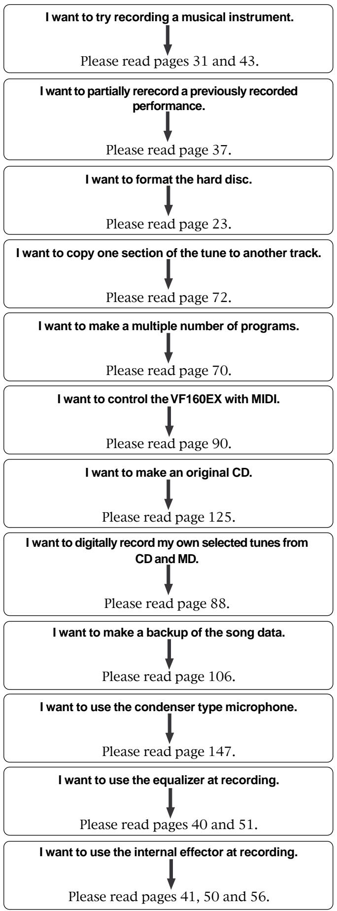
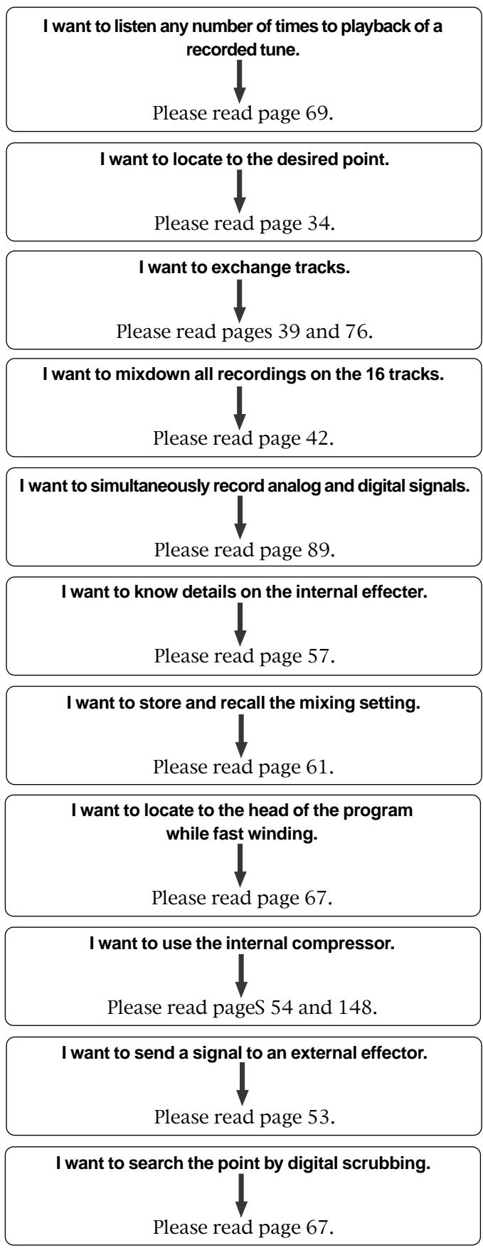
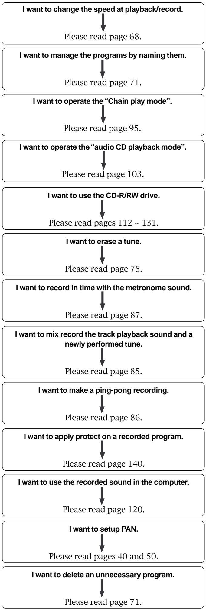
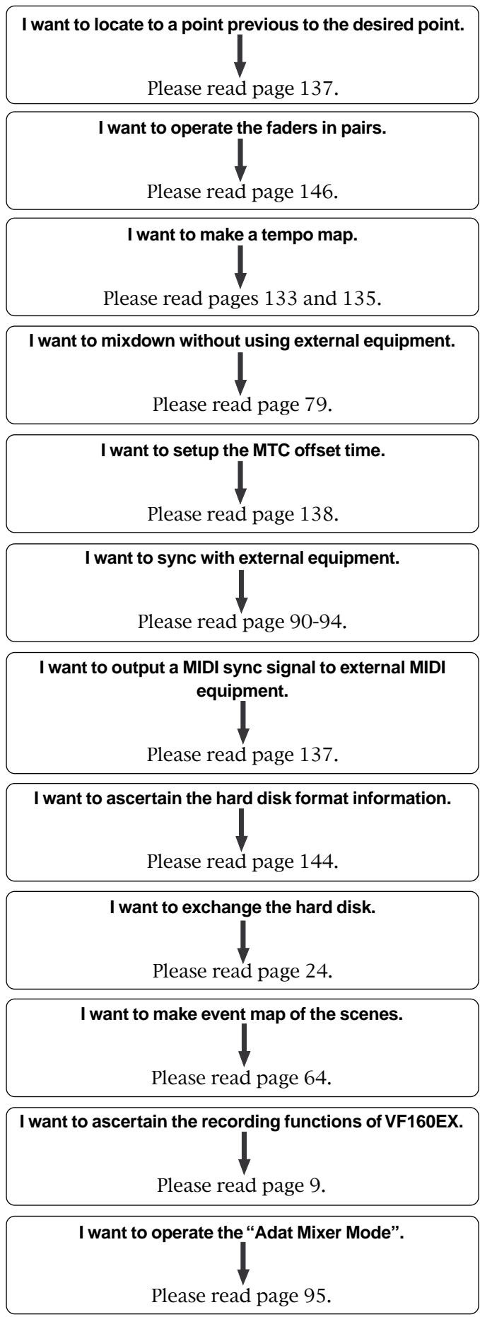
Table of Contents
Safety Instruction 2
Precautions 3
Index for Applications 4
Chapter 1 Basic Features of VF160EX
Introduction 8
Product Features 8
Before Operating 9
- Two RECORDING Modes 9
- RECORDING System 11
PROGRAM 11
- REMAIN Indicator 11
CHANNEL and TRACK 12
- ADDITIONAL TRACK 12
- INPUT Monitoring and PLAYBACK Monitoring 12
EVENT 12
TRIM. 13
FADER. 13
- [CHSTATUS/CHSEL] key............13
TIMEBASE 14
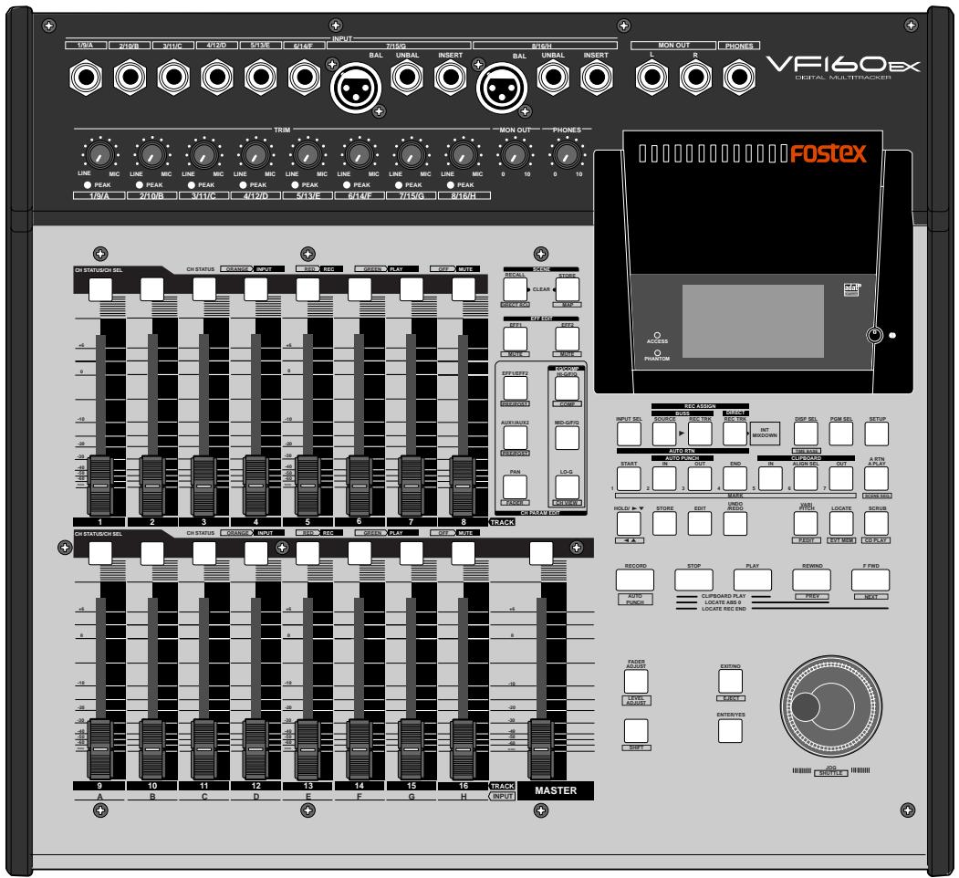
Names and Functions 15
- Top Panel (Analog Input/Output Section) 16
- Top Panel (Mixer Section) 17
- Top Panel (Recorder Section) 19
- Top Panel (Display Section) 22
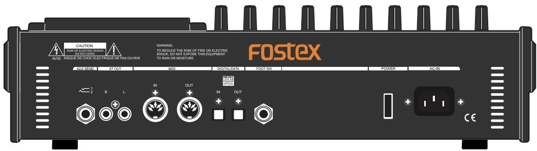
Rear Panel 22
- Front Panel 22
About the hard disk storage device 23
Reformatting the hard disk 23
- Replacing a hard disk 24
- Formatting the new hard disk 26
Chapter 2 Basic Recording and Playback
About demonstration song! 27
Connections of Peripheral Equipment 28
LCD 29
- Menu shown when turning power ON............29
- Switching the Time Base 29
- Switching with [DISPSEL] key 30
Instructions for DIRECT Record 31
- Recording to One Track 31
- Recording to Two Tracks 33
Locate Function 34
ABSLocate 34
- Locating a mark point using a Memory and Mark key .....34
Saving on the Memory key and Mark key .....35
Direct Location of Memory key or Mark key 35 Changing the Time Saved in the Memory key and Mark key .35
- Locating an event memory 36
Creating an event memory 36
Viewing the event memories 36
Locate by specifying the event memory 36
Skiplocate. 36
Punch In/Out 37
Track Exchange 39
Mixing 40
- Level Adjustment 40
PAN Adjustment 40
Equalizer Adjustment 40
- Effect Send Level Adjustment 41
- Modifying Effect Type 41
Mix Down 42
- Analog Mix Down 42
Digital Mix Down 42
Instructions to Record with BUSS RECORD. 43
- Recording the "H" Input Signal to Track 1 44
- Recording 8 INPUTs to Tracks 7 and 8 ..... 46
Chapter 3 Advanced Mixer Operations
Initial condition when the power is turned on 49
Operation while the Normal Display is shown 49
Fader 49
- Channel mute and Solo function 49
- Master channel mute 49
- Adat Mixer Mode (Input monitoring of all tracks) .....49
Channel Parameter Edit 50
- Adjusting PAN 50
- Adjusting EQ. 51
- Controlling Effect send level 52
- Selecting pre/post of Effect sends 52
- Controlling AUX SEND level 53
- Selecting pre/post of AUX sends. 53
- Controlling fader levels 54
- Setting the compressor 54
- Channel view. 55
Effect Edit Mode 56
- About the effect types 57
- Selecting the effect type 58
- Effect parameter settings 59
- Effect parameter details. 59
Scene Memory 61
- Storing to a scene memory 61
- Recalling a scene memory 62
- Level adjust 62
Fader adjust 62
- Direct recall of a scene memory 63
Clearing a scene memory 63
Scene Event Map 64
- Creating an event memory 64
- Creating the scene event map 65
- Deleting an event memory 65
- Scene sequence mode on/off selection 66
- Executing the scene sequence 66
Chapter 4 Recorder Functions
Cueing/Digital Scrubbing 67
- Cueing with the [F FWD]/[REWIND] key............67
- Shuttle Cueing 67
- Digital scrubbing with the [SCRUB] key 67
Variable Pitch Control 68
- Variable Pitch Control ON/OFF 68
- Setting the Speed 68
Auto Function 69
- Auto Play 69
- Auto Return 69
Set (Store) Start/End Point 69
- Auto Repeat 69
Program 70
- Creating a New Program 70
- Selecting a Program 71
Erasing a Program 71
- Editing a Program Title 71
Editing the Track 72
- Copy & Paste and Move & Paste 73
Executing Copy (or Move) and CLIP 73
Pasting Data 73
Undo/Redo Paste 74
Erase 75
Erasing Data 75
Undo/Redo Erase 76
Track Exchange 76
- Executing Track Exchange 76
Exchange in 8-track units. 77
Exchange in mono or 2-track units. 77
Chapter 5 Features Application
Applications of DIRECT RECORD 78
- DIRECT RECORD while listening to the input signal .....78
Internal Mixdown Mode 79
- Activating the internal mixdown mode. 80
- Rehearsing internal mixdown recording. 81
Performing internal mixdown mode. 81
- Inserting "Silence" at the beginning of a song............83
Applications of BUSS RECORD 85
- Record by mixing the input sound and play sound .....85
- Ping-Pong RECORD 86
Metronome Function 87
Digital Recording 88
- Digital recording from an external digital device 88
Recording 16Tracks at the Same Time 89
MIDI Clock Sync System 90
MIDI Sync/MIDI Machine Control System 91
External MIDl equipment Sync System by the Slave mode. 93
Applications example of "Adat Mixer Mode" 95
ChainPlayfunction. 96
Making the chain play list 99
- Setting the chain play mode 99
- Editing the chain play list. 100
Audio CD playback mode 103
- Switching the playback mode. 100
- Available functions in the audio CD playback mode .....104
Chapter 6 Save/Load of Song Data
Save/load of song data using the S/PDIF or adat digital Signal..107
- Saving data using the S/PDIF or adat digital signal .....108
- Loading data using the S/P DIF or adat digital signal .....110
Save/Load using CD-RW/CD-R 112
- Saving data using a CD-R/RW drive (Backup) 115
Carring out "full erasure" 117
- Loading backup data from a CD-R/RW drive............118
Save/Load of WAV files using a CD-R/CD-RW drive. 120
- Saving a WAV file 121
- Loading a WAV file 123
- Making an audio CD. 125
- Loading from an audio CD 129
Chapter 7 SETUP Mode
To enter the SETUP mode 133
Time Signature Setting 133
Setting aTempo 135
Setting the Metronome function 136
Setting a preroll value 137
Setting MIDI sync output signal 137
Setting an MTC frame rate 138
Setting an MTC offset value 138
Setting MTC offset mode 139
Setting the Slave mode 139
Setting the Slave type 140
Setting the Record Protect function 140
Setting Digital Output 142
Setting BAR/BEAT Resolution mode 142
Setting the MIDI device number 143
Checking the number of track events 143
Fader Fix Mode Setting 144
Fader Recall mode Setting 145
Pair fader Setting 146
On/Off of Phantom Power Setting 147
Compressor Channel Setting 148
Trouble Shooting
Troubles at recording? 149
Having trouble Editing? 150
Others
MIDI Implementation Chart 151
MMC Command List 152
Inquiry Message List 152
Maintenance 153
Specifications 153
Block Diagram 155
Chapter 1 Basic Features of VF160EX
Introduction
Congratulations! You have chosen a truly unique multitracking device.
The VF160EX Fostex Digital Multitracker features a myriad of high-tech functions. These include a digital mixer incorporates high-performance DSP multi-effect made possible using the Fostex-original A.S.P. (Fostex Advanced Signal Processing) technology, as well as an integrated 16-track (+8 additional tracks) digital recorder that can record or play uncompressed 44.1kHz / 16 bit high quality sound.
Please read the entire User's Manual to ensure safe and proper use of your recorder.
Product Features
Mixer Section
- Standard high performance DSP multi-effects with A.S.P. Fostex Advanced Signal Processing technology.
- Intuitive control of all signals with 16-input and stereo master fader.
- All input channels come with channel ON/OFF switch, 3-band equalizer, PRE/POST switchable 2-channel EFF/AUX send.
- All 8 channel analog inputs come with built-in trim. Mic to line level compatibility.
- Analog channel input 7 and 8 come with phones connector and XLR connector for phantom power. Built-in insert terminals.
- 2 Record Assigns: DIRECT Rec to simultaneously record 8 analog channels and REC BUS Rec for ping-pong recording. 16-track simultaneous recording of adat digital signals in DIRECT Rec.
- Built-in Scene Memory function to set fader/effect setting and to program/search up to a maximum of 99 mixer modes.
- Output mixed-down signals as S/P DIF digital signals and digital record with DAT and other external digital recorders.
- You can mixdown within the VF160EX itself by utilizing the internal mixdown mode. In addition, a CD of the mixdown can be recorded.
- Using the built-in CD-R/RW drive, you can burn an audio CD from internally mastered songs.
Recorder Section
- Employs the FDMS-3 (Fostex Disk Management System-3) Fostex format. 16-track (plus 8 additional tracks) REC/PLAY with high quality uncompressed 16 bit/44.1kHz sound. Roughly 3 hour recording per 1GB in mono-track.
-
Nondestructive voice editing of copy/paste, move/paste, erase, and undo/redo features as expected from a digital recorder.
-
PROGRAM feature names musical pieces and manage up to a maximum of 99 titles.
- +/-6% pitch control.
- CD S/P DIF or adat digital signal direct digital recording.
- Auto punch IN/OUT with rehearsal function set in 1/100 frame units. Foot switch for manual punch IN/OUT.
- The chain play function allows continuous playback of desired programs.
- Audio CD playback is possible. You can play back audio CDs created by the VF160EX (or commercially available audio CDs) using the built-in CD-R/RW drive.
Others
- Dot matrix LCD and auto-illuminating keys. Graphic display of mixer and recorder settings/ modes.
3.5-inch E-IDE hard disk compatibility.
- You can save/load SATA, as well as WAV files, to/from CD-RW or CD-R discs.
- Save/load to S/P DIF or adat digital signal.
- MIDI clock and song position pointer and MTC (MIDI Time Code) output.
- MMC (MIDI Machine Control).
- Slave program (run) from external MTC input.
- Internal metronome function to rhythm guide recordings.
- Bar/beat edit (cut off clock) with bar/beat resolution.
- Six editing memory points and 7 marked points.
- 0-10 second pre-roll time settings.
Before Operating
This section defines the contents, names and terms the user should know prior to actually operating the VF160EX. Please read the overview before going any farther with your new recorder as it will save you a lot of time in the long run.
Two RECORDING Modes
The VF160EX has 2 recording modes, called REC ASSIGN.
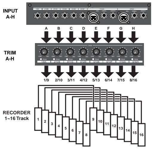
DIRECT Recording
The first recording mode is the DIRECT REC mode.
This recording mode is mainly used to:
- Record signals that are not processed and input in A to H; and
- Simultaneously record all signals input in A to H on separate tracks.
In this mode, the signals input in A to H are gain tuned with the TRIM knob, then directly sent to the recorder track. The tracks are recorded as shown at the input terminal. The A input signals are recorded on track 1/9. Similarly, the B input signals are recorded on track 2/10 and finally the H input signals are recorded on track 8/16.
Therefore, it is possible to easily record on all tracks by simply tuning the gain with the TRIM knob.
Note that the same signals are sent to tracks 1/9 to 8/16. Therefore, when 16 tracks are simultaneously recorded, two tracks of the same sound will each be created. In other words, only a maximum of 8 tracks can be simultaneously recorded with different sounds for input signals A to H.
By using the adat digital input it becomes possible to simultaneously record different sounds on 16 tracks.
BUSS Recording
The second recording mode is the BUSS REC mode. This recording mode is mainly used to:
- Record sounds while applying equalizer and built-in effects; and
- Record (ping-pong recording, etc.) signals mixed on multiple channels on two or one track.
This mode is used to record signals sent to the REC BUSS, that is the recording buss, after the input signal or track play sound is processed through the mixer and level tuned or equalized. Built-in effect signals
can also be sent to the REC BUSS, therefore, sounds applied with an effect can also be recorded.
The channels sent to REC BUSS are called SOURCE.
The REC BUSS comes with L/R 2-channels, therefore, it is possible to simultaneously BUSS REC either 2 or 1 track.

Regardless of whether executing DIRECT or BUSS recording, you must select recording sources and recording tracks.
You can select them using the following keys, depending on the recording mode (DIRECT or BUSS) you are using.
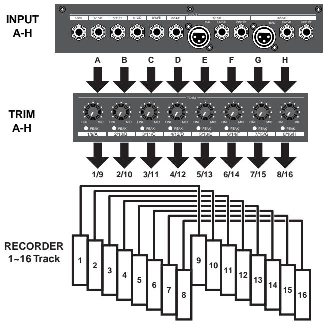
For DIRECT recording:
[INPUT SEL] and [DIRECT RECTRK] keys are used.
The [INPUT SEL] key is used to select the channel sources between the recorder's output signals (TRACK) and input signals (INPUT).
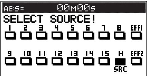
Pressing the [INPUT SEL] key displays the input select screen. Initially, after turning on the VF160EX power (power on default), this screen looks as below, in which all channel sources are set to recorder's output signals.
For DIRECT recording, without changing the setting of the screen above, press the [DIRECT RECTRK] key and specify the recording tracks. This setting is also used for track bouncing via the BUSS recording mode.
![FOSTEX VF160EX - - [INPUT SEL] key - 1](/content/2025/01/168450/images/a4314cc7f1e3b243c4d11dfb50202ea4a63f9768236c3abd5936bb2d44707db7.jpg)
- [DIRECT RECTRK] key
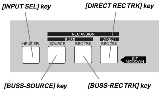
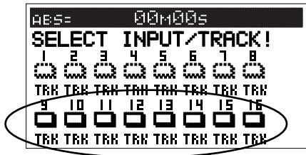
After confirming the input selection by pressing the [INPUT SEL] key, press the [DIRECT RECTRK] key to bring up the track selection screen. The following figure shows that no tracks (1 through 16) are armed. To arm selected tracks, press the appropriate [CH STATUS/CH SEL] keys.
![FOSTEX VF160EX - - [DIRECT RECTRK] key - 1](/content/2025/01/168450/images/1823888fcbb59a98ce37ea6404e1d36a28b79d2cf0b7babaf14398c1b126d435.jpg)
Tips:
Pressing the [CH STATUS/CH SEL] key of channel 1-8 (or channel 9-16) while holding down the [SHIFT] key switches arms all tracks 1 through 8 (or 9 through 16) simultaneously.
The following figure shows that track 1 is armed (READY), so that input A signal can be recorded on track 1.
For BUSS recording:
[INPUT SEL], [BUSS-SOURCE] and [BUSS-RECTRK] keys are used.
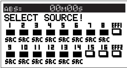
To make "BUSS recording" of input signals, press the [INPUT SEL] key and set source signals to inputs by pressing the [CH STATUS/CH SEL] keys of channels 9 through 16.
In the following figure, the source for channel 16 is set to input H.
![FOSTEX VF160EX - - [INPUT SEL] key - 1](/content/2025/01/168450/images/d9ed6ba55e8a2ee896703c5e0d6def68dc289e90b1432689010caa4e128ab7d2.jpg)
Tips:
Pressing the [CH STATUS/CH SEL] key of channel 9-16 while holding down the [SHIFT] key switches channel sources for all tracks 9 through 16 between "IN" (input A through H) and "TRK" simultaneously.
[BUSS SOURCE] key
The [BUSS SOURCE] key is used to select source channels for BUSS recording.
If you press the [BUSS SOURCE] key when the input select screen is set as the figure shown above (i.e. the source for channel 16 is set to input H), the source select screen as below appears. While this screen is shown, you can select the desired source channel(s) for BUSS recording by pressing the appropriate [CH STATUS/CH SEL] key(s).
![FOSTEX VF160EX - [BUSS SOURCE] key - 1](/content/2025/01/168450/images/8d66e2129e0c53d06a87b2138c175db9d42ab983f3aa30f86232e47e1d967a01.jpg)
Tips:
Pressing the [CH STATUS/CH SEL] key of channel 1-8 (or channel 9-16) while holding down the [SHIFT] key sets all channels 1 through 8 (or 9 through 16) to recording sources simultaneously.
In the following example, channel 16 which accepts input H is selected as a source channel.
If you select channels 1 through 4 and 16 here, tracks 1 through 4 and input H are set as recording sources. Therefore, you can record mixed signals of track and input signals. If you also select "EEF1" or "EFF2", you can record source signals with internal effect.
To bounce tracks, set all channel sources to "TRK" using the "SELECT INPUT/TRACK" and set source channel for recording as shown in the following figure. Then set tracks 15 and 16 as the recording tracks (see "[BUSS-RECTRK] key" below).
- [BUSS-REC TRK] key
The [BUSS-RECTRK] key is used to select "recording tracks" for BUSS recording.
After setting the recording source(s) as described above, press the [BUSS-RECTRK] key to bring up the screen such as below, so that you can select recording tracks for BUSS recording.
![FOSTEX VF160EX - - [BUSS-REC TRK] key - 1](/content/2025/01/168450/images/9496417260ff0570c7857983b4d3a78954f36696541ca42e9f2ec1cbab935bb0.jpg)
While this screen is displayed, you can select the recording track(s) by pressing the appropriate [CH STATUS/CH SEL] key(s).
In the following example, channel 16 which accepts input H, is set as a source channel for BUSS recording to track 1. You can select a mono or a pair of odd/even tracks as the BUSS recording track(s). Note that you cannot select a track whose number corresponds to a source channel as the recording track.
![FOSTEX VF160EX - - [BUSS-REC TRK] key - 2](/content/2025/01/168450/images/2746ebd07cd86115dffcbf88f710525a4175466db5d507230ce5d48a2dadd332.jpg)
RECORDING System
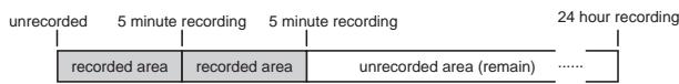
Unlike conventional systems, the VF160EX records on a hard disk storage device, instead of cassette tape. Sound source recording can start from any point on a formatted disk, as long as the point is within a 24 hour time range in ABS time. Note that it is also possible to move (locate) to any point within that time range, as well. Just think of the VF160EX as coming with a tape that is pre-programmed with a 24 hour counter.
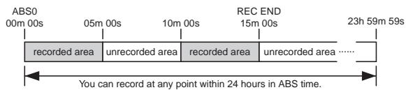
The REC time of cassette tape type recorders vary according to the REC time of the tape. Recording with the VF160EX is more efficient since unrecorded areas of the disk are not used although the REC time is not unlimited.
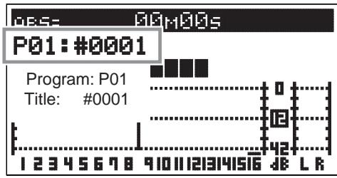
PROGRAM
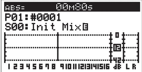
You can use up to a maximum of 99 "24-hour time counted tapes" with the VF160EX. This tape is called a "Program". Note that a program exists individually on the hard disk. Therefore, each respective program can be freely recorded, played and edited without affecting other programs. A program can be named with a program title, making it easier to identify and file the musical piece. In the usual menu, the Program appears on the LCD as shown in the following Figure.
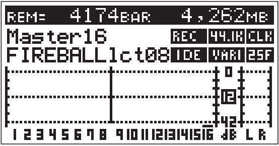
REMAIN Indicator
The REMAIN indicator shows how much recording time is left on hard disk in use.
The VF160EX is controlled with a 24-hour clocked program. Note that the REC time varies according to how much space there is left on the hard disk.
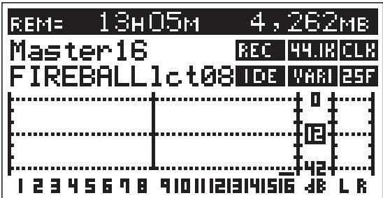
By switching the LCD, the VF160EX remain display appears in the following manner, as shown in the figure below. The rough recordable time is on the hard disk is computed in terms of a mono-track basis. The value indicates the available recordable time and disk space when recording one mono track.
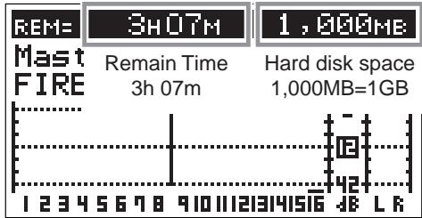
A mono-track refers to one track. Therefore, a mono-track REMAIN time is the recordable length on the hard disk space available when recording only one track.
It is possible to compute the recordable time by dividing the REMAIN time with the number of tracks to record. Therefore, if four tracks are simultaneously recorded, then the recordable time is 46 minutes (3 hours 7 minutes divided by 4). If eight tracks are simultaneously recorded then the recordable time is 23 minutes (divided by 8), and for sixteen tracks the recordable time would be 12 minutes (divided by 16).
The VF160EX manages up to 99 programs on the hard disk. Note that the space on the hard disk is slightly reduced as the number of programs increase, since each program contains various settings, in addition to the REC data.
Therefore, it is important to always check the REMAIN time left prior to starting the recording, to ensure that you have enough hard disk space to work with.
A shortage of hard disk space will stop the recording.
CHANNEL and TRACK
According to this manual, "channel" refers to mixer items and "track" refers to recorder items.
For example, a sentence may read as follows.
"One track of recorder play music will be started on the channel 1 fader of the mixer." "Eight channels worth of signals from input A to H will be recorded on tracks 7 and 8 of the recorder."
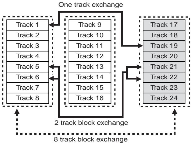
ADDITIONAL TRACK
One program on the VF160EX consists of 24 tracks.
The user can record, play and edit Tracks 1-16.
There are also 8 additional tracks (17-24). These 24 tracks can be alternately exchanged in one track, two track (stereo pair) or an 8 track block. This is called track exchange.
This makes it possible to record solo parts on several tracks, exchange the parts and compare the results. The rhythm section recorded on multiple tracks can also be completely exchanged and remixed with this feature, which is a convenience in numerous ways.
Note that tracks 17-24 cannot be recorded, played or edited. They must be exchanged with tracks 1-16 to execute these features.
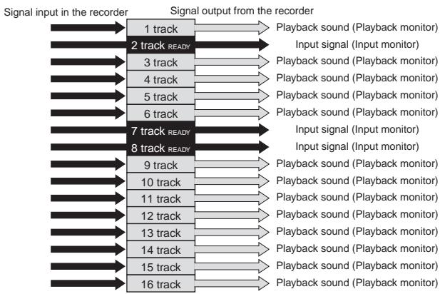
There are two ways to monitor the signal output (track sound) from each track with the VF160EX recorder: input monitoring and playback monitoring.
Playback monitoring means that the track output is the sound that is played. This feature is generally used to playback and listen to sounds that have already been recorded. Playback monitoring is generally used to playback sound.
Input monitoring means the signals (sounds to be recorded) input on that track are directly sent to the track output. This feature is used to check the REC level of the sound to record. Therefore, tracks that are able to be input monitored are either in the "READY" or recording state.
EVENT
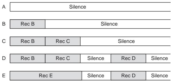
When recording with the VF160EX, an independent audio file for each recording is respectively created on the tracks recorded. Remember that silence is also recognized as one 0 file. These audio files and 0 (silent) files are called an "events". A total of 512 events can be created for each track with the VF160EX. An excess of 512 events cannot be recorded. It is rare that this happens in normal use. The VF160EX is also complete with the function to indicate the current number of events. An alarm will sound when exceeding the maximum number of events authorized. This problem can be resolved by saving or loading the program (procedures described later) in such case. The following are specific examples of the number of events.
A. The VF160EX counts the silent portion of a silent track, which is counted as one file, but not recorded with any sound. Therefore, this means that there will be one file on the track.
B. One audio file is created when recording sound on a track. Therefore, this means that there will be two files on the track.
C. A new audio file is created when consecutively recording. Therefore, this means that there will be three files on the track.
D. An audio files is created after a 0 file, when re-recording after fast forward. Therefore, this means that there will be five files on the track.
E. When straddling (b) and (c) to record, the track will have four files, and thus, the number of events are reduced.
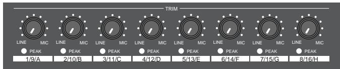
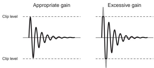
TRIM
It is important to take care when analog signals input are converted into digital signals (A/D conversion) when recording with the VF160EX.
TRIM is used to tune this process and the PEAK LED is used to monitor the process.
If the trim gain is too high ([PEAK] LED illuminated) for the analog signals input into [INPUT] A to H, then the signals input will be converted into distorted (clipped) digital signals, which will sound like noise.
Once converted with this noise, it is not possible to eliminate this distortion from the sound with the mixer or recorder. Therefore, it is important to tune the [TRIM] to a level where the "PEAK" LED fluctuates between the illuminating or not point at the maximum volume of the signal input.
FADER
The VF160EX features 16 channel faders and 1 master fader. Among the faders, the faders for channels 1 to 8 are always started up with output signals from the recorder of tracks 1 to 8 (PLAYBACK or INPUT
Monitoring) to adjust this level. The master fader is always used to adjust the output level of the stereo output.
"Signals input from A to H" or "signals output from the recorder" can be selected as signals to fade and the fade level can be adjusted with faders for channels 9 to 16.
This is a way to easily record with the minimum faders along with the earlier mentioned "2 recording modes."
It is not possible to mix the playback sound of tracks 9 to 16 if inputs A to H are started for all channel faders of 9 to 16. However, this can be prevented, since during normal use, the number of signals input are reduced when recording to tracks 9 to 16 (leaving only the solo part, etc.).
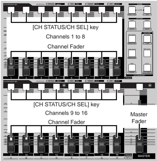
[CH STATUS/CH SEL] Key
The [CH STATUS/CH SEL] Key is the most important key when operating the VF160EX.
The status and contents of operation varies according to selections made with this key.
- Under normal conditions, the key illuminates or flashes to indicate that the signal is input "INPUT" into the current channel fader, the playback sound "TRACK" is started, or the track is ready to record (READY).
Pressing the [CH STATUS/CH SEL] key alone switches between on and off (mute) of the corresponding fader. Pressing this key while holding down the [SHIFT] key switches between on and off of the solo function.
![FOSTEX VF160EX - [CH STATUS/CH SEL] Key - 1](/content/2025/01/168450/images/12940a79df73df082aed8258b0ac4320c7b1dd8e9ce94356406476773bd969f1.jpg)
- To set the send level to the built-in effect or set the equalizer settings of each channel, press the keys to set each parameter shown in the figure below and then press the [CH STATUS/CH SEL] key to select the channel to set.
It is possible, for example, to set the PAN of one channel signal when the channel 1 [CH STATUS/CH SEL] key is pressed after pressing the [PAN] key. All channels can be set by pressing the [CH STATUS/CH SEL] key of channels 1 to 16.
- When the [CH STATUS/CH SEL] key is pressed, the status will require selection of either "INPUT" or "TRACK" for channel faders 9 to 16, as mentioned earlier.
Therefore, operate only the [CH STATUS/CH SEL] key of channels 9 to 16 to switch between "INPUT" or "TRACK," each time the key is pressed.
![FOSTEX VF160EX - [CH STATUS/CH SEL] Key - 2](/content/2025/01/168450/images/a2049875fafb78f12160582f2a43369ad7bb445918b8f599bd663ef1e4a2725f.jpg)
- When pressing the [BUSS-SOURCE] key, the status will require selection of a channel to send to "REC BUSS", as mentioned earlier. Therefore, the channel in which the [CH STATUS/CH SEL] key is pressed is sent to the "REC BUSS".
All channels are selected up to this point.
The following two types only select tracks.
- It is possible to select the track to record (REC READY) in each respective REC mode by pressing the [BUSS-RECTRK] key and [DIRECT-RECTRK] key.
TIME BASE
The term "Time Base" frequently appears in the text of this manual. The time base plays the same role as the "tape counter" of conventional tape recorders, and is used to show the location of the recorder.
There are 3 types of time bases:
- ABS (Absolute Time) indication
- BAR/BEAT/CLK (Bar, Beat, Clock) indication
- MTC (MIDI Time Code)
The user can switch between time bases by pressing the [DISP SEL/TIME BASE] key, while the [SHIFT] key is depressed.
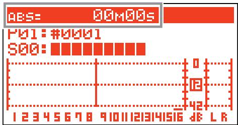
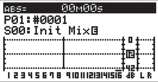
An ABS (Absolute Time) base is the "absolute time" of the hard disk. A time base counter between 00H 00M 00S (ABS 0) and 23H 59M 59S is created when
creating a program. According to the following figure, the recorder is located at a 00M (minute) 00S (second) ABS point. The H (hour) appears when the ABS exceeds the one hour mark. ABS 0 is the universal standard point to manage the recorder location, and correlates with other time bases.
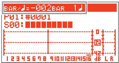
BAR/BEAT/CLK indicate the "Bar, Beat, Clock" that are created with the tempo map (beat and tempo) of the VF160. According to the following figure, the recorder is located at -002BAR (Bar 2) 1BEAT (Beat 1) of the BAR/BEAT/CLK. BAR/BEAT/CLK set the ABS 0 location as Bar -002 as the offset position.
The location of the bar thereafter is determined according to the beat and tempo setting.
The default setting of ABS 0 is set at Bar -002, however, this setting is variable between Bars -009 and -002.
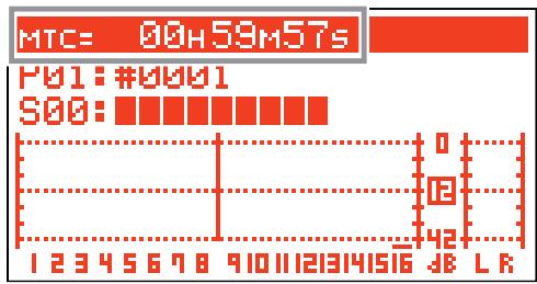
MTC set the ABS 0 location to MTC ^H^M^**S . In other words, MTC sets the time base to start MTC from a certain time, which serves as the offset time, to synchronize the following 24 hour MTC time base with the ABS to count the time. If, for example, ABS 0 is set to MTC 1H, then MTC starts from 1H and ABS 1H (one hour elapsed) will be MTC 2H.
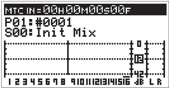
The MTC time set as ABS 0 is called the "MTC Offset". According to the figure below, the current location of the recorder is at MTC 00H (hour), 59M (minutes), 57S (seconds).
The default setting of the MTC offset is set to 00H 59M 57S 00F 00SF. This time base can be changed to any 24 hour clock.
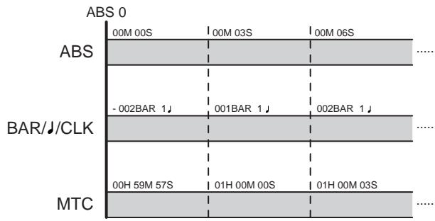
It is also possible to change the setting to Bar 001 and Beat 1 of BAR/BEAT/CLK, instead of using the ABS 0 location point.
The following illustrates the relationship between the 3 time bases.
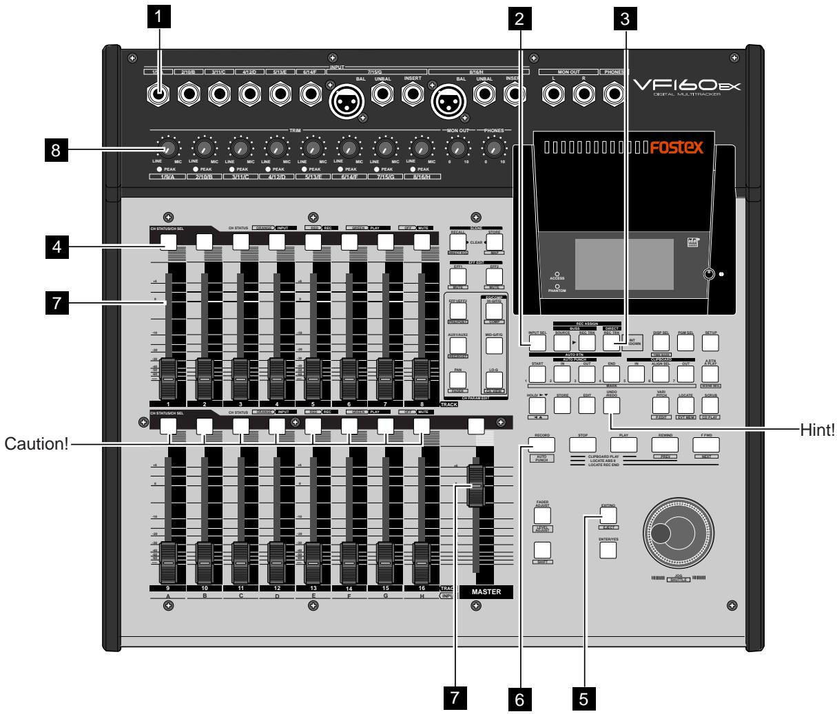
Names and Functions
*1. All keys on the panel will be indicated with a [ ] around the name in this manual.
Example: [PLAY] key, [INPUT] terminal, etc.
*2. All keys that require the [SHIFT] key to be depressed to take effect will be underlined.
Example: [EFF EDIT-EFF1/MUTE] key, etc.
*3. Channel is represented as "ch" and track as "trk" according to the contents.
Example: ch1 fader, trk16, etc.
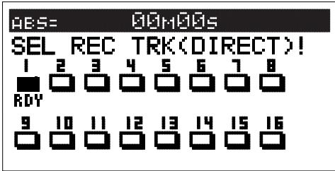
Top Panel
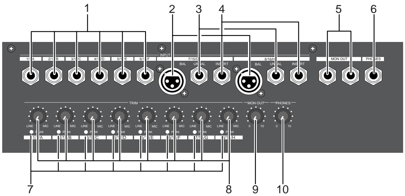
- This adjusts the unbalanced output of the external sound source.
- Standard Input Level: -50dBV to +2dBV
- Connector: Phones jack
- Connect to the balanced output of the external sound source.
- Standard Input Level: -50dBV to + 2dBV (approx. -48dBu to +4dBu)
- Connector: XLR-3-31 type (No. 2 Hot)
- Phantom power (+48V) for condenser mics.
- This input is disconnected when [INPUT UNBAL] jacks G and H are plugged.
- Connections with unbalanced output from external sound source.
- Standard Input Level: -50dBV to +2dBV
- Connector: Phones jack
- [INPUT UNBAL] jacks G and H are disconnected when this input is plugged.
4. [INSERT] Jack: G, H
- External effector (generally a compressor/limiter, etc.) only used for G and H channel input is connected.
- Standard Input/Output Level: -10dBV
- Use a Y-cable, as shown below, to connect an external effector since the Ø6 TRS phones jack is used.
![FOSTEX VF160EX - [INSERT] Jack: G, H - 1](/content/2025/01/168450/images/fb7a046bbf2702df8e6ac17919b392543e85ef1e95fdf8949cc9f314b614c26f.jpg)
5. [MON OUT] (Monitor Output) Jack: L, R
- Connect a speaker with internal amp or amp + speaker for monitoring purposes.
- Standard Output Level: -10dBV
- Connector: Phones jack
6. [PHONES] (Headphones) Jack
- Headphones connection for monitoring purposes.
- Connector: TRS Phones jack
7. [PEAK] LED: 1 to 8
- Lights ON if the input signal is approx. 2dB lower than the clipping level.
- Tune the [TRIM] knob whether to light ON or OFF the LED for the gain.
8. [TRIM] Knob: 1 to 8
- Adjusts the gain according to the input signal.
- Gain is adjustable between -50dBV (MIC) and +2dBV (LINE).
9. [MON OUT] (Monitor Output) Knob
- Adjusts the output level from the [MON OUT] jack.
10. [PHONES] (Headphones) Knob
- Adjusts the output level form the [PHONES] jack.
For more details, refer to the respective instructions of each item.
Top Panel
Mixer Section
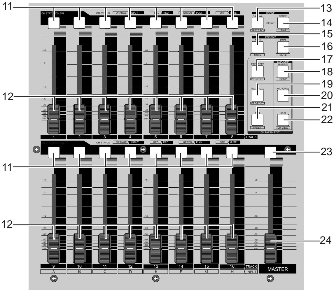
11. [CH STATUS/CH SEL] Key: channels 1-16
- ON/OFF key for each channel during normal display (explained later).
- Select the channel to CHECK/CHANGE the setting with ([CH PARAM EDIT] Key (No. 17-22) when CHECKING/ CHANGING various PAN, equalizer and other mixer parameters.
- Select the recorder track (1-16) for REC READY or REC CANCEL (SAFE) status (flashing [REC ASSIGN-DIRECT] key or [REC ASSIGN-BUSS] key]) when selecting the track to record.
- Pressing the [CH STATUS/CH SEL] key alone switches between on and off (mute) of the corresponding fader.
- Pressing this key while holding down the [SHIFT] key switches between on and off the solo function.
- The flashing key illustrates the following STATUS:
[ORANGE]: The level of the input signals [INPUT] into input A to H are adjustable. Only channels 9-16 are adjustable with the fader.
[GREEN]: The level of the audio [TRACK (PLAY)] on the track are adjustable with the fader. It will continue to flash when the SOLO function is ON.
[OFF]: The signals to the fader are [MUTE] (no sound).
[RED]:
The corresponding tracks (1-16) are READY (to record). The [GREEN] and [RED] key will alternately flash. The light will remain ON during the recording process.
12. Channel Fader: channels 1-16
- The 1-8 channel faders are used to adjust the audio level [TRACK] of tracks 1-8.
- The 9-16 channel faders are used to adjust the sound level of signals input into A to H or audio levels [TRACK] of 9-16. Use the [INPUT SEL] key to choose which level to adjust.
13. [SCENE-RECALL/DIRECT RCL] Key
- This is used to recall the scene memory.
- Press this key while the [SHIFT] key is depressed for direct scene memory recall.
- Simultaneously press this key and the [SCENE-STORE/ MAP] key to erase the scene memory.
14. [SCENE-STORE/MAP] Key
- This is used to store scene memory.
- Press this key while the [SHIFT] key is depressed to CHECK/CHANGE the scene map.
- Simultaneously press this key and the [SCENE-RECALL/DIRECT RCL] key to erase the scene memory.
15. [EFF EDIT-EFF1/MUTE] Key
- This is used to CHECK/CHANGE the EFFECT type and parameter settings of EFFECT 1.
- Press this key while the [SHIFT] key is depressed to turn ON/OFF the mute feature of EFFECT 1.
16. [EFF EDIT-EFF2/MUTE] Key
- This is used to CHECK/CHANGE the effect type and parameter settings of EFFECT 2.
- Press this key while the [SHIFT] key is depressed to turn ON/OFF the mute feature of EFFECT 2.
17. [CH PARAM EDIT-EFF1/EFF2/PRE/POST] Key
- This is used to CHECK/CHANGE the send level settings of EFFECT 1 or EFFECT2. The EFFECT 1 and EFFECT 2 settings alternate every time the key is pressed.
- Press this key while the [SHIFT] key is depressed to CHECK/CHANGE the PRE/POST settings of EFFECT 1 or EFFECT 2.
- Use the [CH STATUS/CH SEL] Key to select the channel to change any settings together.
18. [CH PARAM EDIT-EQ/COMP-HI/G/F/Q/COMP] Key
- This is used to CHECK/CHANGE the high frequency parametric equalizer settings. The parameter settings alternate every time the key is pressed.
- Press this key while the [SHIFT] key is depressed to CHECK/CHANGE the COMPRESSOR settings.
- Use the [CH STATUS/CH SEL] Key to select the channel to CHECK/CHANGE any settings together.
19. [CH PARAM EDIT-AUX1/AUX2/PRE/POST] Key
- This is used to CHECK/CHANGE the send level settings of AUX 1 or AUX 2. The AUX 1 and AUX 2 settings alternate every time the key is pressed.
- Press this key while the [SHIFT] key is depressed to CHECK/CHANGE the PRE/POST settings of AUX 1 or AUX 2.
- Use the [CH STATUS/CH SEL] Key to select the channel to change any settings together.
20. [CH PARAM EDIT-EQ/COMP-MID-G/F/Q] Key
- This is used to CHECK/CHANGE the midrange frequencies of the parametric equalizer settings.
- Press this key while the [SHIFT] key is depressed to CHECK/CHANGE the settings.
21. [CH PARAM EDIT-PAN/FADER] Key
- This is used to CHECK/CHANGE the PAN settings.
- Press this key while the [SHIFT] key is depressed to show the current fader location. Finer level adjustment is possible by using the [JOG] dial.
- Use the [CH STATUS/CH SEL] key to select the channel to change any settings together.
22. [CH PARAM EDIT-EQ/COMP-LO-G/CH VIEW] Key
23. [MASTER CH STATUS/CH SEL] Key
- This becomes the master channel ON/OFF key when the LCD is in the normal display mode (described later).
- Select the channel to CHECK/CHANGE any settings with the ([CH PARAM EDIT] Key (No. 17-22)] to CHECK/CHANGE any PAN, equalizer or other mixer settings.
- The STATUS of the key lights ON are defined below.
[GREEN]: The level of the stereo buss L, R outputs are adjustable with the fader.
[OFF]: The signals to the master fader are [MUTE] (no sound).
24. [MASTER] Fader
- This is used to adjust the master level of the sound signals output from the STEREO OUT L, R jacks.
For more details, refer to the respective instructions of each item.
Top Panel
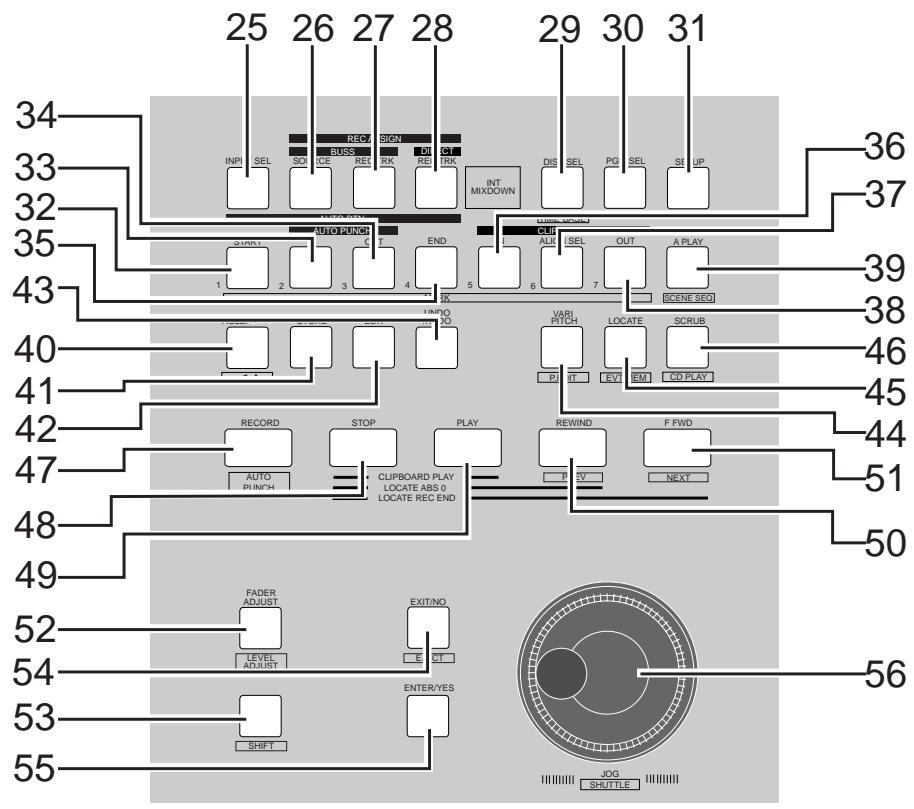
Recorder Section
- Set whether to send the A to H input signals [INPUT] or track 9-16 play [TRACK] sounds to the faders of channel faders 9 to 16.
- When executing DIRECT recording, with the [SHIFT] key pressed down, each time the [INPUT SEL] key is pressed while in the normal display mode, the input monitor (READY) can be switched ON/OFF for all tracks (1-16). However, any track that is setup to [IN] (Input) by the INPUT SEL setting ([IN]-[TRK]) cannot be changed to input monitor.
26. [REC ASSIGN-BUSS-SOURCE] Key
- Select the channel (SOURCE) to send to the REC BUSS during "BUSS" recording. Select the SOURCE channel with the [CH STATUS/CH SEL] key.
- This key lights ON when the SOURCE is selected.
27. [REC ASSIGN-BUSS-RECTRK] Key
- The track (READY) to record in "BUSS" recording is selectable when this key is flashing. Set READY track with the [CH STATUS/CH SEL] Key.
- This key lights ON when the READY track is set for "BUSS" recording.
28. [REC ASSIGN-DIRECT-RECTRK] Key
- The track (READY) record in “DIRECT” recording is selectable when this key is flashing. Set READY track with the [CH STATUS/CH SEL] key.
- This key lights ON when the READY track is set for "DIRECT" recording.
29. [DISP SEL/TIMEBASE] Key
-
This key is used to alternate the menu shown on the LCD in the following order.
-
The tracks recorded vary, as shown below, according to the connection jack.
a. Current location of TIME BASE selected
Shows the current location of the sound.
b. REMAINING TIME BASE Selected (time remaining)
Shows the time remaining and space available on the disk for recordings (in terms of mono track).
Shows the MTC time input in the [MIDI IN] jack.
This is a convenience for operations as a slave device.
- The user can switch between time bases, as shown below, by pressing the [DISP SEL/TIME BASE] key, while the [SHIFT] key is depressed.
a. ABS (Absolute Time) Indication
An absolute time base from 00H 00M 00S (ABS 0) to 24H 00M 00S.
b. BAR/BEAT/CLK (Bar)
The "Bar, Beat, Clock" of the beat and tempo set with the internal tempo map.
c. MTC (MIDI Time Code)
Display of the MTC time setting.
30. [PGM SEL] Key
- This is used to switch between programs 01 to 99.
This is also used to create new programs.
31. [SETUP] Key
- This is used to go into the setup mode to set various parameters of the recorder and mixer.
32. [AUTO RTN-START/MARK1] Key
- This key is used to CHECK/CHANGE the parameters saved at the start point (AUTO RETURN START POINT) when executing auto return or auto repeat.
- Press this key while the [SHIFT] key is depressed to CHECK/CHANGE the parameters saved in [MARK1].
- This can be used as Locate Memory.
33. [AUTO PUNCH-IN/MARK2] Key
- This key is used to CHECK/CHANGE the parameters saved at the recording start point (PUNCH IN POINT) when executing auto punch in/out, paste or erase.
- Press this key while the [SHIFT] key is depressed to CHECK/CHANGE the parameters saved in [MARK2].
- This can be used as Locate Memory.
34. [AUTO PUNCH-OUT/MARK3] Key
- This key is used to CHECK/CHANGE the parameters saved at the recording end point (PUNCH OUT POINT) when executing auto punch in/out or erase.
- Press this key while the [SHIFT] key is depressed to CHECK/CHANGE the parameters saved in [MARK3].
- This can be used as Locate Memory.
35. [AUTO RTN-END/MARK4] Key
- This key is used to CHECK/CHANGE the parameters saved at the end point (AUTO RETURN END POINT) when executing auto return or auto repeat.
- Press this key while the [SHIFT] key is depressed to CHECK/CHANGE the parameters saved in [MARK4].
- This can be used as Locate Memory.
36. [CLIPBOARD-IN/MARK5] Key
- This key is used to CHECK/CHANGE the parameter saved at the start point (CLIPBOARD IN POINT) when copying from or pasting to the clipboard.
- Press this key while the [SHIFT] key is depressed to CHECK/CHANGE the parameters saved in [MARK5].
- This can be used as Locate Memory.
37. [CLIPBOARD-ALIGN SEL/MARK6] Key
- This key is used to CHECK/CHANGE the parameter saved at the align point (ALIGN POINT) when copying/pasting or moving/pasting.
- Press this key while the [SHIFT] key is depressed to CHECK/CHANGE the parameters saved in [MARK6].
- This can be used as Locate Memory.
38. [CLIPBOARD-OUT/MARK7] Key
- This key is used to CHECK/CHANGE the parameter saved at the end point (CLIPBOARD OUT POINT) when copying from or pasting to the clipboard.
- Press this key while the [SHIFT] key is depressed to CHECK/CHANGE the parameters saved in [MARK7].
- This can be used as Locate Memory.
39. [A RTN/A PLAY/SCENE SEQ.] Key
- Every time this key is pressed the mode switches from Auto Play -> Auto Return -> Auto Repeat -> OFF, and this mode is shown on the LCD.
![FOSTEX VF160EX - [A RTN/A PLAY/SCENE SEQ.] Key - 1](/content/2025/01/168450/images/d378b480796272ad7a6dc89b4f439df358ab36537590618fab4167c622a9e8d7.jpg)
- Press this key while the [SHIFT] key is depressed to turn ON/OFF the scene sequence.
When scene sequence is switched "on", the normal display section "S**" will change to reversed black and white display.
40. [HOLD/>] Key
- This key is used to hold the parameter (time or BAR/ BEAT/CLK) when the key is pressed. The parameter is simultaneously displayed and is editable.
- When this key is pressed at editing of the value, the digit can be moved to the right or below, and if this key is pressed while pressing on the [SHIFT] key, it can be moved to the left or above.
41. [STORE] Key
- This key is used to store the edited parameters (time or BAR/BEAT/CLK) to the editing point (AUTO PUNCH POINT, etc.), MARK point, LOCATE MEMORY, etc.
42. [EDIT] Key
- This key is used to copy, past and edit the sound. The following 5 types of sound editing types are possible.
a. [Copy Clip]
b. [Move Clip]
c. [Copy Paste] or [Move Paste]
d. [Erase]
e. [Track Exchange]
43. [UNDO/REDO] Key
- This key is used to copy, past and edit sound as well as cancel and undo the auto punch in/out, recording and other processes.
- Press this key again to return to the state prior to undo (redo).
44. [VARI PITCH/P.EDIT] Key
- Every time this key is pressed the mode alternates between VARI PITCH (PLAY/REC at different speed) ON (Key: Light ON)/OFF (Key: Light OFF).
- Press this key while the [SHIFT] key is depressed to alter the speed variation (Pitch Edit).
45. [LOCATE/EVT MEM] Key
- This key is used to locate the editing point (AUTO PUNCH POINT, etc.) and Mark Point.
- The last located parameter is saved as the parameter of this key, every time. Therefore, it is possible to simply press this key to go to the last located point (LAST LOCATE).
- Press this key while the [SHIFT] key is depressed to edit the parameter saved in Event Memory (Event number 01-99).
46. [SCRUB/CD PLAY] Key
- This is used to digitally scrub sounds in the FWD and REV direction without any change in pitch.
- Pressing this key while holding down the [SHIFT] key switches the playback mode between HDD playback and audio CD playback.
47. [RECORD/AUTO PUNCH] Key
- Press the [PLAY] key while this key is depressed (or press this key while the [PLAY] key is depressed) to start recording the READY track. (Key: Light ON)
- The READY track goes in the input monitor mode when only this key is pressed (Key: Flashing).
Pressing this key again cancels the input monitor and the READY track goes to the Playback Monitor mode.
- Press this key while the [SHIFT] key is depressed to turn ON/OFF AUTO PUNCH.
48. [STOP] Key
- Press this key during PLAY, REC, F FWD, REW to stop recorder operations.
- Press this key in the SETUP mode to escape one stage each from the SETUP mode.
- Press the [PLAY]/[REWIND]/[F FWD] key while this key is depressed for the following operations.
- This is used to CANCEL/PAUSE the SETUP menu settings, copy/paste and various other sound editing processes.
\[STOP] + [PLAY]:CLIPBOARD PLAY
Play the sound that is copied or moved to the clipboard.
[ \text{[STOP]} + \text{[REWIND]}: \text{LOCATE ABSO} ]
Locate the beginning of the ABS (ABS = 00M 00S 00F) of the current program.
[ \text{[STOP]} + \text{[F FWD]}; \text{LOCATE REC END} ]
Locate the portion in which sound is recorded (REC END) on the current program.
49. [PLAY] Key
- Press this key to start playing the recorder.
- Press the [RECORD] key while this key is depressed (or press this key while the [RECORD] key is depressed) to start recording the READY track.
- PUNCH OUT (REC CANCEL) takes place when only the [PLAY] key is pressed during the recording process.
- Press this key while the [STOP] key is depressed to start "CLIPBOARD PLAY".
50. [REWIND/PREV] Key
- Press this key while the machine is stopped for 30X rewind speed.
- 3X cuing (rewinding with sound) takes place when this key is pressed during the PLAY status.
- Press this key while the [SHIFT] key is depressed to locate the “PREV” (previous) memory (locate the previous event memory).
- Press this key while depressing the [STOP] key to "LOCATE ABS 0".
- Press this key while editing the parameters to move the column (digit) to edit.
51. [F FWD/NEXT] Key
- Press this key while the machine is stopped for 30X rewind speed.
- 3X cuing (rewinding with sound) takes place when this key is pressed during the PLAY status.
- Press this key while the [SHIFT] key is depressed to locate the "NEXT" memory (locate the next event memory).
- Press this key while depressing the [STOP] key to "LOCATE REC END".
- Press this key while editing the parameters to move the column (digit) to edit.
52. [FADER ADJUST/LEVEL ADJUST] Key
- This key flashes during scene memory recall, etc. to notify the user that the currently set fader parameter and the internally set fader position are not the same.
- Press this key to go to the Fader Adjust Mode. The internally set fader position is checked. By adjusting the fader setting manually it is possible to adjust the actual fader position according to the internally set fader position.
- Press this key while the [SHIFT] key is depressed to go to the Level Adjust Mode. This forcibly adjusts the volume to the current fader position.
53. [SHIFT] Key
- This key is used as the function key for various keys and dials that have a shift function.
The key functions are shown at the bottom of the key if the key has a shift function.
54. [EXIT/NO/EJECT] Key
- This is used to CANCEL/PAUSE the SETUP menu settings, copy/paste and various other sound editing processes. This key is the opposite of the [ENTER/YES] key.
55. [ENTER/YES] Key
- This is used to SET/EXECUTE the SETUP menu settings, copy/paste and various other sound editing processes. This key is the opposite of the [EXIT/NO] key.
56. [JOG/SHUTTLE] Dial
- Turn ON the [SCRUB] key, press [CH STATUS/CH SEL] key of a voluntary channel, then turn the jog dial for digital sound scrubbing in the FWD and REV direction without any change in pitch.
- Turn this dial while the [SHIFT] key is depressed to F FWD/REW between a shuttle speed of 1X to 64X depending on the degree the dial is turned.
- The jog dial can be used to increase/decrease the parameter settings during the editing process.
For more details, refer to the respective instructions of each item.
Top Panel
Display Section
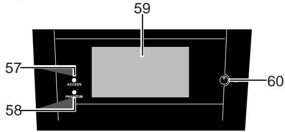
57. [ACCESS] LED
- This LED lights ON when the internal hard disk drive or external SCSI device for backup purposes is writing or reading data.
58. [PHANTOM] LED
- This lights ON when the phantom power is ON. The phantom power is turned ON/OFF with the setup mode.
59. LCD (Liquid Crystal Display)
- The recorder and mixer status and parameters are shown on the LCD.
60. Contrast Adjusting Knob
- This is used to adjust the contrast (difference in brightness) of the LCD. Increase or decrease the contrast by turning it clockwise or counterclockwise, respectively.
Rear Panel
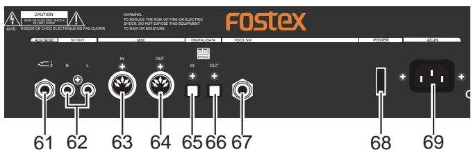
61. [AUX SEND-1/2] Jack
- External effector or other devices are connected to output the AUX SEND 1/2 signals.
- Standard Output Level: -10dBV
- Use a Y-cable, as shown below, to connect an external effector since the 06 TRS Phones jack is used.
![FOSTEX VF160EX - [AUX SEND-1/2] Jack - 1](/content/2025/01/168450/images/a4ae23a9c3ca67820a822f68e1207f4b571892911af3e2d224b4d8ab1b8d5c67.jpg)
62. [ST OUT-L/R] Jack
- Master recorders and other devices are connected to output stereo L/R signals.
- Standard Output Level: -10dBV
- Connector: RCA (pin)
63. [MIDI IN] Jack
64. [MIDI OUT] Jack
- Connect to the MIDI IN jack of an external MIDI device.
- MIDI synchronization signals such as MTC (MIDI Time Code) and MIDI clock signals & song position pointers are mainly output.
- Connector: DIN 5 PIN
65. [DIGITAL/DATA IN] Jack
- Connect to OPTICAL DIGITAL OUT (S/P DIF) or adat DIGITAL OUT of an external digital device for signal input to the VF160EX.
- This is used to load DAT/adat song data.
- Connector: Square optical
66. [DIGITAL/DATA OUT] Jack
- Connect to OPTICAL DIGITAL IN (S/P DIF) or adat DIGITAL IN of an external digital device for signal output from the VF160EX.
- This is used to save DAT/adat song data.
- Connector: Square optical
- Punch IN/OUT option by connecting the Fostex Model 8051 foot switch (unlatched type).
68. [POWER] switch
69. [AC IN] Jack
- This turns ON/OFF the power of the VF160EX.
- This is where the accessory power cable is inserted.
For more details, refer to the respective instructions of each item.
Front Panel
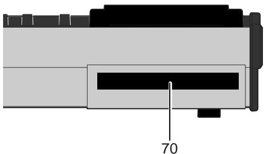
70. CD-R/RW drive
- After turning the power on, pressing the eject key in the front of the drive opens the tray. To close the tray, push the front of the tray lightly by your hand.
Using the CD-R/RW drive, you can also save/load song data to/from a CD-R or CD-RW disc, or burn an original audio CD.
About the hard disk storage device
The VF160EX is complete with a 3.5-inch E-IDE hard disk (storage device) which is formatted in the Master 16 mode. Therefore, there is no need to newly assemble a hard disk or to format the hard disk. The user can immediately start recording with the VF160EX. Note that the current hard disk can also be replaced with another model for use with the VF160EX. (However, please only use hard disks that Fostex recommends.)
This section describes how to reformat the hard disk. The VF160EX adopts a "FDMS-3 (Fostex Disk Management System-3)" format which is a Fostex exclusive format. Eight additional tracks can be used in addition to recording and playing 16-tracks of uncompressed 44.1kHz / 16 bit high quality sound.
Note that, when you reformat your hard disk, you will erase all data saved or recorded on the hard disk, as well as all the settings made. Reformating your hard disk restore the VF160EX back to the default setting.
Always make a point to check that there is no data that you need remaining on the hard disk prior to reformatting.
1. Turn ON the VF160EX.
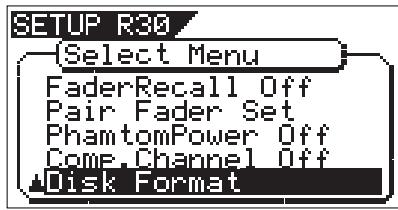
2. Press the [SETUP] key.
The system will go to the SETUP mode. The select display of the SETUP menu appears. (The highlight indicates the menu that is currently selected.)
![FOSTEX VF160EX - Press the [SETUP] key. - 1](/content/2025/01/168450/images/92e73b211ac0099e84bf324af3fdd53ad48d4c16fd3c8320f262f9f3f6239e9c.jpg)
The menu to select the format type appears.
The display will appear as follows, according to the previous format type. "**" represents the name of the drive.
![FOSTEX VF160EX - Turn the [JOG] dial to highlight the "Disk Format" menu title, press the [ENTER/YES] key. - 1](/content/2025/01/168450/images/7424dc62e5327a9cd31189d19401483f8194294273d055fd7b93845de42a95d1.jpg)
![FOSTEX VF160EX - Turn the [JOG] dial to highlight the "Disk Format" menu title, press the [ENTER/YES] key. - 2](/content/2025/01/168450/images/e93f3b430722d60397e470389b1206814c7de7d0bf607b6f2d47bcb1fe5ac55e.jpg)
The hard disk formatted in the "Standard" type upon newly formatting the hard disk will show "Standard" and "Erase". The hard disk formatted in the "Quick" type upon newly formatting the hard disk will show "Standard" and "Quick". The user can select one.
| Standard | The hard disk is formatted with the access time of the unit sectors, while judging whether the sectors are good or bad. The formatting time tends to be longer with this type, however, the reliability is better. Therefore, it is recommended that this default format type is selected under normal conditions. |
| Erase | This choice is only available when a hard disk previously formatted in the “Standard” type is being reformatted. With this format, the “Standard” type is maintained, while all data on the hard disk are erased. The formatting time is shorter than the time required to format a “Standard” type. |
| Quick | This is a quick formatting procedure in which all hard disk sectors are considered to be good sectors. The formatting time is fast, however, the procedure cannot discover bad sectors. Therefore, it is recommended that this format type is only used when formatting a new hard disk that Fostex has already confirmed to operate normally. |
The format type selected is set and "Sure?" flashes.
![FOSTEX VF160EX - Select the format type with the [F FWD] key or [REWIND] key. Then press the [ENTER/YES] key. - 1](/content/2025/01/168450/images/38d8f45cacb391e3ae1fbb0ded28e39db58e7a51c5b1fd68a9db12f27e87318f.jpg)
5. Press the [ENTER/YES] key while the [RECORD] key is depressed.
If the "Standard" format is selected and executed, the formatting process takes place while showing the progress of the good sectors (Good MB) on the disk, bad sectors on the disk (Bad MB) and remainder (Remain ***MB). Nothing can be done during the formatting process. Please wait for a while until the process is completed.
![FOSTEX VF160EX - Press the [ENTER/YES] key while the [RECORD] key is depressed. - 1](/content/2025/01/168450/images/44c35b859d9687f3de17933c9e631e8801288e38d4f981f0c5bcde01e79cf48b.jpg)
When the hard disk is successfully formatted (formatting completed), the number of sectors and noncontiguous sectors are shown after formatted, then "Completed!" lights up. Formatting is completed instantaneously if either "Erase" or "Quick" is selected and executed. For this reason, the "Completed!" message lights up without showing the progress status while formatting is taking place.
![FOSTEX VF160EX - Press the [ENTER/YES] key while the [RECORD] key is depressed. - 2](/content/2025/01/168450/images/2d109d425fd65ecb649c79f0a3e92d18a7bf846dc8d8690ff061840819ba73d8.jpg)
6. Press the [EXIT/NO] key (or [STOP] key) to escape from the SETUP mode.
The Normal Display appears indicating the beginning of the program (P01) that is automatically created after formatting the hard disk.
Replacing a hard disk
The updated information on the operation-confirmed HD and backup media for VF160EX is mentioned in the following Fostex international web site.
http://www.fostex.co.jp/int/index.htm
For those who are unable to check our web site, please contact the Fostex distributor in your territory.
This section describes the procedures to replace the hard disk. However, we recommended that the customer ask the Fostex Customer Service Department to replace the VF160EX hard disk. Note that the product is not warranted for any malfunctions that may occur after the customer replaces the hard disk on their own. Also note that Fostex will not be held liable for any accidents that may occur during the replacement process or any hard disk damages, if the customer decides to replace their own hard disk on their own.
- Always turn OFF the power of the VF160EX and unplug the power plug from the electric outlet when replacing the hard disk.
- Always place the hard disk on a flat and stable platform during the replacement process. Place a soft cloth under the unit to protect the product from scratching. Gloves are recommended to prevent any hand injuries.
- A hard disk is an extremely sensitive precision device. Never expose the hard disk to "strong shocks" when replacing, assembling or handling. Never leave the hard disk by a device that generates strong magnetic fields.
- Always set the DIP switch and Jumper of the newly assembled hard disk to the [Cable Select] setting. The hard disk will not operate normally if the setting is set to [MASTER] or [SLAVE] when the hard disk is assembled. Refer to the User's Manual of the hard disk for more details on the DIP switch and Jumper settings.
- Note that the connector of some hard disks may be stiff, and thus make it difficult or impossible to insert or connect. Never apply excessive force to insert the connector in such case. Always make a point to gently insert the connector. Failure to do so may result in unexpected injuries or damage the hard disk.
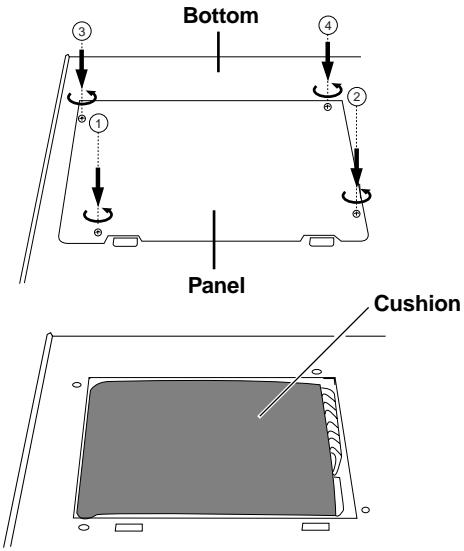
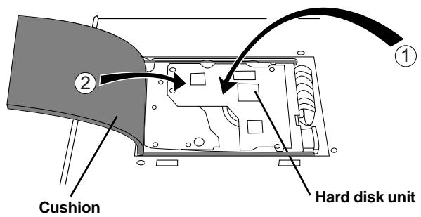
1. Unscrew the four screws fixing the panel to the bottom of the VF160EX main unit.
If the panel is removed, the hard disk covered with a cushion can be seen.
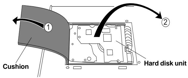
2. Take out the hard disk to the direction "2" indicated in the drawing below.
Slightly lifting up the cushion upward helps you take out the hard disk easily.
When taking it out, do not apply excessive force.
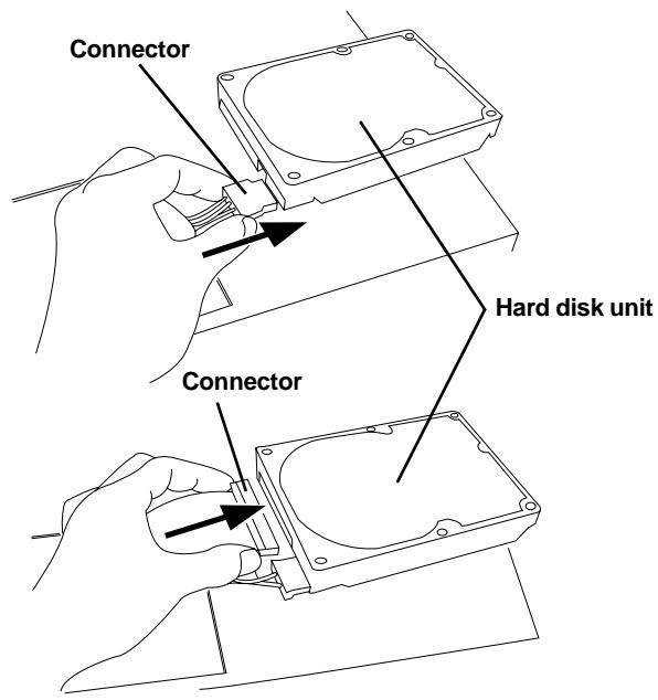
3. Hold the connector section and gently pull out the two cable connectors from the hard disk.
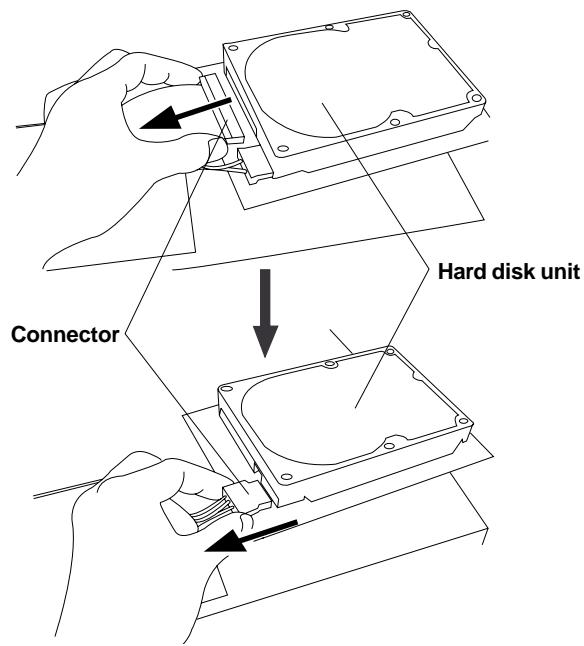
4. Prepare a new hard disk and connect the two cable connectors to it with holding the connector section.
5. Put back the new hard disk into the VF160EX main unit.
In the reverse order of taking out the hard disk as performed earlier, carefully house the hard disk at the bottom of the main unit and cover it with the cushion.
6. After checking that the cables, etc. are not sticking out from the main unit, put the panel onto the hard disk and the case.
Align the position of screw holes on the panel / case with the VF160EX bottom panel screw holes and fix the panel / case using the four screws to the VF160EX main unit.
When the new hard disk is successfully assembled, go to the next section. Now, format the unformatted hard disk.
Carefully follow the instructions below to newly format the hard disk properly.
1. Turn ON the VF160EX after plugging the power cable in the electric outlet.
The VF160EX will startup. "Unformat!" will appear on the LCD. The menu will automatically go to the SETUP mode. The display showing the "Disk Format" menu appears.
2. Press the [ENTER/YES] key.
The menu to select the format type appears. **** represents the name of the drive.
![FOSTEX VF160EX - Press the [ENTER/YES] key. - 1](/content/2025/01/168450/images/effac2576dcee1811d533924ae88a08001ffd41505e6651bb2433eae20befb1f.jpg)
Either the "Standard" or "Quick" format type can be selected. However, make sure that the "Standard" format type is selected when formatting a newly installed hard disk.
3. Press the [ENTER/YES] key where the "Standard" is flashed.
The format type selected is set and "Sure?" flashes.
4. Press the [ENTER/YES] key while the [RECORD] key is depressed.
The formatting process is started. The formatting process will take some time.
When the formatting is successfully completed,
"Completed!" will light up on the display.
5. Press the [EXIT/NO] key (or [STOP] key) to escape from the SETUP mode.
The Normal Display appears indicating the beginning of the program (P01) that is automatically created after formatting the hard disk.
![FOSTEX VF160EX - Press the [EXIT/NO] key (or [STOP] key) to escape from the SETUP mode. - 1](/content/2025/01/168450/images/5e5ab007b369075ae0e34d57553ce470cbffcbad0ec92db1c1d1fb0efcedc5b1.jpg)
Chapter 2 Basic Recording and Playback
This chapter describes basic recording and playback with the VF160EX.
Before carrying out recording/playback, read “About a demonstration song!”, “Connections of Peripheral Equipment” and “LCD”.
About a demonstration song! (Read this before using the unit)
Your VF160EX may have a demonstration song on program 1 (P01) when shipped (note that some VF160EX units may not have a demonstration song, depending on the production). Please check whether a demonstration song is recorded or not on your unit according the following manner.
After turning on the unit and boosting up program 1, press the [PLAY] key to start playback.
- If the level meters move:
A demonstration song is recorded.
Title of the recorded demonstration song will be indicated for the program title.
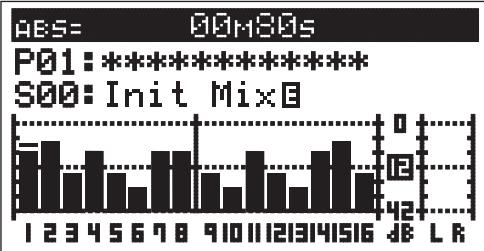
- If the level meters do not move:
No demonstration song is recorded.
Temporary title such as "#0001" will be indicated for the program title.
If a demonstration song is recorded, you can listen to the song any time by playing back program 1 (see page 31 for details about how to play back a program).
Note that you cannot record a new material on program 1 if a demonstration song is recorded on program 1. Therefore, before starting recording for the first time, you must carry out any of the following operations.
Note: You can start recording without the need for carrying out any of the following operations if no demonstration song is recorded on your unit.
If you wish to start recording while keeping the demonstration song
Create a new program.
The newly created program is not record-prohibited, so you can record a material onto it.
See page "70" for details about how to create a new program.
If you wish to record a material on program 1 (overwriting the demonstration song)
Set "Rec Protect" menu in the setup mode to "Off".
Now you can overwrite the demonstration song on program 1 by a new material.
See page "140" for details about how to make the record-protect setting to "Off".
If you wish to record a material onto program 1 after deleting the demonstration song
Delete program 1.
After deleting program 1, a new blank "program 1" is automatically created onto which you can record a new material.
See page "71" for details about how to delete a program.
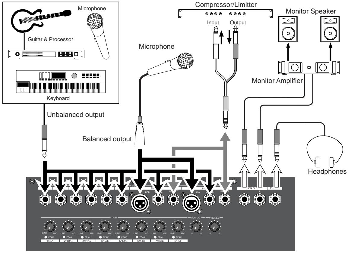
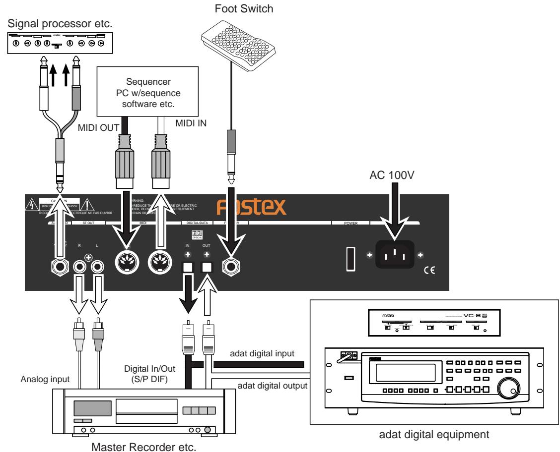
Connections of Peripheral Equipment
The VF160EX is equipped with input/output jacks to connect the following sound sources and external equipment.
Always turn the [MASTER] fader, [MON OUT] knob and [PHONES] knob to “0” when connecting the external equipment to the input/output jacks.
LCD
The following describes the contents shown on the LCD and their operations.
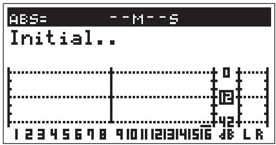
When the VF160EX is turned ON with a hard disk already formatted, the following menu will appear in order: [Initial... (Initializing)] & [Version] -> [Current Dr] -> [IDE] -> [Name of Hard disk (Instantly)] -> [Recording mode (Standard or Quick)].
The head of the program (ABS 0) will then start up at the time base when the power was turned OFF.
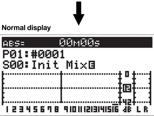
The LCD menu appearing immediately after turning the power ON is called the "Normal Display".
The "Normal Display" shows the following items for the 3 time bases:
- Current Location/Program Number & Program Title
- Scene Number & Scene Name
- Level Meter of Tracks 1-16
- Stereo OUT L/R Master Level/Meter
Switching the Time Base
The user can switch between time bases, by pressing the [DISP SEL] key, while the [SHIFT] key is depressed. In this case the time base alternates in the order of “1. ABS” -> “2. BAR/BEAT/CLK” -> “3. MTC” -> ... The normal display always appears when the time base is switched. Make use of these displays accordingly.
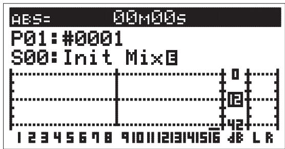
Time Base: Normal Display in ABS.

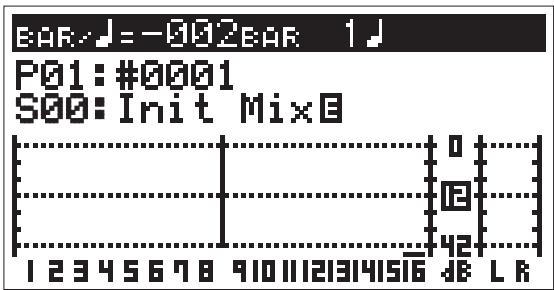
Time Base: Normal Display in BAR/BEAT/CLK.

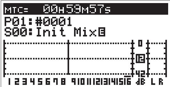
Time Base: Normal Display in MTC.
Switching with [DISP SEL] Key
Every time the [DISP SEL] key is pressed the LCD alternately shows the "1. Normal Display of Current Time Base" -> "2. REMAIN Display of Current Time Base" -> "3. MTCTime Display Input". The description of each display is defined below.
1. Normal Display of Current Time Base
- Current time according to current time base.
- Program number and program title.
The first 9 characters of the program title are shown.
- Scene number and scene name.
The first 9 characters of the scene name are shown.
- Level meter of tracks 1 to 16.
- L/R master level meter
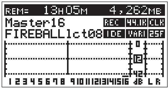
2. REMAIN Display of Current Time Base
- REMAIN time and space available in mono-track converted units according to the current time base (the following is the case in ABS).*1
- Format type.
- Name of hard disk.
- Level meter of tracks 1 to 16.
- L/R master level meter.
- MTC time input.
"00H 00M 00S 00F" appears if there is no time input.
- Program number and program title.
The first 16 characters of the program title are shown.
- Scene number and scene name.
The first 16 characters of the scene name are shown.
- Level meter of tracks 1 to 16.
- L/R master level meter.
*1. The REMAINING time display appears as follows according to the time base that has been selected.
Time Base: ABS and MTC
Time Base: BAR/BEAT/CLK
*2. Icons of the program setup details appear at the right side of the menu. Refer to examples below.
| REC | This indicates recording/no recording setup by the “Rec Protect” menu. The icon shown here is indicating that it is presently set “Off” and thus recording is possible. |
| 44.IR | This is indicating the VF160EX sampling frequency (Fixed to 44.1kHz). |
| IDE | The icon here is indicating that the current drive is set to an “E-IDE hard disk.” |
| CLK | This indicates the MIDI sync output signal setup by the “Midi Sync Out” menu. The icon here is indicating that it is presently set to “CLK.” |
| VARI | This indicates the slave type setup by the “Slave Type” menu. This icon is indicating that it is presently set to “VARI.” |
| 25F | Frame rate figure setup by the “MTC Frame Rate” menu is indicated here. The icon here is indicating that it is presently set to “25 Frames.” |
Instructions for DIRECT Record
This section describes the basic REC/PLAY procedures in the "DIRECT" recording mode, which is the easiest recording procedure and also provides recordings that most closely resemble the original. Hints and tips to successfully operate the VF160EX are included according to the work flow, ranging from the actual recording to mix down process. Both experienced and novice users of multitracker should try this process so as to learn the VF160EX operations. The following description assumes that the VF160EX has been started up without any recordings.
DIRECT Recording
The figure on the right shows the relations between input channels and recording tracks in the DIRECT recording mode. You can see that up to 8 input channel signals can be recorded simultaneously.
WARNING!
- It is also possible to simultaneously record 16 tracks. However, there will be 2 consecutive tracks on which the same sound is recorded.
- The channel with the ORANGE light ON ([INPUT]) from among ch9-16 of the [CH STATUS/CH SEL] keys cannot output the audio sound on the tracks corresponding to 9-16, therefore, recording will be prohibited. As a result, the READY state cannot be established with the [DIRECT-REC TRK] key.
Recording to One Track
Here, we will record to track 1 of the recorder. Check to see that the channel faders of ch1-16 and the master fader are set to “ - ” (completely down) and that [TRIM] A to H are set to LINE position (fully turn to left). Also use (connect) a headphone or monitor speakers to monitor the sound.
Preparing to Record
1 Connect the sound source to record to the [INPUT] 1/9/A jack.
Press the [INPUT SEL] key (Key: Flashes ORANGE). [CH STATUS/CH SEL] key of ch9-16 -> Flashes GREEN Indicates that all channels are "TRK (Track)" (the following LCD display appears).
WARNING!
In DIRECT Recording, all channel faders are basically "TRK". If there is channel in which the "IN (Input)" (RED: Flashing), press the [CH STATUS/CH SEL] key of that channel so it is a "TRK".
3 Press the [DIRECT-REC TRK] key (RED: Flashing).
The menu to select the track to record appears.
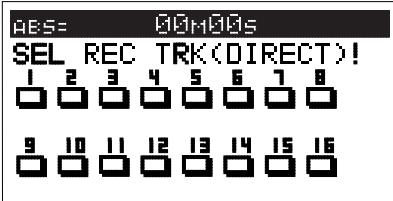
Press the [CH STATUS/CH SEL] key of ch1 (Key: Flashing RED).
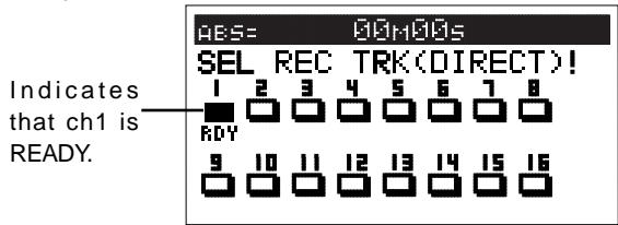
Press the [EXIT/NO] key to return to the Normal Display.
[CH STATUS/CH SEL] key of ch1 -> Alternately Flashes
GREEN/RED
- Indicates that trk1 is "RDY (Ready)".
6 Press [RECORD] key to set trk1 to the Input Monitor mode (Key: Flashing RED).
7 Set the ch1 fader and master fader to "0".
8 Output sound from the sound source while adjusting the [TRIM]1/9/A gain to an optimal level.
The guideline for optimal gain is the border of the [PEAK] LED lighting ON or OFF, when the sound source is at the maximum volume. Adjustments should also ensure that the signal does not exceed 0 on the LCD level meter. To listen to the sound turn up the [MON OUT] knob or [PHONES] knob.
WARNING!
Be careful not to excessively raise the volume of the [MON OUT] or [PHONES] level. Prolonged exposure to loud sounds may have an adverse effect on hearing.
Tips: Level meter
When carrying out step 8 mentioned above, levels for channel 1 and masters L and R are shown in the meters on the Normal display.
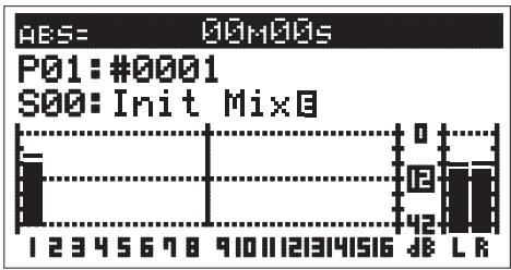
The channel 1 fader controls the signal level sent to the stereo busses L and R, which you monitor.
If you completely drop down the channel 1 fader, you cannot monitor the sound, but the input level of channel 1 (= recording level of track 1) is not affected.
To control the input level of each channel, use the [TRIM] knob as mentioned in step 8.
RECORD
- Press the [REWIND] key while the [STOP] key is depressed, to locate ABS 0 (Locate ABS 0).
- Press the [PLAY] key while the [RECORD] key is depressed to start recording.
The RED light of [CH STATUS/CH SEL] key and [RECORD] key of ch1 lights up to indicate that ch1 is recording.
- Press the [STOP] key to stop the recording operations.
The LCD will show a "Please Wait" message and then return to the Normal Display.
This completes the process to record on track 1.
Check the sound recorded using the following procedures.
Cancel READY Status of Recording Track
Press once again the [DIRECT-RECTRACK] key that is lit up RED, then press the [CH STATUS/CH SEL] key of the channel that is in the READY mode to cancel the ready state of the track recorded and to put that track in the SAFE mode. Then press the [EXIT/NO] key to return to the Normal Display.
PLAY
- Press the [REWIND] key while the [STOP] key is depressed to locate ABS 0.
- Press the [PLAY] key to start playback.
The play level of track 1 can be adjusted with the ch1 fader. This concludes the procedures to check the sound recorded.
Tips: UNDO/REDO
Press the [UNDO/REDO] key after recording to return to the prerecording state (UNDO). Press the [UNDO/REDO] key again to return to the original state of the recording on track 1 (REDO). The UNDO/REDO function is effective for all recordings.
RECORDING to 2Tracks
With track 1 now recorded, we will record the stereo sound source to tracks 15 and 16 of the recorder.
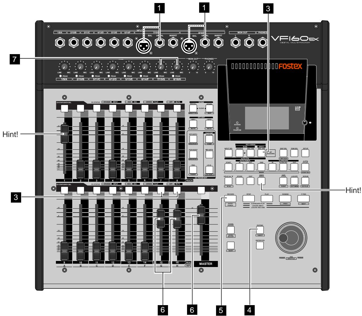
Preparing to Record
1 Connect the stereo sound source to record to [INPUT] jacks 7/15/G and 8/16/H.
Press the [DIRECT-REC TRK] key (RED: Flashing).
Press the [CH STATUS/CH SEL] key for ch15 and ch16 (RED: Flashing).
Trk15 and 16 will go to the "RDY (Ready)" mode. The other tracks will be in the "SAFE" mode (Key: Light OFF).
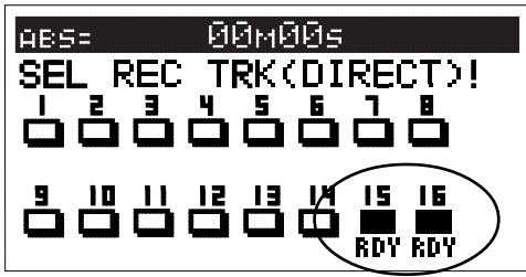
Press the [EXIT/NO] key.
[CH STATUS/CH SEL] key of ch 15 and 16 -> GREEN/RED: Alternately Flash
- Indicates that trk15 and 16 are "RDY (Ready)".
Press the [RECORD] key to put trk15 and 16 in the Input Monitor mode (RED: Flashing).
Trk15 and 16 will get to the Input Monitor mode.
6 Set the ch15 and ch16 fader and master fader to "0".
Tips: How to make a fader pair
You can pair two adjacent faders.
By pairing faders 15 and 16, for example, you can control both channels (15 and 16) simultaneously via a single fader.
See page 146 for details about how to pair faders.
7 Output sound from the sound source while adjusting the [TRIM] 7/15/G and 8/16/H gain to an optimal level.
RECORD
- Locate the time to start recording.
- Press the [PLAY] key while the [RECORD] key is depressed to start recording.
The [CH STATUS/CH SEL] key and [RECORD] key of ch15 and 16 lights up RED to indicate that the channels are recording. By increasing the fader level of track 1, the user can record to tracks 15 and 16 (overdubbing) while listening to the playback sounds of track 1.
- Press the [STOP] key to stop recording.
Tips: Changing the recording mode
To change the DIRECT recording mode to the BUSS recording mode, press the [BUSS-RECTRK] key while the tracks to be directly recorded are selected using the step above. "Rec Mode Change!" appears and "Sure?" flashes on the screen.
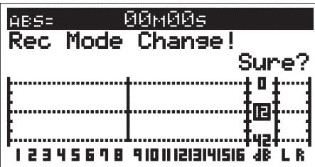
Pressing the [ENTER/YES] key cancels the selection of tracks for the DIRECT recording and changes the display to the track selection screen for the BUSS recording.
Tips: UNDO/REDO
Press the [UNDO/REDO] key after recording to return to the prerecording state (UNDO). Press the [UNDO/ REDO] key again to return to the original state of the recording on two tracks (REDO).
PLAY
- Locate the time to playback.
- Press the [PLAY] key to start playback.
Ch1, ch15 and ch16 faders can be used to adjust the play level of each track.
After recording, put the "READY" track in the "SAFE" mode, as described earlier.
Tips: MUTE
Press the [CH STATUS/CH SEL] key in the Normal Display to MUTE (silence) that channel ([CH STATUS/CH SEL] key: Light OFF).
Locate Function
The VF160EX provides sophisticated locate functions, which allow quick locate to the desired point.
ABS Locate
There are 3 types of ABS Locate procedures. The instructions are described below.
- Press the [REWIND] key while the [STOP] key is depressed to locate ABS 0 which is the head of the program.
That head is located for all time bases.
- Press the [F FWD] key while the [STOP] key is depressed to locate the REC end time of the last recording (REC END).
This is a convenient feature to search the end of a song or to find out how long a song is.
- Press the [RECORD] key while the [STOP] key is depressed to locate the start time of the last recording.
It will locate to "ABS 0" if recording had not been executed even once after switch on of power.
Locating a mark point using a Memory Key and Mark Key
The VF160EX provides seven keys for registering time information. These are called "memory keys".
You can register two time data for each memory key. One is "mark memory" point data, used for locate functions.
The other is time data, which is used for track editing functions such as auto return, auto punch in/out and copy/paste. However, you can also use the latter one for locate functions, when you do not use track editing functions.
Therefore, when you do not use track editing functions, you can store up to 14 locate memory points, while you can store up to 7 memory points when using track editing functions.
The table on the next page shows the data stored for each memory key.
You can do this operation in any time base.
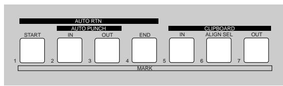
Normally, the [CLIPBOARD-ALIGN SEL/MARK6] key can store the MARK6 memory. When doing a copy/paste (or move/paste) function, the time data stored in the [CLIPBOARD IN] key is automatically copied and stored in this key, allowing you to use it as the ALIGN SEL point. See "Copy/paste and Move/paste" on page 73 for details.
The following details are saved in each Memory Key.
[AUTO RTN-START/MARK 1] Key:
$$
- > \text {S T A R T p o i n t a n d M A R K 1 m e m o r y}.
$$
[AUTO PUNCH-IN/MARK 2] Key:
$$
- > \text {P U N C H I N p o i n t a n d M A R K 2 m e m o r y}.
$$
[AUTO PUNCH-OUT/MARK 3] Key:
$$
- > \text {P U N C H O U T p o i n t a n d M A R K 3 m e m o r y}.
$$
[AUTO RTN-END/MARK 4] Key:
$$
- > E N D p o i n t a n d M A R K 4 m e n o r y.
$$
[CLIPBOARD-IN/MARK 5] Key:
$$
- > C L I P \text {I n}
$$
[CLIPBOARD-ALIGN SEL/MARK 6] Key:
$$
- > \text {A L I N G S E L p o i n t a n d M A R K 6 m e m o r y}.
$$
[CLIPBOARD-OUT/MARK 7] Key:
$$
- > \text {C L I P O U T p o i n t a n d M A R K 7 m e m o r y}.
$$
Saving on the Memory key and Mark key
- Ensure the system is in the PLAY or STOP status. Press the [HOLD/>] key at the time to save.
The time is held on the LCD at the point the [HOLD/>] key is pressed.
LOCATE= 308H31m59s24F995F
HOLD
- Press the [STORE] key (RED: Light ON).
LOCATE= 08H01M59s24F993F Hit Any Memory Keys!
3-1. Press a voluntary Memory key.
The time held is saved as a point of the Memory Key, and then the system returns to the Normal Display.
3-2. Press the [MARK 1-7] key while the [SHIFT] key is depressed.
The time held is saved as a Mark Memory of MARK 1-7, and the system returns to the Normal Display.
Tips: How to check stored time data
To check the memory points, press the desired memory key. To check the mark memory, press the desired memory key while depressing the [SHIFT] key.
Direct Location of Memory key or Mark key
1-1. Press a voluntary Memory key.
The name of the key pressed and the point saved appears on the LCD.
LOCATE=63H61M28s29F8S5F
A.PUNCH IN
1-2. Press the [MARK 1-7] key while the [SHIFT] key is depressed.
The name of the Mark Memory and the time saved appears on the LCD.
LOCATE=00H01M23s23F0915F MARK:1
- Press the [LOCATE] key.
This allows Direct Location to the time shown.
Tips:PREROLL
By setting "PREROLL" in the SETUP mode, it is possible to locate the time (0-10 seconds) several seconds before the time set to locate.
Changing the Time Saved in the Memory key and Mark key
1-1. Press a voluntary Memory key.
The name of the key pressed and the point saved appears on the LCD.
LOCATE= 03H01M28s29F09.sF A.PUNCH IN
1-2. Press the [MARK 1-7] key while the [SHIFT] key is depressed.
The name of the Mark Memory and the time saved appears on the LCD.
LOCATE=08H01M2S520F09sf MARK:1
- Change the parameter of the flashing column (cursor) (H/M/S/F/SF or BAR/BEAT/CLK) using the [JOG] dial.
Move the flashing column (cursor) by pressing the [HOLD/>] key.
- Press the [STORE] key (RED: Light ON).
3-1. Press a voluntary Memory key.
The time modified is saved as the time point of the Memory Key, and the system returns to the Normal Display.
3-2. Press the [MARK 1-7] key while the [SHIFT] key is depressed.
The time modified is saved as a Mark Memory of MARK 1-7, and the system returns to the Normal Display.
Locating an event memory
You can store up to 99 event memory points (00 to 99). These event memory points can be used for locate functions described below as well as for the "scene event map" function described in "Chapter 3 Mixer functions".
Creating an event memory
Event memory numbers are assigned in ascending order of ABS time, regardless of order in which event memories are created.
For example, if you create event memories in order as shown in the upper diagram below, the event memory numbers are assigned as shown in the lower diagram.
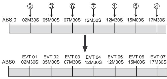
- At the desired position while the VF160EX is stopped or during playback, press the [HOLD/>] key.
The time when pressing the [HOLD/>] key is held on the screen.

- Press the [STORE] key.
The key lights up (in red) and "Hit Any Memory Keys!" appears on the screen.

- Press the [LOCATE/EVT MEM] key while holding down the [SHIFT] key.
"Entry EVT*" (where ** shows the number) appears for a short time, while the time held in step 1 is entered in the event memory.
Viewing the event memories
- Press the [SCENE-STORE/MAP] key while holding down the [SHIFT] key.
The display shows the event number select screen for the scene event map, in which you can view and check the event memories created by the procedure above.
The unit for event memories - ABS, Bar/Beat/Clk or MTC
- depends on the time base setting.
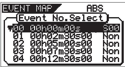
-
Rotate the [JOG] dial to scroll through the event memory list.
-
After viewing the screen, press the [EXIT/NO] key. The display returns to the Normal display.
You can delete unnecessary event memories. See "Editing the event map" in "Advanced mixer operations" described later for details.
Locate by specifying the event memory
- Press the [SCENE-STORE MAP] key while holding down the [SHIFT] key to bring up the event map screen.
- Use the [JOG] dial to select the desired event number, and press the [LOCATE] key.
The unit locate the selected memory point and stops, while the display returns to the Normal display.
When selecting an event memory, you can know the nearest event memory point to the current point by the flashing event number (in the example below, event number 02 is the nearest).
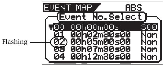
Skip locate
With the Skip locate function using the event memories, the unit automatically recognizes the locate point and locate there. When the Skip locate is executed, the locate point is shown on the screen and you will know where the current position goes.
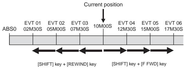
- Press the [REWIND/PREV] key while holding down the [SHIFT] key to skip back to the previous event memory point.
- Press the [F FWD/NEXT] key while holding down the [SHIFT] key to skip advance to the next event memory point.
By sequentially executing the key operation above as many times as required, you can locate the desired event memory. In the above screen, for example, to locate event 01 from the current position, press the [REWIND/PREV] key three times while holding down the [SHIFT] key.
Punch In/Out
Punch IN/OUT recording enables you to record over previously recorded parts. This function comes in handy in the following cases.
- If a recording is unsatisfactory in either recording or performance and you want to redo it.
- If you want to record a solo part to another track while listening to the backup tracks.
PUNCH IN refers to the process to switching from PLAY to REC. On the other hand, PUNCH OUT refers to the reverse process, to switch from REC to PLAY. The time to punch in is called the PUNCH IN point, and the time to punch out is called the PUNCH OUT point. The VF160EX features the following 3 types of PUNCH IN/OUT modes.
- MANUAL PUNCH IN/OUT using the key on the main unit
This feature is used for rough recordings. Manual punch in/out is not recommended during a performance since the process requires using your hands.
- PUNCH IN/OUT using the foot switch
Recording is possible even during a performance since all punch in/out processes are controlled from the foot switch.
Detailed recording is possible since recording takes place with the punch in/out time preset (programmed) prior to the recording.
Use the [DIRECT-RECTRK] key to put the track to record in the READY mode. The [TRIM] must be adjusted to an optimal gain according to the input monitor. When this is set, do the following:
Manual Punch IN/OUT
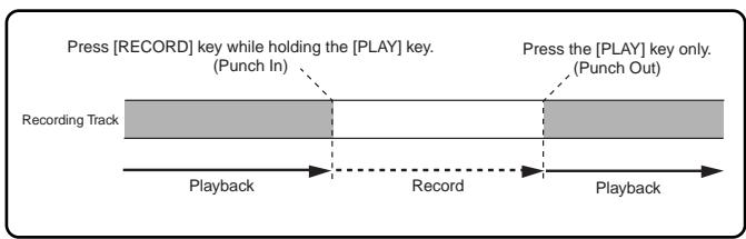
- Press the [PLAY] key from the point immediately before starting the recording and then playback.
- Press the [RECORD] key while the [PLAY] key is depressed to start recording (punch in).
- Recording is canceled and playback takes place if only the [PLAY] key is pressed (punch out).
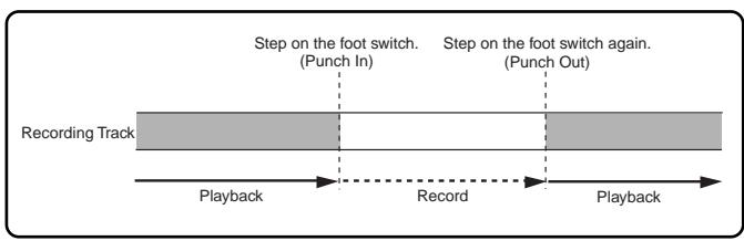
- Connect a "Fostex Model 8051" foot switch to the [FOOT SW] jack on the rear panel of the VF160EX.
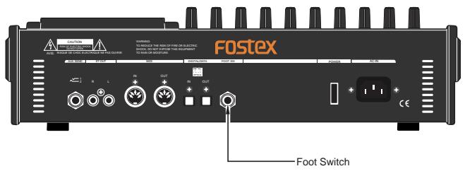
- Press the [PLAY] key from the point immediately before starting the recording, then playback.
- Recording starts by stepping on the foot switch (punch in).
- Recording is canceled and playback takes place when the foot switch is stepped on again (punch out).
Tips:Rehearsal
Step on the foot switch while the [STOP] key is depressed to start rehearsing the recording ("RhrlsOn" will appear on the LCD then "RHSL" will light ON).
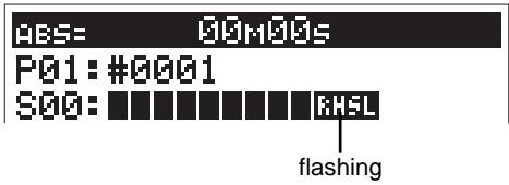
Rehearsal instructions are the same as recording with the foot switch.
However, stepping on the foot switch will go to input monitor, and stepping on it again will cancel it. To cancel the rehearsal mode, step on the foot switch again while the [STOP] key is depressed ("Rhrl Off" will appear on the LCD then "RHSL" will light OFF).
Use the optional Fostex Model 8051 or a universal foot switch of the unlatched type.
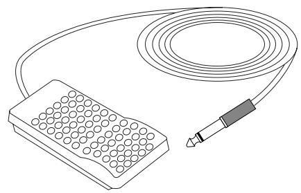
Auto Punch IN/OUT
Before carrying out an auto punch in/out operation, you must register the "PUNCH IN" and "PUNCH OUT" points.
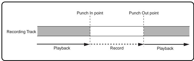
- Programming the PUNCH IN/OUT points
When programming a PUNCH IN/OUT point, the time of the punch IN point must always be before the time of the PUNCH OUT point. If the PUNCH OUT point precedes the PUNCH IN point, a "Void Out!" error message appears on the LCD and prevents use of the AUTO PUNCH mode.
- While the system is in the PLAY or STOP mode, press the [HOLD/>] key at the time to program as the PUNCH IN or PUNCH OUT point.
LOCATE= 86H81H59s24F99sF
HOLD
- Press the [STORE] key (RED: Light ON).
LOCATE=09H01M53s24F39sF Hit Any Memory Keys!
- The PUNCH IN point is programmed when the [AUTO PUNCH IN] key is pressed. The PUNCH OUT point is programmed when the [AUTO PUNCH OUT] key is pressed.
- AUTO PUNCH IN/OUT rehearsal
- Press the [RECORD] key while the [SHIFT] key is depressed to go to the "AUTO PUNCH Mode". "RHSL" starts flashing.
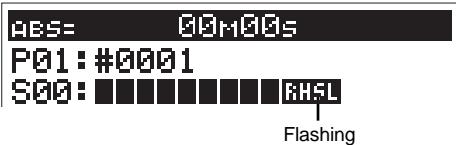
- LOCATE the point immediately before starting the recording.
- If only the [PLAY] key is pressed, the recordings are rehearsed.
"RHSL" steadily lights. In the rehearsal mode, even though recording is not actually executed, the monitor signal for a record-armed track changes to "input" at the punch-in point and returns to "source" at the punch-out point. You can check or adjust the record level and timing in the rehearsal mode as many times as you want until you are satisfied.
- Press the [STOP] key to stop the VF160EX.
- AUTO PUNCH IN/OUT take
- After rehearsal is completed, locate the point immediately before starting the recording, as with step 2 of AUTO PUNCH IN/OUT rehearsal.
- Press the [RECORD] key while the [PLAY] key is depressed to start recording [TAKE].
"RHSL" changes to "TAKE".
The actual recording is made between the PUNCH IN and PUNCH OUT points. At the PUNCH OUT point, recording as well as the AUTO PUNCH mode stops.

- Press the [STOP] key to stop the VF160EX.
Tips: Undo/Redo
If you are not satisfied with the take, you can rerecord after pressing the [UNDO/REDO] key.
Track Exchange
Up to now, we changed the input channel according to the track to record. However, there is also a way to record all tracks with one input jack. You can do this by exchanging a recorded track that was recorded normally with an unrecorded track. This procedure is called "Track Exchange".
This feature is convenient to use when recording with all G and H [INPUT] jacks that can be connected with a condenser mic or balanced output, for example. Note that the VF160EX comes with 16 tracks, plus 8 additional tracks.
The Track Exchange feature makes it possible to exchange these tracks with any unneeded tracks 1-16.
Tips:
The Track Exchange can be done among all 24 real and additional tracks, as shown in the figure below.
You can exchange track(s) in single, stereo, or 8-track units.
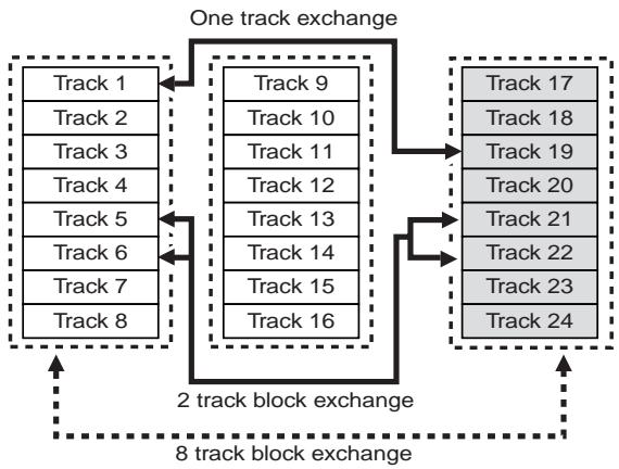
Instructions
For this procedure, you need a recorded track and a blank track.
- Repeatedly press the [EDIT] key while the recorder is in the STOP state to find and display the "Track Exchange" mode.
The mode can also be selected by pressing the [EDIT] key then turning the [JOG] dial.
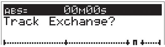
- Press the [ENTER/YES] key.
The track selection menu of the Track Exchange mode appears.
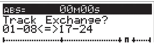
- Turn the [JOG] dial to select the track to exchange from.
By rotating the [JOG] dial, you can select the track unit among 1, 2 and 8.
Depending on the selected unit, the track indication on the right changes (see the figure below).
- Selection in 8-track unit
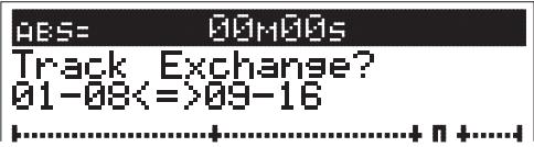
- Selection in 2-track (stereo pair) unit
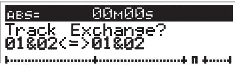
- Selection in single (mono) -track unit
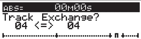
- Press the [HOLD/>] key, then move the cursor to the track to exchange to.
The cursor moves every time the [HOLD/>] key is pressed. The cursor can also be moved using the [REWIND] key or [F FWD] key.
-
Turn the [JOG] dial to select the track to exchange to.
-
Press the [ENTER/YES] key.
"Exchange" appears on the LCD and the exchange process takes place instantaneously.
"Completed!" appears on the LCD when the exchange process is completed.
Then the system returns to the Normal Display.

Tips:
"Select Err!" appears on the LCD and the exchange process is invalidated if the same track is selected for the track to exchange from and track to exchange and [ENTER/YES] key is pressed. (Ex: 03<=>03 and so on)
Mixing
After recording with DIRECT Recording, adjust the play level, equalize the sound or add some effects to the audio sound of track 1-16. This section describes how to adjust the level, PAN, equalizer, effect send level and effect.
Level Adjustment
- Use the Channel Fader to adjust the play level of each channel.
- Use the Master Fader to adjust the stereo OUT level of the output signal of the sounds mixed.
Tips: Master Level
Check the stereo OUT level with the L/R level meter on the LCD. If the output level is too high, the output will distort. Adjust the Master Fader so it does not exceed 0 on the L/R level meter.
PAN Adjustment
If you must edit channel parameters such as setup of PAN or EQ, be sure to check that the "Scene Sequence Mode," explained later, is switched "Off." Should the parameters be edited with this "Scene Sequence Mode" switched "On," the parameters will be returned to their original setting when the VF160EX is operated in PLAY or STOP. Refer to page 66 for "On/off of the Scene Sequence Mode."
1. Press the [PAN] key.
The PAN setup menu appears on the LCD.
"Select CH!" will be flashes.
![FOSTEX VF160EX - Press the [PAN] key. - 1](/content/2025/01/168450/images/7dc6bc64e9720cf56e158dd85acbde14006760e5a3adb88e5320f76e200b9dff.jpg)
2. Press the [CH STATUS/CH SEL] key of the channel intended for PAN adjustment.
The channel selected flashes, then the input signal and the current setting of the channel selected appears on the LCD.
![FOSTEX VF160EX - Press the [CH STATUS/CH SEL] key of the channel intended for PAN adjustment. - 1](/content/2025/01/168450/images/f588d45f1ee695ce2ae33d82687fbb4407bf13dc050285e7aa95f18e4a9555e5.jpg)
3. Turn the [JOG] dial to set the PAN level.
A graphic display of the PAN parameter appears on the LCD in real-time.
- To adjust other channels, press the [CH STATUS/CH SEL] key of that channel, then go to Step 3.
- Press the [EXIT/NO] key when adjustments are completed.
The system returns to the Normal Display.
Equalizer Adjustment
Tips:
For fader-paired channels (set by the "Pair fader setting" menu in the Setup mode), controlling EQ settings for one channel affects both channels simultaneously. See page 146 for details about how to pair faders.
1-1. Press the [HI-G/F/Q] key.
The menu to set the high frequencies of the equalizer appears.
1-2. Press the [MID-G/F/Q] key.
The menu to set the mid frequencies of the equalizer appears.
1-3. Press the [LO-G] key.
The menu to set the low frequencies of the equalizer appears.
![FOSTEX VF160EX - 1-3. Press the [LO-G] key. - 1](/content/2025/01/168450/images/b1477b640c3561e4c2ee8028c5c97ab81e37bfa8e2c30f424bf2ab9bba940dc1.jpg)
2. Press the [CH STATUS/CH SEL] key of the channel intended for equalizer adjustments.
The channel name and current setting of the channel selected appears on the LCD.
![FOSTEX VF160EX - Press the [CH STATUS/CH SEL] key of the channel intended for equalizer adjustments. - 1](/content/2025/01/168450/images/fc1bab4c1170c3ccd0957f1567184f7a694418272dad9e2f25eb124685ed9cc2.jpg)
3. Every time the [HI-G/F/Q] key or [MID-G/F/Q] key is pressed the parameter alternates from G (Gain) -> F (Frequency) -> Q (Characteristic Curve). Select the item to adjust.
Only the G (Gain) can be adjusted for the low frequency equalizer ([LO-G] key). Therefore, the item will not change by pressing the key.
4. Turn the [JOG] dial to modify the parameter of the item to adjust.
The EQ setting graphically appears on the LCD in real-time.
![FOSTEX VF160EX - Turn the [JOG] dial to modify the parameter of the item to adjust. - 1](/content/2025/01/168450/images/0bf030d59f352ed8381438bbc913df96b5a5ca62c3dfc4c47557e1ef6cf8268e.jpg)
- To adjust other items or another frequency range of the equalizer, press again the [HI-G/F/Q] key, [MID-G/F/Q] key or [LO-G] key. Then turn the [JOG] dial to modify the parameter.
- To adjust other channel, press the [CH STATUS/CH SEL] key of that channel.
- When adjustments are completed, press the [EXIT/NO] key. The system returns to the Normal Display.
Effect Send Level Adjustment
Tips:
For fader-paired channels (set by the "Pair fader setting" menu in the Setup mode) controlling the level for one channel affects both channels simultaneously.
See page 146 for details about how to pair faders.
1. Press the [CH PARAM EDIT-EFF1/EFF2] key.
Every time the key is pressed the mode alternates between the EFF1 and EFF2 menu.
![FOSTEX VF160EX - Press the [CH PARAM EDIT-EFF1/EFF2] key. - 1](/content/2025/01/168450/images/198ace1992493c18fcc8230d525959947ec5111eb5e7fc5e25c39abb4a3c6a2b.jpg)
2. Press the [CH STATUS/CH SEL] key of the channel intended to adjust the effect send level.
The channel name and current setting of the channel selected appears on the LCD. Press the [MASTER CH STATUS/CH SEL] key to adjust the master send level.
![FOSTEX VF160EX - Press the [CH STATUS/CH SEL] key of the channel intended to adjust the effect send level. - 1](/content/2025/01/168450/images/6e527da34ca72c3bc21f45b91b421a6513cca1f617401f5a0f6df096ef051fe8.jpg)
-
Turn the [JOG] dial to set the effect send level.
-
To adjust other channels, press the [CH STATUS/CH SEL] key of that channel.
- When adjustments are completed, press the [EXIT/NO] key.
The system returns to the Normal Display.
Modifying Effect Type
1-1. Press the [EFF EDIT-EFF1] key.
The effect 1 selection menu appears along with the currently set effect type.
![FOSTEX VF160EX - 1-1. Press the [EFF EDIT-EFF1] key. - 1](/content/2025/01/168450/images/8f9d02420f2e719de163d9d6b7a49374b89aaaa4839c230ff83b0eab3b5e5c31.jpg)
Example: Display when the [EFF EDIT-EFF1] key is pressed.
1-2. Press the [EFF EDIT-EFF2] key.
The effect 2 selection menu appears along with the currently set effect type.
![FOSTEX VF160EX - 1-2. Press the [EFF EDIT-EFF2] key. - 1](/content/2025/01/168450/images/61367b09a7442ac890a6ef72132322902f481b3a5236cf7ceba0261e0a3c9126.jpg)
Example: Display when the [EFFEDIT-EFF2] key is pressed.
2. Turn the [JOG] dial to select the effect type.
3. Press the [ENTER/YES] key.
The mode switches to the effect selected.
It is possible to adjust the parameters of the effect in this state.
![FOSTEX VF160EX - Press the [ENTER/YES] key. - 1](/content/2025/01/168450/images/31668f4ea54dcd87255be837a034b6fda243bdcc81e7b2e4386dca23e36abb8d.jpg)
The parameter settings alternate every time the [EFF EDIT-EFF1] key or [EFF EDIT-EFF2] key is pressed.
Turn the [JOG] dial to modify the parameters.
Only the effect type is modified here. For more details refer to a later section.
4. When adjustments are completed, press the [EXIT/NO] key several times.
The system returns to the Normal Display.
Mix Down
Create the master tape after adjusting all tracks. Start recording the piece with a master recorder (cassette tape, DAT, MD, etc.). The VF160EX can output S/P DIF (optical) digital signals making it is possible to directly mix down digital signals if the master recorder can input S/P DIF (optical) digital signals.
Tips: Internal Mixdown Mode
The VF160EX features an "Internal mixdown mode".
By using the Internal mixdown mode, you can mix-down up to 16 tracks without using an external master recorder. Also, by using the built-in CD-R/RW drive, you can make your original audio CD from materials mixed-down by the Internal mixdown mode.
See "Advanced Features" on page 79 for the Internal mixdown mode and "Save/load of Song Data" on page 125 for making an audio CD.
Analog Mix Down
- Connect the IN (input jack) of the master recorder with the [ST OUT-L/R] jack of the VF160EX.
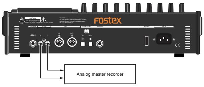
- Adjust the recording level of the master recorder.
- Start recording with the master recorder and then play the song on the VF160EX from the beginning.
- Stop both machines when recording is completed.
Tips: Fade IN/OUT
The VF160EX Master Fader provides a feature to Fade IN (gradually increase the volume) or Fade OUT (gradually decrease the volume) the sound.
Digital Mix Down
-
Connect the digital IN (input jack) of the master recorder with the [DIGITAL/DATA OUT] jack of the VF160EX.
-
Direct connection is possible if the master recorder has a S/P DIF (optical) digital input.
- Use the "Fostex COP-1/96k" for connections if the master recorder has a S/P DIF (coaxial) digital input jack.
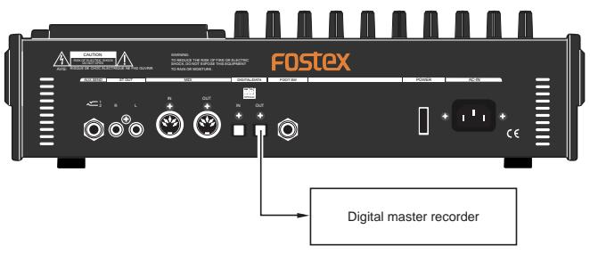
-
Prepare the master recorder to accept digital input.
-
The sampling frequency of the VF160EX is 44.1kHz .
Digital mix down is not possible unless the master recorder can record 44.1kHz digital signals.
-
Generally speaking, the input level of the master recorder is not adjustable for digital input.
-
Fine tune the output level of the VF160EX master fader.
-
In General, the optimal level is when the level meter of the master recorder is 0 at the maximum volume of VF160EX. Note that any level exceeding 0 may cause sound distortion.
- Start recording with the master recorder and then play he song on the VF160EX from the beginning.
- Stop both machines when recording is successfully completed.
Tips: Fade IN/OUT
The VF160EX Master Fader provides the feature to Fade IN (gradually increase the volume) or Fade OUT (gradually decrease the volume) the sound.
Instructions for recording with BUSS RECORD
This section will discuss the basic procedures to REC/PLAY with "BUSS" RECORD, which is another recording option. With DIRECT RECORD, the track recorded was determined according to the input of channel A to H. However, with BUSS RECORD, recording is possible regardless of the channel input. It is also possible to record the input of all 8 channels on 2 tracks with BUSS RECORD. Since the recording process takes place via the mixer, it is possible to apply equalizer and effect sound to the recording.
Note that BUSS RECORD takes place using the REC exclusive "REC BUSS". This "REC BUSS" consists of 2 channels, L and R, therefore, a maximum of 2 tracks can be recorded at the same time.
Description of BUSS RECORD
BUSS RECORD takes place by sending signals processed through the mixer to the "REC BUSS" for recording. Therefore, signals applied with equalization and built-in effect can be recorded (added and recorded).
Here, we will use the channel (ORANGE) with an [INPUT] started with the fader as the source channel. However, channels (GREEN) in which [TRACKS] are started can also be used as a source channel. Ping-pong recording is possible for the source channel recording with the [TRACK] started channel (GREEN).
Note the following precautions for BUSS recording.
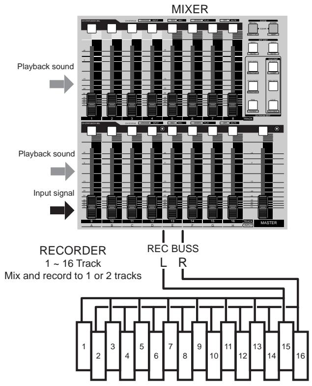
WARNING!
Of the [CH STATUS/CH SEL] key of ch9-16, a channel with an "IN (Input)" which is lit up ORANGE, cannot output sound of the tracks corresponding to ch9 to16, so it is not possible to go to the READY state using the [BUSS-RECTRK] key.
WARNING!
Precautions for when selecting a source channel with the [BUSS-SOURCE] key. (when key is flashing in GREEN)
- A channel in which the [CH STATUS/CH SEL] key light is OFF is selectable.
- The channel selected will either have a flashing ORANGE or GREEN [CH STATUS/CH SEL] key.
- The [CH STATUS/CH SEL] key that is flashing RED is a READY channel (track) and cannot be selected.
WARNING!
Precautions when selecting a REC track with the [BUSS-RECTRK] key. (key is flashing RED)
- A channel in which the [CH STATUS/CH SEL] key light is OFF is selectable.
- The channel selected has a flashing RED [CH STATUS/CH SEL] key.
- The [CH STATUS/CH SEL] key that is flashing ORANGE or GREEN is selected as a source channel, therefore, it cannot be selected.
Here we will record a sound source connected to input H on track 1 of the recorder. Beforehand, set the ch1 to 16 channel faders, master fader and the [TRIM] for A to H to 0. Connect a headphone or speaker to monitor the sound.
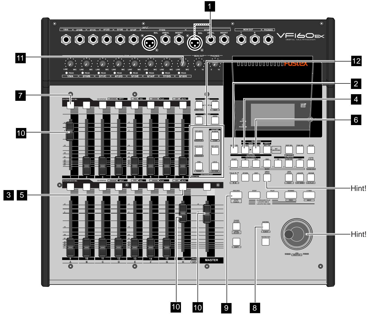
Preparing to Record
1 Connect the sound source to record to [INPUT] jack H.
Press the [INPUT SEL] key (ORANGE: Flashing).
| DES= | #H#DES |
| SELECT | INPUT/TRACK! |
| 1 | 2 | 3 | 4 | 5 | 6 | 7 |
| Q | Q | Q | Q | Q | Q | Q |
| TRK | TRK | TRK | TRK | TRK | TRK | TRK |
| 9 | 10 | 11 | 12 | 13 | 14 | 15 |
| Q | Q | Q | Q | Q | Q | Q |
| TRK | TRK | TRK | TRK | TRK | TRK | TRK |
Press the [CH STATUS/CH SEL] key for ch16 so the key starts "flashing ORANGE (=INPUT)".
The following display appears, and the signals of input H will start for channel 16.
| AES= 33H35 |
| SELECT | INPUT/TRACK! |
| 1 | 2 | 3 | 4 | 5 | 6 | 7 |
| | | | | | |
| TRK | TRK | TRK | TRK | TRK | TRK | TRK |
| 9 | 10 | 11 | 12 | 13 | 14 | 15 |
| | | | | | |
| TRK | TRK | TRK | TRK | TRK | TRK | IN |
Press the [BUSS-SOURCE] key (GREEN: Flashing). The display to select the source channel sent to REC BUSS appears.
| AES= | SCHS35 |
| SELECT | SOURCE! |
| 1 | 2 | 3 | 4 | 5 | 6 | 7 |
| | | | | | |
| 9 | 10 | 11 | 12 | 13 | 14 | 15 |
| | | | | | H |
| | | | | | EFF2 |
Press the [CH STATUS/CH SEL] key of ch16 (ORANGE: Flashing).
The signals of input H started with the fader of ch16 is sent to REC BUSS.
| AES= | CH1285 |
| SELECT | SOURCE! |
| 1 | 2 | 3 | 4 | 5 | 6 | 7 |
| | | | | | |
| 9 | 10 | 11 | 12 | 13 | 14 | 15 |
| | | | | | H |
| | | | | | FF2 |
| | | | | | SRC |
It is possible to apply effect to the input signals by setting EFF1 or EFF2 to the source at the same time. Details are described later.
The channel signal sent to REC BUSS (ch16 in this case) are not directly output from the stereo OUT L/R channels. It will be output from the stereo OUT L/R channels with the track recorded set to the input monitor mode, with later procedures.
6 Press the [BUSS-REC TRK] key (RED: Flashing).
The display to select the REC track appears.
![FOSTEX VF160EX - Press the [BUSS-REC TRK] key (RED: Flashing). - 1](/content/2025/01/168450/images/7274a6318d48bcfb9f98f761c55f07c83790ec6b4f023a57911e4ce120442087.jpg)
When the signals of input H are started with the ch16 fader, it will not be possible to listen to the play sound of the track. Therefore, it is prohibited to put track 16 in the READY (REC) mode.
Press the [CH STATUS/CH SEL] key of ch 1 (RED: Flashing).
Track 1 will go to the "RDY (Ready)" state, and allow the input signal of source channel H to be recorded to track 1.
![FOSTEX VF160EX - Press the [CH STATUS/CH SEL] key of ch 1 (RED: Flashing). - 1](/content/2025/01/168450/images/6660e743f64e915b15cd8c5be75e6090a50efccb232e91b60eb5022e6573ae70.jpg)
Press the [EXIT/NO] key to return to the Normal Display.
Tips: Changing the recording mode
To change the BUSS recording mode to the DIRECT recording mode, press the [DIRECT-REC TRK] key while the tracks to be directly recorded are selected in the step above. "Rec Mode Change!" appears and "Sure?" flashes on the screen.

Pressing the [ENTER/YES] key cancels the selection of tracks for the BUSS recording and changes the display to the track selection screen for the DIRECT recording.
Adjusting the Source Channel
Sound for monitoring purposes can be heard from the headphones or speakers from this point.
Adjust the volume of the monitor sound with the [MON OUT] or [PHONES] knob.
10 Set the ch1 fader, ch16 fader and master fader to "0".
11 Check the sound source and adjust the [TRIM] 8/16/H to an appropriate gain.
The guideline for optimal gain is when the [PEAK] LED is just about to light up when the sound source is turned up to the maximum volume.
12 Accordingly, equalize the signals of ch16 being recorded.
Tips: Equalizing the Source Channel
Press the [HI-G/F/Q] key, [MID-G/F/Q] key or [LO-G] key and switch to channel parameter edit EQ_edit mode to equalize the source channel to record.
Then, press the [CH STATUS/CH SEL] key of ch16 to adjust the sound with a customized equalization (For more details refer to "Adjusting the Equalizer").
13 The final REC level (REC BUSS Master Level) is adjusted according to the following instructions.
After adjusting the master level, press the [EXIT/NO] key to return to the Normal Display.
Tips: Adjusting the REC BUSS Master Level
Turn the [JOG] dial with the system showing the following display to make the final adjustments for the REC BUSS Master Level. Press the [BUSS-RECTRK] key once more to switch to this display from the Normal Display.
The default setting of the REC BUSS Master Level is factory preset to level "80". Use the [JOG] dial to turn the [REC LVL] knob on the LCD as shown below, and adjust the number setting in real-time. The REC BUSS Master Level can also be adjusted (adjustable range: 00-99).
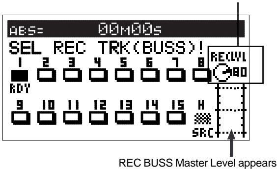
REC BUSS Master Level adjustment icon
Tips: Adjusting the PAN Setting of the Source Channel
When recording on one track with the BUSS RECORD option, the PAN setting of the source channel is either fixed to the left or right.
If the REC track is an odd number, the source channel PAN is fixed all the way to the left. If the REC track is an even number, the source channel PAN is fixed all the way to the right. The source channel PAN can be optionally set ONLY when there are two REC tracks set.
Recording
- Locate the time to start recording on the VF160EX.
- Press the [PLAY] key while the [RECORD] key is depressed to start recording.
The [CH STATUS/CH SEL] key and [RECORD] key of ch1 lights up RED, indicating that recording is taking place.
- Press the [STOP] key when recording is completed, to stop the VF160EX.
"Please Wait" will appear on the LCD, then return to the Normal Display.
These procedures complete the instructions to record to track 1 with the BUSS recording option.
Play
- Locate the time in which recording was started (REC start time).
- Press the [PLAY] key to check the sound recorded.
The ch1 fader can be used to adjust the play level.
The signals recorded on track 1 can be checked.
Tips: UNDO/REDO
By pressing the [UNDO/REDO] key after recording, the recording is undone and the track returns to the pre-REC state where there is no recording (UNDO). By pressing the [UNDO/ REDO] key again, the recording on track is redone to the post-REC state (REDO).
Here we will record all 8 sound sources connected to inputs A to H to tracks 7 and 8 of the recorder.

Preparing to Record
1 Connect to the [INPUT] jack the sound source to record.
Press the [INPUT SEL] key.
Press the [CH STATUS/CH SEL] key of ch9-16 to switch ch 9-16 to "INPUT".
Ch9-16 is ready to start signals of input A to H.
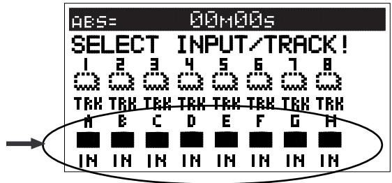
If input signals are started for ch9-16 faders, the play sounds of the corresponding track can no longer be heard and you cannot go to the READY (REC) state.
4 Press the [BUSS-SOURCE] key. (GREEN: Flashing)
Press the [CH STATUS/CH SEL] key of ch 9-16. (ORANGE: Flashing)
Signals of input A to H can now be sent to REC BUSS.
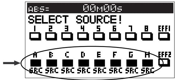
6 Press the [BUSS-REC TRK] key (RED: Flashing).
Press the [CH STATUS/CH SEL] key of ch7 and 8 (RED: Flashing).
Track 7 and 8 will proceed to the "RDY (Ready)" state.
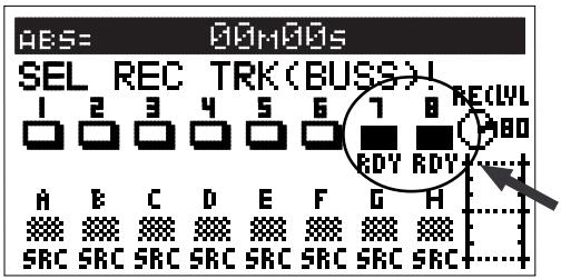
Press the [EXIT/NO] key to return to the Normal Display.
Adjusting the Source Channel
Press the [RECORD] key and set tracks 7 and 8 to the input monitor (RED: Flashing).
As in the earlier case, the monitor sound is output at this stage. Adjust the volume of the monitor sound with the [MON OUT] or [PHONES] knob.
10 Set the ch7&8 fader, ch9-16 fader and master fader to 0.
11 Output the sound of the sound source to record and adjust the [TRIM] to an appropriate gain.
The guideline for optimal gain is when the [PEAK] LED is about to light when the sound source is turned up to the maximum volume.
12 Accordingly, equalize the signals of ch9-16 being recorded and/or adjust the PAN according to the sound source.
Refer to the earlier section for instructions on adjusting the equalizer.
Tips: Adjusting the PAN Setting of the Source Channel It is possible to set the PAN according to the sound source of the source channel when recording to two tracks. Press the [PAN] key to switch to the PAN setting display. Select the channel to adjust the PAN setting with the [CH STATUS/CH SEL] key. Then use the [JOG] dial to optionally set the PAN setting.
13 The final REC Level (REC BUSS Master Level) is adjusted according to the earlier mentioned procedures.
The system is ready to record after you have completed the above procedures.
Record
- Locate the time to record on the VF160EX.
- Press the [PLAY] key while the [RECORD] key is depressed to start recording.
The [CH STATUS/CH SEL] key and the [RECORD] key of ch7& 8 lights up RED, indicating that recording is taking place.
- Press the [STOP] key when the recording is completed, to stop the VF160EX.
"Please Wait" appears on the LCD and then returns to the Normal Display.
This completes recording the sound source of inputs A to H on tracks 7 and 8.
Tips: UNDO/REDO
By pressing the [UNDO/REDO] key after recording, the recording is undone and the track returns to the preREC state where there is no recording (UNDO). By pressing the [UNDO/REDO] key again, the recording on two tracks are redone to the post-REC state (REDO). The UNDO/REDO feature is available for all recordings.
Play
- Locate the time in which recording was started (REC start time).
- Press the [PLAY] key to play the VF160EX.
Adjust the play level of tracks 7 and 8 with the ch7 & 8 faders to check (listen to) the sound recorded.
Tips: Applying an Effect on the Source Channel
It is possible to apply effect sound on the source channel during BUSS RECORD.
1. EFF1 or EFF2 can also be selected at the same time for the source channel from the display (appears by pressing the [BUSS SOURCE] key) to select the source channel, as described earlier.
The following figure shows the example where input H and EFF1 are both applied to the source channel, and allows EFFECT 1 to be applied to the input H signals.
![FOSTEX VF160EX - EFF1 or EFF2 can also be selected at the same time for the source channel from the display (appears by pressing the [BUSS SOURCE] key) to select the source channel, as described earlier. - 1](/content/2025/01/168450/images/a9a5d676077d18acd07e667171908600037c5d907838d8161b8030bd7e2df55c.jpg)
2. Press the [CH PARAM EDIT-EFF1/EFF2] key to adjust the send level of effect 1.
Press the [CH STATUS/CH SEL] key of ch16, select input H and use the [JOG] dial to adjust the send level of input H. The signal level adjusted here is sent to effect 1. To adjust the master send level, use the [CH STATUS/ CH SEL] key of the master channel to select the master send level and adjust it with the [JOG] dial.
![FOSTEX VF160EX - Press the [CH PARAM EDIT-EFF1/EFF2] key to adjust the send level of effect 1. - 1](/content/2025/01/168450/images/edde47202f0869a08a98e4f3eb1b574605b82e09cd419c616efcfa114720bbf1.jpg)
3. Press the [EFF EDIT-EFF1] key, select the effect type desired and then edit the effect parameter.
It is possible to apply the selected effect on the sound recorded.
![FOSTEX VF160EX - Press the [EFF EDIT-EFF1] key, select the effect type desired and then edit the effect parameter. - 1](/content/2025/01/168450/images/286de1723481d5d8ed438d01df646da29369b66440273c6cd03c249523bb025f.jpg)
Tips:
It is possible to apply different effects (EFF1/EFF2) on multiple source channels by individually tuning the signal level sent to EFFECT1/EFFECT2, upon adjusting the above effect send level.
Chapter 3 Advanced mixer operations
This section describes practical operations of the mixer including functions that are not described in "Basic operations" as well as detailed information about settings.
Initial condition when the power is turned on
When you turn the power on, the VF160EX shows the start-up display ("FOSTEX" -> "Initial.." -> "Current DR", "IDE" -> "FormatType" ["Standard" or "Quick"]), and then becomes ready. In this condition, only the [CH STATUS/CH SEL] key, [STOP] key, [EFF 1] key, and [EFF 2] key light on the panel, while the display looks as shown below.
In this manual, we refer to this display as the "Normal display", in which you can see the current recorder position is at the beginning (ABS 00M 00S) of the program 1 (P01).
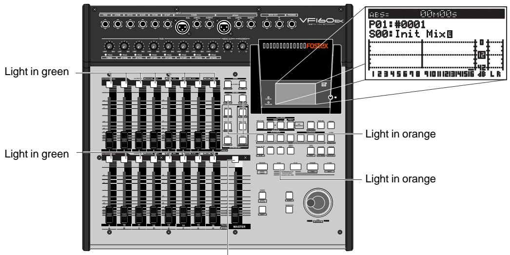
Light in green
Operation while the Normal display is shown
Fader
The fader for each channel (1 through 16) controls the level of TRACK or INPUT signal fed to the stereo output or the Rec busses. If two adjacent channels are fader-paired, the fader on the odd channel controls both channel levels. The master fader controls the total level of the stereo output busses.
Channel mute and Solo function
In the Normal display, pressing a [CH STATUS/CH SEL] key mutes the corresponding channel. The [CH STATUS/CH SEL] key for the muted channel is unlit.
Pressing the key again releases muting and lights the key. If two adjacent channels are fader-paired, pressing one of the [CH STATUS/CH SEL] key for the two channels mutes both channels.
Also, pressing the [CH STATUS/CH SEL] key while holding down the [SHIFT] key alternates on and off of the solo for that channel.
Master channel mute
While the Normal display is shown, pressing a [CH STATUS/CH SEL] key for the master channel mutes the stereo output signals. The [CH STATUS/CH SEL] key of the master channel is unlit. Pressing the key again releases muting and lights the key.
In the normal display mode, every time the [INPUT SEL] key is pressed with the [SHIFT] key depressed down, the Adat Mixer Mode will alternately switch on/off. The input monitor (READY) of all tracks will simultaneously switch on/off. The Adat Mixer Mode is a convenient for example when recording by connecting a VF160EX to a personal computer installed with an adat optical sound card. In this way, the VF160EX can be used in four roles: As an AUDIO track monitor mixer (using faders of ch1-8). As an AD (the level adjusted by [TRIM] is possible in low latency monitoring).
As a monitor mixer (using faders ch9-16).
As a 16MTR for simultaneous recording of all of these roles. Refer to page 95.
- To use the VF160EX in the Adat Mixer Mode, the SETUP mode digital input/digital output setting must be first set to "adat."
- Tracks set to "IN (Input)" by "INPUT SEL" cannot be changed to READY.
- This function is effective only for executing DIRECT recording and will not function for BUSS recording.
If you execute the above while in BUSS recording, the VF160EX will want to select a different recording mode. "Rec Mode Change!" will be displayed and "Sure?" will flash. At this point, if the [ENTER/YES] key is pressed, simultaneous with change in the recording mode, the Adat Mixer Mode will switch on. If the [EXIT/NO] key is pressed, the BUSS recording mode can be continued.
Channel Parameter Edit
You can edit the various parameter settings such as pan and equalizers for channels 1 through 16 and the master channel. We refer this type of editing as "Channel parameter edit". There are several channel parameter edit keys on the top panel (as shown below) and pressing the dedicated key for the parameter you want to edit brings up the corresponding edit screen. Some keys also handle the second parameter (labeled under the key) and you can bring up the corresponding edit screen by pressing the key while holding down the [SHIFT] key. You can view and/or edit the following parameters.
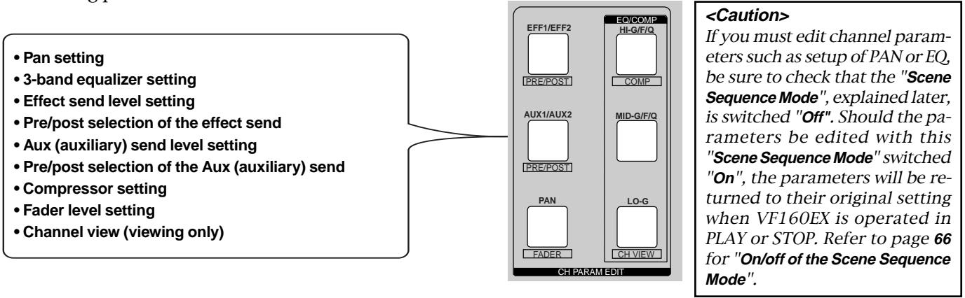
If a channel whose source is set to INPUT via the INPUT SEL setting is selected as the edit channel, the channel name is shown as below. In the following example, channel 9 which is set to INPUT, is selected as the edit channel.
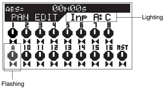
Adjusting Pan
You can adjust the pan (or balance) of each input channel signal fed to the stereo outputs, as well as fed to the Rec buss outputs. The panpot for master channel controls the L/R level balance of the stereo outputs.
1. Press the [PAN] key.
All channel settings are shown on the screen. The first time you bring up the channel parameter edit screen, the message prompting to select a channel ("Select CH!") flashes, as well as all the CH STATUS/CH SEL indicators on the panel flash. From the second time on, the previously selected channel is selected and ready to be edited when bringing up the screen (as shown in the drawing of step 2 below).
![FOSTEX VF160EX - Press the [PAN] key. - 1](/content/2025/01/168450/images/379cc0581e95451d113be83b4ea9349223a9404428db795ccfe6cfce2223cb01.jpg)
2. Press the [CH STATUS/CH SEL] key of the desired channel.
The current settings are shown, together with the selected channel name. The icon for the selected channel is flashing, indicating that you can edit it.
![FOSTEX VF160EX - Press the [CH STATUS/CH SEL] key of the desired channel. - 1](/content/2025/01/168450/images/4e2beb3403cf45e7e7cbd25ecf58839b4656751a1b3c4454939933054edcc95d.jpg)
3. Use the [JOG] dial to adjust panning.
Rotating the [JOG] dial to the left or right moves the pan position to the left or right respectively. The following show examples of the pan settings.
| Pan position: center | Pan position: hard left | Pan position: hard right |
| •Controllable channels
Channels 1 through 16 and the master channel
•Available values
L10 (hard left) through C (center) to R10 (hard right) (the default setting: "C" for all channels)
* Values are displayed between L10 and R10 in 21 steps but the actual pan setting is changed smoothly and continuously as rotating the [JOG] dial. |
4. To set another channel's pan, repeat steps 2 and 3 above.
5. After completing pan editing, press the [EXIT/NO] key.
The VF160EX exits the channel edit mode and the display returns to the Normal display.
Adjusting EQ
The VF160EX provides a 3-band equalizer section including HI, MID and LO bands. You can control G (gain), F (frequency) and Q for HI and MID equalizers, while only G (gain) for LO.
If channels 13-14 or 15-16 are specified as the compressor channels via "Setting the compressor channels" in the Setup mode, you cannot apply the equalizer to those channels. If you press a [CH STATUS/CH SEL] key of the compressor channel, a warning message ("Can't Select!") flashes and the operation is cancelled. In the screen example shown below, the compressor is applied to channels 13-14.
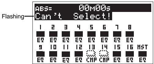
1. Press the [HI-G/F/Q] (or [MID-G/F/Q] or [LO-G]) key.
The first time you bring up the channel parameter edit screen, the message prompting to select a channel ("Select CH!") flashes, as well as all the CH STATUS/CH SEL indicators on the panel flash.
From the second time on, the previously selected channel is selected and ready to be edited when bringing up the screen as shown in the drawing of step 2 below.
![FOSTEX VF160EX - Press the [HI-G/F/Q] (or [MID-G/F/Q] or [LO-G]) key. - 1](/content/2025/01/168450/images/99e7eb29e500449475c4c607705478ddfdf73bf92d9218f20747bb7f7c97f2d8.jpg)
* CH STATUS/CH SEL indicators for the compressor channels do not flash.
2. Press the [CH STATUS/CH SEL] key of the desired channel.
The current settings are shown, together with the selected channel name. The gain value flashes, indicating that you can edit it.
![FOSTEX VF160EX - Press the [CH STATUS/CH SEL] key of the desired channel. - 1](/content/2025/01/168450/images/e08b0ade83861a9d369b28b6f29a08b911c9bcb5925e9b30e02dfa2008da8418.jpg)
If two adjacent channels are fader-paired, pressing one of the [CH STATUS/CH SEL] keys for these channels selects both channels and you can adjust EQ for both channels simultaneously.
See page 146 for details about how to pair faders of adjacent two channels.
3. Use the [HI-G/F/H] (or [MID-G/F/Q] or [LO-G]) or [HOLD/>] key to select a parameter.
Each time you press the key, the flashing parameter (to be edited) changes in the following order.
G -> F -> Q -> ON -> G ....(When setting the LO equalizer, the flashing parameter changes between G and ON.)
4. Use the [JOG] dial to select the desired value.
The following shows an example for editing the HI EQ's gain. The curve corresponding to the setting value is graphically shown. Setting this directly affects the sound.
![FOSTEX VF160EX - Use the [JOG] dial to select the desired value. - 1](/content/2025/01/168450/images/012d86bd00b8d9a184c4681cd861ba126d62de5ac7fec686de7d1c0a407f72f5.jpg)
By rotating the [JOG] dial, you can set each parameter to the desired value within the range shown below.
- Controllable channels:
Channels 1 through 16 and the master channel. You cannot equalize channels 13-14 or 15-16 if they are set as the compressor channels via the Setup mode.
Available parameters and setting ranges:
(HI-G/F/H)
G (gain): -18 dB to FLAT to +18 dB (default: FLAT)
F (frequency): 500Hz to 20.2kHz (default: 4.00 kHz)
Q: LPF, H-S, 0.1 to 20 (default: H-S) ON/OFF: ON or OFF (default: ON)
(MID-G/F/H)
G (gain): -18 dB to FLAT to +18 dB (default: FLAT)
F (frequency): 500Hz to 20.2kHz (default: 1.00 kHz)
Q: LPF, H-S, 0.1 to 20 (default: 1.0) ON/OFF: ON or OFF (default: ON)
(LO-G)
G (gain): -18 dB to FLAT to +18 dB (default: FLAT)
F (frequency): fixed to 400Hz (effective frequency: 100Hz )
Q: fixed to L-S
ON/OFF: ON or OFF (default: ON)
LPF: low pass filter
^H - S : hi-shelving
*L-S: low-shelving
- To edit the EQ for another channel, repeat step 1 through 3.
5. After completing EQ editing, press the [EXIT/NO] key.
The VF160EX exits the EQedit mode and the display returns to the Normal display.
Controlling Effect send level
You can control send levels of channels 1 through 16 (pre- or post-fader) to the two internal A.S.P. effect processors. The master channel controls the effect send master level.
1. Press the [EFF1/EFF2] key to bring up the effect send level screen.
Each time you press the [EFF1/EFF2] key, the EFF1 send level and EFF2 send level screens alternate.
The first time you bring up the channel parameter edit screen, the message prompting to select a channel ("Select CH!") flashes, as well as all the CH STATUS/CH SEL indicators on the panel flash.
From the second time on, the previously selected channel is selected and ready to be edited when bringing up the screen (as shown in the drawing of step 2 below).
![FOSTEX VF160EX - Press the [EFF1/EFF2] key to bring up the effect send level screen. - 1](/content/2025/01/168450/images/48d6e230d66665cbcbf752148dab4cd25c03ef7673124658b2b246313875d4ee.jpg)
2. Press the [CH STATUS/CH SEL] key of the desired channel.
The current settings are shown, together with the selected channel name. The icon for the selected channel is flashing, indicating that you can edit it.
![FOSTEX VF160EX - Press the [CH STATUS/CH SEL] key of the desired channel. - 1](/content/2025/01/168450/images/7b45c23511e5a24f3f0afb51f8eb0249da3f2a2f0d1e4872e69368d2936ca873.jpg)
If two adjacent channels are fader-paired, pressing one of the [CH STATUS/CH SEL] keys for these channels selects both channels and you can adjust levels for both channels simultaneously.
See page 146 for details about how to pair faders of adjacent two channels.
3. Use the [JOG] dial to control the send level.
The numeric value and the marker position of the rotary pot icon change according to the current level.
-Controllable channels:
Channels 1 through 16 and the master level.
Available values:
00 to 99 (dB), (the default setting: channels 1 through 16: "00", master level: "80")
- To set another channel's send level, repeat steps 2 and 3 above.
- After completing send level editing, press the [EXIT/NO] key.
The VF160EX exits the channel edit mode and the display returns to the Normal display.
Selecting pre/post of Effect sends
You can select whether the pre-fader or post-fader signal is sent from each channel (1 to 16) to the effect processor.
If you select "Post", the signal adjusted by the channel fader is sent to the effect processor is also lowered. If you select "Pre", the signal that is not affected by the channel fader is sent to the effect processor, so even if you lower the channel fader to minimum, the signal can be sent to the effect processor.
1. Press the [EFF1/EFF2] key while holding down the [SHIFT] key.
Each time you press the [EFF1/EFF2] key while holding down the [SHIFT] key, the pre/post selection screens for EFF1 and EFF2 alternate.
The first time you bring up the channel parameter edit screen, the message prompting to select a channel ("Select CH!") flashes, as well as all the CH STATUS/CH SEL indicators on the panel flash.
From the second time on, the previously selected channel is selected and ready to be edited when bringing up the screen (as shown in the drawing of step 2 below).
![FOSTEX VF160EX - Press the [EFF1/EFF2] key while holding down the [SHIFT] key. - 1](/content/2025/01/168450/images/3c0409ec8e5b5acecae72244ab9e4674862f19afac2971a177c4890b2d5349ca.jpg)
2. Press the [CH STATUS/CH SEL] key of the desired channel.
The current settings are shown, together with the selected channel name. The icon for the selected channel is flashing, indicating that you can edit it.
![FOSTEX VF160EX - Press the [CH STATUS/CH SEL] key of the desired channel. - 1](/content/2025/01/168450/images/51f56dc6109f4c219a3bbdba5ecc1c2577206d9512e89e2ced57957f56ac7736.jpg)
If two adjacent channels are fader-paired, pressing one of the [CH STATUS/CH SEL] keys for these channels selects both channels and you can set PRE or POST for both channels simultaneously. See page 146 for details about how to pair faders of adjacent two channels.
3. Use the [JOG] dial to switch the selection.
The icon color and label changes according to the selection, as shown below.
| PRE | The pre-fader signal is sent to the effect processor. |
| PST | The post-fader signal is sent to the effect processor. |
| •Controllable channels: Channels 1 through 16.
•Available options: PRE or PST (post), (default: all channels: “PST”) |
- To set another channel's pre/post selection, repeat steps 2 and 3 above.
5. After completing the pre/post selection, press the [EXIT/NO] key.
The VF160EX exits the channel edit mode and the display returns to the Normal display.
Controlling AUX SEND level
You can control send levels of channels 1 through 16 (pre- or post-fader) from the [AUX SEND] jack on the rear panel. The master channel controls the AUX send master level.
1. Press the [AUX1/AUX2] key to bring up the AUX send level screen.
Each time you press the [AUX1/AUX2] key, the AUX1 send level and AUX2 send level screens alternate.
The first time you bring up the channel parameter edit screen, the message prompting to select a channel ("Select CH!") flashes, as well as all the CH STATUS/CH SEL indicators on the panel flash. From the second time on, the previously selected channel is selected and ready to be edited when bringing up the screen (as shown in the drawing of step 2 below).
![FOSTEX VF160EX - Press the [AUX1/AUX2] key to bring up the AUX send level screen. - 1](/content/2025/01/168450/images/2796706d8221fb0a4c9f3e446415f7623bc6ffe2cf80e5b10073ab25bb48d383.jpg)
2. Press the [CH STATUS/CH SEL] key of the desired channel.
The current settings are shown, together with the selected channel name. The icon for the selected channel is flashing, indicating that you can edit it.
![FOSTEX VF160EX - Press the [CH STATUS/CH SEL] key of the desired channel. - 1](/content/2025/01/168450/images/13c315af39fe3ff408b7060a9f14f1dfd2abbc93f4a3df3fa18475768c01d6f1.jpg)
If two adjacent channels are fader-paired, pressing one of the [CH STATUS/CH SEL] keys for these channels selects both channels and you can adjust levels for both channels simultaneously. See page 146 for details about how to pair faders of adjacent two channels.
3. Use the [JOG] dial to control the send level.
The numeric value and the marker position of the rotary pot icon change according to the current level. ("80", the default value, is the reference level.)
-Controllable channels:
Channels 1 through 16 and the master level.
Available values:
00 to 99 (dB), (the default setting: channels 1 through 16: “00”, master level: “80”)
4. To set another channel's send level, repeat steps 2 and 3 above.
5. After completing send level editing, press the [EXIT/NO] key.
The VF160EX exits the channel edit mode and the display returns to the Normal display.
Selecting pre/post of AUX sends
You can select whether the pre-fader or post-fader signal is fed from each channel (1 to 16) to the [AUX SEND] jack. If you select "Post", the signal adjusted by the channel fader is sent to the effect processor, so if you lower the channel fader, the signal sent to the effect processor is also lowered.
If you select "Pre", the signal that is not affected by the channel fader is sent to the effect processor, so even if you lower the channel fader to minimum, the signal can be sent to the effect processor.
1. Press the [AUX1/AUX2] key while holding down the [SHIFT] key to bring up the pre/post selection screen. Each time you press the [AUX1/AUX2] key while holding down the [SHIFT] key, the pre/post selection screens for EFF1 and EFF2 alternate. The first time you bring up the channel parameter edit screen, the message prompting to select a channel ("Select CH!") flashes, as well as all the CH STATUS/CH SEL indicators on the panel flash. From the second time on, the previously selected channel is selected and ready to be edited when bringing up the screen (as shown in the drawing of step 2 below).
![FOSTEX VF160EX - Press the [AUX1/AUX2] key while holding down the [SHIFT] key to bring up the pre/post selection screen. Each time you press the [AUX1/AUX2] key while holding down the [SHIFT] key, the pre/post selection screens for EFF1 and EFF2 alternate. The first time you bring up the channel parameter edit screen, the message prompting to select a channel ("Select CH!") flashes, as well as all the CH STATUS/CH SEL indicators on the panel flash. From the second time on, the previously selected channel is selected and ready to be edited when bringing up the screen (as shown in the drawing of step 2 below). - 1](/content/2025/01/168450/images/d21dbaefd532b99ae5111c2a43c239465d1f21abd795e887393198d6308dd818.jpg)
2. Press the [CH STATUS/CH SEL] key of the desired channel.
The current settings are shown, together with the selected channel name. The icon for the selected channel is flashing, indicating that you can edit it.
![FOSTEX VF160EX - Press the [CH STATUS/CH SEL] key of the desired channel. - 1](/content/2025/01/168450/images/32112689507f4a0346c2ff8f5c8af92f8eeef1fd1ac5ebbc71a4298e0fb3bea5.jpg)
If two adjacent channels are fader-paired, pressing one of the [CH STATUS/CH SEL] keys for these channels selects both channels and you can set PRE or POST for both channels simultaneously. See page 146 for details about how to pair faders of adjacent two channels.
3. Use the [JOG] dial to switch the selection.
The icon color and label changes according to the selection, as shown below.
| PRE | The pre-fader signal is fed to the AUX SEND jack. |
| PST | The post-fader signal is fed to the AUX SEND jack. |
| •Controllable channels:
Channels 1 through 16.
•Available options:
PRE or PST (post) (default: all channels: “PST”) |
4. To set another channel's pre/post selection, repeat steps 2 and 3 above.
5. After completing the pre/post selection, press the [EXIT/ NO] key.
The VF160EX exits the channel edit mode and the display returns to the Normal display.
Controlling fader levels
You can control fader levels for channels 1 through 16 and the master channel while viewing the numeric values.
1. Press the [PAN] key while holding down the [SHIFT] key.
The current fader positions for all channels are shown both graphically and numerically.
![FOSTEX VF160EX - Press the [PAN] key while holding down the [SHIFT] key. - 1](/content/2025/01/168450/images/1b1c6f84a7565b17dbd9fd580c43da5269f7ff26fa2166e98eebdbdb66b93679.jpg)
2. Use the desired fader to control the channel level.
The fader position shown on the screen (both graphically and numerically) changes according to the actual fader position in real-time.
- Controllable channels:
Channels 1 through 16 and the master channel
Available values:
00 to 99 ( The value is displayed by a whole number but the actual signal level is changed smoothly and continuously.)
If two adjacent channels are fader-paired, the fader for the odd channel controls levels for both channels simultaneously. See page 146 for details about how to pair faders of adjacent two channels.
3. After completing fader level setting, press the [EXIT/NO] key.
The VF160EX exits the channel edit mode and the display returns to the Normal display.
Setting the compressor
You can apply the built-in compressor only to the channels selected by "Compressor channel setting" in the Setup mode.
The compressor is used to compress the dynamic range of the input signal. If the input signal exceeds a given level (the threshold level), the gain is decreased as the input signal level increases, to reduce the dynamic range of the output signal.
You can apply the built-in compressor only to channels 13 through 16 and the master channel. You can select the channels to be compressed between channel 13-14 and 15-16 by using "Compressor channel setting" in the Setup mode. You can apply the compressor to the master channel anytime regardless of the compressor channel setting. See the detailed information on page 148 for the Setup mode.
You cannot apply the equalizer to the input channels that the compressor is applied to. However, you can apply both the equalizer and compressor to the master channel.
The following operations are assumed that the compressor is applied to channels 13 and 14.
1. Press the [HI-G/F/Q] key while holding down the [SHIFT] key.
The compressor setting screen appears.
The message prompting to select a channel ("Select CH!") flashes, as well as the CH STATUS/CH SEL indicators for the master channel and input channels (13-14 or 15-16) to which the compressor is applied flash.
![FOSTEX VF160EX - Press the [HI-G/F/Q] key while holding down the [SHIFT] key. - 1](/content/2025/01/168450/images/bf865aaed3908d354480a7c50da842808d4db68ddfc8d7ac8b691701a481b440.jpg)
2. Press the [CH STATUS/CH SEL] key of the desired channel.
You can now edit parameters of the compressor for the channel.
![FOSTEX VF160EX - Press the [CH STATUS/CH SEL] key of the desired channel. - 1](/content/2025/01/168450/images/ae9f70a7439e0ab38d90ddedb249ecda279125d401e1771475f6df2d7f3e3406.jpg)
If two adjacent channels are fader-paired, pressing one of the [CH STATUS/CH SEL] keys for these channels applies the compressors to both channels simultaneously. See page 146 for details about how to pair faders of adjacent two channels.
3. Press the [HI-G/F/Q] key to select the desired parameter, and enter the desired value using the [JOG] dial.
Each time you press the [HI-G/F/Q] key while holding down the [SHIFT] key, the parameters to be edited are cycled between "THSHD" (threshold level), "RATIO", "ATTACK" (attack time), "GAIN" and "ON/OFF" (compressor on/off). For each parameter, rotating the [JOG] dial can set the following values.
Channels to be selected
Channels 13-14, 15-16 and the master channel
Available values
Threshold level: 0.0 dB to -50.0 dB (in 0.5 dB increments)
(The default setting: 13-14/15-16->20dB, master:-->25dB)
Ratio: - :1 20:1, 10:1, 8:1, 6:1, 5:1, 4:1, 3.5:1, 3:1, 2.5:1, 2:1, 1.7:1, 1.5:1, 1.3:1, 1.1:1, 1:1 (The default settings: 13-14/15-16 -> 10:1, master -> 4:1)
Attack time: 5 ms to 75 ms (in 1 ms increments)
(The default settings: 13-14/15-16 -> "60ms", master -> "8ms")
Gain: 0.0 dB to +18.0 dB (in 0.5 dB increments)
(The default settings: 13-14/15-16/master -> 0.0 dB.)
Compressor on/off: On, Off (The default is "Off.")
4. After completing the parameter setting, press the [EXIT/NO] key.
The VF160EX exits the channel edit mode and the display returns to the Normal display.
If you try to select a channel to which the compressor cannot be applied, a warning message ("Can't Select!") will flash and the operation will be cancelled.
The following screen shows that you can apply the compressor to channels 13-14 and the master channel.
![FOSTEX VF160EX - After completing the parameter setting, press the [EXIT/NO] key. - 1](/content/2025/01/168450/images/9771b2fe24ba865106c1f03d993bd3958dabf223a8eb89940c58cb44eb4a9e7c.jpg)
Channel view
You can see the current setting information for channels 1 through 16 via the Channel view screen.
1) Channel on/off
2) Fader levels
3) Send levels and pre/post selections for EFF1, EFF2, AUX1 and AUX2.
4) Pan positions
5) Signal destination (stereo busses or Rec busses)
1. Press the [LO-G] key while holding down the [SHIFT] key.
The channel view screen appears.
The first time you bring up the channel parameter edit screen, the message prompting to select a channel ("Select CH!") flashes, as well as all the CH STATUS/CH SEL indicators on the panel flash.
From the second time on, the screen shows the status information of the previously selected channel when bringing up the screen (as shown in the drawing of step 2 below).
![FOSTEX VF160EX - Press the [LO-G] key while holding down the [SHIFT] key. - 1](/content/2025/01/168450/images/826263950564836b4ca513bc2fda44a392421738a4a77daa71b491d5b4026739.jpg)
2. Press the [CH STATUS/CH SEL] key of the desired channel.
The current setting information is shown, together with the channel name.
![FOSTEX VF160EX - Press the [CH STATUS/CH SEL] key of the desired channel. - 1](/content/2025/01/168450/images/2cc09210efa6e49669d6c41cd25fb0d0584eb70dc15dab46b79ff72193b4d316.jpg)
If two adjacent channels are fader-paired, when pressing the [CH STATUS/CH SEL] key for the even channel, the fader icon in the figure shown in step 3 above is shown in dotted line.
See page 146 for details about how to pair faders of adjacent two channels.
The screen example above shows the following status.
| 1 | Channel 1 is currently selected. |
| 2 | The channel is on. |
| 3 | The channel fader is set to "00" (−∞). |
| 4 | The pan is in the center position. |
| 5 | The signal is fed to ST OUT (L/R). |
| 6 | The post-fader signal of the selected channel is fed to EFF1, EFF2, AUX1 and AUX2 at level 80. |
| |9 | |
3. To turn off the channel view screen, press the [EXIT/NO] key.
The VF160EX exits the channel edit mode and the display returns to the Normal display.
Effect Edit Mode
The VF160EX offers high quality ambient effects by employing the A. S. P. (Fostex Advanced Signal Processing Technology), which is exclusively developed by Fostex. With the A. S. P., you can obtain an incomparably clean and high density Hall Reverb, overwhelmingly clear Room Reverb and wonderfully hi-fidelity Plate Reverb. In addition to these typical Reverbs, the VF160EX provides not only various practical algorithms such as Delay, Chorus, Flanger and Pitch Bend, but some combinations of these are also available, e.g., Delay+Reverb.

* A. S. P. (Fostex Advanced Signal Processing Technology)
The A. S. P. is an exclusive new digital effect processing technology designed by Fostex. This method extracts maximum efficiency from the limited DSP power. It achieves an overwhelmingly high density Early Reflection sound and wonderfully smooth High Dump response through the H. F. A. (Harmonic Feedback Algorithm). Also, it carries out an elaborate reverb simulation with clear sounds through the H. D. L. P. (Hi-Density Logarithmic Processing), which eliminates the mutual interference between the numerous integrated delay modules and reduce the impurity and girt of the sound.
* H. F. A. (Harmonic Feedback Algorithm)
There is one of indispensable elements in the natural echo called "Early Reflection Sound," which is usually sacrificed in commercial reverb products in order to reduce costs. (In practice, the Early Reflection Sound means the very first reverberated sound that bounces back from walls, floors and ceilings of concert halls). The entire reverb sound quality depends on this Early Reflection Sound and how closely it can resemble the real echo. The H. F. A. is an algorithm that enables the effect unit to reproduce a clear and natural Early Reflection Sound by applying an ideal harmonic feedback to each delay module.
* H. D. L. P. (Hi-Density Logarithmic Processing)
The reverb sounds consist of lots of small delay elements combined in a complex way, which are produced by many delay modules inside the effect unit. In order to obtain smooth and comfortable reverb sounds, it is very important to efficiently organize the relationship between each delay module and minimize negative mutual interference. The H. D. L. P. is a technology which applies efficient logarithmic processing to each delay module, so that they can work in the most efficient way in order to eliminate harmful reverb elements and roughness. This makes it possible to establish high density and transparent sounds.
Before the operation, we will briefly discuss the effect functions here such as Reverb, Delay, Chorus, and Flanger, which are integrated in the VF160EX.
Reverb
The so called Reverb effect consists of various reflection sounds mixed together. For example, when you clap your hands in a tunnel, you will hear the sound linger even after you stop clapping your hands. This is the Reverb.
The sounds we normally hear in daily life have three types of sounds mixed together, i.e., "Direct sound," "Early Reflection sound" and "Late Reflection sound." The Direct sound means the sound directly reaches the ears from the sound source. The Early Reflection sound means the sound that comes after the Direct sound and has rebound off the wall of the tunnel up to a few times. The Late Reflection sound means that the sound rebounds many times long after the Direct sound has disappeared. Our ears normally hear the "Direct sound" - "Early Reflection sound" - "Late Reflection sound" in the order.
Delay
This is the effect to added a delayed sound to the original sound. You can obtain a richer sound or completely change the original source sound by using the Delay.
Chorus
This makes the one original sound appear to have many sources. The Chorus is used to widen or thicken the original sound.
Flanger
The Flanger is one of applications of the Delay. This is used to create a sound like a jet airplane ascending or descending.
About the effect types
The VF160EX contains two independent DSP multi-effect units; EFF 1 and EFF 2.
A variety of effect types are preset for each effect unit. By selecting a suitable effect type, you can process the sound as you wish. You can also edit the parameters of the selected effect type to create your own effect sounds. The following 28 effect types are preset for EFF 1. The 38 effect types shown on the next page are provided for EFF 2, and these include the same 28 effect types as EFF 1.
Effect types preset for EFF 1
| Name | Parameter type | Explanation |
| L01 | Norm HALL | REVERB | Standard hall reverb; detailed and transparent, with a moderate amount of early reflections. |
| L02 | Pres HALL | REVERB | Hall reverb with presence and definition. |
| L03 | Wet HALL | REVERB | Hall reverb with restrained high-frequency and a refreshing atmosphere. |
| L04 | NoER HALL | REVERB | All-purpose hall reverb with no early reflections, and even decay of all frequencies. |
| L05 | Lo-F HALL | REVERB | Hall reverb with lingering low-frequency reverberation. |
| L06 | STADIUM | REVERB | Stadium reverb characterized by long early reflections. |
| L07 | AUDITRIUM | REVERB | Reverb simulating an auditorium with suppressed reverberation. |
| L08 | HALL WAY | REVERB | Reverb with a long pre-delay, creating the impression of an extended space. |
| L09 | Norm ROOM | REVERB | Room reverb simulating a moderate space with some sparkle. |
| L10 | Dead ROOM | REVERB | Room reverb simulating a narrow and dead room. Adding a slight amount will give warmth to the sound. |
| L11 | Pres ROOM | REVERB | All-purpose room reverb, with good definition and few early reflections. |
| L12 | DrumBOOTH | REVERB | Room reverb simulating a drum booth. |
| L13 | GARAGE | REVERB | Room reverb simulating a narrow and live space like a garage, with crisp presence. |
| L14 | NormPLATE | REVERB | Modern-sounding plate reverb with wide bandwidth. |
| L15 | Old PLATE | REVERB | Standard plate reverb with the character of older plate units. |
| L16 | PresPLATE | REVERB | Plate reverb with good definition and extended high-frequencies. |
| L17 | Wet PLATE | REVERB | Plate reverb with a gentle character. |
| L18 | DigiPLATE | REVERB | Plate reverb that emphasizes a digital character, with metallic early reflections. |
| L19 | NormVOCAL | REVERB | All-purpose hall reverb with no early reflections, and uniform decay at all frequencies. |
| L20 | PresVOCAL | REVERB | Short reverberation with extended high frequency is added to the early reflections of an ideal vocal booth. Since this adds sparkle to the sound, it is effective when you wish to bring the vocal to the forefront. |
| L21 | SoloVOCAL | REVERB | Plate-like reverb is added to a spacious short delay. This blends well with any genre of music. |
| L22 | Arena VOC | REVERB | Gentle reverb is added to spacious stadium-type early reflections. |
| L23 | Arena CHO | REVERB | Short reverb with extended high frequency is added to spacious stadium-type early reflections. Effective on chorus parts. |
| L24 | KARAOKE | REVERB | All-purpose reverb (karaoke style) that makes any vocal sound professional. |
| L25 | MnDL-HALL | DLY+REVERB | A combined effect of mono delay and hall reverb. |
| L26 | MnDL-PLT | DLY+REVERB | A combined effect of mono delay and plate reverb. |
| L27 | PnDL-HALL | DLY+REVERB | A combined effect of panning delay and hall reverb. |
| L28 | PnDL-PLT | DLY+REVERB | A combined effect of panning delay and plate reverb. |
Effect types preset for EFF 2
| Name | Parameter type | Explanation |
| L01~L28 | 1~28 are the same effect types as the EFF 1 presets listed on the preceding page. (For details refer to the preceding page.) |
| L29 | MonoDELAY | DELAY | Mono delay |
| L30 | PanDELAY | DELAY | Panning delay |
| L31 | MonoBpmDL | BPM DELAY | Mono delay. Specify BPM and note value to set the delay time. |
| L32 | PanBpmDL | BPM DELAY | Panning delay. Specify BPM and note value to set the delay time. |
| L33 | Short DL | SHORT DELAY | Short delay that allows you to set the delay time precisely. |
| L34 | DOUBLING | DOUBLING | Doubling that allows you to set separate delay times for L and R. |
| L35 | CHORUS | CHORUS | Produces a chorus effect. A doubling effect can also be added. |
| L36 | FLANGE | FLANGE | Produces a flanging effect. |
| L37 | MonoPITCH | MONO PITCH | Pitch shift adjustable in a +/-2 octave range. |
| L38 | DlyPITCH | DELAY PITCH | Pitch shift with a feedback delay, allowing strange effects to be produced. |
< Note: Changing the effect preset may mute the sound momentarily! >
Effect presets of the internal effect processor shown above are classified into three types; ambience/ delay type (No.1 through 28), modulation/pitch type (No.29 through 36) and pitch type (No.37 and 38). If you switch the effect preset between the three types above, the audio is momentarily muted.
Selecting the effect type
Here's how to select the effect type for EFF 1 or EFF 2.
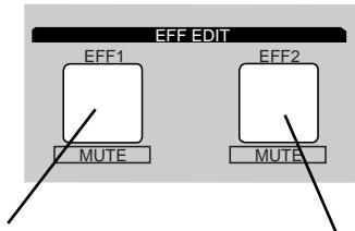
Press this to set the effect type for EFF 1.
Press this to set the effect type for EFF 2.
- As described earlier in "Basic Recording and Play back," raise the CHANNEL fader of a channel to which a signal is being input and raise the MASTER fader, so that the sound is heard at an appropriate level.
- As described earlier in "Setting the effect send level," raise the EFF 1 SEND level or the EFF 2 SEND level for the channel(s) to which you wish to apply the effect.
1.If you wish to set EFF 1, press the EFF EDIT mode [EFF 1] key. To set EFF 2, press the [EFF 2] key.
With the initial settings, the following displays will appear.
When the [EFF 1] key is pressed:
With the initial settings, "L01: Norm HALL" will appear.
![FOSTEX VF160EX - When the [EFF 1] key is pressed: - 1](/content/2025/01/168450/images/12f1d63a82148e1127012dda3fbd98f01d9ba7dbe6d26e5fe840307dd8e3fac6.jpg)
When the [EFF 2] key is pressed:
With the initial settings, "L35: CHORUS" will appear.
![FOSTEX VF160EX - When the [EFF 2] key is pressed: - 1](/content/2025/01/168450/images/c44cbb451bda75f2f2578b10ce8498d1c16528671b5bb3981a10856bec3a06a8.jpg)
2. Use the [JOG] dial to select the effect type.
The effect types listed in the foregoing tables will appear in succession. When an effect type appears, it will be blinking. The blinking indicates that the effect type has not yet been selected.
3. Press the [ENTER/YES] key.
The effect type will be finalized, and the parameter setting screen will appear.
The default (initial) parameter values will be displayed.
![FOSTEX VF160EX - Press the [ENTER/YES] key. - 1](/content/2025/01/168450/images/44ceae54de10e603a0d843309521548203c08d5e10d66964509320f3756f8d86.jpg)
Details on the parameters are given in the following section, "Parameter settings."
4. To exit Effect Edit mode, press the [EXIT/NO] key twice in succession.
You will return to Normal display.
When you press the [ENTER/YES] key to finalize the effect type, the sound will be muted for an instant.
Effect parameter settings
Here's how to set the effect parameters.
- If the effect parameter that you wish to adjust is not displayed, press the [EFF 1] key (or the [EFF 2] key) twice.
One of the parameters of that effect type will appear.
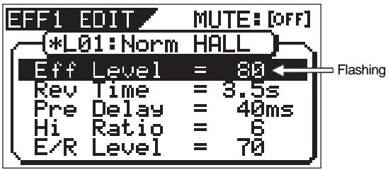
- Press the [EFF 1] key (or the [EFF 2] key) several times to display the desired parameter.
The parameters that appear will differ, depending on the effect type that is selected.
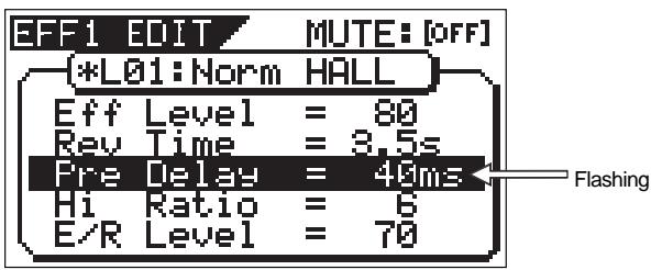
- Use the [JOG] dial to adjust the value.
For details on the meaning and range of each parameter, refer to "Effect parameter details" on the below.
- If you wish to adjust another parameter, repeat from .
- When you are finished making settings, press the [EXIT/NO] key twice to exit Effect Edit mode.
Muting an effect
You can mute the effect sound of effect 1 or effect 2.
- To mute the effect sound:
Hold down the [SHIFT] key and press the [EFF 1] key (or [EFF 2] key).
The effect sound of effect 1 (or effect 2) will be muted, and the dry sound will be heard.
When muting is on, the [EFF 1] key (or [EFF 2] key) LED is off.
Once again hold down the [SHIFT] key and press the [EFF 1] key (or [EFF 2] key).
The dry sound will change back to the effect sound. When mute is turned off, the [EFF 1] key (or [EFF 2] key) LED is off.
Effect parameter details
The parameters that can be adjusted will depend on the parameter type.
Reverb effect parameters (parameter type: REVERB)
For effect types 1--24 of the preceding "Effect type" table, the following four parameters can be adjusted.
1.Eff Level
Adjust the effect return level: 0~99
- Rev Time
Adjust the length of reverberation. Range: 0.1-9.9 seconds
3.Pre Delay
Adjust the time from the original sound until reverberation begins. Range: 0-100 ms
4.Hi Ratio
Adjust the decay ratio of the high frequencies. Range: 0--10
5.E/R Level
Adjust the volume of the early reflections. Range: 0--99
Delay+reverb effect parameters (parameter type: DELAY+REVERB)
For effect types 25--28 of the preceding "Effect type" table, the following four parameters can be adjusted.
1.Eff Level
Adjust the effect return level: 0~99
- Delay Time
Adjust the delay time: Range: 1--230 ms
3.Feedback
Adjust the number of delay repeats. Range: 0--99
- Delay Bal
Adjust the delay balance. Range: 0--99
5.Rev Time
Adjust the length of reverberation. Range: 0.1-9.9 seconds
Delay effect parameters (parameter type: DELAY)
For effect types 29 and 30 of the preceding "Effect type" table, the following four parameters can be adjusted.
1.Eff Level
Adjust the effect return level: 0~99
- Delay Time
Adjust the delay time. Range: 1-680 ms
3.Feedback
Adjust the number of delay repeats. Range: 0--99
4.Hi Ratio
Adjust the decay ratio of the high frequencies. Range: 0--10
5.Filter
Adjust the tone of the delay sound. Range: L9~L1, OFF, H1~H9
- L1~L9 = LPF (larger numbers will lower the cutoff frequency)
- H1~H9 = HPF (larger numbers will raise the cutoff frequency)
BPM delay effect parameters (parameter type: BPM DELAY)
For effect types 31 and 32 of the preceding "Effect type" table, the following four parameters can be adjusted.
1.Eff Level
Adjust the effect return level: 0~99
2.BPM
Adjust the BPM. Range: 30--250 bpm
If the delay time exceeds 680ms, "!" is shown.
- Note
Select the note value for the delay. Range: 24, 16, 8T, 16...8, 4T, 8., 4, 2T, 4., 2, 2., 1
- 24 = 16th note sextuplets, 16 = 16th notes, 8T = 8th note triplets, 16. = dotted sixteenth notes, 8 = 8th notes, 4T = quarter note triplets, 8. = dotted eighth notes,
4 = quarter notes, 2T = half-note triplets, 4. = dotted quarter notes, 2 = half notes
4.Feedback
Adjust the number of delay repeats. Range: 0--99 (100 steps in increments of 1)
5.Filter
Adjust the tone of the delay sound. Range: L9~L1, OFF, H1~H9
Tips: To reflect the tempo map setting to parameters
The BPM parameter value set by effect types 31 and 32 can be set in a range between 30 and 250. You can reflect the tempo value set by "Setting the tempo map" in the SETUP mode to this BPM parameter.
Therefore, you do not have to use the scene memory for changing the BPM value, and you can set the BPM value to follow the tempo map during playback.
To set the BPM value to follow the tempo map:
- Press the [EFF2] key, and use the [JOG] dial to select "L31:MonoBpmDL" or "L32:Pan BpmDL".
- Select "BPM" for the editing parameter and rotate the [JOG] dial clockwise.
If you furthermore rotate the dial clockwise after the value reaches "250" (which is the maximum value), the BPM value field shows "M", where "" shows the tempo value at the current position while "M" shows "map".
- After setting the BPM value to "***M", press the [EXIT/NO] key to quit the effect edit mode.
The operation above assumes that the appropriate tempo map is set in the SETUP mode.
If you carry out the operation above with the default tempo map (tempo = 120), the BPM value is set to "120".
If you do not want to reflect the tempo map value, set to a value with no "M".
Short delay effect parameters (parameter type: SHORT DELAY)
For effect type 33 of the preceding "Effect type" table, the following four parameters can be adjusted.
1.Eff Level
Adjust the effect return level: 0~99
2. Delay Time
Adjust the delay time. Range: 0.1-9.9 ms, 10-99 ms, 100-200 ms
3.Feedback
Adjust the number of delay repeats. Range: 0--99
4.Hi Ratio
Adjust the decay ratio of the high frequencies. Range: 0-10
5.Filter
Adjust the tone of the delay sound. Range: L9~L1, OFF, H1~H9
L1~L9 = LPF (larger numbers will lower the cutoff frequency)
H1~H9 = HPF (larger numbers will raise the cutoff frequency)
Doubling effect parameters (parameter type: DOUBLING)
For effect type 34 of the preceding "Effect type" table, the following three parameters can be adjusted.
1.Eff Level
Adjust the effect return level: 0~99
2.Lch Delay
Adjust the delay time of the L channel. Range: 0.1--9.9 ms, 10--99 ms, 100--200 ms
3.Rch Delay
Adjust the delay time of the R channel. Range: 0.1--9.9 ms, 10--99ms, 100--200 ms
4.Filter
Adjust the tone of the delay sound. Range: L9~L1, OFF, H1~H9
L1~L9 = LPF (larger numbers will lower the cutoff frequency)
H1~H9 = HPF (larger numbers will raise the cutoff frequency)
Chorus effect parameters (parameter type: CHORUS)
For effect type 35 of the preceding "Effect type" table, the following four parameters can be adjusted.
1.Eff Level
Adjust the effect return level: 0~99
- Depth
Adjust the chorus depth. Range: 0--99
- Double Time
Adjust the time difference of the doubling effect. Range: 0--99
- Double Lvl
Adjust the volume of the doubling effect. Range: 0--99
5.Filter
Adjust the tone of the delay sound. Range: L9~L1, OFF, H1~H9
L1~L9 = LPF (larger numbers will lower the cutoff frequency)
H1~H9 = HPF (larger numbers will raise the cutoff frequency)
Flanger effect parameters (parameter type: FLANGE)
For effect type 36 of the preceding "Effect type" table, the following four parameters can be adjusted.
1.Eff Level Adjust the effect return level: 0~99
2. Rate Adjust the speed of modulation. Range: 0.01 - 2.00Hz
3.Depth Adjust the depth of modulation. Range: 0--99
4.Mod Delay Adjust the modulation delay. Range:0--200
5. Feedback Adjust the number of modulation repeats. Range: 0--99
Mono pitch effect parameters (parameter type: MONO PITCH)
For effect type 37 of the preceding "Effect type" table, the following three parameters can be adjusted.
1.Eff Level Adjust the effect return level: 0~99
2.Pitch Adjust the amount of pitch shift. Range: -24--0--+24
+/-12 is one octave. +/-24 is two octaves.
- Adjust Make fine adjustments to the amount of pitch shift. Range: -50--0-+50
- +50 is a semitone sharp. -50 is a semitone flat.
4.Mode Select the processing method. Range: 1--3
Delay pitch effect parameters (parameter type: DELAY PITCH)
For effect type 38 of the preceding "Effect type" table, the following four parameters can be adjusted.
1.Eff Level Adjust the effect return level: 0~99
2.Pitch Adjust the amount of pitch shift. Range: -24--0--+24
+/-12 is one octave. +/-24 is two octaves.
- Adjust Make fine adjustments to the amount of pitch shift. Range: -50--+50
- +50 is a semitone sharp. -50 is a semitone flat.
- Delay Time Adjust the delay time until the pitch-shifted sound is heard. Range: 0--500 ms
5.Feedback Adjust the number of delay repeats. Range: 0--99
Scene Memory
The VF160EX provides 100 scene memories (Scene numbers 00 to 99). You can store a set of desired parameter settings to each memory. Items to be stored include all parameters set by the channel parameter edit and effect edit modes, as well as all channel fader levels. Furthermore, you can give a desired scene name with up to 16 alphanumeric or symbolic characters to each scene memory.
In addition to 100 scene memories, the VF160EX also provides 10 temporary memories (Temporary numbers 00 to 09). Note that all the setting stored in a temporary memory disappears when turning off the power.
Storing to a scene memory
You can store the current settings to a scene memory by the following procedure.
1. Press the [SCENE-STORE] key.
The display shows the screen for selecting the scene number.
![FOSTEX VF160EX - Press the [SCENE-STORE] key. - 1](/content/2025/01/168450/images/7f949cbaf785ab998566a8514b62840a98796b0d310a225ee36310e970845ed2.jpg)
2. Use the [JOG] dial to select the desired scene number to which you want to store the current settings, and press the [ENTER/YES] key.
The display shows the screen for editing a title of the selected scene number. The name of the program which you worked before entering the scene memory mode is duplicated to the name of the selected scene number, whose first character flashes, showing that it can be edited.
![FOSTEX VF160EX - Use the [JOG] dial to select the desired scene number to which you want to store the current settings, and press the [ENTER/YES] key. - 1](/content/2025/01/168450/images/cd545b2d756c692c10cda434e550dd782d5a4646db03debf84f6d2ac57c7c623.jpg)
3. Enter the desired scene name using the JOG dial for selecting a character and using the [REWIND]/[F FWD] keys for moving the editing (flashing) point.
You can specify a scene name with up to 16 alphanumeric or symbolic characters and can see up to 14 characters on the display. The following characters can be entered:
$$
\begin{array}{l} \hline A t o Z, a t o z, 0 t o 9, \ + - ^ {*} / # \& ! ( ) [ ] < >: .. , < - > \end{array}
$$
4. After completing the scene name entry, press the [ENTER/YES] key.
The display will change to the Normal display of the program whose scene name has been set.
Scene memories stored in the scene numbers (00 to 99) are preserved even if the power is turned off.
However, a temporary memory stored in the Temporary numbers disappear and all the parameters return to the default "Un-defined" settings when the power is turned off, though they do not disappear when changing the program. If you want to store the temporary memory to a scene number (00 to 99), recall the temporary number before turning off the power and store the memory to the desired Scene number (00 to 99).
Recalling a scene memory
You can recall the settings stored in scene memories.
1. Press the [SCENE-RECALL] key.
The display shows the screen for selecting the scene number.
![FOSTEX VF160EX - Press the [SCENE-RECALL] key. - 1](/content/2025/01/168450/images/d03684990eeed70221f303887f4c7b0daa51a1a95e745270d8ac30412b074428.jpg)
2. Use the [JOG] dial to select the desired scene number to be recalled, and press the [ENTER/YES] key.
After "Scene Recalled" appears on the display, the selected scene is recalled and the display changes to the Normal display.
- The contents recalled differ depending on the settings in the "Fader recall" menu in the SETUP mode. See "Settings for fader recall" menu in the SETUP mode for the detailed information.
- Regardless of the current physical positions of channel and master faders, audio is output at the fader position location when they were stored. We suggest you turn the audio volume down when recalling a scene memory to prevent accidentally accessing high-volume sound.
- When switching the display to the fader adjust, level adjust or fader view screen, the [FADER ADJUST] key may flashes (when the fader recall setting is not set to "Off"). This indicates that the fader position in the current scene does not match the physical fader position. In such a case, you can turn off the key by adjusting the fader to the position in the current scene or by adjusting the level to the current physical position. See the following description for details about the fader adjustment and level adjustment.
Level adjust
When recalling a scene memory, if the recalled fader level does not match the current physical fader position (the red indicator of the [FADER ADJUST] key flashes), you can adjust the level to match the current fader position.
1. Press the [FADER ADJUST] key while holding down the [SHIFT] key.
The unit enters the Level adjust mode.
The fader icons appear on the display, as well as flashing "Sure?". The recalled fader positions are shown as fader knob positions while the current fader positions are indicated by > and < . In the following example, all recalled fader positions are at the lowest positions.
![FOSTEX VF160EX - Press the [FADER ADJUST] key while holding down the [SHIFT] key. - 1](/content/2025/01/168450/images/d5456498d529724c5ae65af6cf2a7261e0e9889fd52794031fb2b9c4308add53.jpg)
2. Press the [ENTER/YES] key.
The display shows "Completed!", immediately followed by the Normal display after each actual (internal) fader position is set to match the corresponding physical fader position. The flashing indicators of the FADER ADJUST turn off. With the example above, all actual faders are set to minimum.
Fader adjust
When recalling a scene memory, if the recalled fader level does not match the current physical fader position (the red indicator of the [FADER ADJUST] key flashes), you can move the physical faders to match the current fader positions of the scene.
The following description is assumed that "Fader recall setting" of the SETUP mode is set to "CH&MST".
1. Press the [FADER ADJUST] key alone.
The unit enters the Fader adjust mode.
The fader icons appear on the display, as well as flashing "Select CH!".
The recalled fader positions are shown as fader knob positions while the current fader positions are indicated by “>” and “<”.
![FOSTEX VF160EX - Press the [FADER ADJUST] key alone. - 1](/content/2025/01/168450/images/4dc17fd49ff5b837d2a554916cf586adb2e0bf1eeddb1eceb9211f18668df76b.jpg)
If you press the [FADER ADJUST] key when the fader recall setting is set to "Off", the display shows "Fader Recall Off" and then returns to the Normal display.
2. Select the channel to be adjusted by pressing the corresponding [CH STATUS/CH SEL] key, and move the corresponding physical fader.
In the screen example below, the physical fader position of channel 1 matches the recalled fader position.
![FOSTEX VF160EX - Select the channel to be adjusted by pressing the corresponding [CH STATUS/CH SEL] key, and move the corresponding physical fader. - 1](/content/2025/01/168450/images/fda0c3d9578ca5942851efde91741b616d5f7a68352a7a74b111f948344ad031.jpg)
If two adjacent channels are fader-paired, pressing the [CH STATUS/CH SEL] key for the odd channel selects both channels and you can simultaneously control both channels. The fader icon for the even channel as shown in a dotted line, indicating that you do not have to adjust it.
The fader icons below are examples of indicating different status.
![FOSTEX VF160EX - Select the channel to be adjusted by pressing the corresponding [CH STATUS/CH SEL] key, and move the corresponding physical fader. - 2](/content/2025/01/168450/images/432cdc98dd79c3b52682884c6e1ad65a152255d4a4136c2d7e9113ad4867ef8f.jpg)
3. Repeat the previous step for each channel.
4. After adjusting all the fader positions, press the [EXIT/NO] key.
The indicator of the [FADER ADJUST] key turns off.
The previous description for "Fader adjust" is assumed that "Fader recall setting" of the SETUP mode is set to "CH&MST". However, the default of "Fader recall setting" is "Off".
In this setting, the indicator of the [FADER ADJUST] key will not flash when recalling a scene memory, because the fader positions are not recalled and the current fader positions remain effective.
Therefore, if you want to make the recalled fader positions of a scene memory effective, set the "Fader recall setting" properly according to your requirement. See "SETUP mode" on page 145 for details about the fader recall setting.
If the fader recall setting of the SETUP mode is set to "CH", the display shows the screen as below when the unit enters the fader adjust mode, indicating all the channel fader positions are recalled, while the master fader position is not recalled.
Moving the master fader in this mode directly affects the actual fader level.
![FOSTEX VF160EX - After adjusting all the fader positions, press the [EXIT/NO] key. - 1](/content/2025/01/168450/images/664b7b8fe06a72096460b3cc1a678dbe4682dea0f188695bda00b8b345ef7c2e.jpg)
Direct recall of a scene memory
Besides recalling a scene memory by selecting the desired scene from the list as described above, you can recall a scene directly.
You can directly recall only the scene memories following to the current scene.
For example, if the current scene number is 05, while scene memories are stored in scene numbers 01 through 10, you can directly recall scene numbers 06 through 10.
Also note that scene number 00 cannot be recalled.
1. Press the [SCENE-RECALL] key while holding down the [SHIFT] key.
Every time you press the [SCENE RECALL] key while holding down the [SHIFT] key, the next scene is recalled.
You cannot use the direct recall function When there is no scene that stores data other than scene number 00, or when the highest scene number is recalled. If you carry out the above operation, the display will show "No-additional Scene" and the operation is ignored.
When a scene is directly recalled, the "Fader recall setting" of the SETUP mode is also effective, as described in "Recalling a scene memory" above.
Clearing a scene memory
You can clear an unnecessary scene memory by using the following procedure.
You cannot clear the memories in scene number 00 or current scene (whose scene number flashes in the screen)
If you select scene number 00 and try to clear the memory, "Warning Can't Clear Current Scene" appears on the display and the operation is ignored.
1. Press the [SCENE RECALL] and [SCENE STORE] keys simultaneously.
The display shows the screen for selecting a scene to be cleared. "**" shows a user-defined scene name.
In the next step, you can select any scene number except "S00 Init Mix".
![FOSTEX VF160EX - Press the [SCENE RECALL] and [SCENE STORE] keys simultaneously. - 1](/content/2025/01/168450/images/33c6064c7a6a77c5d749b6a76625cc5f7ff70e0098c0bfdd569abaa8694011e5.jpg)
2. Select the desired scene to be cleared using the [JOG] dial, and press the [ENTER/YES] key.
The confirmation message for clearing the selected scene appears, in which "Sure?" flashes.
To cancel the operation, press the [EXIT/NO] key.
3. Press the [ENTER/YES] key.
The selected scene memory is cleared and the scene name changes to "[Un-defined]", showing that no memory is stored.
Scene Event Map
By creating a scene event map, you can recall desired scene memories (mixer settings) at desired positions during playback. For example, you can recall scene memory 02 at 00H 01M 34S 00F and scene memory 04 at 00H 02M 20S 20F, etc. In the following description, we assume that the time base is set to ABS.
However, you may set the time base to Bar/Beat/Clk which allows you to specify the event position by Bar/Beat/Clk
numbers.
You must store data to scene memories used in a scene event map in advance. See "Scene memory" above about how to store the current settings to a scene memory.
Creating an event memory
An event memory can be created via two methods.
- on the fly
- by specifying a desired time
You can create up to 99 event memories (01 to 99).
Tips:
In addition to the methods shown above, during the digital scrub operation, you can register the time after scrubbing by pressing the [HOLD/>] key, followed by [LOCATE] key while holding down the [SHIFT] key.
See "Chapter 4 Recorder Functions" for details about digital scrubbing.
Creating an event memory on the fly
1. At the desired position while the VF160EX is stopped or during playback, press the [HOLD/>] key.
The time when pressing the [HOLD/>] key is held.
LOCATE=00H01m59s24f99sf
HOLD
2. Press the [STORE] key.
LOCATE=08H91M58s24F83sf Hit Any Memory Keys!
3. Press the [LOCATE/EVT MEM] key while holding down the [SHIFT] key.
"Entry EVT**"(where ** shows the event memory number) appears for a short time, while the time held in step 1 is entered in the event memory.
4. To create other event memories, repeat step 1 through 3 above.
An event memory created by the above procedure only contains event time data. To set the desired scene number to be recalled to each event memory, see "Creating the scene event map" described later.
Event memory numbers are assigned in ascending order of ABS time, regardless of order in which event memories are created. For example, if you first create an event memory 1 (EVT01) with data "05m 00s" and then create an event memory with data "03m 30s", the event memory 1 data is replaced with "03m 30s" automatically, while the previous data ("05m 00s") is assigned to event memory 2.
The event memories created in real-time by the procedure described above can be viewed by the operation below.
1. While the VF160EX is stopped, press the [SCENE STORE/ MAP] key while holding down the [SHIFT] key.
The screen shows the event memory list as below, in which you can view and check the event memories created in real-time.
![FOSTEX VF160EX - While the VF160EX is stopped, press the [SCENE STORE/ MAP] key while holding down the [SHIFT] key. - 1](/content/2025/01/168450/images/4ec494e1283afcf927ac4ea69beeada7a14fe1880aefaeb728839138475169ec.jpg)
Tips:
The event memory number that is nearest to the current position flashes in the screen above.
By selecting the desired event number using the [JOG] dial and pressing the [LOCATE] key, you can locate the event memory position.
Creating an event memory by specifying the desired time
- The following procedure is assumed that no event memory has been created.
Event memory "00" cannot be edited.
1. While the VF160EX is stopped, press the [SCENE STORE/ MAP] key while holding down the [SHIFT] key.
The display shows the screen for selecting event memory numbers. When no event memory is created, the screen shows as below.
![FOSTEX VF160EX - While the VF160EX is stopped, press the [SCENE STORE/ MAP] key while holding down the [SHIFT] key. - 1](/content/2025/01/168450/images/fe6cf27e7ad180f5b4a76fd6e85eb5186265578873f5c983032acecf78b23169.jpg)
2. Select "01 New Event" using the [JOG] dial, and press the [ENTER/YES] key.
Rotate the [JOG] dial to highlight "01 New Event".
By pressing the [ENTER/YES] key, the event edit screen appears, where "Non" flashes in the Scene number field.
![FOSTEX VF160EX - Select "01 New Event" using the [JOG] dial, and press the [ENTER/YES] key. - 1](/content/2025/01/168450/images/383422a4f9ac8b0a07039c6fabf9b373b067bf8fcdde42b5a81f70951fe74c8d.jpg)
While "Non" is flashing, you can selects the scene number from those currently stored by rotating the [JOG] dial.
The corresponding scene names are also shown below. If no scene memory except the initial setting "S00 Init Mix" is stored, selecting any scene number (01 to 99) except 00 shows "Un-defined" on the screen.
In the description here, we skip selecting a scene number ("Non" continues to flash) and go to the next step for time editing. You may, of course, select a scene number after editing the event time.
3. Use the [F FWD] key to select the flashing (editing) field in the time display.
Each time you press the [F FWD] key, the flashing (editing) field moves from h -> m -> s -> f -> sf, while each press of the [REW] key moves the flashing field in reverse order.
4. Rotate the [JOG] dial to enter the desired value for the editing field.
Repeat step 3 and 4 to enter the desired values to all fields.
5. Press the [ENTER/YES] key after editing the time.
The event memory with the edited time is created, and the display returns to the Normal Display.
6. To create other event memories, repeat step 1 through 5.
Creating the scene event map
After preparing the event memory list, you can create the scene event map.
Note that all necessary scene memories must be stored in advance when carrying out the following.
1. While the VF160EX is stopped, press the [SCENE STORE/ MAP] key while holding down the [SHIFT] key.
The screen shows the event memory list.
![FOSTEX VF160EX - While the VF160EX is stopped, press the [SCENE STORE/ MAP] key while holding down the [SHIFT] key. - 1](/content/2025/01/168450/images/50afa337d46e8697f3200ae734f24ebec35b323555a561ec4926634e3f0c74e4.jpg)
2. Select the desired event memory using the [JOG] dial, and press the [ENTER/YES] key.
The display shows the screen for selecting the scene number for the selected event memory ("Non" flashes).
3. Select the desired scene number by using the [JOG] dial, and press the [ENTER/YES] key.
The selected scene number is assigned to the event memory. In the example shown below, a scene number is assigned to each event memory.
![FOSTEX VF160EX - Select the desired scene number by using the [JOG] dial, and press the [ENTER/YES] key. - 1](/content/2025/01/168450/images/e9a441bae0b5cda052d7153612858b68ce7de0f2a677e7b501dd9981c7b86cf8.jpg)
Deleting an event memory
You can delete unnecessary event memories.
You cannot delete event memory 00.
1. While the VF160EX is stopped, press the [SCENE STORE/ MAP] key while holding down the [SHIFT] key.
The screen shows the event memory list.
2. Select the desired event memory using the [JOG] dial, and press the [ENTER/YES] key.
The display shows the screen for selecting the scene number for the selected event memory.
3. While the scene number is flashing, rotate the [JOG] dial counterclockwise.
"EVT DEL" (Event Delete) flashes in the scene number field, showing that the event memory selected above is ready to be deleted.
![FOSTEX VF160EX - While the scene number is flashing, rotate the [JOG] dial counterclockwise. - 1](/content/2025/01/168450/images/fad8d7dd47644a43be7ea76ac1e43cab43071b767ce2085f744abaac520f33f8.jpg)
4. While "EVT DEL" is flashing, press the [ENTER/YES] key.
The confirmation message for deleting the selected event memory, in which "Sure?" flashes.
5. Press the [ENTER/YES] key
To cancel the operation, press the [EXIT/NO] key.
The selected event memory is deleted and the screen shows the event memory list.
6. Press the [EXIT/NO] key (or the [STOP] key).
The display returns to the Normal display.
Scene sequence mode on/off selection
You can turn on or off the scene sequence mode for selecting whether or not executing the scene sequence program using the scene event map.
1. While the VF160EX is stopped, press the [A RTN A PLAY/SCENE SEQ] key while holding down the [SHIFT] key.
After "SCENE SEQ: ON" is briefly shown on the screen, the Normal display appears.
Each time you press the [A RTN A PLAY/SCENE SEQ] key while holding down the [SHIFT] key, ON and OFF alternates. When the scene sequence mode is set to ON, the scene number indicator on the Normal display is highlighted (When OFF, it is not highlighted).
![FOSTEX VF160EX - While the VF160EX is stopped, press the [A RTN A PLAY/SCENE SEQ] key while holding down the [SHIFT] key. - 1](/content/2025/01/168450/images/68b5a614625fde3e5a7e9c5917176467ed28deb6e0223861b797a8773d9dd256.jpg)
Executing the scene sequence
When the scene sequence mode is set to ON, the scenes will be recalled according to the scene event map during playback.
- When executing the scene sequence, the fader positions are recalled according to the fader recall mode in the SETUP mode (the default is "Off"). For example, if you set the fader recall mode to "CH & MST", both the channel and master faders are automatically recalled every time the current scene changes. On the contrary, if you set the fader recall mode to "Off" (the default mode), fader positions are not recalled so you can manually control fader positions as you like.
We suggest you to make sure to set the fader recall mode suitably for your work before executing the scene sequence. See page 145 for details about the fader recall mode setting.
- When you do not use the scene sequence function, set the scene sequence mode to OFF.
- Effect presets of the internal effect processor are classified into three types; ambience/delay type (No.1 through 28), modulation/pitch type (No.29 through 36) and pitch type (No.37 and 38). Note that the scene sequence function does not recall an effect preset whose type is different from the current one. This is to avoid momentary audio muting, and is not a malfunction. The other mix parameters of the scene can be recalled even if it includes an effect preset whose type is different from the current one.
The following show the screen appearances during playback with the scene event map in which scene number 02 (with title "XXX") is recalled at 01m30s and scene number 05 (with title "YYY") is recalled at 05m00s .
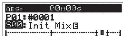
The unit starts playback with scene number 00 (Init Mix).
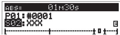
The unit recalls scene number 2 (XXX) at 01m 30s and continues playback.
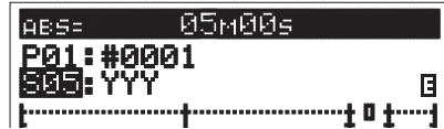
The unit recalls scene number 5 (YYY) at 05m 00s and continues playback.
The unit continues playback with the scene number recalled by the last event memory.
Therefore, if you want to recall scene number 00 again after recalling scene number 05, you have to create the last event memory that recalls scene number 00 at the desired time.
Chapter 4 Recorder Functions
This chapter describes the cueing/digital scrubbing function, vari pitch control, auto functions, program management and track editing (such as copy/paste, move/paste, erase, track exchange, etc.).
Cueing/Digital Scrubbing
This section describes the cueing feature for cueing sound during the F FWD or REWIND process.
Cueing with the [F FWD]/[REWIND] key
The user can cue at 3x speed by pressing the [F FWD]/[REWIND] key while the recorder is playing.
- Start playback by pressing the [PLAY] key.
- Press the [F FWD] or [REWIND] key during playback. Either “FWD>” or “<RWD” will appear on the LCD. Then 3x speed cuing starts in the direction chosen.
![FOSTEX VF160EX - Cueing with the [F FWD]/[REWIND] key - 1](/content/2025/01/168450/images/f80173d8673c66ca152c2d070850a211c824ca920c4bbbe2fbba398442c2055c.jpg)
- Press the [PLAY] key to return to the original play speed (1x speed).
Shuttle Cueing
Shuttle cueing at a cue speed between 1-64x is possible by turning the [JOG] dial while the [SHIFT] key is depressed when the recorder is playing. The speed varies according to the degree the dial is turned.
- Press the [PLAY] key to start playback.
-
Turn the [JOG/SHUTTLE] dial to the left/right while the [SHIFT] key is depressed.
-
Turn the [JOG] dial to the right to shuttle cue in the FORWARD direction.
Turn the [JOG] dial to the left to shuttle cue in the REWIND direction.
- The cueing speed varies from 1x, 2x, 4x, 8x, 16x, 32x and 64x according to the degree (angle) in which the [JOG] dial is turned. The current cueing speed appears on the LCD.
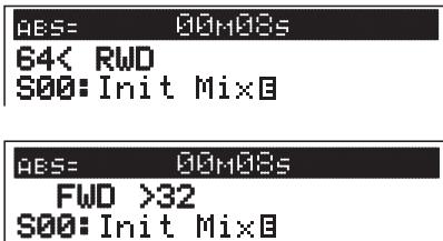
-
Shuttle cueing continues as long as the [SHIFT] key is depressed, even when the [JOG] dial isn't used.
-
Lift finger from [SHIFT] key to return to the original play speed (1x).
Once the data is rewound to the beginning of a program (ABS 0), playback starts from the beginning of the program, regardless of pressing the [SHIFT] key. When reaching the end of a program (ABS:23H 59M 59S), the program stops and the [PLAY] key flashes.
Digital scrubbing with the [SCRUB] key
To enter the Digital Scrub Mode, press the [SCRUB] key while the recorder is in the STOP state to cue at 0-1x speed without any change in musical key.
Digital scrub is possible for each track. The level envelope (volume wave form) of that track appears. This feature is effective when it is necessary to conduct a pinpoint search of the beginning of a song or a point (location) between songs.
- Press the [SCRUB] key while the recorder is in the STOP state.
The scrub mode is activated and the following display appears.
![FOSTEX VF160EX - Digital scrubbing with the [SCRUB] key - 1](/content/2025/01/168450/images/dc1dd4a1b72d5a4ed012abca0077c82d6ee53d94b485eefca88621e42893080e.jpg)
- Press the [CH STATUS/CH SEL] key of the track to scrub. The level envelope of the selected track appears. The first time you enter the scrub mode after turning on the power, the magnification is set to x 1.
![FOSTEX VF160EX - Digital scrubbing with the [SCRUB] key - 2](/content/2025/01/168450/images/e5d0cb6079a5edd1c0bfbac454fd168960a075ebe733834f3f7e2959d23c1392.jpg)
Tips: How to change the zoom magnification
You can select the zoom magnification by using the [F FWD] and [REWIND] keys. Each press of the [F FWD] key increases the magnification from x 01 -> x 02 -> x 04 -> x 08 -> x 16. Each press of the [REWIND] key decreases the magnification. The magnification setting is global for all tracks, and is shown at the bottom of the display. Also, when the magnification is not set to x 01, you can temporarily change it to x 01 while holding down the [SHIFT] key. Note that the magnification is resets to x 01 when turning off the power.
3. Turn the [JOG] dial left and right to hear the playback sound of only the track selected.
The center line indicates the current location. Scrub takes place in the FORWARD or REWIND direction from this point. Either "" appears when turning the [JOG] dial, which moves the cursor forward or reverse. The time value (or BAR/BEAT) also appears in realtime while scrubbing.
4. Press the [STOP] key to return to the normal display.
The time display when ending the scrub process appears.
Variable Pitch Control
This section describes the Variable Pitch Control feature to play or record programs at variable recorder speeds. The VF160EX can change the speed in 0.1% units within a + / - 6.0% range. Note that the key changes when changing the variable pitch speed.
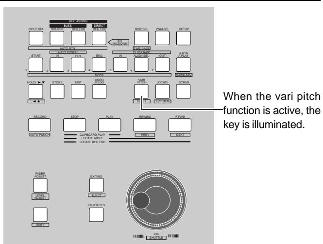
Variable Pitch Control ON/OFF
* Press the [VARI PITCH] key.
The key lights up GREEN. This means the feature is ON.
* Press the [VARI PITCH] key once again.
The key lights OFF. This means that the feature is OFF.
The variable pitch control can be turned ON/OFF when the recorder is in the STOP/PLAY modes. Variable pitch control is not available when the recorder is recording, even though the key is pressed.
Setting the Speed
Note that the speed can be set only in the recorder STOP or PLAY mode. It cannot be changed when the recorder is recording. By playing back a program with the variable pitch control ON it is possible to adjust the speech while monitoring the changes.
1. Put the recorder in the STOP or PLAY mode. Press the [VARI PITCH/P.EEDIT] key while the [SHIFT] key is depressed.
The current setting appears on the LCD and % flashes. This means that the recorder is ready to edit with the variable pitch control feature.
![FOSTEX VF160EX - Put the recorder in the STOP or PLAY mode. Press the [VARI PITCH/P.EEDIT] key while the [SHIFT] key is depressed. - 1](/content/2025/01/168450/images/fa5dfda73a3fca765e3d5485e446376200c3c678005dda2667e7f19b38f7bbee.jpg)
Variable pitch control ON/OFF alternates between ON and OFF each time the [VARI PITCH] key is pressed in this state.
"CH" or "OFF" lights up.
![FOSTEX VF160EX - Put the recorder in the STOP or PLAY mode. Press the [VARI PITCH/P.EEDIT] key while the [SHIFT] key is depressed. - 2](/content/2025/01/168450/images/344cf0da391bd7bbf93a4b5c2b88513c92ce71e41f66f29bb6f90966f31d40a6.jpg)
2. Turn the [JOG] dial to set the setting.
3. Press the [EXIT/NO] key to return to the normal display.
Auto Function
The VF160EX is equipped with 3 Auto Functions. One is the "Auto Play", which automatically starts playing a track after locating it. Another is the "Auto Return", which locates a predetermined time during playback. The third, "Auto Repeat", combines the former two features to repeat playing a certain segment.
Use the [A RTN/A PLAY] key to start the Auto Function. Every time the key is pressed the function switches through "Auto Play" -> "Auto Return" -> "Auto Repeat" -> "OFF". The Normal Display will show an icon of each functional status.
Auto Play
- Press the [A RTN/A PLAY] key during the Normal Display, to display the Auto Play icon (see figure below) on the LCD.
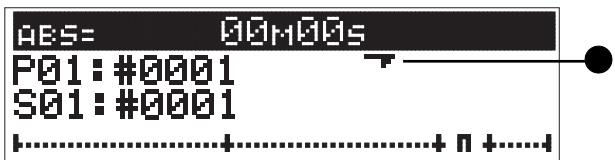
- Follow the above location instructions to locate a chosen point.
Playback automatically starts from the time located.
Auto Return
The Auto Return function automatically locates a START point when the track is played to the END point. To execute the Auto Return function, you must set the START point and END point time.
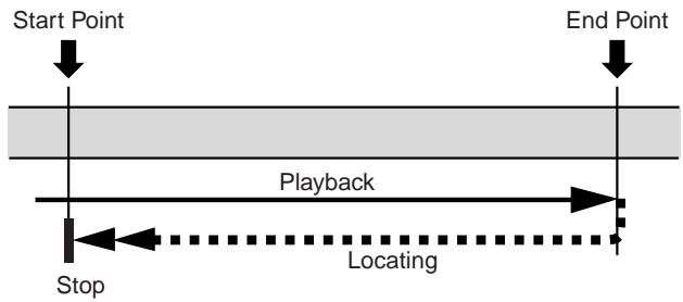
Set (Store) START/END Point
- Press the [STORE] key at the time to set.
This key can be pressed during then play or stop mode.
- Press the [AUTO RTN-START] key or [AUTO RTN-END] key.
The time is set at the respective points, and then the LCD returns to the Normal Display.
The VF160EX stops when a time is stored during playback.
Always set the START point time before the END point time. The Auto Return functions will not operate properly unless the start and end times are set correctly.
- Press the [A RTN/A PLAY] key in the Normal Display to display the Auto Return icon on the LCD. (see figure below)
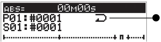
- Play the VF160EX from the point immediately before the END point time.
Auto Return then takes effect.
Auto Repeat
Auto Repeat is a combination of Auto Play and Auto Return. When play reaches the END point, the function automatically locates the START point.
By automatically starting to play after locating the START point, it becomes possible to repeatedly playback a certain segment.
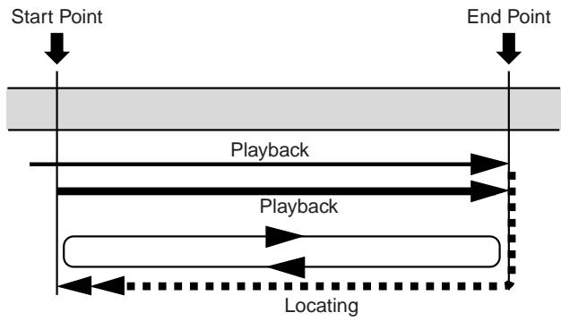
- Set the START point time and END point time, the same as the "Auto Return" function.
- Press the [A RTN/A PLAY] key in the Normal Display to display the Auto Repeat icon on the LCD. (as shown in figure below)
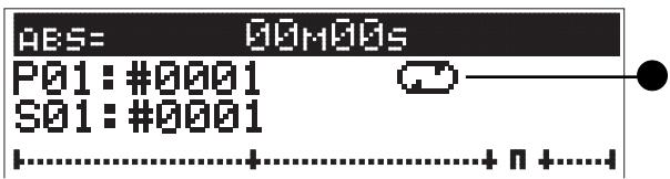
- Start playing the VF160EX from the point immediately before the END point time set.
Auto Repeat will take effect.
Program
With the VF160EX, the music is managed according to programs numbered 01-99 (99 programs). These programs are independent of each other and can be recorded or played separately. This section describes the instructions of how to operate the program.
Creating a New Program
One program (P01) is automatically created on the VF160EX when formatting the hard disk. Follow the instructions below to create a New Program.
Note that the VF160EX must be in the STOP mode.
The contents as the program currently started is copied as the default setting of a newly created program.
To keep the same default settings as previously created programs, first start up the previous program and then create a new program.
1. Press the [PGM SEL] key in the STOP state.
The current program number and "Select PGM!" appears, then "Sure?" flashes on the LCD.
![FOSTEX VF160EX - Press the [PGM SEL] key in the STOP state. - 1](/content/2025/01/168450/images/bb1d23cf414f360ee7098179e1a647068af41a8a64b69b3be484017191c0d853.jpg)
2. Turn the [JOG] dial clockwise to find "New PGM?", then press the [ENTER/YES] key.
A new program is created, then automatically proceeds to the "Title Edit" menu of the SETUP mode. This allows the user to input (edit) the title name of the newly created program.
Press the [EXIT/NO] key twice to create a program with a working title, without editing the title.
When the [EXIT/NO] key is pressed, the system returns to the Normal Display. To edit the working title, proceed as follows.
![FOSTEX VF160EX - Turn the [JOG] dial clockwise to find "New PGM?", then press the [ENTER/YES] key. - 1](/content/2025/01/168450/images/c142685227162fc8f701064860dec302ef6261c2ca128523e0173f10c4b9ab08.jpg)
3. Press the [ENTER/YES] key again.
The "Tentative Title" (#0002, etc.) that was automatically assigned when creating a new program appears on the LCD. The left end of the title is highlighted and flashes.
This means that the tentative (working) title of the newly created program can be edited. Edit the title in the following manner.
Note that the "Title Edit" function described later can also edit or reedit the title of a new program already assigned a title or one that was edited.
- Turn the [JOG] dial at the cursor (flashing point). The following alphanumeric can be selected.
- Shift through the cursor (flashing point) by pressing the [HOLD/>] key, [REWIND] key or [F FWD] key.
- Rotate the [JOG] dial while holding down the [SHIFT] key and the recorder will jump to the letters/symbols listed below (small square position).
$$
# \text {本} ^ {\prime} \& ^ {\prime} (\cdot) * +, -, \sqrt [ 4 ]{1 2 3 4}
$$
$$
5 6 7 8 9:; < = >? \sqrt [ n ]{A B C D E F}
$$
$$
G H I J K L M N O P Q R S T U V W X
$$
$$
Y Z [ \yen ] ^ {\wedge} _ \text {a b c d e f g h i j}
$$
$$
k l m n o p \text {r s t u v w x y z (}
$$
$$
} \rightarrow \left. - \boxed {!} ^ {\prime \prime} \right.
$$
4. Press the [ENTER/YES] key after assigning a title.
The program is set with the title assigned.
5. Press the [EXIT/NO] key (or [STOP] key).
The user escapes from the SETUP mode and the Normal Display of the newly created program appears on the LCD.
- Note that when creating a new program, the next sequential number of the program currently set on the disk is set. If there is only one program, then program number 2 (P02) is created. If there are five programs, then program number P06 is assigned.
- The program name started when creating a new program is directly copied for the scene name (S01: #0002, etc.) appearing below the program number.
- Available disk space is slightly reduced by creating a new program. The user cannot create a new program when there is not enough disk space available to save that program.
Selecting a Program
If there are several programs set on the disk, there may be a need to select a target program. The following instructions are based on the VF160EX in the STOP status in the Normal Display.
1. Press the [PGM SEL] key in the STOP state.
The current program number and "Select PGM!" appears, then the "Sure?" message starts flashing on the LCD.
2. Turn the [JOG] dial display to select the target program number (flashing).
"New PGM?" appears when turning the [JOG] dial clockwise. Use this to create a new program, according to the instructions as described above.
3. Select the target program number (flashing), then press the [ENTER/YES] key.
The Normal Display of the selected program appears.
Erasing a Program
The user can erase unnecessary programs. Note that there must be sufficient storage space (disk space available to store new/more data) on the hard disk to record or edit existing programs. By erasing an unnecessary program from the disk, the user can make more disk space and thus, ensure smooth operations of other functions.
- The program started prior to executing the ERASE function is the program that is going to be erased. Therefore, the user must start the program to erase according to the "Selecting a Program" instructions, described above.
- If a program is erased when there is only one program on the disk, then only the data saved for that program is erased. Note that an empty program 1 (P01) will remain on the disk even in such case.
- Let's take the following case as an example. As shown in the figure below, there are five programs from P01 to P05. Note that the program numbers always remain in sequential order. Therefore, when program number P03 is erased, there will only be a total of 4 programs. This means though the data on P03 is erased, and the numbers are sequentially corrected (no number is skipped). Note that only the contents of P03 are erased and the numbers are merely reassigned in sequential order according to the number of programs available. Simply put, P04 becomes P03 and P05 becomes P04, when P03 is erased, as in this case.
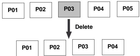
- Remember that it is not possible to UNDO/REDO (unerase or re-erase) the ERASE feature once a program is erased.
1. Press the [SETUP] key in the STOP state.
The system goes to the SETUP mode and proceeds to the SETUP menu selection display.
The current program number appears and "Sure?" flashes (***: Title). To cancel the ERASE procedure, press the [EXIT/NO] key while "Sure?" is flashing.
![FOSTEX VF160EX - Turn the [JOG] dial to select the "Delete" menu, then press the [ENTER/YES] key. - 1](/content/2025/01/168450/images/a86f4582c3a6f027537c4f363a83e0dd7babd43400b376bcff090aa3dfd59d6c.jpg)
3. Press the [ENTER/YES] key.
The Normal Display of the next program following the program erased appears.
Editing a Program Title
Note that the program title can be assigned when "Creating a New Program" as described in the previous section. However, the user must follow the instructions below to edit a title (or Tentative Title) that has already been assigned.
Note that only the title of the program that is started up can be edited.
The user cannot choose a program from the SETUP mode. Therefore, the user must first start the program to edit, before going to the SETUP mode.
1. Press the [SETUP] key in the STOP state.
The system goes to the SETUP mode and proceeds to the display to select a SETUP menu.
The title (name) of the current program started appears. The left end of the title is highlighted and flashes. (the flashing cursor indicates that it is editable)
![FOSTEX VF160EX - Turn the [JOG] dial to select the "Title Edit" menu, then press the [ENTER/YES] key. - 1](/content/2025/01/168450/images/44b71ce6ad3c911ee59c95517095afa7d220ca237f8a303afb69c0a6474c6448.jpg)
The title can contain up to 16 characters from the following alphanumeric and symbols.
$%&( )+, -./01234
56789: < = >? ABCDEF
GHIJKLMNOPQRSTUWX
YZ[¥]^_`abcdefghij
klmnoparstuvuxz(1
)→←!"
The title input is set and the LCD returns to the Normal Display.
Editing the Track
The VF160EX features a 3.5 inch E-IDE hard disk as a storage media. This allows speedy voice editing in a nonlinear and nondestructive manner in track units. There are four track editing options as described below.
Copy & Paste
A specific range of data on a voluntary track can be copied and then pasted to the same track or another track. Note that the Copy & Paste feature is only possible with the current program started.
Move & Paste
A specific range of data of a voluntary track can be moved and pasted to the same track or another track. Note that the Move & Paste feature is only possible with the current program started.
Erase
A specific range of data on a voluntary track or on all real tracks are erased. Note that the Erase feature is only possible with the current program started.
Track Exchange
Tracks are interchangeable with each other.
Mono tracks or several (2 track or 8 track unit) tracks are exchangeable, to freely exchange between the 24 real tracks and additional tracks. Note that the Track Exchange feature is only possible with the current program started.
- DO NOT change the program during the editing process until the entire editing process is completed, since the editing process only effects the program currently selected.
- Note that the editing process other than Track Exchange is only an option for real tracks (Trk 1-16). To edit data on additional tracks (Trk 17-24), exchange it to a real track to execute the editing process.
Copy & Paste and Move & Paste
Copy & Paste
Copy & Paste refers to the procedure to temporarily copy to a clipboard (Copy/Clip) a specific range of data on a voluntary track. That copied data can then be pasted to a specific paste point on a voluntary track. Since, the data copied remains in the clipboard even after pasting the data, that same copied data can be pasted numerous times.
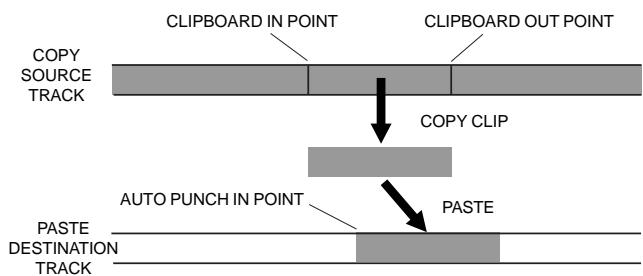
Move & Paste
Move & Paste resembles the Copy & Paste feature and refers to the procedure to temporarily move to a clipboard (Move/Clip) a specific range of data on a voluntary track. The difference between the Move & Paste and Copy & Paste feature is that with Move & Paste the original data moved can only be pasted ONCE. At the point the move data is pasted the data in the clipboard and original data is no longer available to paste again.
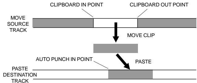
Copy & Paste and Move & Paste
This section describes the Copy & Paste (or Move & Paste) details.
- The data copied (or moved) on the clipboard is replaced with new data every time data is copied (or moved).
- Note that the data copied in the clipboard is replaced when pasting over the original data copied.
Executing Copy (or Move) and CLIP
1. Set the point to start COPY (or MOVE) and the point to start the PASTE feature.
Set the COPY (or MOVE) starting point to the [CLIPBOARD IN] key, the ending point to the [CLIPBOARD OUT] key, and the PASTE starting point to the [AUTO PUNCH IN] key.
For more details on how to set (store) to the memory key refer to page 34.
2. Press the [EDIT] key to proceed to the "Copy Clip?" (or "Move Clip?") message.
To execute the Copy & Paste feature select "Copy Clip?".
![FOSTEX VF160EX - Press the [EDIT] key to proceed to the "Copy Clip?" (or "Move Clip?") message. - 1](/content/2025/01/168450/images/5d463661298b33138a7c5edb7e73abe5a2cd593caa32e94c4c1b4d28b5387904.jpg)
To execute the Move & Paste feature select "Move Clip?".
![FOSTEX VF160EX - Press the [EDIT] key to proceed to the "Copy Clip?" (or "Move Clip?") message. - 2](/content/2025/01/168450/images/cb195a99037413de14852613e2f57c4e29cf261ddaa43fb37f2ff9df4e6dbd63.jpg)
3. Use the [CH STATUS/CH SEL] key to select the track to COPY (or MOVE).
Both mono tracks and multiple tracks (including ALL tracks) can be selected. During the Copy & Paste (or Move & Paste) process it is only possible to change the paste destination track of mono tracks or when copying (or moving) with two tracks that are odd and even number tracks situated next to each other. In any other case, when copying (or moving) multiple tracks, the data is pasted to the original copy site (or move) of the same track.
4. Press the [ENTER/YES] key.
Press the [ENTER/YES] key to complete the data copy (or move) process. "Completed!" appears on the display then the "Copy Paste" (or "Move Paste") message flashes.
This means that the sound data has been copied (or moved) to the clipboard, and that the system is ready to proceed to the following paste process.
The recorder is ready to paste if there is no problem with the COPY/CLIP (or MOVE/CLIP) process. At this stage, it is possible to check the sound data in which COPY/CLIP (or MOVE/CLIP) was executed.
To check the data on the clipboard, refer to the instructions described in "Checking Data in the Clipboard".
- If COPY (or MOVE) is executed without selecting a track to COPY (or MOVE), then "Select Track!" will appear on the LCD with a flashing "Copy Clip!" (or "Move Clip!") message. In this case, repeat the procedure by using the [CH STATUS/CH SEL] key to choose the track to COPY (or MOVE).
- If the CLIPBOARD IN point and CLIPBOARD OUT point is stored in the reverse time relationship when attempting to COPY (or MOVE), then a "Void In Point!" or "Void Out Point!" warning appears on the display and prevents any further process. In such case, reset the proper time relationship of the CLIPBOARD IN/OUT points prior to COPY (or MOVE).
Prior to pasting any sound data, follow the instructions below to check for the presence of any sound data copied (or moved) on the clipboard.
- Press the [PLAY] key while the [STOP] key is depressed. The sound data copied or moved on the clipboard appears (if the data is copied "Copy Clip Play!" appears, and if it is moved data then "Move Clip Play!" appears), and that data is played (clipboard play).
To monitor the sound played, make the adjustments with the channel fader corresponding to the track copied (or moved). The [CH STATUS/CH SEL] key that was copied (or moved) flashes during playback. The recorder automatically stop when clipboard play is over.
- Press the [EDIT] key after checking the data.
When the earlier mentioned COPY (or MOVE) is completed, the LCD will then return to the same display (flashing "Copy Paste" or "Move Paste").
Pasting Data
5. Press the [ENTER/YES] key when "Copy Paste" (or "Move Paste") is flashing.
The menu to select the paste repeat frequency appears ("Repeat = 01"), then "01" and "Sure?" flashes. (Note that "01" refers to paste once.) The [CH STATUS/CH SEL] key of the track copied (or moved) flashes.
![FOSTEX VF160EX - Press the [ENTER/YES] key when "Copy Paste" (or "Move Paste") is flashing. - 1](/content/2025/01/168450/images/c3cbbac8f9d04d4741cf69b5f59cf3223942a90752327f0441fc5989e04ab81c.jpg)
![FOSTEX VF160EX - Press the [ENTER/YES] key when "Copy Paste" (or "Move Paste") is flashing. - 2](/content/2025/01/168450/images/aa4a8cc483a3a9279ab0514e4ac8487f842addf4d1dcd3faa43f439655944f9f.jpg)
6. Use the [CH STATUS/CH SEL] key to select the past destination track.
- There is no need to select a track when pasting on the same track.
-
The mono track is the only track in which the paste destination can be changed. The other condition in which the paste destination can be changed is when the data from two tracks (odd and even) next to each other (1-2, 3-4, 5-6, 7-8, etc.) are copied (or moved) on the clipboard. The paste destination track can be changed by pressing the [CH STATUS/CH SEL] key in this case.
-
Note that it is not possible to paste to the same track that was copied (or moved) when copying (or moving) multiple tracks (1-3, 5-8, etc.), although it was possible in the cases described earlier. In this case, the track will not be changed even if the [CH STATUS/CH SEL] key is pressed.
7. Turn the [JOG] dial to choose the paste repeat frequency.
The desired number can be input in the "01" area of the "Repeat = 01" that is currently flashing. The maximum repeat frequency that can be input is 99 but this repeat frequency is automatically limited according to how much space is available on the disk. Simply put, a frequency of 99 repeat times can be input if there is enough disk space. If there isn't, then only the maximum allowable repeat frequency (size) for the remaining disk space can be input. It is not possible to go above this number even if the [JOG] dial is turned.
8. Press the [ENTER/YES] key.
"Copy Paste" (or "Move Paste") flashes on the display.
"Please Wait!" flashes while the data is being pasted.
"Completed!" lights up when the data has been successfully pasted.
9. Press the [EXIT/NO] key (or [STOP] key).
The system exits from the edit mode and returns to the original time base display.
UNDO/REDO Paste
Copy & Paste or Move & Paste can be undone and redone with the UNDO/REDO feature.
- The data pasted can be undone (unpasted) by pressing the [UNDO/REDO] key after Copy & Paste (or Move & Paste). The data will return to the pre-paste status when undone (unpasted).
- Data pasted but undone (unpasted) can be redone (re-pasted) by pressing the [UNDO/REDO] key immediately after undoing the paste process. The data will return to the post-paste status when re-done (re-pasted).
Note the following when executing the UNDO/REDO feature.
The UNDO/REDO feature is valid only when the recorder is in the STOP state. UNDO/REDO is no longer possible if the following procedures take place after Copy & Paste (or Move & Paste).
- When data is newly recorded.
- When data is newly edited.
- When the AUTO PUNCH mode is ON and PLAY (or RECORD) mode is effected, and the point has already passed the AUTO PUNCH IN point.
- When the power is turned OFF.
- When program selection takes place.
Note that Copy & Paste (or Move & Paste) is not possible unless there is enough disk space to "UNDO/REDO", as explained in the next section. When attempting to paste to a disk that does not have enough disk space, "OverTime!" appear on the display and the insufficient time appears according to the currently selected time base.
In such case, either shorten the COPY DATA (or MOVE DATA) by the time it is in the excess, or erase unnecessary data or programs from the erase to secure enough disk space. Then repeat the paste procedure.
Refer to the "Erasing a Program" on page 71 for instructions on how to erase a program, in terms of the "ERASE" instructions to erase unnecessary data.
For regular copy & paste (or move & paste) as shown in Figure 1, the CLIPBOARD IN point of the data which was copy clipped (or move clipped) onto the clipboard, is aligned with the AUTO PUNCH IN point and pasted.
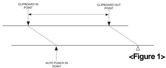
Due to this, as shown in Figure 2, in the case whereby data registered in the CLIPBOARD is the actual sound point and head of the measure is behind this, then even though you attempted to paste this head of the measure in alignment with this previously head, it will be pasted off alignment by this procedure due to the CLIPBOARD IN = ALIGN SEL function.
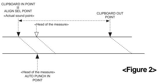
To align the head of the measure for pasting together with sound data in front of the measure, the "ALIGN SEL" function of VF160EX can be utilized. To use this function, the head of the measure data in the clip data must be registered in the [ALIGN SEL] key as shown in Figure 3.
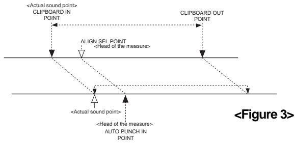
CLIPBOARD IN data, as a result of copy clip (or move clip), will be directly registered in the [ALIGN SEL] key. Next, recall the [ALIGN SEL] key data (press the [ALIGN SEL] key) and, after correcting this data to head point of the measure, press the [STORE] key and then the [ALIGN SEL] key. After this, by executing copy & paste (or move & paste), the aligned heads of the measures together with data in front of the measures, can be pasted.
The range in correction of the ALIGN SEL data must be strictly limited between CLIPBOARD IN-OUT.
Erase
The VF160EX provides the following "ERASE" options. Please read the instructions in its entirety prior to actual operations, to prevent any erroneous understanding of the description. First, start the desired program if there are several programs set. DO NOT change a program in the middle of the erase procedure.
Erasing a selected section between ABS - REC END.
A selected section between ABS 0 (beginning of disk) and REC END (REC end point) is erased of the program currently started up.
Both mono tracks and multiple tracks (including all real tracks) can be erased if assuming that they are real tracks. To erase data, it needs to first be on a real track.
When erasing a selected section between ABS 0 - REC END, END of recording point remains unchanged as shown in the figure below. Only the section erased of data (meaning there will be no sound on that section) will be erased. Once the data is erased there will be more disk space remaining on the disk (more storage space to save new data).
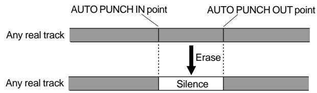
Erasing from a voluntarily specified point to REC END.
All data from a voluntarily specified point (other than ABS 0) to REC END is erased from the currently started program. Both mono tracks and multiple tracks can be erased, as in the case described to the left.
When erasing all tracks to REC END, the REC END point moves forward.
However, the REC END point may not move forward (Refer to on this page for more details) even when erasing data on multiple tracks that are not mono tracks or all tracks.
Note that the disk space remaining increases as in the case to the left, after data is erased from a section.
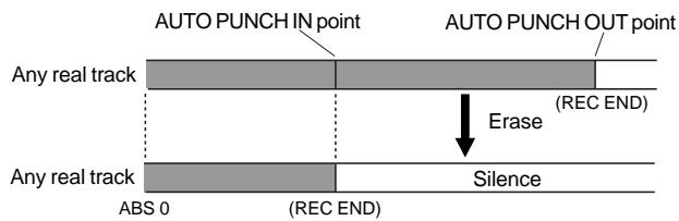
As in the case below, if data is recorded on real tracks 1 to 7, and data is erased from tracks 1 and 2, then the REC END, which the VF160EX recognizes, remains the same before and after erasing data.
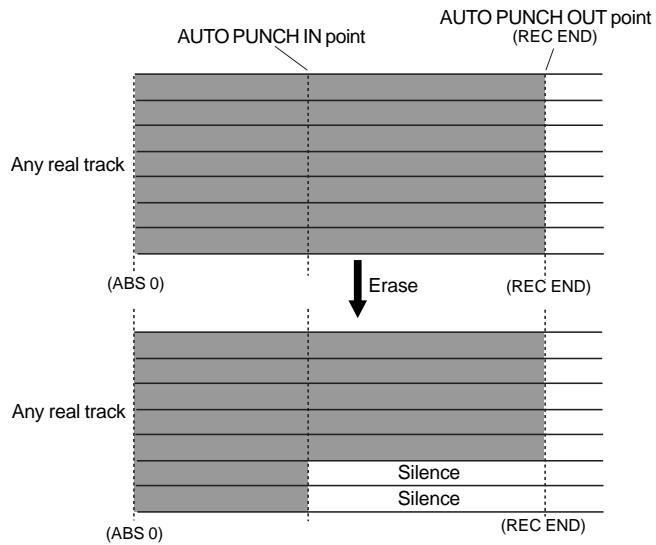
On the other hand, if data is erased from tracks 3 to 7 as shown in the figure below, the REC END point after erasing data will be positioned at the REC END point of tracks 1 and 2. In other words, the REC END point prior to erasing data moves, after the data is erased.
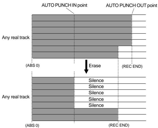
Erasing Data
- Set the starting point and ending point of the section to erase.
Set the starting point to erase to the [AUTO PUNCH IN] key, and the ending point to erase to the [AUTO PUNCH OUT] key. For more details on setting data to the memory key refer to page 34.
- Press the [EDIT] key in the STOP state. Then select "Erase?".
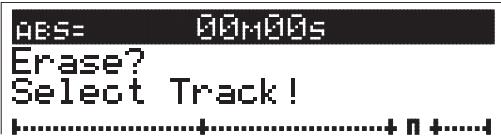
- Use the [CH STATUS/CH SEL] key to select the track to erase.
Mono tracks or multiple tracks (including all real tracks) can be selected to ERASE. The [CH STATUS/CH SEL] key of the track selected flashes.
4. Press the [ENTER/YES] key.
"Sure?" flashes.
![FOSTEX VF160EX - Press the [ENTER/YES] key. - 1](/content/2025/01/168450/images/7b4cf99f5993c02a5e16ef766b472b85fb49bf03baecc5f1f7ecf6c58058cc03.jpg)
5. Press the [ENTER/YES] key once again.
The erase process will takes place. "Wait Erasing!" flashes on the display while data is being erased. "Completed!" lights up on the display when the data is successfully erased.
6. Press the [EXIT/NO] key (or [STOP] key).
The LCD returns to the Normal Display prior to the editing mode.
To erase all data between ABS 0 and REC END, it is recommended that the time after REC END is set as the ERASE end point (AUTO PUNCH OUT point) to ensure that all the data is completely erased. In such case, move the current location of the recorder to the REC END point prior to setting the AUTO PUNCH OUT point and then press the [PLAY] key from that REC END point to move the REC END point slightly forward. Then press STOP. By setting that STOP point (time) to the [AUTO PUNCH OUT] key, it becomes possible to thoroughly erase all data from that section. The hard disk does not access any point after the REC END point, even when PLAY is started. When there is no data on that section, only the time will be counted.
UNDO/REDO Erase
The erase procedure can be undone and redone with the UNDO/REDO feature.
- Data eased can be undone (unerased) by pressing the [UNDO/REDO] key after ERASE. The data will return to the pre-erase status.
- The data erased but undone (unerased) can be redone (re-erased) by pressing the [UNDO/REDO] key immediately after undoing the erase process. The data will return to the post-erase status.
Note the following when executing the UNDO/REDO feature.
The UNDO/REDO feature is valid only when the recorder is in the STOP state.
UNDO/REDO is no longer possible if the following procedures take place after ERASE.
- When data is newly recorded.
- When data is newly edited.
- When the AUTO PUNCH mode is ON and PLAY (or RECORD) mode is effected, and the point has already passed the AUTO PUNCH IN point.
- When the power is turned OFF.
- When program selection takes place.
Track Exchange
"Track Exchange" allows the tracks currently on the program to be interchanged (all real tracks and additional tracks) on mono track or multiple track (2 tracks or 8 tracks each) units.
This function makes it possible to exchange real tracks. A real track can be emptied by moving a real track to a blank additional track. This means that real track can be recorded with other data. All-in-all, track exchange allows effective utilization of the tracks.
As already described in the "Erase" section, the "Track Exchange" feature is necessary to check the REC END point of an additional track.
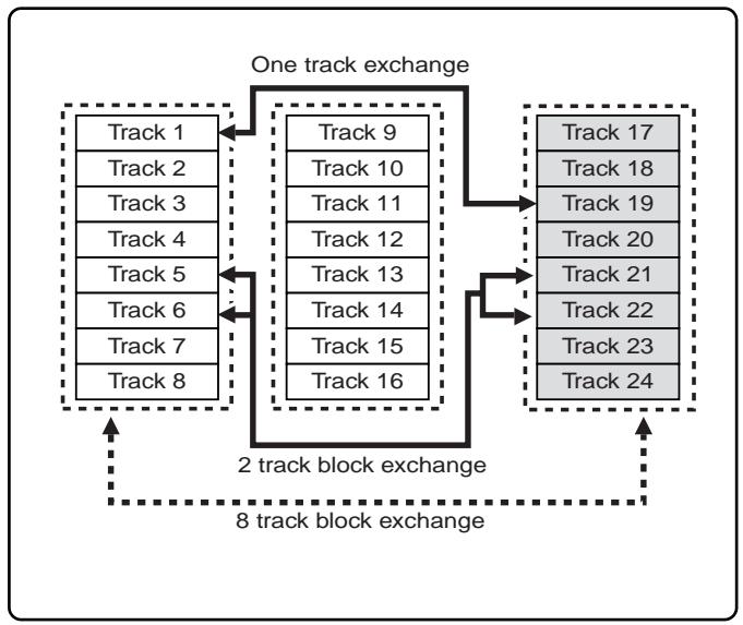
Executing Track Exchange
- Press the [EDIT] key while the recorder is in the STOP state, and show "Track Exchange?" on the display.
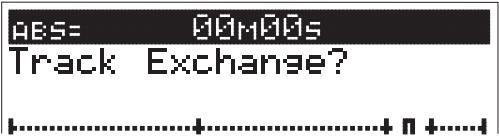
2. Next press the [ENTER/YES] key.
The track exchange selection display appears.
The current display indicates that track 1-8 and track 9- 16 can be exchanged in 8 track units.
To select another combination, go to the next step, respectively.
![FOSTEX VF160EX - Next press the [ENTER/YES] key. - 1](/content/2025/01/168450/images/b8d0919e4dbb45905a8c317510cdca9cd170aada4a8ad7e04fd9b2d50bdc28d2.jpg)
- Exchange in 8-track units
- While "01-08" on the left is flashing, press the [HOLD/>] or [F FWD] key to make "09-16" flashing.
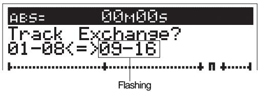
- Turn the [JOG] dial to select "09-16" or "17-24" to flash on the display.
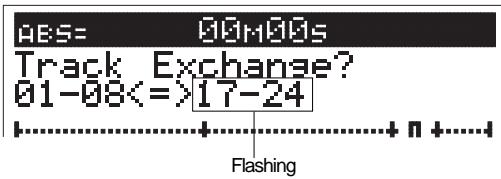
3. Press the [ENTER/YES] key.
The tracks are instantly exchanged.
"Completed!" appears on the display when the tracks are successfully exchanged. Then the LCD returns to the original time base display.
- Exchange in mono or 2-track units
1. Turn the [JOG] dial while "1-8" is flashing.
You can select among mono tracks (1 through 24) and stereo 2 tracks (1&2, 3&4, ..., 23&24), as well as 8 tracks. The right column shows the same unit, according to the selection on the left column as shown in the figure below. Therefore, you should select track(s) in the left column first and then select track(s) in the right column.
![FOSTEX VF160EX - Turn the [JOG] dial while "1-8" is flashing. - 1](/content/2025/01/168450/images/eb031e12eda17d2526f1ca002dc9bf7abfffa40c8de814c34e106d00b5f2b79e.jpg)
![FOSTEX VF160EX - Turn the [JOG] dial while "1-8" is flashing. - 2](/content/2025/01/168450/images/43c55164d7727714425e67cb3bed6a78acdea43cc7af4149cd03625c32ccaaa4.jpg)
- Press the [HOLD/>] or [F FWD] key to make the right column flash, and select the desired track(s) using the [JOG] dial.
The numbers on the right and left of mono tracks mean the same thing, therefore, the numbers can be reversed and still mean the same thing. In other words, "04<=01" and "01<=04" mean the same thing. This representation means that tracks 1 and 4 will be exchanged, regardless of which number comes first.
If you select the same track(s) for both the left and right columns (for example, "04<=04", "01&02<=01&02" or "01-08<=01-08"), you cannot carry out a track exchange. "Select Err" appears on the display and the display returns to the previous one.
3. Press the [ENTER/YES] key.
The tracks are instantly exchanged. "Completed!" appears on the display when the tracks are successfully exchanged. Then the LCD returns to the original time base display.
Chapter 5 Features Application
Applications of DIRECT RECORD
This section describes applications of the DIRECT RECORD feature.
DIRECT RECORD basically takes place with the play [TRACK] started for all the channel faders. However, it is also possible to start [INPUT] signals A to H. Here we will DIRECT RECORD to tracks 1 to 16, while monitoring the counter and listening to a rhythm machine (in this case, a drum machine) from input H.
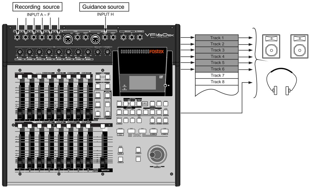
Connecting the sound source
- Connect the OUT of the drum machine to [INPUT] H.
- Connect the sound sources to record to [INPUT] A to F.
- Press the [INPUT SEL] key (ORANGE: Flashing).
- Press the [CH STATUS/CH SEL] key of ch16 so it flashes ORANGE (ch16-> INPUT).
- Press the [EXIT/NO] key to return to the Normal Display.
- Set the ch16 fader and master fader to "0".
- Start the drum machine and then adjust the [TRIM] of 8/16/H.
The input signals of [INPUT] H are output from the L/R stereo OUT. Use the [MON OUT] knob or [PHONES] knob to increase the volume to an appropriate level.
- Press the [DIRECT-RECTRK] key, then choose a track to record with the [CH STATUS/CH SEL] key. (RED: Flashing)
Press the [CH STATUS/CH SEL] key of ch1-ch 6 so tracks 1-6 will be READY.
- Press the [EXIT/NO] key to return to the Normal Display.
-
Set ch1-ch6 faders to "0".
-
Press the [RECORD] key and then set the READY track to input monitor (RED: Flashing).
By using the input monitor, it is possible to monitor the sound sources of ch1-ch6 and the INPUT H signals, at the same time. Set the PAN as desired so it is easy to monitor the sound.
- Adjust the [TRIM] of each channel while outputting the sound source.
Set the input level of each sound source, then proceed to the next REC process.
Record
- To start recording, press the [PLAY] key while the [RECORD] key is depressed.
Sounds are DIRECTLY RECORDED to tracks 1-6 according to the guidance sounds of input H.
- If the ch16 fader is set to "INPUT", then track 16 cannot enter READY status which means recording will not be possible. If, for example, all faders of ch9-ch16 are set to "INPUT", then recording is no longer possible on tracks 9-16. Note that this does not affect any signal already recorded on tracks 9-16.
- The fader of ch16 merely adjusts the level of the H [INPUT] signal sent to stereo OUT. Therefore, it does not adjust the level of the signals recorded.
Internal Mixdown Mode
Generally, "mixdown" means the process for mixing audio materials (instruments, vocals, etc.) recorded on a multitrack recorder and recording the stereo-mixed signals to a master (digital or analog) recorder.
The internal mixdown mode, allows you to mix 16 internal tracks recorded on a program down to stereo signals and record them to the current drive of the unit.
By using the internal mixdown function, you can make mixdown without the need for an external master recorder.
Furthermore, you can record an internally mixed material to a CD-RW/CD-R disc to make an audio CD. See page 125 for details.
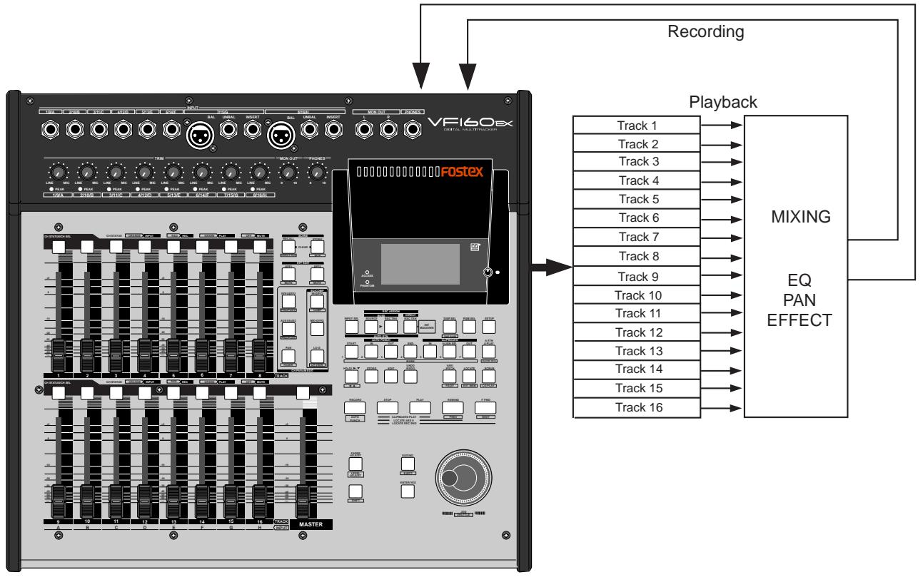
After executing mixdown, a new program on which a mixed-down material is saved is automatically created on the current drive. The program number of this program is set to one greater than the current greatest program number.
For example, if there are 8 programs (P01 through 08) on the current drive, by mixing down a desired program data, a new program (P09) is automatically created and the mixed-down stereo signals are recorded on tracks 1 and 2 of P09.
Note that if the unit is under either of the following conditions, you cannot carry out internal mixdown.
- There are 99 programs already existed on the current drive even though there is enough recording space.
If you try to carry out internal mixdown, "Can't New PGMI" is shown and the operation is ignored. To carry out mixdown, delete an unnecessary program.
- There is not enough recording space even though there are less than 99 programs on the current drive.
If you try to carry out internal mixdown, "Over time!" is shown and the operation is ignored. To carry out mixdown, erase unnecessary song data or delete an unnecessary program.
Activating the internal mixdown mode
1. Select the program to be mixed down.
To select the desired program, press the [PGM SEL] key and select the program using the [JOG] dial, then press the [ENTER/YES] key.
2. When the unit is stopped, press the [DIRECT RECTRK] key while holding down the [SHIFT] key.
See the illustration below.
![FOSTEX VF160EX - When the unit is stopped, press the [DIRECT RECTRK] key while holding down the [SHIFT] key. - 1](/content/2025/01/168450/images/c7a6d09ec12766f6ca4a1a183e4964a79c806a3a5025f0687240387e0c97a1a5.jpg)
The program number/name shown on the Normal display changes to "Int. Mixdown" in inverse video, showing that the internal mixdown mode is now active, while the [DIRECT REC TRK] key flashes.
In the example shown below, "P08: Song Data-1" is mixed down.
Each time you press the [DIRECT RECTRK] key while holding down the [SHIFT] key, the mixdown mode alternates on and off.
![FOSTEX VF160EX - When the unit is stopped, press the [DIRECT RECTRK] key while holding down the [SHIFT] key. - 2](/content/2025/01/168450/images/2c4d0cf527e5bd0872364f8799c66bf97c7ccd371f80ca4e6cf4c3f777ff56ca.jpg)
If you press the [DIRECT RECTR K] key to activate the internal mixdown mode when the recording track(s) or source track(s) are set for "DIRECT recording" or "BUSS recording", the following message ("Rec Mode Change!" and "Sure?") appears.
In this case, pressing the [ENTER/YES] key activates the internal mixdown mode.
Pressing the [EXIT/NO] key cancels the operation.
![FOSTEX VF160EX - When the unit is stopped, press the [DIRECT RECTRK] key while holding down the [SHIFT] key. - 1](/content/2025/01/168450/images/46ab33addbd9f12f360e9d14a7c6e1d53b91353d15ab331fa0ea2dfb15d84934.jpg)
After the internal mixdown recording is completed, the unit automatically quits the internal mixdown mode.
The unit also automatically quits the internal mixdown mode when you complete performing any of the following while the internal mixdown mode is active. Therefore, if you want to continue the internal mixdown mode, you need to activate the mode again.
- Program change
- Program delete
- Creating a new program
- Formatting a disk
- Copy/paste, Move/paste
- Erase
- Save to/load from DAT/adat
If "Rec Protect" in the Setup mode is set to "ON", you cannot carry out internal mixdown.
If you try to perform the internal mixdown operation, "Protected!" appears on the display.
In this case, set "Rec Protect" in the Setup mode to "OFF" before performing the internal mixdown operation.
Rehearsing internal mixdown recording
Before performing the actual mixdown recording, you can rehearse it while adjusting level, balance and sound character (EQ, effect, etc.) of each track.
In the following description, we assumes that you are going to mixdown all program tracks (1 through 16) on which instruments or vocals are recorded, and headphones for monitoring are connected to the [PHONES] jack.
Make sure that the [CH STATUS/CH SEL] keys of all the source and MASTER channels are lit (in the following example, all the [CH STATUS/CH SEL] keys should be lit). A channel whose [CH STATUS/CH SEL] key is unlit will not be mixed down.
1. Select the desired program to be mixed down.
To select the desired program, press the [PGM SEL] key and select the program using the [JOG] dial, then press the [ENTER/YES] key.
2. Set the [MASTER] fader to the "0" position.
3. Press the [PLAY] key to start playback from the beginning of the selected program.
4. During playback, adjust track levels using the channel faders, as well as pan, EQ and effect settings if necessary.
You can monitor the mix-down sound (in other words, stereo buss signals) through the headphones by raising the [PHONES] control. You can record the exact sound you are monitoring by executing the actual mixdown recording as described in "Performing internal mixdown recording".
You may playback the program repeatedly to tailor the sound by setting pan, EQ and effects until you are satisfied.
For details about setting pan, EQ and effects, see the "Chapter 3 Advanced mixer operations".
You can make internal mixdown recording with the "Scene sequence" function active. By executing the scene sequence after creating the scene event map, you can make mixdown recording while playing back materials according to the scene event map.
However, only the scenes that are set for the direct recording can be recalled by the scene sequence.
Note that the scenes that are set for the buss recording cannot be recalled.
5. After completing all the adjustments, stop the unit and locate the beginning of the program.
You can locate the beginning of the program (ABS 0) quickly by pressing the [REWIND] key while holding down the [STOP] key.
Now you are ready for actual internal mixdown recording.
In the internal mixdown mode, unlike the normal recording, you do not have to select recording tracks. When executing the internal mixdown recording according to the following procedure, the unit automatically arms Tracks 1 and 2. Therefore, the [CH STATUS/CH SEL] keys never light up in red during the internal mixdown recording.
- Press the [DIRECT REC TRK] key while holding down the [SHIFT] key to activate the internal mixdown mode. Make sure that the [DIRECT REC TRK] key flashes.
2. Press the [PLAY] key while holding down the [RECORD] key.
The internal mixdown recording starts.
Both the [DIRECT RECTRK] and [RECORD] keys light up.
![FOSTEX VF160EX - Press the [PLAY] key while holding down the [RECORD] key. - 1](/content/2025/01/168450/images/32239fba2cdc6292ed82cce410c92af25a277bfde3cf28c3bfc7904db4362bb4.jpg)
3. After completing internal mixdown recording, press the [STOP] key to stop the unit.
"Please Wait!" appears on the display for a few seconds. The internal mixdown mode quits and the unit locates the beginning (ABS 0) of the newly created (mixed-down) program.
In the display example below, you can see the newly created program, whose number is "P09", is mixed down from "Song Data-1" data.
We recommend to give a title of a mixed-down program starting by "Mix < - " to distinguish from other programs.
![FOSTEX VF160EX - After completing internal mixdown recording, press the [STOP] key to stop the unit. - 1](/content/2025/01/168450/images/18974634e737a83014da1de2af261fe656e2d267485f87afcb7a59e0b265d5d2.jpg)
4. Check the result by playing back the mixed-down program ("P09" in the example above).
The playback levels of mix-down tracks can be adjusted using faders for channels 1 and 2.
If you make an audio CD of the mixed material, read "Hint" on the next page in advance.
If you are not satisfied with the result, try again from the beginning.
You cannot undo internal mixdown recording.
If you do not need the previously recorded program, delete the program by using "Delete" menu in the Setup mode.
When internal misdown is completed, the starting and editing times of the misdown are registered as "CLIPBOARD IN point" and "CLIPBOARD OUT point" respectively (see the illustrations below).
This is because, when making an audio CD from the mixed-down material, data between "CLIPBOARD IN point" and "CLIPBOARD OUT point" is automatically recorded.
Regardless of the starting point of mixdown, only the data between "CLIPBOARD IN point" and "CLIPBOARD OUT point" is recorded when making an audio CD. In other words, you cannot make an audio CD without setting these two points.
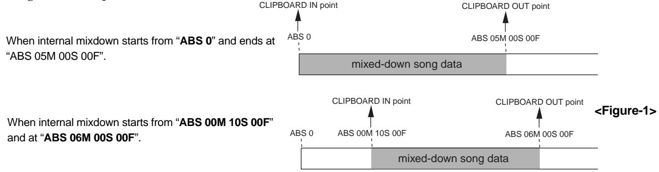
However, if you make an audio CD from the material whose actual audio starts from the exact "CLIPBOARD IN point", there will be no silence before starting audio.
If you want to make a CD which have a silence before actual audio starts, move back the mixed-down data for a few seconds as shown in Figure-2, or move ahead the "CLIPBOARD IN point" for a few seconds as shown in
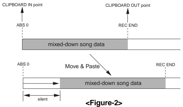
Figure-3.
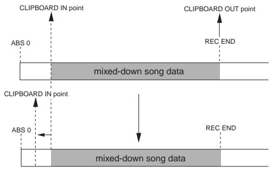
If you burn more than one mastered material which does not have "silent space" at the beginning and the end to a CD-R/RW disc, an audio CD that has no silent space between adjacent tracks is created.
Therefore, in such a case, create a silent space by either of the methods shown above. See the explanation from the next page for details about the actual operations.
When you move data as shown in Figure-2, the "CLIPBOARD IN point" is not changed, while the "CLIPBOARD OUT point" moves (as shown in Figure-4).
If you record data to a CD-RW or CD-R disc without changing the CLIPBOARD OUT point, data between the CLIPBOARD IN and OUT points is recorded but data between the CLIPBOARD OUT and REC END points are not recorded.
Therefore, you have to set the "CLIPBOARD OUT point" to the same point as the "REC END point" or latter point.
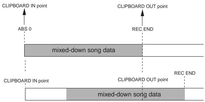
Inserting "silence" at the beginning of a song
To insert "silence" at the beginning of a song, use either of the following methods depending on the start time.
The following operations are assumed to be done when the time base is set to "ABS".
If you want to perform the operations with another time base (such as Bar/Beat), press the [DISP SEL] key while holding down the [SHIFT] key to change the time base in advance.
When mixdown starts from "ABS 0"
You can make a silence at the beginning of a program which is mixed down from "ABS0" by using the "move & paste" technique.
In the following description, we assumed that the current program is a 5-minute length program, in which the [CLIPBOARD IN] and [CLIPBOARD OUT] keys hold "00M 00S 00F 00SF" and "05M 00S 00F 00SF" respectively, and audio immediately starts from ABS 0 (=00M 00S 00F 00SF).
And you are now going to create a 3-second silent space at the beginning of the program.
- First, enter the "AUTO PUNCH IN" point, which is the destination for the paste operation.
1. At the beginning of the program (ABS 0), press the [HOLD/>] key.
The current time is held and "S" on the display flashes, showing that you can now edit the "second" field.
![FOSTEX VF160EX - At the beginning of the program (ABS 0), press the [HOLD/>] key. - 1](/content/2025/01/168450/images/c37899a7ed5f79c5d6b5e256b75d1d4184df7e250fb43e67ef4e3189b95b39bf.jpg)
2. While "S" flashes, enter "03" using [JOG] dial and press the [STORE] key.
"Hit Any Memory Keys!" appears on the display.
![FOSTEX VF160EX - While "S" flashes, enter "03" using [JOG] dial and press the [STORE] key. - 1](/content/2025/01/168450/images/2fc3ec8d6d658516ac0f90472608207ae8f7d2ffe050e04458bb63cd8ed182c8.jpg)
To edit another field than "second", use the [HOLD/>] key (or [REWIND]/[F FWD] keys) to flash the appropriate point.
3. Press the [AUTO PUNCH IN] key.
Now the [AUTO PUNCH IN] key holds "00M 03S 00F 00SF" as the auto punch-in point, and the display returns to the Normal display.
- Then carry out the move & paste operation.
4. After pressing the [EDIT] key, use the [JOG] dial to display "Move Clip?".
"Select Track!" appears together with "Move Clip?".
![FOSTEX VF160EX - After pressing the [EDIT] key, use the [JOG] dial to display "Move Clip?". - 1](/content/2025/01/168450/images/3d19b3cd194548227004ca7cbdea8f01e110db0927581c436368444edcb1fc77.jpg)
5. Press the [CH STATUS/CH SEL] keys of channels 1 and 2.
These [CH STATUS/CH SEL] keys that start flashing in red, showing that tracks 1 and 2 are selected to be moved.
6. Press the [ENTER/YES] key.
The "move" operation is immediately completed, and "Move Paste?" appears on the display.
![FOSTEX VF160EX - Press the [ENTER/YES] key. - 1](/content/2025/01/168450/images/7cc91333908014cbba5cf1926298ff39cde25ae58e832047c073707cfe983f15.jpg)
7. Press the [ENTER/YES] key again.
The display for selecting the number of repeat times appears, in which "01" and "Sure?" flash.
In this tutorial, leave the number as the initial "01".
![FOSTEX VF160EX - Press the [ENTER/YES] key again. - 1](/content/2025/01/168450/images/7b17f1ada7c6125cf91ad888c83ccf69b2687f846aa3c04a613d5988bf98ecf4.jpg)
8. Press the [ENTER/YES] key again while "01" flashes.
The move & paste operation is immediately completed and the program data now moved as shown below. When the move & paste operation is completed, "Completed!" appears on the display.
![FOSTEX VF160EX - Press the [ENTER/YES] key again while "01" flashes. - 1](/content/2025/01/168450/images/faffadb80af05fefa190beef6897c92c81fd6a515b9875a1d63cde1bc851150b.jpg)
As we mentioned earlier, if you make an audio CD in this condition, data after the "CLIPBOARD OUT point" will not be recorded.
Therefore, you have to set the "CLIPBOARD OUT point" to the "REC END point".
- Change the "CLIPBOARD OUT point".
- When the unit is stopped, press the [F FWD] key while holding down the [STOP] key.
The unit immediately locates the "REC END point".
- Press the [STORE] key followed by the [CLIPBOARD OUT] key.
The "REC END point" is now registered as the "CLIPBOARD OUT point".
The display returns to the Normal display.
By changing the "CLIPBOARD OUT point", you can now create an audio CD without loosing the last part.
When mixdown starts from non-“ABS 0”
You can make a silence at the beginning of a program which is not mixed down from "ABS 0" by setting the "CLIPBOARD IN point" appropriately.
In the following description, we assumed that the current program is a 5-minute length program which is mixed down from "ABS 00M 10S 00F 00SF", in which the [CLIPBOARD IN] and [CLIPBOARD OUT] keys hold "00M 10S 00F 00SF" and "05M 10S 00F 00SF" respectively, and audio immediately starts from "00M 10S 00F 00SF".
And you are now going to create a 3-second silent space at the beginning of the song.
- Change the "CLIPBOARD IN point".
- When the unit stopped, press the [CLIPBOARD IN] key.
The time registered with the [CLIPBOARD IN] key is shown (in this tutorial, "ABS 00M 10S 00F 00SF"), and "s" on the display flashes, showing that you can now edit the "second" field.

-
While "S" flashes, enter "07" using the [JOG] dial.
-
Press the [STORE] key followed by the [CLIPBOARD IN] key.
"00M 07S 00F 00SF" is registered with the "CLIPBOARD IN point".
Now you made a 3-second silent space at the beginning of the song by changing the "CLIPBOARD IN point".
See "Making an audio CD" in "Save/load using CD-RW/CD-R" described later for details about how to make an audio CD from the mixed-down song.
Applications of BUSS RECORD
BUSS RECORD makes it possible to record all the source channel signals sent to REC BUSS L/R on either 2 tracks or 1 track. The source channel is selectable with the "IN (Input)" channel and "TRK (Track)" channel, therefore, it is possible to record the input signals along with signals that are already recorded.
Here, we will mix the play sounds of tracks 1-4 with the signals input through [INPUT] A-D to record on tracks 7 and 8. Sound sources

Connecting the sound source
- Connect the sound sources to record to [INPUT] A to D.
Preparations to record
- Press the [INPUT SEL] key (ORANGE: Flashing). The display to select "IN (Input)" - "TRK (Track)" appears.
- Press the [CH STATUS/CH SEL] key of ch9-ch12 so it flashes ORANGE (ch9-ch12 -> "IN (Input)").
- Press the [BUSS-SOURCE] key (GREEN: Flashing). The display to select the source channel appears.
- Press the [CH STATUS/CH SEL] key of ch1-ch4 and the [CH STATUS/CH SEL] key of ch9-ch12. Ch1-4 and ch9-12 are set to the source channel.
- Press the [BUSS-RECTRK] key (RED: Flashing). The display to select the REC track appears.
- Press the [CH STATUS/CH SEL] key of ch7 and ch8. Ch7 and ch8 are set as the REC track. The signals from ch1-4 and ch9-12 can not be recorded to tracks 7 and 8.
- Press the [EXIT/NO] key to return to the Normal Display.
- Set the ch1-4, ch 7&8, and ch9-12 fader and master fader to "0".
- Press the [RECORD] key to go to the input monitor (RED: Flashing).
- Set the ch7/8 fader and PAN that is used to monitor the REC track.
Set the ch7 PAN to the LEFT (L) and ch8 PAN to the RIGHT (R). The position of the recorded signal can be checked.
- Adjust the faders, PAN, equalizer and effect of each source channel (ch1-4 and ch9-12).
The sound is recorded on track 7 by setting the source channel PAN to the LEFT. The sound is recorded on track 8 by setting the source channel PAN to the RIGHT. The sound is recorded on both tracks by setting the source channel PAN to the CENTER.
When the preparations to record have been completed, start recording according to the basic "BUSS RECORD" instructions described earlier.
Tips: How to adjust the REC BUSS Master Level
To adjust the REC BUSS Master Level, press the [BUSS-RECTRK] key then use the [JOG] dial while the following display is shown. The default setting of the REC BUSS Master Level is set to "80". However, this can be modified to a voluntary REC BUSS Master Level with the [JOG] dial. After adjusting the level, press the [EXIT/NO] key.
The Normal Display appears. The master level during recording appears on the level meter shown on the display below.
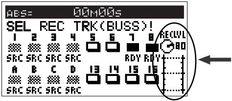
Ping-Pong RECORD
By using BUSS RECORD, it is possible to select a maximum of 15 source channels when recording to 1 track and a maximum of 14 source channels when recording to 2 tracks. Here we will ping-pong record the sound recorded on tracks 1-14 onto tracks 15 and 16 for temporary mix down. Ping-pong RECORD refers to the process in which the sound of several tracks are mixed and then recorded on another track.
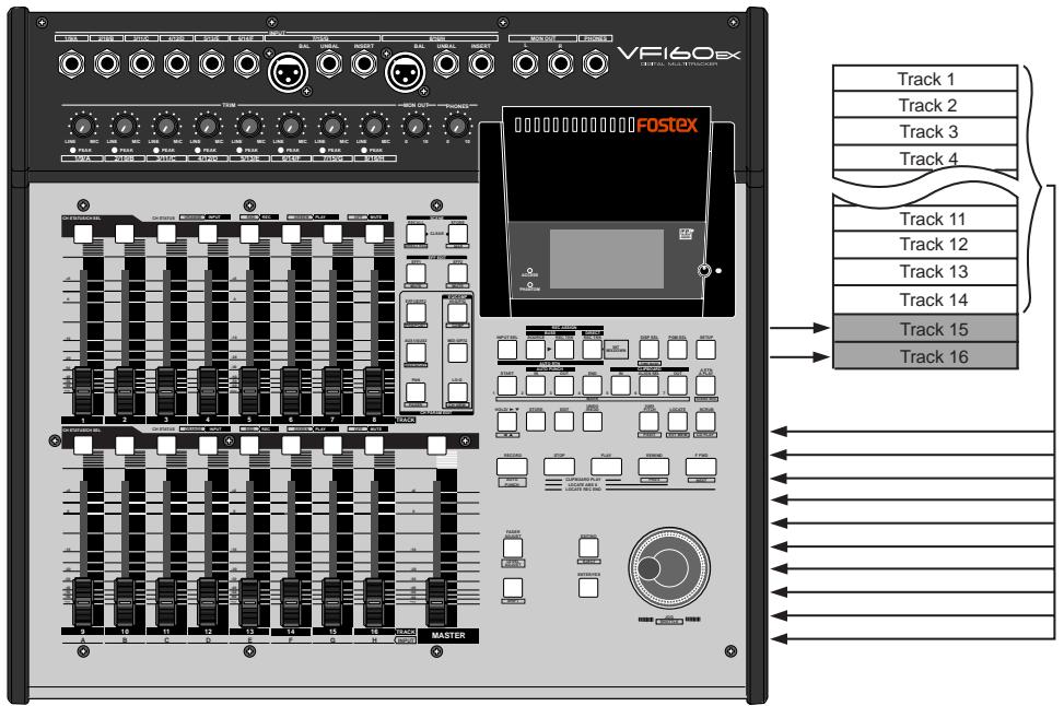
Preparations to record
- Press the [INPUT SEL] key (ORANGE: Flashing). The display to select "IN (Input)" - "TRK (Track)" appears.
- Press the [CH STATUS/CH SEL] key of ch9-ch16 so it flashes GREEN (= "TRK (Track)").
- Press the [BUSS SOURCE] key (GREEN: Flashing). The display to select the source channel appears.
- Press the [CH STATUS/CH SEL] key of ch1-ch14. Ch1-8 and ch9-14 are set to the source channel.
- Press the [BUSS-RECTRK] key (RED: Flashing). The display to select the REC track appears.
- Press the [CH STATUS/CH SEL] key of ch15 and ch16 (RED: Flashing). Tracks 15 and 16 are set to the READY track.
- Press the [EXIT/NO] key to return to the Normal Display.
- Press the [RECORD] key to go to the input monitor (RED: Flashing).
- Set the ch15/16 fader and PAN that is used to monitor the REC track. Set the ch15 PAN to the LEFT (L) and ch16 PAN to the RIGHT (R). The position of the recorded signal can be checked.
- Adjust the faders, PAN, equalizer and effect of each source channel (ch1-14 and ch9-12).
The sound is recorded on track 15 by setting the source channel PAN to the LEFT.
The sound is recorded on track 16 by setting the source channel PAN to the RIGHT.
The sound is recorded on both tracks by setting the source channel PAN to the CENTER.
- To start recording, press the [PLAY] key while the [RECORD] key is depressed.
Tips: How to adjust the REC BUSS Master Level To adjust the REC BUSS Master Level, press the [BUSS-RECTRK] key then use the [JOG] dial while the following display is shown. The default setting of the REC BUSS Master Level is set to "80". However, this can be set to a voluntary REC BUSS Master Level with the [JOG] dial. After adjusting the level, press the [EXIT/NO] key. The Normal Display appears. The master level while recording appears on the level meter shown on the display below.
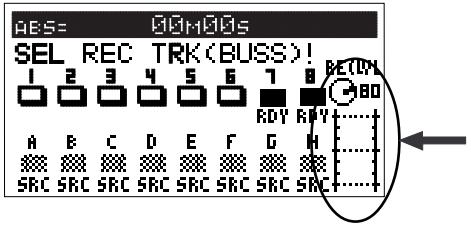
Metronome Function
The VF160EX incorporates a tempo map to set a desired bar/beat (4/4, 3/4, etc.) and tempo (30-250). It is possible to output a metronome sound, according to the setting of the tempo map. This allows for recording in sync with the rhythm output from the VF160EX without having to use an external metronome or rhythm box.
Setting the tempo map
The user must first set the tempo map to output metronome sound. The tempo map can be set through the "Beat Setting" menu and "Tempo Setting" menu of the SETUP mode. The default setting of the tempo map is set to 4/4 bar/beat with a tempo of 120. The following procedures are unnecessary if the default setting does not have to be modified. The tempo map of the default setting means that the metronome sound will always click at a 4/4 beat and 120 tempo.
- Press the [SETUP] key when the VF160EX is in the STOP mode, to go to the SETUP mode.
The display to select a SETUP menu appears.
- Use the [JOG] dial to select the "Signature Set" menu, then press the [ENTER/YES] key.
The menu to set the beat appears. Refer to "Setting the Beat" on page 99 for more details on how to customize the beat setting.
- After setting the beat, press the [EXIT/NO] key to return to the SETUP menu.
- Use the [JOG] dial to select the "Tempo Set" menu, then press the [ENTER/YES] key.
The menu to set the tempo appears. Refer to "Setting the Tempo" on page 135 for more details on how to customize the tempo setting.
- After setting the tempo, press the [EXIT/NO] key to return to the SETUP menu.
Next, proceed with the "Setting Metronome Output" procedure.
Setting metronome output
The next step is whether to set the system to output metronome sound or not. This is done in the same manner as setting the tempo map and is set from the "Metronome Function Setting" menu in the SETUP mode.
- Use the [JOG] dial to select the "Click?" menu, then press the [ENTER/YES] key.
The currently set item (On or Off) flashes.
The default setting is set to "Off".
- Use the [JOG] dial to select "On" (flashing), then press the [ENTER/YES] key.
The metronome function is now turned "On".
- When the setting has been completed, press the [EXIT/NO] key twice to escape from the SETUP mode.
Set the time base to the BAR/BEAT.
- Press the [DISP SEL] key while the [SHIFT] key is depressed to switch the time base display to the "BAR/BEAT" display.
It is possible to check the bar/beat set in the tempo map by switching to the "BAR/BEAT" display.
Checking metronome sound
- Press the [PLAY] key to play the VF160.
The metronome sound level appears on the level meter of ch16. At this time, turn up the master fader and fader of ch16 to "0", then use the [PHONES] knob or [MON OUT] knob to turn up the volume, to monitor the metronome sound.
It is possible to output the metronome sound from ch16 as described above. It is also possible to use the metronome sound as a guide to record to ch1-15.
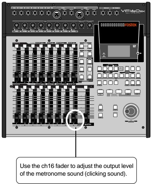
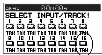
The metronome sound (clicking sound) cannot be heard unless ch16 is set to "TRK (Track)".
Press the [INPUT SEL] key to see that ch16 is set to "TRK", as shown in the display on the left.
When the metronome function is no longer necessary, always go to the SETUP mode to turn OFF the metronome function.
As long as the metronome function is ON, it is not possible to record on track 16, and any sounds already recorded on track 16 cannot be played.
Digital Recording
This section will describe digital recording from external digital devices using the [DATA IN] connector of the VF160EX. Digital signals recorded are either S/P DIF or adat digital signals.
Digital recording from an external digital device
This section describes digital recording methods from external S/P DIF digital devices (CD, MD, DAT, etc.) or adat digital devices (Fostex D1624mkII, D824mkII, VC-8, etc.) into the VF160EX.
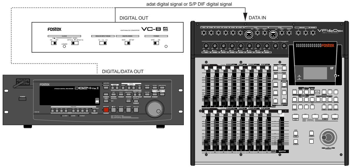
To digitally record to the VF160EX, only input digital signals (S/P DIF or adat) with the same sampling rate (44.1kHz/16bit) as the VF160EX.
Selecting the program to record
If several programs are set, use the program selection function to pre-start the program to record.
For more details on setup procedures refer to the "SETUP Mode" on page 141.
Set the "Digital In" (SPDIF) of the SETUP mode, as shown as an example below. With this setting the LEFT channel of the S/P DIF digital signal is recorded on track 1 and the RIGHT channel is recorded on track 2.
As shown in this case, when selecting a S/P DIF digital signal it is possible to set odd and even tracks next to each other.
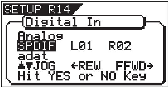
Set the "Digital In" of the SETUP mode to "adat".
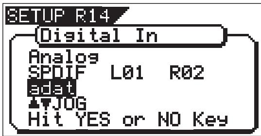
This setting records the adat digital signals on ch1-ch8 on tracks 1-8. In other words, the ch1 signals are recorded on track 1, ch2 signals on track 2, and so on. Simply put, the digital signal is recorded on tracks corresponding to the adat digital signal channel.
2. When the "Digital In" settings are completed, press the [EXIT/NO] key to escape from the SETUP mode.
The LCD shows the Normal Display.
Either “0081” or “5F0F” lights up on the display, when proper digital signals (S/P DIF or adat) from an external digital device is input in DATA IN.
If either “AOAT” or “SPCIF” flashes on the display it means that the digital signal input is incorrect. In such case check the connection cable and digital output setting of the external device.
Do not make connections such as for input of S/P DIF digital signals into the VF160EX DATA IN connector when "Digital In" is set to "adat". It could result in abnormal symptoms such as reduction in operating speed of VF160EX and also create noise.
Selecting a track to record
Digital recording is only an option of "DIRECT RECORD" that was described in the section on basic recording choices. It is not possible to apply equalization or effect on the signals recorded.
- Press the [INPUT SEL] key. Check to see that ch9-ch16 are all set to "TRK".
If any channel is set to "IN", modify the setting to "TRK".
- Press the [DIRECT-REC TRK] key.
The display to select the REC track appears.
- Press the [CH STATUS/CH SEL] key of the track that was set with "Digital In".
The [CH STATUS/CH SEL] key of the channel selected flashes RED.
- Press the [EXIT/NO] key to return to the Normal Display.
Starting to record
- Turn up the channel fader and master fader corresponding to the track recorded to "0".
- Press the [PLAY] key while the [RECORD] key is depressed to start recording with VF160EX, as well as start playing the external digital device.
The level meter of the digital signal level that is currently input will appear. There is no need to adjust the input level on the VF160EX for digital recording.
- Turn up the [PHONES] knob or [MON OUT] knob to monitor the sound.
- When recording is completed, press the [STOP] key to stop the VF160EX and to stop the external digital device.
If the track for digital recording is set from the "Digital In" menu of the SETUP mode, then tracks not assigned for digital REC can record analog signals at the same time.
For example, if S / P DIF digital signals are recorded on tracks 1 and 2, it would then be possible to record analog signals on the remaining tracks 3-16.
With this function, it is possible to simultaneously record 16 tracks with adat digital and analog signals.
However, the prerequisite is that "DIRECT RECORD" is the recording option being used. For further details, refer to the section on "Recording 16 Tracks at the Same Time" described below.
Recording 16 Tracks at the Same Time
This section describes how to simultaneously record a total of 16 tracks consisting of 8 analog signals and 8 adat digital signals. Simply put, tracks 1-8 record the adat digital signals from VC-8 or D824mkII and tracks 9-16 DIRECT RECORD the 8 analog signals.
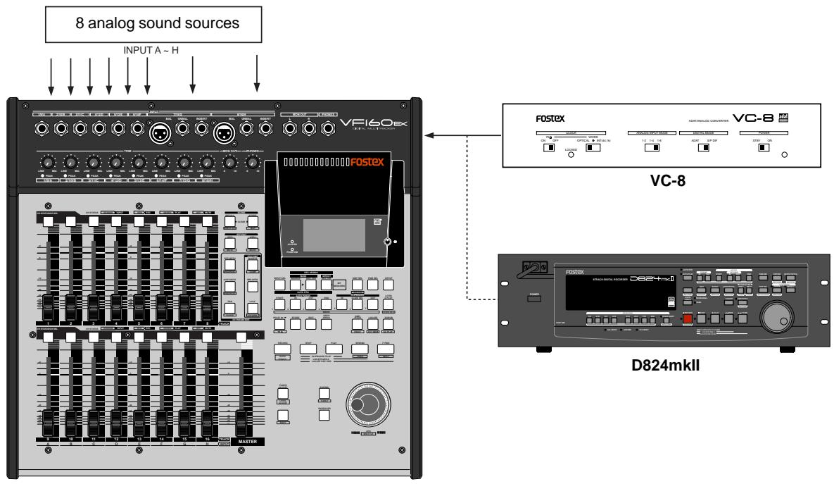
Connecting a Sound Source or External Device
- Connect the VC-8 or D824mkII to the [DATA IN] jack of the VF160EX.
- Connect 8 sound sources into [INPUT] jacks A to H.
Setting the VC-8 or D824mkII
- Set the VC-8 or D824mkII so it outputs adat digital signals. For more details refer to the VC-8 or D824mkII User's Manual.
Setting "Digital In" on the VF160EX
- Set the "Digital In" menu in the SETUP mode to "adat". For more details refer to the SETUP mode on page 141.
REC Track and Master Fader settings
- Press the [INPUT SEL] key.
Check to see that ch9-ch16 are set to "TRK(Track)". If there is any channel that is set to "IN (Input)" switch it to "TRK".
- Press the [DIRECT-RECTRK] key, so all tracks are READY.
The REC track selected will appear on the display.
- Press the [CH STATUS/CH SEL] key of ch1-ch16 so all tracks are READY.
Now the adat digital signals (ch1-ch8) from VC-8 (or D824mkII) are recorded on tracks 1-8 and the input signals from [INPUT] A to H are recorded on tracks 9-16.
- Press the [EXIT/NO] key and return to the Normal Display.
If normal adat digital signals from VC-8 (or D824mkII) are input into VF160EX, “2031” lights up on the Normal Display.
- Set the master fader to "0".
Check adat signal and adjust monitor
- Press the [RECORD] key.
All tracks go to the input monitor status.
If signals are input from the VC-8 (or D824mkII) in this state, the input level appears on the level meters 1-8.
To monitor the adat signals, turn the ch1-ch8 channel fader up to "0", and then turn up the [MON OUT] knob or [PHONES] knob.
There is no need to adjust the REC level on the VF160EX. The channel fader procedures only adjust the monitor sound.
- Set the channel fader of ch9 - ch16 to "0".
- Adjust the input level with the [TRIM] for which each sound source is input.
Fine tune the input with the channel fader if necessary. The monitor sound can also be heard at this time.
Starting to record
- To start recording, press the [PLAY] key while the [RECORD] key is depressed.
When recording starts, the adat digital signals from VC-8 (or D824mkII) are input along with the signal input of the analog sound source.
This allows recording of 8 analog signals (8 channels) and 8 adat digital signals (8 channels) for recording on 16 tracks at the same time.
MIDI Clock Sync System
By setting any desired meter at any desired point of the programmable tempo map contained in the VF160EX, and by output of a MIDI clock and song position pointer according to the setting, a hardware type MIDI sequencer can be synchronized as a MIDI clock slave. Consequently, in this system, the VF160EX will be the master and the MIDI sequencer the slave.
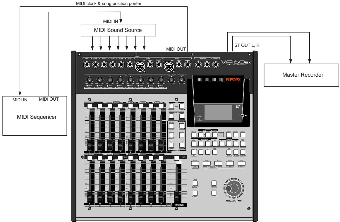
Connecting external equipment
- Connect the VF160EX MIDI OUT to MIDI IN of the MIDI sequencer.
- Set the MIDI sequencer for "external sync mode (EXTERNAL SYNC) by MIDI clock."
Refer to the Owners Manual of the equipment in use for details.
Setup of the VF160EX
- Because the MIDI clock and song position pointer will be output from the VF160EX, set the SETUP mode "MIDI sync signal output setting" to "CLK."
Refer to page "137", SETUP mode "MIDI sync signal output setting" for correct operating procedures.
- The meter in the desired bar can be set by "Time signature setting" of the SETUP mode.
Refer to page "133", SETUP mode "Time Signature Setting" for operating procedure.
- Tempo in the desired bar can be set by "Tempo setting" of the SETUP mode.
Refer to page "135", SETUP mode "Tempo Setting" for operating procedure.
- Set the SETUP mode "Metronome setting" to "On" if click sound is to be output according to the setup tempo map.
Refer to page "136", SETUP mode "Metronome setting" for operating procedure.
- Press the [DISP SEL] key while holding down the [SHIFT] key, and then change the time base display to BAR/BEAT/CLK.
Confirming the MIDI clock sync
During recording and at playback following the recording, the time base (BAR/BEAT/CLK) is displayed in accordance to the setup tempo map, and the MIDI clock and song position pointer is also output.
Confirm that the travel position (BAR/BEAT/CLK) of the VF160EX and the travel position of the synchronized MIDI sequencer are matched.
If correct sync cannot be obtained, re-check the connections/ cables and setting of both equipment.
In the VF160EX, the "ABS 0" position is set at "-002BAR/1BEAT/00CLK." This setting is made in consideration of the time required (it will not sync immediately) for the MIDI sequencer, etc. to enter into sync. As a result, if the VF160EX is played back from ABS 0 (LOCATE ABS 0), sync will be completed by the time it reaches the first bar, and will thus synchronize from head of the tune.
Execution of recording
Various ways of recording can be conducted while synchronizing the VF160EX and the MIDI sequencer with the MIDI clock.
MTC Sync/MIDI Machine Control System
The following will explain synchronization by the MTC (MIDI time code) output and the computer controlling system using MMC (MIDI machine control). In this system, the VF160EX will be the master and the computer (with sequence software) will be the slave. The VF160EX will attach any desired offset (time difference) against ABS time (absolute time) and output it as MTC in any desired frame rate. It can also carry out the proper operation upon receiving an MMC from outside. In this case, because the VF160EX can setup a DEVICE ID number by the SETUP mode "MIDI Device ID Setting" menu, a multiple number of the VF160EX's can be separately controlled by changing the DEVICE ID numbers in the transmitted message from the computer.
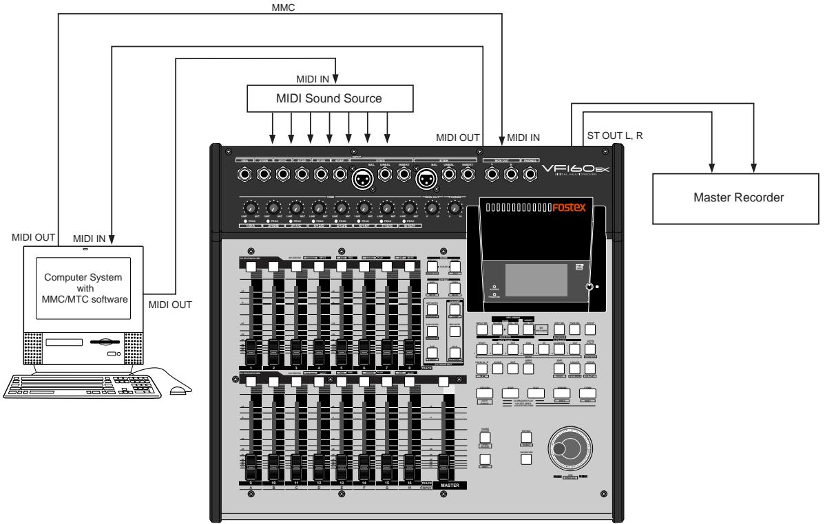
Connecting to external equipment
- Connect the VF160EX MIDI IN/OUT to the computer (with MIDI interface) MIDI IN/OUT.
MMC/MTC complied sequence software is activated in the computer.
Setup of external equipment
-
Setup the following in the sequence software.
-
Set to MTC external sync mode (EXTERNAL SYNC).
- Set for output of MMC.
- Set to the desired MTC read out frame rate.
- Set start time of the tune (which MTC time is to be the first bar). Refer to precaution in regards to MTC offset, farther on.
For details, refer to Owners Manual of the external equipment.
Setup of the VF160EX
- Because MTC will be output from the VF160EX, set to "MTC" the SETUP mode "MIDI sync signal output setting." Refer to page "137", SETUP mode "MIDI sync signal output setting" for operating procedure.
- Set a random offset time by the SETUP mode "MTC offset time setting."
Refer to page "138", SETUP mode "MTC offset time setting" for operating procedure.
3. In the SETUP mode "MTC offset mode setting," whether the MTC offset time setup in Step 2 should be output (ABS) at the ABS 00m 00s 00f 00sf position or at the 001BAR 1BEAT 00CLK (bar, signature) must be selected.
Refer to page "139", SETUP mode "MTC offset mode setting" for operating procedure.
4. Setup to the same frame rate as that setup by the sequence software by "MTC Frame rate setting" of the SETUP mode.
Refer to page "138", SETUP mode "MTC Frame rate setting" for operating procedure and details.
5. Set to the same figure as the sequence software MMC device number by the SETUP mode "MIDI device ID setting."
When the sequence software transmits by "7F", it means "ALL DEVICE" and therefore, it need not be setup. Refer to page "143", SETUP mode "MIDI device ID setting" for operating procedure and details.
6. Press the [DISP SEL] key while holding down the [SHIFT] key to show time base in the MTC display.
By "MTC offset time setting" and "MTC offset mode setting," at what position (ABS 0 or 001BAR/1BEAT/OOCLK) should the setup MTC (MTC offset time) is to be output is set. When setting the start time of the tune in the sequence software by these setups, be careful of the following points.
* Offset mode: For ABS
If playback is started from ABS0, since MTC will be output starting from the MTC offset time that has been set, the start time of the tune set by the sequence software must be set about 3 seconds later from the MTC offset time that was setup. This will provide time because the sequence software cannot sync immediately after MTC is output. For example, if the initial setting of 00h 59m 57s 00f 00sf" is used, set the start time of the tune to "01h 00m 00s 00f."
If playback is thus started from ABS O (LOCATE ABS O), sync will be obtained by the time it reaches the first bar and therefore it can be made to sync from the head of the tune.
* Offset mode: For BAR
As mentioned before, because the "ABS 0" position is set at the "002BAR/1BEAT/00CLK" position, the setup MTC offset time can be set to the head of the tune without taking into account the time until reaching sync, as mentioned above. The length of the time two bars beforehand will change in accordance to the first bar setting for "signature" and "tempo." For example, it will be long if the tempo is set slow. This mode can be effectively applied when using the MIDI clock and MTC in parallel, and when using MTC for the sync signal while controlling the recorder with time base BAR/BEAT/CLK.
Confirming MTC sync/MMC
- During recording and at playback after recording, time base MTC is displayed according to the setting and MTC is output at the same time.
Check that the VF160EX traveling position (MTC) and the traveling position of the sequence software in sync are matched.
- Send MMC commands such as PLAY, STOP and LOCATE from the sequence software to see that the VF160EX will be properly controlled.
When a correct MIDI command (MMC) is received, "MIDI" in the display will be lit for about 40msec. There is no setting in the VF160EX to receive MMC but it will operate if a correct MIDI signal is input.
If sync and control cannot be done correctly, re-check connections/cables and the setting of both equipment.
Execution of recording
Carry out various recordings while synchronizing the VF160EX and a MIDI sequencer with the MIDI clock.
External MIDI Equipment Sync System by the Slave mode
Up to this point, synchronization with external MIDI equipment has been explained with the VF160EX as the master and MIDI equipment as the slave but depending on the slave mode setting, the MIDI equipment can be set as the master and the VF160EX as the slave.
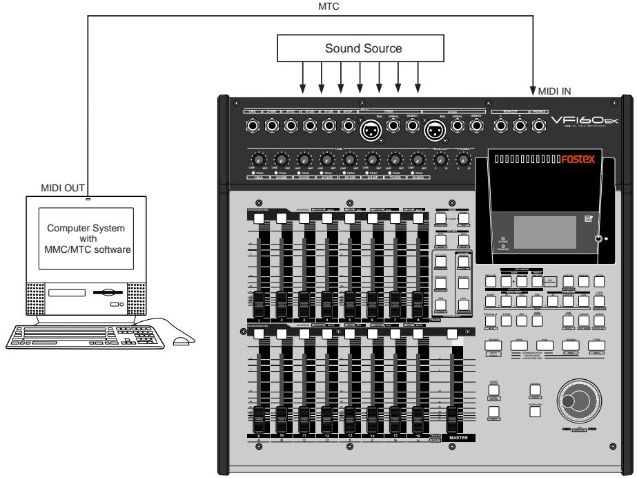
Connection to external equipment
- Connect MIDI OUT of the computer (with MIDI interface) with MIDI IN of the VF160EX.
The computer sequence software complying to MMC/MTC must be activated.
Setup of external equipment
-
Sequence software is setup as follows.
-
Set for output of MTC.
- Set frame rate of the MTC to be output.
- Confirm start time of the tune.
Refer to Owners Manual of the respective equipment for details.
Setup of the VF160EX
- Set to same frame rate as the sequence software by the SETUP mode "MTC Frame rate setting."
Refer to page "138", SETUP mode "MTC Frame rate setting" for operating procedure and details.
- Set to the desired mode by the SETUP mode "MTC offset mode setting."
Refer to page "139", SETUP mode "MTC offset mode setting" for operating procedure and details.
- A random offset time can be set by the SETUP mode "MTC offset time setting."
Refer to page "138", SETUP mode "MTC offset time setting" for operating procedure and details.
- Set slave mode to "On" by the SETUP mode "Slave mode setting."
Refer to page "139", SETUP mode "Slave mode setting" for operating procedure and details.
- Set slave type to "Vari" by the SETUP mode "Slave type setting."
Refer to page "140", SETUP mode "Slave type setting" for operating procedure and details.
- Press the [DISP SEL] key while holding down the [SHIFT] key, to change the time base display to MTC.
The position (ABS 0 or 001BAR/1BEAT/00CLK) when the setup MTC (MTC offset time) should be output was setup by the "MTC offset time setting" and "MTC offset mode setting." In accordance to start time of the tune set by the sequence software, setup as explained below.
- Offset mode: For ABS
Set the MTC offset time about three seconds prior to the start time of the tune set by the sequence software. Because the recorder cannot immediately chase lock after input of MTC, in order to sync the unit from head of the tune, set the preroll using the sequence software, and playback from before the actual head of the tune to allow the recorder to enter into sync by the time it arrives at the head of the tune.
- Offset mode: For BAR/BEAT
The MTC offset time can be set to the same time as the start time of the tune set by the sequence software. Because the "ABS0" position is set at the "002BAR/1BEAT/00CLK" position in the unit, as mentioned before, the preceding time required for sync is already set.
The preceding time of two bar lengths could change in length depending on the first bar's "signature setting" and "tempo setting" mentioned before. For example, it will be longer if the tempo is slowed down.
Confirming chase lock
- When the sequence software is played, "CHASE" and "MTC" in the display will be light and the chase lock will be completed.
Check that the MTC output by the sequence software and MTC time displayed in the VF160EX are the same.
- When the sequence software stops, MTC will be interrupted and the VF160EX will also stop.
"CHASE" in the display will change from lit to blinking.
- During FF/REW of the sequence software, the VF160EX will remain stopped but upon starting to record, the VF160EX will immediately chase lock.
Should it not be possible to chase lock, re-check connections/cables and all settings.
Sync signal "Vari" of the "Slave mode setting" menu:
When the VF160EX is made to chase lock by MTC only, variable pitch will be constantly applied by external MTC. If a digital signal is output to an external digital equipment from the VF160EX, it will not be able to follow the speed difference (MTC speed difference of the master) of the VF160EX and the external digital equipment, in some cases, may not be able to input a continuous digital signal.
As a counter measure, the sync signal should be set to "Free" by the "Slave mode setting" menu. Using this setting, the VF160EX will enter self operation by the internal clock, after completion of chase lock, and it will be possible to supply a stable digital signal to the external equipment.
Under this setting, when MTC drift between the master recorder and slave recorder exceeds 10 frames, the VF160EX will assume that chase lock has been disengaged and the slave recorder will carry out position matching again with the master unit (re-chase operation). During the re-chase operation, sound output will be muted and the digital signal will also be interrupted. If it is within 10 frames, the slave recorder will continue to run while admitting this drift.
Execution of recording
- Carry out various recordings while the recorder is chase locked to the sequence software.
Chase lock of the VF160EX by MTC only is permissible when speed difference of the MTC from the master is within +/- 5.6% . Against the MTC within this range, variable pitch will be constantly applied internally for chasing. Chase lock, however, will not function against MTC at a speed difference outside this range. Also, when the master speed difference is large, it is advised to let the VF160EX learn the master speed by entering PLAY prior to recording. By doing so, it will be lock faster from the second and later sessions.
Normally, when "Setup of slave type" is set to "Vari", the VF160EX will be constantly controlled by vari-pitch and follow the MTC, which is the master.
However, if the digital input is set to "SPDIF" or "adat" via the SETUP mode "Setup of digital input," it will be in "Word clock external sync operation" by the digital signal (S/P DIF or adat) that is input.
Therefore, it must be noted that when "Setup of digital input" is executed, even though "Setup of slave type" is set to "Vari", it will not follow by application of vari-pitch and upon completion of lock, it will change to external sync operation by the digital input signal.
Application example of "Adat Mixer Mode"
The following is an application example of "Adat Mixer Mode" (= input monitor for all tracks).
The "Adat Mixer Mode" is especially useful when using the VF160EX with a personal computer containing a built-in sound card, as shown below. In this system example, the VF160EX acts as;
- A monitor mixer for the audio tracks of the personal computer. Channel faders 1 through 8 act in that capacity.
- A/D converters for converting analog instrument signals to digital signals which are then sent to the personal computer.
- Finally, a monitor mixer for MIDI sound sources. Channel faders 9 through 14 act in the capacity.
All the signals above can be simultaneously recorded to tracks 1 through 16.
- The "Adat Mixer Mode" can only be used via DIRECT recording. It cannot be used with BUSS recording. If an attempt is made to activate the "Adat Mixer Mode" when the recording mode is set to the BUSS mode, the display will show "Rec Mode Change!" with a flashing "Sure?". If you press the [ENTER/YES] key, the recording mode changes to the DIRECT mode and activates the "Adat Mixer Mode". If you press the [EXIT/NO] key, "Adat Mixer Mode" will be canceled and the recording mode will remain the same.
- Tracks set to "IN (input)" via "INPUT SEL" selection ("IN" or "TRK") will not be input monitor mode when the "Adat Mixer Mode" is active.
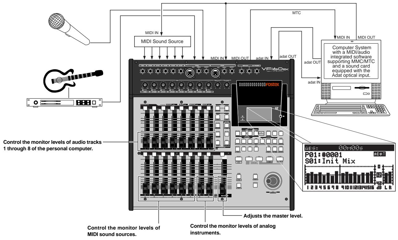
Setup of the VF160EX
- Set both "digital input" and "digital output" settings in the Setup mode to "adat".
See pages "141" and "142" for details about settings.
- When the Normal display is shown, press the [INPUT SEL] key while holding down the [SHIFT] key to make the "Adat Mixer Mode" active.
Connection to external equipment
-
Connect the VF160EX [DATA IN] and [DATA OUT] connectors respectively to the adat IN and adat OUT connectors of the personal computer containing a sound card.
-
Connect the MIDI OUT connectors of the personal computer to the MIDI IN connectors of the MIDI sound source device and the VF160EX, and connect MIDI sound sources to the VF160EX inputs 1 through 6.
- Connect analog sound sources (such as mic, guitar, etc.) to inputs 7 and 8.
- Connect the VF160EX [MIDI OUT] connector to the [MIDI IN] connector of the personal computer, and feed MTC from the VF160EX to the computer.
Chain play function
The chain play function allows you to play back programs in order according to the "chain play list". As examples in figure 1, you can play back programs in order of program number or in desired order.
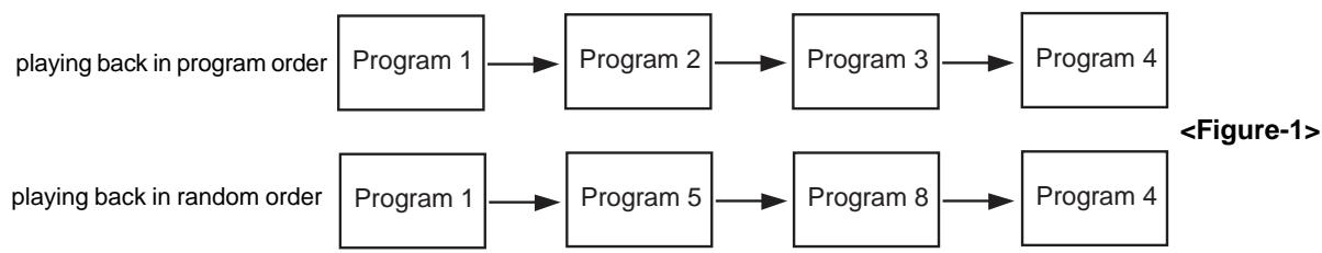
You can play the whole (i.e. from ABS 0 to REC END) of each program in the chain play list as shown in figure 2, as well as a desired part(*) of each program as shown in figure 3.
(*) A desired part can be specified as a range between the Auto Return Start and Auto Return End points. Therefore, if a program does not have both the Auto Return Start and End points which are correctly set, the whole program (from ABS 0 to REC END) is played back.
See page 35 of the owner's manual for details about how to set the Auto Return Start and End points.
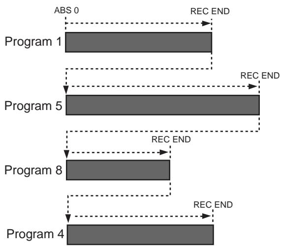
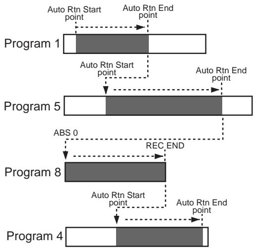
In addition, you can select a playback mode for the chain play function from among "Pause", "A. Play" and "Repeat" (see below for details about each mode).
| Pause | In this mode, the VF160EX plays back each program in the chain play list one by one.
Each time the VF160EX finishes playback of a program, it automatically pauses at the start point of the next program. Pressing the [PLAY] key starts playback. |
| A. Play | In this mode, the VF160EX plays back all programs in the chain play list continuously.
After finishing playback of the last program, the VF160EX pauses at the start point of the first program.
Pressing the [PLAY] key again starts playback of all programs in the chain play list continuously. |
| Repeat | In this mode, the VF160EX plays back all programs in the chain play list continuously and repeatedly until you press the [STOP] key. |
Making the chain play list
Before executing chain play, you must make the chain play list by selecting the desired (or all) programs in the desired order. You can enter up to 99 programs to the chain play list.
On pages 98 and 99, two procedure examples for entering programs on the VF160EX current drive to the list are shown. The former example shows how to enter all programs on the current drive, while the latter shows how to enter desired programs. Both examples assume that 10 programs exist on the current drive.
1. While the VF160EX is stopped, press the [SETUP] key.
The VF160EX enters the setup mode and the display changes to show the "Select Menu" screen for selecting a setup menu item. By default, the "Signature Set" flashes as shown in the figure below.
![FOSTEX VF160EX - While the VF160EX is stopped, press the [SETUP] key. - 1](/content/2025/01/168450/images/e691ad0930a4154f278c4427c59ef667d988bd8422b0ec1f25406611f3e4676e.jpg)
2. Use the [JOG] dial to select "Chain Play List" which is the 23rd menu item (R23) in the setup menu, and then press the [ENTER/YES] key.
The display changes to show the "Chain Play List" screen, in which "C01:END" is highlighted by default. "C01" shows the step number, while "END" shows no program is entered to the chain play list.
![FOSTEX VF160EX - Use the [JOG] dial to select "Chain Play List" which is the 23rd menu item (R23) in the setup menu, and then press the [ENTER/YES] key. - 1](/content/2025/01/168450/images/f15665656e81f9b0586bdc0a76e21048fab1f5c69e78833be0c270f2fd30aee4.jpg)
3. Press the [ENTER/YES] key again.
"END" starts flashing and you can now enter a desired program to step 01.
![FOSTEX VF160EX - Press the [ENTER/YES] key again. - 1](/content/2025/01/168450/images/fdc72318cd310ff079f0813575aae3d1978759ee9739efa7004ec81989be7bb5.jpg)
By rotating the [JOG] dial while "END" is flashing, you can select a desired option from among the programs on the drive ("P01" through "P10"), as well as "ALL", "INS" and "DEL". See the table below for details about each option.
| END | The current and succeeding steps in the chain play list are all deleted. (See “Deleting all programs from the chain play list” described later for details.) |
| ALL | All programs on the current drive are entered to the chain play list. Note that you can select “ALL” to step 1 (C01) only. There is no “ALL” option on other steps. (See “Making the chain play list by selecting all the programs” described later for details.) |
| INS | A desired program can be added (inserted) to the current step. (See “Inserting a program to the chain play list” described later for details.) |
| DEL | The program on the current step is deleted. (See “Deleting a program from the chain play list” described later for details.) |
| P01 ~ Pnn | A desired program is entered to the current step. If another program is already entered, the new program overwrites it. You can select any of the programs on the current drive. (See “Making the chain play list by selecting desired programs” described later for details.) |
Making the chain play list by selecting all the programs
The following procedure example shows how to enter all the programs (P01 through P10) on the current drive to the chain play list.
1. While "END" is flashing, rotate the [JOG] dial to select "ALL", and press the [ENTER/YES] key.
By rotating the [JOG] dial to the left, you can find "ALL" easily.
By pressing the [ENTER/YES] key after selecting "ALL", all programs on the current drive are entered to the chain play list, as shown in the screen example below.
![FOSTEX VF160EX - While "END" is flashing, rotate the [JOG] dial to select "ALL", and press the [ENTER/YES] key. - 1](/content/2025/01/168450/images/99b37f224e9d5adb7dc323d02b08562318aeae1f48423df4f0e6786b565f776c.jpg)
By rotating the [JOG] dial, you can scroll through the list to check the chain play list. In the last line on the list, "C11: END" is shown, which shows that no more program is entered after step 11.
2. Press the [EXIT/NO] key.
The chain play list is made and the "Chain Play List" screen is dismissed. The display returns to the "Select Menu" screen, where the current option of the "Chain Play" menu item flashes (by default, "Off" flashes) and you can now set the chain play mode.
![FOSTEX VF160EX - Press the [EXIT/NO] key. - 1](/content/2025/01/168450/images/a16c8bae486e969a83a80d5381d55691fe0be89c51508a8bfd0602ae7aaa0561.jpg)
For details about how to set the chain play mode, see "Setting the chain play mode" on page 99.
If a program which participates in the chain play list is deleted from the drive(see "Deleting a program" in the owner's manual), the whole play list is cleared (it returns to show "CO1: END").
If you select the "Delete" menu item of the Setup mode and press the [ENTER/YES] key, the display shows the warning message ("[WARNING] Delete Play List too?").
Making the chain play list by selecting desired programs
The following procedure example shows how to enter the five desired programs (from among 10 programs on the current drive) to steps 1 through 5 in the chain play list, as below.
: C01 -> program 5 (P05)
: C02 -> program 3 (P03)
: C03 -> program 1 (P01)
: C04 -> program 2 (P02)
: C05 -> program 4 (P04)
1. While "END" is flashing on the screen, rotate the [JOG] dial to select "P05" and press the [ENTER/YES] key.
You can select the desired program by rotating the [JOG] dial to the right.
When selecting the program, the first nine characters of the program name is also shown (in the example below, the name is "#0005").
After selecting "P05" and pressing the [ENTER/YES] key, program 5 (P05) is set to step 1 (C01) of the chain play list and the screen changes as shown below.
![FOSTEX VF160EX - While "END" is flashing on the screen, rotate the [JOG] dial to select "P05" and press the [ENTER/YES] key. - 1](/content/2025/01/168450/images/5c138a9ff9c93a256033ccfebf76be95901827fbb1b6df23e6c3e38a33cab56c.jpg)
2. Use the [JOG] dial to highlight "C02: END" and press the [ENTER/YES] key.
As with procedure step 1) above, "END" of "C02: END" starts flashing.
![FOSTEX VF160EX - Use the [JOG] dial to highlight "C02: END" and press the [ENTER/YES] key. - 1](/content/2025/01/168450/images/f3770882bb85e835346b82d4f9688b4b7c0479b57b058fe743d2831a636d3ea6.jpg)
3. While "END" is flashing on the screen, rotate the [JOG] dial to select "P03" and press the [ENTER/YES] key.
As with procedure step 1) above, program 3 (P03) is set to step 2 (C02) of the chain play list and the screen changes as shown below.
![FOSTEX VF160EX - While "END" is flashing on the screen, rotate the [JOG] dial to select "P03" and press the [ENTER/YES] key. - 1](/content/2025/01/168450/images/cbdb59cfd4137ef7022dfabe5882874c4d320b5f3a354f9df7f5c642d8ab0a36.jpg)
Set programs to steps 3 through 5 (C03 through C05) of the chain play list with the same manner as above.
4. After completing setting all the desired programs to the chain play list, press the [EXIT/NO] key.
The chain play list is made and the "Chain Play List" screen is dismissed.
The display returns to the "Select Menu" screen, where the current option of the "Chain Play" menu item flashes (by default, "Off" flashes) and you can now set the chain play mode.
For details about how to set the chain play mode, see "Setting the chain play mode" on page 99.
Setting the chain play mode
When you have made the chain play list, set the chain play mode. The following procedure shows how to set the chain play mode after making the chain play list as described before.
1. While "OFF" which is the current option of the "Chain Play" mode setting is flashing on the screen, rotate the [JOG] dial to select a desired chain play mode option.
You can select a chain play mode option from among "Pause", "A. Play" and "Repeat", besides "Off".
![FOSTEX VF160EX - While "OFF" which is the current option of the "Chain Play" mode setting is flashing on the screen, rotate the [JOG] dial to select a desired chain play mode option. - 1](/content/2025/01/168450/images/564ada5a2c71a7a21bc2cd1b9daf41fdc0be39533d3fc79f8743662f057334e5.jpg)
- The chain play mode setting returns to the default setting ("Off") when turning off the power or executing play list editing (described later). Therefore, each time you want to carry out chain play after turning on the power or executing play list editing, you must set the chain play mode.
- If you are going to set the chain play mode while the chain play list has not been made, "[WARNING] Illegal Play List!" is shown and the setting is invalid.
2. After selecting the desired option, press the [ENTER/ YES] key.
The VF160EX enters the selected play mode, while the Setup mode exits. The display shows the beginning (ABS 0, or the Auto Return Start point) of the program set to step 1 in the play list. In this condition, pressing the [PLAY] key starts playback of the play list by the selected play mode (if the play mode is set to "A. Play" or "Repeat", playback starts automatically).
The current play mode is shown for a few seconds after starting playback, as shown in the example below (in this example, the play mode is set to Auto Play).
The normal screen example when setting the play mode
The example of the play mode display
![FOSTEX VF160EX - After selecting the desired option, press the [ENTER/ YES] key. - 1](/content/2025/01/168450/images/90b3e714ecd90c2a257d5dcd08f5f431a16f4bb7d8799c919e6cfa6363229eab.jpg)
- When the chain play mode is set to any option but "Off", you cannot make the auto punch mode or auto function mode active. If you are going to make either of them active, "[WARNING] Void! Chain Play" is shown and the operation is invalid.
- When setting the chain play mode to "Repeat" and exiting the setup mode, the recorder automatically starts playback from the start point (the ABS 0 or Auto Return Start point) of the first program in the chain list. (When setting the chain play mode to "Pause" or "A. Play" and exiting the setup mode, the recorder moves to the beginning of the first program in the chain list.
- When the chain play mode is set to any option but "Off", you can change the current program (by [PGM SEL] key) only from among the programs set to the chain play list (see "Selecting a program from the chain play list" on page 100).
When the play mode is set to any option but "Off", the recorder immediately locates to the start point of the program set to step 1 (C01) in the play list, and then stops.
If you move the recorder to a position out of the range between the Auto Return Start and End points (or after the REC END point), "Out of Zone" is shown instead of the step number. In such a condition, the recorder does not correctly execute chain play. The worst case is that you start chain play when the recorder position is after the Auto Return End point (or the REC END point). The recorder never moves to the next program.
To move the recorder to the start point of a program, reselect a program you want to start chain play from by following the procedure described below.
Selecting a program in the chain play list
If the play mode is set to any option but "Off", you can select a program only from those set to the chain play list. By selecting a program, you can start chain play from the desired step in the chain play list.
If you want to select any program on the disk, as usual, turn off the power and then on, or set the chain play mode to "Off" (see "Setting the chain play mode").
In the following procedure, it is assumed that the chain play list has been made, the play mode is set to an option but "Off", and the program set to the first step of the chain play list is loaded.
- While the recorder is stopped, press the [PGM SEL] key. After showing "Select Change No!" immediately, the display changes to show the screen as below, on which the current program list number and "Sure?" flash. In this condition, you can select another program set in the list by rotating the [JOG] dial.
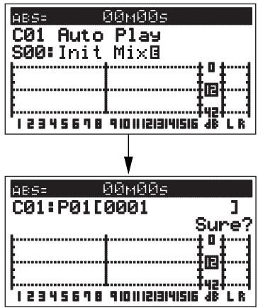
- Use the [JOG] dial to select the desired step and press the [ENTER/YES] key.
The program set to the selected step is loaded and the recorder is stopped at the beginning of the program (ABS 0), while the display shows the Normal screen. In the screen examples below, program 4 (P04) set to step 4 (C04) is selected.
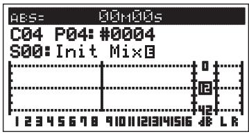
As described above, by selecting a program while the chain play mode is set to any option but "Off", you can start chain play from the desired program.
Editing the chain play list
You can replace a program in the chain play list with another program, delete a program from the list, or add a new program to the list.
- Deleting (or replacing) a program in the chain play list
You can delete a desired program from the chain play list or replace a program in the list with another program by following the procedure below.
- While the recorder is stopped, press the [SETUP] key to enter the setup mode.
The screen for selecting a menu item in the setup mode appears.
- Use the [JOG] dial to select "Chain Play List", and press the [ENTER/YES] key.
The display changes to show the "Chain Play List" screen as below.
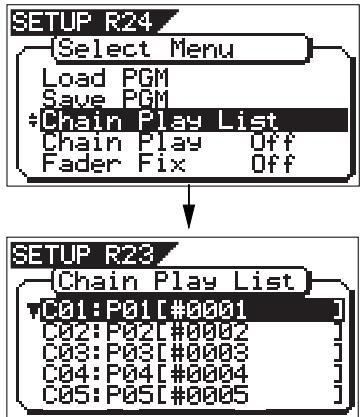
- Use the [JOG] dial to select the step you want to edit, and press the [ENTER/YES] key.
The program number set to the selected step starts flashing. In the example below, "P03" which is set to step 3 (C03) is flashing.
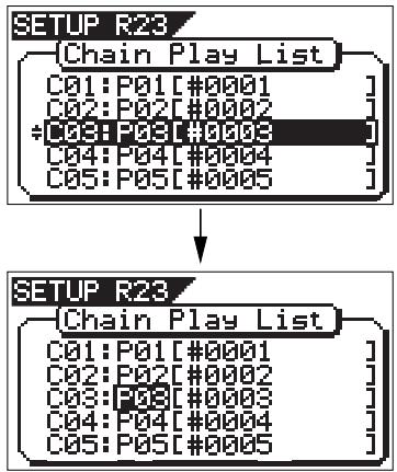
- Use the [JOG] dial to select "DEL" (or a desired program) and press the [ENTER/YES] key.
To delete the program from the chain play list, select "DEL". To replace the program with another program, select a desired program.
If you delete the program from the list, all the programs set to the subsequent steps automatically slide up, as shown below.
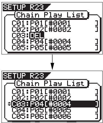
If you select a desired program, the program set to the selected step is replaced and other steps are not affected (in the following example, "P03" set to "C03" is replaced with "P08").
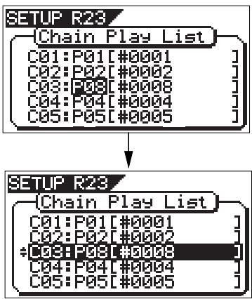
To delete (or replace) another program, repeat the procedure shown above.
5. Press the [EXIT/NO] key to exit the "Chain Play List" screen.
The display returns to the "Select Menu" screen where the current option of the "Chain Play" mode setting is flashing.
If you delete or replace a program in the chain play list when "Chain Play" is set to any option but "Off", the "Chain Play" setting automatically changes to "Off" (which is the default). Therefore, to execute chain play after editing the chain play list, you must make the "Chain Play" mode setting appropriately again.
Deleting all programs from the chain play list
You can delete all the program in the chain play list simultaneously.
1. Follow procedure steps 1) and 2) on page 100 to show the "Chain Play List" screen.
(i.e. enter the setup mode and select "Chain Play List".)
2. While step 1 (C01) is highlighted (selected), press the [ENTER/YES] key.
The program number set to step 1 (P01) starts flashing. If step 1 ("C01") is not highlighted, use the [JOG] dial to select step 1 and press the [ENTER/YES] key.
![FOSTEX VF160EX - While step 1 (C01) is highlighted (selected), press the [ENTER/YES] key. - 1](/content/2025/01/168450/images/b78f6fd96a46195f6a09851eb2ae3f5d5a7b3484788127ee6c713a9341f0cea9.jpg)
3. Use the [JOG] dial to select "END" and press the [ENTER/YES] key.
All the programs in the list are deleted at once and the screen shows as below ("C01: END" is shown in the chain play list, which means no program is entered to the list).
![FOSTEX VF160EX - Use the [JOG] dial to select "END" and press the [ENTER/YES] key. - 1](/content/2025/01/168450/images/f8177e975e8c1a62d599096991ab7a2596d93fd96df7ee589517ab940eed845f.jpg)
If you select any step but "C01" in procedure step 2) above and follow procedure step 3), programs set to the selected and subsequent steps are deleted from the list. For example, if you set "END" to step 3 (C03) in the chain play list where ten steps are currently set, programs set to steps 3 through 10 are all deleted, while programs set to steps 1 and 2 remain.
4. Press the [EXIT/NO] key repeatedly until the setup mode exits.
The "Chain Play" mode setting is automatically changed to "Off".
Inserting a program to the chain play list
You can insert a program to a desired step in the current chain play list.
- Follow procedure steps 1) and 2) on page 100 to show the "Chain Play List" screen.
(i.e. enter the setup mode and select "Chain Play List".)
- Use the [JOG] dial to select a step where you want to add a program and press the [ENTER/YES] key.
The program number set to the selected step starts flashing. If you select "C02" on the left screen example below, "P02" starts flashing.
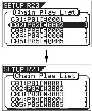
- Use the [JOG] dial to select "INS" and press the [ENTER/YES] key.
You can now select a program to be inserted. Initially, "P01" flashes. As you can see by comparing the two screen examples above, the programs set to the second and subsequent steps slide down automatically.
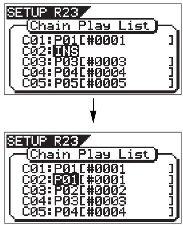
- Use the [JOG] dial to select a program to be inserted, and press the [ENTER/YES] key.
In the example shown below, program 6 (P06) is inserted to step 2.
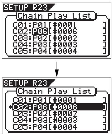
If you want to insert a program to another step, repeat the same procedure above.
You can enter up to 99 programs to the play list. If you are trying to enter a program to the play list where 99 programs are already registered, "Void! Play List is Full" is shown and the operation is canceled.
- After inserting all desired programs, press the [EXIT/NO] key.
The "Chain Play List" screen is dismissed and the display returns to the "Select Menu" screen where the current option of the "Chain Play" mode setting is flashing.
If you insert the desired program(s) to the chain play list when the "Chain Play" mode is set to any option but "Off", the "Chain Play" setting automatically changes to "Off" (the default). Therefore, to execute chain play after editing the chain play list, you must set the "Chain Play" mode appropriately again.
- After setting the "Chain Play" mode appropriately, press the [EXIT/NO] key repeatedly until exiting the setup mode.
Audio CD playback mode
This mode allows playing back an audio CD (regardless of whether it is made using the VF160EX or on the market) using the CD-R/RW drive (model CD-1A/EX).
By switching the HDD playback mode to the audio CD playback mode, you can operate the CD-R/RW drive from the transport keys ([PLAY], etc) on the VF160EX panel for monitoring an audio CD.
- You cannot play back an audio CD which is copy-protected.
- Never try to play back a disc which is not an audio CD (CD-DA). This may damage the VF160EX.
- In the audio CD playback mode, you can use functions such as locate, scrub, auto function and effect editing, as with internal HDD playback. However, note that the access speed is not guaranteed.
Switching the playback mode
When turning the power on, the VF160EX always starts up in the internal HDD playback mode. In the following description, it is assumed that the CD-R/RW drive is installed to the VF160EX and an audio CD (burned using the VF160EX or on the market) is inserted to the drive.
- When the HDD is stopped, press the [SCRUB/CD PLAY] key while holding down the [SHIFT] key.
After the associated warning message as shown below appears, the playback mode changes. Executing the above operation alternatively switches the playback mode.
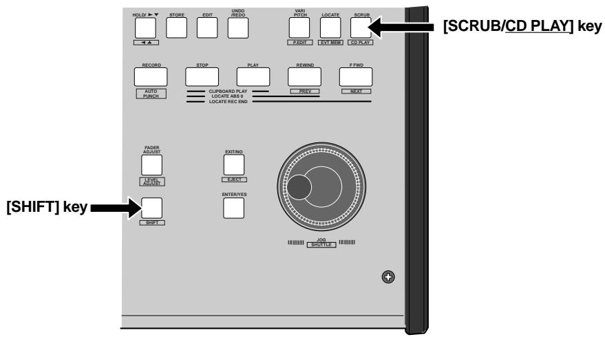
the HDD playback mode to the audio CD playback mode
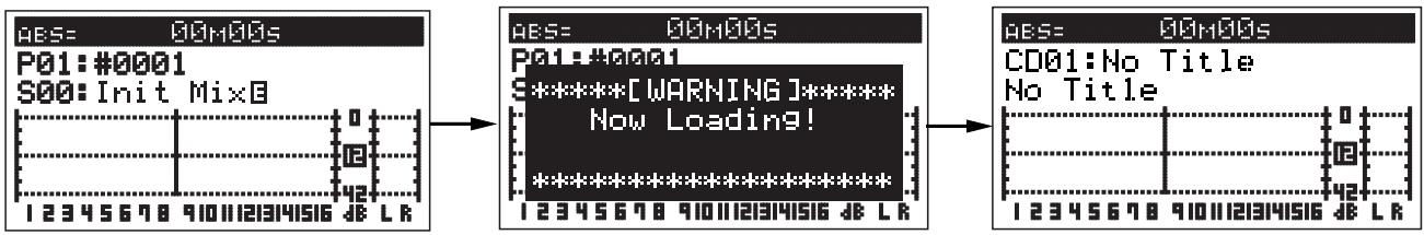
the audio CD playback mode to the HDD playback mode
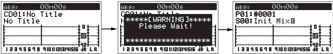
When switching the playback mode, make sure that the VF160EX is not accessing the CD-R/RW disc.
Available functions in the audio CD playback mode
In the audio CD playback mode, only the [CH STATUS/ CH SEL] keys for tracks 1, 2 and [MASTER] are lit, while the other [CH STATUS/CH SEL] keys are unlit, showing that only the faders for track 1, 2 and [MASTER] are effective. (This means that the playback level of the audio CD is adjusted using the faders for tracks 1, 2 and [MASTER].)
In the audio CD playback mode, the following functions are available.
If you are going to carry out any function other than the following, a warning message is shown and the operation is ignored (for example, if you press the [RECORD] key while holding down the [SHIFT] key, "[WARNING!] Void Key CD PLAYER" is shown.
- Normal playback
You can play back an audio CD with the same manner as with a program in the internal HDD. You can control the playback level using the faders for tracks 1, 2 and [MASTER].
If you press the [PLAY] key, the key indicator flashes for a while. This shows that the system is in preparation for audio CD playback. When it is ready, playback starts.
Track skip
If an audio CD contains more than one track, pressing [REWIND/PREV] or [F FWD/NEXT] key while holding down the [SHIFT] key skips a track. By pressing the key, "Locate: EVT **" ( ^ shows the event number) is shown on the display, and the playback position skips (locates) to the beginning of the appropriate track.
- Auto functions
When the Start and End points are correctly set, the auto functions (Auto play, Auto return, Auto repeat, etc.) are available.
- See page 69 of the owner's manual for details about the auto functions.
- Varipitch playback
You can use the varipitch playback function which allows to alter the playback speed within + / - 6.0% range in 0.1% increments/decrements.
- For details about the varipitch function, see page 68 in the owner's manual.
- Effect, EQ and pan controls
You can use the effect, EQ and pan controls for tailoring the playback sound.
- For details about the effect function, see pages 41 and 52 in the owner's manual.
- For details about the EQ function, see pages 40 and 51 in the owner's manual.
- For details about the pan control, see pages 40 and 50 in the owner's manual.
- Ejecting an audio CD
In the audio CD playback mode and when the VF160EX is not accessing the disc, you can eject a disc in the CD-R/RW drive by pressing the [EXIT/NO] key while holding down the [SHIFT] key, or pressing the eject key on the CD-R/RW drive.
- Display time mode selection
By pressing the [DISP SEL] key, you can select the time mode on the display from among "ABS", "Offset" and "MTC". For details about the time mode selection In the internal HDD playback mode, see page 30 of the owner's manual.
- See the next page for details about the time display.
Display in the audio CD playback mode
When switching to the audio CD playback mode, the display looks like the example below.
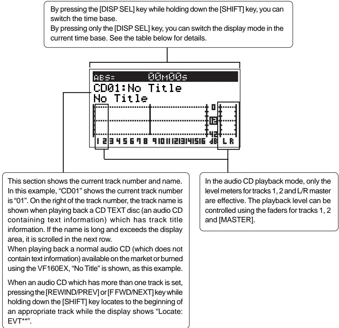
- Time base display mode selection by the [SHIFT] key and [DISP SEL] key
| ABS | Disc elapsed time is shown. The time starts from the beginning of a disc. The loop start and end points refers to disc elapsed time. |
| OFFSET | Track elapsed time is shown. Track time starts from the beginning of each track. Naturally, at the point each track starts playback, the display shows “00m00s”. |
| MTC | MTC (MIDI Time Code) is shown. It has an offset of 59 minutes 57 seconds to “ABS 0” (the same offset as the internal HDD playback mode). |
- Display mode selection in the current time base by the [DISP SEL] key
| When the current time base is ABS: | You can switch between “ABS”, “OFFSET” and “MTC IN”. |
| When the current time base is OFFSET: | You can switch between “OFFSET” and “MTC IN”. |
| When the current time base is MTC: | You can switch between “MTC”, “OFFSET” and “MTC IN”. |
MTC IN: Show the MTC time input in the [MIDI IN] jack.
Chapter 6 Save/Load of song data
You can save or load the desired song data using an S/PDIF digital signal, adat digital signal, as well as the CD-R/RW drive (Model CD-1A/EX). The file formats you can use are the FDMS-3 (Fostex Digital Management System-3) and WAV. This function allows you to save finished or unfinished song data, including audio data and various SETUP information, to an external digital recorder or CD-R/RW drive, and load the data later. You can also make an original audio CD (CD-DA) using a CD-RW/CD-R disc.
******About song data*****
The format and time required for the save/load operations are different between each method.
- Using the S/PDIF digital signal (you can save/load data for each program individually.).
Five seconds after the pilot signal (shown in gray in the diagram below), the song data is output to an external DAT recorder. The audio data is divided into data blocks of track pairs (shown in black in the diagram below) and transferred. To save data for all Real and Additional tracks (totally 24 tracks), 12 two-track units of data are transferred. Therefore, it will take about 12 times as much as the recorded time of a program (from ABS 0 to REC END) to save all the data recorded on the program.
When loading song data from a DAT to the VF160EX, data is transferred with two-track data blocks, the same as saving data. (See also on the next page.)
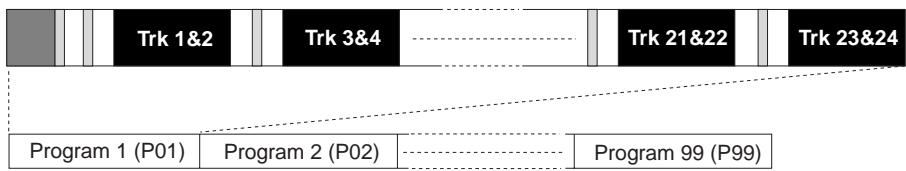
- Using the adat digital signal (you can save/load data for each program individually.):
Five seconds after the pilot signal (shown in gray in the diagram below), the song data is output to an external adat recorder. The audio data is divided into data blocks of 8 tracks (shown in black in the diagram below) and transferred. To save data for all Real and Additional tracks (totally 24 tracks), 3 units of eight-track data are transferred.
Therefore, it will take about 3 times as much as the recorded time of a program (from ABS 0 to REC END) to save all the data recorded on the program.
When loading song data from an adat recorder to the VF160EX, data is transferred with eight-track data blocks, the same as saving data. (See also on the next page.)
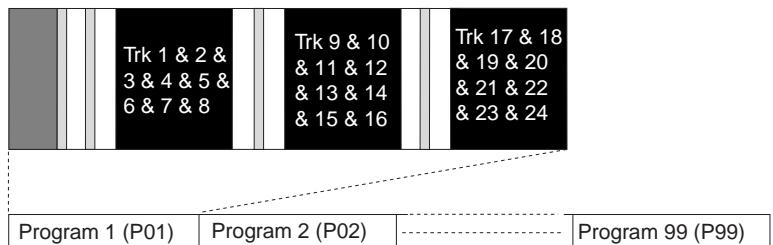
- Using a CD-RW/CD-R disc (you can save/load data for each program individually.):
When using a CD-RW/CD-R disc, all audio data including both the Real and Additional tracks (shown in black in the diagram below) is transferred simultaneously. No pilot tone or beep sound is recorded when saving data to a CD-RW/CD-R disc. Therefore, you can save or load a program much faster than using an S/PDIF or adat signal.
If song data to be saved requires more space than the available disc space, you can save the data to more than one disc (up to 99 discs). In a save/load operation using a WAV file, you can specify a track or tracks to be saved or loaded, as well as all tracks. Using the save function to a CD-RW/CD-R disc, you can also make an original audio CD.
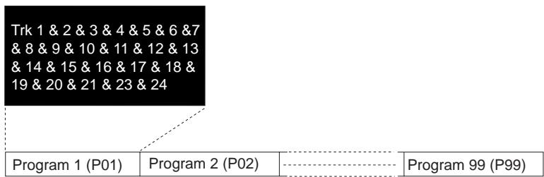
Memory data:
Data for CLIPBOARD IN/OUT, AUTO RTN START/END, AUTO PUNCH IN/OUT.
Locate data (for Locate No. 00 through 99, only available with save/load using CD-RW/CD-R)
Time base:
ABS, MTC or BAR/BEAT/CLK
-SETUP mode:
Bar/beat setting, tempo setting, metronome on/off, preroll time, MIDI synchronization output signal setting, MTC offset time, MTC offset mode, REC protect setting, slave mode on/off, slave type setting
- On/off settings for Auto play mode and Auto return mode
- Vari pitch on/off and pitch data
-SETUP mode:
DIGITAL IN and DIGITAL OUT settings, bar/beat resolution on/off and device ID
Save/load of song data using the S/P DIF or adat digital signal
The VF160EX song data only can be saved to or loaded from a digital machine that can record 16 bit, 44.1 kHz linear digital data with S/PDIF or adat format (such as DAT and adat machines).
When saving all data including both real and Additional track data using the S/PDIF or adat digital signal, note the following.
Only the data recorded within the time duration between ABS 0 and REC END of the Real tracks is saved. Therefore, if the recorded time of Additional tracks is longer than the Real tracks, only the Additional track data within the time duration between ABS 0 and REC END of the Real tracks is saved.
In the example shown on the right, the Additional tracks have data from "00m 00s" to "10m 00s", while the Real tracks have data from "00m 00s" to "07m 00s".
If you are going to save all tracks, the Additional track data from "00m 00s" to "07m 00s" will be saved but the rest will not be saved.
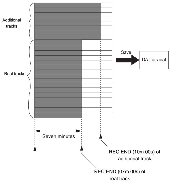
Saving data using the S/P DIF or adat digital signal
You can save data using the S/PDIF or adat digital signal via the [DIGITAL/DATA OUT] jack.
*Use an external device that supports 44.1 kHz sampling frequency (the same as the VF160EX).
Connecting to an external device
Connect the DIGITAL/DATA OUT jack to the digital input jack of the external digital device (DAT or adat etc.).
The DIGITAL/DATA OUT jack accommodates either the S/PDIF (optical) or adat digital signal selected. Though the S/PDIF (optical) and adat digital signal use the same connector shape, the signal formats are different.
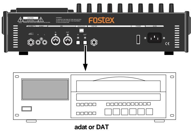
- When using the S/PDIF signal, if your DAT only provide the coaxial (RCA) digital input jack and does not provide the optical jack, use the optional COP-1/96kHz (optical/coaxial converter).
- Do not connect digital signals for both directions between the VF160EX and the external device (i.e. the digital output of the VF160EX to the digital input of the external device and the digital output of the external device to the digital input of the VF160EX), which may form a digital loop and cause feedback.
Setting the external device
- Set the sampling frequency to 44.1 kHz (the same as the VF160EX).
- Set the input source to "digital input" to accept the signal from the VF160EX.
Some machine also needs to select the clock reference to "external" when setting the input source to "digital input". See the operation manual of the machine for the detailed information.
If you cannot hear the input signal or you hear digital noise when monitoring the source signal of the external digital device, check the connections, cables and settings of both the VF160EX and the external device.
*See the operation manual of the external device for the detailed information.
Saving data
You can save data via the "Save PGM" menu in the SETUP mode.
- Output signal options: OPT (adat or S/PDIF) IDE (CD-1A/EX)
-Program options: P01 to P99 (an individual Program)
Track options:
- When using S/PDIF or adat:
Tracks 1-8, Tracks 1-16, Tracks 1-24, Tracks 9-16, Tracks 9-24 or Tracks 17-24.
- When using a CD-RW/CD-R disk:
All tracks (1-24) is selected automatically. (You can select tracks individually when saving by the WAV file format).
1. Press the [SETUP] key to enter the Setup mode.
The display shows the screen for selecting the Setup menu.
- Use the [JOG] dial to select "Save PGM" and press the [ENTER/YES] key.
The display shows the screen for selecting the device to which the data is saved. "IDE" flashes.
![FOSTEX VF160EX - Press the [SETUP] key to enter the Setup mode. - 1](/content/2025/01/168450/images/836229176fb0bbef5f52bc4cf17f8987f16a5258202ebe24ed4d1467a82a5821.jpg)
- Use the [REWIND] key to select "OPT" and press the [ENTER/YES] key.
The display shows the screen for selecting "SPDIF" or "adat", in which "SPDIF" flashes.
![FOSTEX VF160EX - Press the [SETUP] key to enter the Setup mode. - 2](/content/2025/01/168450/images/0f58ca094b3095e7252c32914f0df4a15499e3cdc6e41a035ff983c39bba0a26.jpg)
If you save data using the adat digital signal, select "adat". If you save data using the S/PDIF digital signal, select "SPDIF".
4. Use the [REWIND] or [F FWD] key to select "SPDIF" (or "adat") and press the [ENTER/YES] key.
The display shows the screen for selecting the program to be saved. The program number currently selected flashes, while the data size of the program is shown. While a program number is flashing, you can select the desired program to be saved.
![FOSTEX VF160EX - Use the [REWIND] or [F FWD] key to select "SPDIF" (or "adat") and press the [ENTER/YES] key. - 1](/content/2025/01/168450/images/eb7a228738c29f5e8e48062799d6b0dda06f659c2bcdd561a58d38979c93cb83.jpg)
5. Use the [JOG] dial to select the program to be saved and press the [ENTER/YES] key.
The display shows the "Save Length" screen.
Initially, the recorded time length of the selected program (ABS 0 to REC END) is shown as the time length of data saving. Normally you do not need to edit the length but you may edit it to the desired value if needed.
![FOSTEX VF160EX - Use the [JOG] dial to select the program to be saved and press the [ENTER/YES] key. - 1](/content/2025/01/168450/images/1720d10cb31505abf5908e890f1d92f09e8461b30eed4add3b4e10ce317c3705.jpg)
For example, if the actual recorded time is 9 min. 00 sec., you can make the length of the data to be saved shorter or longer than 9 min. 00 sec., as long as the length does not exceed 59 min.59 sec.
The initially displayed value here is the length of the Real track, therefore, as noted earlier, you may edit the value to match the length of the Additional track if it is longer.
To edit the save length
Press the [REWIND] or [F FWD] key to move the flashing field between "minutes" and "seconds".
Use the [JOG] dial to set the value for the flashing field.
6. Press the [ENTER/YES] key.
The display shows the screen for selecting tracks to be saved.
![FOSTEX VF160EX - Press the [ENTER/YES] key. - 1](/content/2025/01/168450/images/193f30cd1d1a44eb0a42b39398cdc89e387205524e9e55943f45d31f99f059f4.jpg)
7. Select tracks to be saved.
Press the [REWIND] or [F FWD] key to move the flashing field between "From" and "To".
Use the [JOG] dial to set the track number for the flashing field. For the "From" field, you can select from 1, 9 and 17. For the "To" field, you can select from 8, 16 and 24. For example, if you select "From 1 to 24", data for all tracks (1 to 24) will be saved.
When you save tracks including Additional tracks, read on page 107 before executing the save operation.
8. After selecting tracks, press the [ENTER/YES] key again.
The display shows "Rec Start Recorder!" together with the program and tracks to be saved, and "Sure?" flashes.
This means "are you sure to start saving data to recorder?"
![FOSTEX VF160EX - After selecting tracks, press the [ENTER/YES] key again. - 1](/content/2025/01/168450/images/e21e1bca92ecd70088fc008bb29e8afda2074c382a9c2ef6a9a0bfb273b2b8f3.jpg)
9. After checking any preparations on the external digital recorder are made, start it recording.
It may be a good idea to put a START-ID (for DAT) or set a locate memory at the starting position so that you can easily find the position when you load the data later.
10. Press the [ENTER/YES] key right after the external machine starts recording.
The display shows something like the one below. After a few seconds, the unit starts saving the data and "Wait time" starts counting down.
![FOSTEX VF160EX - Press the [ENTER/YES] key right after the external machine starts recording. - 1](/content/2025/01/168450/images/9eeccce53a50e13eec40c0362ce6cd66fbd3fed9fae2af72a47b902210197299.jpg)
For the first several seconds, the VF160EX transmits the pilot signal that will a reference for locating the tape position during the load operation, and the actual data saving starts from the position at which "Wait time" starts counting down.
Using the "S/PDIF" signal, data is saved in 2-track unit. Using the "adat" signal, data is saved in 8-track unit. When the data saving is completed, "Completed!" appears on the screen and the VF160EX stops.
If you interrupts saving before completing, the saved data is invalid.
11. Stop the external recorder machine.
12. Press the [EXIT/NO] key (or the [STOP] key) repeatedly until exiting the Setup mode.
To cancel each operation or to return to the previous screen before pressing the [ENTER/YES] key, press the [EXIT/NO] key (or the [STOP] key). Each press of the key returns to the previous screen and finally exits the Setup mode.
Loading data using the S/P DIF or adat digital signal
You can load data using the S/PDIF or adat digital signal via the [DIGITAL/DATA IN] jack.
*Use an external device that supports 44.1 kHz sampling frequency (the same as the VF160EX).
Connecting to an external device
Connect the [DIGITAL/DATA IN] jack to the digital output jack of the external digital device.
- The DIGITAL/DATA OUT jack accommodates either the S/PDIF (optical) or adat digital signal selected. Though the S/PDIF (optical) and adat digital signal use the same connector shape, the signal formats are different.
- Do not do anything, such as unplug the optical cable, that interrupts the digital signal until the loading operation is completed. Otherwise, the unit may generate a noise which damages an external device.
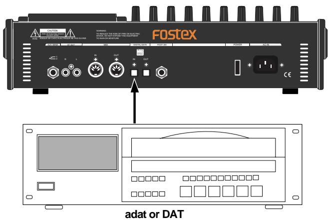
- When using the S/PDIF signal, if your DAT only provide the coaxial (RCA) digital input jack and does not provide the optical jack, use the optional COP-1/96kHz (optical/coaxial converter).
- Do not connect digital signals for both directions between the VF160EX and the external device (i.e. the digital output of the VF160EX to the digital input of the external device and the digital output of the external device to the digital input of the VF160EX), which may form a digital loop and cause feedback.
Setting the external device
- Make preparations of the external device for outputting the digital signal.
- Locate the beginning of the pilot signal for the song data.
*See the operation manual of the external device for the detailed information.
Loading data
You can load data via the "Load PGM" menu in the SETUP mode.
- Input signal options: OPT (adat or S/PDIF)
IDE (CD-1A/EX)
-Program options: P01 to P99 (an individual Program)
Track options:
- When using S/PDIF or adat:
Tracks 1-8, Tracks 1-16, Tracks 1-24, Tracks 9-16, Tracks 9-24 or Tracks 17-24.
- When using a CD-RW/CD-R disk:
All tracks (1-24) is selected automatically. (You can select tracks individually when loading a WAV file).
- Press the [SETUP] key to enter the Setup mode.
The display shows the screen for selecting the Setup menu.
- Use the [JOG] dial to select "Load PGM" and press the [ENTER/YES] key.
The display shows the screen for selecting the device from which the data is loaded. "IDE" flashes.
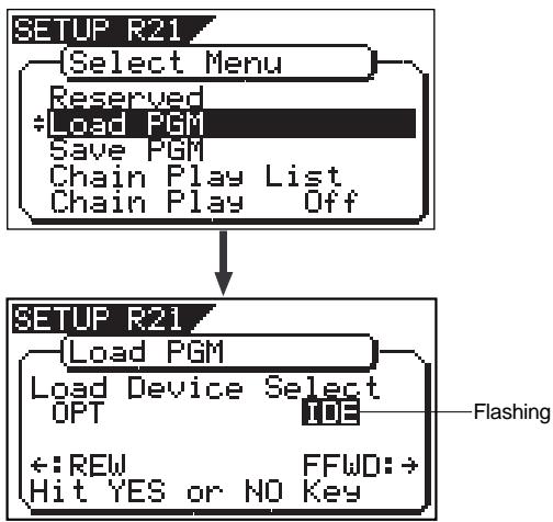
- Use the [REWIND] key to select "OPT" and press the [ENTER/YES] key.
The display shows the screen for selecting "SPDIF" or "adat", in which "SPDIF" flashes.
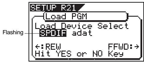
If you load data using the adat digital signal, select "adat". If you load data using the S/PDIF digital signal, select "SPDIF".
4. Use the [REWIND] or [F FWD] key to select "SPDIF" (or "adat") and press the [ENTER/YES] key.
The display shows the screen for selecting a load destination program to which data is loaded.
A program number currently selected flashes, followed by its program name. The data size of the current program is also shown. When a program number is flashing, you can select the desired load destination program.
![FOSTEX VF160EX - Use the [REWIND] or [F FWD] key to select "SPDIF" (or "adat") and press the [ENTER/YES] key. - 1](/content/2025/01/168450/images/7584fdf9dbf5d6b79050d2b42fc4482e63b4cf92f14e83ae2feed9670c4fc7eb.jpg)
You can select a load destination program from existing programs on the current drive as well as "New PGM". When selecting "New PGM", a new program is created.
- If you load data to a program in which data is already recorded, the newly loaded data overwrites the current data track by track. Consequently, on each overwritten track, the loaded data becomes valid while the current data is erased.
5. Use the [JOG] dial to select the program to which data is loaded and press the [ENTER/YES] key.
The display shows the screen for selecting tracks to be loaded.
![FOSTEX VF160EX - Use the [JOG] dial to select the program to which data is loaded and press the [ENTER/YES] key. - 1](/content/2025/01/168450/images/4a9e8c90943f9ad03b38b2090f5050fe326ba98dd2c348ceca4ae4db8858fdb1.jpg)
6. Select tracks to be loaded.
Press the [REWIND] or [F FWD] key to move the flashing field between "From" and "To".
Use the [JOG] dial to set the track number for the flashing field. For the "From" field, you can select from 1, 9 and 17. For the "To" field, you can select from 8, 16 and 24. For example, if you select "From 1 to 24", data for all tracks (1 to 24) will be loaded.
7. After selecting tracks, press the [ENTER/YES] key again.
The display shows something like the one below. A load destination program (existing or new program) to which the data is loaded and tracks to be loaded are shown, while "Sure?" flashes.
![FOSTEX VF160EX - After selecting tracks, press the [ENTER/YES] key again. - 1](/content/2025/01/168450/images/b11ca0c23934b416161b0efa95f06ebb964de5fd65ee6e31d22c886f76020f4a.jpg)
In the above step, if the VF160EX does not lock to the digital signal from the external digital device, the following warning message appears on the display. This indicates that the VF160EX does not receive a correct digital signal (S/PDIF or adat signal). So check the cable connection and the digital output settings of the external digital device.
![FOSTEX VF160EX - After selecting tracks, press the [ENTER/YES] key again. - 1](/content/2025/01/168450/images/64141dbcc444e01a697cd36157392ef6d36698e79cfaa4ff45ec49e71f741f6d.jpg)
The display shows "Play Start Player!".
![FOSTEX VF160EX - When the VF160EX is locking to the digital input signal, press the [ENTER/YES] key. - 1](/content/2025/01/168450/images/9cf607004777f870ad68ceeffba0c0404774d1ba55ab67566f0e084990edfdaa.jpg)
9. Start playback of the player.
After reading the pilot signal recorded when saving the data, the data starts loading automatically.
When starts loading, the display shows something like the one below, in which "Wait time" starts counting down.

Using the "S/PDIF" signal, data is loaded in 2-track unit. While loading, the indicators on [CH STATUS/CH SEL] keys for channels 1 and 2 flash, while the input levels are displayed by level meters 1 and 2.
Using the "adat" signal, data is loaded in 8-track unit. While loading, the indicators on [CH STATUS/CH SEL] keys for channels 1 through 8 flash, while the input levels are displayed by level meters 1 and 8.
When the data loading is completed, "Completed!" appears on the screen.
If you quit loading before completing, the loaded data is invalid.
10. Stop the external DAT (or adat) machine.
11. Press the [EXIT/NO] key (or the [STOP] key) repeatedly until exiting the Setup mode.
To cancel each operation or to return to the previous screen before pressing the [ENTER/YES] key, press the [EXIT/NO] key (or the [STOP] key). Each press of the key returns to the previous screen and finally exits the Setup mode.
Save/Load using CD-RW/CD-R
By using the built-in CD-R/RW drive (Model CD-1A/EX), you can save/load data in the FDMS-3 format or WAV file format, as well as create or load an audio CD (CD-DA).
With a CD-R/RW drive, you can use not only CD-RW discs but also CD-R discs. Note that CD-R discs has some restrictions as shown below.
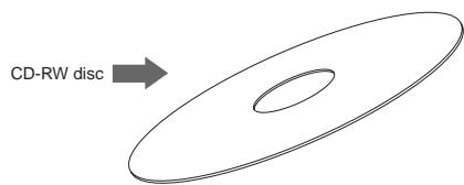

You can save (record) data to a disc as many times required. Note that when saving new data, it is recorded after the previously recorded data is erased. In other words, every time you save new data, all disc data is rewritten. (See "Saving data" described later.)

You can save (record) data to a disc only once.
You cannot save data to a recorded disc. You can, of course, load data as many times as required.
A CD-RW/CD-R disc on which VF160EX data is recorded can only be played by Fostex machines. Do not play it by non-Fostex devices. The drive or system used may be damaged.
However, a CD-R disc with audio CD format created by the Fostex machine can be played by general machines such as audio CD players. (If an audio CD is made using a CD-RW disc, it can be played back only by a player that supports CD-RW playback. You cannot playback such a disc by a conventional CD player that does not support CD-RW playback.)
The writing and reading speeds for data save and load of the VF160EX are automatically set as below.
- Writing speed: according to a CD-R/RW drive used, however the maximum speed is 8 times.
- Reading speed: according to a CD-R/RW drive used.
The writing speed depends on a CD-R/RW drive but it is limited to 8 times.
For save/load of the VF160EX data, use discs that can be written at 4 times or higher speed. Do not use discs that only can be written at real-time or twice speed.
- When handling a disc, be careful not to dirty or scratch the surface of the disc. We recommend that you hold the disc with your finger on the disc edge and center hole.
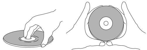
- Never use a warped or chipped disc, which may damage the CD-R/RW drive.

- Do not stick any paper, etc. on the label side. Also do not scratch the label side, which may cause problems during playback or recording. Use only a felt pen or equivalent for writing any memo on the label side. Using a ball-point pen, pencil, etc. that has a hard tip may damage a disc.
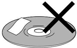
- If there is a dust, dirt or fingerprints on the disc, which may cause error in playback or recording, wipe the disc with a soft, dry cloth or alcohol from the center out. Never wipe from the outside to center.
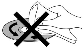
- Do not use a cleaner for analog discs or antistatic spray, as well as volatile solvents such as benzine, which may damage the disc surface.
- Do not expose any disc to direct sunlight, or leave it in hot, moist or cold places.
- Read the attached manual packed with the disc before using it.
Opening/closing the tray
- To open the tray, press the eject switch lightly.
Pressing the switch will open the tray slightly.
Then pull out the tray gently by hand to fully open it.
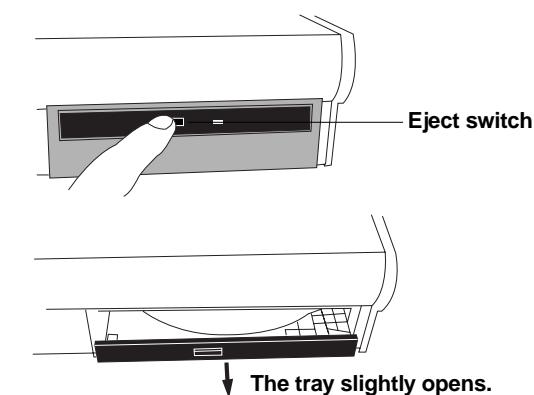
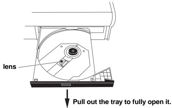
Do not touch the lens when pulling out the tray, doing so may damage it and may cause a malfunction.
- To close the tray, push the tray inside by hand until locked.

Push until it is locked.
Placing/removing a disc
The following are some notes on placing and/or removing a disc.
When placing a disc on the tray, support the tray from the bottom by your hand. If you push the disc to fit into the pivot on the tray without supporting the tray, the tray/drive may be damaged or broken. Also note that the disc must be pushed until it clicks so that it is locked into the pivot securely. Closing the tray without locking the disc may damage the disc.
When removing a disc from the tray, also support the tray from the bottom by your hand. Also be careful not to unlock the disc from the pivot forcibly, which may damage the tray.
- Place the disc with the label side up.
When placing the disc, support the tray from the bottom by your hand as shown in the illustration below, and push the disc gently until it clicks so that the disc is locked into the pivot.
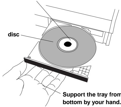
Push the disc until it clicks so that the disc is locked into the pivot.
The underside of the tray may extremely heat up.
Take care when supporting the underside of the tray.
Do not touch the lens when placing a disc, doing so may damaged may cause a malfunction.
Save/load of Song Data Using a CD-R/RW drive
When saving/loading data using the CD-R/RW drive, program data is saved/loaded as shown below.
Save
You can only a single selected program data to a disc regardless of the program data amount.
You cannot save more than one program data even if there are enough disc space.
However, you can save a program data to more than one disc if the data amount is larger than a disc space.
You can save almost all necessary information such as song data of all tracks (real and additional tracks) and mixer scene data.
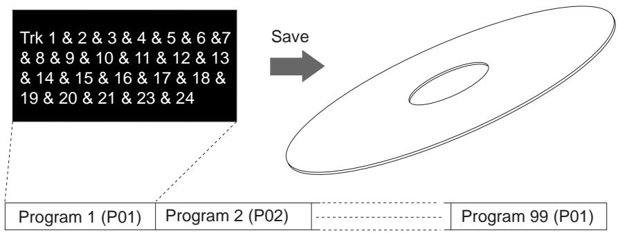
Current drive of the VF160EX
- Load
The data loading using a CD-R/RW drive is taken place after a "new program" is created in the current drive (the load destination). You cannot overwrite an existing program with the loaded data.
The newly created program is numbered the next number to the highest existing program number.
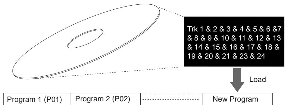
Current drive of the VF160EX
- Creating an audio CD
You can make an audio CD by recording sound data of tracks 1 and 2 between the "CLIPBOARD IN point" and "CLIPBOARD OUT point" to a CD-RW/CD-R disc.
- Loading an audio CD data
You can load a material on a (commercial or created) audio CD to a program of the VF160EX. Audio data is loaded to a "new program" automatically created by the unit, which is the same way as backup data loading. The unit never overwrites the existing program.
Saving data using a CD-R/RW drive (Backup)
The following description is assumed that a non-recorded CD-R/RW disc is used.
Do not carry out any VF160EX key operation until the access process to the CD-RW/CD-R disc is completed.
- After turning on the VF160EX, insert a disc to the CD-R/ RW drive.
- Press the [SETUP] key of the VF160EX to enter the setup mode.
The display shows the screen for selecting the setup menu.
- Use the [JOG] dial to select (highlight) "Save PGM" and press the [ENTER/YES] key.
The display shows the screen for selecting a save device, where "IDE" is flashing.
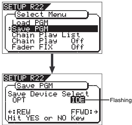
- While "IDE" flashing, press the [ENTER/YES] key.
Press the [ENTER/YES] key to display the CD-R/RW drive name, and then changes to the save mode select screen where "Bkup" (Backup) flashes.
To save (backup) song data, select "BkUp".
To make an audio CD, select "CD-DA" or "Setup".
This procedure describes how to save song data, so we select "BkUp" here.
See "making an audio CD" described later for details about how to make an audio CD.
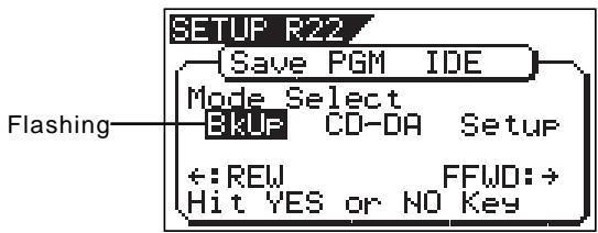
- While "BkUp" flashing, press the [ENTER/YES] key.
The display shows the screen for selecting a program to be saved (the program number of the selected program flashes).
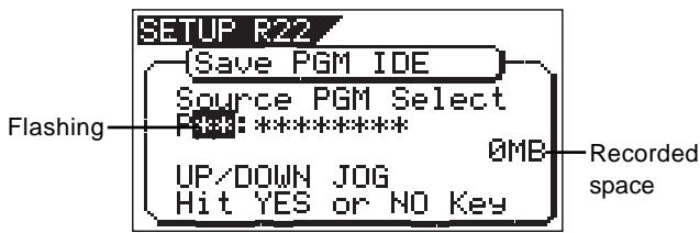
By rotating the [JOG] dial, you can select a desired program number/title from among available programs in the VF160EX current drive. The recorded space of the selected program is also shown.
If you select a program which requires more than one disc for saving, the display shows the required number of discs (see the screen example below).
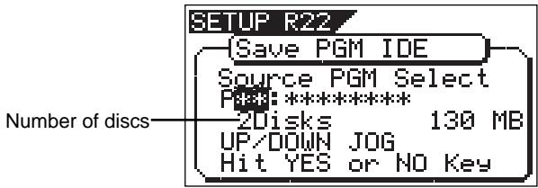
- After selecting a program, press the [ENTER/YES] key.
The display shows the screen as below.
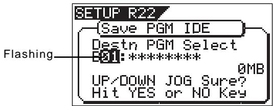
In the example above, the selected program data will be saved to a CD-RW/CD-R disc with the backup number "B01". The program title is copied to the backup title (you can not edit it).
By rotating the [JOG] dial when the above screen is shown, you can also select "Eject", besides "B01".
If you select "Eject" and then press the [ENTER/YES] key, the disc will be ejected.
- While "B01" is shown, press the [ENTER/YES] key.
The VF160EX starts the save operation. The recorded space shown on the display is counted down while the save operation progresses.
It will take some time for saving all data. The following display example shows that the data of the selected program number is being saved to the backup number "B01".
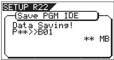
When completing the save operation, "Save Completed!" appears on the display (as shown below) and the VF160EX stops access to the drive, while the disc in the CD-R/RW drive is automatically ejected.
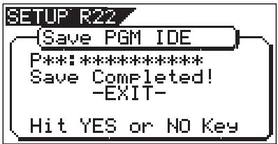
When saving data to more than one disc, the first disc will be ejected when it is full (i.e. there is no more recording space on the disc), while "Insert Disk!" appears on the screen. After inserting the second disc, the VF160EX automatically resumes the save operation.
After completing the save operation, the final disc is ejected and the above screen appears. (See below).
8. Press the [EXIT/NO] key (or the [STOP] key) to exit the Setup mode.
If you save data to more than one disc, we recommend to put a number on each disc in the saving order (such as DISC-1, DISC-2, etc.) so that you will easily know the order for inserting discs when loading data.
You cannot abort the save operation before completed. Especially during the save operation to more than one disc, if you happen to press the [EXIT/NO] key while removing or inserting a disc, you have to redo the save operation from the beginning with the first disc.
If an error occurs for some reason during the save operation, the error message as below appears.
If it appears, press the [EXIT/NO] key.
The display returns to the previous screen before performing the save operation.
Note that saved data before the error message appears is all invalid.
![FOSTEX VF160EX - Press the [EXIT/NO] key (or the [STOP] key) to exit the Setup mode. - 1](/content/2025/01/168450/images/530c351a6342ad51b40449c988298b76619d498eee45ea30e554499232180e50.jpg)
If the message above appears while saving data to a CD-R disc, you can no longer use the disc.
In the description for saving data above, we assume to use a non-recorded CD-RW/CD-R disc.
If you use a recorded disc (including a disc on which computer data is recorded), also note the following.
By performing step 5 in the save operation procedure shown above ("While "BkUp" is flashing, press the [ENTER/YES] key"). When a recorded disc is inserted, the display shows a warning message, followed by the confirmation screen (where "Sure?" flashes).
With this screen, you can choose whether erasing the recorded data or ejecting the disc.
![FOSTEX VF160EX - Press the [EXIT/NO] key (or the [STOP] key) to exit the Setup mode. - 1](/content/2025/01/168450/images/860e1bd6ad203d721bef242bdfce25b2b0c725cf3e9cb11c81e550a98a886e91.jpg)
To erase the existing (recorded) data
Press the [ENTER/YES] key while both "ERASE" and "Sure?" are flashing. The display shows the screen below and the VF160EX starts erasing the disc.
As the erase process progresses, the number of flashing **" increases from left to right.
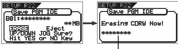
Increases as the process progresses.
Immediately after completing erasing the disc, the display shows the same screen (for selecting a program to be saved) which appears after step 5 is performed. Hereafter, perform the same procedure as described above.
The erasure operation described above is the "quick erasure". The VF160EX only erases special areas (TOC, etc.) and does not erase data area. If you repeatedly encounter a read error after carrying out the erasure operation above, try to carry out "full erasure" described on the next page.
To eject the disc
Use the [JOG] dial to highlight "Eject" (flashing) and press the [ENTER/YES] key.
The disc is ejected while the display shows "Insert Disk!". By inserting a disc, you can start the save operation again from the beginning.
If you try to save data to a recorded CD-R disc, the display shows a warning message saying "Not Writable", followed by a message saying "Insert Disk" as below.
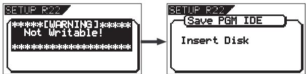
Carrying out "full erasure"
- While the recorder is stopped, press the [SETUP] key.
The display shows the SETUP menu.
- Use the [JOG] dial to select "Save PGM" and press the [ENTER/YES] key.
The display shows the screen for selecting the save device, where "IDE" flashes.
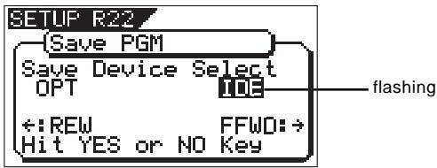
- While "IDE" flashes, press the [ENTER/YES] key.
The display now shows the screen for selecting the save mode, where "Bkup" flashes.
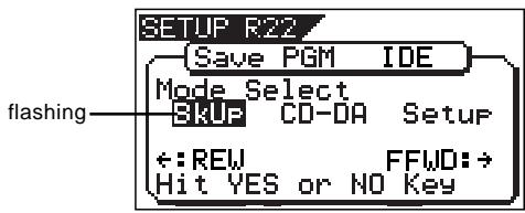
- Use the [JOG] dial to highlight "Setup" and press the [ENTER/YES] key.
The display now shows the screen for setting write condition, where "Copyright" is highlighted.
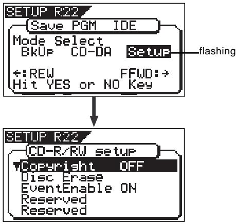
- Use the [JOG] dial to highlight "Disc Erase" and press the [ENTER/YES] key.
The display now shows the screen for selecting the erase mode, where "Quick" flashes.
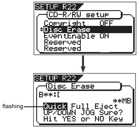
To carry out "Full erase", select "Full".
To carry out the "Quick erase" which is the same one as described on the previous page, select "Quick".
If you select "Eject", the disc is ejected.
- Use the [JOG] dial to highlight "Full" and press the [ENTER/YES] key.
The VF160EX starts erasing. When completing,
"Completed!" is shown.
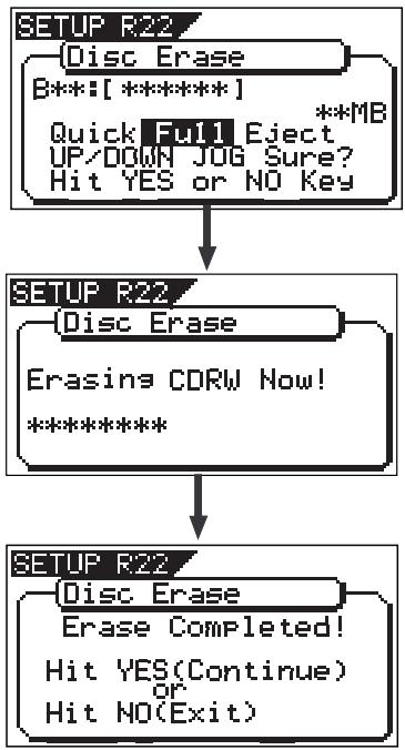
If the VF160EX cannot carry out "Full erase" by any reason, the display returns to show the screen for selecting the erase mode.
In such a case, try to carry out the same operation as described above.
- To "full erase" another disc, press the [ENTER/YES] key, followed by the procedure described in <How to
"full erase" another disc> below.
To exit the erase mode, press the [EXIT/NO] key.
Pressing the [ENTER/YES] key brings up the screen for selecting the erase mode shown above. Select "Eject" and press the [ENTER/YES] key. The disc already erased is ejected.
Then set another disc to be erased.
When setting the disc, the display automatically changes to the screen for selecting the erase mode.
Select "Full" as step 6 above.
The VF160EX starts full erasing.
Loading backup data from a CD-R/RW drive
The following description is assumed that you have a CD-RW/CD-R disc which contains saved data.
Do not carry out any VF160EX key operation until the access process to the CD-RW/CD-R disc is completed.
1. After turning on the VF160EX, insert the disc to the CD-R/RW drive.
If you load song data which is saved to more than one disc, set DISC-1 first.
If you set the other disc and go on the following procedure, the VF160EX automatically recognized that the disc order is not correct and the display shows "Wrong Disk", followed by "Illegal No!" momentarily, and the disc is automatically ejected.
2. Press the [SETUP] key to enter the setup mode.
The display shows the screen for selecting the setup menu.
3. Use the [JOG] dial to select (highlight) "Load PGM" and press the [ENTER/YES] key.
The display shows the screen for selecting a load device, where "IDE" is flashing.
![FOSTEX VF160EX - Use the [JOG] dial to select (highlight) "Load PGM" and press the [ENTER/YES] key. - 1](/content/2025/01/168450/images/f8688e2716248e94134eded7823bf9047bef86d648b2d9df2070baf691e9454a.jpg)
4. While "IDE" is flashing, press the [ENTER/YES] key.
Press the [ENTER/YES] key to display the CD-R/RW drive name, and then changes to the load mode select screen where "Bkup" (Backup) flashes.
To load saved data, select "BkUp". To load data from an audio CD, select "CD-DA".
Let's select "Bkup" here and go on to the following procedure.
See "loading from an audio CD" described later for details about how to use audio CD (CD-DA) discs.
![FOSTEX VF160EX - While "IDE" is flashing, press the [ENTER/YES] key. - 1](/content/2025/01/168450/images/53d771b51369ff395d102189f0c59629b51a27cb977df4fc669f69f9ae5fa3d5.jpg)
5. While "BkUp" is flashing, press the [ENTER/YES] key.
The display shows the backup number and title, as well as recorded space.
![FOSTEX VF160EX - While "BkUp" is flashing, press the [ENTER/YES] key. - 1](/content/2025/01/168450/images/007943644e0eabd0993a1654767c02fc5e006a0cd96e26ccd470e86d8033e0a3.jpg)
By rotating the [JOG] dial, you can select a desired program number/title from among available programs in the VF160EX current drive. You can also select "Eject". If you select "Eject" and press the [ENTER/YES] key, the disc is ejected
When you load song data which is saved to more than one disc, the display also shows the disc number currently set. The example below shows DISC-1 is set.
![FOSTEX VF160EX - While "BkUp" is flashing, press the [ENTER/YES] key. - 2](/content/2025/01/168450/images/43f0a61a5e30a903a4fa46752e976a0910a567048e380d7d9568de6b4937c08b.jpg)
6. While the desired backup number/title is shown on the display, press the [ENTER/YES] key.
The display shows the screen for creating a new program on the current drive, to which data will be loaded ("New PGM" lights).
![FOSTEX VF160EX - While the desired backup number/title is shown on the display, press the [ENTER/YES] key. - 1](/content/2025/01/168450/images/319a5269122bab8056d4bcf88254429fd6c46364f9cfdb623cd20519804959ff.jpg)
As described earlier, when loading data from a CD-RW drive, the VF160EX creates a new program on the current drive, which is the load destination. Therefore, "New PGM" is shown on the right of the flashing program number. The program number for the newly created destination program is the next number to the highest existing program number. For example, if there are 8 existing programs ("P01" through "P08") on the current drive, the newly created program is numbered "P09".
If you rotate the [JOG] dial while the above screen ("Destn PGM Select") is shown, you can select an existing program on the current drive as the destination. However, as mentioned earlier, when loading data using CD-RW you cannot actually load data to the existing program by overwriting the program data.
If you press the [ENTER/YES] key (see the next step) while selecting an existing program as the destination, the display shows "Void!" and the VF160EX ignores the operation.
7. While "New PGM" is shown, press the [ENTER/YES] key.
The VF160EX starts the load operation. The recorded space shown on the display is counted down while the load operation progresses.
It will take some time for loading all data. The following display example shows that the data of the backup number "B01" is being loaded to "P08" which is newly created on the current drive.
![FOSTEX VF160EX - While "New PGM" is shown, press the [ENTER/YES] key. - 1](/content/2025/01/168450/images/73b5bfdf0fb0c8e42e47b04ef69e1823bdde7ac28aa0d2c84fc71a01a3582709.jpg)
If there is not enough available space for loading on the current drive, the display shows "Disk Full!" and the display returns to the previous screen.
When completing the load operation, "Load Completed!" appears on the display (as shown below) and the VF160EX stops access to the drive, while the disc in the CD-R/RW drive is automatically ejected.
![FOSTEX VF160EX - While "New PGM" is shown, press the [ENTER/YES] key. - 1](/content/2025/01/168450/images/3f2a48d6700aee259c6b2e3bc7af2d424d5e2d34c6a18077cbd5103df94fc2f0.jpg)
When loading data from more than one disc, the first disc will be ejected immediately after all disc data has been loaded, while "Insert Disk!" appears on the screen. After inserting the second disc, the VF160EX automatically resumes the load operation.
After completing loading all the discs, the above screen appears.
You cannot abort the load operation before completed.
8. Press the [EXIT/NO] key (or the [STOP] key) to exit the Setup mode.
If an error occurs for some reason during the load operation, the error message as below appears. If it appears, press the [EXIT/NO] key.
The display returns to the previous screen before performing the load operation.
Note that loaded data before the error message appears is all invalid.
![FOSTEX VF160EX - Press the [EXIT/NO] key (or the [STOP] key) to exit the Setup mode. - 1](/content/2025/01/168450/images/5a6ca3ef7554becf0b30e4ae39bc3a1ddbed6ca390b321dc782c8c4a4d2873c2.jpg)
Save/load of WAV files using a CD-RW/CD-R drive
You can save or load a WAV file to or from a CD-RW/CD-R disc.
You can save data for only one desired program to a CD-RW/CD-R disc, regardless of the recording size. Even if a disc has enough recording space, you cannot record data for more than one program to it. If data size for a program is larger than the size of a disc, it can be saved using more than one disc.
About directory of a backup disc:
- A WAV file saved is recorded in the root directory (in the first layer) on the backup disc.
- A WAV file that can be loaded must be allocated in the root directory on the backup disc.
A WAV file moved from the root directory to another area such as a folder cannot be recognized by the VF160EX, which may cause a malfunction.
About file names of WAV file:
- A WAV file the VF160EX saves is recorded with a file name "**#.WAV."
- A WAV file the VF160EX can load must have a file name "**#.WAV."
The first 6 characters "**" are the title that is shown in the "Title Edit" screen in the Setup mode.
These characters can be changed when saving using a WAV file or edited by a computer.
The following 2 characters "##" indicate the track number (1 to 24) for the save/load using a WAV file.
The last ".WAV" is the file extension indicating that the file format is WAV.
The VF160EX does not recognize other file names than above. See the following description for each operation about details.
By using the specifications above, you can load only the desired tracks of a WAV file or load a track-swapped WAV file.
Saving a WAV file
The following description is assumed that an unused CD-RW/CD-R disc is set to the CD-R/RW drive.
1. Press the [SETUP] key to enter the Setup mode.
The display shows the screen for selecting the Setup menu.
2. Use the [JOG] dial to select "Save PGM" and press the [ENTER/YES] key.
The display shows the screen for selecting the device to which the data is saved. "IDE" flashes.
![FOSTEX VF160EX - Use the [JOG] dial to select "Save PGM" and press the [ENTER/YES] key. - 1](/content/2025/01/168450/images/ee947769c035212b5864ee49c34da47cedd7846ff4b1566f406ab6a77f0d93ff.jpg)
3. While "IDE" is flashing, press the [ENTER/YES] key.
The display shows the screen for selecting the save mode, where "BkUp" flashes.
![FOSTEX VF160EX - While "IDE" is flashing, press the [ENTER/YES] key. - 1](/content/2025/01/168450/images/e13e75f8687b681935f5a833475299981354178bafd85968d59d1b835ef036f4.jpg)
4. While "BkUp" is flashing, press the [ENTER/YES] key.
The display shows the screen for selecting the backup mode (FDMS3 or WAV), where "WAV" flashes.
![FOSTEX VF160EX - While "BkUp" is flashing, press the [ENTER/YES] key. - 1](/content/2025/01/168450/images/3ffdc7340de13eceaf617b06edfb66c956c4e735489e76c1f7494e83ee19512a.jpg)
5. While "WAV" is flashing, press the [ENTER/YES] key.
The display shows the screen for selecting On or Off of the Clipboard Export function, where "Off" flashes. You can switches between On and Off by using the [JOG] dial (or [REWIND] key/[F FWD] key).
![FOSTEX VF160EX - While "WAV" is flashing, press the [ENTER/YES] key. - 1](/content/2025/01/168450/images/d29c8f9806ffbd8f7bdcd0f5b36c6dc02ad8125b889743e867566a5a065d216f.jpg)
If you save all data from "ABS 0" to "REC END" (in most cases), you do not have to change the setting here.
The "Clipboard Export function" allows you to save the desired range of data between the Clipboard In and Out points which are set when executing the Copy-paste or Move-paste function.
Therefore, if you want to save only the specific range of data, you have to register the Clipboard In and Out points before the save operation.
See "Locate Function" in "Chapter 2 Basic Recording and Playback" for details about how to set the Clipboard In and Out points
If you save all data from "ABS 0" to "REC END", make sure to set the "Clipboard Export function" to "Off".
6. While "Off" is flashing, press the [ENTER/YES] key.
The display shows the screen for selecting a program to be saved. The program number currently selected flashes, while the data size of the program is shown.
![FOSTEX VF160EX - While "Off" is flashing, press the [ENTER/YES] key. - 1](/content/2025/01/168450/images/1c3b4e35db1b0be3539d857fd01648de8b56b138f957c90d69c26f9878787f74.jpg)
7. Use the [JOG] dial to select a program to be saved and press the [ENTER/YES] key.
The display shows the screen for selecting a track to be saved. Initially, "All Track" flashes.
![FOSTEX VF160EX - Use the [JOG] dial to select a program to be saved and press the [ENTER/YES] key. - 1](/content/2025/01/168450/images/910e9b270bb583074b176e33792bb9ee8fe7fc452124cd5cb536d1ff0affbf99.jpg)
By rotating the [JOG] dial (or press the [F FWD] key), you can select "From To*" (where the left field flashes initially) instead of "All Track".
If you save data for all tracks (1 through 24), select "All Track".
If you save data for any specific track (s), select "From To *" and specify the desired track numbers.
![FOSTEX VF160EX - Use the [JOG] dial to select a program to be saved and press the [ENTER/YES] key. - 2](/content/2025/01/168450/images/8d7f06c384070dbd2c06bb2c0a3075b027c5edba43e4e783180bd3d94db77956.jpg)
By rotating the [JOG] dial while the left ("From") field is flashing, you can select the track number from 01 through 24.
The number in the right ("To") field automatically follows the number in the left field (i.e. numbers in the left and right fields are always the same.)
Therefore, if you want to save a single track, you just have to set the right ("From") field and do not have to set the right ("To") field. For example, "From 02 To 02" will save only track 2.
To specify tracks 5 through 12:
- Enter "05" to the left field while the left field is flashing.
- Press the [F FWD] key to make the right field flashing.
- Enter "12". (Note that the number for the right field must be equal to or larger than the left field.)
Finally, the screen shows "From 05 To 12" to save tracks 5 through 12.
8. After selecting the track(s), press the [ENTER/YES] key.
The display shows the screen for selecting a WAV file on the disc.
You can select "Eject" by rotating the [JOG] dial.
To remove the disc, select "Eject" and press the [ENTER/YES] key.
![FOSTEX VF160EX - After selecting the track(s), press the [ENTER/YES] key. - 1](/content/2025/01/168450/images/aa72dd166c7bb9d117857b422fa8280136e6cc3ebe15533aa477fd2b622dfeb4.jpg)
9. While "WAV" is flashing, press the [ENTER/YES] key.
The display shows the screen for editing the WAV file.
![FOSTEX VF160EX - While "WAV" is flashing, press the [ENTER/YES] key. - 1](/content/2025/01/168450/images/abf879cf816e550514b1047b5c8b7661e7f8cbaf979715356a5187515477dd53.jpg)
By rotating the [JOG] dial, you can set the desired numeric, symbolic or alphabetical character to the flashing point. You can move the flashing point by using the [F FWD] key or [REWIND] key. See the following table for the available characters.
Upper-case alphabetical characters (A to Z) Numerals (0 to 9)
Symbols (!#$%&' (@ ^_)-
You can use up to 6 characters for a file name.
Some characters entered are converted as shown below.
- Upper-case alphabetical characters (A to Z): not converted.
- Lower-case alphabetical characters (a to z): converted to the corresponding upper-case.
• Numerals (!# $ % & ' ( ) @ ^ _ -.): not converted.
- Other symbols: converted to "_".
10. After entering the file name, press the [ENTER/YES] key.
The save operation is executed and the display shows something like the one as below. As the file save goes on, the remaining data size shown on the screen counts down.
![FOSTEX VF160EX - After entering the file name, press the [ENTER/YES] key. - 1](/content/2025/01/168450/images/4b9ca3d0a4b8f18617a4ac80124636da987dd1f4e9a27a11aeeafdfb0b404d06.jpg)
Immediately after the data save to each disc is completed, the disc is automatically ejected, and "Insert Disk" flashes on the screen, prompting you to insert the next disc. Inserting the next disc resumes the save operation.
After the save operation is completed, "Save Completed!" appears on the screen.
![FOSTEX VF160EX - After entering the file name, press the [ENTER/YES] key. - 2](/content/2025/01/168450/images/9a7e2e196c61c4ecbe311590b754086eba2d0df0c82f1fcc4cd25f2da64a785e.jpg)
- Press the [EXIT/NO] key (or the [STOP] key) repeatedly until exiting the Setup mode.
When using a CD-RW or CD-R disc on which program data is recorded, pressing the [ENTER/YES] key while "BkUp" is flashing brings up the warning message, followed by the screen for erasing the existing file, as shown below.
![FOSTEX VF160EX - After entering the file name, press the [ENTER/YES] key. - 1](/content/2025/01/168450/images/279b41dc2ef3037824947bbf8db53023acc6a96d2b11d798e35a7ffcfabd3ad4.jpg)
To erase the existing file, select "ERASE" and press the [ENTER/YES] key.
If you do not want to erase the file, select "Eject" and press the [ENTER/YES] key. The disc is ejected and you can replace the disc with another one.
Use the [JOG] dial (or the [REWIND]/[F FWD] keys) to select "ERASE" or "Eject".
The erasure operation described above is the "quick erasure". The VF160EX only erases special areas (TOC, etc.) and does not read error after carrying out the erasure operation above, try to carry out "full erasure" described on page 117.
WAV file structure.
A WAV file on the CD-RW/CD-R disc has 24 files (one file per track) in the root directory of the disc.
The file names are "**01.WAV" through "*24.WAV" where "***" shows the file name specified in step 8 and each number
(01 - 24) shows the corresponding track number.
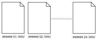
WAV file structure which is saved over more than one disc.
A WAV file is saved in order of track number (from tracks 1 to 24).
During the save operation over more than one CD-RW/CD-R disc, the VF160EX always calculates the available space of the disc automatically. If the VF160EX knows that the available space gets smaller than the data size of the next track, it will change the disc when the data save of the current track is completed.
WAV file size
When saving data by the WAV file format to a CD-RW/CD-R disc, the file size may sometimes increase compared with the data size in the current drive, depending on the recorded data condition such as the start time, end time, the data amount, etc. on each track. For example, if a track is recorded from ABS: 0 (min.) to ABS: 1 (min.) and ABS: 10 (min.) to ABS: 11 (min.), the file on the current drive has a length of 2 minutes, while the WAV file has a length of 11 minutes.
Loading a WAV file
The following description is assumed that a CD-RW/CD-R disc which contains saved data is set to the CD-R/RW drive.
1. Press the [SETUP] key to enter the Setup mode.
The display shows the screen for selecting the Setup menu.
2. Use the [JOG] dial to select "Load PGM" and press the [ENTER/YES] key.
The display shows the screen for selecting the device from which the data is loaded. "IDE" flashes.
![FOSTEX VF160EX - Use the [JOG] dial to select "Load PGM" and press the [ENTER/YES] key. - 1](/content/2025/01/168450/images/ae1c7d1aae5d36bb91c554a05e37ba84b8b26dfab07c02142fb0e7a07d66b111.jpg)
3. While "IDE" is flashing, press the [ENTER/YES] key.
The display shows the drive name, followed by the screen for selecting the WAV file to be loaded, showing the WAV file name and size.
![FOSTEX VF160EX - While "IDE" is flashing, press the [ENTER/YES] key. - 1](/content/2025/01/168450/images/0fa55a0cfecddf64507e6be977d6ecda3c9846cda892376d5280144cb9bb8d72.jpg)
4. Use the [JOG] dial to select the desired WAV file to be loaded.
If more than one WAV file with different file names (the first 6 characters) is saved, you can see each file name (by the first 6 characters) in order when rotating the [JOG] dial. You can also select "Eject" to remove the CD-RW/CD-R disc.
The VF160EX cannot recognize any other file names but
"**#.WAV" and cannot load such discs.
A WAV file with an unique name (the first 6 characters) is recognized as an independent backup file and can be selected.
5. After selecting the desired WAV file, press the [ENTER/YES] key.
The display shows the screen for selecting a track to be loaded. "All" flashes initially.
![FOSTEX VF160EX - After selecting the desired WAV file, press the [ENTER/YES] key. - 1](/content/2025/01/168450/images/86499117062b6fba2f815edcee6f8287429df30f4152181a4920f128cfcfb589.jpg)
Besides "All", you can select any one of tracks (01 through 24) by rotating the [JOG] dial.
![FOSTEX VF160EX - After selecting the desired WAV file, press the [ENTER/YES] key. - 2](/content/2025/01/168450/images/f14c346020c252322d164afeaa6b2b150fd88df74dde9ed15c45ddecd47ebeef.jpg)
6. After selecting the desired track(s), press the [ENTER/YES] key.
The display shows the screen for selecting the load destination program to which a WAV file is loaded. You can select the program by using the [JOG] dial.
![FOSTEX VF160EX - After selecting the desired track(s), press the [ENTER/YES] key. - 1](/content/2025/01/168450/images/c72967e962f5e0da287199dec3f17f0ca772877361a5ff68150d17c613a1ab6a.jpg)
When the screen shows "Title" and "size", the selected program will be deleted and replaced with the WAV file loaded.
When the screen shows "Title" and "New PGM", the WAV file loaded will create a new program.
If the current drive does not have enough available space for loading the WAV file, the size indication on the screen shows a negative value ("-***").
In such a case, select a program that can be replaced with the WAV file loaded without causing the disc space shortage, or delete unnecessary programs by the "delete PGM" menu in the Setup mode.
7. After selecting the load destination program, press the [ENTER/YES] key.
When selecting a new program as the load destination (by selecting an option showing "Title" and "New PGM"), the load operation immediately starts.
When selecting an existing program as the load destination (by selecting an option showing "Title" and "Size"),
"Overwrite?" and "Sure?" appear.
Pressing the [ENTER/YES] key will start the load operation. During the load operation, the screen shows something like the one as below.
As the data load goes on, the remaining data size shown on the screen counts down.
![FOSTEX VF160EX - After selecting the load destination program, press the [ENTER/YES] key. - 1](/content/2025/01/168450/images/9a46fa32621497bc353f7049b7fceed5a49baab60dff387807257f256420600d.jpg)
When the load operation is completed, "Load Completed!" appears on the screen.
The title of the program to which the WAV file is loaded is replaced with the WAV file name loaded (the first 6 characters).
8. Press the [EXIT/NO] key (or the [STOP] key) repeatedly until exiting the Setup mode.
To go back to the previous step or about the operation, you can also use the [EXIT/NO] key or the [STOP] key.
Making an audio CD
This section describes how to make an audio CD (CD-DA) using a CD-RW/CD-R disc from mixed-down materials created by the internal mixdown mode. See details for the internal mixdown mode on page 79.
The "Save PGM" menu in the Setup mode, which is used for saving song data, is also used for making an audio CD.
When making an audio CD using the VF160EX, mixed-down materials on the current drive are recorded to a CD-RW/CD-R disc (by the CD-DA format).
Only data between the CLIPBOARD IN and CLIPBOARD OUT points of the mixed-down program is recorded to a CD-RW/CD-R disc. You can record more than one material to a disc successively.
If an audio CD is made using a CD-RW disc, it can be played back only by a player that supports CD-RW playback. You cannot playback such a disc by a conventional CD player that does not support CD-RW playback.
In the following operations, we assume that there are one or more programs which are mixed down by the internal mixdown mode on the current drive.
Key operations of the VF160EX should be done after completing access to a CD-RW/CD-R disc.
- After turning on the power of the VF160EX, load a non-recorded disc to the CD-R/RW drive.
- Press the [SETUP] key to enter the Setup mode.
- Use the [JOG] dial to select (highlight) the "Save PGM" menu and press the [ENTER/YES] key.
The display shows the screen for selecting the device to which the data is saved. "IDE" flashes.
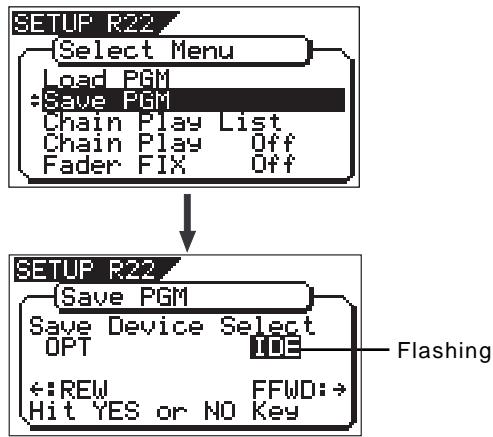
- While "IDE" is flashing, press the [ENTER/YES] key.
By pressing the [ENTER/YES] key, the display shows the CD-R/RW drive name, and then changes to the save mode select screen where "Bkup" (Backup) flashes.
To carry out making an audio CD, select "CD-DA".
If you need to change the copy protection setting (the default setting is "OFF") and event enable setting (the default setting is "ON"), select "Setup" (for setting writing conditions). If you make an audio CD without changing the copy protection setting, skip steps 5 and 6 below and go to step 7.
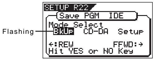
- Use the [JOG] dial to select "Setup" and press the [ENTER/YES] key.
The display shows the "CD-R/RW Setup" screen, on which you can select the copy protection setting and event enable setting.
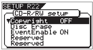
Copy protection setting
You can restrict the disc copy (duplication) capability of an audio CD you are going to make.
| ON | A disc you made can be copied to other digital device once. |
| OFF | A disc you made can be copied to other digital device as many times as required (default). |
Event Enable setting
This setting allows you to select whether enabling (ON) or disabling (OFF) the events stored between the clipboard in and clipboard out points when burning a material to an audio CD. See page 128 for details.
| ON | Enables events between the clipboard in and out points. When making an audio CD, a mastered material is divided into tracks separated by the events (default). |
| OFF | Disables events between the clipboard in and out points. When making an audio CD, a mastered material is not divided into tracks (i.e. a material is burned as a single track). |
To change the setting, press the [ENTER/YES] key when the "CD-R/RW Setup" screen is shown. The current setting starts flashing, showing it can be edited. While flashing, use the [JOG] dial to select "ON" or "OFF", then press the [ENTER/YES] key to confirm.
6. After setting the copy protection and event enable, press the [EXIT/NO] key.
The display returns to the screen for selecting the save mode, in which "CD-DA" now flashes.
![FOSTEX VF160EX - After setting the copy protection and event enable, press the [EXIT/NO] key. - 1](/content/2025/01/168450/images/2c1cfd948032a1e2757c08939fc575908ff1d4105267a30d7895c30f1cff54ee.jpg)
7. While "CD-DA" is flashing, press the [ENTER/YES] key. After showing "Please Wait!", the display shows the screen for selecting the program(s) to be record.
In the screen, a number such as "01" or "02" shows the track number, while "NON" shows that no program is assigned to the track.
![FOSTEX VF160EX - While "CD-DA" is flashing, press the [ENTER/YES] key. After showing "Please Wait!", the display shows the screen for selecting the program(s) to be record. - 1](/content/2025/01/168450/images/1233ea3972f530ee7e5515ba22c08b8578d2053cc3c31abc7947c4290f59734b.jpg)
8. Press the [ENTER/YES] key again.
The highest program number available on the current drive starts flashing and its program title and the recording time are also shown. At the top of the program table, the total time of the program is shown.
![FOSTEX VF160EX - Press the [ENTER/YES] key again. - 1](/content/2025/01/168450/images/ce120a8be99fa39d35f63a5da184179667a3016e9ab86d5dd54a2043d4b6d3ea.jpg)
9. Use the [JOG] dial to select a desired program and press the [ENTER/YES] key.
The selected program is set to the first track.
![FOSTEX VF160EX - Use the [JOG] dial to select a desired program and press the [ENTER/YES] key. - 1](/content/2025/01/168450/images/a7490af537acfc1b8865378089b65a2fdeaf66ea3096e2d8240389ffa90976e9.jpg)
- To record a single song to a CD-RW/CD-R disc, select a program and press the [ENTER/YES] key, and then go to step 10.
- To record more than one song to a CD-RW/CD-R disc, repeat the procedure for selecting a program described above (i.e. use the [JOG] dial to select a program and press the [ENTER/YES] key) until selecting all desired programs, and then go to step 10.
If the program time shows "00:00" when selecting a program as the screen example below, the CLIPBOARD IN and CLIPBOARD OUT points are not correctly set.
![FOSTEX VF160EX - Use the [JOG] dial to select a desired program and press the [ENTER/YES] key. - 1](/content/2025/01/168450/images/04319f496d5b648c80deee6a5afa200c85e134c104f5e7349ec79cecd777d29a.jpg)
In other words, in the following conditions, the CLIPBOARD IN and CLIPBOARD OUT points are not regarded as being correctly set.
CLIPBOARD IN point = CLIPBOARD OUT point
CLIPBOARD IN point > CLIPBOARD OUT point
If you press the [ENTER/YES] key after selecting such a program, the warning message as below appears on the display and you cannot select the program.
"Void In!", "Void Out!", or "Void Data!"
It is possible to select a program that is not mixed down if it holds the correct "IN" and "OUT" points. However, if you record such a program to a CD-RW/ CD-R disc with the audio CD format, only track 1 and 2 can be recorded.
So, make sure that you select programs properly when making an audio CD.
When recording more than one program to a CD-RW/CD-R disc, do not skip any track when assigning programs to tracks.
If you skip any track, you cannot record data to the subsequent tracks. In the following example, track 03 is skipped when assigning programs.
So only tracks 01 and 02 will be recorded. Tracks 03 and subsequent tracks can not be recorded.
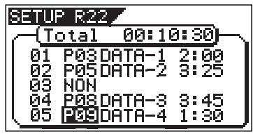
When making an audio CD, if you select a program which consumes more disc space than the recordable space of a CD-RW/CD-R disc, "Disk Full!" appears on the display and you cannot select the program.
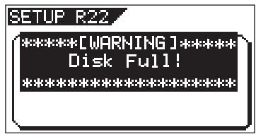
10. After specifying the program(s), press the [ENTER/YES] key while holding down the [RECORD] key.
The VF160EX starts recording to the disc, while the display shows the following screen.
![FOSTEX VF160EX - After specifying the program(s), press the [ENTER/YES] key while holding down the [RECORD] key. - 1](/content/2025/01/168450/images/26b28e49a8592756efadc6145fefadb9bf9b4b95b257d016cd9e6ecd7fca4540.jpg)
When the recording ends, "Save Completed!" appears on the screen, while the disc is automatically ejected from the CD-R/RW drive.
11. When completed, press the [EXIT/NO] key (or [STOP] key) to quit the Setup mode.
When a CD-RW disc on which any data is recorded is set, if you perform step 7 above (i.e. pressing the [ENTER/YES] key when "CD-DA" is flashing), "Not Empty!" appears on the display, followed by the screen for selecting whether erasing recorded data or ejecting the disc.
![FOSTEX VF160EX - When completed, press the [EXIT/NO] key (or [STOP] key) to quit the Setup mode. - 1](/content/2025/01/168450/images/921999fe71322ce001a824db7a0fca66cf775507b87fed9f6d56034f5ed6bc0d.jpg)
- If you erase recorded data:
Press the [ENTER/YES] key while "ERASE" and "Sure?" are flashing. After the key press, the display changes as follows and the unit starts erasing the data. As the erasing process is going on, the number of flashing "*" increases.
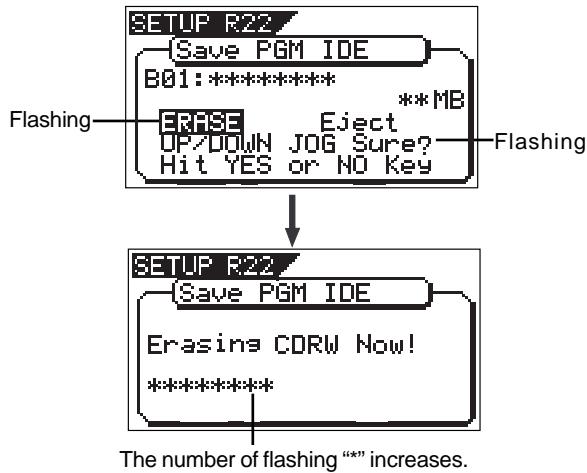
When erasing is completed, the display shows the same screen which appears when pressing the [ENTER/YES] key after selecting "CD-DA" on step 7 above. So follow the same procedure from step 8 on page 126.
The erasure operation described above is the "quick erasure". The VF160EX only erases special areas (TOC, etc.) and does not read error after carrying out the erasure operation above, try to carry out "full erasure" described on page 117.
If you eject the disc:
Use the [JOG] dial to make "Eject" flashing and then press the [ENTER/YES] key.
The disc is ejected, while "Insert Disk!" appears on the screen.
When inserting a blank disc, you can go on the next step (see the procedure described above).
The Event Enable setting selects enabling or disabling events registered between the Clipboard In and Out points of a material which is internally mastered for creating an audio CD.
Normally, when mastering a song using the internal mixdown function, the Clipboard In and Out points are automatically set (see the figure below). The Clipboard In point acts as "event" at the beginning of the song. By default, the "Event Enable" is set to "ON" (enabled). Therefore, when recording to a CD-R/RW disc, the VF160EX recognizes the material between the Clipboard In and Out points as a song (track).
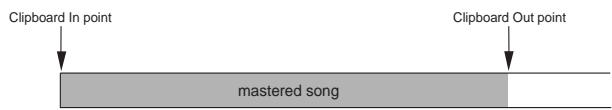
However, if a mastered song has any event(s) (besides the Clipboard In point), set "Event Enable" to "OFF". Note that the Clipboard In point is always recognized as "EVT 00" regardless of the "Event Enable" setting. The figure below shows the example of a mastered song which has events.
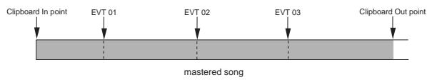
If you record a song which has events (as above) to a CD-R/RW disc while "Event Enable" is set to "ON", the song is divided into tracks by events (see the figure below).
Therefore, when creating an audio CD from a mastered song which has any event(s), make sure that "Event Enable" is set to "OFF", in order to ignore the event(s) except the Clipboard In point (EVT 00) and prevent the song from being divided into tracks.
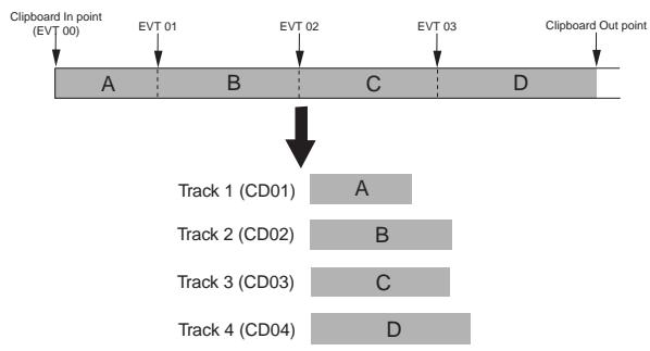
<"Event Enable" should also be set to "OFF" in such a case!>
Let's assume that there are two programs; program 1 and program 2. The material in program 1 has events, while the material in program 2 does not (as shown in figure below).
If you make an audio CD from these two materials, burn a disc with "Event Enable" set to "OFF". In result, you can make an audio CD containing two tracks (ignoring events on program 1).
If you burn a disc with "Event Enable" set to "ON", program 1 is divided into four tracks. In result, a CD containing five tracks (four from program 1 and one from program 2) is made.
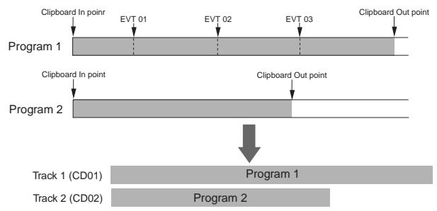
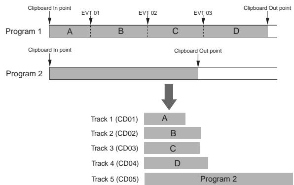
<"Event Enable" should be set to "ON" in such a case!>
When loading more than one track from an audio CD you made to the VF160EX hard disk, all the tracks are loaded onto a single program (see "Loading from an audio CD" on the next page for details), in which a event is automatically set to the beginning of each track.
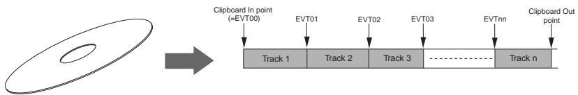
When making an audio CD from a program which has been loaded from an audio CD and contains more than one track, set "Event Enable" to "ON". This allows making a CD which contains the same number of tracks as the number of tracks loaded from an audio CD.
Loading from an audio CD
You can load a desired song to the unit from an audio CD you created by recording on a CD-RW/CD-R disc. When a desired song is loaded, the unit automatically creates a new program on the current drive, and the song are recorded on tracks 1 and 2 of the program. Loading data from an audio CD is operated via the "Load PGM" menu in the Setup mode, which is the same way as loading backup data.
You can also load a material from a commercially available audio CD in the same manner, however, never use a material for which a copyright is reserved for a commercial purpose.
Any unauthorized use will constitute infringement of such copyright and will render the infringer liable to an action at low. Please remember that data included in a commercial audio CD (CD-DA) with copy protection being turned on cannot be loaded into VF160EX.
The following description is assumed that you have an audio CD created by the VF160EX (or a commercially available audio CD).
Key operations of the VF160EX should be done after completing access to a CD-RW/CD-R disc.
- After turning on the power of the VF160EX, load a recorded audio CD disc to the CD-R/RW drive.
- Press the [SETUP] key to enter the Setup mode.
- Use the [JOG] dial to select (highlight) the "Load PGM" menu and press the [ENTER/YES] key.
The display changes to show the screen for selecting the source device of loading, on which "IDE" flashes.
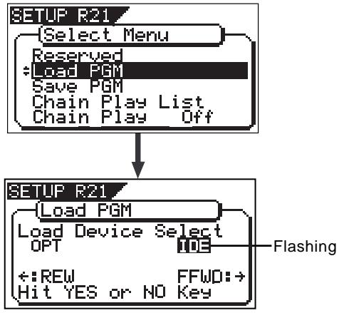
- While "IED" is flashing, press the [ENTER/YES] key.
The display changes to show the screen for selecting the load mode, on which "CD-DA" flashes.
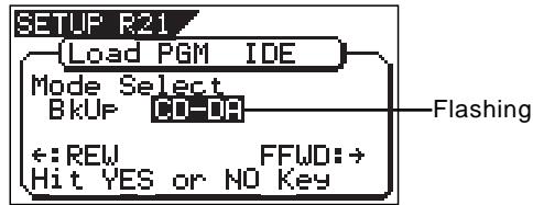
- While "CD-DA" is flashing, press the [ENTER/YES] key.
The display now shows the warning message for the copyright. By rotating the [JOG] dial, you can scroll the message.
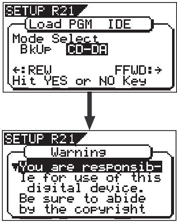
The warning message for copyright shown on the screen is as follows.
Warning!
You are responsible for use of this digital device. Be sure to abide by the copyright conditions of the source material.
Press "Enter/Yes" key if you agree with the above.
If you do not agree with the warning message contents, press the [EXIT/NO] key to quit loading.
The display briefly shows "Set Disable" and "Can't Loading", then returns to the mode select screen.
If you agree with the warning message contents, go to the next step to continue the operation.
When loading data using the S/P DIF digital signal, the same message also appears after selecting the load device to "SP DIF" and pressing the [ENTER/YES] key.
- If you agree to the message contents, press the [ENTER/YES] key.
The display changes to show the screen for selecting the load type, on which "One" flashes.
You can select a desired load type from among "One", "Select" and "All". See the following table for details about each load type.
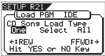
| One | You can select one or more tracks to be loaded. Each selected track is individually loaded to a new program automatically created on the current drive. |
| Select | You can select one or more tracks to be loaded. All the selected tracks are individually loaded to a new program automatically created on the current drive. |
| All | All the tracks on an audio CD are loaded to a new program automatically created on the current drive. |
| * “A new program automatically created on the current drive” has the program number one higher than the current highest program number. |
7. Select the desired load type and press the [ENTER/YES] key.
Depending on the selected load type, the display shows as below.
- When selecting "One" or "Select":
The screen as shown below appears.
The left column shows the track numbers (01, 02...) of the audio CD, while "NON" in the second column shows no program is selected.
"▼" is shown when more than one track is recorded on the audio CD. It is not shown when only one track is recorded on the audio CD. If only one track is recorded on the audio CD, "▼" is not shown. To select desired tracks to be loaded, go to step 8.
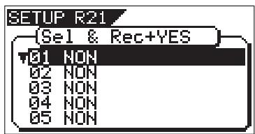
- When selecting "All":
All tracks on the audio CD are selected to be loaded, and the screen as shown below appears. In this screen example, the destination program newly created on the current drive is "P05". Each track time is also shown.
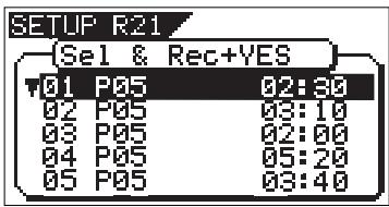
When loading from a audio CD, no title is shown when selecting the track.
When selecting "All", you can start loading tracks to the current drive by pressing the [ENTER/YES] key while holding down the [RECORD] key.
You can delete an unnecessary track if you want. See below about how to do it.
Before executing "All" track loading, you can delete an unnecessary track by the following procedure.
1) While the display shows the screen as above, use the [JOG] dial to highlight the desired track and press the [ENTER/YES] key.
The destination program number of the selected track starts flashing.
2) Use the [JOG] dial to select "NON" and press the [ENTER/YES] key.
A track whose destination program number is set to "NON" is not loaded.
8. Use the [JOG] dial to select (highlight) a desired track to be loaded and press the [ENTER/YES] key.
The load destination program number of the selected track is shown as a flashing display, as well as the track time. In the screen example below, track 1 (01) is selected. The total time is also shown above the track list. (The total time is summed up each time you select another track.)
![FOSTEX VF160EX - Use the [JOG] dial to select (highlight) a desired track to be loaded and press the [ENTER/YES] key. - 1](/content/2025/01/168450/images/76872c0a0749b55de7bf6deaa29c075014d6ff0a4987c213157cec51d93e7f5d.jpg)
In this condition, you can choose the option between "Pxx" (program number) and "NON" using the [JOG] dial. To cancel the track selection, choose "NON" and press the [ENTER/YES] key. To set the track to be loaded, go to the next step.
9. Press the [ENTER/YES] key.
The selected track ("01", in this example) is set, while the screen changes as below.
![FOSTEX VF160EX - Press the [ENTER/YES] key. - 1](/content/2025/01/168450/images/78d4d1d457151580538a9dc311c40bba4d5b8696574f454a1d41a9ae4f141988.jpg)
10. Use the [JOG] dial to select (highlight) another desired track to be loaded and press the [ENTER/YES] key.
In the example below, track 2 (02) is selected (of course, you can select whichever track you want). Depending on the load type ("One" or "Select") selected in step 7 above, the screen shown is slightly different.
When you set the load type to "One", the load destination program number for the secondly selected track is one higher than that for the firstly selected track. That is, the load destination program number is counted up each time you select a track.
On the contrary, when you set the load type to "Select", the load destination program number for the secondly selected track is same as the firstly selected track. That is, all selected tracks are loaded to the same program.
![FOSTEX VF160EX - Use the [JOG] dial to select (highlight) another desired track to be loaded and press the [ENTER/YES] key. - 1](/content/2025/01/168450/images/5e341f1268003cf830cb715b6185a365145748b3b18791fa4e0071b7295d4f54.jpg)
11. Press the [ENTER/YES] key.
As with the firstly selected track, the secondly selected track ("02", in this example) is set.
12. Operate the same procedure as above for selecting other tracks.
- When completing selecting all desired tracks, press the [ENTER/YES] key while holding down the [RECORD] key. The display shows "Data Loading!" while the remaining data amount (in MB) is counted down. You cannot cancel loading once it starts. Wait for a while until loading is completed. Loading more amount takes more time. When completing loading, "Load Completed!" is shown, while the audio CD is automatically ejected from the CD-R/RW drive.
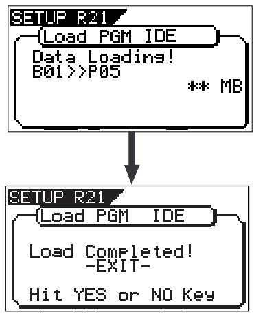
14. Press the [EXIT/NO] key to exit the setup mode.
If you are going to load tracks 1 and 3 in the example above, instead of tracks 1 and 2, track 3 will be loaded to program 06 (see the screen example below).
![FOSTEX VF160EX - Press the [EXIT/NO] key to exit the setup mode. - 1](/content/2025/01/168450/images/a33408e3a79a6c1bbf86200f9ea80d8fac24237e09295ad044471be8ce3fe3ab.jpg)
However, if you select track 2 after selecting tracks 1 and 3, the unit automatically reassigns track 2 to program 06 and track 3 to program 07 (see the screen example below).
![FOSTEX VF160EX - Press the [EXIT/NO] key to exit the setup mode. - 2](/content/2025/01/168450/images/b3455336160026979242764a4a841584960ec9b8edd13a1dbc8d8c7ce4cbd7f4.jpg)
To play back a desired loaded track on the current drive, carry out the following operation depending on the load type.
- To play back a track loaded with the type set to "One":
- Select the appropriate program to which the track to be played back is loaded by following the procedure below.
See "Selecting a program" on page 71 of the owner's manual for details about how to select a program.
1-1. Press the [PGM SEL] key.
1-2. Use the [JOG] dial to highlight the appropriate program.
1-3. Press the [ENTER/YES] key.
2. Press the [PLAY] key to start playback of the track.
- To play back tracks loaded with the type set to "Select" or "All":
- Select the destination program by following the same procedure as step 1 above.
- Select a desired track in the program by pressing the [REWIND/PREV] or [F FWD/NEXT] keys while holding down the [SHIFT] key when the recorder is stopped or during playback.
Because all the tracks loaded take part in the same program, you have to select a track within the program.
The VF160EX automatically set an event at the beginning of each track loaded with the type set to "Select" or "All", so pressing [REWIND/PREV] or [F FWD/NEXT] key while holding down the [SHIFT] key locates to the beginning of the previous or next track, as with a typical CD player on the market (see "Event function" on page 36).
3. Press the [PLAY] key to start playback of the track.
To check events, press the [SCENE STORE/MAP] key while holding down the [SHIFT] key while the recorder is stopped. The display shows the event map, allowing you to check the event positions (in the screen example below, the time base is set to "Bar/Beat/Clk").
![FOSTEX VF160EX - Press the [PLAY] key to start playback of the track. - 1](/content/2025/01/168450/images/f3c06bfb0aa0103e07edd088d70c2ea997d64199dc4ff245b3f7f65d6ea5ef58.jpg)
Chapter 7 SETUP mode
The SETUP mode of the VF160EX offers the "Changing the initial settings" menus, which configure the operating environment of the VF160EX, a "Check" menu that enables you to check the number of events for each track, and an "Execution" menu that executes certain operations, such as save and load and disk formatting. The "Changing the initial settings" menu includes 21 parameters as shown in below. These parameters were set before the VF160EX was shipped from the factory and these values are called the "initial settings." Modifying these settings allows you to change the operating environment of the VF160EX. The "Check" menu provides two parameters "Checking the number of events" as shown in - "Checking the number of events" and "Checking the current drive information."
Also, as shown in , the "Execution" menus include five items: Title Edit, Delete PGM, Load PGM, Save PGM, and Disk Format, which you can execute by selecting the corresponding SETUP menu. This chapter explains how to use the "Changing the initial settings" menus shown in and the "Check" menu shown in .
For more information on the "Execution" menus, refer to the corresponding pages in the "Reference page" column in .
"Changing the initial settings" menu
| Parameters | Display | Default setting | Refer page | Community |
| Setting a time signature | Signature Set | 001BAR 4/4 | 133 | ○ |
| Setting a tempo | Tempo Set | 001BAR 1,120 | 135 | ○ |
| Setting the metronome function | Click | Off | 136 | ○ |
| Setting a preroll time | Preroll Time | 00s | 137 | ○ |
| Setting MIDI sync output signal | Midi Sync Out | CLK | 137 | ○ |
| Setting an MTC frame rate | Frame Rate | 25 frame | 138 | ○ |
| Setting an MTC offset value | Mtc Offset | 00h 59m 57s 00f 00sf | 138 | ○ |
| Setting the offset mode | Offset Mode | ABS | 139 | ○ |
| Setting the slave mode | Slave Mode | Off | 139 | ○ |
| Setting the slave type | Slave Type | Vari | 140 | ○ |
| Setting the record protect function | Rec Protect | Off | 140 | ○ |
| Setting digital input | Digital In | Analog | 141 | ● |
| Setting digital output | Digital Out | SPDIF | 142 | ● |
| Setting BAR/BEAT resolution mode | Resolution | Off | 142 | ● |
| Setting the MIDI device ID number | Device ID | 00 | 143 | ● |
| Setting the fader fix mode | Fader Fix | Off | 145 | ○ |
| Setting the fader recall mode | Fader Recall | Off | 145 | ○ |
| Setting the pair fader | Pair Fader Set | Off | 146 | ○ |
| Setting the phantom power | Phantom Power | Off | 147 | ● |
| Setting the compressor channel | Comp. Channel | Off | 148 | ○ |
Modes applicable program by program. They can be saved/loaded.
- Modes applicable to all program. They cannot be saved/loaded.
- The above "Default setting" is the figure immediately after formatting the current drive.
“Check”menu
| Check item | Display | Refer page | Community |
| Check of the event number on the track | Number Of Event | 143 | - |
| Check of the current drive information | Drive Information | 144 | - |
"Execution" menu
| Execution item | Display | Refer page | Community |
| Editing a program title | Title Edit | 71 | - |
| Deleting a program | Delete | 71 | - |
| Saving song data to an external device | Load PGM | 106 | - |
| Loading song data from an external device | Save PGM | 106 | - |
| Formatting an current drive disk | Disk Format | 23 | - |
To enter the SETUP mode
Entering the SETUP is possible only when the VF160EX is in the Stop mode.
1. While the recorder is stopped, press the [SETUP] key on the operating panel.
When the [SETUP] key is pressed, the recorder enters the SETUP mode first stage and change to the display for selecting the SETUP menu. The white black reversed title indicates the currently selected menu and the (flash) indicates that other titles exist below.
![FOSTEX VF160EX - While the recorder is stopped, press the [SETUP] key on the operating panel. - 1](/content/2025/01/168450/images/8a168b3b3d79b8be636bbbaa82d7892e853f31e8aa4ad6f9d9ab93efcd6924e8.jpg)
At shipping from the plant or when power is switched on again, the "Signature Set" menu will be reversed in white-black. Otherwise, when exiting from the SETUP mode, the SETUP menu that was displayed last will be reversed in black and white.
2. If the desired menu is selected via the [JOG] dial and the [ENTER/YES] key pressed, you can proceed to the actual setup procedure.
- To exit from the SETUP mode or return to the previous level, press the [EXIT/NO] key (or [STOP] key).
- When selecting the desired SETUP menu, the [HOLD/>], [REWIND] and [F FWD] keys can be used in addition to the [JOG] dial.
Time signature setting ["Signature Set"]
Using the "Setting a time signature" menu, you can set a time signature of a given measure on the internal programmable Tempo Map. Also in this setting, the BAR (-002BAR, 1 一 , 00CLK) displayed at the head of the disk in the time base BAR/BEAT/CLK can be set within a range of "-009BAR" ~ "-002BAR".
For example, you can specify 4/4 for the first and second measures, and 2/2 from the third measure."
Setting a time signature and tempo will create a Tempo Map, which allows the VF160EX to manage a song using the BAR/BEAT/CLK Time Base. You can also use the Metronome function.
A time signature and tempo setting are required when MIDI clock & song position pointer are output to an external sequencer.
- Initial Setting : “001bar 4/4 beat”
- Available bars : “001” ~ “999”
- Available time signature : 1/4, 2/4, 3/4, 4/4, 5/4, 1/8,
3/8, 5/8, 6/8, 7/8, 8/8, “DEL”
- Maximum setting points : “64”
- The setting is applicable song by song.
- The setting can be saved or loaded as a part of the song data
- The setting is memorized even when the power is off.
- Make sure you choose the right program before setting this mode.
1. Select a program for which to set a time signature.
2. In the menu selecting display, select "Signature Set" and press the [ENTER/YES] key.
The display will change to confirming the currently set signature. In the initial setting, the display will be as shown below to indicate that the bar offset is "-002BAR", signature from the first bar is set to "4/4", and nothing is set after the first bar.
If the [JOG] dial is rotated, items displayed can be alternately selected. "002BAR Offset" to setup the bar offset figure,
"Insert New Event" to setup a new signature following the first bar, and "All Clear" to clear all signature/tempo settings, can be selected.
![FOSTEX VF160EX - In the menu selecting display, select "Signature Set" and press the [ENTER/YES] key. - 1](/content/2025/01/168450/images/b5485591360a9a9af801b1af063a41f413e77ccfa1bc267896d7391151e62f57.jpg)
New Registering of Time Signature
3. While in the previous step 2 display, select "Insert New Event" and press the [ENTER/YES] key.
The "Insert New Event" display section will change to the display for setting up a new bar and the "002" number will flash.
At this point, the bar figure displayed will be the bar figure setup last +1 and the signature figure displayed will be same as the last setting (Example: In the initial state, "002BAR 4/4" will be shown.
![FOSTEX VF160EX - While in the previous step 2 display, select "Insert New Event" and press the [ENTER/YES] key. - 1](/content/2025/01/168450/images/a3ba70b52b2b3d5e3c75fb33ee41edb902727ea4e938d4ec2f1c64cc910679ce.jpg)
It will change to flashing of 4 / 4 .
The input bar and signature figures will be set as shown in the following. This display is an example of setting the third bar to 3/4 beat. If the [JOG] dial is rotated, the editing point of bar or signature, like the figures shown below, can be input.
![FOSTEX VF160EX - Input the desired meter via the [JOG] dial and press the [ENTER/YES] key. - 1](/content/2025/01/168450/images/cd43ff135a65c9efb82959ffb22af8f669d30f315f6ac130c9f48b792361c57f.jpg)
The following bar numbers and time signatures can be entered via the [JOG] dial.
| Bar | You can enter are from “ 001” to “ 999” . |
| Time
Signature | 1/4, 2/4, 3/4, 4/4, 5/4, 1/8, 3/8, 5/8, 6/8, 7/8, 8/8
or “ DEL”
“ DEL” is used to deleted time signature data. |
- Next, to register other bar and time signature, repeat steps 2 through 5.
- Upon completion of registering, press the [EXIT/NO] key (or the [STOP] key) and exit from the SETUP mode.
Correcting the Registered Time Signature
- Under the previous "Confirmation display," select bar/ time signatures to be changed and press the [ENTER/ YES] key.
- Input the desired signature via the [JOG] dial and press the [ENTER/YES] key.
The newly input signature will be setup.
| Time Signature | 1/4, 2/4, 3/4, 4/4, 5/4, 1/8, 3/8, 5/8, 6/8, 7/8, 8/8 or “ DEL” “ DEL” is used to deleted time signature data. |
- Upon finishing, press the [EXIT/NO] key (or [STOP] key) to exit from the SETUP mode.
Deleting a Time Signature
- Under the above "Confirmation display," select bar/time signatures to be deleted and press the [ENTER/YES] key.
- Press the [ENTER/YES] key again to make " * / * 一 " to flash and input "DEL" via the [JOG] dial.
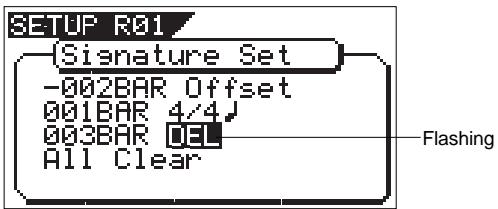
- Press the [ENTER/YES] key.
The selected measure/signature setting will be deleted.
- After deleting, press the [EXIT/NO] key (or [STOP] key) to exit from the SETUP mode.
You cannot register the "001BAR" of "001BAR 4/4".
Take care because this procedure wipes out the tempo setting as well as time signature setting.
Clearing All Time Signature/Tempo Data
Be careful because this procedure wipes out the tempo setting as well as time signature setting.
- Under the above "Confirmation display," select "All Clear" and press the [ENTER/YES] key.
A following display of "All Clear," "SURE ?" will flash. This indicates the standby mode for clearing all signature setting data and the tempo data.
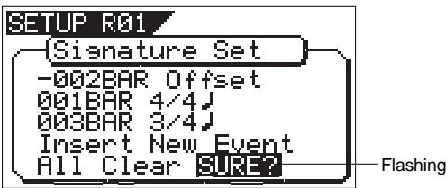
- Press the [ENTER/YES] key.
Except for the initial setting "001BAR 4 / 4 ,other time signature settings and the tempo setting will be cleared at the same time.
- Press the [EXIT/NO] key (or STOP key) to exit from the SETUP mode.
- Under the above "Confirmation display," select "-002BAR Offset" and press the [ENTER/YES] key.
The "002" display will change to flashing.
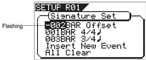
- Input the desired offset value with the [JOG] dial and press the [ENTER/YES] key.
Offset value can be input in the "-2" through "-9" range.
- After correction, press the [EXIT/NO] key (or [STOP] key) to exit from the SETUP mode.
The "Tempo Map Set" menu enables you to specify a tempo at a given point in a song that already has a time signature setting. For example, you can specify a tempo of 150 to the third beat of the 12th measure.
Time signature and tempo settings make a Tempo Map, which is used by the VF160EX to manage the song using the BAR/BEAT/CLK time base, and enable the metronome function. Tempo settings as well as time signature settings are required when you wish to output MIDI clock and Song Position Pointer to an external sequencer.
The tempo set figure setup here is an approximate figure and thus not accurate. Therefore, although the tempo map be matched with a personal computer, they will gradually drift apart. In order to prevent this drift, the personal computer side can be set to either MIDI clock sync or, the MIDI sync output signal temporarily set to "MIDI Clock" the figure reset to make it possible for the computer to read the accurate tempo, and the return it again to MTC sync.
- Initial Setting: 001BAR 1st beat 120 bpm
- Bar to register: Follows to the time signature setting
- Beat to register: Follows to the time signature setting
- Available tempo: 30 ~ 250, DEL (delete)
- Maximum setting points:64
- The setting is applicable song by song.
- The setting can be saved or loaded as a part of the song data
- The setting is memorized even when the power is off.
- Make sure you choose the right program before setting this mode.
1. Select a program for which to set a tempo setting.
2. Under the menu selection display, select "Tempo Set" and press the [ENTER/YES] key.
The display will change, confirming the current tempo setting. At the initial setting, the display will be as shown below, indicating that tempo of the first beat for the 001 bar is 120 and subsequent tempo is not setup.
"Insert New Event" should be selected at setup of a new tempo. When the [JOG] dial is rotated, the currently displayed items can be selected alternately.
![FOSTEX VF160EX - Under the menu selection display, select "Tempo Set" and press the [ENTER/YES] key. - 1](/content/2025/01/168450/images/04dec12112bafe59293be40851768382bb1ad13a2ffc172c5e2f4972341a6052.jpg)
New Registering of Tempo
1. Under the above "Confirmation display," select "Insert New Event" and press the [ENTER/YES] key.
The "Insert New Event" section will change to new tempo setup display and "002" will flash. The bar value thus displayed will be the last setup bar value +1 and tempo value will be identical with the last setting (Example: In the initial setup state, "002BAR 1 = 120" will be displayed.
![FOSTEX VF160EX - Under the above "Confirmation display," select "Insert New Event" and press the [ENTER/YES] key. - 1](/content/2025/01/168450/images/93b2898f3f5541b9a6fddb8621a234d8c9b9bfd9ab39015100282c25e715a05e.jpg)
The bar value that can be input is identical with the above "signature setup." When the [ENTER/YES] key is pressed, "beat value" will change to flashing.
The meter value that can be input is identical with the above "signature setup." When the [ENTER/YES] key is pressed, "tempo value" will change to flashing.
The tempo can be input within the range of 30 through 250. When the [ENTER/YES] key is pressed, the tempo map value thus input will be set and return to the above mentioned "Confirmation display for tempo map."
5. To register another tempo map, repeat steps 1 through 4.
6. Upon completing registering, press the [EXIT/NO] key (or [STOP] key) to exit from the SETUP mode.
For a setup example, if it is attempted to setup the following tempo in the music that is set to "001BAR 4 / 4 " and "005BAR 3 / 4 " by the previous "signature setup," as seen in the music score below, the tempo map must be set as follows.
![FOSTEX VF160EX - Upon completing registering, press the [EXIT/NO] key (or [STOP] key) to exit from the SETUP mode. - 1](/content/2025/01/168450/images/1e5d300e63c8a1c64946baed283f7263d2e30b8411b31d68804ada8667121f6f.jpg)
| Tempo Map |
| Time signature setting | Tempo setting |
| 001 BAR 4/4 | 001 BAR 1 ↓ ↓ = 120
003 BAR 1 ↓ ↓ = 90 |
| 005 BAR 3/4 | 005 BAR 3 ↓ ↓ = 60
007 BAR 2 ↓ ↓ = 120 |
Correction of the Registered Tempo
- Under the above "Confirmation display," select the tempo map which is to be changed and press the [ENTER/YES] key.
The same as before, "tempo value" will flash.
- Input the desired tempo with the [JOG] dial and press the [ENTER/YES] key.
- Upon completing registering, press the [EXIT/NO] key (or [STOP] key) to exit from the SETUP mode.
Erasing of the Registered Tempo
- Under the above "Confirmation display," select the tempo map which is to be erased and press the [ENTER/YES] key.
In the same way as before, tempo value will flash and "DEL" will be shown aside it.
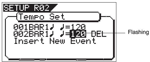
- Press the [F FWD] key and select "DEL," then press the [ENTER/YES] key.
The selected tempo map will be erased.
- Upon completing registering, press the [EXIT/NO] key (or [STOP] key) to exit from the SETUP mode.
You cannot register the "001BAR 1 = 120 .
Setting the Metronome function ["Click"]
"Setting the Metronome function" menu allows you to determine whether or not the VF160EX outputs a metronome sound from track 16 during playback or recording. Turning the Metronome function on enables you to record your performance while playing the instrument accompanying the metronome sound.
Metronome sound will be output from track 16.
For this reason, when the metronome function is activated, a new sound source cannot be recorded on the track to which the metronome sound is to be output or sound recorded on this track cannot be played back.
If the metronome function is not to be used, be sure to reset it to "Off."
- Initial Setting
: “Off”
- Available setting
: “Off” or “On”
- The setting is applicable song by song.
- The setting can be saved or loaded as a part of the song data
- The setting is memorized even when the power is off.
- Make sure you choose the right program before setting this mode.
1. Select "Click" in the menu selection display and press the [ENTER/YES] key.
The currently set item ("Off" or "On") will flash ("Off" will flash if in the initial state).
![FOSTEX VF160EX - Select "Click" in the menu selection display and press the [ENTER/YES] key. - 1](/content/2025/01/168450/images/bdebd9c7920933275f8e965334e0a3a54dc08337735fcf685726a6f9c3d14fef.jpg)
2. Select "On" or "Off" with the [JOG] dial and press the [ENTER/YES] key.
The selected item will be setup.
| On | Metronome sound will be output from track 16. |
| Off (default) | Metronome sound will not be output. |
- Press the [EXIT/NO] key (or [STOP] key) to exit from the SETUP mode.
Setting a preroll value ["Prameroll Time"]
The VF160EX features a Preroll function that enables you to locate a position a few seconds prior to a specified locate point. The "Setting a preroll value" menu enables you to set the preroll time (in seconds).
The Preroll function is convenient when you wish to monitor the audio data from a point slightly before the locate point.
- Initial setting:
"00" second
- Setting range of preroll time:
"00"- "10" seconds in one second steps
- You can set the value for each Program individually.
- The settings can be saved and loaded as part of the song data.
- The settings are maintained after you turn off the power to the VF160EX.
![FOSTEX VF160EX - Setting a preroll value ["Prameroll Time"] - 1](/content/2025/01/168450/images/26d9d15cf495614a2d4b4fe3426b06e10ad4860a7f18355356e30c48febed0fd.jpg)
- Select "Prewoll Time" in the menu selection display and press the [ENTER/YES] key.
The currently set preroll time will flash. "00" will flash in the initial setting.
![FOSTEX VF160EX - Setting a preroll value ["Prameroll Time"] - 2](/content/2025/01/168450/images/f6853ddecf1c833adaf00c4095b275a27bce1002592b44c0244be4e29f15c983.jpg)
- Input the desired preroll value with the [JOG] dial and press the [ENTER/YES] key.
The VF160EX will be set to the Preroll time thus input.
- Press the [EXIT/NO] key (or STOP key) to exit from the SETUP mode.
The preroll function is active when locating using the [LOCATE] key or in the auto return function. It is not active when locating using the combination of the [SHIFT] + [PREV] keys or the [SHIFT] + [NEXT] keys, or locating ABS O or REC END.
Setting MIDI sync output signal ["Midi Sync Out"]
The "Setting MIDI sync output signal" menu enables you to select the type of MIDI sync signals output from the MIDI OUT connector on the rear panel of the VF160EX to an external MIDI device.
The options are MIDI clock & Song Position Pointer, or MTC (MIDI time code). Select an appropriate option depending on the type of signal supported by the connected MIDI device.
If you select MIDI clock & Song Position Pointer, first you need to set the time signatures and tempo as described previously. If you select MTC, you first need to set the MTC frame rate, the MTC offset time, and the MTC offset mode as described later.
The currently set item will flash. "CLK" will flash in initial setting.
![FOSTEX VF160EX - Setting MIDI sync output signal ["Midi Sync Out"] - 1](/content/2025/01/168450/images/fe2fcee5db4b428a4425f8a29859153ec1681d2277e6ee942d62dc38b7a59f44.jpg)
- Select the desired MIDI sync signal with the [JOG] dial and press the [ENTER/YES] key.
| CLK (Initial setting) | MIDI clock and song position pointer will be output. |
| MTC | MIDI time code will be output. |
| Off | Any MIDI sync signal will not be output. |
- Press the [EXIT/NO] key (or STOP key) to exit from the SETUP mode.
Setting an MTC frame rate ["Frame Rate"]
The "Setting an MTC frame rate" menu enables you to set the frame rate for MTC output from the MIDI OUT connector of the VF160EX to an external MIDI device. If you have already set the type of MIDI sync output signal to "MTC", you need to set the frame rate. Use the frame rate of MTC received by the external MIDI device (or sequence software).
- Initial setting:
"25" (25 frames)
- Setting range of frame rate: “24”, “25”, “29df”, “29nd”, “30df” or “30nd”
- You can set the value for each Program individually.
- The settings can be saved and loaded as part of the song data.
- The settings are maintained after you turn off the power to the VF160EX.
1. Select "Frame Rate" in the menu selection display and press the [ENTER/YES] key.
The currently set frame rate will flashes. "25" will flash in the initial setting.
![FOSTEX VF160EX - Select "Frame Rate" in the menu selection display and press the [ENTER/YES] key. - 1](/content/2025/01/168450/images/45f941039cc3766ce263b87b1bb7dfd3a91a3dd8da3723fec7e566da5e522eb5.jpg)
2. Select the desired frame rate value with the [JOG] dial and press the [ENTER/YES] key.
It will be set to the selected frame rate.
3. Press the [EXIT/NO] key (or STOP key) to exit from the SETUP mode.
There are no 29.97nd or 29.97df in the MTC standard. Use either 30nd or 30df unless you definitely need to synchronize the VF160EX with NTSC video.
Setting an MTC offset value ["Mtc Offset Set"]
The "Setting an MTC offset value" menu enables you to specify an offset time value - the difference between the time of MTC output from the VF160EX and the ABS 00m 00s 00f 00sf time. You need to specify this value if you have selected "MTC" for the "Setting MIDI sync output signal" menu.
With the initial setting of 00h 59m 57s 00f 00sf, for example, MTC of 59m 57s 00f 00sf is output at the ABS time 00m 00s 00f 00sf. You can also set an offset value from the 001bar 1beat 00clk value (bar/beat) on the Tempo Map. Refer to the next section for information on MTC Offset mode.
For example, if you set MTC Offset mode to "ABS" (See the next section) and you wish to start the song from MTC's 01h 00m 00s 00f, you may wish to set a preroll of three seconds with an MTC offset of 00h 59m 57s 00f.
1. Select "Mtc Offset Set" in the menu selection display and press the [ENTER/YES] key.
It will change to the second level display of the "Mtc Offset" menu and the currently set offset value will be shown.
00h 59m 00f 00sf will be displayed in the initial state and "s" will flash. Flashing indicates the editable point.
![FOSTEX VF160EX - Select "Mtc Offset Set" in the menu selection display and press the [ENTER/YES] key. - 1](/content/2025/01/168450/images/ec4e5a6dc8721ad8a2b9defa656a61e372ca615f811e3121bbb0c5e85b1192c5.jpg)
Offset value thus input will be set.
Advancing or retarding the input figure is carried out automatically with reference to the currently set MTC frame rate figure.
3. Press the [EXIT/NO] key (or STOP key) to exit from the SETUP mode.
Setting MTC Offset mode ["Offset Mode"]
If you have selected "MTC" in the "Setting Offset mode" menu, you need to select MTC Offset mode.
This menu enables you to determine whether the specified MTC is output at ABS 00h 00m 00s 00f or at 001bar 1beat 00clk (bar/beat) of the Tempo Map.
- As an example, if you set MTC Offset mode to "ABS" and you wish to start the song from MTC's 1h 00m 00s 00f, you may want to set a preroll of three seconds with MTC offset of 00h 59m 57s 00f. If you select "BAR" as the MTC Offset mode, a preroll of two measures is automatically set. Use 01h 00m 00s 00f; do not set a preroll value.
-
If you set Offset mode to "BAR" and use MTC to synchronize sequence software on the computer, the tempo of the sequencer may sometimes slip gradually. This is because the tempo of the VF160EX and the tempo of the software are slightly different even if both use the same tempo. Some sequence software can read the tempo output from the VF160EX correctly. We recommend that you use the tempo of the VF160EX on the sequence software. No such problems will occur if the sequence software synchronizes the VF160EX via MIDI clock, instead of MTC.
-
Initial setting: "ABS"
- Offset mode option: "ABS" or "Bar"
- You can set the mode for each Program individually.
- The settings can be saved and loaded as part of the song data.
- The settings are maintained after you turn off the power to the VF160EX.
1. Select "Offset Mode" in the menu selection display and press the [ENTER/YES] key.
The currently set offset mode will flash. "ABS" will flash in the initial setting.
![FOSTEX VF160EX - Select "Offset Mode" in the menu selection display and press the [ENTER/YES] key. - 1](/content/2025/01/168450/images/7460e7deefd0adeda401dbb589d0b0c8040008fc9a3c7d7cc8e21ad43a98c108.jpg)
2. Select the desired offset mode with the [JOG] dial and press the [ENTER/YES] key.
The selected offset mode will be set.
| “ABS” (Initial setting) | The specified MTC offset time is output at ABS 00h 00m 00s 00f. |
| “BAR J” | The specified MTC offset time is output at 001bar 1beat 00clk of the Tempo Map. |
3. Press the [EXIT/NO] key (or STOP key) to exit from the SETUP mode.
Setting the Slave mode ["Slave Mode"]
This mode allows you to choose the VF160EX slave mode setting either On or Off.
If you set the slave mode to "On", the VF160EX will synchronize to the incoming MTC (MIDI Time Code) from master unit. It will also synchronize to a type of external sync signal which you have chosen with the section "Slave Type setting."
- Initial setting: "Off"
- Offset mode option: "On" or "Off"
- You can set the mode for each Program individually.
- The settings can be saved and loaded as part of the song data.
- The settings are maintained after you turn off the power to the VF160EX.
1. Select "Slave Mode" in the menu selection display and press the [ENTER/YES] key.
The currently set slave mode will flash. "Off" will flash in the initial setting.
![FOSTEX VF160EX - Select "Slave Mode" in the menu selection display and press the [ENTER/YES] key. - 1](/content/2025/01/168450/images/87ff4e9f02405da0a4e0fd72f5867b3bae149827aac956f1383c97560a09f661.jpg)
2. Select "On" or "Off" with the [JOG] dial and press the [ENTER/YES] key.
3. Press the [EXIT/NO] key (or STOP key) to exit from the SETUP mode.
Upon exit from the SETUP mode, the "SLV" (SLAVE) icon will flash.
This icon will change to constant lighting when VF160EX is correctly synchronized with the external equipment.
![FOSTEX VF160EX - Press the [EXIT/NO] key (or STOP key) to exit from the SETUP mode. - 1](/content/2025/01/168450/images/8db77c4b843b403d4cc536f17e22c876d095ff6a9d51d5ddff967405e55699d8.jpg)
Setting the Slave Type ["Slave Type"]
If you have set Slave Mode to "On" in the previous section "Slave Mode Setting," you can choose what type of external sync signal that the VF160EX synchronizes to. This mode allows you to choose the external sync signal type.
- Initial setting: "Vari"
- Offset mode option: "Vari", "Free", "SPDIF" or "adat"
- You can set the mode for each Program individually.
- The settings can be saved and loaded as part of the song data.
- The settings are maintained after you turn off the power to the VF160EX.
- You need to input MTC from an external device to the VF160EX with any Slave Type.
- The VF160EX re-chase window is fixed to ten frames. That is, if an offset between the master device and slave device exceeds ten frames, the VF160EX interprets that as out of sync, and tried to chase and lock to MTC sent from the master device. This operation is called "re-chasing." During the re-chase operation, audio output is muted. If the slave machine slips with MTC from the master device by less than ten frames, the slave machine continues running while recognizing the slippage.
- When you set the Slave Type, the Vari Pitch function is automatically disabled. (The "VARI PITCH" indicator turns off.)
1. Select "Slave Type" in the menu selection display and press the [ENTER/YES] key.
The currently set slave type will flash. "Vari" will flash in the initial setting.
![FOSTEX VF160EX - Select "Slave Type" in the menu selection display and press the [ENTER/YES] key. - 1](/content/2025/01/168450/images/f62bb0837a5d56c845bdfd50cd4deced45f847d9b2ca405b257a2dd9fc4f7b12.jpg)
2. Select the desired slave type with the [JOG] dial and press the [ENTER/YES] key.
It will be set to the selected slave type.
| Free | After chase lock is achieved, the VF160EX enters the free run mode with reference to the internal clock. If Digital In is selected, the VF160EX runs in sync with the clock derived from Digi-tal In. |
| Vari (Initial setting) | After chase lock is achieved, the VF160EX runs in the vari pitch mode to keep sync with the master. Note that if the Digital In is selected, the VF160EX runs in the same manner as "Free". |
| SPDIF | After chase lock is achieved, if the VF160EX receives an S/PDIF digital signal from the master, it runs in sync with the S/PDIF clock. Note that, if Digital In is selected, the VF160EX runs in sync with the clock derived from Digital In. |
| adat | After chase lock is achieved, if the VF160EX receives an adat digital signal from the master, it runs in sync with the adat clock. Note that, if Digital In is se-lected, the VF160EX runs in sync with the clock derived from Digital In. |
- Press the [EXIT/NO] key (or STOP key) to exit from the SETUP mode.
Setting the Record Protect function ["Rec Protect"]
The "Setting the Record Protect function" menu allows you to turn the Record Protection function On or Off. When this function in turned "On", you cannot record, paste, or erase data. Use this function to protect your important data from being accidentally erased.
- Initial setting:
"Off"
- Offset mode option:
"On" or "Off"
- You can set the mode for each Program individually.
- The settings can be saved and loaded as part of the song data.
- The settings are maintained after you turn off the power to the VF160EX.
1. Select "Rec Protect" in the menu selection display and then press the [ENTER/YES] key.
The presently set item (On or Off) will flash. "Off" will flash in the initial setting.
![FOSTEX VF160EX - Select "Rec Protect" in the menu selection display and then press the [ENTER/YES] key. - 1](/content/2025/01/168450/images/2d2e2bc506ef424e4bf51e6f40173256dc53e35e42945d6511171d16a3ee7dab.jpg)
2. Select "On" or "Off" with the [JOG] dial and then press the [ENTER/YES] key.
It will be set to the selected item ("On" or "Off").
Selecting "Off" enables recording; you can record, paste, and erase data.
Selecting "On" disables recording; and you cannot record, paste, or erase data.
3. Press the [EXIT/NO] key (or STOP key) to exit from the SETUP mode.
When recording is disabled ("On") and you try to record, paste, or erase data, the VF160EX displays "Protected!" for a second, indicating that you cannot perform the operation.
To perform the operation you need to enable recording ("Off").
In the [Setting digital input] menu, whether the signal assigned to tracks 1 through 16 are digital signals (adat digital signal/SP DIF digital signal) or analog signals, can be setup.
By using this function, it becomes possible to digitally record from external digital equipment (CD, MD, DAT, adat, digital mixer, etc.). If "S/P DIF" is selected for input of digital, the S/P DIF signal (L, R) applied to DIGITAL/ DATA INPUT of VF160EX, it will be assigned to any two tracks, and if "adat" is selected, the adat signals will be assigned to tracks 1 through 8. If it is set to "Analog", analog signals input to the mixer will be assigned to tracks 1 through 16.
If set to "S/P DIF or adat, "DIGITAL" will be lit in the display when the DIGITAL/DATA INPUT is locked.
Should "DIGITAL" blink, check the connecting cables between external equipment and recheck the setups of VF160EX and external equipment.
- Initial setting: "Analog"
- Options: "Analog", "adat", or
"SPDIF" (L = 1 16 R = 1 16)
- You can set the mode for each Program individually.
- The settings can be saved and loaded as part of the song data.
- The settings are maintained after you turn off the power to the VF160EX.
1. Select "Digital In" in the menu selection display and press the [ENTER/YES] key.
The items currently set will be shown in reversed white and black (In the initial state, "Analog" will be reversed in white and black).
![FOSTEX VF160EX - Select "Digital In" in the menu selection display and press the [ENTER/YES] key. - 1](/content/2025/01/168450/images/2ba47894ab5844b330bfa9eaa0034b1a72544b49e2055f86da80ac1a487f2ec8.jpg)
2. Select the desired "digital in" with the [JOG] dial.
Depending on the item selected, the following will be shown in the LCD.
![FOSTEX VF160EX - Select the desired "digital in" with the [JOG] dial. - 1](/content/2025/01/168450/images/21354cbd9996d75f178ac1cd58abfebc87d2e5232108870de326839f996b0f90.jpg)
When in the initial setup and selecting "SPDIF," simultaneous with indicating that L of the S/P DIF digital signal is assigned to track 1 and that R to track 2, "<-REW F FWD->" will also be shown.
This is indicating that any track can be selected for assigning to L/R. If the [REWIND] key or [F FWD] key is pressed, the blinking “L” or “R” will move.
If the [JOG] dial is rotated, numbers 1 through 16 can be input at the blinking point.
When selecting "SPDIF," because S/P DIF digital signals can be assigned to any two tracks within 1 through 16, simultaneous recording of S/P DIF digital signal + analog signal is possible by input of analog signals into the other tracks (Refer to "Chapter 5 Features Applications" for details).
![FOSTEX VF160EX - Select the desired "digital in" with the [JOG] dial. - 2](/content/2025/01/168450/images/88b25043b9ccac0238bcb69f367dc6b7bc6ff2859999f111bca7af500426e956.jpg)
- AT SELECTION OF "adat"
At selection of "adat," adat digital signals (1-8) only will be assigned to tracks 1-8 and analog signals can be input to tracks 9-16. As adat digital signals can be input to tracks 1-8 and analog signals into tracks 9-16 by using this feature, simultaneous recording of analog/digital 16 tracks can be realized. For details, refer to "Chapter 5 Features Applications."
3. Select the desired "digital in" and press the [ENTER/YES] key.
The selected "digital in" will be setup.
If you set the digital input to "SPDIF", and press the [ENTER/YES] key you will see a copyright warning. You can read the entire message by rotating the [JOG] dial. If you accept, press the [ENTER/YES] key again.
![FOSTEX VF160EX - Select the desired "digital in" and press the [ENTER/YES] key. - 1](/content/2025/01/168450/images/41d67d1d946cb21a0e977997eb9f7f6a83e3c43eb0e1c1d7b9b0f70ffacc46f6.jpg)
4. Press the [EXIT/NO] key (or STOP key) to exit from the SETUP mode.
When a correct digital signal (adat or S/P DIF) is input from the external digital equipment and then VF160EX is locked to the input signal, "ADAT" or "SPDIF" will be lit in the normal display as shown below.
If this display blinks, it indicating that an incorrect digital signal is input to the VF160EX. In such a case, check connections between any external equipment or the external equipment digital out setting.
![FOSTEX VF160EX - Press the [EXIT/NO] key (or STOP key) to exit from the SETUP mode. - 1](/content/2025/01/168450/images/20f1de104647e3abdfbd0e2d9c8f5ccd398739ae187268af0815b6bd9fac47b5.jpg)
At setting of "SPDIF"
![FOSTEX VF160EX - Press the [EXIT/NO] key (or STOP key) to exit from the SETUP mode. - 2](/content/2025/01/168450/images/a34e7f42466e2e32a78dbb55dd6321fac3d208f05272c51ef9175bf0ab8bb8d2.jpg)
At setting of "ADAT"
Setting Digital Output ["Digital Out"]
In the "Setup of digital output" menu, the type of digital signal to be output to external digital equipment from the VF160EX DIGITAL/DATA OUT connector, can be setup.
By using this feature, digital signals recorded in VF160 can be directly sent without conversion to external digital equipment (MD, DAT, adat, digital mixer).
When outputting digital signals to external digital equipment, the external digital equipment sampling frequency must be set identical to that of the VF160EX.
- Initial setting: "SPDIF"
- Options: "SPDIF" or "adat"
- You can set the mode for each Program individually.
- The settings can be saved and loaded as part of the song data.
- The settings are maintained after you turn off the power to the VF160EX.
1. Select "Digital Out" in the menu selection display and press the [ENTER/YES] key.
The current setting will flash. "SPDIF" will flash in the initial setting.
![FOSTEX VF160EX - Select "Digital Out" in the menu selection display and press the [ENTER/YES] key. - 1](/content/2025/01/168450/images/109053dadf1798495506b7b401f9f02d0ce82d5ef71f4aa6ebf0bf5cd994ba6e.jpg)
2. Select the desired "digital out" with the [JOG] dial.
Depending on the selected item, LCD will be as follows.
AT SELECTING OF "SPDIF" (initial setup)
When this setting is selected, STEREO BUSS L, R signals will be output as S/P DIF digital signals and should be selected at digital mixdown to a digital master recorder.
AT SELECTING OF "adat"
At selecting of "adat," signals from tracks 9-16 will be output as adat digital signals.
If signals from tracks 1-8 are to be output as adat digital signals, it must be executed after exchanging between tracks 1-8 and 9-16 by using the track exchange function (The same applies at output of data in the additional track).
3. Select the desired digital out and press the [ENTER/YES] key.
The selected digital out will be setup.
- Press the [EXIT/NO] key (or STOP key) to exit from the SETUP mode.
Setting BAR/BEAT Resolution mode ["Resolution"]
The "Setting BAR/BEAT resolution mode" menu enables you to turn BAR/BEAT resolution mode on and off.
The initial setting is "Off." When you turn this mode "On", the CLK (clock) digits will be always round off to "00" and be stored in the memory key while the VF160EX is using the BAR/BEAT/CLK time base.
That is, beat-resolution is used. Using this function allows you to automatically store a beat-resolution value of the CLIPBOARD IN/OUT points and other points in real-time. (Press the [STORE] key, then the corresponding memory key while playing the VF160EX.) Therefore, it is very convenient when you perform the Copy & Paste or Move & Paste operation in beat-resolution.
For example, assume that you have stored the value for 001bar 1/46 clk as the CLIPBOARD IN point, and the value for 002bar 4/51 clk as the CLIPBOARD OUT point. These values will be used as they are if BAR/BEAT resolution mode is turned off. However, the mode is turned on, the following values will be stored instead. The following example has a time signature setting of 4/4.
001 bar 1 J 46 clk -> 001 bar 1 J 00 clk
(A clk value of 46 will be rounded off.)
002 bar 4 J 51 clk->>003 bar 1 J 00 clk
(A clk value of 51 will be rounded up.)
- Initial setting: "Off"
- Options: "On" or "Off"
- You can set the mode for each Program individually.
- The settings can be saved and loaded as part of the song data.
- The settings are maintained after you turn off the power to the VF160EX.
1. Select "Resolution" in the menu selection display and press the [ENTER/YES] key.
The presently set item will be flash (On or Off).
"Off" will flash in the initial setup.
![FOSTEX VF160EX - Select "Resolution" in the menu selection display and press the [ENTER/YES] key. - 1](/content/2025/01/168450/images/5c47d5d0349f0f977ac82c46c00dcd091ea3efbab583723c06887eaa45f2450d.jpg)
2. Select "On" or "Off" with the [JOG] dial and press the [ENTER/YES] key.
- Press the [EXIT/NO] key (or STOP key) to exit from the SETUP mode.
Setting the MIDI device number ["Device ID"]
The "Setting the MIDI device number" menu enables you to set the VF160EX device ID number required to control the VF160EX from a sequence software using MMC (MIDI Machine Control).
The transmit device ID links to this setting. You can set the device ID from 00 to 99.
However, if the device ID number of the message the VF160EX receives is [7F], the VF160EX will recognize it to perform the corresponding operation, regardless of its device ID setting.
- Initial setting: “00”
- Options: “00” ~ “99”
- You can set the mode for each Program individually.
- The settings can be saved and loaded as part of the song data.
- The settings are maintained after you turn off the power to the VF160EX.
1. Select "Device ID" in the menu selection display and press the [ENTER/YES] key.
The presently device number will be flash.
"00" will flash in the initial setup.
![FOSTEX VF160EX - Select "Device ID" in the menu selection display and press the [ENTER/YES] key. - 1](/content/2025/01/168450/images/3a9dc7c4ec535ff243c47550fdd64f70230886f7c7fe2a7bfc5904e08b48eab7.jpg)
- Select desired device number with the [JOG] dial and press the [ENTER/YES] key.
- Press the [EXIT/NO] key (or STOP key) to exit from the SETUP mode.
Checking the number of track events ["Number Of Event"]
The "Checking the number of track events" menu enables you to check the number of events on each track. Each track (including Additional tracks) of VF160EX Programs consists of consecutive audio files (and "zero" files). The number of events represents the total number of audio files and 0 files. Each track can contain up to 512 events.
If you are editing a song of typical length (about six minutes), repeated editing operation does not usually exceed this maximum number. (Exceeding this limit is called "event number overflow.") Even a 20-minute song will not cause event number overflow. This is because the recorder system always optimizes the data structure by keeping the number of events low. However, if a recording on a track is scattered in different areas of the disk, or if you have made a very long recording on a single track and performed many edits, you should be wary of "event number overflow." To avoid this problem, use the "Checking the number of track events" menu to check the number of events on each track prior to recording or editing.
1. Select "Number of Event" in the menu a selection display and press the [ENTER/YES] key.
It will change to the "Event" second level and the event number currently in each track will be displayed (The
symbol indicates there is data below). *** is the event number.
![FOSTEX VF160EX - Select "Number of Event" in the menu a selection display and press the [ENTER/YES] key. - 1](/content/2025/01/168450/images/dbeacd158d65b9e0e1293fdfe9f52c08271be88c96593e78ff5dead160d78793.jpg)
- Use the [JOG] dial to select another (01~24) to check the number of events on the corresponding track.
- Press the [EXIT/NO] key (or [STOP] key) to exit from the SETUP mode.
Format information of the current drive currently installed can be checked by using the "Drive Format Information" menu. Should any trouble occur in the VF160EX, providing the information obtained here to our nearest Fostex Service Station will be of great help in giving quick service.
The following items will be displayed and can be confirmed.
- Manufacture / Model of the currently installed hard disk.
- Format method
- Format type
- Simultaneously recordable number of tracks
- Number of bits at formatting
- Sampling frequency at formatting
- Present number of programs
- Present number of free blocks
- Audio file / maximum number of events and its program No.
- Specific capacity of the drive
- Remaining capacity of the drive
-
Present software version
-
Select "Drive Information" in the menu selection display and press the [ENTER/YES] key.
It will change to the "Drive Information" second level and the current drive information currently in use will be displayed (The symbol indicates there is data below).
![FOSTEX VF160EX - The Drive Format Information ["Drive Information"] - 1](/content/2025/01/168450/images/57188e9c321f8a661b3377628f00ddd572d078a2d566e163383e2ad005e52a2e.jpg)
- As the [JOG] dial is rotated, information will be displayed one by one.
- Press the [EXIT/NO] key (or [STOP] key) to exit from the SETUP mode.
Fader Fix Mode Setting ["Fader Fix"]
Whether the fader manipulation should be reflected on the sound volume or not can be set.
The setup content will be held even if the main power is switched off.
The "Fader Fix Mode" can be made to function when set in other (CH, MST or CH & MST) than "Off" of the next item on the "Fader Recall Mode".
The currently set will flash. "Off" will flash in the initial setting.
![FOSTEX VF160EX - Fader Fix Mode Setting ["Fader Fix"] - 1](/content/2025/01/168450/images/d750db60b4f4c5a88326e3e8ddf2cb62e72b29dc78e55e25283defaadc489c3e.jpg)
- Select the desired item with the [JOG] dial and press the [ENTER/YES] key.
The selected item will be set.
| On | For all modes, manipulation of the Channel fader/Master fader will have not affect on the sound volume. Any accidental shifting of the fader position by vibration and misoperation can be prevented. |
| Off (Initial setting) | Manipulation of the Channel fader/ Master fader will affect the sound volume. |
- Press the [EXIT/NO] key (or [STOP] key) to exit from the SETUP mode.
Fader Recall Mode Setting ["Fader Recall"]
In the "Setup of the fader recall mode" menu, whether each channel input fader/master fader settings should be recalled or not at scene recall, can be setup.
When changing the setting from any option other than "Off" to "Off", or from "CH&MST" to "MST" or "CH", "Level Adjust! Sure?" appears in the display (this is because, after a scene is recalled, the physical fader positions may not match the levels). Press the [ENTER/YES] key and adjust levels. Note that there may be sudden level jumps depending on the fader positions. If you do not adjust levels, press the [EXIT/NO] key.
- Initial setting: "Off"
- Options: "Off", "CH", "MST" or "CH & MST"
- You can set the value for each Program individually.
- The settings can be saved and loaded as part of the song data.
- The settings are maintained after you turn off the power to the VF160EX.
1. Select "Fader Recall" in the menu a selection display and press the [ENTER/YES] key.
The currently set will flash. "Off" will flash in the initial setting.
![FOSTEX VF160EX - Select "Fader Recall" in the menu a selection display and press the [ENTER/YES] key. - 1](/content/2025/01/168450/images/b9d9be3b51d2c9c34666f095929f9ad3d0ef852b376a703de240639c8d7b49f0.jpg)
The selected item will be set.
| Off (Initial setting) | When scene is recalled, the fader position immediately prior to recalling the scene will be directly employed without recalling the setup figures of each channel fader and the master fader. |
| CH (Channel) | When scene is recalled, setup figures of each channel faders only will be recalled and not recall the master fader setup figure. |
| MST (Master) | When scene is recalled, the setup figure of the master fader only is recalled and the channel fader setup figures will not be recalled. |
| CH & MST | When scene is recalled, each channel faders and the master fader set up figures will both be recalled. |
- Press the [EXIT/NO] key (or [STOP] key) to exit from the SETUP mode.
Pair Fader setting [Pair Fader Set]
The "Pair Fader Set" menu sets whether or not you simultaneously control the adjacent odd and even channels.
Normally, each channel fader on the VF160EX acts independently. By setting "Pair Fader Set" to "On", you can pair faders of two adjacent channels, allowing the odd channel fader to control the partner (even) channel's level. This function is useful for stereo source, etc.
You can also control "Pair Fader channels" simultaneously during channel parameter editing, etc. See below.
- Initial setting: "Off" for all pair channels
- Options: "On", "Off" for each pair channels
- You can set the value for each Program individually.
- The settings can be saved and loaded as part of the song data.
- The settings are maintained after you turn off the power to the VF160EX.
1. Select "Pair Fader Set" in the menu selection display and press the [ENTER/YES] key.
The pair fader set status (on or off) list is shown, where the channel 1 & 2 line is highlighted. In the initial condition, all paired channels are set to "Off".
![FOSTEX VF160EX - Select "Pair Fader Set" in the menu selection display and press the [ENTER/YES] key. - 1](/content/2025/01/168450/images/5d6c11ce9a4a63848d2eaa005180819ea5bfe1f270db413f107a40b7cc622d1b.jpg)
2. Select the desired paired channels via the [JOG] dial, and press the [ENTER/YES] key.
The setting field ("On" or "Off" is shown) for the selected channels flashes.
3. Select "On" or "Off via the [JOG] dial, and press the [ENTER/YES] key.
The setting is completed and the display returns to highlight a single line, as shown in step 1 above.
4. To set another pair, repeat steps 2 and 3.
5. After completing all settings, press the [EXIT/NO] key (or the [STOP] key) to exit the SETUP mode.
If you control the even channel fader which is paired, the following message appears.
Controlling the paired even channel fader does not affect the level.
![FOSTEX VF160EX - After completing all settings, press the [EXIT/NO] key (or the [STOP] key) to exit the SETUP mode. - 1](/content/2025/01/168450/images/67a61d163ed2aca80e52e40b7385ab8af1a1b6627e39264610b3ac96fcddaf21.jpg)
For paired fader channels, besides fader control, the following functions are controlled simultaneously.
- Effect send level adjustment
By pressing either of the [CH STATUS/CH SEL] keys for paired channels, the icons for both channels start flashing, and you can control the effect send levels for both channels simultaneously using the [JOG] dial.
- Effect send pre/post setting
By pressing either of the [CH STATUS/CH SEL] keys for paired channels, the icons for both channels start flashing, and you can set pre or post for the effect sends of both channels simultaneously using the [JOG] dial.
- Aux send level adjustment
By pressing either of the [CH STATUS/CH SEL] keys for paired channels, the icons for both channels start flashing, and you can control the Aux send levels for both channels simultaneously using the [JOG] dial.
- Aux send pre/post setting
By pressing either of the [CH STATUS/CH SEL] keys for paired channels, the icons for both channels start flashing, and you can set pre or post for the Aux sends of both channels simultaneously using the [JOG] dial.
EQ (HI/MID/LO) adjustment
By pressing either of the [CH STATUS/CH SEL] keys for paired channels, the icons for both channels start flashing, and you can adjust EQ for both channels simultaneously.
- On/off of SOLO
By pressing either of the [CH STATUS/CH SEL] keys for paired channels, you can select on or off of solo monitor for both channels simultaneously.
- On/off of channel mute
By pressing either of the [CH STATUS/CH SEL] keys for paired channels, you can select on or off of mute for both channels simultaneously.
By pressing either of the [CH STATUS/CH SEL] keys for paired channels, you can select the input sources for both channels simultaneously.
- Setting of REC source for BUSS recording
By pressing either of the [CH STATUS/CH SEL] keys for paired channels, you can select the REC sources for both channels simultaneously.
- Setting of the built-in compressor
By pressing either of the [CH STATUS/CH SEL] keys for paired channels (channels 13-14 or 15-16), you can set the compressor parameters for both channels simultaneously.
On/Off of phantom power setting ["Phantom Power"]
ON/OFF of phantom power provided at INPUT 7 and 8 (XLR-3-31) can be setup.
Do the following before using the phantom power:
- When connecting a condenser microphone to MIC INPUT 7 and 8 (XLR-3-31 type) of the VF160EX, be sure this microphone requires phantom power (+48V).
- Switch ON the phantom power after connecting the condenser microphone.
- Always mute the VF160EX output when switching ON-OFF the phantom power and when connecting or disconnecting the microphone cable from the VF160EX.
- Always switch OFF the phantom power when connecting a dynamic microphone to INPUT 7 and 8 (XLR-3-31 type). Otherwise, a malfunction could occur.
Phantom power cannot be used with the following equipment:
- Unbalanced output microphones.
- High impedance microphones.
- In a microphone where there is voltage leak between pin 2/pin 3 and pin 1 of the microphone cable canon connector.
- Old model ribbon microphones of the ground center tap output type.
If the phantom power supply is switched ON, do not connect an unbalanced line dynamic type microphone to INPUT 7 or INPUT 8. Be extremely careful of this as this could damage the internal microphone amplifier of VF160EX.
- Initial setting: "Off"
- Options: "On" or "Off"
- You can set the value for each Program individually.
- The settings cannot be saved and loaded as part of the song data.
- The settings are maintained after you turn off the power to the VF160EX.
1. Select "Phantom Power" in the menu selection display and press the [ENTER/YES] key.
The currently set will flash. "Off" will flash in the initial setting.
![FOSTEX VF160EX - Select "Phantom Power" in the menu selection display and press the [ENTER/YES] key. - 1](/content/2025/01/168450/images/9fa40808d03d195f2cb30df0e254466b7dacd4b8a1d564afe932cccfb0028693.jpg)
2. Select the desired item with the [JOG] dial and press the [ENTER/YES] key.
The selected item will be set.
| Off (Initial setting) | Phantom power will not be supplied. |
| On | Phantom power is supplied to INPUT 7 and 8. The PHANTOM LED will be lit. |
3. Press the [EXIT/NO] key (or [STOP] key) to exit from the SETUP mode.
Compressor Channel Setting ["Comp. Channel"]
In the "Setup of the compressor channel" menu, the channel in which the VF160EX internal compressor function should be activated can be setup. The compressor can be made to function in channels 13-14 or 15-16.
Regardless to this setting, the compressor can be applied at all times to the master channel.
The VF160EX internal compressor can be made to function only in the channel setup here and the master channel. However, editing of EQ in channels other than the master channel, is not permissible.
- Initial setting: "Off"
- Options: "Off", "13-14" or "15-16"
- You can set the mode for each program individually.
- The settings can be saved and loaded as part of the song data.
- Although the setup content will not be held at switch off of power, it can be saved as a scene memory.
1. Select "Comp. Channel" in the menu selection display and press the [ENTER/YES] key.
The currently set will flash. "Off" will flash in the initial setting.
![FOSTEX VF160EX - Select "Comp. Channel" in the menu selection display and press the [ENTER/YES] key. - 1](/content/2025/01/168450/images/6dfb61fe902deb55239ab32eab63f406dffdec7488482fab86d36099688a294e.jpg)
2. Select the desired comp. Channel with the [JOG] dial and press the [ENTER/YES] key.
The selected item will be set.
| Off (Initial setting) | Compressor can be applied only in the master channel. |
| 13-14 | The compressor can be applied to channels 13/14 and the master channel. |
| 15-16 | The compressor can be applied to channels 15/16 and the master channel. |
3. Press the [EXIT/NO] key (or [STOP] key) to exit from the SETUP mode.
EQ cannot be applied to the channel (Except the master channel) setup for the compressor.
With the compressor channel setup, if the EQ editing mode is entered, this condition will be indicated by the [CH STATUS/CH SEL] key LED.
The channel in which the LED (green) is blinking is an indication that EQ editing is possible in this channel and the channel in which the LED is not lit is an indication that EQ cannot be applied to this channel.
If a channel that cannot be EQ editing had been selected, the "Can't Select!" message will blink to warn that the operation is ineffective.
The schematic below is an example of channels 15-16 setup as the compressor channel.
![FOSTEX VF160EX - Press the [EXIT/NO] key (or [STOP] key) to exit from the SETUP mode. - 1](/content/2025/01/168450/images/143b8809257e67d7d358ca55b7c393ff69e5adb88a194c8243c882fc46757adc.jpg)
This is indicating that channels 15 and 16 are setup as the compressor channel.
Trouble Shooting
A breakdown? If you suspect so, please read the following explanations before requesting repairs.
Troubles at Recording?
Level meter does not light up even though recording track is set and channel fader/master fader is raised to the "0" position.
Press the [RECORD] key only. The key will blink in red and the READY track will be in the input monitor mode. The recorder output can be applied to each channel faders. The level meter is unable to function unless the READY track is changed to the input monitor mode. For details, read pages 32-33 and 45-46.


* Level does not increase even though the channel fader is raised?
Recording level will not increase although the READY track channel fader is raised to maximum (+6).
Adjust [TRIM] knob to a suitable level.
The level cannot be raised for small input signals if the [TRIM] knob is positioned at "LINE" (full CCW).
Rotate the [TRIM] knob to just before the sound distorts.
![FOSTEX VF160EX - Adjust [TRIM] knob to a suitable level. - 1](/content/2025/01/168450/images/bc8f4dd2459c332890683703a162f458aea9493a42791149c37b880b56a3a96e.jpg)
Although the READY track is set to input monitor, no sound is heard in the headphone although the meter is indicating the level.
Raise the [PHONES] knob.
No sound will be heard if the headphones adjuster is turned down. Also, if monitoring with an external monitor speaker, raise the [MON OUT] knob.
![FOSTEX VF160EX - Raise the [PHONES] knob. - 1](/content/2025/01/168450/images/1784b2e44e9078653ab469fc74cc6e5e7a9438b3d94e5193cdbf14c3212361c0.jpg)
![FOSTEX VF160EX - Raise the [PHONES] knob. - 2](/content/2025/01/168450/images/2e580cda26f9e04f313ff19109b568da382da4b80145c4a58668e4e964e17d71.jpg)
- When attempting to select a recording track for DIRECT recording, are there some tracks between 9-16 that cannot be selected?
DIRECT recording is executed, basically, with all channels in the "TRK" mode at setup of [INPUT]-[TRACK], as shown below. Should any one channel of 9-16 is set to "INPUT", that channel cannot be set as a recording track at DIRECT recording.
![FOSTEX VF160EX - Could there be some channels set to "INPUT" at setup of [INPUT]-[TRACK] ? - 1](/content/2025/01/168450/images/c9847af837b54f4d8eded8dc423809dbc8bfe0538b5dbfe5f6feefab6b1712ce.jpg)
Sound adjusted by EQ cannot be recorded by DIRECT recording?
When DIRECT recording, EQ cannot be applied.
Application of EQ at recording is permissible only at BUSS recording. Although EQ can be applied to the input signal at DIRECT recording, this is strictly listening to the monitor sound only and the original sound will be recorded without alteration.
However, when BUSS recording, EQ can be applied to each input signal and recorded.
- Effect sound cannot be recorded at BUSS recording?
Select source channel for the effect.
When BUSS recording, in order to record while applying effect to the source channel, effect 1 or effect 2 must be selected together with selecting the source channel as shown in the schematic below. In the example below, input H and effect 1 are selected for the source channel. For details, read page 45.
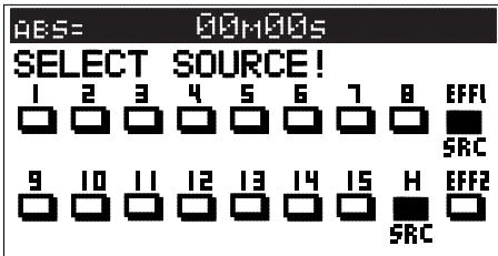
- Even though effect is selected for the sourc channel, effect cannot be applied?

Raise the effect send level.
Initially, the effect send level of each channel will all be at "0".
Select the channel for applying effect and raise the effect send level with the [JOG] dial. For details, read page 52.
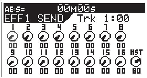
- Ping pong recording cannot be executed?
Is the playback track for ping pong set to source channel.
Press the [BUSS-SOURCE] key and set the track for ping pong to source channel.
Then, press the [BUSS-RECTRK] key and set the ping pong objective track in the READY mode.
In the example below, tracks 1-4 and 9-12 are selected for the source channel and their signals sent for ping pong into tracks 15 and 16.
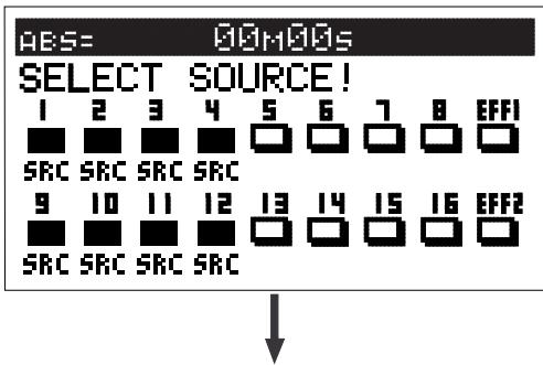
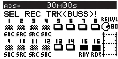
- Cannot record external digital signals?
Match "Digital In" in the SETUP mode to the digital signal (S/P DIF or adat) to be input.
Read page 141 for details.
- Cannot record analog signals?
Could the track about to be recorded still be set for digital inputs.
Analog signals cannot be recorded in a track set for digital input by "Digital In" in the SETUP mode. Reset the digital input to "Analog."
- At playback of digital signals just recorded, sound pitch is not normal?
Record digital signals of sampling frequency identical to that of the VF160EX.
The VF160EX sampling frequency is 44.1kHz / 16 bit. In a sampling frequency other than 44.1kHz / 16 bit, it will be recorded with the wrong pitch. Time count will also be incorrect.
Having trouble Editing?
- A warning message appears although it was only execution of copy-clip (or move-clip)?
Correctly register the CLIPBOARD IN and OUT points.
The relation between CLIPBOARD IN point and OUT point is "IN point<OUT point".
If it is registered in reverse relationship, copy-clip (or move-clip) cannot be executed.
- When copy paste (or move paste) is executed, the sound section located before head of the bar is missing?
Use the ALIGN SEL function.
If the "ALIGN SEL" function is used at executing copy paste (or move paste), the sound section located in front of the bar head can be included at pasting.
Refer to page 74 for details.
MIDI Implementation Chart
(Digital Multitracker)
Model VF160EX
Date:
Version: V1.00
MIDI Implementation Chart
| Function.................................................. | Transmitted | Recognized | Remarks |
| Basic Channel | Default | X | X | |
| Changed | X | X | |
| Mode | Default | X | X | |
| Message | X | X | |
| Altered | ********** | X | |
| Note Number: | True Voice | X | X | |
| ********** | X | |
| Velocity | Note ON | X | X | |
| Note OFF | X | X | |
| After Touch | Key's Channel's | X | X | |
| X | X | |
| Pitch Bend | X | X | |
| Control Change | X | X | |
| Program Change | True # | X | X | |
| ********** | X | |
| X | X | |
| System Exclusive | ○(rem. 1) | ○(rem. 2) | |
| Common | : Quarter Frame | ○ | ○ | |
| : Song Position | ○ | X | |
| : Song Select | X | X | |
| : Tune | X | X | |
| System Real Time | : Clock | ○ | X | |
| : Commands | ○(rem. 3) | X | |
| Aux. Message | : Local ON/OFF | X | X | |
| : All Notes OFF | X | X | |
| : Active Sense | X | X | |
| : Reset | X | X | |
| Notes | rem.1: MMC (Device ID=00~99, 127), MTC, Identity reply rem.2: MMC (Device ID=00~99, 127), MTC, Inquiry rem.3: START, STOP, CONTINUE |
Mode 1: OMNI ON, POLY Mode 2: OMNI ON, MONO
Mode 3: OMNI OFF, POLY Mode 4: OMNI OFF, MONO
:Yes
X: No
MMC Command List
| Command list | Movement (Recorder) |
| 01: STOP | STOP |
| 02: PLAY | PLAY |
| 03: DEFERRED PLAY | DEFERRED PLAY |
| 04: FAST FORWARD | F FWD |
| 05: REWIND | REWIND |
| 06: RECORD STROBE | REC |
| 07: RECORD EXIT | PUNCH OUT |
| 09: PAUSE | STOP |
| 40: WRITE | Refer to MMC Response/Information Field List |
| 41: MASKED WRITE | Refer to MMC Response/Information Field List |
| 42: READ | Refer to MMC Response/Information Field List |
| 44: LOCATE | LOCATE to Setting Data |
| 46: SEARCH | CUE/REVIEW (+/- 1~60 times) |
| 47: SHUTTLE | CUE/REVIEW (+/- 1~60 times) |
| 4C: MOVE | Refer to MMC Response/Information Field List |
| 4D: ADD | Refer to MMC Response/Information Field List |
| 4E: SUBTRACT | Refer to MMC Response/Information Field List |
| MMC Response/Information Field List | Command |
| 01: SELECTED TIME CODE | READ/WRITE/MOVE/ADD/SUBTRACT |
| 03: REQUESTED OFFSET | READ/WRITE |
| 04: ACTUAL OFFSET | READ |
| 08: GP 0 | READ/WRITE/MOVE/ADD/SUBTRACT |
| 09: GP 1 | READ/WRITE/MOVE/ADD/SUBTRACT |
| 0A: GP 2 | READ/WRITE/MOVE/ADD/SUBTRACT |
| 0B: GP 3 | READ/WRITE/MOVE/ADD/SUBTRACT |
| 0C: GP 4 | READ/WRITE/MOVE/ADD/SUBTRACT |
| 0D: GP 5 | READ/WRITE/MOVE/ADD/SUBTRACT |
| 0E: GP 6 | READ/WRITE/MOVE/ADD/SUBTRACT |
| 0F: GP 7 | READ/WRITE/MOVE/ADD/SUBTRACT |
| 48: MOTION CONTROL TALLY | READ |
| 4C: RECORD MODE | READ/WRITE |
| 4E: TRACK RECORD STATUS | READ |
| 4F: TRACK RECORD READY | READ/WRITE/MASKED WRITE |
| 51: RECORD MONITOR | READ/WRITE |
Inquiry Message List
| IDENTITY REQUEST: F0, 7E, <channel>, 06, 01, F7
IDENTITY REPLY: F0, 7E, <channel>, 06, 02, 51, 01, 00, 13, 04, **, **, **, **, F7 |
| 51 :Fostex ID |
| 01, 00 :Device family code |
| 13, 04 :Device family number VF160EX |
| **, **, **, ** :Software version |
Maintenance
Cleaning the exterior
- For normal cleaning, use a soft dry cloth.
For stubborn dirt, moisten a cloth in diluted detergent, wring it out firmly, and wipe the dirt off. Then polish with a dry cloth. Never use solvents such as alcohol, thinner or benzene, since these will damage the printing and finish of the exterior.
Specifications
Recording/Reproducing
| Recording Medium | : 3.5 inch, hard disk (E-IDE type) |
| Recording Format | : FDMS-3 (*) |
| Save/Load Format | : FDIO-1 (**) |
| Sampling Frequency | : 44.1kHz |
| Quantization | : 16-bit linear (Non expanded) |
| A/D Converter | : 20-bit 64 times, over sampling, Delta-Sigma |
| D/A Converter | : 24-bit 128 times, over sampling, Delta-Sigma |
| No. of Recording Track | : 16 real tracks + 8 additional tracks |
| *16 tracks for simultaneous recording |
| Vari Pitch Control | : +/- 6% |
| Crossfade | : 10msec. |
| Recording/Reproducing Frequency | : 20Hz ~ 20kHz |
Input 1 ~ 6
Connector : 06mm Phone jack (Unbalanced)
Input Impedance : 50k or more (Unbalanced)
Standard Input Level -50dBV 2dBV
Input 7 and 8
Connector : 06mm Phone jack (Unbalanced)
XLR-3-31 type (Balanced)
Input Impedance : 50k or more (Unbalanced), 10k or more (Balanced)
Standard Input Level -50dBV 2dBV
Phantom Power (XLR only) +48VDC (Setting of ON/OFF with SETUP mode)
Output (Tip)
Load Impedance
Input Level
Connector
Output (Tip)
Load Impedance
Input Level
Input (Ring)
Load Impedance
Output Level
MONITOR Output
Connector
Load Impedance
Output Level
HEADPHONE
Connector
Load Impedance
Output Level
AUX SEND 1 and 2
Connector
Load Impedance
| Output Level | : -10dBV |
| STEREO OUT L, R | |
| Connector | : RCA pin jack |
| Load Impedance | : 10kΩ or more |
| Output Level | : -10dBV |
| DIGITAL IN | |
| Connector | : Optical |
| Format | : (1) IEC 60958 (S/P DIF), (2) Alesis Proprietary Multi Channel Optical Interface (Either (1) or (2) is selected in the SETUP mode) |
| DIGITAL OUT | |
| Connector | : Optical |
| Format | : (1) IEC 60958 (S/P DIF), (2) Alesis Proprietary Multi Channel Optical Interface (Either (1) or (2) is selected in the SETUP mode) |
| MIDI IN/OUT | |
| Connector | : DIN 5 PIN |
| PUNCH IN/OUT | |
| Connector | : Ø6mm Phone jack (An optional FOOT SW Model 8051 can be connected.) |
| General | |
| Dimensions | : 402 (W) x 110 (H) x 370 (D) mm |
| Weight | : Approx. 6.1kg |
| Power Supply | : 120VAC 60Hz, 230V~ 50/60Hz (AC inlet type) |
| Power Consumption | : 22W |
Accessories
Operation Manual
:Power Cable
- Fostex Disk Management System-3
** Fostex Data In Out-1
Specifications and appearance are subject to change without notice for product improvement.
"Adat" an the adal® symbol are trademarks of Alesis Corporation.
Block Diagram
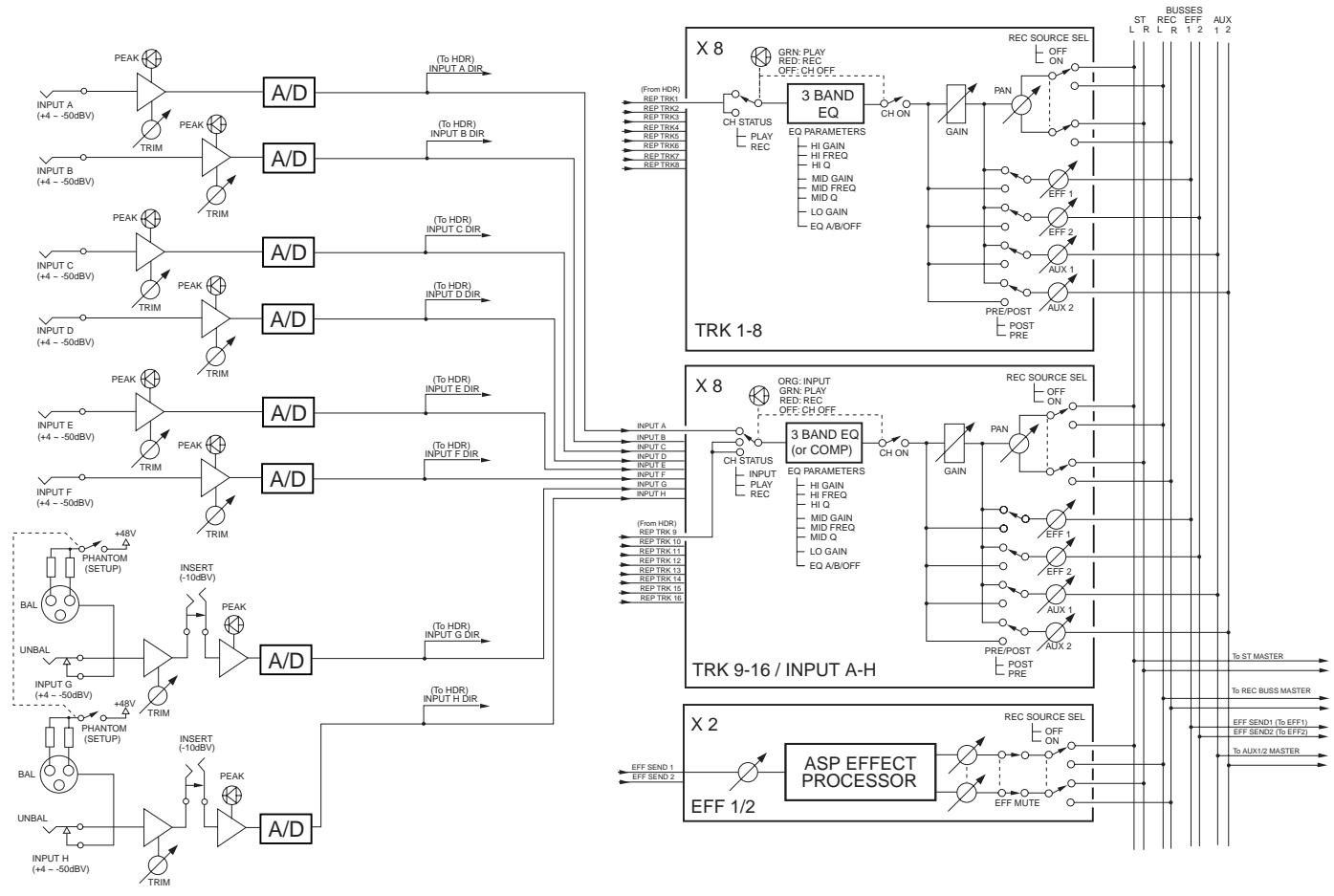
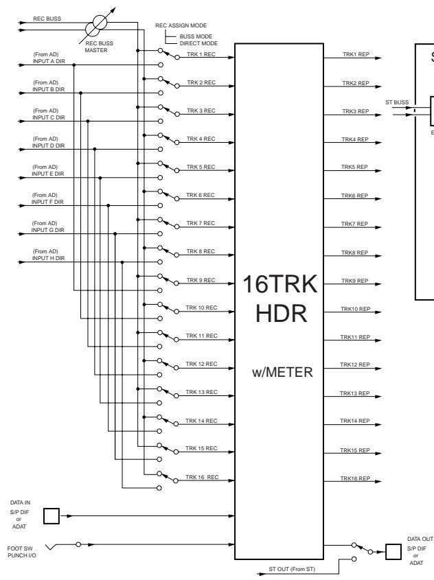
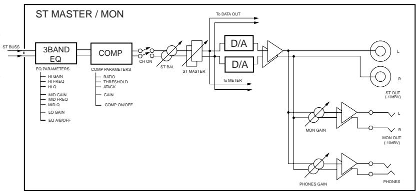
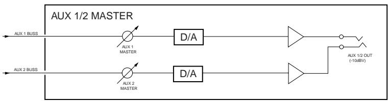
Declaration of EC Directive
This equipment is compatible with the EMC Directive (89/336/EEC) - Directive on approximation of member nation's ordinance concerning the electromagnetic compatibility and with the Low Voltage Directive (73/23/EEC)
- Directive on approximation of member nation's ordinance concerning electric equipment designed to be used within the specified voltage range.
The Affect of Immunity on This Equipment
The affect of the European Specification EN61000-6-1 (coexistence of electromagnetic waves - common immunity specification) on this equipment are as shown below.
- In the electrical fast transient/burst requirements, surge, conducted disturbances by radio-frequency fields, power frequency magnetic field, radiate electromagnetic field requirements and static electricity discharging environment, this could be affected by generation of noise in some cases.
FOSTEX DISTRIBUTORS LIST IN EUROPE
- Including non-EU countries.(as of October, 2003)
NAME: ATEC Audio-u. Videogeraete VertriebsgesmbH.
ADD: P. O. Box 22, FIN-02631 Espoo, Finland
TEL: (+358) 9-5259330, FAX: (+358) 9-52593352
NAME: Sennheiser France
ADD: 128 bis, avenue Jean-Jaures, 94851 Ivry-sur-Seine
Cedex, France
TEL: (+33) 149870300,FAX: (+33) 149870324
NAME: Mega Audio GmbH
ADD: Stromberger Str. 32, D-55411 Bingen, Germany
TEL: (+49) 6721-94330, FAX: (+49) 6721-32046
NAME: Bon Studio S. A.
ADD: 6 Zaimi Street, Exarchia, 106.83 Athens, Greece
TEL: (+30) 210-3809-605, 606, 607, 608
FAX: (+30) 210-3845-755, 210-3827-868
NAME: I. D. elrf. electronic Ltd.
ADD: ARMULA 38 108 REYKJAVIK, ICELAND
TEL: (+354) 588 5010, FAX: (+354) 588 5011
NAME: Proel S.p.A.
ADD: Zona Via Alla Ruenia, 37/43 64027-Sant'Omero
(Teramo), Italy
TEL: (+39) 0861-81241, FAX: (+39) 0861-887862
NAME: IEMKE ROOS AUDIO B. V.
ADD: Kuiperbergweg 20, 1101 AG Amsterdam, The
Netherlands
TEL: (+31) 20-697-2121, FAX: (+31) 20-697-4201
NAME: Fitzpatrick
ADD: P. B. 4316 Nydalen, 0402 Oslo, Norway
TEL: (+47) 23400380,FAX: (+47) 23400389
NAME: Caius - Tecnologias Audio e Musica, Lda.
ADD: Praca do Bom Successo, No 61 Bom Successo Trade
Center, Escritorio 701/702, 4150-1460 Porto, Portugal
TEL: (+351) 22-608-06-10, FAX: (+351) 22-608-06-29
NAME: Letusa S. A.
ADD: C/Laguna 10, 28923 Alcorcon, Madrid, Spain
TEL: (+34) 91-4862800, FAX: (+34) 91-6414597
NAME: TTS Scandinavia AB
ADD: Kavallerivagen 24, 172 48 Sundbyberg, Sweden
TEL: (+46) 8-59798000, FAX: (+46) 8-59798001
NAME: Audio Bauer Pro AG
ADD: Bernerstrasse-Nord 182, CH-8064 Zurich, Switzerland
TEL: (+41) 1-4323230, FAX: (+41) 1-4326558
NAME: SCV London
ADD: 40 Chigwell Lane, Oakwood Hill Industrial Estate,
Loughton, Essex IG10 3NY U.K.
TEL: (+44) 20-8418-0778, FAX: (+44) 20-8418-0624