
CBM-1000II - Watch CITIZEN - Free user manual and instructions
Find the device manual for free CBM-1000II CITIZEN in PDF.
| Product type | Line thermal printer |
| Brand | CITIZEN |
| Model | CBM-1000II |
| Printing method | Line dot thermal |
| Print width | 72 mm (576 dots) or 54 mm (432 dots) with 58 mm paper |
| Dot density | 8 × 8 dots/mm (203 dpi) |
| Print speed | 150 mm/s (1200 dot lines/s) |
| Number of columns | Font A: 48/42 columns (80 mm/58 mm), Font B: 64/56 columns |
| Interface | Serial (RS-232C) and Parallel (IEEE 1284 bidirectional) |
| Power supply | Type S: AC 120/230 V ±10%; Type A/D: DC 24 V ±7% |
| Power consumption | Approx. 100 W |
| Weight | Type S: approx. 2.0 kg; Type A/D: approx. 1.4 kg |
| Dimensions (W × D × H) | Type S: 145 × 190 × 157 mm; Type A/D: 145 × 190 × 114 mm |
| Paper | Thermal roll 80 mm or 58 mm wide, max Ø 83 mm |
| Main functions | Barcode printing, logos, auto cutter, cash drawer, 4 KB buffer |
| Maintenance and cleaning | Clean the thermal head with a cotton swab soaked in ethyl alcohol; clean the case with a soft dry cloth |
| Safety | Do not touch the head after printing (hot); unplug before maintenance; avoid liquids and foreign objects |
| Spare parts and repairability | Contact CITIZEN SYSTEMS dealer for maintenance and after-sales service |
| General information | Manual available in multiple languages; warranty not covered in case of misuse |
Frequently Asked Questions - CBM-1000II CITIZEN
User questions about CBM-1000II CITIZEN
0 question about this device. Answer the ones you know or ask your own.
Ask a new question about this device
Download the instructions for your Watch in PDF format for free! Find your manual CBM-1000II - CITIZEN and take your electronic device back in hand. On this page are published all the documents necessary for the use of your device. CBM-1000II by CITIZEN.
USER MANUAL CBM-1000II CITIZEN
LINE THERMAL PRINTER
MODEL CBM1000 TYPE II
User's Manual
Mode d'emploi
Benutzerhandbuch
Manuale dell'utente
Manual de Usuario
natural_image
Line drawing of a rectangular electronic device with ports and buttons (no text or symbols)If you want to dispose this product, do not mix with general household waste. There is a separate collection systems for used electronics products in accordance with legislation under the WEEE Directive (Directive 2002/96/EC) and is effective only within European Union.
Ge
natural_image
Symbol of a trash bin crossed out by two diagonal lines (no text or numbers present)
Declaration of Conformity
This printer conforms to the following Standards:
Low Voltage Directive 73/23/EEC, 93/68/EEC and the EMC Directive 89/336/EEC, 92/31/EEC, 93/68/EEC.
LVD : EN60950
EMC : EN55022 Class A
EN61000-3-2
EN61000-3-3
EN55024
This declaration is applied only for 230V model.
WARNING : This is a Class A product. In a domestic environment this product may cause radio interference in which case the user may be required to take adequate measures.
IMPORTANT: This equipment generates, uses, and can radiate radio frequency energy and if not installed and used in accordance with the instruction manual, may cause interference to radio communications. It has been tested and found to comply with the limits for a Class A computing device pursuant to Subpart J of Part 15 of FCC Rules, which are designed to provide reasonable protection against such interference when operated in a commercial environment. Operation of this equipment in a residential area is likely to cause interference, in which case the user at his own expense will be required to take whatever measures may be necessary to correct the interference.
CAUTION: Use shielded cable for this equipment.
Sicherheitshinweis
This digital apparatus does not exceed the class A limits for radio noise emissions from digital apparatus, as set out in the radio interference regulations of the Canadian department of communications.
1.1 Features ...... 9
1.2 Unpacking....9
2. BASIC SPECIFICATIONS .... 10
2.1 Model Classification .... 10
2.2 Outer Appearance and Component Parts 10
2.3 Basic Specifications 11
2.4 Print Paper Specifications and Print Position 12
2.5 Sensor Position and Cutter Position 13
3. OPERATION 14
3.1 Connecting the AC Adapter and AC Power Cord 14
3.2 Connecting Interface Cables 14
3.3 Connecting the Drawer Kick-Out Connector 15
3.4 Setting/Replacing Paper Rolls 16
3.5 Adjusting the Paper Near-End Sensor 16
3.6 Using 58 mm Wide Paper Rolls....17
3.7 Removing Jammed Paper 17
3.8 Cleaning the Print Head 17
3.9 Operation Panel and Error Indication 18
3.10 Self-printing....20
3.11 Hexadecimal Dump 20
3.12 Printer Buffer 21
3.13 Device ID 21
4. SETTING DIP SWITCHES 22
4.1 Location of DIP Switches 22
4.2 Table for Setting DIP Switches 22
5. MAINTENANCE AND SERVICE 24
APPENDIX 1. OUTLINE DRAWING ...... i
APPENDIX 2. BLOCK DIAGRAM ....i
APPENDIX 3. IDENTIFICATION OF SEND STATUS ...... ii
APPENDIX 4. PARALLEL INTERFACE ....iii
APPENDIX 5. SERIAL INTERFACE ...... v
APPENDIX 6. CONTROL COMMAND ...... vii
GENERAL PRECAUTIONS
1 The information contained herein is subject to change without prior notice.
2 All rights reserved. Reproduction of part or all of this document is prohibited without written permission from CITIZEN SYSTEMS.
3 Except explained elsewhere in this manual, do not attempt to service, disassemble or repair this product by yourself.
4 Note that CITIZEN SYSTEMS shall not be responsible for any damage attributable to incorrect operation/handling or improper operating environments which are not specified in this manual.
5 Operate this printer only as described in this manual. Failure to do so may cause accidents or other problems.
6 Data are basically for temporary use, not stored for a long period or permanently. Please note that CITIZEN SYSTEMS is not responsible for any damage or lost profit resulting from the loss of data caused by accidents, repairs, tests, or any other occurrence.
7 If you have any question or comment regarding the information contained in this manual, please contact your CITIZEN SYSTEMS dealer.
8 Please note CITIZEN SYSTEMS is not responsible for anything that may occur from operating this printer regardless of what is stated in "7" above.
SAFETY PRECAUTIONS
Before using this product for the first time, carefully read these SAFETY PRECAUTIONS. Incorrect operation may result in unexpected accidents (fire, shock, or injury).
● After having read this Manual, keep it in a safe, readily-accessible place for future reference.
- Some of the descriptions contained in this manual may not be relevant to some printer models.
In order to prevent injury hazard to operators, third parties or damage to property, special warning symbols are used in this user's manual to indicate important items to be strictly observed.
- The following describes the degree of hazard and damage that could occur if the printer is improperly operated by ignoring the instructions indicated by the warning symbols.

WARNING
Neglecting precautions indicated by this symbol may result in fatal or serious injury.

CAUTION
Neglecting precautions indicated by this symbol may result in injury or damage to properties.

This symbol is used to alert your attention to important items.

This symbol is used to indicate prohibited actions.

This symbol is used to alert you to the danger of electric shock or electrostatic damage.

This symbol denotes a request to unplug the printer from the wall outlet.
Caution Labels
ONLY USED FOR CONTROLLING THE DRAWER.
- Do not attempt to insert any plug (e.g. modular plug) other than the specified drawer kick-out connector plug into the drawer kick-out connector as it may damage the telephone connection or the printer.


CAUTION
- The thermal head remains at a dangerously high temperature immediately after use. Do not touch the head until it cools off.

WARNING
Do not use or store this product in a place where it will be exposed to:
- Flames or moist air
- Direct sunlight
• Hot airflow or radiation from a heating device
• Ill-ventilated atmosphere
• Chemical reactions in a laboratory
• Airborne oil, steel particles, or dust - Salty air or corrosive gases
• Static electricity or strong magnetic fields
● Neglecting these warnings may result in printer failure, overheating, emission of smoke, fire, or electric shock.


Do not drop any foreign object nor spill liquid into the printer. Do not place any object on the printer either.
- Do not drop any metallic object such as a paper clip, pin or screw into the printer.
- Do not place a flower base, pot or cup containing water on the printer.
- Do not spill coffee, soft drinks or any other liquid into the printer.
- Do not spray insecticide or any other chemical liquid over the printer.
● A metallic foreign object, if accidentally dropped into the printer, may cause printer failure, fire, or electric shock. Should it occur, immediately turn the printer off, unplug it from the supply outlet, and call your local CITIZEN SYSTEMS dealer.


Please observe the following precautions for power source and power cord:
- Do not plug or unplug the power cord with a wet hand.
- Use the printer only at the specified supply voltage and frequency.
- Use only the specified AC adapter with the printer.
- Check to make sure that the supply outlet from which the printer is powered has a sufficient capacity.
- Do not plug the power cord into a supply outlet with dust or debris left on its plug.
- Do not supply the printer from a power strip or current tap shared with other appliances.
- Do not use a deformed or damaged power cord.
● Neglecting to handle properly may result in printer failure, emission of smoke, fire, or electric shock.
● An overload may cause the power cable to overheat or the circuit breaker to trip.
- Do not allow anything to rest on the power cord. Do not place the printer where the power cord will be trampled on.
- Do not attempt to modify the power cord unnecessarily.
- Do not use or carry the printer with its power cord bent, twisted, or pulled.
- Do not lay the power cord in the neighbor of a heating device.
● Neglecting these cautions may cause wires or insulation to break, which could result in leakage, electric shock, or printer failure. If a power cord sustains damage contact your CITIZEN SYSTEMS dealer.
- Supply power to the printer from a convenient wall outlet, readily accessible in an emergency.
- Do not leave things around the supply outlet to always ensure easy access to it.
● The printer may not be immediately shut down in an emergency.
- Insert the power plug fully into the outlet.
- If the printer is not to be used for a long time period, leave it disconnected from its supply outlet.


Do not handle the printer in the following ways:
- Do not allow the printer to sustain strong impacts or hard jolts (e.g. trampling, dropping, striking with a hard edge).
- Never attempt to disassemble or modify the printer.
- Do not clean the printer with any organic solvent, such as alcohol, paint thinner, trichloroethylene, benzene, or keton.
● Neglecting to handle properly may result in printer failure, overheating, emission of smoke, fire, or electric shock.
Install, use, or store the printer out of the reach of children.
● The plastic bag the printer came in must be disposed of properly or kept away from children. Wearing it over the head may lead to suffocation.
● Electric appliances could cause an unexpected injury or accident if they are handled or used improperly.
- Keep the power cord and signal cables out of the reach of children. Also children should not be allowed to gain access to any internal part of the printer.

CAUTION
Place the printer on a flat surface.
● Otherwise it may drop off from its position.
Be careful where you place the printer and what is placed near it.
- Take care that a nearby wall or some kind of cloth does not block printer ventilation holes.
- Do not use the printer with any object placed on it.
- Be careful about internal heat buildup, which could cause fire and deform the case.
- Avoid using the printer near a radio or TV set or from supplying it from the same outlet as these appliances.
- For interconnections, use shielded or a twisted pair of cables and ferrite cores, or other anti-noise devices.
- Avoid using the printer with a device that is a strong source of noise.
● The printer may have an adverse effect on nearby radio or TV transmissions. There may also be cases when nearby electrical appliances adversely influence the printer, causing data errors or malfunction.


Use the printer with its grounding post connected to a convenient grounding facility.
● If leakage occurs electric shock may result.
Do not connect the printer's grounding post to any of the following facilities:
- Utility gas piping
● A gas explosion could result
- Telephone line ground
- Lightning rod
- If lightening strikes a large surge of current may cause fire or shock
- Utility water pipes
● Plastic water pipes should not be used for grounding. (Those approved by a Waterworks Department may be used.)
Before connecting or disconnecting the grounding lead to or from the printer, always unplug it from supply outlet.


Before connecting or disconnecting the power cord or interconnect cables to or from the printer, always turn the entire system power off.
When disconnecting a cable, do not pull out by the cable. Always hold the plug.
Firmly insert the cable plug into its mating socket.
- A cross connection may damage the printer's internal electronics or the host system's hardware.
Only use the printer with devices that have designated solenoid specifications for the drawer kick-out connector.
● Neglecting this caution may result in malfunction or failure.


To prevent possible malfunction or failure observe the following:
- Avoid operating the printer without roll paper properly loaded or with paper not complying with specifications.
● May damage thermal head or result in poor print quality.
- Avoid using torn pieces of paper or spliced with plastic adhesive tapes.
- Avoid forcibly pulling already loaded paper by hand.
- Avoid wedging the paper in by the printer cover.
● May jam paper. To release, refer to “Removing Jammed Paper” in this manual.
- Avoid using a sharp pointed device to operate panel keys.
● Neglecting these cautions may result in printer malfunction or failure.


To prevent injury and printer failures from worsening, observe the following:
- In case of trouble do not attempt to repair the printer. Leave it to our service engineer.
- Do not touch the printing surface of the thermal head.
- Be careful that the printer cover does not entrap your hands or fingers.
- Be careful with sharp edges on the printer. Don't allow them to injure you or damage property.
- Do not touch any of the moving parts (e.g. paper cutter, gears, active electrical parts) while the printer is working.
● May result in electric shock, burn, or injury.
- If the printer emits smoke, an odd smell, or unusual noise while printing, immediately abort the current print session and unplug the printer from the supply outlet.


DAILY MAINTENANCE
Observe the following precautions for daily maintenance:
- When cleaning the printer, always turn it off and unplug it from the supply outlet.
- Use a soft, dry cloth for cleaning the surface of the printer case.
- For severe stains, use a soft cloth slightly dampened with water.
- Never use organic cleaning solvent such as alcohol, paint thinner, or benzen.
- Never use a chemically processed cleaning cloth.
• To remove paper chips, use a soft brush. - When transporting the printer, remove the roll paper from its paper holder.
- When cleaning the thermal head surface, use a cotton gauze slightly dampened with alcohol.


CAUTION
- Do not touch the thermal head's printing surface with bare hand or a metallic implement.
- The thermal head is at a dangerously high temperature immediately after printing. Allow it to cool off before launching maintenance work.
1. GENERAL OUTLINE
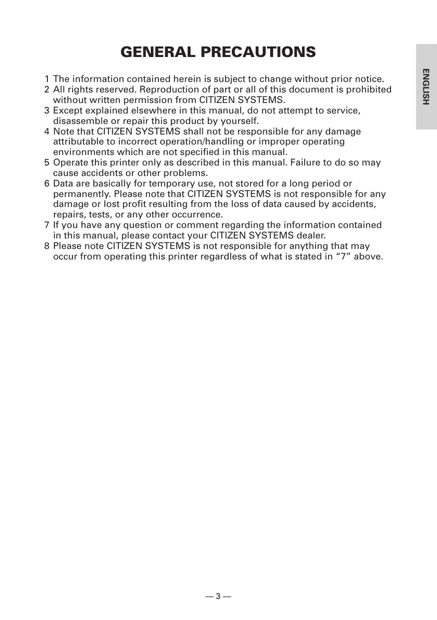
The CBM1000 Type II is a compact thermal line printer designed for use with a broad array of terminal equipment including data, POS, and kitchen terminals.
With extensive features, it can be used in a wide range of applications.
To obtain the best results from the CBM 1000 Type II printer, please read the instructions this manual thoroughly.
1.1 Features
● Paper drop-in mechanism. Supply/replace paper rolls by simply dropping a paper roll into the printer and closing the cover. Greatly facilitates paper handling and head cleaning.
● Ease of paper threading and head cleaning.
● High speed (150 mm/s), and low-noise thermal printing.
● Front-side paper ejection method. Allows printer installation and use anywhere with few restrictions.
● Hermetic covering structure. Protects foreign matter or liquid from entering the printer.
● Built-in input buffer.
- Barcode Printing. Made possible using special commands.
● Page mode. Now you can arrange pages freely.
● Registration of user-defined characters and logos into flash memory.
● Built-in drawer kick-out interface.
● Auto cutter mechanism provided as a standard unit.
- Two types of power supply. Select between an easy-to-handle, built-in power supply type and lightweight flat AC adapter type.
● Can use 58 mm wide paper rolls by employing the supplied partition.
1.2 Unpacking
When unpacking the printer, confirm that the following are provided:
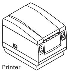
natural_image
Line drawing of a printer with no text or symbols on the device itself
Sample paper roll
AC adapter
(provided with the A type only)

User's manual
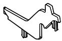
Partition
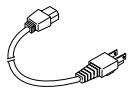
AC power cord
(not supplied with Type D)

CAUTION
- Do not use the printer in an environment where condensation can occur. If condensation forms, leave the power off until it completely evaporates.
2. BASIC SPECIFICATIONS
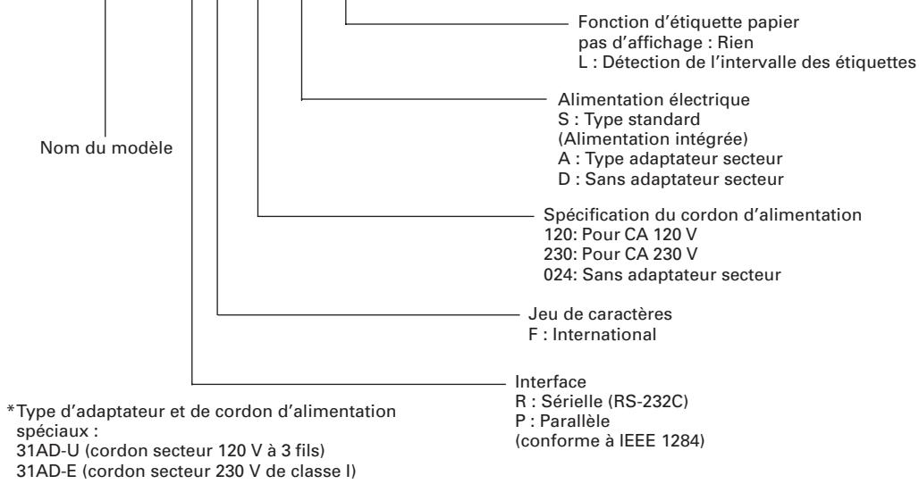
2.1 Model Classification
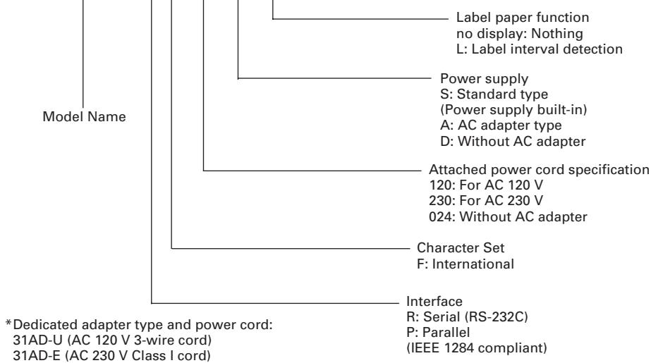
The printer models are classified by the following designation method:
CBM1000 II R F 120 S - L
flowchart
graph TD
    A["Model Name"] --> B["Label paper function no display: Nothing"]
    A --> C["L: Label interval detection"]
    A --> D["Power supply S: Standard type (Power supply built-in)"]
    A --> E["A: AC adapter type"]
    A --> F["D: Without AC adapter"]
    A --> G["Attached power cord specification 120: For AC 120 V"]
    A --> H["230: For AC 230 V"]
    A --> I["024: Without AC adapter"]
    A --> J["Character Set F: International"]
    A --> K["Interface R: Serial (RS-232C)"]
    K --> L["*Dedicated adapter type and power cord: 31AD-U (AC 120 V 3-wire cord)"]
    K --> M["P: Parallel (IEEE 1284 compliant)"]
    A --> N["31AD-E (AC 230 V Class I cord)"]
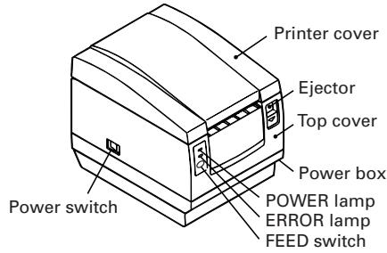
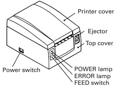
2.2 Outer Appearance and Component Parts
CBM1000II S
CBM1000II A/CBM1000II D
Drawer kick-out connector Grounding terminal
Drawer kick-out connector Grounding terminal
2.3 Basic Specifications
| ModelItem | CBM1000II RF120S/ACBM1000II PF120S/A | CBM1000II RF230S/ACBM1000II PF230S/A | CBM1000II RF024DCBM1000II PF024D |
| Print method | Line thermal dot print method | ||
| Print width | 72 mm/576 dots, (54 mm/432 dots)* ^1 | ||
| Dot density | 8 × 8 dots/mm (203 dpi) | ||
| Print speed | 150 mm/sec (Fastest, print density standard level), (1,200 dot lines/sec) | ||
| Number of print columns* ^2 | Font A: 48/42 (36/30)* ^1 columns (12 × 24)Font B: 64/56 (48/40)* ^1 columns (9 × 24) | ||
| Character size | Font A: 1.25 × 3.00 mm; Font B: 0.88 × 3.00 mm | ||
| Character type code page | Alphanumeric characters, International characters, Code pages PC437,Katakana, PC850, PC860, PC863, PC865, PC852, PC866, PC857, and Windows code page | ||
| Logo registration/print | Capable of registering user-defined characters and logos into flash memory. | ||
| Types of bar code | UPC-A/E, JAN (EAN) 13/8 columns, ITF CODE 39, CODE 128, CODABAR,CODE 93 | ||
| Line spacingPaper roll | 4.23 mm (1/6 inches), selectable using commandsThermal paper roll: 80 mm (58 mm) × ø 83 mmThermal Label paper roll : 80 mm (58 mm) × ø 83 mm(See “ Print Paper Specifications”.) | ||
| Label detection | Selects the L-Spec. (factory option) | ||
| Interfacing | Serial (RS-232C), Parallel (IEEE1284 compliant, Bi-directional communication) | ||
| Input buffer | 4K bytes (72 bytes selectable with a DIP switch) | ||
| Supply voltage | S type: AC 120/230 V ±10%; A type/D type: DC 24 V ±7% | ||
| Power consumption | Approx. 100 W | ||
| AC adapter specification | Rated input: AC 120 to 240 V, 50/60 Hz, 120 VARated output: DC 24 V, 1.9 A (Peak 3.5A) | — | |
| 31 AD-U | 31 AD-E | — | |
| Weight | S type: Approx. 2.0 Kg; A type/D type: Approx. 1.4 Kg | ||
| Outside dimensions | S type: 145 (W) × 190 (D) × 157 (H) mmA type/D type: 145 (W) × 190 (D) × 114 (H) mm | ||
| Operating temperature and humidity | 5 to 40°C, 35 to 85% RH (No condensation) | ||
| Storage temperature and humidity | -20 to 60°C, 10 to 90% RH (No condensation) | ||
| Reliability | Print head life: Pulse resistance 1 × 10^8 pulses (Print ratio 12.5%)Wear resistance 100 Km (At normal temperature/humidity with recommended paper used)Auto cutter life: 1,000,000 times of cutting (At normal temperature/humidity with recommended paper used) | ||
| Safety Standard* ^3 | UL, C-UL, FCC Class A | TÜV, GS, CE marking | UL, C-UL, FCC Class A,TÜV, GS, CE marking |
*1 Represents the value when a 58 mm wide paper roll is used (User selectable).
*2 The number of printable columns is selectable with a DIP switch.
*3 Represents the safety standards acquired when CITIZEN SYSTEMS-made adapters (31AD series) are used.
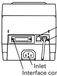
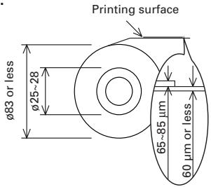
2.4 Print Paper Specifications and Print Position
(1) Thermal Paper roll
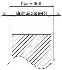
Unit: mm
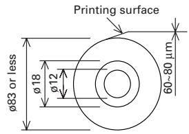
(Recommended papers) TF50KS-E2D from Nippon Paper KP50 from Shin-Ohji Paper F230AA or HP220A from Mitsubishi Paper or equivalent
(2) Thermal label sheet (label gap detection) * Only L-Spec.
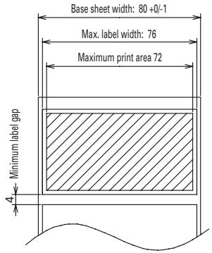
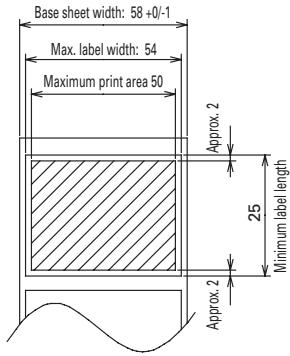
Unit: mm
(Recommended papers) KPT86S/G63BC P22 from Ohji Tac. or equivalent

CAUTION
- A roll paper not complying with the specifications may cause some departure in print tone. Adjust print tone with the DIP switch (see "Setting DIP Switches").
- Do not paste paper end to the core as it may cause coloration or faint letters if printed documents are exposed to a particular chemical or oil afterwards.
- Rubbing the document surface with your nail or metallic device may cause coloration.
- Coloration occurs at a temperature of around 70^ or above. Keep documents away from heat, moisture, or light.
2.5 Sensor Position and Cutter Position
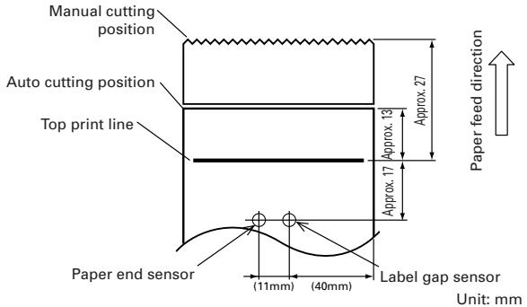

CAUTION
- Observe the following rules on the auto cutter usage:
- Every cut paper should be no less than 10 mm in length. Thin paper strips can cause paper to jam.
- When cutting a label roll, be sure to cut the base sheet. Never cut labels (tags).
3. OPERATION
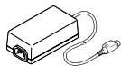
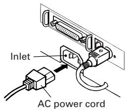
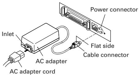
3.1 Connecting the AC Adapter and AC Power Cord
1 Turn off the power of the printer.
2 For the AC adapter type only: With the flat side of the AC adapter's cable connector facing upward, insert the cable connector into the power connector on the back side of the printer.
3 Connect the AC power cord to the inlet of the printer, and insert the AC power-cord plug into a suitable wall outlet.
Standard type
AC adapter type
Power connector pin configuration
| No. | Function |
| 1 | +24 |
| 2 | GND |
| 3 | N.C |
| SHELL | F.G |
 | |
Connector used:
TCS7960-53-2010 (Hosiden) or equivalent
Applicable connector:
TCP8927-63-1100 (Hosiden) or equivalent
TCP8927-53-1100 (Hosiden) or equivalent
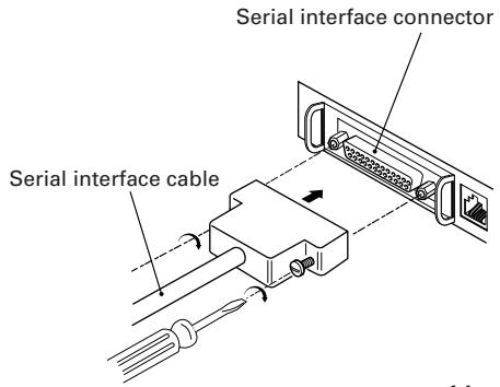
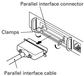
3.2 Connecting Interface Cables
1 Turn off the power of the printer. (As well as the connected host computer.)
2 Orient the interface cable terminal correctly and insert it into the interface connector.
3 Secure the cable terminal as shown below.
Serial interface cable: Fasten the connector with screws.
Parallel interface cable: Hold the connector with clamps.
4 Connect the other end of the interface cable to the host computer.
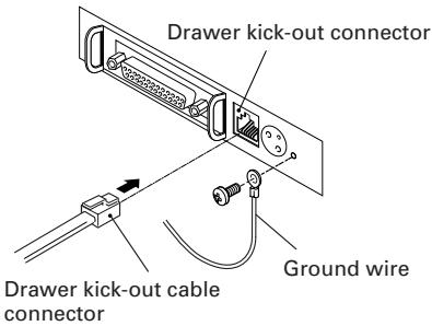
3.3 Connecting the Drawer Kick-Out Connector
1 Turn off the power of the printer.
2 Orient the drawer kick-out cable connector correctly, insert it into the drawer kick-out connector on the back of the printer.
3 Fasten the ground wire to the ground connector on the printer with a screw.

CAUTION
- Do not connect any other device than the specified drawer (Solenoid) to the drawer kick-out connector. (Do not connect a telephone line either.)
(1) Connector Pin Configuration
| No. | Signal | Function | 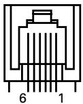 |
| 1 | FG | Frame Ground | |
| 2 | DRAWER 1 | Drawer 1 drive signal | |
| 3 | DRSW | Drawer switch input | |
| 4 | VDR | Drawer drive power supply | |
| 5 | DRAWER 2 | Drawer 2 drive signal | |
| 6 | GND | Common ground on circuits |
Connector used: TM5RJ3-66 (Hirose) or equivalent Applicable connector: TM3P-66P (Hirose) or equivalent
(2) Electrical characteristics
1) Driving voltage: 24 VDC
2) Driving current: Approx. 1 A max. (shall not exceed 510 ms.)
3) DRSW signal: Signal levels: "L" = 0 to 0.5 V, "H" = 3 to 5 V
(3) DRSW signal
DRSW signal status can be tested with the DLE+EOT, GS+a, or GS+r command or at pin 34 on the parallel interface port.
(4) Drive Circuit
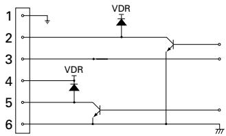

CAUTION
- No output is produced while printing.
- The drawers 1 and 2 cannot be driven simultaneously.
- A solenoid used for the drawer should be of 24 or more. The output current should be kept at 1 A or less; otherwise, breakdown or burning could occur.
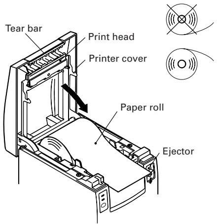
3.4 Setting/Replacing Paper Rolls
1 Turn on the printer.
2 Push the ejector in the direction shown to unlock the printer cover.
3 Placing your hands on both sides of the printer cover, open it until it comes to a stop.
4 Check the winding direction of the paper roll, and then place it into the paper roll holder correctly.
5 With the end of the paper approx. 5 cm out of the case of the printer, close the printer cover. Push lightly on the printer cover until a "click" is heard.
6 Remove an excess length of paper with the tear bar. (Manual cutter)

CAUTION
• Always use the specified types of paper roll.
- Use of other types of paper roll may not be able to guarantee the specified print quality or service life of the printer.
- When opening the printer cover, do not apply an excess force to it beyond its stop position.
- The print head becomes hot immediately after printing. Do not touch it with your hand. During printing, do not open the printer cover. Do not hold the end of the paper as it prints and ejects. Doing so may cause the paper to jam.
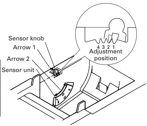
3.5 Adjusting the Paper Near-End Sensor
1 Open the printer cover.
2 Push the sensor knob in the direction of arrow 1 to disengage its claw (Or unlock the sensor unit), and then adjust the sensor unit to a desired paper remaining position within the range shown by arrow 2.
3 The following table shows the relationship between adjustment positions and levels of paper roll remaining. (A rough guide)
| Adjustment position | Level of paper remaining(Paper roll outside diameter/mm) |
| 1 | 18 |
| 2 | 21 |
| 3 | 24 |
| 4 | 27 |
* When specified paper rolls are used.

CAUTION
- Use the level of paper remaining (Paper-roll outside diameter) just as a guide as it varies depending on the particular printer and paper rolls used.
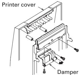
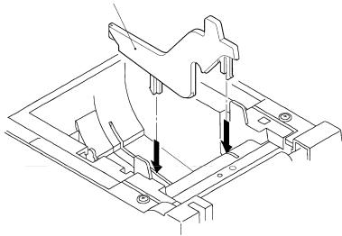
3.6 Using 58 mm Wide Paper Rolls
1 Turn off the power of the printer.
2 Open the printer cover.
3 Take off two screws and remove printer cover.
4 Take off damper retention screws, reposition damper (11 mm) in the direction of the arrow, then secure it with the original screws again.
5 Replace printer cover on printer.
6 Install the supplied partition into the position as illustrated.
7 Change DIP switch setting for 58 mm roll paper, by referring to "SETTING DIP SWITCHES".

CAUTION
- Do not change DIP switch setting from 58 mm into 80 mm roll paper in the middle of printing.
Partition
natural_image
Technical line drawing of a mechanical assembly with mounting brackets and a central component (no text or symbols)3.7 Removing Jammed Paper
1 Turn off the power of the printer.
2 Open the printer cover.
3 Remove the paper jam including any paper chips remaining. (Also take out the paper roll from the holder.)
4 Close the printer cover.
5 Turn on the printer. The auto cutter mechanism is initialized and the alarm is cleared.

CAUTION
- The print head becomes hot immediately after printing. Do not touch it with your hand. Do not touch the heating element of the head with a bare hand or metal object either.
3.8 Cleaning the Print Head
1 Open the printer cover.
2 Wipe off stains, such as dust and the like, on the heating element of the head using a cotton swab soaked in ethyl alcohol.

CAUTION
- The print head becomes hot immediately after printing. Do not touch it with your hand. Do not touch the heating element of the head with a bare hand or metal object either.
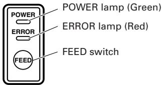
3.9 Operation Panel and Error Indication
1 POWER lamp (Green)
Lights when the power is turned on. It blinks when a memory check error has occurred.
2 ERROR lamp (Red)
Lights or blinks to show different error states. It also blinks while the printer is waiting for a macro to be executed.
3 FEED switch
Pressing this switch briefly causes one line of paper feeding.
While a macro is waiting to be executed, pressing the switch causes the macro to be executed.
4 Buzzer
A buzzer sound alerts the operator to an error.
| Error indication | POWER lamp | ERROR lamp | Buzzer | Recovery method |
| Memory Check error | Quick blinking | Lights | — | Not recoverable |
| Cover open | Lights | Lights | [IMAGE] (Four short beeps) × 2 | Close the cover. |
| Head overheat | Lights | Slow blinking | — | Recovers automatically when the temperature returns to normal. |
| Paper near-end | Lights | Lights | — | Set a new paper roll. |
| Paper end | Lights | Lights | [IMAGE] (Four short beeps) × 2 | Set a new paper roll. |
| Cutter motor lock | Lights | Quick and slow blinking | Three long beeps | Remove paper jams. |
| Macro execution wait | Lights | Slow blinking | — | Press the FEED switch. |
| Low voltage error | Lights | [IMAGE] | — | Not recoverable |
| High voltage error | Lights | Quick and slow blinking | — | Not recoverable |
| Waiting for label cutter action | Off | [IMAGE] | — | Press the FEED switch. |
| Waiting for label discharge | Off | Slow blinking | — | Remove label from peeler. |
| Label detection error | Off | Slow blinking | Three long beeps | Set the specified label roll. |
Description of errors
Memory Check error:
This error occurs if a memory read-after-write check or FROM sum check has resulted in an error (unrecoverable error).
Cover open:
When you open the printer cover, the cover open sensor is activated, causing the ERROR lamp to light and the printing operation to stop. (Not recoverable error)
Head overheat:
To protect the print head from overheating, the head temperature sensor is activated if the head temperature rises over approx. 65^ C, causing the ERROR lamp to blink and the printing operation to stop. Printing resumes automatically when the head temperature lowers below approx. 60^ C. (Auto recoverable error)
Paper near-end:
As the paper roll diameter becomes small, the Paper near-end sensor is activated and causes the ERROR lamp to light, indicating the paper supply has become low. (See “Selecting the paper sensor valid for paper end signal output” and “Selecting the Paper Near-End Sensor valid for print stop”.)
Paper end:
When the paper roll has run out, the Paper end-sensor located near the print head on the paper path detects the end of the paper roll, causing the ERROR lamp to light and printing to stop. (See "Selecting the paper sensor valid for paper end signal output" and "Selecting the Paper Near-End Sensor valid for print stop".)
Cutter motor lock:
While the cutter motor is running, if the cutter position detecting sensor inside the cutter unit remains ON or OFF for approx. 1 second or more, the printer determines that the motor has locked, causing the cutter operation and printing to stop. (See "Removing Jammed Paper".)
Low voltage error:
Occurs when the voltage supplied to the printer decreases ; if this has occurred, turn the power off immediately. (Not recoverable error)
High voltage error:
Occurs when the voltage supplied to the printer increases; if this has occurred, turn the power off immediately. (Not recoverable error)
Waiting for label cutter action:
Wait until the label discharged by the GS+FF (Cut Label and Discharge) command is cut by the manual cutter and the FEED switch is pressed. If "No Cutter" or "No Peeling Mechanism" is selected, the printer becomes Busy.
Waiting for Label Discharge:
Waiting for a label to be removed from the base sheet after it was discharged by the GS+FF (Cut Label & Eject) command (if the peeler is selected). The printer becomes Busy.
Label detection error:
Label gaps or black marks could not be detected, or the label sheets used do not fall in the specified length limits.
If a label detection error occurs even though the label sheets used fall in the specified length limits, it is most likely that the sensor or its peripheral electronics is defective. The printer becomes Busy.
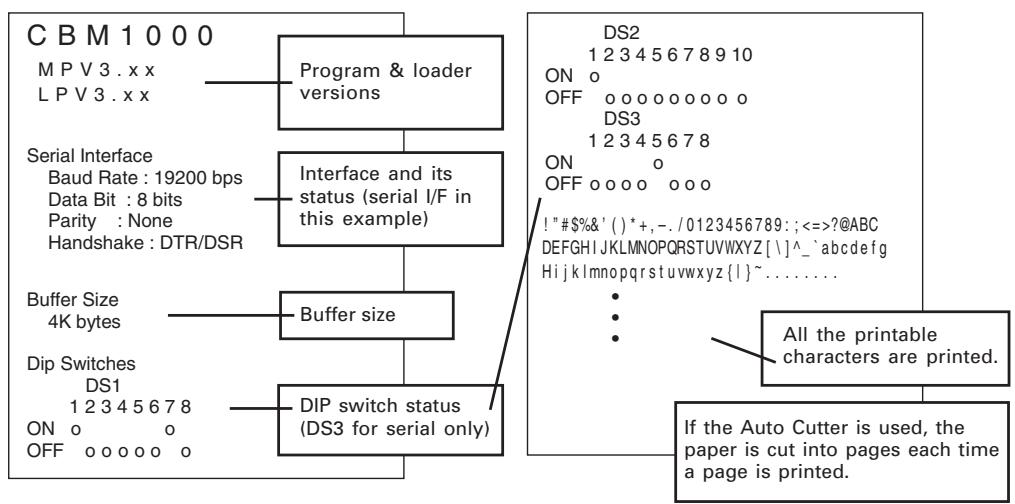
3.10 Self-printing
When the power is turned on while the FEED switch is pressed, the printer will perform preset printing. After the self-printing is completed, the printer will return to the normal operation conditions.
flowchart
graph TD
A["CBM1000"] --> B["Program & loader versions"]
B --> C["Interface and its status (serial I/F in this example)"]
C --> D["Buffer size"]
D --> E["DIP switch status (DS3 for serial only)"]
F["DS2"] --> G["ON o"]
G --> H["OFF 0 0 0 0 0 0 0 DS3"]
H --> I["ON o"]
I --> J["OFF 0 0 0 0 0 0 0 ! "#$%&'()*+,-./0123456789:;<=>?@ABC DEFGHIJKLMNOPQRSTUVWXYZ[\"]^`abcdefghijklmnopqrstuvwxyz{|}~......]
J --> K["All the printable characters are printed."]
L["Buffer Size 4K bytes"] --> M["Dip Switches DS1 1 2 3 4 5 6 7 8 ON o OFF 0 0 0 0 0 o"] --> N["If the Auto Cutter is used, the paper is cut into pages each time a page is printed."]
3.11 Hexadecimal Dump
1 Hexadecimal dump function allows data sent from the host computer to be printed in hexadecimal numbers as well as in characters corresponding to the numbers.
2 Starting hexadecimal dump
To start hex dump, turn the printer On while pressing and holding the FEED switch, with the printer cover left open. When you close the printer cover, the printer first prints "Hexadecimal Dump", then prints all the subsequent data in hex and characters.
=== Hexadecimal Dump ===
To terminate hexadecimal dump,
Press FEED switch three times.
1B 40 73 6D 70 6C 65 0A 30 31 32 .@sample.01
33 34 35 36 37 38 39 41 42 43 44 3456789ABCD
45 46 47 48 49 4A 4B 4C 4D 4F 50 EFGHI JKLMOP
51 52 53 54 55 56 57 58 59 5A 0D QRSTUVWXYZ.
61 62 63 64 65 66 67 68 69 6A 6B abcdefghijk
6C 6D 6E 6F 70 71 72 73 74 75 76 Imnopqrstuv
77 78 79 7A 0D 0A 0A 0A wxyz....
=== Completed ===
NOTE
- If a character is not available corresponding to the data received, “ . ” is printed instead.
- During hexadecimal dump, no other functions than DLE EOT and DLE ENQ work.
- If the data received is not enough for a full line, pressing the FEED switch causes the line to be printed.
3 Quitting hexadecimal dump
The printer exits Hex Dump mode when it is turned off, the FEED switch is pressed 3 times consecutively, or the printer receives a Reset signal from the interface, after hex dump is completed.
3.12 Printer Buffer
3.12.1 Buffering
The printer buffer has a capacity of 4K bytes (DS1-6: OFF). The host is released immediately after it transfers data to the printer.
3.12.2 Buffer Full Busy
If the printer buffer becomes full, the Busy/DTR signal is set to "High" to indicate "Buffer Full" to the host. The printer is unable to receive data from the host while in Buffer Full.
| Printer Buffer | Busy/DTR Asserted | Busy/DTR Reset |
| 4K bytes | 128 bytes remaining | 256 bytes remaining |
| 72 bytes | 20 bytes remaining | 30 bytes remaining |
Note: The printer buffer can be initialized with DS1-6.
3.13 Device ID
On receiving a Device ID request from the host, the printer returns a device ID as shown below through the parallel interface:
$$ < 0 0 > H < 3 1 > H $$
MFG:CBM;
CMD:CBM;ESC/POS;
MDL:CBM1000;
CLS:PRINTER;
The first 2 bytes of the device ID indicates the total length of the ID including itself.
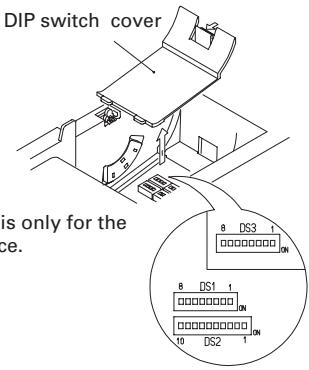
4. SETTING DIP SWITCHES
4.1 Location of DIP Switches
1 Turn off the power of the printer.
2 Open the printer cover.
3 Remove the paper roll and the DIP switch cover.
4 After completing the setting, place the cover to the original position.

CAUTION
- Do not make settings while the printer is turned on.
* DIP switch 3 is only for the serial interface.
4.2 Table for Setting DIP Switches
4.2.1 DIP switch 1
| No. | Function | ON | OFF | Factory presetting |
| 1-1 | Auto cutter | Available | Not available | ON |
| 1-2 | Unused | - | - | OFF |
| 1-3 | Paper width | 58 mm | 80 mm | OFF |
| 1-4 | Print columns* | 42 columns (80 mm)30 columns (58 mm) | 48 columns (80 mm)36 columns (58 mm) | OFF |
| 1-5 | CR mode | LF operation | Ignored | OFF |
| 1-6 | Input buffer | 72 bytes | 4K bytes | OFF |
| 1-7 | Print density (See the tabel below.) | ON | ||
| 1-8 | OFF | |||
* It will be different according to the setting of paper width (DS1 – 3).
Print density
| No. \Print density | Level 1 (Light) | Level 2 (Standard) | Level 3 (Slightly dark) | Level 4 (Dark) |
| 1-7 | OFF | ON | OFF | ON |
| 1-8 | OFF | OFF | ON | ON |
Note: If print density is set to level 2 (Standard) or over, print speed may decrease.
4.2.2 DIP switch 2
| No. | Function | ON | OFF | Factory presetting |
| 2-1 | Character code (See the table below.) | OFF* | ||
| 2-2 | OFF* | |||
| 2-3 | OFF* | |||
| 2-4 | OFF* | |||
| 2-5 | Unused | - | - | OFF |
| 2-6 | Condition for BUSY to occur | Reception buffer full | Off-line and reception buffer full | OFF |
| 2-7 | Paper | Thermal label paper | Thermal paper | OFF |
| 2-8 | Detection | Black mark | Label interval | OFF |
| 2-9 | Label length set | Command | Auto | OFF |
| 2-10 | Label Peeler | Available | Not available | OFF |
* Depends on destinations.
4.2.3 DIP switch 3
| No. | Function | ON | OFF | Factory presetting |
| 3-1 | Bit length | 7 bits | 8 bits | OFF |
| 3-2 | Parity | Available | Not available | OFF |
| 3-3 | Odd/even | Even number | Odd number | OFF |
| 3-4 | Communication mode | XON/XOFF | DTR/DSR | OFF |
| 3-5 | Baud rate (See the table below.) | OFF | ||
| 3-6 | ON | |||
| 3-7 | DSR | Reset | DSR | OFF |
| 3-8 | INIT | Reset | — | OFF |
* DIP switch 3 is only for the serial interface.
Selection of character code tables
| Code\No. | 2-1 | 2-2 | 2-3 | 2-4 |
| Code 437 (USA: Standard Europe) | OFF | OFF | OFF | OFF |
| Katakana (Japanese) | ON | OFF | OFF | OFF |
| Code 850 (Multilingual) | OFF | ON | OFF | OFF |
| Code 860 (Portuguese) | ON | ON | OFF | OFF |
| Code 863 (Canadian-French) | OFF | OFF | ON | OFF |
| Code 865 (Nordic) | ON | OFF | ON | OFF |
| Code 852 (Eastern Europe) | OFF | ON | ON | OFF |
| Code 866 (Russian) | ON | ON | ON | OFF |
| Code 857 (Turkish) | OFF | OFF | OFF | ON |
| Windows Code 1252 | ON | OFF | OFF | ON |
| Not defined | – | – | – | – |
| Blank page | ON | ON | ON | ON |
Baud rate
| Baud rate\No. | 3-5 | 3-6 |
| 4,800 bps | OFF | OFF |
| 9,600 bps | ON | OFF |
| 19,200 bps | OFF | ON |
| 38,400 bps | ON | ON |
- "Blank page" is an area for user registration, and is blank (space) by default.
- When "Katakana" is selected, the international character is set for Japanese. When the others are selected, it is set for USA.
5. MAINTENANCE AND SERVICE
For the information on maintenance and service, please contact our dealer.
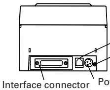
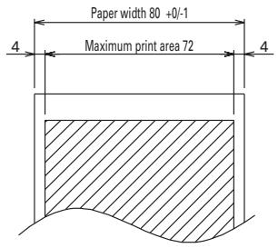
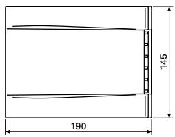
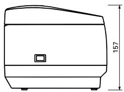
APPENDIX 1. OUTLINE DRAWING
- CBM1000IIS (Standard)

2.CBM1000IIA/CBM1000IID
natural_image
Line drawing of a mechanical component with a dimension label (157) and a small square mark on the side (no text or symbols present)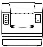
natural_image
Line drawing of a microwave oven with control panel and side-mounted dish (no text or symbols)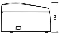
natural_image
Simple line drawing of a rectangular container with a side label and height dimension (no text or symbols)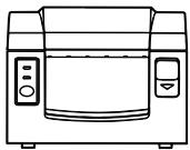
natural_image
Line drawing of a microwave oven with control panel and side-mounted dish (no text or symbols)APPENDIX 2. BLOCK DIAGRAM
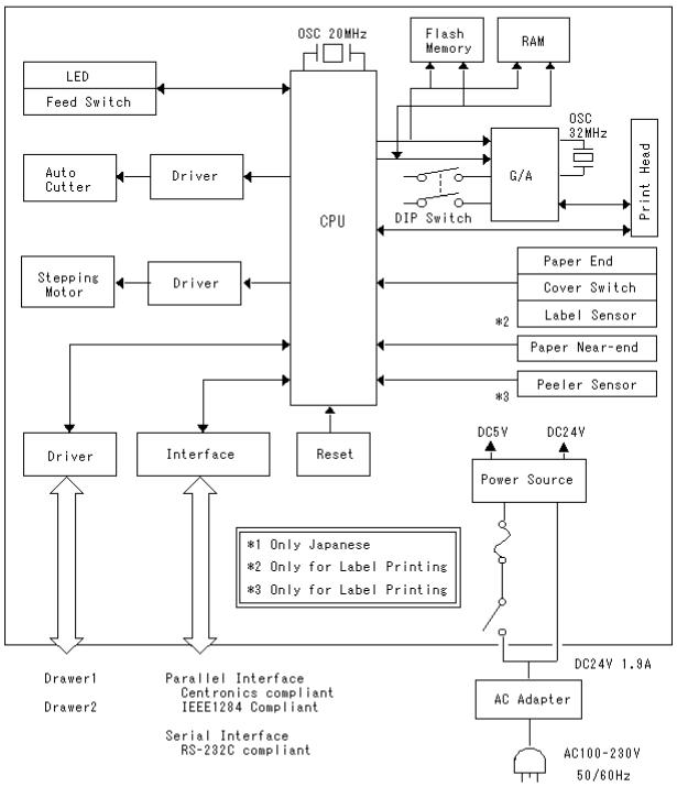
flowchart
graph TD
    A["CPU"] --> B["LED Feed Switch"]
    A --> C["Auto Cutter"]
    A --> D["Stepping Motor"]
    A --> E["Driver"]
    A --> F["Interface"]
    A --> G["Reset"]
    A --> H["DIP Switch"]
    A --> I["G/A"]
    A --> J["Flash Memory"]
    A --> K["RAM"]
    A --> L["Power Source"]
    L --> M["AC Adapter"]
    M --> N["DC24V 1.9A"]
    L --> O["DC5V"]
    L --> P["DC24V"]
    Q["*1 Only Japanese"] --> L
    R["*2 Only for Label Printing"] --> L
    S["*3 Only for Label Printing"] --> L
    T["Paper End"] --> U["Cover Switch"]
    V["Label Sensor"] --> W["Paper Near-end"]
    X["Peeler Sensor"] --> Y["Paper End"]
    Z["Power Source"] --> AA["AC100-230V 50/60Hz"]
    AB["Parallel Interface Centronics compliant IEEE1284 Compliant Serial Interface RS-232C compliant"] --> AC["Driver"]
    AD["Flash Memory"] --> AE["RAM"]
APPENDIX 3. IDENTIFICATION OF SEND STATUS
Because the status sent from the printer has certain fixed bits, it is possible to identify to which command the status belongs.
When using ASB (Automatic Status Back), however, the first byte of ASB should be checked, and then the three consecutive bytes except for XOFF should be treated as ASB data.
Identification of Send Status
| Command and function | Status |
| GS I | <0**0****>B |
| GS r | <0**0****>B |
| XON | <00010001>B |
| XOFF | <00010011>B |
| DLE EOT | <0**1**10>B |
| ASB (1st byte) | <0**1**00>B |
| ASB (2nd – 4th bytes) | <0**0****>B |
APPENDIX 4. PARALLEL INTERFACE
1 Bidirectional Parallel Interface (IEEE1284)
1.1 Compatibility Mode (Host → Printer communication: Centronics compliant)
(1) General description
This printer provides Compatibility Mode, which specifies the Centronics interface conventionally used for a wide variety of applications.
(2) Specifications
Data transfer method: 8 bit parallel
Synchronizing method: Controlled by nStrobe signal externally supplied
Handshaking: Handled by nAck and Busy signals
Signal level: All signals are TTL compatible
1.2 Reverse Mode (Printer → Host communication)
Data transfer from the printer to the host computer is conducted in Nibble or Byte Mode.
(1) Outline
The reverse mode has been devised to handle data transfer from an asynchronous printer controlled by a host computer.
In Nibble Mode, data is transferred, 4 bits (a nibble) at a time, using traditional control lines. In Byte Mode, data is transferred by making 8 bit data lines bidirectional. Note that either mode cannot work simultaneously with Compatibility Mode, thus resulting in half-duplex transmission.
2. Connector Pin Assignments
Host side Printer side D-Sub 25 pin (Male) IEEE1284-B (Receptacle)
| Pin No. | Signal name |
| 1 | nStrobe |
| 2—9 | Data0—7 |
| 10 | nAck |
| 11 | Busy |
| 12 | PError |
| 13 | Select |
| 14 | nAutoFd |
| 16 | nInit |
| 15 | nFault |
| 17 | nSelectIn |
| 18–25 | GND |
3. Connector Pin Configuration
| Pin | Source | Compatibility Mode | Nibble Mode | Byte Mode |
| 1 | Host | nStrobe | HostClk | HostClk |
| 2 | Host/Ptr | Data0(LSB) | Data0(LSB) | Data0(LSB) |
| 3 | Host/Ptr | Data1 | Data1 | Data1 |
| 4 | Host/Ptr | Data2 | Data2 | Data2 |
| 5 | Host/Ptr | Data3 | Data3 | Data3 |
| 6 | Host/Ptr | Data4 | Data4 | Data4 |
| 7 | Host/Ptr | Data5 | Data5 | Data5 |
| 8 | Host/Ptr | Data6 | Data6 | Data6 |
| 9 | Host/Ptr | Data7 | Data7 | Data7 |
| 10 | Printer | nAck | PtrClk | PtrClk |
| 11 | Printer | Busy | PtrBusy/Data3.7 | PtrBusy |
| 12 | Printer | PError | AckDataReq/Data2.6 | AckDataReq |
| 13 | Printer | Select | Xflag/Data1.5 | Xflag |
| 14 | Host | nAutoFd | HostBusy | HostBusy |
| 15 | NC | ND | ND | |
| 16 | GND | GND | GND | |
| 17 | FG | FG | FG | |
| 18 | Printer | Logic-H | Logic-H | Logic-H |
| 19—30 | GND | GND | GND | |
| 31 | Host | Init | Init | Init |
| 32 | Printer | nFault | nDataAvail/Data0.4 | nDataAvail |
| 33 | GND | GND | ND | ND |
| 34 | Printer | DK_STATUS | ND | ND |
| 35 | Printer | +5V | ND | ND |
| 36 | Host | nSelectIn | 1284-Active | 1284-Active |
NC: Not Connected
ND: Not Defined
Applicable connectors: Printer side: 57LE-40360 (Amphenol or equivalent)
Cable side: 57-30360 (Amphenol or equivalent)

CAUTION
- The first letter “n” of each signal name indicates that the signal is active “L”. If any one of the above signals is not available, bidirectional communication cannot be accomplished.
- In interfacing signals, be sure to use twist-paired wires for signal lines, and the return side must be connected to signal ground level. All interfacing conditions are specified based on C-MOS level and must satisfy the following characteristics. Also, specify the rising and falling time of each signal as 0.5 μs.
- Avoid transferring data by ignoring nAck or Busy signal; otherwise, the data may be erased. Make the interface cables as short as necessary.
4. Electrical Characteristics
4.1 Input and output conditions
All the input signals, DATA 0-7, are each pulled up with 50 KΩ resistor, and the other input signals are each pulled up with a 3.3 KΩ resistor.
The DK_STATUS signal is set to "High" if the Drawer switch is open, and set to "Low" if the switch is closed. The +5V signal is pulled up through a 3.3KΩ resistor.
4.2 Timing Chart (Compatibility Mode)
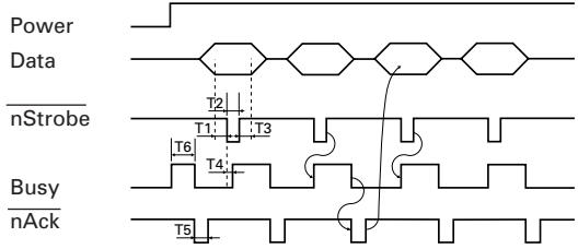
flowchart
graph TD
    A["Power"] --> B["Data"]
    B --> C["nStrobe"]
    C --> D["Busy"]
    D --> E["nAck"]
    style A fill:#f9f,stroke:#333
    style B fill:#ccf,stroke:#333
    style C fill:#cfc,stroke:#333
    style D fill:#fcc,stroke:#333
    style E fill:#cff,stroke:#333
T1, T2, T3: 0.5 μs MIN
T4: 270 ns MAX
T5: 2.3 μs TYP
T6: 500 ms MIN (At power-on)
APPENDIX 5. SERIAL INTERFACE
1 Specifications
(1) Synchronizing system:
Asynchronous
(2) Baud rate : 4800, 9600, 19200 or 38400 bps (User selectable)
(3) Configuration of one word
Start bit:
1 bit
Data bits:
7 or 8 bits (User selectable)
Parity bit:
Odd, even, or none (User selectable)
Stop bit:
1 bit or more
Transmission control:
DTR/DSR or XON/XOFF control (User selectable)
2 Connector Pin Assignments
Host side D-Sub 9 pin (Female)
| Pin No. | Signal name | Pin No. | Signal name | |
| Case | FG | 1 | FG | |
| 2 | RXD | 2 | TXD | |
| 3 | TXD | 3 | RXD | |
| 8 | CTS | 4 | RTS | |
| 4 | DTR | 6 | DSR | |
| 5 | GND | 7 | GND | |
| 6 | DSR | 20 | DTR |
Printer side D-Sub 25 pin (Male)
3. Connector Pin Configuration
| NO. | Signal name | I/O | Function |
| 1 | FG | Grounding for safety (Case ground) | |
| 2 | TD | Output | Transferred data |
| 3 | RD | Input | Received data |
| 4 | RTS | Output | Same as DTR |
| 6 | DSR | Input | Data set ready or reset (Selected with the DIP switches) |
| 7 | GND | Ground for signals (Common ground on the circuit) | |
| 20 | DTR | Output | Printer Busy signal |
| 25 | INIT | Input | Reset (Selected with the DIP switches) |
Applicable connectors (D-Sub connectors)
Printer side:
17LE-13250 (DDK or equivalent)
Cable side:
17JE-23250 (DDK or equivalent)

CAUTION
• Signals for RS-232C are specified based on EIA RS-232C.
- While data is not being transferred, be sure to maintain the received data in a mark state.
4. Electrical Characteristics
4.1 In/output signals
(1) RD
When a framing error, overrun error or parity error occurs, the data containing the error is printed as a “?”.
(2) DSR
If the DTR/SDR control is selected, the host sends data to the printer after it confirms that the DSR line is at space. If the XON/XOFF control is selected, the host sends data to the printer by ignoring the DSR signal status.
(3) INIT
This signal can be used as a reset signal after switching the DIP switches.
When the pulse width of the signal is 1 ms or longer in space state, a reset will be applied.
* Mark=logical "1" (-3 V to -12 V) * Space=logical "0" (+3 V to +12 V)
4.2 Data Configuration
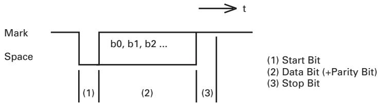
flowchart
graph TD
    A["Start Bit"] --> B["Data Bit (+Parity Bit)"]
    B --> C["Stop Bit"]
    D["Mark"] --> E["Space"]
    E --> F["b0, b1, b2 ..."]
    F --> G["(1)"]
    F --> H["(2)"]
    F --> I["(3)"]
Data status is read again 1/2 bit time after the falling edge of mark to space transition. If a space is detected, the data is recognized as a start bit. If a space is not detected, the data is not recognized as a start bit, and attempt is made again to detect a start bit.
The data is sampled 1 bit time after the start bit is detected.
Data bits are arranged in the order of bit 0, bit 1, bit 2, ..., and (stop bit), from the start bit toward stop bit.
APPENDIX 6. CONTROL COMMAND
For details on each command, see the command reference.
Command List
Print execution commands
| Command | Code | Function | Mode | GS P |
| LF | 0AH | Printing and paper feed | S/P | |
| CR | 0DH | Printing in PAGE MODE and returning to STANDARD MODE | S/P | |
| FF | 0CH | Printing in PAGE MODE and returning to STANDARD MODE/Printing and paper feeding to the top of the Label (Black mark position) | P | |
| ESC FF | 1BH 0CH | Printing data in PAGE MODE | P | |
| ESC J | 1BH 4AH n | Printing and feeding paper | S/P | |
| ESC d | 1BH 64H n | Printing and feeding the paper by “n” lines | S/P |
Print character commands
| Command | Code | Function | Mode | GS P |
| CAN | 18H | Canceling print data in PAGE MODE | P | |
| ESC SP | 1BH 20H n | Setting the right spacing of the character | S/P | * |
| ESC ! | 1BH 21H n | Collectively specifying the printing mode to STANDARD MODE | S/P | |
| ESC % | 1BH 25H n | Specifying/canceling download character set | S/P | |
| ESC & | 1BH 26H s n m [a p()]k | Defining the download characters | S/P | |
| ESC - | 1BH 2DH n | Specifying/canceling underline | S/P | |
| ESC ? | 1BH 3FH n | Deleting download characters | S/P | |
| ESC E | 1BH 45H n | Specifying/canceling emphasis printing | S/P | |
| ESC G | 1BH 47H n | Specifying/canceling double strike printing | S/P | |
| ESC M | 1BH 4DH n | Selection of character fonts | S/P | |
| ESC R | 1BH 52H n | Selecting the international character set | S/P | |
| ESC V | 1BH 56H n | Specifying/canceling 90°-right-turned characters | S | |
| ESC t | 1BH 74h n | Selecting the character code table | S/P | |
| ESC { | 1BH 7BH n | Specifying/canceling the inverted characters | S | |
| GS ! | 1DH 21H n | Specifying the character size | S/P | |
| GS B | 1DH 42H n | Specifying/canceling the black/white inverted printing | S/P | |
| GS b | 1DH 62H n | Specifying/canceling the smoothing | S/P |
Print position commands
| Command | Code | Function | Mode | GS P |
| HT | 09H | Horizontal tab | S/P | |
| ESC | 1BH 24H nL nH | Specifying the absolute positions | S/P | * |
| ESC D | 1BH 44H []k 0 | Setting horizontal tab position | S/P | |
| ESC T | 1BH 54H n | Selecting the character printing direction in PAGE MODE | P | |
| ESC W | 1BH 57H xL xH yL yH dxL dxH dyL dyH | Defining the print area in PAGE MODE | P | * |
| ESC \ | 1BH 5CH nL nH | Specifying the relative position | S/P | * |
| ESC a | 1BH 61H n | Aligning the characters | S/P | |
| GS | 1DH 24H nL nH | Specifying the absolute vertical position of characters in PAGE MODE | P | * |
| GS L | 1DH 4CH nL nH | Setting the left margin | S | * |
| GS W | 1DH 57H nL nH | Setting the print area width | S/P | * |
| GS \ | 1DH 5CH nL nH | Specifying the relative vertical position of a character in PAGE MODE | S/P | * |
Line feed span commands
| Command | Code | Function | Mode | GS P |
| ESC 2 | 1BH 32H | Specifying initial line feed span | S/P | |
| ESC 3 | 1BH 33H n | Setting line feed span of minimum pitch | S/P | * |
Bit image commands
| Command | Code | Function | Mode | GS P |
| ESC * | 1BH 2AH m n1 n2 []k | Specifying the bit image mode | S/P | |
| GS * | 1DH 2AH n1 n2 n1 n2 []k | Defining the download bit image | S/P | |
| GS / | 1DH 2FH m | Printing the downloaded bit image | S/P | |
| GS v 0 | 1DH 76H 30H m xL xH yL yH []k | Printing of raster bit image | S |
Status commands
| Command | Code | Function | Mode | GS P |
| DLE EOT | 10H 04H n | Sending status in real-time | S/P | |
| GS a | 1DH 61H n | Enabling/disabling ASB (Automatic Status Back) | S/P | |
| GS r | 1DH 72H n | Sending status | S/P |
Paper detection commands
| Command | Code | Function | Mode | GS P |
| ESC c 3 | 1BH 63H 33H n | Selecting the paper sensor valid for paper end signal output | S/P | |
| ESC c 4 | 1BH 63H 34H n | Selecting the Paper-Near End Sensor valid for print stop | S/P |
Panel switch command
| Command | Code | Function | Mode | GS P |
| ESC c 5 | 1BH 63H 35H n | Enabling/disabling the panel switches | S/P |
Macro commands
| Command | Code | Function | Mode | GS P |
| GS : | 1DH 3AH | Starting/ending macro definition | S/P | |
| GS ^ | 1DH 5EH n1 n2 n3 | Executing the macro | S/P |
Cutter command
| Command | Code | Function | Mode | GS P |
| GS V | (1)1DH 56H m(2)1DH 56H m n | Cutting the paper | S/P | * |
Bar code commands
| Command | Code | Function | Mode | GS P |
| GS H | 1DH 48H n | Selecting of printing position of HRI characters | S/P | |
| GS f | 1DH 66H n | Selecting the font of HRI characters | S/P | |
| GS h | 1DH 68H n | Specifying the height of the bar code | S/P | |
| GS k | (1) 1DH 6BH m []k0(2) 1DH 6BH m n []k | Printing the bar code | S/P | |
| GS w | 1DH 77H n | Specifying the horizontal size of bar code | S/P |
Flash memory commands
| Command | Code | Function | Mode | GS P |
| FS g 3 | 1CH 67H 33H a1a2 a3 a4 nL nH []k | Writing data into the flash memory | S | |
| FS g 4 | 1CH 67H 34H a1a2 a3 a4 nL nH | Reading data into the flash memory | S | |
| FS p | 1CH 70H n m | Printing the flash memory bit images | S | |
| FS q | 1CH 71H n []kn | Defining the flash memory bit images | S |
Label control commands
| Command | Code | Function | Mode | GS P |
| GS FF | 1DH 0CH | Printing and discharging the labels | ||
| GS < | 1DH 3CH | Initializing the printer mechanism | ||
| GS A | 1DH 41H m n | Correcting the label top position | ||
| GS C 0 | 1DH 43H 30H m n | Setting the numbering STANDARD MODE | ||
| GS C 1 | 1DH 43H 31H n1n2 n3 n4 n5 n6 | Setting the numbering counter mode (A) | ||
| GS C 2 | 1DH 43H 32H n1n2 | Setting the numbering counter | ||
| GS C ; | 1DH 43H 3BH N13BH N2 3BH N33BH N4 3BH N53BH | Setting the numbering counter mode (B) | ||
| GS c | 1DH 63H | Print the counter | ||
| GS I | 1DH 6CH n1L n1Hn2L n2H | Setting the label length |
Other commands
| Command | Code | Function | Mode | GS P |
| DLE ENQ | 10H 05H n | Real-time request to printer | S/P | |
| DLE DC4 | 10H 14H m n t | Outputting specified pulse in real-time | S/P | |
| ESC = | 1BH 3DH n | Data input control | S/P | |
| ESC @ | 1BH 40H | Initializing the printer | S/P | |
| ESC L | 1BH 4CH | Selecting PAGE MODE | S | |
| ESC S | 1BH 53H | Selecting STANDARD MODE | P | |
| ESC p | 1BH 70H m n1 n2 | Generating the specified pulses | S/P | |
| GS ( A | 1DH 28H 41H pL pH n m | Execution of test printing | S | |
| GS I | 1DH 49H n | Sending the printer ID | S/P | |
| GS P | 1DH 50H x y | Specifying the basic calculation pitch | S/P | |
| GS p | 1DH 70H n | Selecting the paper mode | S |
- In the Mode column: S = STANDARD MODE, P = PAGE MODE
* shows the command affected by GS P.
FRANÇAIS
TABLE DES MATIÈRES
1. PRÉSENTATION GÉNÉRALE ...... 9
APPENDIX 4. PARALLEL INTERFACE ....iii
APPENDIX 5. SERIAL INTERFACE ...... v
APPENDIX 6. CONTROL COMMAND ...... vii
PRÉCAUTIONS GÉNÉRALES
natural_image
Line drawing of a rectangular electronic device labeled 'Imprimante' (no other text or symbols)CBM1000 II R F 120 S - L
natural_image
Technical line drawing of a device rear panel with ports and connectors (no text or symbols)natural_image
Technical line drawing of a mechanical assembly with no visible text or symbolsAPPENDIX 4. PARALLEL INTERFACE ....iii
APPENDIX 5. SERIAL INTERFACE ...... v
APPENDIX 6. CONTROL COMMAND ...... vii
ALLGEMEINE VORSICHTSMASSREGELN
natural_image
Line drawing of a Drucker-branded printer (no text or symbols on the device itself)
Probierpapierrolle
CBM1000 II R F 120 S - L
natural_image
Technical line drawing of a mechanical assembly with mounting brackets and a central component (no text or symbols)Press FEED switch three times.
1B 40 73 6D 70 6C 65 0A 30 31 32 .@sample.01
33 34 35 36 37 38 39 41 42 43 44 3456789ABCD
45 46 47 48 49 4A 4B 4C 4D 4F 50 EFGHI JKLMOP
51 52 53 54 55 56 57 58 59 5A 0D QRSTUVWXYZ.
61 62 63 64 65 66 67 68 69 6A 6B abcdefghijk
6C 6D 6E 6F 70 71 72 73 74 75 76 Imnopqrstuv
77 78 79 7A 0D 0A 0A 0A wxyz....
=== Completed ===
HINWEIS
APPENDIX 4. PARALLEL INTERFACE ....iii
APPENDIX 5. SERIAL INTERFACE ...... v
APPENDIX 6. CONTROL COMMAND ...... vii
natural_image
Line drawing of a mechanical device labeled 'Stampante' (no other text or symbols)CBM1000 II R F 120 S - L
APPENDIX 4. PARALLEL INTERFACE ....iii
APPENDIX 5. SERIAL INTERFACE ...... v
APPENDIX 6. CONTROL COMMAND ...... vii
PRECAUCIONES GENERALES
natural_image
Line drawing of a portable electronic device with buttons and ventilation slots (no text or symbols)Impresora
CBM1000 II R F 120 S - L
Conector applicable:
TCP8927-63-1100 (Hosiden) o equivalente
TCP8927-53-1100 (Hosiden) o equivalente
natural_image
Technical line drawing of a mechanical assembly with mounting brackets and a central component (no text or symbols)- LINE THERMAL PRINTER
- MODEL CBM1000 TYPE II
- User's Manual
- Mode d'emploi
- Benutzerhandbuch
- Manuale dell'utente
- Manual de Usuario
- Ge
- Declaration of Conformity
- Sicherheitshinweis
- BASIC SPECIFICATIONS .... 10
- OPERATION 14
- SETTING DIP SWITCHES 22
- MAINTENANCE AND SERVICE 24
- APPENDIX 1. OUTLINE DRAWING ...... i
- APPENDIX 2. BLOCK DIAGRAM ....i
- APPENDIX 3. IDENTIFICATION OF SEND STATUS ...... ii
- APPENDIX 4. PARALLEL INTERFACE ....iii
- APPENDIX 5. SERIAL INTERFACE ...... v
- APPENDIX 6. CONTROL COMMAND ...... vii
- GENERAL PRECAUTIONS
- SAFETY PRECAUTIONS
- WARNING
- CAUTION
- Caution Labels
- DAILY MAINTENANCE
- GENERAL OUTLINE
- Features
- Unpacking
- BASIC SPECIFICATIONS
- Model Classification
- Outer Appearance and Component Parts
- Print Paper Specifications and Print Position
- Sensor Position and Cutter Position
- OPERATION
- Connecting the AC Adapter and AC Power Cord
- Connecting Interface Cables
- Connecting the Drawer Kick-Out Connector
- Setting/Replacing Paper Rolls
- Adjusting the Paper Near-End Sensor
- Using 58 mm Wide Paper Rolls
- Removing Jammed Paper
- Cleaning the Print Head
- Operation Panel and Error Indication
- POWER lamp (Green)
- ERROR lamp (Red)
- FEED switch
- Buzzer
- Description of errors
- Memory Check error:
- Cover open:
- Head overheat:
- Paper near-end:
- Paper end:
- Cutter motor lock:
- Low voltage error:
- High voltage error:
- Waiting for label cutter action:
- Waiting for Label Discharge:
- Label detection error:
- Self-printing
- Hexadecimal Dump
- NOTE
- Printer Buffer
- Buffering
- Buffer Full Busy
- Device ID
- SETTING DIP SWITCHES
- Location of DIP Switches
- Table for Setting DIP Switches
- MAINTENANCE AND SERVICE
- APPENDIX 1. OUTLINE DRAWING
- APPENDIX 3. IDENTIFICATION OF SEND STATUS
- APPENDIX 4. PARALLEL INTERFACE
- Bidirectional Parallel Interface (IEEE1284)
- Connector Pin Assignments
- Connector Pin Configuration
- Electrical Characteristics
- Input and output conditions
- Timing Chart (Compatibility Mode)
- APPENDIX 5. SERIAL INTERFACE
- Specifications
- Connector Pin Assignments
- In/output signals
- RD
- DSR
- INIT
- Data Configuration
- APPENDIX 6. CONTROL COMMAND
- Command List
- FRANÇAIS
- TABLE DES MATIÈRES
- PRÉSENTATION GÉNÉRALE ...... 9
- PRÉCAUTIONS GÉNÉRALES
- ALLGEMEINE VORSICHTSMASSREGELN
- HINWEIS
- PRECAUCIONES GENERALES
Brand : CITIZEN
Model : CBM-1000II
Category : Watch