ILLICO 2 - Tankless Water Heater THERMOR - Free user manual and instructions
Find the device manual for free ILLICO 2 THERMOR in PDF.
User questions about ILLICO 2 THERMOR
0 question about this device. Answer the ones you know or ask your own.
Ask a new question about this device
Download the instructions for your Tankless Water Heater in PDF format for free! Find your manual ILLICO 2 - THERMOR and take your electronic device back in hand. On this page are published all the documents necessary for the use of your device. ILLICO 2 by THERMOR.
USER MANUAL ILLICO 2 THERMOR
The device you have just purchased was submitted to many tests and checks ensuring its quality. We thank you for your choice and trust. We hope you will be fully satisfied.
A few recommendations:
Read the instructions before installing the device.
Power the device off before intervening on it, and check the power supply voltage.
Store the instructions, even after installing the device.
Classification of the device: (shown on the information label)
Cat C : Complies with EU standards for this category.
IP24 : Protected against water projections.
Classe II : Dual insulation.
INSTALLING THE DEVICE
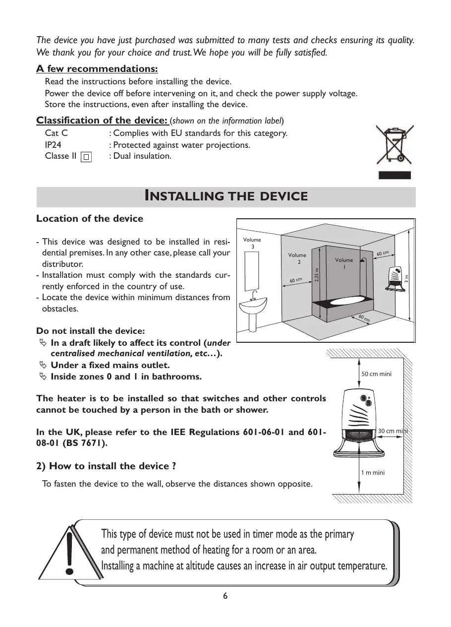
Location of the device
- This device was designed to be installed in residential premises. In any other case, please call your distributor.
- Installation must comply with the standards currently enforced in the country of use.
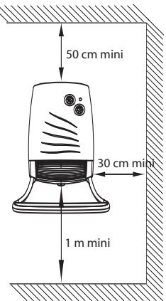
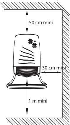
- Locate the device within minimum distances from obstacles.
Do not install the device:
In a draft likely to affect its control (under centralised mechanical ventilation, etc...).
Under a fixed mains outlet.
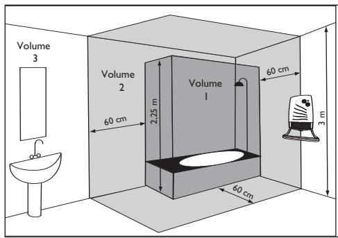
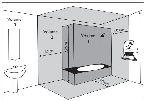
Inside zones 0 and 1 in bathrooms.
The heater is to be installed so that switches and other controls cannot be touched by a person in the bath or shower.
In the UK, please refer to the IEE Regulations 601-06-01 and 601-08-01 (BS 7671).
2) How to install the device?
To fasten the device to the wall, observe the distances shown opposite.

This type of device must not be used in timer mode as the primary
and permanent method of heating for a room or an area.
Installing a machine at altitude causes an increase in air output temperature.
2-1) Fastening the bar (version with the bar).
- Proceed to install the front bar before fastening the device to the wall.
- Lay your device flat and screw in the four fixing screws.
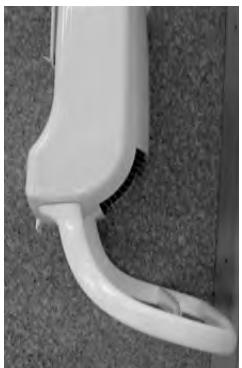
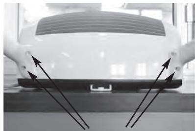
Bar fixing screws
GB
2-2) Fastening the device to the wall.
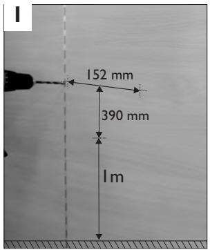
Mark out the 3 fixing holes and insert the plugs.
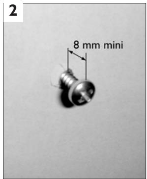
Screw in the 2 upper screws leaving a minimum of 8mm between the head of the screw and the wall.
Slide the device into the niches created by the two upper screws. Fasten the device in place firmly with the bottom screw.
2-3) Connecting the device.
- The device must be supplied with 230/240V 50Hz.
- It is connected to the electricity supply by means of a 2 core cable (Brown=Live,Blue=Neutral) via a connection box. In damp areas such as bathrooms and kitchens, the
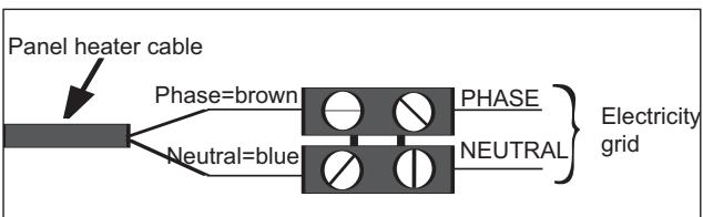
connection box must be installed at least 25~cm above the floor.
- To prevent hazards due to unintentional resetting of the thermal circuit breaker, this device should not be powered through an external switch, such as a time switch, or connected to a circuit which is switched on and off on a regular basis by the electric power supplier.
- The installation must include a double-pole cutout with a contact opening distance of at least 3mm .
- The device must not be earthed.
- If the supply cable is damaged, it must be replaced by the manufacturer, his after-sales service or a similar person of qualification in order to avoid a danger.
USING THE DEVICE
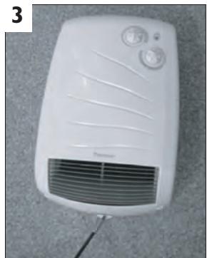
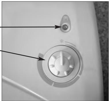
I) Description of the control box
Timer version
Basic version
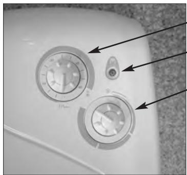
1 Timer knob
Heating indicator
Heating knob
2) Ambient heating
To determine the position of the Heating knob 3 for the desired temperature, proceed as follows:
- Turn the knob ③ fully to the right and wait for the room to reach the desired temperature.
- Then turn the knob ③ to the left until you hear the thermostat contact click.
- Turn the knob back slightly and leave the device to run by itself.
- It may be necessary to correct the setting subsequently. To increase the temperature, turn the knob slightly clockwise. To reduce the temperature, turn the knob anticlockwise. Continue in this way until you are satisfied with the temperature setting.
- To stop the device, set the knob ③ to the minimum position.
3)Rapid room heating (version with timer)
- Set the heating knob ③ to the ambient temperature desired.
- Set the timer's knob ① to the period of rapid heating desired (operation at 1800W). The device will then run at 1800W in accelerated pre-heating mode for the selected period of time and will then operate at 1000W to maintain the ambient temperature according to the thermostat setting.
4) Frost mode
This is the mode that enables you to maintain the temperature in the room at approximately 7^ during a prolonged absence (generally for more than 24 hours).
Set the heating knob ③ to position
5) Installing the filter.
The filter can be installed from the left or the right side depending on your installation.
RECOMMENDATIONS OF USE
- It is useless to set the heating knob ③ to the maximum position, the room will not heat up any faster.
- When you air the room, set the knob ③ to the minimum position.
WARNING
- Do not let children lean on the front and the bars of the device.
- This device is not intended for use by persons (including children) with physical, sensory or mental disability, or by persons lacking experience or knowledge, unless they have received from a person in charge of their safety adequate supervision or preliminary instructions on how to use the device.
- Prevent children from climbing on the device.
- Do not cover the device: this can cause it to overheat.
- Ensure you do not let foreign objects or paper fall into the device.
- Any work inside the device must only be performed by a qualified technician.
- The bars must only be used for drying towels.
MAINTENANCE
- The front of the device can be cleaned with a damp cloth.
- Never use abrasive products.
- To maintain the device's performance, you must remove the dust from the device's grills and the filter at the back of the device. The filter can be installed from the left or the right side depending on your installation. Extract the filter and clean it with a vacuum cleaner.

IN CASE OF PROBLEM
| Problems encountered | Checks to make |
| The device does not heat. | - Check the air temperature in the room and the thermostat's setting. - Ensure that the installation's circuit breakers are closed or that the cut-off switch (if you have one) has not cut off the power supply to the device. - The device is fitted with an overheat safety device. The safety limit switch will cut off the electrical power automatically to avoid any problems. Proceed as follows to switch the device on again: - Switch off the power supply to the device. - Eliminate the causes of the device operating abnormality (objects and/or dirt blocking the air outlet grill or the space left between the device and the wall). - Check the filter at the back of the device and clean it if necessary (see the 'Maintenance' section). - Wait approximately 15 minutes and then switch the device on again. |
| The device heats all the time. | - Check that the device is not located in a draught or that the temperature setting has not been altered. |
WARRANTY CONDITIONS
KEEP THIS DOCUMENT IN A SAFE PLACE
(To be presented by the user only in the event of a claim)
- The guarantee period is two years from the date of installation or purchase and may not exceed 30 months from the date of manufacture in the absence of a receipt.
- The guarantee covers the replacement and supply of components recognised as being defective, excluding any damages or interest.
- The user is responsible for any labour or transport costs.
- The guarantee does not cover any damage arising from improper installation, abnormal use or nonobservance of the requirements of the said instructions for installation and use.
- The stipulations of the present guarantee conditions do not exclude any of the purchaser's legal rights of guarantee against faults or hidden defects, which are applicable in all cases under the stipulations of Articles 1641 of the Civil Code.
- Present this certificate to your distributor or installer only in the event of a claim, together with your purchase invoice.
TYPE OF DEVICE*:
SERIAL NUMBER*:
CUSTOMER'S NAME AND ADDRESS:
- This information can be found on the information plate situated on the left-hand side of the device.
ATLANTIC INTERNATIONAL
Tel: (33) 146836000
Fax: (33) 146836001
::Annapat 3aunuienoT nonanaHnBHytpb Hero 6pb13r BODbl.
Classe II
:Annapat cna6xen DBOHNO 3eKtpo3OJIaIeN
IYCTAHOBKA ANNAPATA
1)Гдустанови恼аannapat?
-Даннь annapat npedna3haeHдя уctahOBkn B JINOM nomeuHn. B JIO60m dpyrom cnyae 6bpatntecb K NOCTaBunKy.
- YCTaHOBkaДОЛЖHA BbIOnJIHЯTbCBA COOTBeTCTBm C npaBnJaMn I DeIcTByUOuIMN B CTpaHe YCTaHOBKn cTaHdApTaMn (ДлЯФанци 3TO cTaHdApT NFC 15100).
He yctanabnbaite annapa:
B Mectax, rne notok Bo3dyxa MoKET nomeMaTb peryInpOBe annapata (noD OTBepCTnEM ceHTpaHn3OBaHHoMexaHnueckoB BeHTnlaun n T. n.).
-ПдФнкрованно 3лЕКтпческо розтко.
B 30He 1 BaHHoN KOMHaTbI.
B 30he 2, ecn yenobek, haxoJusncB dywe nB aHHe moKet doTpoHytbcdo orpraHOB ynpabJIeHn annapaTom.
2)Поdkлоченеannapata
PnKpeHneHHyCTPOHCTBaHa cTeHe,co6JIHOaIte yka3aHhbIe pacCTOHHN.

Даньи ТИУстpo�CTBa He ДОлжЕн ИСПОЛБ3OBaTbСЯ C Функциeп pele BpeMeHиΚak OCHOBHOe И NOCTOЯHHOE ySTpoIcTBО OTONJIeHnI KOMHaTbI ИИ NOMeUeHnI.
2-1)3akpenTe wTaHry (Bepcnco wTaHro).
UcTaHOBnTepepyrJrTOpBNoIOnKeHne