Familio 150L - Water heater THERMOR - Free user manual and instructions
Find the device manual for free Familio 150L THERMOR in PDF.
Frequently Asked Questions - Familio 150L THERMOR
User questions about Familio 150L THERMOR
0 question about this device. Answer the ones you know or ask your own.
Ask a new question about this device
Download the instructions for your Water heater in PDF format for free! Find your manual Familio 150L - THERMOR and take your electronic device back in hand. On this page are published all the documents necessary for the use of your device. Familio 150L by THERMOR.
USER MANUAL Familio 150L THERMOR
DESCRIPTION OF THE APPLIANCE
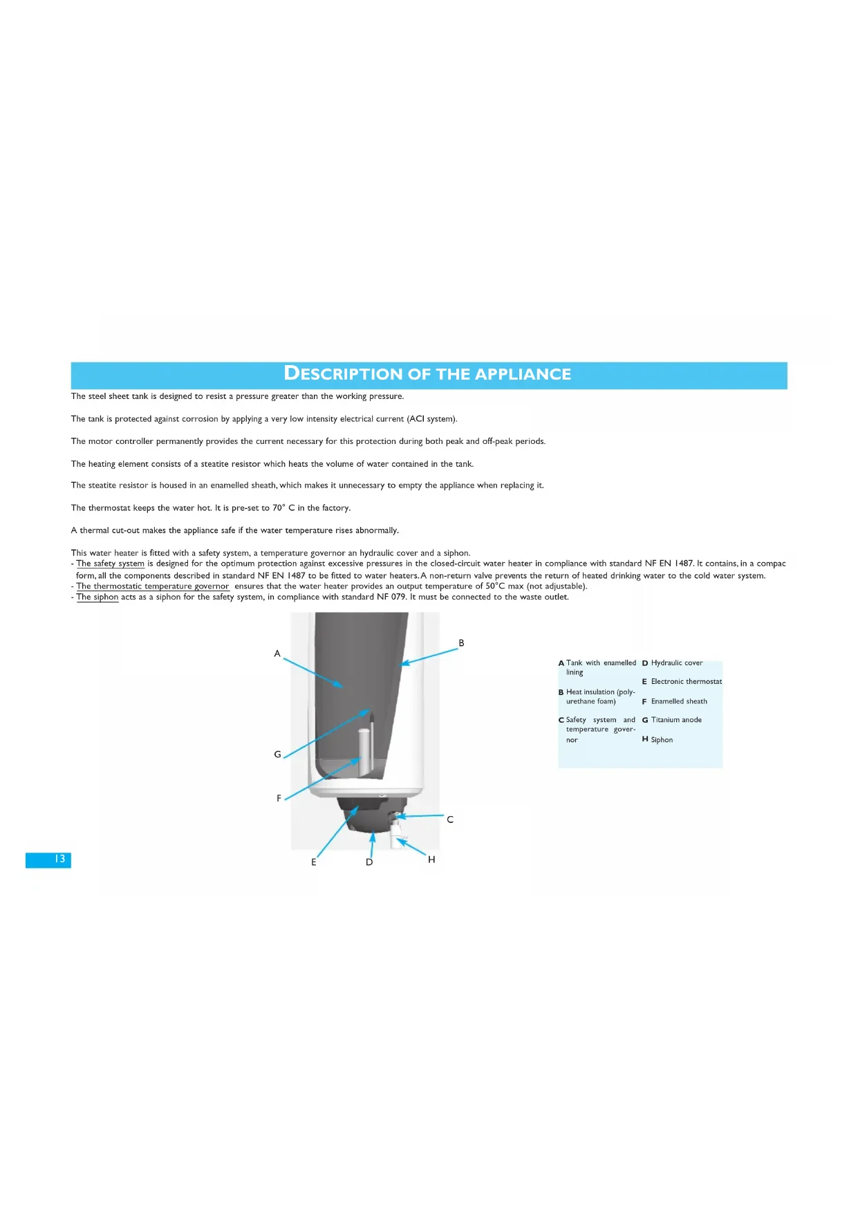
The steel sheet tank is designed to resist a pressure greater than the working pressure.
The tank is protected against corrosion by applying a very low intensity electrical current (ACI system).
The motor controller permanently provides the current necessary for this protection during both peak and off-peak periods.
The heating element consists of a steatite resistor which heats the volume of water contained in the tank.
The steatite resistor is housed in an enamelled sheath, which makes it unnecessary to empty the appliance when replacing it.
The thermostat keeps the water hot. It is pre-set to 70^ C in the factory.
A thermal cut-out makes the appliance safe if the water temperature rises abnormally.
This water heater is fitted with a safety system, a temperature governor an hydraulic cover and a siphon.
The safety system is designed for the optimum protection against excessive pressures in the closed-circuit water heater in compliance with standard NF EN I487. It contains, in a compa
form, all the components described in standard NF EN 1487 to be fitted to water heaters. A non-return valve prevents the return of heated drinking water to the cold water system.
- The thermostatic temperature governor ensures that the water heater provides an output temperature of 50^ max (not adjustable).
The siphon acts as a siphon for the safety system, in compliance with standard NF 079. It must be connected to the waste outlet.

A Tank with enamelled lining
D Hydraulic cover
Electronic thermostat
B Heat insulation (polyurethane foam)
F Enamelled sheath
C Safety system and temperature governor
G Titanium anode
H Siphon
INSTALLING THE APPLIANCE
Install the water heater in a frost-free place.
Position it as close as possible to the points of major use of water.
Installation inside the house is best; if it is placed outside (in a cellar or garage for instance), insulate the pipe-runs.
The ambient temperature around the water heater ought not to exceed 40^ continuously.
Make sure that the supporting wall or floor and the fixings (plugs and bolts) are strong enough to carry the weight of the heater when full of water.
Allow an adequate clearance of 500mm in front of all electrical equipment for the routine maintenance of the heating element.
Install a drip-tray under the water heater if it is installed in a false ceiling, loft, or over inhabited rooms. A waste outlet connected to the drain is compulsory.
The heater is easily moved by lifting handles built into the ends. There are several ways of fixing it, depending on the nature of the walls:
A) Thin walls (plasterboard partitions): 10 mm threaded rods traversing the wall, connected by profiles or backplates.
B) Hard, thick walls (concrete, stone or brick): cement in 10mm bolts, or drill to take MOLY type 10mm plugs.
For both types of walls, use the drilling template printed on the carton and check the measurements before drilling.
C) 100, 150-200 litres water heaters can be mounted on a stand if the wall cannot take the weight of the appliance. It is essential to fix the upper strap. Use the stand recommended by the maker (available as an extra).
D) In the case of large-capacity water heaters (250 and 300 L), the stand is supplied with the water heater. The appliance must be installed on a level surface.

100, 150 and 200 Litres

250 and 300 Litres
A restraining bracket must be fixed to the wall for the 250 l and 300 l models to prevent the appliance falling accidentally when top-heavy (the restraining bracket can be screwed into the top of the heater if necessary).

Assembly on the stand with by I person :


Specifically if installing in a bathroom :
The water heater should be fitted in zone 3 or outside all zones (NFc 15100). If the bathroom is too small to place it in these zones, this appliance can however be installed in zone 2 but it is forbidden in zones 0 and 1).

CONNECTING THE WATER
The water heater must be connected to the water supply in accordance with standards and with the regulations in force in the country where it will be installed (for France, D.T.U. 60.1).
Pipes to the appliance
Each pipe on the water manifold is in brass; the ends have a 20/27 gas-pipe thread.
The cold water inlet and the hot water outlet are identified by coloured washers: blue and red respectively.
Connections to the pipes
To avoid corrosion of the piping, the dielectric function is built into the water manifold and complies with NFC 15-100 (it is therefore not necessary to use a dielectric connector).
The pipe-runs can be rigid, generally in copper (black steel is forbidden), or flexible (flexible stainless steel braid).
Make sure that connections to the pipe-runs are water-tight; this also applies when PER tubing is used.
The siphon should be connected to a waste-water outlet.
An expansion tank can be installed (see diagram).

The pressure of the cold water system is generally less than 5 bar.
If it is not, fit a 3-bar pressure reducer, which must be positioned on the mains cold water inlet of the home, after the meter.
The temperature of the water entering the water heater (D) must be less than 50^ (take care when dealing with installations in series).

A Connector nuts
E Drain to waste outlet
B Temperature govern
F Hydraulic cover
C Hot water outlet (limited to 50^ red)
Safety system
D Cold water inlet (blue)
H Siphon

Expansion tank

Hydraulic cover assembly


ELECTRICAL CONNECTIONS
Our appliances comply with the standards in force and are therefore perfectly safe. The electrical connections must comply with installation standard NF C 15-100 and with the provisions in force in the country where the water heater will be installed (label, etc.).
The installation consists of:
A multi-pole circuit-breaker with contacts opening at least 3 mm.
A rigid mains cable of minimum section 3 × 2.5 ~mm^2 monophase (phase, neutral, earth) or 4 × 2.5 ~mm^2 three-phase (3 phases + earth).
The earth conductor will be coloured green/yellow.
The electronic generator of your "applied current anode" water heater was designed for a supply of 8 h minimum per day, broken or continuous. Make sure that the installation receives this supply. If the duration is less, the conditions of guarantee will not apply.
GB
Connection procedure
First unscrew the retaining screw and remove the protective cover. A diagram of the electrical connections will be found inside.
This water heater is pre-wired in 230V monophase. For 400V three-phase, you must replace the original monophase plate with a 400V three-phase kit (available as an extra). The procedure for installing this kit is given in the instructions enclosed with it.
Connect the ends of the thermostat cable to the screw terminals provided (there is no need to dismantle the thermostat).
Connect the green/yellow earth wire to the terminal marked on the door of the water heater.
Check that the connection terminals are tightened correctly, and replace the cover.
Tighten the retaining screw.
Recommendations
Cut the cable to an appropriate length to avoid contact with the heating elements.
Direct connection to a mains socket is forbidden.
The earth connection is essential for safety raisons.
Before finally connecting the appliance, make sure it is full of water. If it is not, for safety reasons to prevent it boiling dry, the element will not operate.

Direct connection to the elements (without passing through the thermostat) is strictly forbidden. It is dangerous because the temperature of the water is not controlled. Direct connection to the elements (without passing through the thermostat) is strictly forbidden. It is dangerous because the temperature of the water is not controlled.
COMMISSIONING
Fill the water heater
- Open one or more hot water taps (sink, shower, etc.).
- Open the cold water tap on the safety system (see illustration).
- When the hot water taps begin to run, close them. Your water heater is full of water.
- Check the pipe connections do not leak.
- Check the waste outlet is connected.
- Check the hydraulic components are working properly by opening and closing the safety system drain tap, to drain off any sediment.
Checking that the appliance works
-
Switch on the power.
-
If your electric board is fitted with a relay to take advantage of off-peak rates (reduced prices at night), set the switch to "permanently on" or "I". After 15 to 30 minutes, the water may drip out of the drain outlet of the safety system in the siphon. This should be connected to the waste water drain.
This phenomenon is quite normal, caused by the water expanding as it warms up. Consequently, the safety valve will allow a small quantity of water out so that the internal pressure in the tank does not exceed 7 bars. This escape may represent 2 to 3% of the capacity of the tank throughout the entire heating.
- Check again that the connections are watertight. If all is well, set the switch to "automatic".
An indicator light is situated on the electric cover. It has 3 settings:
If it is green: the ACI system is running properly and your water heater is protected from corrosion.
If it turns orange: the heating element of your water heater works. The water is heating up (the ACI also operates during this warm-up phase).
If the light is out: your water heater is not operating correctly. You should contact your installer (refer to the paragraph Trouble-shooting for professionals).
About 15 minutes after switching on the water heater, check the light on the cover.
This indicator light should be permanently on, 24 hours a day.
NOTE While heating up, depending on the quality of the water, the water heater may make a quiet noise like a kettle. This noise is normal and does not mean there is anything wrong with the appliance.

DOMESTIC MAINTENANCE
A water heater needs little domestic maintenance by the user: manipulate the safety system and the stop tap once a month, and check the drips.
Periodically check the indicator light is working. If it stops, contact your installation consultant.
If there is a malfunction, the water does not heat or steam comes out of the tap, switch off the electric supply and call your installer.
In regions where the water is very hard (Th > 20^) you are advised to treat it. With a softener the hardness of the water should remain above 12^ . The softener has no adverse effect on our guarantee, as long as it is CSTB-approved for France and adjusted according to good practice, regularly checked and maintained.
- Decree no. 2001-1220 of 20 December 2001 and circular DGS/SD 7A.
- Decree no. 2002-571 of 25 November 2002.
- Complies with DTU 60,1
GB
MAINTENANCE BY AN APPROVED PROFESSIONAL
To keep your appliance in good working order for many years, you need to have the equipment checked by a professional every two years (every year in the installations where the water is of poor or unknown quality). The procedure is as follows:
- Switch off the electric supply to the appliance (protection).
- Remove the hydraulic cover
- Unscrew the cap of the thermostat.
- Disconnect the wires from the terminals of the thermostat.
-
Empty the tank:
-
Turn off the cold water tap to the safety system,
- open a hot water tap,
-
Set the valve of the safety system to the drain position.
-
Once the water has drained, remove the thermostat and its plastic support, after having disconnected the different sets of wires.
- Dismantle the heater unit.
- Remove any scale deposited as sludge or scales on the bottom of the tank and carefully clean the sleeves of the elements and the thermostat. Do not scrape or knock the scale adhering to the walls, for fear of damaging the lining.
- The anode is in titanium and needs no maintenance.
- Reassemble the heater unit, using a new gasket and tightening the nuts gradually and without forcing (tighten alternately). Reassemble and connect the thermostat.
- Reassemble the hydraulic cover.
- Fill the water heater, leaving a hot water tap open; when the water runs out it means that the water heater is full.
- Check that the joint is watertight and only then replace the thermostat and its support and reconnect the electric supply.
- The next day, check again that the joint is watertight, and if necessary tighten the nuts slightly.
Maintenance of the temperature governor
- You are advised to check the condition of the temperature governor every two years. Use a thermometer to measure the temperature of the hot water at the tap closest to your heater: it should be 50^ .
- The temperature governor cannot be dismantled. Do not try. If it breaks down, replace it.
- This governor is a safety valve. You are advised to replace it every five years at least.

Maintening the filter
TROUBLE-SHOOTING FOR PROFESSIONALS
GB
| TYPE OF FAILURE | POSSIBLE CAUSE | DIAGNOSIS AND REPAIR |
| †No hot water | This water heater is fitted with a function preventing it from boiling dry. If the heater is not full of water, the safety function is activated and cuts off the electric supply to the heating element. | Check that the water heater is actually full by opening a hot water tap.Check the connection of the connector and earth lead. |
| †Does not heat up†No hot water | No electric supply to the heater: day/night contactor not working, fuse, etc... | Switch to "permanently on" and check that power is reaching the terminal block feeding the electronic thermostat. |
| Heating element or its wiring faulty. | Check that power is reaching the heating element connector between the blue and red wires. | |
| Circuit broken: wiring badly connected or cut. | Visual check on the wiring connections. | |
| †Water not hot enough* | Electric supply to the heater cut off too soon: day/night contactor not working... | Check the day/night contactor is working properly. |
| Heating element or its wiring partly faulty. | Check the three plug resistors on the connector of the plug wiring set, and that the wiring set is in good condition. | |
| †Indicator light off | Short-circuit on wiring: no protection. | Indicator light still off: contact the after-sales department. |
| †If the system uses off-peak electricity: Indicator light off at peak times | Accumulator not workingNow: the accumulator is recyclable and ought not to be thrown away. | Indicator light off at times when the water heater receives no electric supply: replace the accumulator. |
| †Other malfunctions | Contact the after-sales department for any other malfunctionThe address is given on the last page of the instructions. | |
| †Hot water tap runs slowly | Filter dirty Clean the filters (see chapter on maintenance) | |
| †Loss of water through the safety system | Safety group damaged or dirty Replace the safety group | oup |
| †Temperature of water unstable at the tap | Temperature governor dirty Replace the temperature governor |
Maintenance and repairs should be done by an approved professional only.

Never supply the heating element directly with electricity.
*This product delivers water at a safe 50^ C so as not to scald the user. However this may mean changing your family habits.
DIAGRAM FOR CONNECTING THE WATER HEATER FOR THE USE OF PROFESSIONALS

AFTER-SALES DEPARTMENT
The parts of the water heater that can be replaced are as follows (consult us for special parts):
The flange gasket
The electronic thermostat assembly
The heating element (steatite resistor)
he heating body for steatite resistor
The safety system
The temperature governor
The hydraulic cover
The filters on the governor
The adjustment sensor
The accumulator
Any repairs to electrical parts should be left to a specialist.
Only use spares approved by the maker.
When placing orders, specify the exact type of the water heater, its capacity, the type of equipment, three-phase or monophase, and its date of manufacture.
All these details appear on the identification plate fastened to the appliance near the electrical equipment.
RECOMMENDATIONS APPROVED BY GIFAM (THE INTERPROFESSIONAL GROUP OF DOMESTIC APPLIANCE MANUFACTURERS)ON
THE CORRECT INSTALLATION AND USE OF THE PRODUCT
Mechanical risks :
- Handling:
The appliance must be handled and installed in a way suited to the weight and size of the appliance.
- Location:
- The appliance should be sheltered from the weather and protected from frost.
- Positioning:
- The appliance should be positioned as recommended by the manufacturer.
Fixing:
- The support and fittings must be able to supporter at least the weight of the appliance filled with water. All the fixing points provided by the manufacturer must be used.
Electrical risks :
Connections:
- Connect the appliance according to the manufacturer's diagrams and instructions. Take particular care not to neutralise the thermostat; direct connection is forbidden.
- To avoid the supply cable overheating, use the type and section of cable recommended in the installation manual. In any event, comply with the regulations in force.
- Make sure that there is an electrical protection between the mains and the appliance and user (for example in France, a 30 mA differential circuit-breaker).
- Check the connections are tight.
- The appliance must be connected to a good earth connection.
- Ensure that live parts remain inaccessible. Covers must be present in their original condition and openings for cables of a suitable diameter.
This appliance complies with Directives 2004/108/EEC regarding electromagnetic compatibility and 2006/95/EEC regarding low-tension systems.
Hydraulic risks :
Pressure:
- The appliances must be used within the range of pressures for which they were designed.
- Connection, drains:
- Do not block the drain opening of the valve. Connect the drain opening of the valve to a waste water outlet.
Take care not to reverse the hot water and cold water connections. - Check there are no leaks.
Use
Nature of the product:
- This appliance is intended exclusively to supply domestic hot water.
Abnormal use:
-
In the event of malfunction, call in a professional.
-
Do not switch on power if the appliance is empty.
Scalds, bacteria:
- For hygiene raisons, hot water should be stored at a high temperature. This temperature may scald.
- Take the necessary precautions, using mixer taps for example, to avoid any accident when drawing water. If the appliance is unused for a long period, run off the nominal capacity of water before the first use.
Maintenance :
Periodically ensure that the hydraulic safety device is operating correctly as recommended by the manufacturer.
- Before making any adjustments, turn off the appliance.
Modifications :
- All modification of the appliance is forbidden. Components should be replaced by a professional using the correct parts.
End of life :
- Before dismantling the appliance, unplug it and empty it.
- Do not burn the appliance.
SAFETYINSTRUCTIONS
This appliance is not intended to be used by people (including children) with reduced physical, sensory or mental capabilities or by people inexperienced with or lacking knowledge of the appliance, unless they are under the supervision of a person responsible for their safety or have received prior instructions from such a person regarding how to use the appliance.
Children should be supervised to ensure that they do not play with the appliance.
TECHNICAL CHARACTERISTICS
| Capacity (L) | Heating element | Power (W) | Dimensions / (mm) | Actual heating time | QPR (maintenance consumption) | V40 (hot water quantity 40°C) | Weight without water (Kg) | |||||
| o H | A B C D | |||||||||||
| 100 | Steatite | 1200 | 508 | 925 810 | --- | - | - | - | 5h37 | 1,30 | 1,87 | 33 |
| 150 | 1800 | 530 | 1165 1050 800 - | - | - | - | - | 5h20 | 1,50 | 1,96 | 42 | |
| 200 | 2200 | 1480 1050 800 - | - | - | - | - | 5h50 | 1,79 | 1,91 | 51 | ||
| 250 | 3000 | 570 | 1565 1525 - 1845 | 1795 | - | - | - | 5h20 | 2,06 | 1,92 | 63 | |
| 300 | 3000 | 1810 1770 - 2090 | 2040 | - | - | - | 6h35 | 2,36 | 1,89 | 70 | ||
Voltage (V): 230V monophase (transformable into 400V three-phase with the kit or 230V three-phase with the appropriate kit).
Actual time taken to heat the tank under standard conditions.
Maintenance consumption in KWh per 24 hours under standard conditions.