NBG-415 - Router ZYXEL - Free user manual and instructions
Find the device manual for free NBG-415 ZYXEL in PDF.
User questions about NBG-415 ZYXEL
0 question about this device. Answer the ones you know or ask your own.
Ask a new question about this device
Download the instructions for your Router in PDF format for free! Find your manual NBG-415 - ZYXEL and take your electronic device back in hand. On this page are published all the documents necessary for the use of your device. NBG-415 by ZYXEL.
USER MANUAL NBG-415 ZYXEL
Copyright © 2006 by ZyXEL Communications Corporation.
The contents of this publication may not be reproduced in any part or as a whole, transcribed, stored in a retrieval system, translated into any language, or transmitted in any form or by any means, electronic, mechanical, magnetic, optical, chemical, photocopying, manual, or otherwise, without the prior written permission of ZyXEL Communications Corporation.
Published by ZyXEL Communications Corporation. All rights reserved.
Disclaimer
ZyXEL does not assume any liability arising out of the application or use of any products, or software described herein. Neither does it convey any license under its patent rights nor the patent rights of others. ZyXEL further reserves the right to make changes in any products described herein without notice. This publication is subject to change without notice.
Trademarks
ZyNOS (ZyXEL Network Operating System) is a registered trademark of ZyXEL Communications, Inc. Other trademarks mentioned in this publication are used for identification purposes only and may be properties of their respective owners.
Certifications
Federal Communications Commission (FCC) Interference Statement
The device complies with Part 15 of FCC rules. Operation is subject to the following two conditions:
- This device may not cause harmful interference.
- This device must accept any interference received, including interference that may cause undesired operations.
This device has been tested and found to comply with the limits for a Class B digital device pursuant to Part 15 of the FCC Rules. These limits are designed to provide reasonable protection against harmful interference in a residential installation. This device generates, uses, and can radiate radio frequency energy, and if not installed and used in accordance with the instructions, may cause harmful interference to radio communications. However, there is no guarantee that interference will not occur in a particular installation.
If this device does cause harmful interference to radio/television reception, which can be determined by turning the device off and on, the user is encouraged to try to correct the interference by one or more of the following measures:
1 Reorient or relocate the receiving antenna.
2 Increase the separation between the equipment and the receiver.
3 Connect the equipment into an outlet on a circuit different from that to which the receiver is connected.
4 Consult the dealer or an experienced radio/TV technician for help.
FCC Radiation Exposure Statement
- This transmitter must not be co-located or operating in conjunction with any other antenna or transmitter.
- IEEE 802.11b or 802.11g operation of this product in the U.S.A. is firmware-limited to channels 1 through 11.
- To comply with FCC RF exposure compliance requirements, a separation distance of at least 20~cm must be maintained between the antenna of this device and all persons.
注意!
依據 低功率電波輻射性電機管理辦法
Changes or modifications not expressly approved by the party responsible for compliance could void the user's authority to operate the equipment.
This device has been designed for the WLAN 2.4 GHz network throughout the EC region and Switzerland, with restrictions in France.
This Class B digital apparatus complies with Canadian ICES-003.
1 Go to www.zyxel.com
2 Select your product from the drop-down list box on the ZyXEL home page to go to that product's page.
3 Select the certification you wish to view from this page
SafetyWarnings
For your safety, be sure to read and follow all warning notices and instructions.
- Do NOT use this product near water, for example, in a wet basement or near a swimming pool.
- Do NOT expose your device to dampness, dust or corrosive liquids.
- Do NOT store things on the device.
- Do NOT install, use, or service this device during a thunderstorm. There is a remote risk of electric shock from lightning.
- Connect ONLY suitable accessories to the device.
- ONLY qualified service personnel should service or disassemble this device.
- Make sure to connect the cables to the correct ports.
- Place connecting cables carefully so that no one will step on them or stumble over them.
- Always disconnect all cables from this device before servicing or disassembling.
- Use ONLY an appropriate power adaptor or cord for your device.
- Connect the power adaptor or cord to the right supply voltage (for example, 110V AC in North America or 230V AC in Europe).
- Do NOT allow anything to rest on the power adaptor or cord and do NOT place the product where anyone can walk on the power adaptor or cord.
- Do NOT use the device if the power adaptor or cord is damaged as it might cause electrocution.
- If the power adaptor or cord is damaged, remove it from the power outlet.
- Do NOT attempt to repair the power adaptor or cord. Contact your local vendor to order a new one.
- Do not use the device outside, and make sure all the connections are indoors. There is a remote risk of electric shock from lightning.
- Antenna Warning! This device meets ETSI and FCC certification requirements when using the included antenna(s).
This product is recyclable. Dispose of it properly.

ZyXEL Limited Warranty
ZyXEL warrants to the original end user (purchaser) that this product is free from any defects in materials or workmanship for a period of up to two years from the date of purchase. During the warranty period, and upon proof of purchase, should the product have indications of failure due to faulty workmanship and/or materials, ZyXEL will, at its discretion, repair or replace the defective products or components without charge for either parts or labor, and to whatever extent it shall deem necessary to restore the product or components to proper operating condition. Any replacement will consist of a new or re-manufactured functionally equivalent product of equal or higher value, and will be solely at the discretion of ZyXEL. This warranty shall not apply if the product has been modified, misused, tampered with, damaged by an act of God, or subjected to abnormal working conditions.
Note
Repair or replacement, as provided under this warranty, is the exclusive remedy of the purchaser. This warranty is in lieu of all other warranties, express or implied, including any implied warranty of merchantability or fitness for a particular use or purpose. ZyXEL shall in no event be held liable for indirect or consequential damages of any kind to the purchaser.
To obtain the services of this warranty, contact ZyXEL's Service Center for your Return Material Authorization number (RMA). Products must be returned Postage Prepaid. It is recommended that the unit be insured when shipped. Any returned products without proof of purchase or those with an out-dated warranty will be repaired or replaced (at the discretion of ZyXEL) and the customer will be billed for parts and labor. All repaired or replaced products will be shipped by ZyXEL to the corresponding return address, Postage Paid. This warranty gives you specific legal rights, and you may also have other rights that vary from country to country.
Registration
Register your product online to receive e-mail notices of firmware upgrades and information at www.zyxel.com for global products, or at www.us.zyxel.com for North American products.
Customer Support
Please have the following information ready when you contact customer support.
Product model and serial number.
- Warranty Information.
- Date that you received your device.
- Brief description of the problem and the steps you took to solve it.
| METHOD LOCATION | SUPPORT E-MAIL | TELEPHONE | WEB SITE | REGULAR MAIL |
| SALES E-MAIL | FAX | FTP SITE | ||
| CORPORATE HEADQUARTERS (WORLDWIDE) | support@zyxel.com.tw | +886-3-578-3942 | www.zyxel.com www.europe.zyxel.com | ZyXEL Communications Corp. 6 Innovation Road II Science Park Hsinchu 300 Taiwan |
| sales@zyxel.com.tw | +886-3-578-2439 | ftp.zyxel.com ftp.europe.zyxel.com | ||
| COSTA RICA | soporte@zyxel.co.cr | +506-2017878 | www.zyxel.co.cr | ZyXEL Costa Rica Plaza Roble Escazú Etapa El Patio, Tercer Piso San José, Costa Rica |
| sales@zyxel.co.cr | +506-2015098 | ftp.zyxel.co.cr | ||
| CZECH REPUBLIC | info@cz.zyxel.com | +420-241-091-350 | www.zyxel.cz | ZyXEL Communications Czech s.r.o. Modranská 621 143 01 Praha 4 - Modrany Ceská Republika |
| info@cz.zyxel.com | +420-241-091-359 | |||
| DENMARK | support@zyxel.dk | +45-39-55-07-00 | www.zyxel.dk | ZyXEL Communications A/S Columbusvej 2860 Soeborg Denmark |
| sales@zyxel.dk | +45-39-55-07-07 | |||
| FINLAND | support@zyxel.fi | +358-9-4780-8411 | www.zyxel.fi | ZyXEL Communications Oy Malminkaari 10 00700 Helsinki Finland |
| sales@zyxel.fi | +358-9-4780 8448 | |||
| FRANCE | info@zyxel.fr | +33-4-72-52-97-97 | www.zyxel.fr | ZyXEL France 1 rue des Vergers Bat. 1 / C 69760 Limonest France |
| +33-4-72-52-19-20 | ||||
| GERMANY | support@zyxel.de | +49-2405-6909-0 | www.zyxel.de | ZyXEL Deutschland GmbH. Adenauerstr. 20/A2 D-52146 Wuerselen Germany |
| sales@zyxel.de | +49-2405-6909-99 | |||
| HUNGARY | support@zyxel.hu | +36-1-3361649 | www.zyxel.hu | ZyXEL Hungary 48, Zoldlomb Str. H-1025, Budapest Hungary |
| info@zyxel.hu | +36-1-3259100 | |||
| KAZAKHSTAN | http://zyxel.kz/support | +7-3272-590-698 | www.zyxel.kz | ZyXEL Kazakhstan 43, Dostyk ave.,Office 414 Dostyk Business Centre 050010, Almaty Republic of Kazakhstan |
| sales@zyxel.kz | +7-3272-590-689 | |||
| NORTH AMERICA | support@zyxel.com | 1-800-255-4101 | www.us.zyxel.com | ZyXEL Communications Inc. 1130 N. Miller St. Anaheim |
| sales@zyxel.com | +1-714-632-0882 | ftp.us.zyxel.com | CA 92806-2001 U.S.A. | |
| NORWAY | support@zyxel.no | +47-22-80-61-80 | www.zyxel.no | ZyXEL Communications A/S Nils Hansens vei 13 0667 Oslo Norway |
| sales@zyxel.no | +47-22-80-61-81 | |||
| POLAND | info@pl.zyxel.com | +48 (22) 333 8250 | www.pl.zyxel.com | ZyXEL Communications ul. Okzei 1A 03-715 Warszawa Poland |
| +48 (22) 333 8251 | ||||
| RUSSIA | http://zyxel.ru/support | +7-095-542-89-29 | www.zyxel.ru | ZyXEL Russia Ostrovityanova 37a Str. Moscow, 117279 Russia |
| sales@zyxel.ru | +7-095-542-89-25 | |||
| SPAIN | support@zyxel.es | +34-902-195-420 | www.zyxel.es | ZyXEL Communications Arte, 21 5thplanta 28033 Madrid Spain |
| sales@zyxel.es | +34-913-005-345 | |||
| SWEDEN | support@zyxel.se | +46-31-744-7700 | www.zyxel.se | ZyXEL Communications A/S Sjöporten 4, 41764 Göteborg Sweden |
| sales@zyxel.se | +46-31-744-7701 | |||
| UKRAINE | support@ua.zyxel.com | +380-44-247-69-78 | www.ua.zyxel.com | ZyXEL Ukraine 13, Pimenenko Str. Kiev, 04050 Ukraine |
| sales@ua.zyxel.com | +380-44-494-49-32 | |||
| UNITED KINGDOM | support@zyxel.co.uk | +44-1344 303044 08707 555779 (UK only) | www.zyxel.co.uk | ZyXEL Communications UK Ltd.,11 The Courtyard, Eastern Road, Bracknell, Berkshire, RG12 2XB, United Kingdom (UK) |
| sales@zyxel.co.uk | +44-1344 303034 | ftp.zyxel.co.uk |
Table of Contents
Copyright 2
Certifications 3
SafetyWarnings 5
ZyXEL Limited Warranty 6
Customer Support 7
Table of Contents 10
List of Figures 14
List of Tables 18
Preface 20
Chapter 1
Getting Started 22
1.1 Overview 22
1.1.1 Internet Sharing Network 22
1.1.2 Wireless Network 23
1.2 Good Habits for Managing Your ZyXEL Device 23
1.2.1 LEDs 23
1.3 Rear Panel 24
Chapter 2 The Web Configurator 26
2.1 Introduction 26
2.2 Login 26
2.3 Web Configurator Screen Buttons 28
2.4 Saving Configuration Changes 28
2.5 Changing Your Password 29
2.5.1 Resetting the ZyXEL Device 30
2.5.1.1 Using the Reset Button 30
Chapter 3 Basic 32
3.1 Setup Wizard 32
3.1.1 Internet Connection Setup Wizard 32
3.2 Wireless Security Setup Wizard 39
Chapter 4
WAN 42
4.1 WAN Overview 42
4.1.1 WAN IP Address Assignment 42
4.1.2 DNS Server Address Assignment 43
4.2 WAN Configuration 43
4.2.1 WAN Connection: Dynamic IP 43
4.2.2 WAN Configuration: Static IP 45
4.2.3 WAN Configuration: PPPoE 46
4.2.4 WAN Connection: PPTP 48
4.2.5 WAN Connection: L2TP 49
4.3 Internet Connection Test 51
Chapter 5
LAN 52
5.1 Overview 52
5.1.1 Router Settings 53
5.1.2 RIP Setup 54
5.1.3 DHCP Server Settings 56
5.1.4 DHCP Reservation 57
Chapter 6
WLAN 60
6.1 General Wireless LAN Setup 60
6.2 Wireless LAN Security 62
6.2.1 WLAN Security Setup: WEP 62
6.2.2 WLAN Security Setup: WPA-Personal 64
6.2.3 WLAN Security Setup: WPA-Enterprise 65
6.3 Wireless Client Setup using Windows® Connect Now 68
Chapter 7
Advanced 72
7.1 Game Hosting 72
7.2 Virtual Server 73
7.2.1 Common Services and Port Numbers 74
7.2.2 Virtual Server Setup 74
7.3 Applications 76
7.3.1 Port Triggering 76
7.3.2 Configuring Special Applications 77
7.4StreamEngineTM 78
7.5 Routing 81
7.6 Access Control 83
7.7 Web Filter 90
7.8 MAC Filter 91
7.9 Firewall 93
7.9.1 DMZ 93
7.9.2 ALG 93
7.9.3 NAT Endpoint Filtering 93
7.9.4 Configuring Firewall 94
7.10 Inbound Filter 96
7.11 Advanced Wireless 98
7.12 Schedules 99
Chapter 8 Tools. 102
8.1 Administrator Settings 102
8.1.1 Login Accounts 102
8.1.2 UPnP 102
8.1.3 The Admin Screen 102
8.2 System Time and Date 104
8.3 E-mail 106
8.4 System 108
8.4.1 Save Configuration 108
8.4.2 Load Configuration 109
8.4.3 Reset Configuration 111
8.4.4 Rebooting Your ZyXEL Device 111
8.5 Firmware 111
8.6 DDNS 113
8.7 Ping 114
Chapter 9 Status 116
9.1 Device Info 116
9.2 Wireless 118
9.3 Logs 118
9.4 Statistics 120
Chapter 10 Troubleshooting 122
10.1 Problems Starting Up the ZyXEL Device 122
10.2 Problems with the LAN 122
10.3 Problems with the WAN 123
10.4 Problems with the WLAN 123
10.5 Problems Accessing the ZyXEL Device 124
10.6 Problems with Internet Access 124
Appendix A
Product Specifications 126
Appendix B
Wireless LANs 128
10.6.1 WPA(2)-PSK Application Example 137
10.6.2 WPA(2) with RADIUS Application Example 138
Appendix C
Setting up Your Computer's IP Address 140
Index 152
List of Figures
Figure 1 ZyXEL Device for Internet Sharing 22
Figure 2 Wireless Network Setup Using the ZyXEL Device 23
Figure 3 Front Panel 23
Figure 4 Rear Panel 25
Figure 5 Web Configurator: Login 27
Figure 6 Web Configurator: Main Screen 27
Figure 7 Save Settings: Success 29
Figure 8 Change Password 29
Figure 9 Basic: Start (Wizard) 32
Figure 10 Internet Connection Setup Wizard: Welcome 33
Figure 11 Internet Connection Setup Wizard: Welcome (Internet Connection Detected) 33
Figure 12 Internet Connection Setup Wizard: Step 1 33
Figure 13 Internet Connection Setup Wizard: Step 2 33
Figure 14 Internet Connection Setup Wizard: Step 3 34
Figure 15 Internet Connection Setup Wizard: Step 3 (Static IP Address) 34
Figure 16 Internet Connection Setup Wizard: Step 3 (Dynamic IP Address) 35
Figure 17 Internet Connection Setup Wizard: Step 3 (PPPoE) 35
Figure 18 Internet Connection Setup Wizard: Step 3 (PPTP) 36
Figure 19 Internet Connection Setup Wizard: Step 3 (L2TP) 37
Figure 20 Internet Connection Setup Wizard: Step 3 (BigPond) 38
Figure 21 Internet Connection Setup Wizard: Setup Complete 38
Figure 22 Internet Connection Setup Wizard: Success 39
Figure 23 Internet Connection Setup Wizard: Rebooting 39
Figure 24 Wireless Security Setup Wizard 39
Figure 25 Wireless Security Setup Wizard: Network Name 40
Figure 26 Wireless Security Setup Wizard: Security 40
Figure 27 Wireless Security Setup Wizard: Security Key 40
Figure 28 Wireless Security Setup Wizard: Finish 41
Figure 29 Wireless Security Setup Wizard: Success 41
Figure 30 Wireless Security Setup Wizard: Rebooting 41
Figure 31 Basic: WAN: Dynamic IP 43
Figure 32 Basic: WAN: Static IP 46
Figure 33 Basic: WAN: PPPoE 47
Figure 34 Basic: WAN: PPTP 48
Figure 35 Basic: WAN: L2TP 50
Figure 36 Basic: LAN 52
Figure 37 Basic: LAN: Router Settings 53
Figure 38 Basic: LAN: RIP 55
Figure 39 Basic: LAN: DHCP Server Settings 56
Figure 40 Basic: LAN: DHCP Reservation 57
Figure 41 Basic: Wireless: General Setup 60
Figure 42 Basic: Wireless: WLAN Security Setup 62
Figure 43 Basic: Wireless: WLAN Security Setup: WEP 63
Figure 44 Basic: Wireless: WLAN Security Setup: WPA-Personal 64
Figure 45 Basic: Wireless: WLAN Security Setup: WPA-Enterprise 66
Figure 46 Advanced: Game Hosting 72
Figure 47 Advanced: Virtual Server 75
Figure 48 Advanced: Applications 77
Figure 49 Advanced:StreamEgine 79
Figure 50 Example of Static Routing Topology 81
Figure 51 Advanced: Routing 82
Figure 52 Advanced: Access Control 83
Figure 53 Advanced: Access Control: Wizard 84
Figure 54 Advanced: Access Control: Wizard: Policy Name 84
Figure 55 Advanced: Access Control: Wizard: Select Schedule 84
Figure 56 Advanced: Access Control: Wizard: Select Machine 85
Figure 57 Advanced: Access Control: Wizard: Filtering Method 86
Figure 58 Advanced: Access Control: Wizard: Filtering Method 88
Figure 59 Advanced: Access Control: Wizard: Port Filter 89
Figure 60 Advanced: Access Control: Wizard: Web Access Logging 89
Figure 61 Advanced: Access Control: Example 90
Figure 62 Advanced: Web Filter 90
Figure 63 Advanced: MAC Filter 91
Figure 64 Advanced: Firewall 94
Figure 65 Advanced: Inbound Filter 97
Figure 66 Advanced: Wireless 98
Figure 67 Advanced: Schedule 100
Figure 68 Tools: Admin 103
Figure 69 Tools: Time 105
Figure 70 Tools: E-mail 107
Figure 71 Tools: System 108
Figure 72 Tools: Admin: File Download 109
Figure 73 Tools: Admin: Save As 109
Figure 74 Tools: Admin: 109
Figure 75 Tools: Admin: Configuration Restore Progress 110
Figure 76 Tools: Admin: Configuration Restore Progress: Success 110
Figure 77 Tools: Admin: Configuration Restore Progress: Prompt 110
Figure 78 Tools: Admin: Configuration Restore Progress: Redirect 110
Figure 79 Tools: System: Reset 111
Figure 80 Tools: System: Reboot the Device 111
Figure 81 Tools: Firmware 112
Figure 82 Tools: Firmware: Prompt 112
Figure 83 Tools: Firmware: Confirm 112
Figure 84 Tools: Firmware: Wait 112
Figure 85 Tools: DDNS 113
Figure 86 Tool: Ping 114
Figure 87 Status: Device Info 116
Figure 88 Status: Wireless 118
Figure 89 Status: Logs 119
Figure 90 Status: Statistics 120
Figure 91 Peer-to-Peer Communication in an Ad-hoc Network 128
Figure 92 Basic Service Set 129
Figure 93 Infrastructure WLAN 130
Figure 94 RTS/CTS 131
Figure 95 WPA(2)-PSK Authentication 138
Figure 96 Windows 95/98/Me: Network: Configuration 141
Figure 97 Windows 95/98/Me: TCP/IP Properties: IP Address 142
Figure 98 Windows 95/98/Me: TCP/IP Properties: DNS Configuration 143
Figure 99 Windows XP: Start Menu 144
Figure 100 Windows XP: Control Panel 144
Figure 101 Windows XP: Control Panel: Network Connections: Properties 145
Figure 102 Windows XP: Local Area Connection Properties 145
Figure 103 Windows XP: Advanced TCP/IP Settings 146
Figure 104 Windows XP: Internet Protocol (TCP/IP) Properties 147
Figure 105 Macintosh OS 8/9: Apple Menu 148
Figure 106 Macintosh OS 8/9: TCP/IP 148
Figure 107 Macintosh OS X: Apple Menu 149
Figure 108 Macintosh OS X: Network 150
List of Tables
Table 1 Front Panel LEDs 24
Table 2 Rear Panel 25
Table 3 Web Configurator: Menus 28
Table 4 Web Configurator: Common Screen Buttons 28
Table 5 Change Password 30
Table 6 Internet Connection Setup Wizard: Step 3 (Dynamic IP Address) 34
Table 7 Internet Connection Setup Wizard: Step 3 (Dynamic IP Address) 35
Table 8 Internet Connection Setup Wizard: Step 3 (PPPoE) 35
Table 9 Internet Connection Setup Wizard: Step 3 (PPTP) 36
Table 10 Internet Connection Setup Wizard: Step 3 (L2TP) 37
Table 11 Internet Connection Setup Wizard: Step 3 (BigPond) 38
Table 12 Private IP Address Ranges 42
Table 13 Basic: WAN: Dynamic IP 44
Table 14 Basic: WAN: Static IP 46
Table 15 Basic: WAN: PPPoE 47
Table 16 Basic: WAN: PPTP 49
Table 17 Basic: WAN: L2TP 50
Table 18 Basic: LAN: Router Settings 54
Table 19 Basic: LAN: RIP 55
Table 20 Basic: LAN: DHCP Server Settings 56
Table 21 Basic: LAN: DHCP Reservation 58
Table 22 Basic: Wireless: General Setup 61
Table 23 Basic: Wireless: WLAN Security Setup: WEP 63
Table 24 Basic: WLAN Security Setup: WPA-Personal 65
Table 25 Basic: WLAN Security Setup: WPA-Enterprise 67
Table 26 Advanced: Game Hosting 73
Table 27 Virtual Server: Common Services and Port Numbers 74
Table 28 Advanced: Virtual Server 75
Table 29 Advanced: Applications 77
Table 30 Advanced: StreamEngine 79
Table 31 Advanced: Routing 82
Table 32 Advanced: Access Control: Wizard: Select Machine 85
Table 33 Advanced: Access Control: Wizard: Filtering Method 86
Table 34 Advanced: Access Control: Wizard: Filtering Method 88
Table 35 Advanced: Access Control: Wizard: Filtering Method 89
Table 36 Advanced: Web Filter 90
Table 37 Advanced: MAC Filter 92
Table 38 Advanced: Firewall 95
Table 39 Advanced: Inbound Filter 97
Table 40 Advanced: Wireless 98
Table 41 Advanced: Schedule 100
Table 42 Tools: Admin 103
Table 43 Tools: Time 105
Table 44 Tools: E-mail 107
Table 45 Tools: DDNS 113
Table 46 Tools: Ping 114
Table 47 Status: Device Information 117
Table 48 Status: Wireless 118
Table 49 Status: Logs 119
Table 50 Status: Statistics 120
Table 51 Troubleshooting Starting Up Your ZyXEL Device 122
Table 52 Troubleshooting the LAN 122
Table 53 Troubleshooting the WAN 123
Table 54 Troubleshooting the WLAN 123
Table 55 Troubleshooting Accessing the ZyXEL Device 124
Table 56 Troubleshooting Restricted Web Pages and Keyword Blocking 124
Table 57 Hardware Features 126
Table 58 Firmware Features 126
Table 59 Default LAN and Management Settings 127
Table 60 IEEE 802.11g 132
Table 61 Comparison of EAP Authentication Types 136
Table 62 Wireless Security Relational Matrix 138
Preface
Congratulations on your purchase of the ZyXEL NBG-415N Wireless Broadband Router.
Note: Register your product online to receive e-mail notices of firmware upgrades and information at www.zyxel.com for global products, or at www.us.zyxel.com for North American products.
Your NBG-415N is easy to install and configure.
About This User's Guide
This manual is designed to guide you through the configuration of your NBG-415N for its various applications.
Syntax Conventions
- "Enter" means for you to type one or more characters. "Select" or "Choose" means for you to use one predefined choices.
- The SMT menu titles and labels are in Bold Times New Roman font. Predefined field choices are in Bold Arial font. Command and arrow keys are enclosed in square brackets. [ENTER] means the Enter, or carriage return key; [ESC] means the Escape key and [SPACE BAR] means the Space Bar.
- Mouse action sequences are denoted using a comma. For example, "click the Apple icon, Control Panels and then Modem" means first click the Apple icon, then point your mouse pointer to Control Panels and then click Modem.
- For brevity's sake, we will use "e.g.," as a shorthand for "for instance", and "i.e.," for "that is" or "in other words" throughout this manual.
- The ZyXEL NBG-415N Wireless Broadband Router may be referred to as "the NBG-415N" or "the ZyXEL Device" in this user's guide.
Graphics Icons Key
| NBG-415N | Computer | Notebook Computer |
| Server | Modem | Wireless Signal |
| Internet Cloud | Switch | Router |
Related Documentation
Supporting Disk
Refer to the included CD for support documents.
- Quick Start Guide
The Quick Start Guide is designed to help you get up and running right away. They contain hardware installation/connection information.
ZyXEL Glossary and Web Site
Please refer to www.zyxel.com for an online glossary of networking terms and additional support documentation.
User Guide Feedback
Help us help you. Send all User Guide-related comments, questions or suggestions for improvement to the following address, or use e-mail instead. Thank you!
The Technical Writing Team, ZyXEL Communications Corp., 6 Innovation Road II, Science-Based Industrial Park, Hsinchu, 300, Taiwan.
E-mail: techwriters@zyxel.com.tw
CHAPTER 1 Getting Started
This chapter introduces the main features and applications of your ZyXEL Device.
1.1 Overview
This ZyXEL Device is a secure wireless broadband router with a 4-port switch. The ZyXEL Device is best suited for setting up an Internet sharing network or a wireless network in a home or small business.
As a wireless router based on the draft IEEE 802.11n standard (also known as pre-N), the ZyXEL Device is able to connect to another draft IEEE 802.11n wireless device at a up to 300 Mbps using two simultaneous data streams. With the smart antenna technology, MIMO (Multiple Input Multiple Output), the ZyXEL Device uses three antennas to transmit and receives data over the wireless network. The use of multiple antennas reduces interference and signal distortion. For backward compatibility, the ZyXEL Device is also able to connect to IEEE 802.11b and IEEE 802.11g devices.
Refer to Appendix A on page 126 for the product specifications.
1.1.1 Internet Sharing Network
For Internet access, connect the WAN Ethernet port to your existing Internet access gateway (company network, or your cable or DSL modem for example) and connect computers or servers to the LAN ports for shared Internet access. See the Quick Start Guide for instructions on hardware connections.
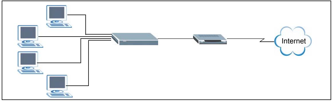
Figure 1 ZyXEL Device for Internet Sharing
1.1.2 Wireless Network
By default, the integrated wireless feature is enabled on the ZyXEL Device that allows you to set up a wireless network in your home or small office. Once connected, wireless clients can access network resources (such as Internet access, printers or servers).
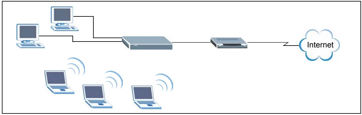
Figure 2 Wireless Network Setup Using the ZyXEL Device
You can also configure firewall on the ZyXEL Device for secure Internet access. When the firewall is on, all incoming traffic from the Internet to your network is blocked unless it is initiated from your network. This means that probes from the outside to your network are not allowed, but you can safely browse the Internet and download files for example.
Use web filters to block access to web site addresses that you specify. You can define time periods and days during which web filters are enabled and include or exclude particular computers on your network from content filtering. For example, you could block access to certain web sites for the kids.
1.2 Good Habits for Managing Your ZyXEL Device
Here are some things you should do regularly.
- Change your password.
- Back up your configuration (and make sure you know how to reload it).
1.2.1 LEDs
The following figure shows the LEDs on the ZyXEL Device.

Figure 3 Front Panel
The following table describes the LEDs.
Table 1 Front Panel LEDs
| LED | COLOR | STATUS | DESCRIPTION |
| PWR | Off | The ZyXEL Device is not receiving power. | |
| Green | On | The ZyXEL Device is receiving power and ready. | |
| Blinking | The ZyXEL Device is resetting to the factory defaults. | ||
| LAN1..4 | Off | No device is connected to this port. | |
| Green | On | An Ethernet device is connected to this port. | |
| Blinking | The ZyXEL Device is sending/receiving data on this port. | ||
| WAN | Off | The WAN connection is not ready, or has failed. | |
| Green | On | The ZyXEL Device has a successful WAN connection for Internet access. | |
| Blinking | The ZyXEL Device is sending/receiving data over the WAN port. | ||
| WLAN | Off | The WLAN is disabled. | |
| Amber | On | Pre-N WLAN is enabled on the ZyXEL Device. | |
| Blinking | The ZyXEL Device is sending/receiving data over the pre-N WLAN. | ||
| Green | On | IEEE 802.11b/g WLAN is enabled on the ZyXEL Device. | |
| Blinking | The ZyXEL Device is sending/receiving data over the IEEE 802.11b/g WLAN. | ||
| USB | Off | The USB port is not in use | |
| Green | Blinking (3 Times) | Windows Connect Now setup is successful. | |
| Blinking (Continuous) | Windows Connect Now setup is not successful. |
1.3 Rear Panel
The following figure shows the rear panel.
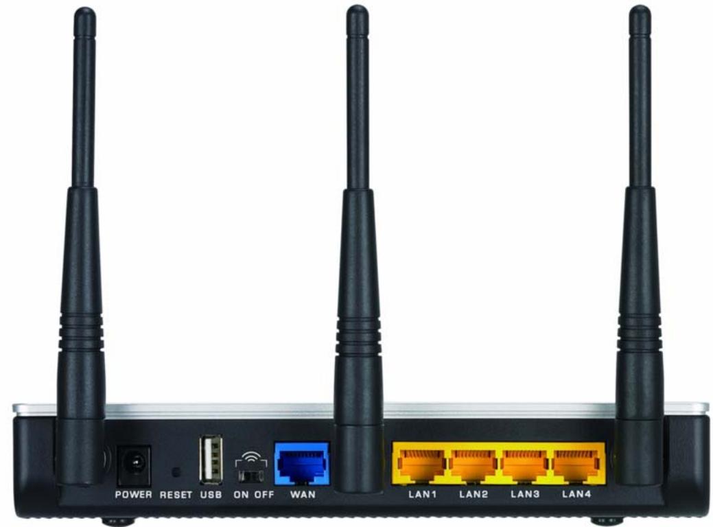
Figure 4 Rear Panel
The following table describes the labels on the rear panel.
Table 2 Rear Panel
| LABEL | DESCRIPTION |
| POWER | Use the included power adaptor to connect this port to an appropriate power source. |
| RESET | You only need to use this button when you have changed the device login password and have now forgotten it. Note: Using the RESET button erases all custom settings and resets the device back to the factory defaults. Use a pointed object to press this button in for more than 10 seconds and release. The device resets to the factory default settings and automatically restarts. |
| USB | Connect a USB storage device to this port to configure wireless settings on wireless clients using the Windows Wireless Now feature (currently available on Windows XP with service pack 2). Refer to Section 6.3 on page 68 for more information. |
| ON OFF | Use this switch to enable (ON) or disable (OFF) the wireless LAN on the device. |
| WAN | Use the Ethernet cable that comes with your DSL/cable modem to connect to the Ethernet port on the DSL/cable modem. |
| LAN 1..4 | Use Ethernet cables to connect up to four computers to the ZyXEL Device. To connect more than four computers, use a switch. |
CHAPTER 2
The Web Configurator
This chapter introduces the main features and applications of your ZyXEL Device.
2.1 Introduction
The web configurator is an HTML-based management interface that allows easy device setup and management via Internet browser. Use Internet Explorer 6.0 and later or Netscape Navigator 7.0 and later versions. The recommended screen resolution is 1024 by 768 pixels.
In order to use the web configurator you need to allow:
- Web browser pop-up windows from your device. Web pop-up blocking is enabled by default in Windows XP SP (Service Pack) 2.
JavaScript (enabled by default). - Java permissions (enabled by default).
Note: By default, you can only access the web configurator through a LAN port. To access via the WAN, enable remote management in the Admin screen.
2.2 Login
Follow the steps below to log into the web configurator.
1 Start your web browser.
2 Type "http://" and the IP address of the ZyXEL Device (for example, the default is 192.168.1.1) in the Location or Address field. Press [ENTER].
3 The login screen appears. Select admin in the User Name field to log in as an administrator.
4 Enter the associated password. The default administrative login password is "1234"
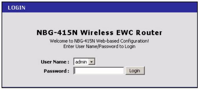
Figure 5 Web Configurator: Login
5 Click Login to view the first web configurator screen. The Device Information screen is the first screen that displays when you access the web configurator.
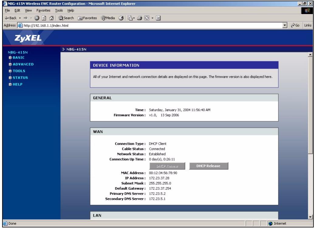
Figure 6 Web Configurator: Main Screen
Note: The management session automatically times out after five minutes of inactivity. Simply log back into the ZyXEL Device if this happens to you.
The following table lists the various web configurator screens.
Table 3 Web Configurator: Menus
| BASIC | ADVANCED | TOOLS | STATUS | HELP |
| Start | Game Hosting | Admin | Device Info | Menu |
| WAN | Virtual Server | Time | Wireless | Basic |
| LAN | Applications | Logs | Advanced | |
| Wireless | StreamEngine | System | Statistics | Tools |
| Routing | Firmware | Status | ||
| Access Control | DDNS | Glossary | ||
| Web Filter | Ping | |||
| MAC Filter | ||||
| Firewall | ||||
| Inbound Filter | ||||
| Wireless | ||||
| Schedules |
2.3 Web Configurator Screen Buttons
The following table describes the common buttons in the web configurator.
Table 4 Web Configurator: Common Screen Buttons
| BUTTON | DESCRIPTION |
| Save Settings | Click this button to save all changes permanently to the device. |
| Discard Settings | Click this button to discard all changes. Note: All unsaved changes in all screens will be lost. |
| Save | Click this button to save the changes of a configuration screen for the current session. |
| Clear | Click this button to start configuring a screen again. |
| Click this button to change the settings of the selected rule. | |
| Click this button to remove the selected rule. |
2.4 Saving Configuration Changes
Note: You must save the current configuration in the ZyXEL Device to make the changes take effect.
Do NOT turn off the ZyXEL Device during the updating process, as it may corrupt the firmware and make your ZyXEL Device unusable.
Follow the steps below to save configuration changes.
1 Click Save Settings in a configuration screen.
2 A Success screen displays.
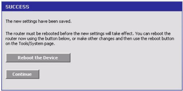
Figure 7 Save Settings: Success
- Click Reboot the Device to restart the ZyXEL Device and make the changes take effect. Wait before the ZyXEL Device finishes rebooting before accessing the web configurator again.
- Alternatively, click Continue to return to the previous configuration screen.
2.5 Changing Your Password
It is highly recommended that you periodically change the password for the login accounts for security reasons. Click Tools > Admin to display the screen as shown next.
Configure the password fields for the admin and user accounts then click Save Settings and reboot the device to make the changes take effect.
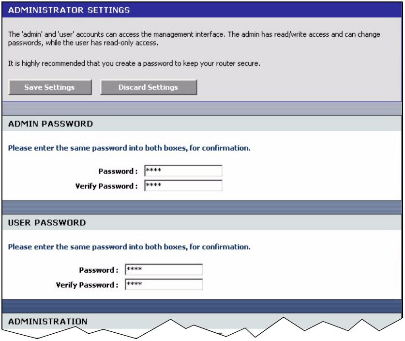
Figure 8 Change Password
The following table describes the related fields in this screen.
Table 5 Change Password
| LABEL | DESCRIPTION |
| Admin Password | |
| Password | Type the new password in this field. |
| Verify Password | Type the new password again in this field. |
| User Password | |
| Password | Type the new password in this field. |
| Verify Password | Type the new password again in this field. |
2.5.1 Resetting the ZyXEL Device
If you forget your administrative login password or cannot access the web configurator, you will need to use the RESET button to reload the factory-default configuration file. This means that you will lose all configurations that you had previously and the password will be reset to "1234".
2.5.1.1 Using the Reset Button
1 Use a pointed object to press the RESET button for more than 10 seconds and then release.
2 Wait until the WAN, LAN and WLAN LEDs turn off and blink. This indicates that the ZyXEL Device has reset the configuration to the factory defaults.
3 Wait until the ZyXEL Device finishes restarting before accessing it again.
CHAPTER 3 Basic
This chapter describes the Basic screens you use to configure the wizard, LAN, WAN and WLAN settings.
3.1 Setup Wizard
You can use the wizard screens to configure the ZyXEL Device for Internet access and secure wireless connection.
Click Basic > Start to display the main Wizard screen. Use the wizard screens to configure basic settings for Internet access and wireless connection.
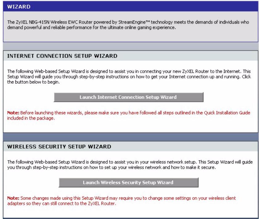
Figure 9 Basic: Start (Wizard)
3.1.1 Internet Connection Setup Wizard
Follow the steps below to use the wizard setup screens to configure the ZyXEL Device for Internet access with the information given to you by your ISP.
Note: See the advanced menu chapters for background information on these fields.
1 Click START > WIZARD > Launch Internet Connection Setup Wizard to display the first wizard screen. This screen states whether the ZyXEL Device can automatically detect the connection type and access the Internet. If Internet connection is not available, this screen outlines the steps to set up your ZyXEL Device. Click Next to continue.
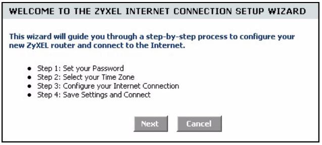
Figure 10 Internet Connection Setup Wizard: Welcome
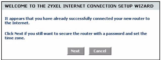
Figure 11 Internet Connection Setup Wizard: Welcome (Internet Connection Detected)
2 The second wizard screen prompts you to change the login password. Enter a new password in the Password field and retype the password in Verify Password field to verify. Click Next.
Note: Passwords are case sensitive.
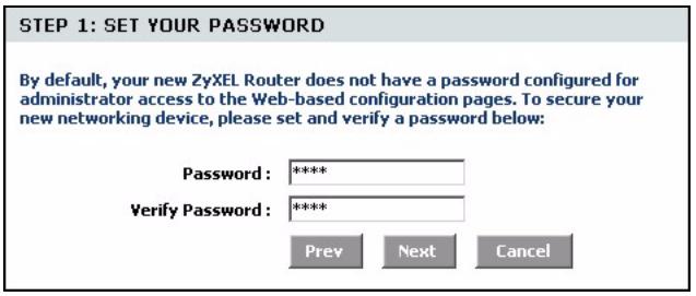
Figure 12 Internet Connection Setup Wizard: Step 1
3 Select the time zone for your geographical location. For example, if you are in California, select (GMT-08:00) Pacific Time (US/Canada), Tijuana. Click Next.
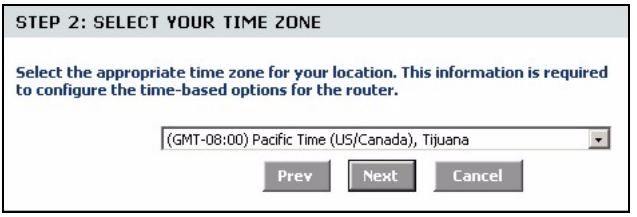
Figure 13 Internet Connection Setup Wizard: Step 2
4 Select your Internet connection type and click Next to continue.
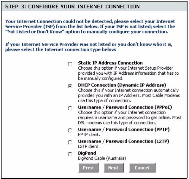
Figure 14 Internet Connection Setup Wizard: Step 3
5 The next wizard screen varies depending on the connection type you have selected. Configure the fields with the information provided by your ISP and click Next.
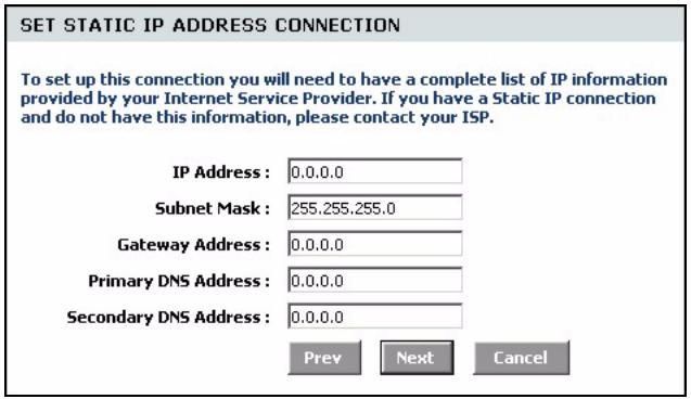
Figure 15 Internet Connection Setup Wizard: Step 3 (Static IP Address)
The following table describes the related fields in this screen.
Table 6 Internet Connection Setup Wizard: Step 3 (Dynamic IP Address)
| field | description |
| IP Address | Enter the IP address that your ISP gave you. This should be a static, public IP address. |
| Subnet Mask | Enter the subnet mask for the IP address. |
| Gateway Address | Enter the IP address of the router through which this WAN connection will send traffic (the default gateway). |
| Primary/Secondary DNS Address | DNS (Domain Name System) is for mapping a domain name to its corresponding IP address and vice versa. The DNS server is extremely important because without it, you must know the IP address of a computer before you can access it. The ZyXEL Device uses a system DNS server (in the order you specify here) to resolve domain names for VPN, DDNS and the time server. Enter the DNS server IP addresses. |
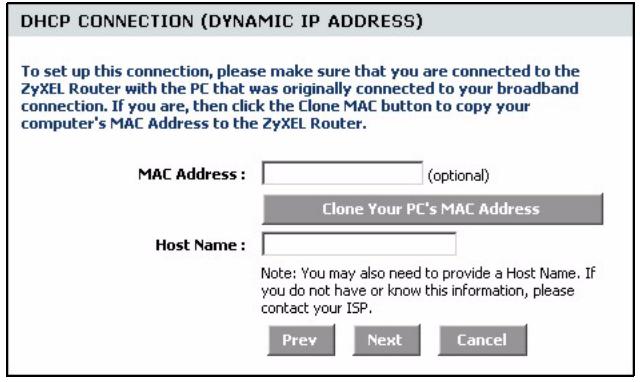
Figure 16 Internet Connection Setup Wizard: Step 3 (Dynamic IP Address)
The following table describes the related fields in this screen.
Table 7 Internet Connection Setup Wizard: Step 3 (Dynamic IP Address)
| FIELD | DESCRIPTION |
| MAC Address | If required by your ISP, enter your computer MAC address in the MAC Address field or click Clone Your PC's MAC Address to copy the MAC address of the computer connecting to your ISP onto the ZyXEL Device. |
| Host Name | If a host name is necessary for a successful Internet connection, enter it in the Host Name field. Click Next to continue. |
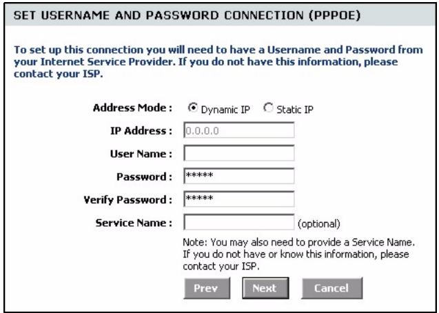
Figure 17 Internet Connection Setup Wizard: Step 3 (PPPoE)
The following table describes the related fields in this screen.
Table 8 Internet Connection Setup Wizard: Step 3 (PPPoE)
| FIELD | DESCRIPTION |
| Address Mode | Select Dynamic IP If your ISP did not assign you a fixed IP address. This is the default selection. Select Static IP If your ISP assigned a fixed IP address. The set the following fields. |
| IP Address | This field is applicable if you select Static IP in the Address Mode field. Enter the IP address that your ISP gave you. This should be a static, public IP address. |
| User Name | Type the user name given to you by your ISP. You can use alphanumeric and - @./ characters, and it can be up to 31 characters long. |
| Password | Type the password associated with the user name above. Use up to 64 ASCII characters except the [, ] and ?. This field can be blank. |
| Verify Password | Type your password again for confirmation. |
| Service Name | Type the PPPoE service name given to you by your ISP. PPPoE uses a service name to identify and reach the PPPoE server. You can use alphanumeric and - @./ characters, and it can be up to 64 characters long. |
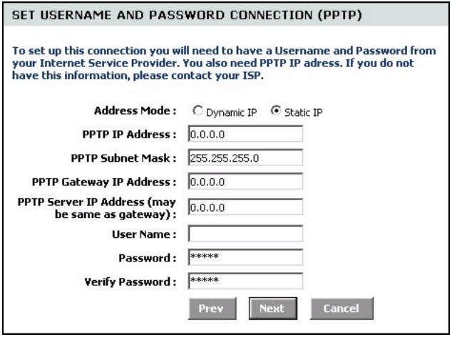
Figure 18 Internet Connection Setup Wizard: Step 3 (PPTP)
The following table describes the related fields in this screen.
Table 9 Internet Connection Setup Wizard: Step 3 (PPTP)
| FIELD | DESCRIPTION |
| Address Mode | Select Dynamic IP If your ISP did not assign you a fixed IP address. This is the default selection. Select Static IP If your ISP assigned a fixed IP address. The set the following fields. |
| PPTP IP Address | This field is applicable if you select Static IP in the Address Mode field. Enter the IP address that your ISP gave you. This should be a static, public IP address. |
| PPTP Subnet Mask | This field is applicable if you select Static IP in the Address Mode field. Enter the subnet mask for the IP address. |
| PPTP Gateway IP Address | This field is applicable if you select Static IP in the Address Mode field. Enter the IP address of the router through which this WAN connection will send traffic (the default gateway). |
Table 9 Internet Connection Setup Wizard: Step 3 (PPTP)
| FIELD | DESCRIPTION |
| PPTP Server IP Address (may be same as gateway) | Type the IP address of the PPTP server. |
| UserID | Type the user name given to you by your ISP. You can use alphanumeric and -@@/. characters, and it can be up to 31 characters long. |
| Password | Type the password associated with the user name above. Use up to 64 ASCII characters except the [, ] and ?. This field can be blank. |
| Verify Password | Type your password again for confirmation. |
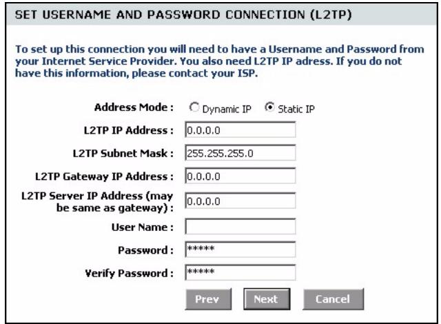
Figure 19 Internet Connection Setup Wizard: Step 3 (L2TP)
The following table describes the related fields in this screen.
Table 10 Internet Connection Setup Wizard: Step 3 (L2TP)
| FIELD | DESCRIPTION |
| Address Mode | Select Dynamic IP If your ISP did not assign you a fixed IP address. This is the default selection. Select Static IP If your ISP assigned a fixed IP address. The set the following fields. |
| L2TP IP Address | This field is applicable if you select Static IP in the Address Mode field. Enter the IP address that your ISP gave you. This should be a static, public IP address. |
| L2TP Subnet Mask | This field is applicable if you select Static IP in the Address Mode field. Enter the subnet mask for the IP address. |
| L2TP Gateway IP Address | This field is applicable if you select Static IP in the Address Mode field. Enter the IP address of the router through which this WAN connection will send traffic (the default gateway). |
| L2TP Server IP Address (may be same as gateway) | Type the IP address of the L2TP server. |
| User Name | Type the user name given to you by your ISP. You can use alphanumeric and -@@characters, and it can be up to 31 characters long. |
| Password | Type the password associated with the user name above. Use up to 64 ASCII characters except the [, ] and ?. This field can be blank. |
| Verify Password | Type your password again for confirmation. |
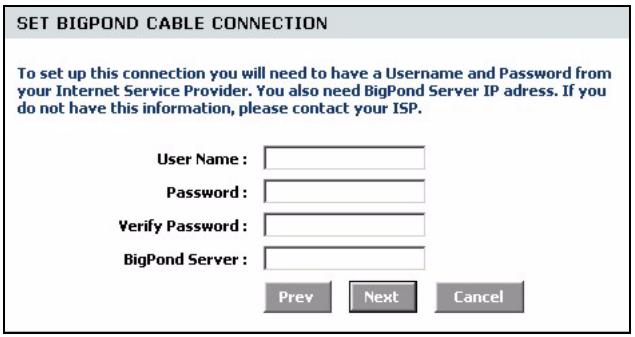
Figure 20 Internet Connection Setup Wizard: Step 3 (BigPond)
The following table describes the related fields in this screen.
Table 11 Internet Connection Setup Wizard: Step 3 (BigPond)
| FIELD | DESCRIPTION |
| User Name | Type the user name given to you by your ISP. You can use alphanumeric and - @$. / characters, and it can be up to 31 characters long. |
| Password | Type the password associated with the user name above. Use up to 64 ASCII characters except the [, ] and ? . This field can be blank. |
| Verify Password | Type your password again for confirmation. |
| BigPond Server | Type the IP address of the BigPond server. |
6 In the las wizard screen, click Connect to save the settings to the ZyXEL Device.

Figure 21 Internet Connection Setup Wizard: Setup Complete
7 Click Reboot the Device to restart the ZyXEL Device and make the changes take effect.
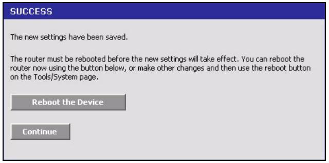
Figure 22 Internet Connection Setup Wizard: Success
8 Wait until the ZyXEL Device finishes rebooting before accessing it again.
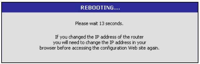
Figure 23 Internet Connection Setup Wizard: Rebooting
9 Test your Internet connection. Launch your web browser and enter any web site address for example, http://www.zyxel.com).
3.2 Wireless Security Setup Wizard
Follow the steps below to use the wizard setup screens to configure a wireless LAN and wireless security setting on the ZyXEL Device.
Note: See the advanced menu chapters for background information on these fields.
1 Click START > WIZARD > Launch Wireless Security Setup Wizard to display the first wizard screen. This screen outlines the steps to set up your ZyXEL Device. Click Next to continue.
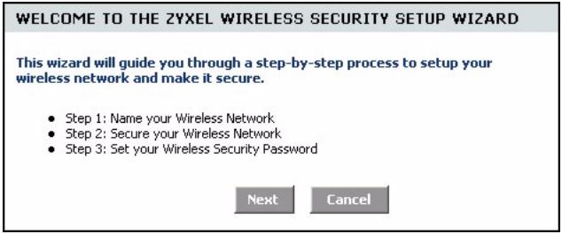
Figure 24 Wireless Security Setup Wizard
2 In the Wireless Network Name field, enter a descriptive name for identifying the wireless network. To connect to this wireless network, wireless clients must associate to this ID. Click Next.
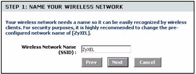
Figure 25 Wireless Security Setup Wizard: Network Name
3 Follow the on-screen instruction and select a wireless security mode. Click Next.
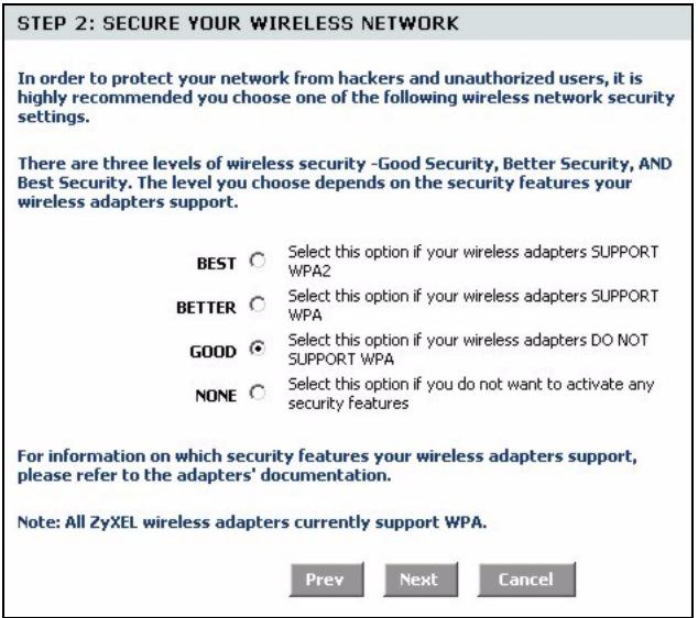
Figure 26 Wireless Security Setup Wizard: Security
4 The next screen displays if you enable a wireless security mode. Follow the on-screen instruction. Enter a WEP key if you select GOOD security level. If you select BETTER or BEST security level, enter a password that the ZyXEL Device uses to generate a unique wireless secret key. Click Next.
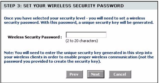
Figure 27 Wireless Security Setup Wizard: Security Key
5 Check your wireless LAN settings in this screen and click Save to save the settings to the ZyXEL Device.
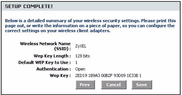
Figure 28 Wireless Security Setup Wizard: Finish
6 Click Reboot the Device to restart the ZyXEL Device and make the changes take effect.
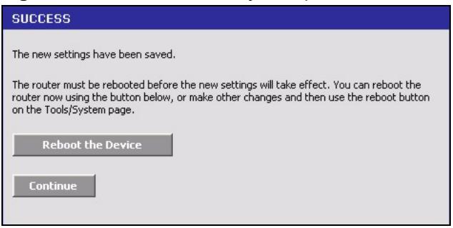
Figure 29 Wireless Security Setup Wizard: Success
7 Wait until the ZyXEL Device finishes rebooting before accessing it again.
Figure 30 Wireless Security Setup Wizard: Rebooting
8 Test your wireless connection. On a wireless client, associate to the wireless network on the ZyXEL Device (the default network name is "ZyXEL"). See the documentation that comes with the wireless client for more information.
CHAPTER 4 WAN
This chapter introduces you how to configure the WAN using the advanced configuration screen for Internet access.
4.1 WAN Overview
You can use the advanced WAN configuration screen to configure the WAN port for Internet access. Select the Internet access mode (Static IP, Dynamic IP, PPPoE, PPTP and L2TP) your ISP uses on the ZyXEL Device.
4.1.1 WAN IP Address Assignment
Every computer on the Internet must have a unique IP address. If your networks are isolated from the Internet, for instance, only between your two branch offices, you can assign any IP addresses to the hosts without problems. However, the Internet Assigned Numbers Authority (IANA) has reserved the following three blocks of IP addresses specifically for private networks.
Table 12 Private IP Address Ranges
| 10.0.0.0 | - | 10.255.255.255 |
| 172.16.0.0 | - | 172.31.255.255 |
| 192.168.0.0 | - | 192.168.255.255 |
You can obtain your IP address from the IANA, from an ISP or have it assigned by a private network. If you belong to a small organization and your Internet access is through an ISP, the ISP can provide you with the Internet addresses for your local networks. On the other hand, if you are part of a much larger organization, you should consult your network administrator for the appropriate IP addresses.
Note: Regardless of your particular situation, do not create an arbitrary IP address; always follow the guidelines above. For more information on address assignment, please refer to RFC 1597, Address Allocation for Private Internets and RFC 1466, Guidelines for Management of IP Address Space.
4.1.2 DNS Server Address Assignment
Use DNS (Domain Name System) to map a domain name to its corresponding IP address and vice versa, for instance, the IP address of www.zyxel.com is 204.217.0.2. The DNS server is extremely important because without it, you must know the IP address of a computer before you can access it.
The ZyXEL Device can get the DNS server addresses in the following ways.
1 The ISP tells you the DNS server addresses, usually in the form of an information sheet, when you sign up. If your ISP gives you DNS server addresses, manually enter them in the DNS server fields.
2 If your ISP dynamically assigns the DNS server IP addresses (along with the ZyXEL Device's WAN IP address), set the DNS server fields to get the DNS server address from the ISP.
3 You can manually enter the IP addresses of other DNS servers. These servers can be public or private. A DNS server could even be behind a remote IPSec router.
4.2 WAN Configuration
To display the advanced WAN configuration screen, click BASIC > WAN. Fields in this screen vary depending on the option you select in the WAN Mode field.
4.2.1 WAN Connection: Dynamic IP
Select Dynamic IP in the WAN screen when your ISP gives you a fixed public IP address.
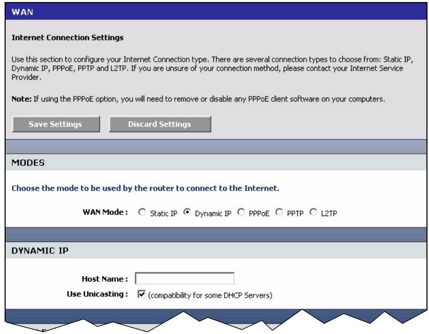
Figure 31 Basic: WAN: Dynamic IP
The following table describes the fields in this screen.
Table 13 Basic: WAN: Dynamic IP
| LABEL | DESCRIPTION |
| MODES | |
| WAN | Select Dynamic IP if you are not given a fixed public IP address and the account information (such as the user name and password). |
| Dynamic IP | |
| Hostname | This field is optional. Enter your computer's hostname which the ISP checks before Internet access is allowed. |
| Use Unicasting | Select this option If your ZyXEL Device is unable to obtain a WAN IP address from the ISP. This allows the ZyXEL Device to accept unicast DHCP responses from the DHCP server instead of broadcast DHCP responses. |
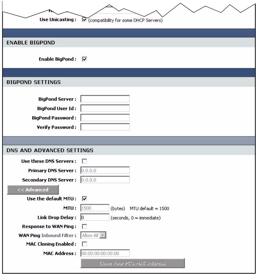
| Enable BigPond | Select Enable BigPond if you subscribe to Internet service from BigPond in Australia. Then configure the fields below with the information provided. |
| BigPond Settings | |
| BigPond Server | Type the IP address of the BigPond server. |
| BigPond User ID | Type the user name given to you by your ISP. You can use alphanumeric and -@@ characters, and it can be up to 31 characters long. |
| BigPondPassword | Type the password associated with the user name above. Use up to 64 ASCII characters except [, ] and ? . This field can be blank. |
| VerifyPassword | Type your password again for confirmation. |
| DNS Settings | |
| Use these DNS Servers | Select this option to manually enter the DNS server IP address(es) in the field(s) provided. |
| Primary/SecondaryDNS Server | Enter the IP address (provided by your ISP) of the DNS server in dotted decimal notation. |
| Advanced >> | Click Advanced >> to display more WAN configuration fields. |
| << Advanced | Click << Advanced to hide the advanced WAN configuration fields. |
| Use the Default MTU | Maximum Transmission Unit (MTU) is a parameter that determines the largest packet size (in bytes) that the ZyXEL Device will send to the WAN. If LAN devices send larger packets, the ZyXEL Device will break them into smaller packets. Ideally, you should set this to match the MTU of the connection to your ISP. Select this option to use the default MTU. Clear this checkbox to manually enter an MTU size below. |
| MTU | Enter the MTU size (between 256 and 2296). Typical values are 1500 bytes for an Ethernet connection and 1492 bytes for a PPPoE connection. Make sure the MTU size matches the ISP's network or Internet connection may fail. |
| Link Drop Delay | |
| MAC Cloning Enabled | Select this option to set the ZyXEL Device to copy the MAC address of your computer. |
| MAC Address | Enter the IP address of the computer on the LAN whose MAC you are cloning. It is recommended that you clone the MAC address prior to hooking up the WAN port. |
| Clone Your PC's MAC Address | Click Clone Your PC's MAC Address to have the ZyXEL Device automatically copy the MAC address from your computer. |
4.2.2 WAN Configuration: Static IP
Select Dynamic IP in the WAN screen when your ISP gives you a fixed public IP address.
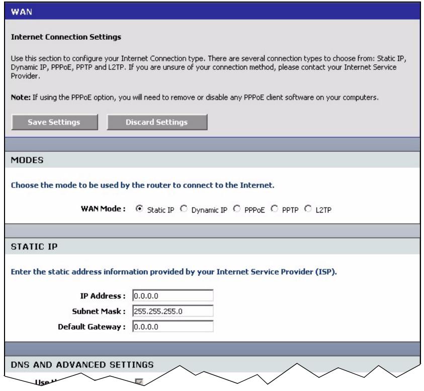
Figure 32 Basic: WAN: Static IP
The following table describes the related fields in this screen.
Table 14 Basic: WAN: Static IP
| LABEL | DESCRIPTION |
| MODES | |
| WAN | Select Static IP if your ISP gives you a fixed public IP address. |
| STATIC IP | |
| IP Address | Enter the WAN IP address exactly as given by your ISP in dotted decimal notation. |
| Subnet Mask | Enter the IP subnet mask as given by your ISP in dotted decimal notation. |
| Default Gateway | Enter the gateway IP address as given by your ISP in dotted decimal notation. |
Refer to Table 13 on page 44 for other field descriptions.
4.2.3 WAN Configuration: PPPoE
If your ISP uses the PPPoE (Point-to-Point Protocol over Ethernet) protocol for Internet access, select PPPoE in the WAN Mode field.
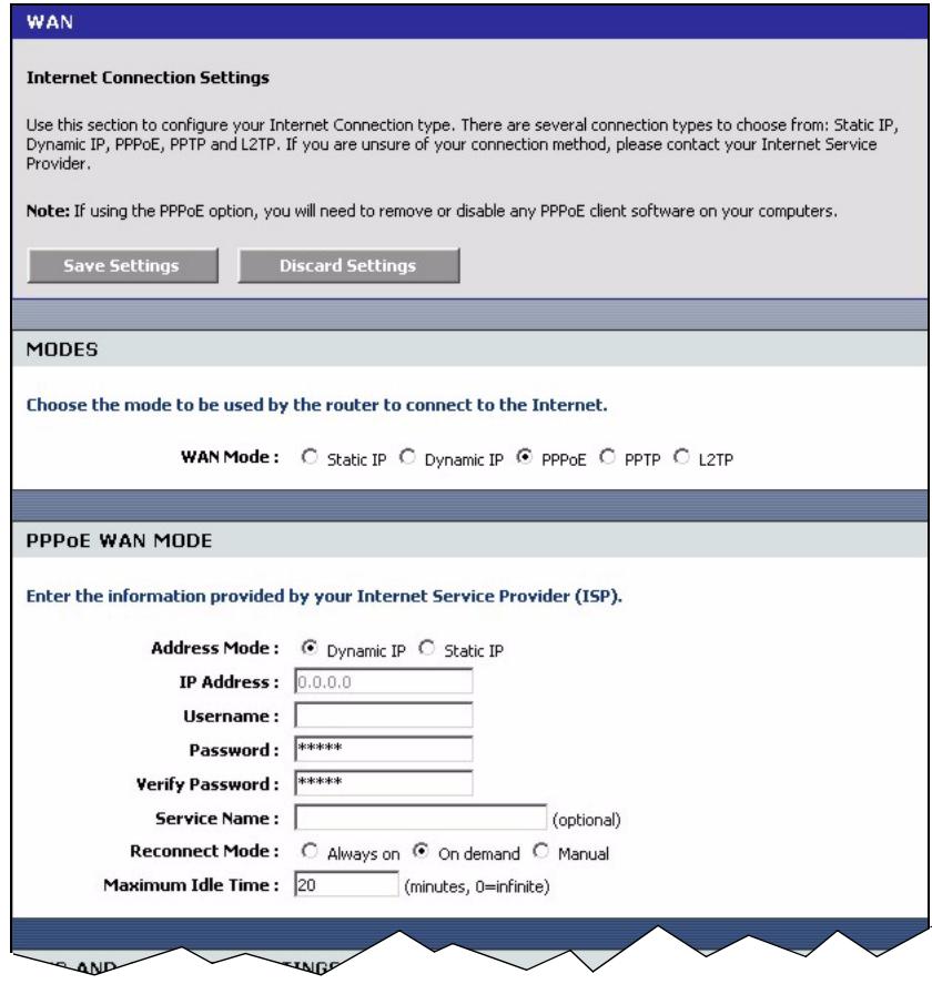
Figure 33 Basic: WAN: PPPoE
The following table describes the related fields in this screen.
Table 15 Basic: WAN: PPPoE
| LABEL | DESCRIPTION |
| MODES | |
| WAN | Select PPPoE if your ISP gives you Internet access account information (such as the username and password). |
| PPPoE WAN MODE | |
| Address Mode | Select Dynamic IP If your ISP did not assign you a fixed IP address. This is the default selection. Select Static IP If your ISP assigned a fixed IP address. The set the following fields. |
| IP Address | This field is applicable if you select Static IP in the Address Mode field. Enter the IP address that your ISP gave you. This should be a static, public IP address. |
| User Name | Type the user name given to you by your ISP. You can use alphanumeric and - @. / characters, and it can be up to 31 characters long. |
| Password | Type the password associated with the user name above. Use up to 64 ASCII characters except the [, ] and ? . This field can be blank. |
| Verify Password | Type your password again for confirmation. |
| Service Name | Type the PPPoE service name given to you by your ISP. PPPoE uses a service name to identify and reach the PPPoE server. You can use alphanumeric and - @. / characters, and it can be up to 64 characters long. |
| Reconnect Mode | Specify how you want to re-establish an Internet connection after the idle timeout. Select Always On when you want your connection up all the time. The ZyXEL Device will try to bring up the connection automatically if it is disconnected. Select On Demand when you don't want the connection up all the time and specify an idle time-out in the Maximum Idle Timeout field. Select Manual when you want to manually re-establish the connection if it is disconnected. |
| Maximum Idle Time | This value specifies the time in seconds that elapses before the ZyXEL Device automatically disconnects from the PPPoE server. |
Refer to Table 13 on page 44 for other field descriptions.
4.2.4 WAN Connection: PPTP
If your ISP uses PPTP protocol for Internet access, select PPTP in the WAN Mode field.
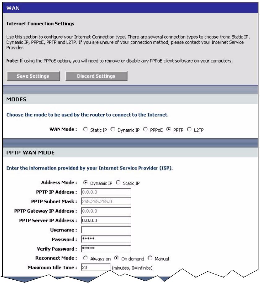
Figure 34 Basic: WAN: PPTP
The following table describes the related fields in this screen.
Table 16 Basic: WAN: PPTP
| LABEL | DESCRIPTION |
| MODES | |
| WAN | Select PPTP if your ISP gives you Internet access account information (such as the username and password). |
| PPTP WAN MODE | |
| Address Mode | Select Dynamic IP If your ISP did not assign you a fixed IP address. This is the default selection. Select Static IP If your ISP assigned a fixed IP address. The set the following fields. |
| PPTP IP Address | This field is applicable if you select Static IP in the Address Mode field. Enter the IP address that your ISP gave you. This should be a static, public IP address. |
| PPTP Subnet Mask | This field is applicable if you select Static IP in the Address Mode field. Enter the subnet mask for the IP address. |
| PPTP Gateway IP Address | This field is applicable if you select Static IP in the Address Mode field. Enter the IP address of the router through which this WAN connection will send traffic (the default gateway). |
| PPTP Server IP Address (may be same as gateway) | Type the IP address of the PPTP server. |
| User Name | Type the user name given to you by your ISP. You can use alphanumeric and -@@ characters, and it can be up to 31 characters long. |
| Password | Type the password associated with the user name above. Use up to 64 ASCII characters except the [, ] and ?: This field can be blank. |
| Verify Password | Type your password again for confirmation. |
| Reconnect Mode | Specify how you want to re-establish an Internet connection after the idle timeout. Select Always On when you want your connection up all the time. The ZyXEL Device will try to bring up the connection automatically if it is disconnected. Select On Demand when you don't want the connection up all the time and specify an idle time-out in the Maximum Idle Timeout field. Select Manual when you want to manually re-establish the connection if it is disconnected. |
| Maximum Idle Time | This value specifies the time in seconds that elapses before the ZyXEL Device automatically disconnects from the PPPoE server. |
4.2.5 WAN Connection: L2TP
If your ISP uses L2TP protocol for Internet access, select L2TP in the WAN Mode field.
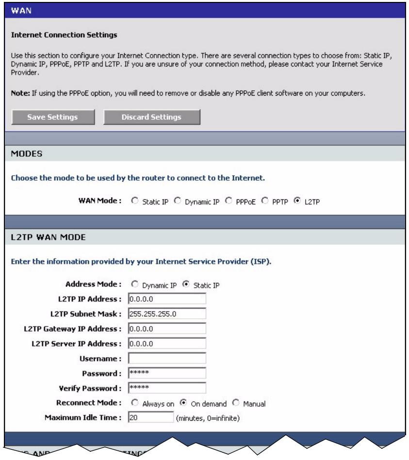
Figure 35 Basic: WAN: L2TP
The following table describes the related fields in this screen.
Table 17 Basic: WAN: L2TP
| LABEL | DESCRIPTION |
| MODES | |
| WAN | Select L2TP if your ISP gives you Internet access account information (such as the username and password). |
| L2TP WAN MODE | |
| Address Mode | Select Dynamic IP If your ISP did not assign you a fixed IP address. This is the default selection. Select Static IP If your ISP assigned a fixed IP address. The set the following fields. |
| L2TP IP Address | This field is applicable if you select Static IP in the Address Mode field. Enter the IP address that your ISP gave you. This should be a static, public IP address. |
| L2TP Subnet Mask | This field is applicable if you select Static IP in the Address Mode field. Enter the subnet mask for the IP address. |
| L2TP Gateway IP Address | This field is applicable if you select Static IP in the Address Mode field. Enter the IP address of the router through which this WAN connection will send traffic (the default gateway). |
| L2TP Server IP Address (may be same as gateway) | Type the IP address of the L2TP server. |
| User Name | Type the user name given to you by your ISP. You can use alphanumeric and -@@$.characters, and it can be up to 31 characters long. |
| Password | Type the password associated with the user name above. Use up to 64 ASCII characters except the [, ] and ?: This field can be blank. |
| Verify Password | Type your password again for confirmation. |
| Reconnect Mode | Specify how you want to re-establish an Internet connection after the idle timeout. Select Always On when you want your connection up all the time. The ZyXEL Device will try to bring up the connection automatically if it is disconnected. Select On Demand when you don't want the connection up all the time and specify an idle time-out in the Maximum Idle Timeout field. Select Manual when you want to manually re-establish the connection if it is disconnected. |
| Maximum Idle Time | This value specifies the time in seconds that elapses before the ZyXEL Device automatically disconnects from the L2TP server. |
4.3 Internet Connection Test
After you have configured Internet connection settings on the ZyXEL Device, test the connection. Launch a web browser and enter any web site address for example, http:// www.zyxel.com).
CHAPTER 5
LAN
5.1 Overview
Local Area Network (LAN) is a shared communication system to which many computers are attached. Use LAN screen to set the IP address and subnet mask of the LAN interface on the ZyXEL Device. You can also configure DHCP settings in the LAN screen.
Click Basic > LAN to display the configuration screen.
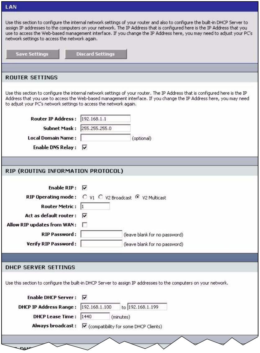
Figure 36 Basic: LAN
5.1.1 Router Settings
To set the LAN settings (such as the IP address, subnet mask) on the ZyXEL Device, configure the fields in the ROUTER SETTINGS section in the LAN screen.
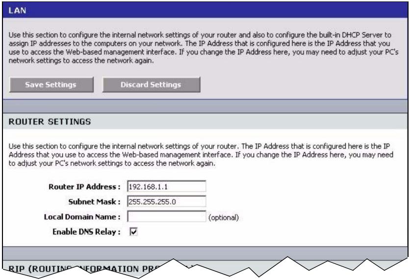
Figure 37 Basic: LAN: Router Settings
The following table describes the labels in this screen.
Table 18 Basic: LAN: Router Settings
| LABEL | DESCRIPTION |
| ROUTER SETTINGS | |
| IP Address | Type the IP address of your ZyXEL Device in dotted decimal notation. 192.168.1.1 is the factory default. Alternatively, click the right mouse button to copy and/or paste the IP address. |
| Default Subnet Mask | The subnet mask specifies the network number portion of an IP address. Your ZyXEL Device automatically calculate the subnet mask based on the IP address that you assign. Unless you are implementing subnetting, use the subnet mask computed by the ZyXEL Device. |
| Local Domain Name | This field is optional. The DHCP server on your ZyXEL Device assigns the domain name to the computer(s) on the WLAN. for the wireless network. For example, if you enter "mynetwork.net" here, and you have a wireless laptop with a computer name of chris, that laptop will be known as "chris.mynetwork.net" to other computers on the WLAN. |
| Enable DNS Relay | Select this option to set the ZyXEL Device to forward DNS requests to the ISP's DNS server. This allows computers behind the ZyXEL Device to always receive replies from a DNS server even when the ZyXEL Device obtains a different DNS server address from the ISP upon re-establishing the WAN connection. Note: You should disable DNS relay if you have set up a DNS server on the LAN in the Virtual Server screen. |
5.1.2 RIP Setup
RIP (Routing Information Protocol) allows the ZyXEL Device to exchange routing information with other routers.
RIP version controls the format and the broadcasting method of the RIP packets that the ZyXEL Device sends (it recognizes both formats when receiving). RIP version 1 (V1) is universally supported. RIP version 1 is probably adequate for most networks, unless you have an unusual network topology.
RIP version 2 carries more information in the packets.Both V2 Broadcast and V2 Multicast sends the routing data in RIP version2 format; the difference being that V2 Broadcast uses subnet broadcasting while V2 Multicast uses multicastasting.
To configure RIP settings on the ZyXEL Device, set the fields under RIP (ROUTING INFORMATION PROTOCOL) section in the LAN screen.
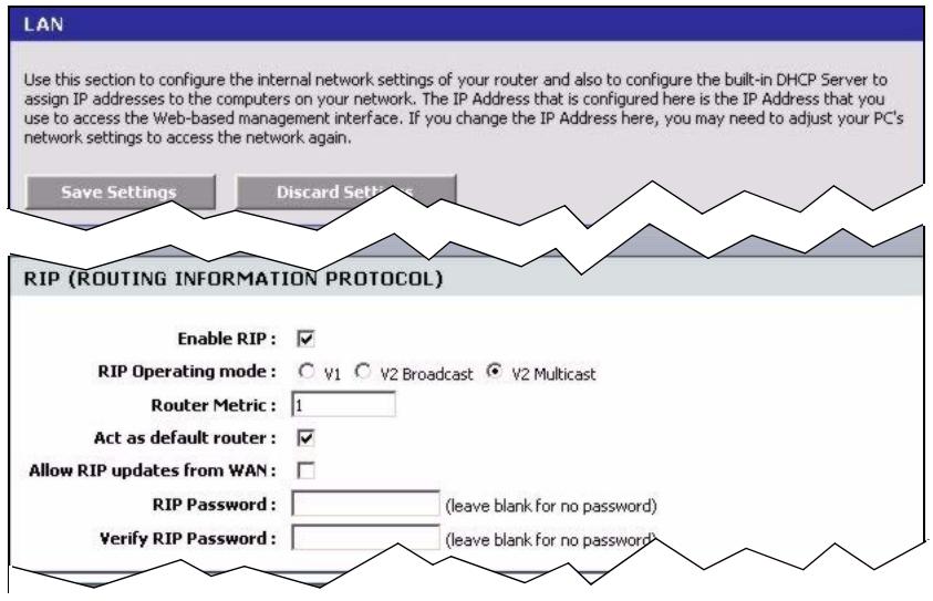
Figure 38 Basic: LAN: RIP
The following table describes the labels in this screen.
Table 19 Basic: LAN: RIP
| LABEL | DESCRIPTION |
| RIP | |
| Enable RIP | Select this option to activate RIP on the ZyXEL Device. |
| RIP Operating mode | Specify the RIP version the ZyXEL Device is to use. Select V1 if the other routers do not support RIP version 2. Select V2 Broadcast if some routers support RIP version 1 and some support RIP version 2. Select V2 Multicast if the ZyXEL Device is the only router on your network or that tall other routers support RIP version 2 only. |
| Router Metric | The metric represents the “cost” of transmission through the ZyXEL Device. IP routing uses hop count as the measurement of cost, with a minimum of 1 for directly connected networks. Enter a number that approximates the cost for this link. The number need not be precise, but it must be between 1 and 15. In practice, 2 or 3 is usually a good number. |
| Allow RIP updates from WAN | Select this option to allow the ZyXEL Device to send/receive RIP packets through the WAN port for RIP information update. It is recommended that you disable this option unless requested to do so by your ISP. |
| RIP Password | When you set the ZyXEL Device to use RIP version 2, you may enter a password to allow only authorized RIP packets to the ZyXEL Device. Enter the password if provided by your ISP. |
| Verify RIP Password | Enter the password again to confirm. |
5.1.3 DHCP Server Settings
DHCP (Dynamic Host Configuration Protocol, RFC 2131 and RFC 2132) allows individual clients to obtain TCP/IP configuration at start-up from a server. You can configure the ZyXEL Device as a DHCP server or disable it. When configured as a server, the ZyXEL Device provides the TCP/IP configuration for the DHCP client. If DHCP service is disabled, you must have another DHCP server on your LAN, or else the computer must be manually configured.
To configure DHCP settings on the ZyXEL Device, set the DHCP SERVER SETTINGS fields in the LAN screen. You can also view the list of DHCP client computers in this screen.
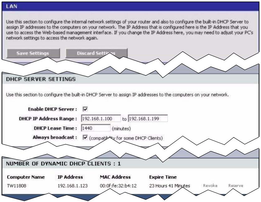
Figure 39 Basic: LAN: DHCP Server Settings
The following table describes the labels in this screen.
Table 20 Basic: LAN: DHCP Server Settings
| LABEL | DESCRIPTION |
| ENABLE | |
| Enable DHCP Server | DHCP (Dynamic Host Configuration Protocol, RFC 2131 and RFC 2132) allows individual clients (workstations) to obtain TCP/IP configuration at startup from a server. Select this option to set the ZyXEL Device to assign network information (IP address, DNS information etc.) to an Ethernet device connected to the LAN ports. Clear this check box to stop the ZyXEL Device from acting as a DHCP server. you must have another DHCP server on your LAN, or else the computer must be manually configured. |
| DHCP Address Range | The ZyXEL Device is pre-configured to provide IP addresses (ranging from 192.168.1.100 to 192.168.1.199) to DHCP clients. This configuration leaves some IP addresses (excluding the ZyXEL Device itself) in the lower and upper ranges for other server computers, for instance, servers for mail, FTP, TFTP, web, etc., that you may have. Specify the starting and end IP address for the DHCP clients. |
| DHCP Lease Time | Specify the time (in minutes) a DHCP client is allowed to use the assigned IP address from the ZyXEL Device. Once the lease time is up, the DHCP client has to renew the lease. |
| Always Broadcast | Some older DHCP client software disable DHCP broadcasting, thus some computers may not be able to obtain an IP address from the ZyXEL Device. Select this option to set the ZyXEL Device to broadcast DHCP replies. This ensures that all LAN computers can get an IP address at the cost of increased broadcast traffic on the LAN. |
| NUMBER OF DYNMAIC DHCP CLIENTS | This field displays the number of DHCP clients. |
| Computer Name | This field displays the name of the DHCP client computer. |
| MAC Address | This field displays the MAC address of the DHCP client computer. |
| IP Address | This field displays the IP address of the DHCP client computer. |
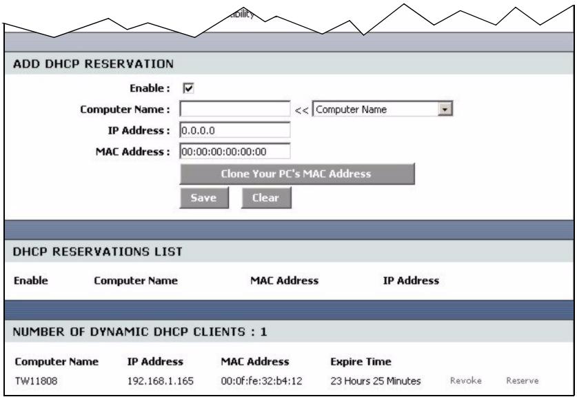
5.1.4 DHCP Reservation
DHCP reservation, also known as static DHCP, allows the ZyXEL Device to assign specific IP addresses on the LAN to specific individual computers based on their MAC addresses.
Configure DHCP Reservation settings in the LAN screen. You can also view the list of reserved IP addresses in this screen.
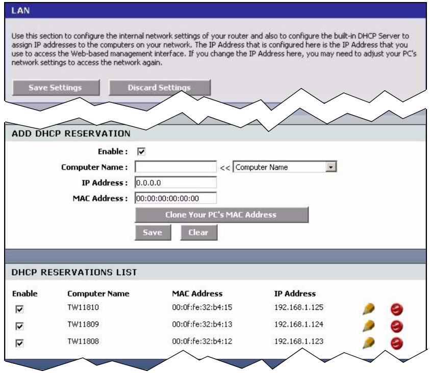
Figure 40 Basic: LAN: DHCP Reservation
The following table describes the labels in this screen.
Table 21 Basic: LAN: DHCP Reservation
| LABEL | DESCRIPTION |
| ADD DHCP RESERVATION | |
| Enable | Select this option to enable static DHCP to set the ZyXEL Device to assign one IP address on the LAN to a specific computer based on the MAC address. Clear this check box to disable this feature. |
| Computer Name | Enter the name of the DHCP client computer. This is for identification purposes. You can also select the name of the client computer currently connected to the ZyXEL Device. The ZyXEL Device automatically fills the information in the fields below. |
| IP Address | Type the IP address that you want to assign to the computer on your LAN. Alternatively, select from the list of dynamic client computer names in the drop-down list box. The ZyXEL Device automatically enters the current assigned IP address. |
| MAC Address | Type the MAC address (with colons) of a computer on your LAN. Or click Clone Your PC's MAC Address to copy the MAC address of your computer. |
| Save | Click Save to save the settings in this part of the screen. |
| Clear | Click Clear to start configuring this part of the screen again. |
| DHCP RESERVATIONS LIST | |
| Enable | Select this option to activate the static DHCP setting. |
| Computer Name | This field displays the name of the DHCP client computer. |
| MAC Address | This field displays the MAC address. |
| IP Address | This field displays the IP address of the MAC address. |
CHAPTER 6 WLAN
This chapter shows how to configure general WLAN and WLAN security settings in the WLAN screen.
6.1 General Wireless LAN Setup
Refer to Appendix B on page 128 for background information.
Configure general wireless LAN settings in the Wireless screen. Click Basic > Wireless to display the configuration screen.
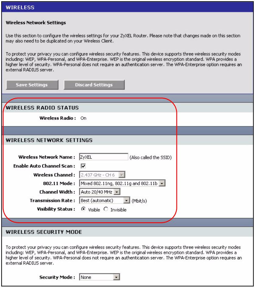
Figure 41 Basic: Wireless: General Setup
The following table describes the related labels in this screen.
Table 22 Basic: Wireless: General Setup
| LABEL | DESCRIPTION |
| WIRELESS RADIO STATUS | This field displays whether the wireless LAN feature is enabled (ON) or disabled (OFF).You can enable and disable the wireless LAN feature on the ZyXEL Device by using the wireless LAN switch at the rear panel of the ZyXEL Device. Refer to the Quick Start Guide for more information. |
| WIRELESS NETWORK SETTINGS | |
| Wireless Network Name | This is also known as the SSID (Service Set IDentification), which is a unique name to identify the ZyXEL Device in the wireless LAN. Wireless stations associating to the ZyXEL Device must have the same SSID.Enter a descriptive name of up to 32 printable characters (including spaces; alphabetic characters are case-sensitive). |
| Enable Auto Channel Scan | The radio frequency used by IEEE 802.11 wireless devices is called a channel. Select this option to set the ZyXEL Device to automatically scan for and select the optimum channel in the wireless network. |
| Wireless Channel | This field is disabled when you enable auto channel scan SELECT a channel from the drop-down list box. |
| 802.11 Mode | Select 802.11b only to have the ZyXEL Device connect to an IEEE 802.11b wireless device only and vice versa.Select Mixed 802.11b and 802.11g to have the ZyXEL Device connect to either an IEEE 802.11g or IEEE 802.11b wireless device. Select 802.11g only to have the ZyXEL Device connect to an IEEE 802.11g wireless device only and vice versa. Select 802.11ng only to have the ZyXEL Device connect to an IEEE 802.11ng wireless device only and vice versa. Select Mixed 802.11ng, 802.11g and 802.11b to have the ZyXEL Device connect to either an IEEE 802.11ng, IEEE 802.11g or IEEE 802.11b wireless device. |
| Channel Width | Specify the wireless channel bandwidth mode the ZyXEL Device is to use. Select 20 MHz to set the ZyXEL Device to transmit at up to 20 MHz to other wireless devices (including draft-N compatible wireless devices). Select this option to solve wireless connection problems in a mixed network. Select Auto 20/40 MHz to set the ZyXEL Device to automatically switch between the 20 MHz and 40 MHz operation. The ZyXEL Device will use 40 Mhz for maximum transmission speed between other draft-N compatible wireless devices. If an adjacent channel is used by an IEEE 802.11b/g device, the ZyXEL Device reverts to use 20 MHz operation. This is the recommended option. |
| Transmission Rate | Select a transmission speed from the drop-down list box. |
| Visibility Status | Select Invisible to hide the SSID in so a station cannot obtain the SSID through AP scanning. Select Visible to make the ESSID visible so a station can obtain the SSID through AP scanning. |
6.2 Wireless LAN Security
Wireless LAN security is vital to your network to protect wireless communications. If you do not enable any wireless security on your ZyXEL Device, the ZyXEL Device's wireless communications are accessible to any wireless networking device that is in the coverage area. Refer to Appendix B on page 128 for background information.
Configure the wireless LAN security using the Wireless screen. Click Basic > Wireless to display the configuration screen. This screen varies depending on the option you select in the Security Mode field.
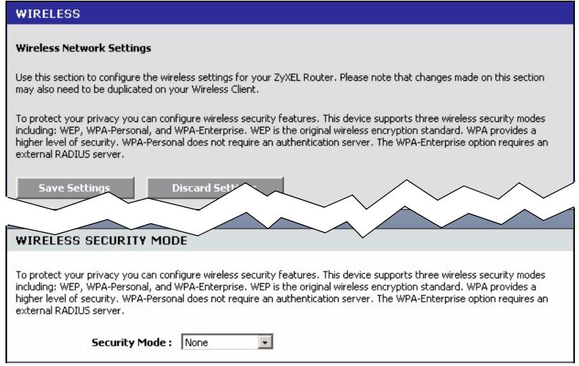
Figure 42 Basic: Wireless: WLAN Security Setup
6.2.1 WLAN Security Setup: WEP
To configure basic WEP key encryption, select WEP in the Security Mode field in the Wireless screen.
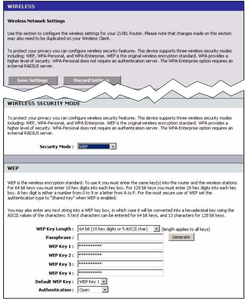
Figure 43 Basic: Wireless: WLAN Security Setup: WEP
The following table describes the related fields in this screen.
Table 23 Basic: Wireless: WLAN Security Setup: WEP
| LABEL | DESCRIPTION |
| WEP | |
| WEP Key Length | WEP (Wired Equivalent Privacy) encrypts data frames before transmitting over the wireless network. Select 64-bit (10 hex digits or 5 ASCII char) or 128-bit (26 hex digits or 13 ASCII char). |
| Key 1..4 | The WEP keys are used to encrypt data. Both the ZyXEL Device and the wireless stations must use the same WEP key for data transmission. If you want to manually set the WEP keys, enter the key in the field provided. If you chose 64-bit, then enter 10 hexadecimal characters ("0-9", "A-F"). If you chose 128-bit, then enter 26 hexadecimal characters ("0-9", "A-F"). The values for the WEP keys must be set up exactly the same on all wireless devices in the same wireless LAN. You must configure all four keys, but only one key can be used at any one time. The default key is key 1. |
| Default WEP Key | Select a default WEP key to use for data encryption. |
| Authentication | Select an authentication method. Choices are Shared Key, Open and Auto. |
6.2.2 WLAN Security Setup: WPA-Personal
If you want better WLAN security than WEP but do not have a RADIUS server on your network, select WPA-Personal in the Security Mode field in the Wireless screen.
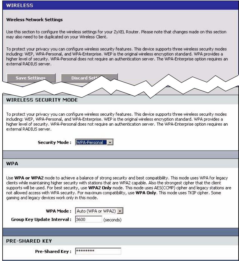
Figure 44 Basic: Wireless: WLAN Security Setup: WPA-Personal
The following table describes the related labels in this screen.
Table 24 Basic: WLAN Security Setup: WPA-Personal
| LABEL | DESCRIPTION |
| WPA | |
| WPA Mode | Specify a WPA mode. Make sure the peer device(s) is also set to use the same WPA mode. Select Auto (WPA or WPA2) to set the ZyXEL Device to use WPA2 first and then WPA if connection fails with WPA2. Select WPA Only to set the ZyXEL Device to use WPA. WPA is a older implementation than WPA2. Select WPA2 Only to set the ZyXEL Device to use WPA2 only. |
| Group Key Update Interval | This is the rate at which an AP or RADIUS server sends a new group key out to all clients. The re-keying process is the WPA equivalent of automatically changing the WEP key for an AP and all stations in a WLAN on a periodic basis. Enter an update time in seconds. |
| PRE SHARED KEY | |
| Pre-Shared Key | Type a pre-shared key from 8 to 63 case-sensitive ASCII characters (including spaces and symbols). |
6.2.3 WLAN Security Setup: WPA-Enterprise
If you want better WLAN security than WEP and have a RADIUS server on your network, select WPA-Enterprise in the Security Mode field in the Wireless screen.
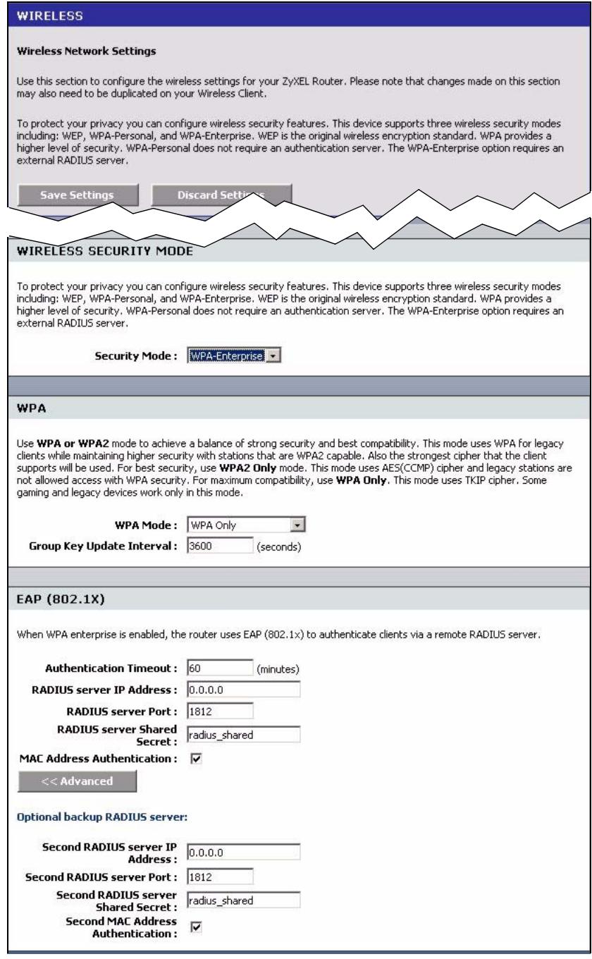
Figure 45 Basic: Wireless: WLAN Security Setup: WPA-Enterprise
The following table describes the related labels in this screen.
Table 25 Basic: WLAN Security Setup: WPA-Enterprise
| LABEL | DESCRIPTION |
| WPA | |
| WPA Mode | Specify a WPA mode. Make sure the peer device(s) is also set to use the same WPA mode. Select Auto (WPA or WPA2) to set the ZyXEL Device to use WPA2 first and then WPA if connection fails with WPA2. Select WPA Only to set the ZyXEL Device to use WPA. WPA is a older implementation than WPA2. Select WPA2 Only to set the ZyXEL Device to use WPA2 only. |
| Group Key Update Interval | This is the rate at which an AP or RADIUS server sends a new group key out to all clients. The re-keying process is the WPA equivalent of automatically changing the WEP key for an AP and all stations in a WLAN on a periodic basis. Enter an update time in seconds. |
| EAP (802.1X) | |
| Authentication Timeout | Specify how often wireless stations have to reenter user names and passwords in order to stay connected. Enter a time interval between 10 and 65535 seconds. If wireless station authentication is done using a RADIUS server, the reauthentication timer on the RADIUS server has priority. |
| RADIUS Server IP Address | Enter the IP address of the external authentication server in dotted decimal notation. |
| RADIUS Server Port | The default port of the RADIUS server for authentication is 1812. You need not change this value unless your network administrator instructs you to do so with additional information. |
| RADIUS Server Shared Secret | Enter a password (up to 31 alphanumeric characters) as the key to be shared between the external authentication server and the access points. The key is not sent over the network. This key must be the same on the external authentication server and ZyXEL Device. |
| MAC Address Authentication | Select this option to force a user to connect from the same computer when logging into the wireless network. |
| Advanced >> | Click Advanced >> to display the fields to configure the second RADIUS server. |
| << Advanced | Click << Advanced to hide the fields. |
| Optional Backup RADIUS Server | |
| Second RADIUS Server IP Address | Enter the IP address of the external authentication server in dotted decimal notation. |
| Second RADIUS Server Port | The default port of the RADIUS server for authentication is 1812. You need not change this value unless your network administrator instructs you to do so with additional information. |
| Second RADIUS Server Shared Secret | Enter a password (up to 31 alphanumeric characters) as the key to be shared between the external authentication server and the access points. The key is not sent over the network. This key must be the same on the external authentication server and ZyXEL Device. |
| Second MAC Address Authentication | Select this option to force a user to connect from the same computer when logging into the wireless network. |
6.3 Wireless Client Setup using Windows® Connect Now
With Windows® Connect Now, you can transfer wireless settings on your ZyXEL Device to a USB memory stick and then save the settings to the wireless client computer(s). This allows you to easily set up a wireless LAN. To take advantage of this feature, you need:
- A USB memory stick with at least 300K of available memory.
- Windows XP with Service Pack 2 (SP2).
Follow the steps below to set up a wireless LAN using Windows® Connect Now.
1 Click Start > Control Panel and double-click Wireless Network Setup Wizard.
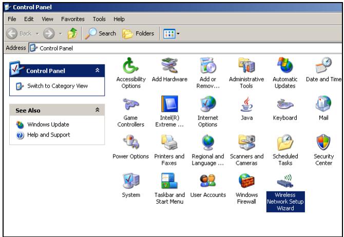
2 The first wizard screen displays. Click Next in each screen to continue.

3 Select Set up a new wireless network to configure a new wireless network.
4 In the Network name (SSID) field, specify a unique name to identify your wireless LAN.
5 Select Automatically assign a network key to have Windows create a security key.
6 Select Use WPA encryption instead of WEP for data encryption.
7 Select Use a USB Flash drive to set up a wireless network.
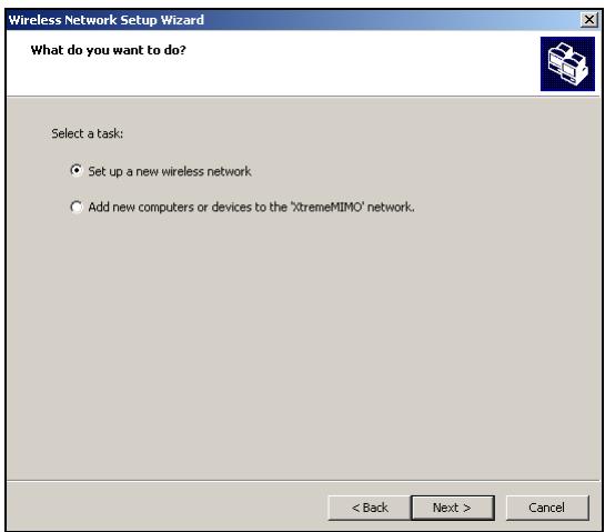
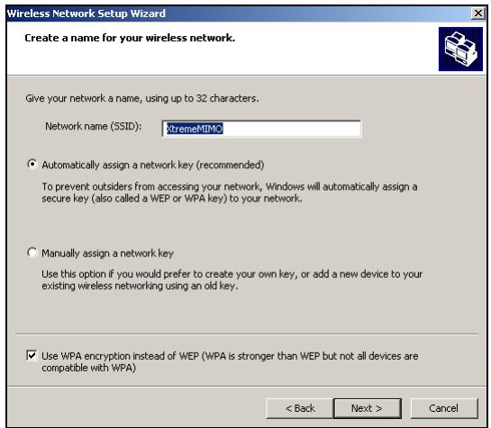
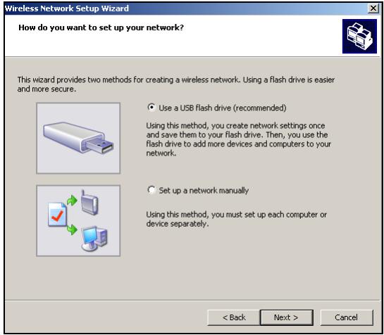
8 Connect the USB drive to your computer and specify the drive letter in the Flash drive field.
9 Follow the instructions on the screen.
10 This screen displays when you have successfully set up a secure wireless network. Click Finish.
11From a wireless computer, test your wireless LAN connection to the ZyXEL Device.
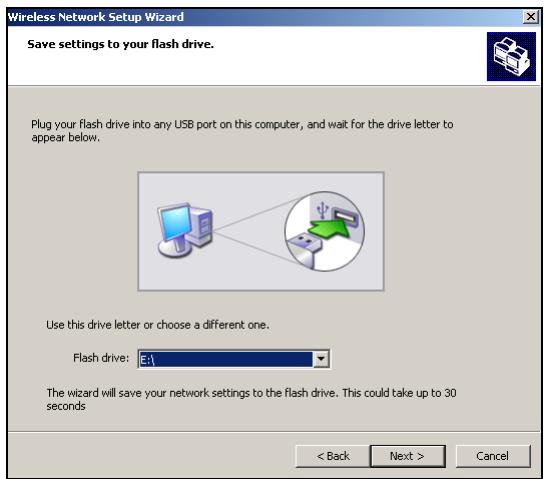
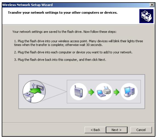
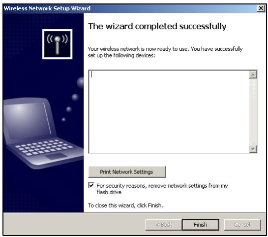
CHAPTER 7 Advanced
This chapter describes the Advanced screens you use to configure routing and security features.
7.1 Game Hosting
Some Internet applications (such as video conferencing and Internet games) require multiple connections between the clients and the server. These applications do not work through NAT-enabled networks. Your ZyXEL Device is a NAT-enabled device. In order to allow these applications to work in your network, you have to configure the ZyXEL Device to forward these applications to ports on a computer hosting the services.
To set the ZyXEL Device to forward applications to allowed ports, click Advanced > Game Hosting to display the configuration screen.
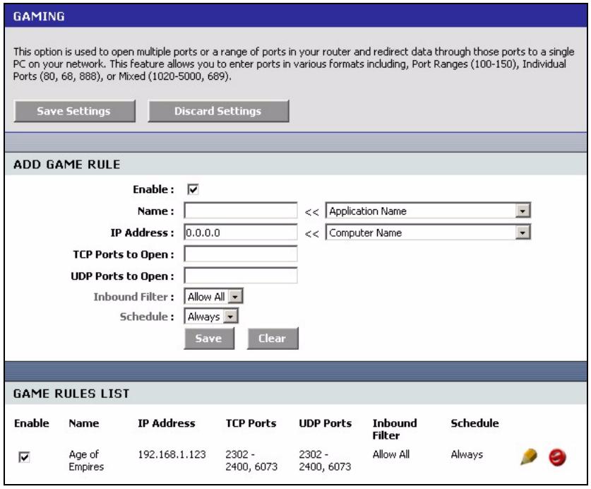
Figure 46 Advanced: Game Hosting
The following table describes the fields in this screen.
Table 26 Advanced: Game Hosting
| LABEL | DESCRIPTION |
| Enable | Click Enable to activate this feature.Clear this check box to deactivate this feature. Note that some Internet applications may not work in your network behind the ZyXEL Device. |
| Name | Enter a descriptive name for this setting.Alternatively, select a pre-defined application name from the drop-down list box.The pre-configured port number ranges for the selected application will be automatically displayed below. |
| IP Address | Enter the IP address (in dotted decimal notation) of a local computer hosting the selected service.Alternatively, select the name of a LAN computer from the drop-down list box. The IP address of the selected computer will be displayed in this field. |
| TCP Ports to Open | Specify the TCP port(s) for the application. You can enter a port number and/or a range of ports. For example, 6159-6180, 99. |
| UDP Ports to Open | Specify the UDP port(s) for the application. You can enter a port number and/or a range of ports. For example, 6159-6180, 99. |
| Inbound Filter | Select a filter action on the traffic. Select You can configure filter actions in the Inbound Filter screen. |
| Schedule | Select the name of a time setting during which this setting is active. You can configure schedules in the Schedules screen. |
| Save | Click Save to save the changes of a configuration screen for the current session. |
| Clear | Click Clear to start configuring a screen again. |
| Game Rules List | |
| Enable | Select this option to activate this setting. Clear this checkbox to disable this setting. |
| Name | This field displays the descriptive name for this setting. |
| IP Address | This field displays the IP address of the local computer to which the specified traffic is forwarded. |
| TCP Ports | This field displays the TCP port(s) the specified traffic is forwarded. |
| UDP Ports | This field displays the UDP port(s) the specified traffic is forwarded. |
| Inbound Filter | This field displays the name of the filter on the incoming traffic. |
| Schedule | This field displays the name of the schedule to use. |
7.2 Virtual Server
With the virtual server (also known as port forwarding) feature, you can make inside (behind NAT on the LAN) servers, for example, web or FTP, visible to the outside world even though NAT makes your whole inside network appear as a single computer to the outside world.
You may enter a single port number or a range of port numbers to be forwarded, and the local IP address of the desired server. The port number identifies a service; for example, web service is on port 80 and FTP on port 21. In some cases, such as for unknown services or where one server can support more than one service (for example both FTP and web service), it might be better to specify a range of port numbers. You can allocate a server IP address that corresponds to a port or a range of ports.
Many residential broadband ISP accounts do not allow you to run any server processes (such as a Web or FTP server) from your location. Your ISP may periodically check for servers and may suspend your account if it discovers any active services at your location. If you are unsure, refer to your ISP.
7.2.1 Common Services and Port Numbers
The most often used port numbers are shown in the following table. Please refer to RFC 1700 for further information about port numbers.
Table 27 Virtual Server: Common Services and Port Numbers
| SERVICES | PORT NUMBER |
| ECHO | 7 |
| FTP (File Transfer Protocol) | 21 |
| SMTP (Simple Mail Transfer Protocol) | 25 |
| DNS (Domain Name System) | 53 |
| Finger | 79 |
| HTTP (Hyper Text Transfer protocol or WWW, Web) | 80 |
| POP3 (Post Office Protocol) | 110 |
| NNTP (Network News Transport Protocol) | 119 |
| SNMP (Simple Network Management Protocol) | 161 |
| SNMP trap | 162 |
| PPTP (Point-to-Point Tunneling Protocol) | 1723 |
7.2.2 Virtual Server Setup
To configure virtual server settings, click Advanced > Virtual Server.
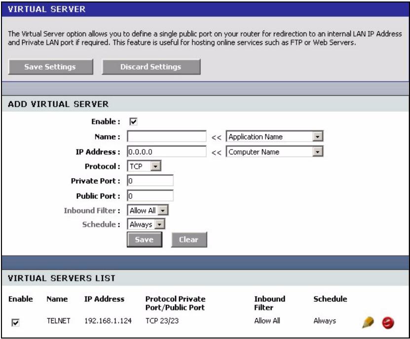
Figure 47 Advanced: Virtual Server
The following table describes the labels in this screen.
Table 28 Advanced: Virtual Server
| LABEL | DESCRIPTION |
| Active | Select this check box to enable this virtual server setting. Clear this check box to disallow forwarding of these ports to an inside server without having to delete the entry. |
| Name | Enter a name to identify this port-forwarding rule.Alternatively, select a pre-defined name from the drop-down list box to have the ZyXEL Device fill in the default port numbers for the selected service. |
| IP Address | Enter the inside IP address of the inside server.Alternatively, select the name of a LAN computer from the drop-down list box to have the ZyXEL Device fill in the IP address of the computer. |
| Protocol | Select the protocol type (TCP, UDP or Both). |
| Private Port | Enter the port number to which you want the ZyXEL Device to translate the public port. |
| Public Port | Enter the incoming port number for the selected service. |
| Inbound Filter | Select a filter action on the traffic. Select You can configure filter actions in the Inbound Filter screen. |
| Schedule | Select the name of a time setting during which this setting is active. You can configure schedules in the Schedules screen. |
| Save | Click this button to save the changes of a configuration screen for the current session. |
| Clear | Click this button to start configuring a screen again. |
| Virtual Server List | |
| Enable | Select this check box to enable this virtual server setting. Clear this check box to disallow forwarding of these ports to an inside server without having to delete the entry. |
| Name | This field displays the descriptive name for this setting. |
| IP Address | This field displays the IP address of the inside server. |
| Protocol | This field displays the protocol type. |
| Private Port | This field displays the port number to which you want the ZyXEL Device to translate the public port. |
| Public Port | This field displays the incoming port number. |
| Inbound Filter | This field displays the name of the filter on the incoming traffic. |
| Schedule | This field displays the name of the schedule to use. |
7.3 Applications
You can enable Application Layer Gateway (ALG) to allow certain NAT un-friendly applications (such as SIP) to operate properly through the ZyXEL Device. Alternatively, you can configure port triggering to allow computers on the LAN to dynamically take turns using the service
7.3.1 Port Triggering
Some services use a dedicated range of ports on the client side and a dedicated range of ports on the server side. With regular port forwarding (or virtual server setup) you set a forwarding port in NAT to forward a service (coming in from the server on the WAN) to the IP address of a computer on the client side (LAN). The problem is that port forwarding only forwards a service to a single LAN IP address. In order to use the same service on a different LAN computer, you have to manually replace the LAN computer's IP address in the forwarding port with another LAN computer's IP address.
Trigger port forwarding solves this problem by allowing computers on the LAN to dynamically take turns using the service. The ZyXEL Device records the IP address of a LAN computer that sends traffic to the WAN to request a service with a specific port number and protocol ("trigger" port and protocol). When the ZyXEL Device's WAN port receives a response with a specific port number and protocol ("input" port and protocol), the ZyXEL Device forwards the traffic to the LAN IP address of the computer that sent the request. After that computer's connection for that service closes, another computer on the LAN can use the service in the same manner. This way you do not need to configure a new IP address each time you want a different LAN computer to use the application.
7.3.2 Configuring Special Applications
Use the Special Applications screen to configure port triggers and set up ALG passthroughs for specific applications (such as online games).
Click Advanced > Applications to display the configuration screen.
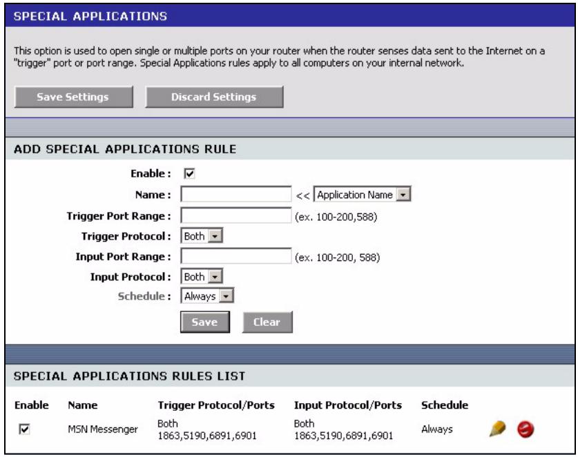
Figure 48 Advanced: Applications
The following table describes the labels in this screen.
Table 29 Advanced: Applications
| LABEL | DESCRIPTION |
| Add Special Applications Rule | |
| Enable | Select this option to activate this rule. |
| Name | Enter a descriptive name for identification purposes. Alternatively, select a pre-defined application name from the drop-down list box to have the ZyXEL Device fill in the default port numbers and protocol type for the selected application. |
| Trigger Port Range | The trigger port is a port (or a range of ports) that causes (or triggers) the ZyXEL Device to record the IP address of the LAN computer that sent the traffic to a server on the WAN. Specify a port or a range of ports. |
| Trigger Protocol | Select a protocol type for the application. |
| Input Port Range | Incoming is a port (or a range of ports) that a server on the WAN uses when it sends out a particular service. The ZyXEL Device forwards the traffic with this port (or range of ports) to the client computer on the LAN that requested the service. Specify a port or a range of ports. |
| Input Protocol | Select the protocol used by the traffic coming to the router through the opened port range. |
| Schedule | Select the name of a time setting during which this setting is active. You can configure schedules in the Schedules screen. |
| Save | Click Save to save the changes of a configuration screen for the current session. |
| Clear | Click Clear to start configuring a screen again. |
| Special Applications Rule List | |
| Enable | Select this check box to enable this trigger port setting. Clear this check box to deactivate it. |
| Name | This field displays the descriptive name of this trigger port setting. |
| Trigger Protocol/Ports | This field displays the trigger port (or port range) and the trigger protocol type. |
| Input Protocol/Ports | This field displays the input port (or port range) and the input protocol type. |
| Schedule | This field displays the name of the schedule to use. |
7.4 StreamEngine™
Use the StreamEngine screen to configure traffic priorities. This improves network quality for your applications (such as online gaming). StreamEngine improves your online gaming experience by ensuring that your game traffic is prioritized over other network traffic, such as FTP or Web.
For better performance, use the Automatic Classification option to automatically set the priority for your applications.
Click Advanced > StreamEngine to display the configuration screen.
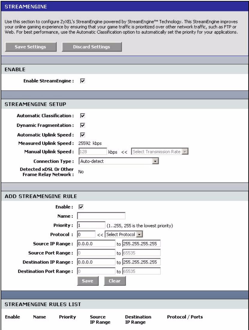
Figure 49 Advanced:StreamEgine
The following table describes the labels in this screen.
Table 30 Advanced:StreamEngine
| LABEL | DESCRIPTION |
| EnableStreamEngine | Select this option to enable this feature. |
| StreamEngine Setup | |
| AutomaticClassification | Select this option to set the ZyXEL Device to automatically classify the traffic based on the default |
| DynamicFragmentation | Select this option to set the ZyXEL Device to break up large packets with high priority. This improves transmission quality. |
| AutomaticUplink Speed | Select this option to set the ZyXEL Device to automatically detect and set the optimum WAN connection speed. |
| MeasuredUplink Speed | This field displays the detected transmission speed of the WAN connection that was last established. This uplink speed may be different from the actual transmission speed depending on your network environment and line condition. |
| Manual Uplink Speed | This field is not applicable when you select the Automatic Uplink Speed option above. Enter a number or select a pre-defined choice from the drop-down list box to manually set the uplink speed for the WAN connection. |
| Connection Type | Select Auto-detect to set the ZyXEL Device to automatically detect the Internet connection type. Select xDSL or Other Frame Relay Network if the ZyXEL Device connects to the Internet via a DSL modem. Select Cable or Other Broadband Network if the ZyXEL Device connects to the Internet via a cable modem. |
| Detected xDSL or Framerelay Network | This field is applicable when you select Auto-detect in the Connection Type field. This field displays the name of the detected line connection type. |
| Add StreamEngine Rule | |
| Enable | Select this option to enable this rule. |
| Name | Enter a descriptive name for identification purposes. |
| Priority | Specify a priority for the traffic type specified below. Enter a number between 1 (highest) and 255 (lowest). |
| Protocol | Enter the protocol number or select a pre-defined protocol type from the drop-down list box. |
| Source IP Range | Specify one or a range of source IP addresses in the fields provided. Enter the same IP address in the to field if you want to specify one IP address. |
| Source Port Range | Specify one or a range of source port numbers. Enter the same number in the to field if you want to specify one source port. |
| Destination IP Range | Specify one or a range of destination IP addresses in the fields provided. Enter the same IP address in the to field if you want to specify one IP address. |
| Destination Port Range | Specify one or a range of destination port numbers. Enter the same number in the to field if you want to specify one destination port. |
| Save | Click Save to save the settings. |
| Clear | Click Clear to start configuring this part of the screen again. |
| StreamEngine Rule List | |
| Enable | Select this option to activate this rule. Clear this check box to disable this rule without deleting it. |
| Name | THis field displays the descriptive name for the rule. |
| Priority | This field displays the priority level (1 to 255) of this rule. |
| Source IP Range | This field displays one or a range of source IP addresses. |
| Destination IP Range | This field displays one or a range of destination IP addresses. |
| Protocol/Ports | This field displays the protocol and port numbers. |
7.5 Routing
Each remote node specifies only the network to which the gateway is directly connected, and the ZyXEL Device has no knowledge of the networks beyond. For instance, the ZyXEL Device knows about network N2 in the following figure through remote node Router 1. However, the ZyXEL Device is unable to route a packet to network N3 because it doesn't know that there is a route through the same remote node Router 1 (via gateway Router 2). The static routes are for you to tell the ZyXEL Device about the networks beyond the remote nodes.
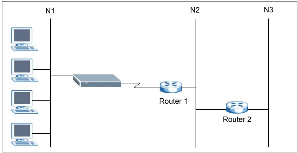
Figure 50 Example of Static Routing Topology
To view the routing table configure static routes, click Advanced > Routing to display the configuration screen.
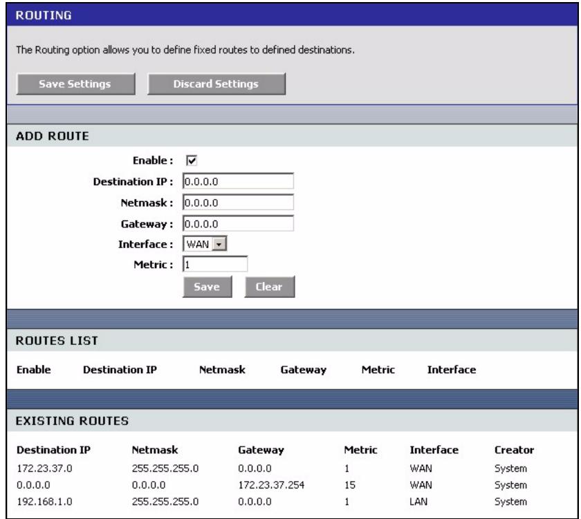
Figure 51 Advanced: Routing
The following table describes the labels in this screen.
Table 31 Advanced: Routing
| LABEL | DESCRIPTION |
| Add Route | |
| Enable | Select this option to activate this setting. This field is not applicable for pre-defined routes. |
| Destination IP | Enter the destination IP address in dotted decimal notation. |
| Netmask | Enter the subnet mask. |
| Gateway | Enter the IP address of the gateway device for the selected interface below. |
| Interface | Select an interface to which you want to apply the setting. |
| Metric | Metric represents the “cost” of transmission for routing purposes. IP routing uses hop count as the measurement of cost, with a minimum of 1 for directly connected networks. Enter a number that approximates the cost for this link. The number need not be precise, but it must be between 1 and 15. In practice, 2 or 3 is usually a good number. |
| Save | Click Save to save the settings. |
| Clear | Click Clear to start configuring this part of the screen again. |
| Routes List | |
| Enable | Select this option to activate this rule. Clear this check box to disable this rule without deleting it. |
| Destination IP | This field displays the destination IP address. |
| Netmask | This field displays the subnet mask for the destination IP address above. |
| Gateway | This field displays the IP address of the gateway device. |
| Metric | This field displays the “cost” of this route. |
| Interface | This field displays the interface to which this routing setting is applied. |
| Exiting Routes | |
| Destination IP | This field displays the destination IP address. |
| Netmask | This field displays the subnet mask for the destination IP address above. |
| Gateway | This field displays the IP address of the gateway device. |
| Metric | This field displays the “cost” of this route. |
| Interface | This field displays the interface to which this routing setting is applied. |
| Creator | This field displays the person/device that created this static route on the ZyXEL Device. |
7.6 Access Control
Internet access control allows you to create and enforce Internet access policies tailored to your needs. Access control gives you the ability to block specified computers and/or applications from accessing the Internet. You can also set a schedule for when the ZyXEL Device performs content filtering.
Follow the steps below to configure an access control rule.
1 Click Advanced > Access Control to display the configuration screen.
2 Select Enable Access Control to activate this feature.
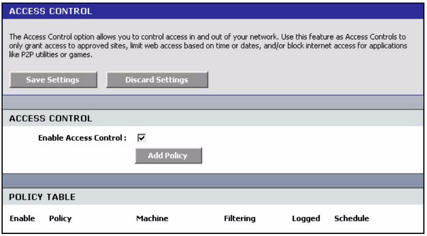
Figure 52 Advanced: Access Control
3 Click Add Policy to display the wizard screen. This screen outlines the steps to create an access control policy. Click Next.
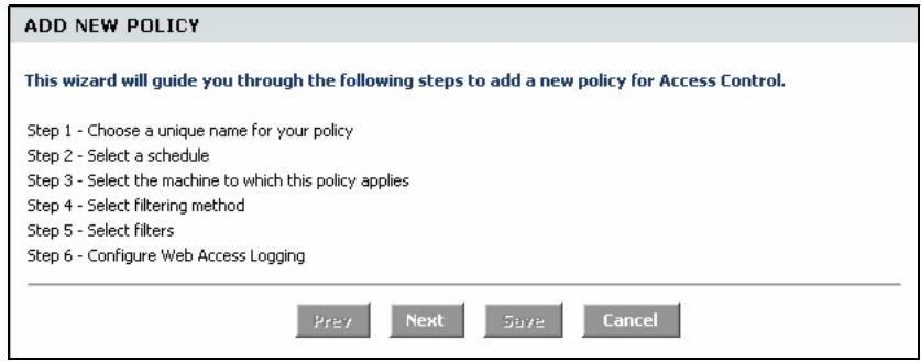
Figure 53 Advanced: Access Control: Wizard
4 In the first wizard screen, enter a descriptive name for identification purposes. Click Next to continue.
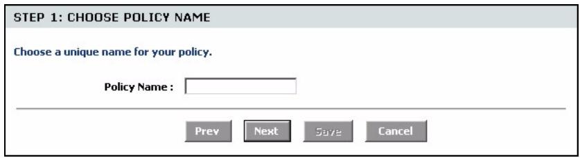
Figure 54 Advanced: Access Control: Wizard: Policy Name
5 Specify the time this rule is active.
Select the name of a schedule from the drop-down list box. You can configure a schedule in the Schedule screen.
Click Next to continue.
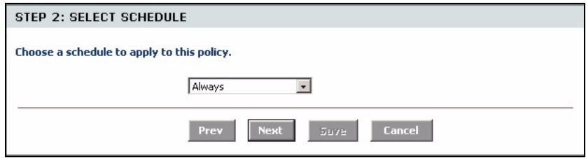
Figure 55 Advanced: Access Control: Wizard: Select Schedule
6 In this wizard screen, specify the address type and the Ethernet device(s) to which the settings apply. Click Next.
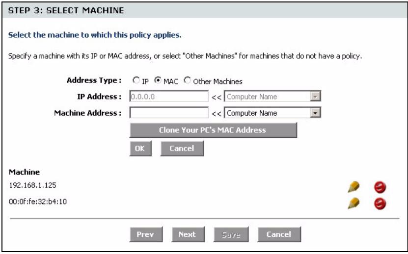
Figure 56 Advanced: Access Control: Wizard: Select Machine
The following table describes the labels in this screen.
Table 32 Advanced: Access Control: Wizard: Select Machine
| LABEL | DESCRIPTION |
| Address Type | Select the address type this rule checks. |
| IP Address | This field is applicable when you select IP in the Address Type field above. Enter the IP address of a device to which you want to apply this rule. Alternatively, select a device name from the drop-down list box. |
| MAC Address | This field is applicable when you select MAC in the Address Type field. Enter the MAC address of the device to which you want to apply this rule. Alternatively, select a device name from the drop-down list box. |
| Copy Your PC's MAC Address | This button is applicable when you select MAC in the Address Type field. Click this button to copy the MAC address of your computer. |
| OK | Click OK to add the Ethernet device settings. |
| Cancel | Click Cancel to start configuring this part of the screen again. |
| Machine | This field displays the IP address or MAC address of the Ethernet device(s) to which the access control policy is applied. |
| Schedule | Specify the time this rule is active. Select the name of a schedule from the drop-down list box. You can configure a schedule in the Schedule screen. |
| Apply Web Filter | Select this option to apply the web filters you configure in the Web Filter screen. |
| Log Internet Access | Select this option to set the ZyXEL Device to create logs for Internet access activity. |
| Filter Ports | Click this button to display the fields you use to configure port filters. |
| Port Filter Rules | |
| Enable | Select this option to activate this rule. Clear this check box to deactivate this rule. |
| Name | Enter a descriptive name for identification purposes. |
| Dest IP Start | Enter the start of the destination IP address range. |
| Dest IP End | Enter the end of the destination IP address range. |
| Protocol | Select a protocol type from the drop-down list box. |
| Dest Port Start | Enter the start of the destination port range. |
| Dest Port End | Enter the end of the destination port range. |
| Save | Click Save to save the settings in this part of the screen. |
| Clear | Click Clear to start configuring this part of the screen again. |
| Access Control Rules List | |
| Enable | Select this option to activate the rule. Clear this check box to disable the rule without deleting it. |
| Policy | This field displays the name of the port filter policy you configured for this access control rule. |
| Machine | This field displays the IP or MAC address of the device to which this access control rule is applied. |
| Schedule | This field displays the name of the schedule to use. |
| Web Filter | This field indicates whether web filters apply to this access control rule. |
| Logged | This field indicates whether Internet access activities are logged. |
7 Select the access control method, the filter(s) to apply and click Next.
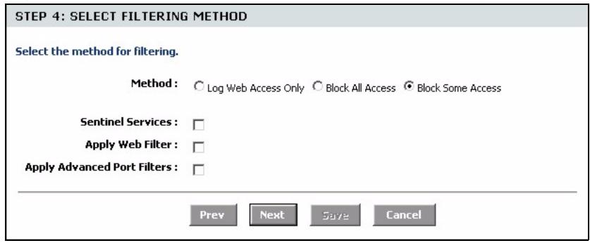
Figure 57 Advanced: Access Control: Wizard: Filtering Method
The following table describes the labels in this screen.
Table 33 Advanced: Access Control: Wizard: Filtering Method
| LABEL | DESCRIPTION |
| Method | |
| Log Web Access Only | Select this option to set the ZyXEL Device to create logs for Internet access activity. |
| Block All Access | Select this option to disallow the specified Ethernet device(s) from accessing the Internet. |
| Block Some Access | Select this option to allow or deny access to specified destination(s). |
| Sentinel Services | This field displays when you select Block Some Access. Select this option to block access to web sites classified in the specified category(ies). |
| Apply Web Filter | This field displays when you select Block Some Access. Select this option to apply the web filters you configure in the Web Filter screen. |
| Apply Advanced Port Filters | This field displays when you select Block Some Access. Select this option to apply the web filters you configure in the Port Filter screen. |
| Filter Ports | Click this button to display the fields you use to configure port filters. |
| Port Filter Rules | |
| Enable | Select this option to activate this rule. Clear this check box to deactivate this rule. |
| Name | Enter a descriptive name for identification purposes. |
| Dest IP Start | Enter the start of the destination IP address range. |
| Dest IP End | Enter the end of the destination IP address range. |
| Protocol | Select a protocol type from the drop-down list box. |
| Dest Port Start | Enter the start of the destination port range. |
| Dest Port End | Enter the end of the destination port range. |
| Save | Click Save to save the settings in this part of the screen. |
| Clear | Click Clear to start configuring this part of the screen again. |
| Access Control Rules List | |
| Enable | Select this option to activate the rule. Clear this check box to disable the rule without deleting it. |
| Policy | This field displays the name of the port filter policy you configured for this access control rule. |
| Machine | This field displays the IP or MAC address of the device to which this access control rule is applied. |
| Schedule | This field displays the name of the schedule to use. |
| Web Filter | This field indicates whether web filters apply to this access control rule. |
| Logged | This field indicates whether Internet access activities are logged. |
8 If you select Sentinel Services in the previous screen, the Service Categories screen displays. Use this screen to configure category-based content filtering.
This screen varies depending on what you select in the Categories Selection field.
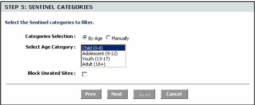
Figure 58 Advanced: Access Control: Wizard: Filtering Method
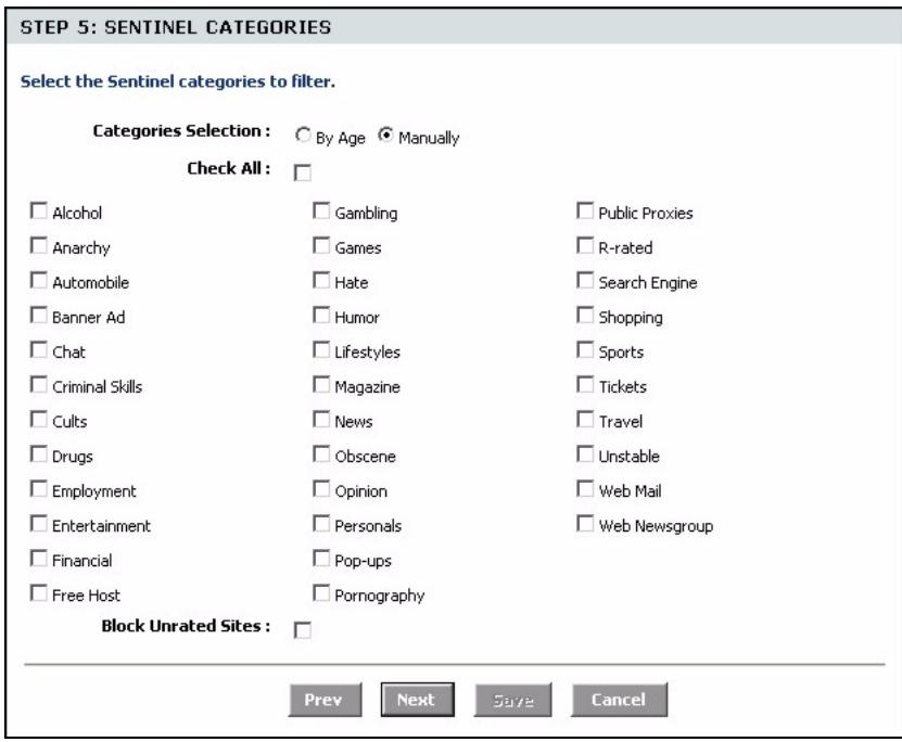
The following table describes the labels in this screen.
Table 34 Advanced: Access Control: Wizard: Filtering Method
| LABEL | DESCRIPTION |
| Category Selection | Select By Age to block access to web sites categorized by age group. Select Manually to select the web site categories manually. |
| Select Age Category | Select an age group from the list. |
| Check All | Select this option to select all categories below. |
| Block Unrated Sites | Select this option to prevent users from accessing web pages that are not categorized. |
9 If you select Apply Advanced Port Filters in the previous screen, the Port Filter screen displays. Use this screen to configure port filter(s) that blocks access to specified port(s) on a computer.
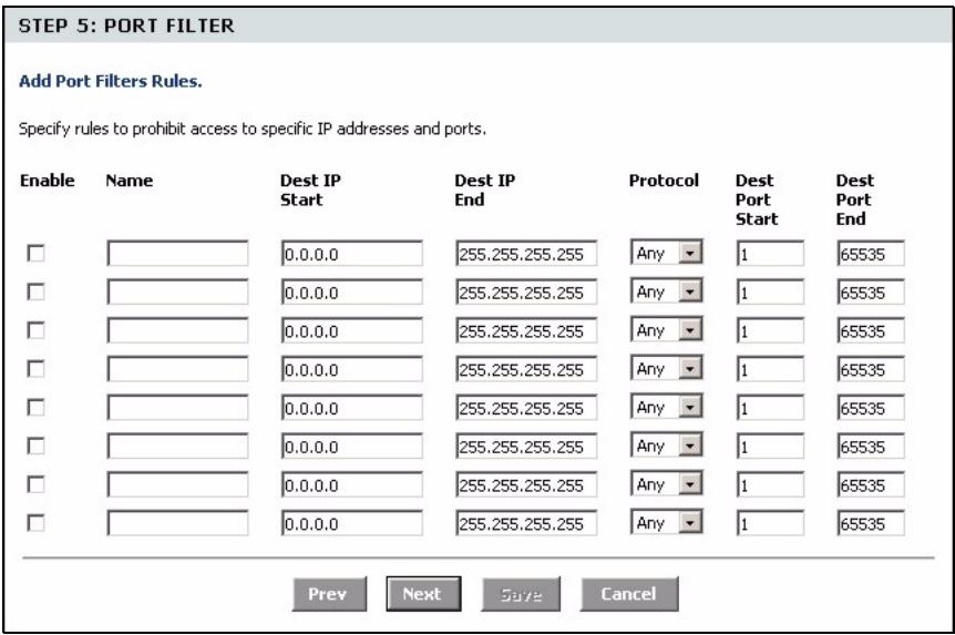
Figure 59 Advanced: Access Control: Wizard: Port Filter
The following table describes the labels in this screen.
Table 35 Advanced: Access Control: Wizard: Filtering Method
| LABEL | DESCRIPTION |
| Enable | Select this option to activate this rule. Clear this check box to deactivate this rule. |
| Name | Enter a descriptive name for identification purposes. |
| Dest IP Start | Enter the start of the destination IP address range. |
| Dest IP End | Enter the end of the destination IP address range. |
| Protocol | Select a protocol type from the drop-down list box. |
| Dest Port Start | Enter the start of the destination port range. |
| Dest Port End | Enter the end of the destination port range. |
10 In this screen, select Enabled to set the ZyXEL Device to create logs for Internet access activity. Select Disabled to deactivate this feature.
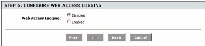
Figure 60 Advanced: Access Control: Wizard: Web Access Logging
11Click Save to save the settings and return to the main Access Control screen. You should see the new access control policy in the Policy Table.
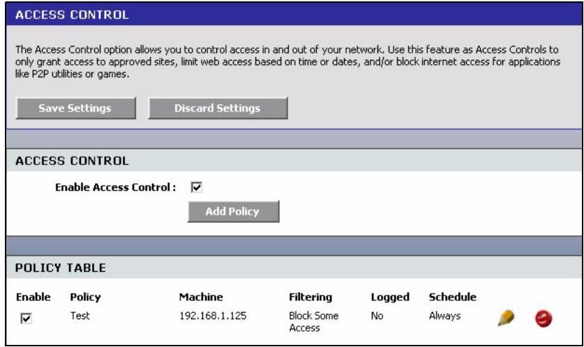
Figure 61 Advanced: Access Control: Example
7.7 Web Filter
The Web Filter screen gives you the ability to allow access only to web sites that you specify.
Click Advanced > Web Filter to display the configuration screen.
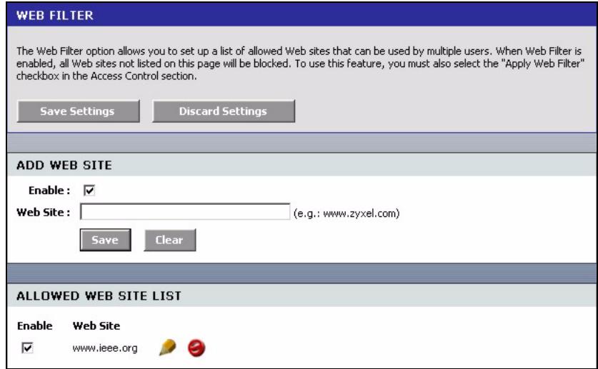
Figure 62 Advanced: Web Filter
The following table describes the labels in this screen.
Table 36 Advanced: Web Filter
| LABEL | DESCRIPTION |
| Add Web Site | |
| Enable | Select this option to activate this setting. Clear this check box to disable it. |
| Web Site | Enter the web site address to which you want to allow access. For example, if you enter zyxel.com, the Zyxel Device allows access to www.zyxel.com, support.zyxel.com or product.zyxel.com, etc. For web sites that obtain data from another web site, you need to allow access to those web sites as well. For example, if www.zyxel.com gets a graphic file from www.mysite.com, then you must also enter www.mysite.com in this screen. Note: Do NOT enter “http://”. |
| Save | Click Save to save the settings in this part of the screen. |
| Clear | Click Clear to start configuring this part of the screen again. |
| Allowed Web Site List | This table lists the addresses of the web sites that you want to allow access. |
| Enable | Select this option to allow access to this web site. Clear this check box to block access. |
| Web Site | This field displays the web site address. |
7.8 MAC Filter
MAC address filtering means sifting traffic going through the ZyXEL Device based on the source and/or destination MAC addresses. You can set the ZyXEL Device to filter packets from connected wireless clients or computers on the wired LAN.
Click Advanced > MAC Filter to display the configuration screen.
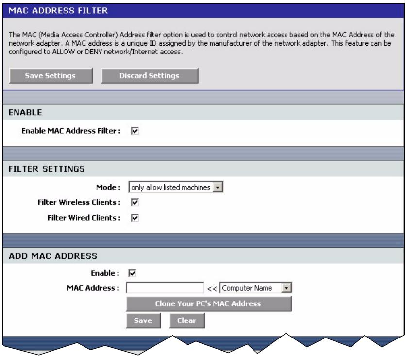
Figure 63 Advanced: MAC Filter
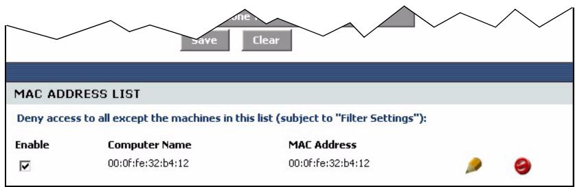
The following table describes the labels in this screen.
Table 37 Advanced: MAC Filter
| LABEL | DESCRIPTION |
| Enable | Select Enable MAC Address Filter to activate this setting. Clear this check box to disable it. |
| Filter Settings | |
| Mode | Select only deny listed machines to block frames to/from the specified MAC address(es).Select only allow listed machines to forward frames to/from the specified MAC address(es). |
| Filter Wireless Clients | Select this option to apply the filter settings to the wireless clients. |
| Filter Wired Clients | Select this option to apply the filter settings to the wired computers on the LAN. |
| Add MAC Address | |
| Enable | Select Enable to activate this filter setting. Clear this check box to disable it. |
| MAC Address | Enter the MAC address (in six pairs of dotted hexadecimal notation) of a computer whose traffic you want to filter. Or select a computer MAC address from the drop-down list box. |
| Copy Your PC's MAC Address | Click this button to copy the MAC address of your computer.Note: In order for the ZyXEL Device to copy your computer's MAC address, your computer must be connected directly to the ZyXEL Device. |
| Save | Click Save to save the settings in this part of the screen. |
| Clear | Click Clear to start configuring this part of the screen again. |
| MAC Address List | |
| Enable | Select this option to activate this filter setting. Clear this check box to disable it without deleting it. |
| Computer Name | This field displays the name of the computer. |
| MAC Address | This field displays the MAC address of a computer whose traffic you want to filter. |
7.9 Firewall
Stateful packet inspection (SPI) firewalls restrict access by screening data packets against defined access rules. They make access control decisions based on IP address and protocol. They also "inspect" the session data to assure the integrity of the connection and to adapt to dynamic protocols. These firewalls generally provide the best speed and transparency; however, they may lack the granular application level access control or caching that some proxies support.
The ZyXEL Device firewall is a stateful inspection firewall and is designed to protect against Denial of Service attacks when activated. The ZyXEL Device's purpose is to allow a private Local Area Network (LAN) to be securely connected to the Internet. The ZyXEL Device can be used to prevent theft, destruction and modification of data, as well as log events, which may be important to the security of your network. The ZyXEL Device also has packet-filtering capabilities.
7.9.1 DMZ
The DeMilitarized Zone (DMZ) provides a way for public servers (Web, e-mail, FTP, etc.) to be visible to the outside world (while still being protected from DoS (Denial of Service) attacks such as SYN flooding and Ping of Death). These public servers can also still be accessed from the secure LAN.
7.9.2 ALG
Some applications cannot operate through NAT (are NAT un-friendly) because they embed IP addresses and port numbers in their packets' data payload. The ZyXEL Device examines and uses IP address and port number information embedded in the data stream. When a device behind the ZyXEL Device uses an application for which the ZyXEL Device has ALG service enabled, the ZyXEL Device translates the device's private IP address inside the data stream to a public IP address. It also records session port numbers and dynamically creates implicit NAT port forwarding and firewall rules for the application's traffic to come in from the WAN to the LAN.
7.9.3 NAT Endpoint Filtering
NAT Endpoint Filtering controls how the ZyXEL Device's NAT manages incoming connection requests to ports that are already being used. Three filtering options are available on UDP and TCP packets.
- Endpoint Independent
Once a LAN-side application has created a connection through a specific port, NAT will forward any incoming connection requests with the same port to the LAN-side application regardless of their origin. This is the least restrictive option, giving the best connectivity and allowing some applications (for example, P2P applications) to behave almost as if they are directly connected to the Internet.
The Endpoint Independent filters take priority over inbound filters or schedules, so it is possible for an incoming session request related to an outgoing session to enter through a port in spite of an active inbound filter on that port. However, packets will be rejected as expected when sent to blocked ports (whether blocked by the schedule or by inbound filter) for which there are no active sessions.
- Address Restricted
With the Address Restricted option, NAT forwards incoming connection requests to a LAN-side host only when they come from the same IP address with which a connection was established. This allows the remote application to send data back through a port different from the one used when the outgoing session was created.
Use Address Restricted Filters to allow your ZyXEL Device to communicate with routers using other NAT types (such as symmetric NATs) and still apply inbound filters and scheduled access to traffic.
- Port And Address Restricted
Port and Address Restricted Filtering does not forward any incoming connection requests with the same port address as an already establish connection. This ensures that inbound filters and schedules work. In some cases, you may need to configure port triggers, virtual servers, or port forwarding to open the ports used by the applications.
7.9.4 Configuring Firewall
To configure the firewall and DMZ settings, click Advanced > Firewall to display the configuration screen.
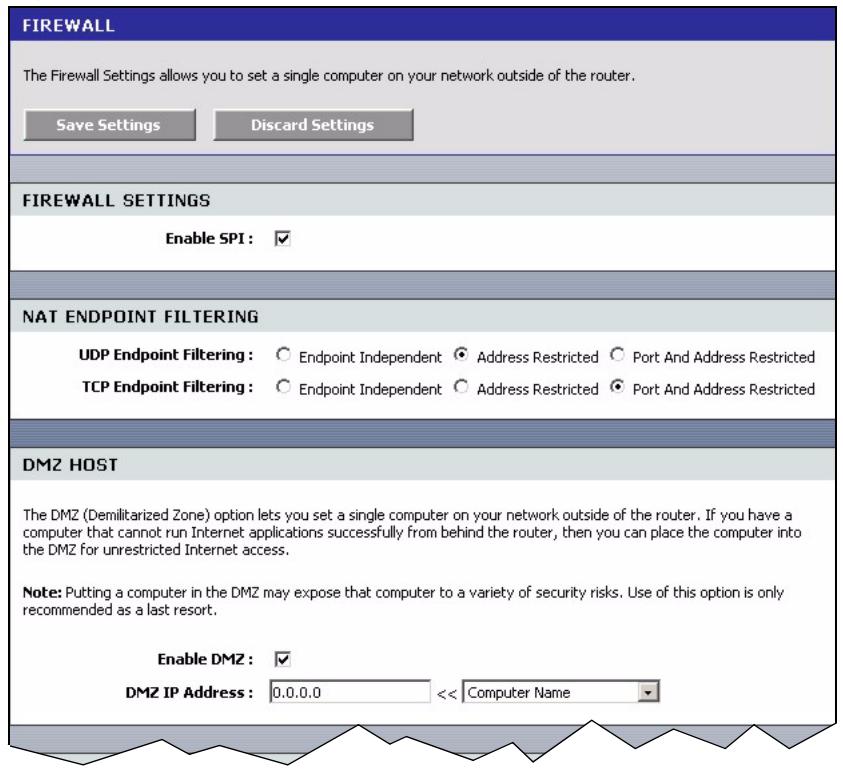
Figure 64 Advanced: Firewall
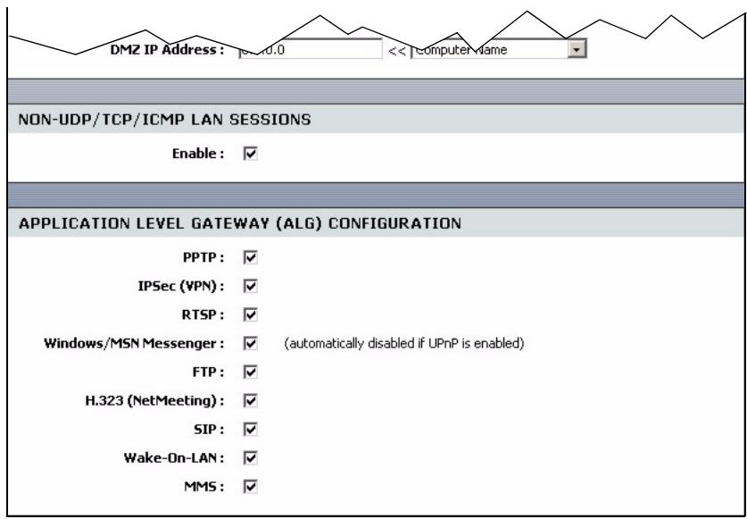
The following table describes the labels in this screen.
Table 38 Advanced: Firewall
| LABEL | DESCRIPTION |
| Enable SPI | Select this option to activate stateful packet inspection. Clear this check box to disable this feature. |
| NAT Endpoint Filtering | The NAT Endpoint Filtering options control how the router's NAT manages incoming connection requests to ports that are already being used. |
| UDP Endpoint Filtering | Select the end-point filtering option for UDP traffic. |
| TCP Endpoint Filtering | Select the end-point filtering option for TCP traffic. |
| DMZ Host | |
| Enable DMZ | Select this option to activate the DMZ feature to protect the specified device on the LAN. |
| DMZ IP Address | Enter the IP address (in dotted decimal notation) of a computer which you want to protect on the LAN. Or select a computer IP address from the drop-down list box. |
| Non-UDP/TCP/ICMP LAN Sessions | You can set your ZyXEL Device to recognize sessions initiated by a VPN connection from the LAN to the Internet (WAN) even though the VPN connection uses an unknown protocol type (any protocols other than UDP, TCP, and ICMP). This feature allows a single VPN connection to a remote host without the need for an ALG. This feature does not apply to DMZ hosts (if enabled). DMZ hosts can handle these sessions. Select Enable to allow a single VPN connection to a remote host. For multiple VPN connections, the appropriate VPN ALG must be enabled. Clear the checkbox to disable this feature. However, you must also disable the appropriate VPN ALG to deactivate the VPN connection. |
| Application Level Gateway (ALG) Application | |
| PPTP | Select this option to allow multiple computers on the LAN to connect to a remote network using the PPTP protocol. |
| IPSec VPN | Select this option to allow multiple VPN clients to connect to a remote network using the IPSec protocol. This ALG may affect VPN connections for VPN clients using NAT traversal. In this case, clear this check box to disable this ALG. |
| RTSP | Select this option to allow applications (such as QuickTime and Real Player) that use Real Time Streaming Protocol (RTSP) to receive streaming media from the Internet. |
| Windows Messenger | Select this feature to allow the use of Microsoft Windows Messenger on computers in the LAN.Note: You must also enable the SIP ALG. |
| FTP | Select this option to allow FTP data transfer through a NAT-enabled network. You must also set up the FTP server settings in the Virtual Server screen. |
| H.232 (NetMeeting) | Select this option to allow Microsoft NetMeeting clients to communicate through a NAT-enabled network. You must also set up the NetMeeting server settings in the Virtual Server screen. |
| SIP | Select this option to allow devices and applications using VoIP (Voice over IP) to communicate over NAT.Clear this check box to disable this ALG if the devices/applications use NAT traversal. |
| Wake-On-LAN | Select this option to forward "magic packets" or wake-up packets from the WAN to a LAN computer or device with Wake-on-LAN (WOL) feature. You must also define the WOL server settings in the Virtual Server screen. The LAN IP address for the virtual server is typically set to the broadcast address of 192.168.0.255. The computer on the LAN whose MAC address is contained in the magic packet will be awakened. |
| MMS | Select this option to allow Windows Media Player, using MMS protocol, to receive streaming data from the Internet. |
7.10 Inbound Filter
An inbound filter allows you to filter packets based on IP addresses. You can use inbound filters to control access to network resources (such as a web server) or for remote management of the device.
Click Advanced > Inbound Filter to display the configuration screen.
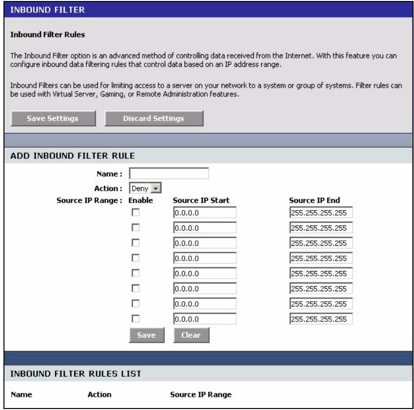
Figure 65 Advanced: Inbound Filter
The following table describes the labels in this screen.
Table 39 Advanced: Inbound Filter
| LABEL | DESCRIPTION |
| Add Inbound Filter Rule | |
| Name | Enter a descriptive name (up to 16 characters) for this filter setting. This is for identification purposes only. |
| Action | Select Deny to block packets from the specified IP address(es).Select Allow to forward packets from the specified IP address(es). |
| Source IP Range | |
| Enable | Select this option to activate the filter action on the specified IP address range.Clear this check box to disable the filter action on the IP address range. |
| Source IP Start | Enter the start of the source IP address range. |
| Source IP End | Enter the end of the source IP address range. |
| Save | Click Save to save the settings in this part of the screen. |
| Clear | Click Clear to start configuring this part of the screen again. |
| Inbound Filter Rules List | |
| Name | This field displays the name of the inbound filter. |
| Action | This field displays the action on the packets from the specified IP address range. |
| Source IP Range | This field displays the source IP address range(s). |
7.11 Advanced Wireless
Refer to Appendix B on page 128 for background information.
To configure advanced wireless settings, click Advanced > Wireless to display the screen.
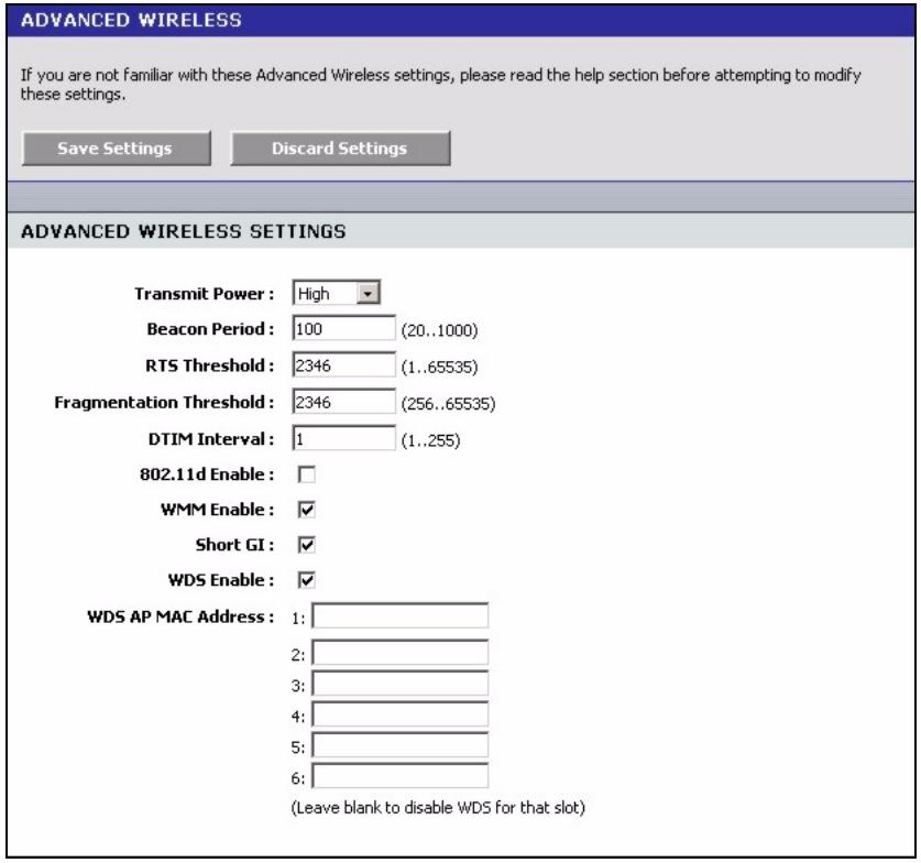
Figure 66 Advanced: Wireless
The following table describes the labels in this screen.
Table 40 Advanced: Wireless
| LABEL | DESCRIPTION |
| Advanced Wireless Settings | |
| Transmission Power | Select an option in this field to set the transmission power of the antennas to reduce your wireless coverage area. |
| Beacon Period | A wireless AP sets out a beacon to announce its presence and maintain an orderly communication between other wireless devices. Enter the time (between 20 and 1000 ms) the ZyXEL Device waits before sending a beacon to the wireless clients. |
| RTS Threshold | The RTS (Request To Send) threshold (number of bytes) is for enabling RTS/CTS. Data with its frame size larger than this value will perform the RTS/CTS handshake. Setting this value to be larger than the maximum MSDU (MAC service data unit) size turns off RTS/CTS. Setting this value to zero turns on RTS/CTS. Enter a new value between 0 and 2432. |
| Fragmentation Threshold | This is the threshold (number of bytes) for the fragmentation boundary for directed messages. It is the maximum data fragment size that can be sent. Enter a value between 256 and 2432. |
| DTIM Interval | A DTIM (Delivery Traffic Indication Message) is included in a beacon to synchronize wireless transmission. DTIM is a countdown information for wireless clients to listen to the next broadcast or multicast messages. Enter the time (between 1 and 255 ms) the ZyXEL Device waits between sending a beacon with DTIM. |
| 802.11d Enable | 802.11d is a wireless communication specification for countries where other IEEE802.11 devices are not allowed. 802.11d is suitable if you want global roaming (that is using your wireless devices worldwide). Select this option to enable this feature. |
| WMM Enable | Select this option to activate the WM (WiFi Multi-Media) feature on the ZyXEL Device. This helps reduce latency and jitter when transmitting multi-media content over the wireless connection. |
| Short GI | Select this option to set the ZyXEL Device to use a short guard interval (GI) of 400ns. This increases throughput at the cost of increased error rate in certain network environments with greater radio interference. |
| WDS Enable | Select this option to activate the WDS (Wireless Distribution System) feature. A Distribution System (DS) is a wired connection between two or more APs, while a WDS is a wireless connection. An AP using WDS can function as a wireless network bridge allowing you to wirelessly connect two wired network segments. Note: You cannot enable WPA and WDS at the same time. |
| WDS AP MAC Address | These fields display when you select WDS Enable. Enter the MAC address (in six paris of dotted hexadecimal notation) of the neighboring AP(s) that participates in the WDS. |
7.12 Schedules
You can define schedule settings on the ZyXEL Device and apply these schedule settings in other configuration screens (such as Game Hosting and Virtual Server).
Click Advanced > Schedules to display the configuration screen.
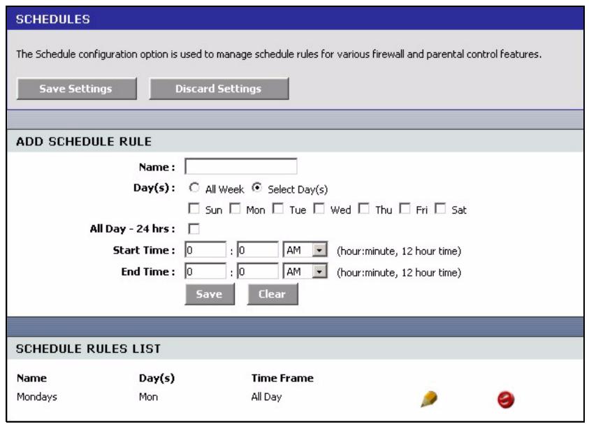
Figure 67 Advanced: Schedule
The following table describes the labels in this screen.
Table 41 Advanced: Schedule
| LABEL | DESCRIPTION |
| Name | Enter a descriptive name (up to 16 characters) for this schedule setting. This is for identification purposes only. |
| Day(s) | Select All Week or Select Day(s) to specify the day(s) of the week. |
| All Day - 24 hrs | Select this option to enable the schedule for the entire day for the specified day(s). |
| Start Time | Set the start of the schedule. |
| End Time | Set the end of the schedule. |
| Save | Click Save to save the settings in this part of the screen. |
| Clear | Click Clear to start configuring this part of the screen again. |
| Schedule Rules List | |
| Name | This field displays the descriptive for the schedule. |
| Day(s) | This field displays the day of the week the schedule is active. |
| Time Frame | This field displays the time of the day the schedule is active. |
CHAPTER 8 Tools
This chapter describes the Tools screens you use to configure login passwords, system time, logs, DDNS and firmware and configuration settings.
8.1 Administrator Settings
You can change the login account passwords, enable UPnP and configure remote access settings in the Admin screen.
8.1.1 Login Accounts
You can log into the web configurator using one of the following accounts.
- Administrator (admin)
This is the system administrator's account with full access rights. You can view system status and set the configuration screens using this account.
- Normal User (user)
This account allows you to view device system status and configuration settings in the web configurator. configuration is not allowed.
8.1.2 UPnP
Universal Plug and Play (UPnP) is a distributed, open networking standard that uses TCP/IP for simple peer-to-peer network connectivity between devices. A UPnP device can dynamically join a network, obtain an IP address, convey its capabilities and learn about other devices on the network. In turn, a device can leave a network smoothly and automatically when it is no longer in use.
8.1.3 The Admin Screen
Use the Admin screen to configure login passwords, remote management and UPnP. You can also restore and backup the device configuration in this screen.
Click Tools > Admin to display the configuration screen.
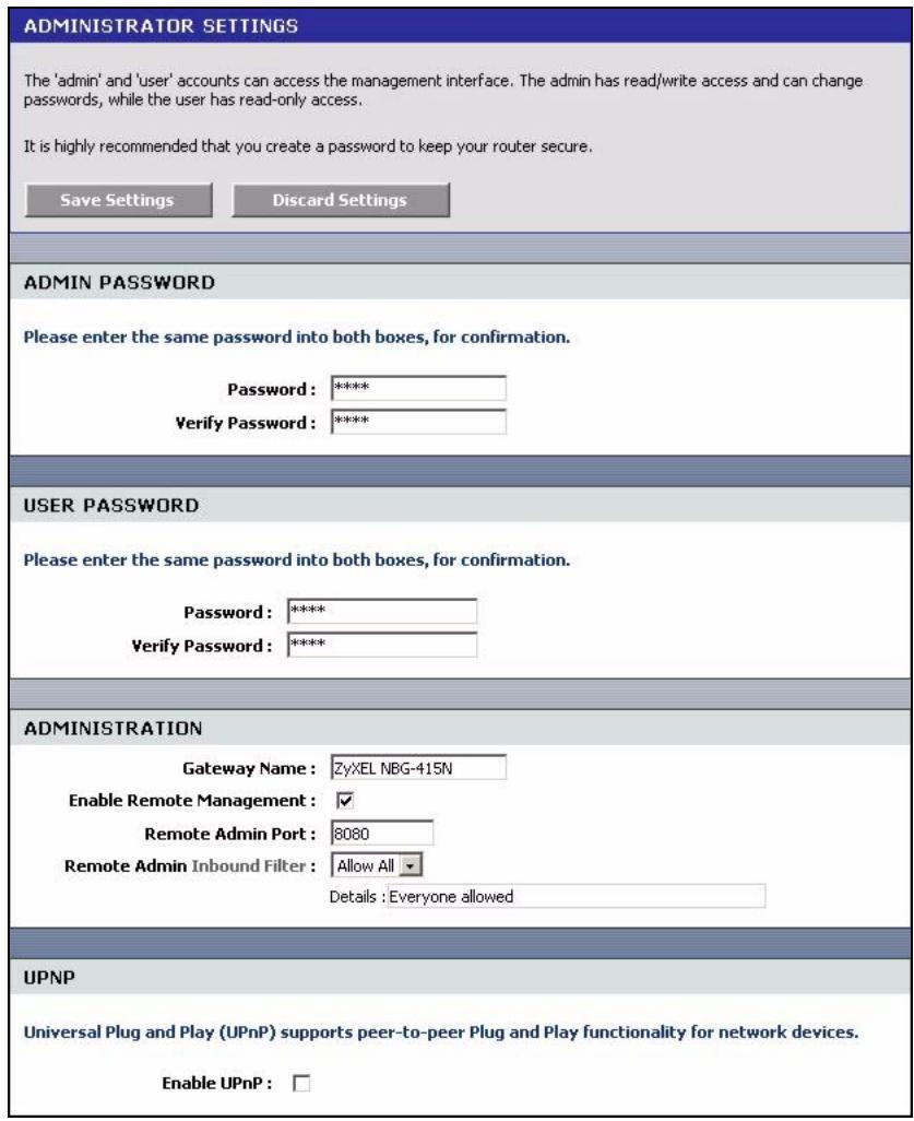
Figure 68 Tools: Admin
The following table describes the labels in this screen.
Table 42 Tools: Admin
| LABEL | DESCRIPTION |
| Admin Password | |
| Password | Type the new password in this field. You can enter up to 15 characters and spaces are not allowed. |
| Verify Password | Type the new password again in this field. |
| User Password | |
| Password | Type the new password in this field. You can enter up to 15 characters and spaces are not allowed. |
| Verify Password | Type the new password again in this field. |
| Administration | |
| Gateway Name | Enter a descriptive name (up to 32 characters) for your ZyXEL Device. This is for identification purposes only. |
| Enable Remote Management | Remote management allows you to allow access to the ZyXEL Device web configurator from the WAN. Select this option to activate this feature and set the fields that display below. Clear this check box to disable this feature. |
| Remote Admin Port | Enter the port number to access the ZyXEL Device for device management over the WAN. For example, if you enter 8080 in this field and the WAN IP address of the ZyXEL Device is 172.23.37.205, then you must enter http://172.23.37.205:8080 to access the web configurator on the ZyXEL Device. |
| Remote Admin Inbound Filter | Select an inbound filter from the drop-down list box to restrict remote management access to your ZyXEL Device over the WAN. You can select the default filters to allow or deny all access. You can configure a customer inbound filter in the Inbound Filter screen (click Advanced > Inbound Filter). Refer to Section 7.10 on page 96 for more information. |
| UPNP | |
| Enable UPNP | Select this option to activate this feature. |
| Web Configurator Language | The web configurator on the ZyXEL Device is multilingual. |
| Enable Auto Detection | Select this option to set the web configurator to automatically detect and display the interface in your language. |
8.2 System Time and Date
To change your ZyXEL Device's time and date, click Tools > Time. Use this screen to configure the ZyXEL Device's system time based on your local time zone.
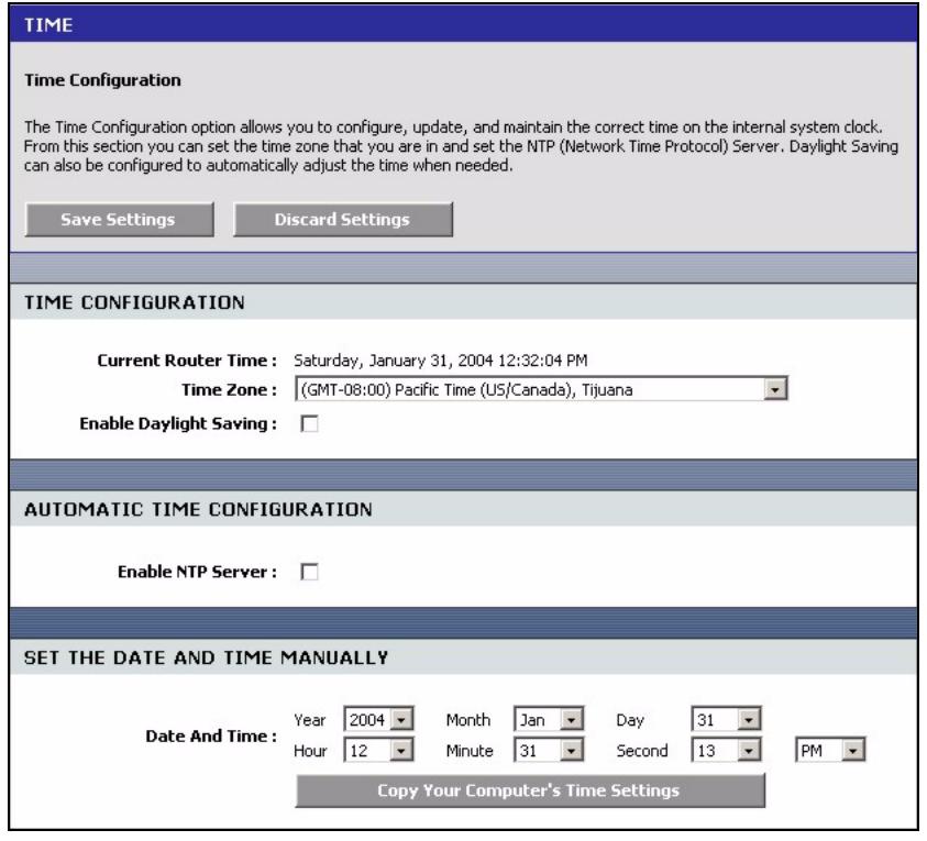
Figure 69 Tools: Time
The following table describes the labels in this screen.
Table 43 Tools: Time
| LABEL | DESCRIPTION |
| Time Configuration | |
| Current Router Time | This field displays the current system time and date. |
| Time Zone | Choose the time zone of your location. This will set the time difference between your time zone and Greenwich Mean Time (GMT). |
| Enable Daylight Saving | Daylight saving is a period from late spring to early fall when many countries set their clocks ahead of normal local time by one hour to give more daytime light in the evening. Select this option to if you use Daylight Saving Time. |
| Daylight Saving Offset | Enter the off set time for daylight saving time. |
| Daylight Saving Dates | |
| DST Start | Configure the day and time when Daylight Saving Time starts if you selected Enable Daylight Saving. The Time field uses the 24 hour format. Here are a couple of examples:Daylight Saving Time starts in most parts of the United States on the first Sunday of April. Each time zone in the United States starts using Daylight Saving Time at 2 A.M. local time. So in the United States you would select 1st, Sun, Apr and select 2 am in the Time field.Daylight Saving Time starts in the European Union on the last Sunday of March. All of the time zones in the European Union start using Daylight Saving Time at the same moment (1 A.M. GMT or UTC). So in the European Union you would select the last Sun, Mar. The time you select in the Time field depends on your time zone. In Germany for instance, you would type 2 because Germany's time zone is one hour ahead of GMT or UTC (GMT+1). |
| DST End | Configure the day and time when Daylight Saving Time ends if you selected Enable Daylight Saving. The Time field uses the 24 hour format. Here are a couple of examples:Daylight Saving Time ends in the United States on the last Sunday of October. Each time zone in the United States stops using Daylight Saving Time at 2 A.M. local time. So in the United States you would select the last Sun, Oct and select 2 am in the Time field.Daylight Saving Time ends in the European Union on the last Sunday of October. All of the time zones in the European Union stop using Daylight Saving Time at the same moment (1 A.M. GMT or UTC). So in the European Union you would select the last Sun, Oct. The time you select in the Time field depends on your time zone. In Germany for instance, you would type 2 because Germany's time zone is one hour ahead of GMT or UTC (GMT+1). |
| Automatic Time Configuration | |
| Enable NTP Server | Select this option to have the ZyXEL Device get the time and date from the Network Time Protocol (NTP) time server you specified below. |
| NTP Server Used | Enter the IP address (in dotted decimal notation) of the time server or select one from the pre-defined list. |
| Set the Date and Time Manually | These fields display when you clear the Enable NTP Server checkbox. |
| Date and Time | Set these fields to configure the system date and time. |
| Copy Your Computer's Time Settings | Click this button to get the system date and time from your computer. |
8.3 E-mail
Click Tools > E-mail configure where the ZyXEL Device is to send logs and alerts.
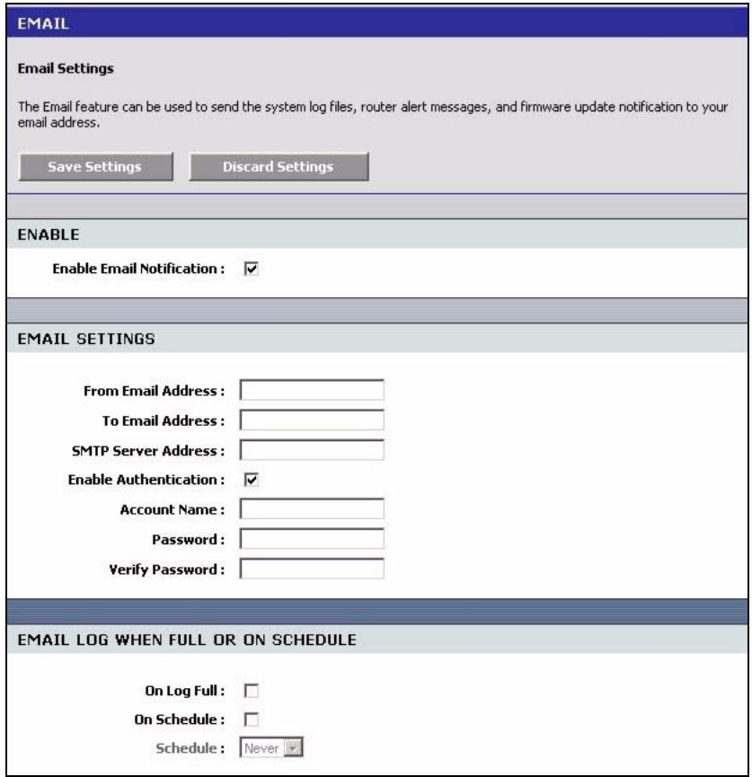
Figure 70 Tools: E-mail
The following table describes the labels in this screen.
Table 44 Tools: E-mail
| LABEL | DESCRIPTION |
| Enable | Select Enable Email Notification to activate this feature. |
| Email Settings | |
| From Email Address | Enter an e-mail as the sender. |
| To Email Address | Enter the e-mail address to which notifications are sent. |
| SMTP Server Address | SMTP (Simple Mail Transfer Protocol) is the message-exchange standard for the Internet. SMTP enables you to move messages from one e-mail server to another. Enter the IP address (in dotted decimal notation) of the mail server. |
| Enable Authentication | Select the check box to activate SMTP authentication. If mail server authentication is needed but this feature is disabled, you will not receive the e-mail logs. |
| Account Name | Enter the user name (up to 31 characters) (usually the user name of a mail account). |
| Password | Enter the password associated with the user name above. |
| Verify Password | Enter the password again for verification. |
| Email Log When Full or On Schedule | |
| On Log Full | Select this option to send logs when all log entries are filled. |
| On Schedule | Select this option to send logs at the time defined in the time selected in the Schedule field. |
8.4 System
Use the System screen to reboot or reset your ZyXEL Device. Click Tools > System to display the screen as shown.
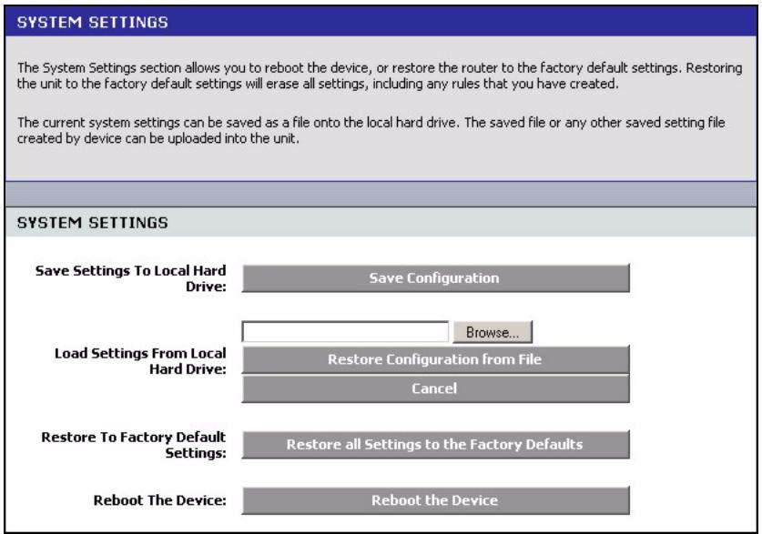
Figure 71 Tools: System
8.4.1 Save Configuration
Note: Do not turn off the ZyXEL Device while the file transfer process is taking place.
Follow the steps below to back up the current configuration of the ZyXEL Device.
1 In the web configurator, click Tools > System (see Figure 68 on page 103) and click Save Configuration.
2 A File Download screen displays. Click Save.
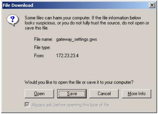
Figure 72 Tools: Admin: File Download
3 A Save As screen displays. Accept the default file location and name or specify a location and name. Click Save to back up the configuration file.

Figure 73 Tools: Admin: Save As
4 After the back up process is complete, a Download complete screen displays. Click Close to close the screen.
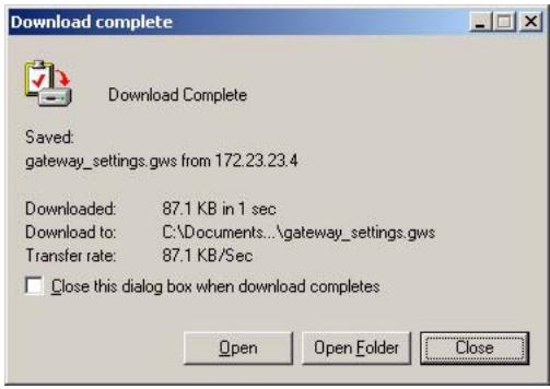
Figure 74 Tools: Admin:
8.4.2 Load Configuration
Note: Do not turn off the ZyXEL Device while the file transfer process is taking place.
Follow the steps below to restore a previously saved configuration file to the ZyXEL Device.
1 In the web configurator click Tools > System (see Figure 68 on page 103).
2 In the Load Settings From Local Hard Drive field, enter a configuration file name in the field provided or click Browse to locate it.
3 Click Restore Configuration from File to start the file upload process. A status screen displays showing the restoration progress.
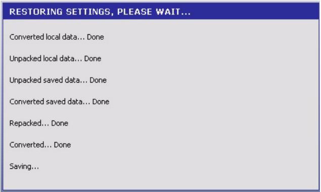
Figure 75 Tools: Admin: Configuration Restore Progress
4 After the settings are restored successfully, a screen displays as shown. Click Reboot the Device to restart the ZyXEL Device and make the changes take effect.
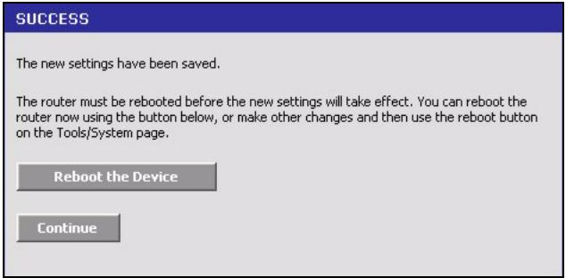
Figure 76 Tools: Admin: Configuration Restore Progress: Success
5 Click OK to restart.
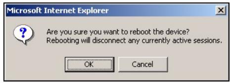
Figure 77 Tools: Admin: Configuration Restore Progress: Prompt
6 Click OK again to display the login screen.
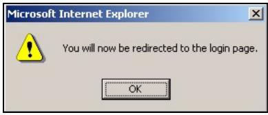
Figure 78 Tools: Admin: Configuration Restore Progress: Redirect
8.4.3 Reset Configuration
Note: When you reset the device, all custom changes will be lost.
Follow the steps below to reset your ZyXEL Device.
1 In the web configurator, click Tools > System and click Restore all Settings to the Factory Defaults.
2 A screen displays. Click OK to continue.
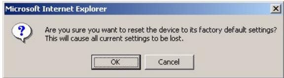
Figure 79 Tools: System: Reset
3 Wait until the ZyXEL Device finishes rebooting before accessing the web configurator.
8.4.4 Rebooting Your ZyXEL Device
Note: When you reboot the device, all unsaved changes will be lost.
Follow the steps below to restart your ZyXEL Device.
1 In the web configurator, click Tools > System and click Reboot the Device.
2 A screen displays. Click OK to continue.
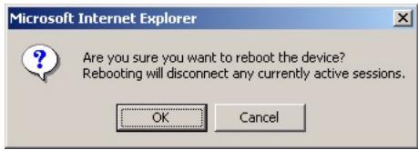
Figure 80 Tools: System:Reboot the Device
3 Wait until the ZyXEL Device finishes rebooting before accessing the web configurator.
8.5 Firmware
Use the Firmware screen to update the firmware on your ZyXEL Device.
1 Back up the current device configuration in the System screen.
1 Download the latest firmware file from www.zyxel.com.
2 In the web configurator, click Tools > Firmware.
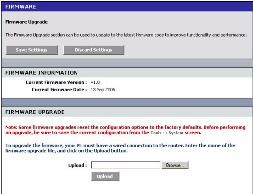
Figure 81 Tools: Firmware
3 In the Upload field, enter the new firmware file name or click Browse to locate it.
4 Click Upload to start the file transfer process.
5 A screen displays as shown, click OK to continue.
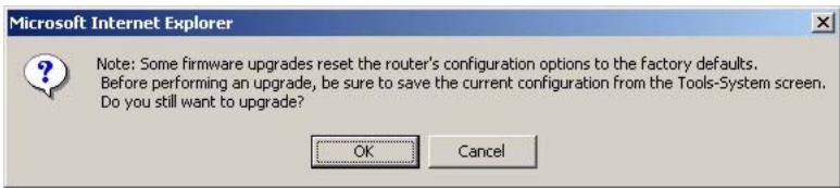
Figure 82 Tools: Firmware: Prompt
6 Click OK again to confirm the firmware file you want to upload to the device.
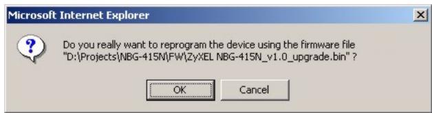
Figure 83 Tools: Firmware: Confirm
Note: Do not turn off the ZyXEL Device while the file transfer process is taking place.
7 Wait for the ZyXEL Device finishes rebooting before accessing the web configurator again. Check the firmware version and date in the Firmware screen.
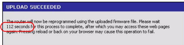
Figure 84 Tools: Firmware: Wait
8.6 DDNS
Dynamic DNS (DDNS) allows you to update your current dynamic IP address with one or many dynamic DNS services so that anyone can contact you (in NetMeeting, CU-SeeMe, etc.). You can also access your FTP server or Web site on your own computer using a domain name (for instance myhost.dhs.org, where myhost is a name of your choice) that will never change instead of using an IP address that changes each time you reconnect. Your friends or relatives will always be able to call you even if they don't know your IP address.
First of all, you need to have registered a dynamic DNS account with from a DDNS service provider (for example, www.dyndns.org). This is for people with a dynamic IP from their ISP or DHCP server that would still like to have a domain name. The Dynamic DNS service provider will give you a password or key.
Note: You must go to the Dynamic DNS service provider's website and register a user account and a domain name before you can use the Dynamic DNS service with your ZyXEL Device.
Click Tools > DDNS to display the configuration screen.
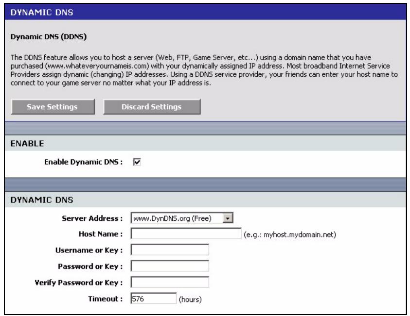
Figure 85 Tools: DDNS
The following table describes the labels in this screen.
Table 45 Tools: DDNS
| LABEL | DESCRIPTION |
| Enable | Select Enable Dynamic DNS to active this feature. |
| Dynamic DNS | |
| Service Address | Select the web address of your Dynamic DNS service provider. |
| Host Name | Enter the system name. |
| Username or Key | Enter your user name. You can use up to 31 alphanumeric characters (and the underscore). Spaces are not allowed. |
| Password or Key | Enter the password associated with the user name above. You can use up to 31 alphanumeric characters (and the underscore). Spaces are not allowed. |
| Verify Password or Key | Enter the password again for confirmation. |
| Timeout | Specify the time (in hours) the ZyXEL Device waits before time out. |
8.7 Ping
You can use the Ping Test screen to check whether the ZyXEL Device can connect to other Ethernet devices on your network and the Internet. When the ping feature is activated, the ZyXEL Device sends a message to the Ethernet device you specify. If the Ethernet device receives the message, it sends back messages in reply.
To use the ping feature, you must know the IP address or domain name of the Ethernet device you are trying to communicate with. Click Tools > Ping to display the configuration screen.
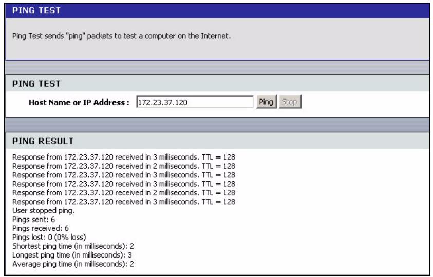
Figure 86 Tool: Ping
The following table describes the labels in this screen.
Table 46 Tools: Ping
| LABEL | DESCRIPTION |
| Ping Test | |
| Host Name or Ping Address | Enter the IP address or the domain name of the Ethernet device to which you want to test the connection. |
| Ping | Click Ping to start the connection test. The ping test will not end until you click Stop. |
| Stop | Click Stop to terminate the ping test. |
| Ping Result | This table displays the connection test result. If the ZyXEL Device receives reply messages from an Ethernet device, the reply information is automatically displayed in this table. If the ZyXEL Device is unable to receive any response from an Ethernet device, no connection test status is displayed until you click Stop. |
CHAPTER 9 Status
This chapter describes the Status screens you use to view the system status and logs.
9.1 Device Info
Display the Device Status screen to view device information such as the system time and interface settings.
Click Status > Device Status to display the screen.
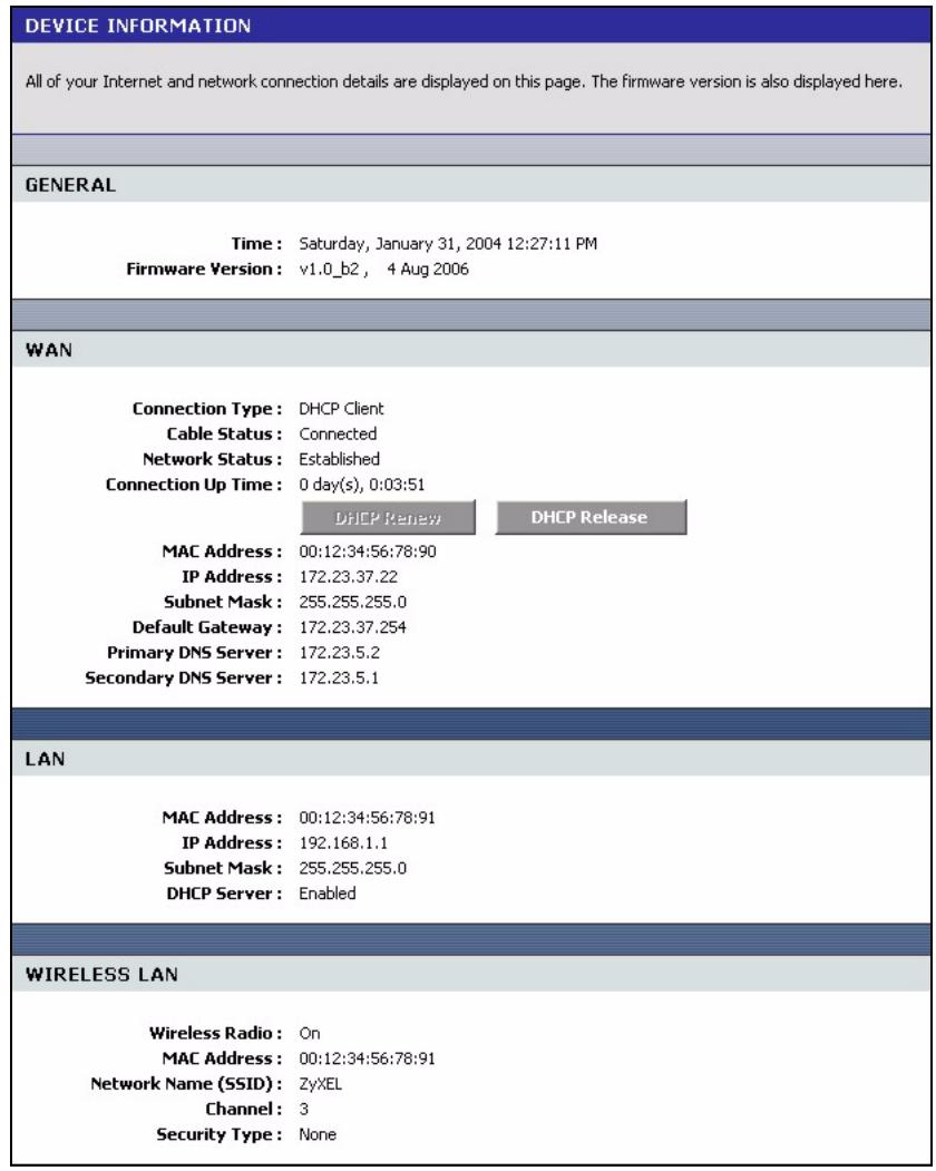
Figure 87 Status: Device Info
The following table describes the labels in this screen.
Table 47 Status: Device Information
| LABEL | DESCRIPTION |
| General | |
| Time | This field displays the current system date and time. |
| Firmware Version | This field displays the firmware version and the date created. |
| WAN | |
| Connection Type | This field displays the connection status. |
| Cable Status | This field indicates whether the Ethernet cable is connected or not. |
| Network Status | This field indicates whether a connection to the ISP is up or not. |
| Connection Up Time | This field displays the time since the connection was up. |
| DHCP Renew | This button is applicable when the ZyXEL Device uses a dynamic IP address. Click DHCP Renew to get a new dynamic IP address. |
| DHCP Release | This button is applicable when the ZyXEL Device uses a dynamic IP address. Click DHCP Release to release the current IP address. You must then click DHCP Renew to get a new IP address. |
| Connect | This button is available when the ZyXEL Device is set to use PPPoE connection type. Click Connect to establish an Internet connection using PPPoE. |
| Disconnect | This button is available when the ZyXEL Device is set to use PPPoE connection type. Click Disconnect to disconnect the Internet connection. |
| MAC Address | This field displays the MAC address of the WAN port on the ZyXEL Device. |
| IP Address | This field displays the WAN IP address. |
| Subnet Mask | This field displays the WAN subnet mask. |
| Default Gateway | This field displays the IP address of the gateway on the WAN. |
| Primary/Secondary DNS Server | This field displays the IP address(es) of the DNS server(s). |
| LAN | |
| MAC Address | This field displays the MAC address of the LAN port on the ZyXEL Device. |
| IP Address | This field displays the LAN IP address. |
| Subnet Mask | This field displays the LAN subnet mask. |
| DHCP Server | This field displays whether the DHCP server is active or not on the LAN. |
| Wireless LAN | |
| Wireless Radio | This field displays whether the wireless LAN feature is active or not. |
| MAC Address | This field displays the MAC address of the WLAN interface on the ZyXEL Device. |
| Network Name (SSID) | This field displays the name of the wireless network. |
| Channel | This field displays the wireless channel number the ZyXEL Device is using. |
| Security Type | This field displays the wireless LAN security type. |
9.2 Wireless
To view a list of wireless clients currently connected to the ZyXEL Device, click Status > Wireless.
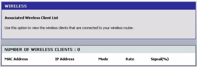
Figure 88 Status: Wireless
The following table describes the fields in this screen.
Table 48 Status: Wireless
| LABEL | DESCRIPTION |
| Number of Wireless Clients | This field displays the number of wireless clients currently connected to the ZyXEL Device. |
| MAC Address | This field displays the MAC (Media Access Control) address of an associated wireless station. Every Ethernet device has a unique MAC address. The MAC address is assigned at the factory and consists of six pairs of hexadecimal characters, for example, 00:A0:C5:00:00:02. |
| IP Address | This field displays the LAN IP address of the wireless client. |
| Mode | This field displays the wireless standard the wireless client is using. |
| Rate | This field displays the transmission rate (in megabits per second) of the wireless client. |
| Signal (%) | This field displays the relative measurement of the signal strength (in percentage). |
9.3 Logs
To view system logs, click Status > Logs.
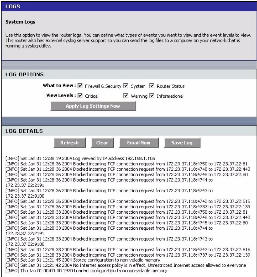
Figure 89 Status: Logs
The following table describes the labels in this screen.
Table 49 Status: Logs
| LABEL | DESCRIPTION |
| Log Options | |
| What to View | Select the type of logs to display in this screen. |
| View Levels | Select the log severity level to display in this screen. |
| Apply Log Settings Now | Click this button to save the changes in this screen. |
| Log Details | |
| Refresh | Click Refresh to update this screen. |
| Clear | Click Clear to delete all the logs. Once deleted, you cannot view the logs again. |
| Email Now | Click Email Now to send the logs to the e-mail you specified in the Tools > E-mail screen. |
| Save Log | Click Save Log to store the logs to a file on your computer. |
9.4 Statistics
To view the LAN, WAN and WLAN statistics, click Status > Statistics.
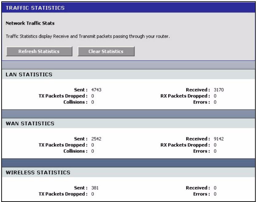
Figure 90 Status: Statistics
The following table describes the labels in this screen.
Table 50 Status: Statistics
| LABEL | DESCRIPTION |
| LAN Statistics | |
| Sent | This field displays the number of packets sent on the LAN. |
| Tx Packets Dropped | This field displays the number of transmitted packets that were dropped on the LAN. |
| Collisions | This field displays the number of packets sent with collision errors on the LAN. |
| Received | This field displays the number of packets received on the LAN. |
| Rx Packets Dropped | This field displays the number of packets received that were dropped on the LAN. |
| Errors | This field displays the number of packets received with errors on the LAN. |
| WAN Statistics | |
| Sent | This field displays the number of packets sent on the WAN. |
| Tx Packets Dropped | This field displays the number of transmitted packets that were dropped on the WAN. |
| Collisions | This field displays the number of packets sent with collision errors on the WAN. |
| Received | This field displays the number of packets received on the WAN. |
| Rx Packets Dropped | This field displays the number of packets received that were dropped on the WAN. |
| Errors | This field displays the number of packets received with errors on the WAN. |
| WLAN Statistics | |
| Sent | This field displays the number of packets sent on the WLAN. |
| Tx Packets Dropped | This field displays the number of transmitted packets that were dropped on the WLAN. |
| Received | This field displays the number of packets received on the WLAN. |
| Errors | This field displays the number of packets received with errors on the WLAN. |
CHAPTER 10 Troubleshooting
This chapter covers potential problems and the corresponding remedies.
10.1 Problems Starting Up the ZyXEL Device
Table 51 Troubleshooting Starting Up Your ZyXEL Device
| PROBLEM | CORRECTIVE ACTION |
| None of the LEDs turn on when I turn on the ZyXEL Device. | Make sure that the ZyXEL Device's power adaptor is connected to the ZyXEL Device and plugged in to an appropriate power source. Make sure that the ZyXEL Device and the power source are ZyXEL Device turned on. Turn the ZyXEL Device off and on. If the error persists, you may have a hardware problem. In this case, you should contact your vendor. |
10.2 Problems with the LAN
Table 52 Troubleshooting the LAN
| PROBLEM | CORRECTIVE ACTION |
| The LAN LEDs do not turn on. | Check your Ethernet cable connections (refer to the Quick Start Guide for details). Check for faulty Ethernet cables. |
| Make sure your computer's Ethernet Card is working properly. | |
| I cannot access the ZyXEL Device from the LAN. | If you assign the computer a static IP address, make sure that the IP address and the subnet mask of the ZyXEL Device and your computer(s) are on the same subnet. |
10.3 Problems with the WAN
Table 53 Troubleshooting the WAN
| PROBLEM | CORRECTIVE ACTION |
| The WAN LED is off. | Check the connections between the ZyXEL Device WAN port and the cable/DSL modem or Ethernet jack. |
| Check whether your cable/DSL device requires a crossover or straight-through cable. | |
| I cannot get a WAN IP address from the ISP. | In the web configurator, display the WAN screen to verify your Internet account settings. The ISP provides the WAN IP address after authenticating you. Authentication may be through the user name and password, the MAC address or the host name. The username and password are required for Internet access, make sure that you have entered the correct service type, user name and password (be sure to use the correct casing). |
| I cannot access the Internet. | Make sure the ZyXEL Device is turned on and connected to the network. Verify your WAN settings. Refer to the chapter on WAN setup. Make sure you have entered the correct user name and password. |
| The Internet connection disconnects. | If you use PPPoE, PPTP or L2TP mode, check the idle time-out setting. If the problem persists, contact your ISP. |
10.4 Problems with the WLAN
Table 54 Troubleshooting the WLAN
| PROBLEM | CORRECTIVE ACTION |
| The WLAN LED is off. | Check that the ON OFF switch is in the ON position. This switch allows you to enable or disable WLAN connection on the ZyXEL Device without having to log into the web configurator. |
| I cannot access the WLAN. | Make sure you have configured your wireless station to use the same wireless settings as the ZyXEL Device. Check that you have set the wireless station to use the same wireless security mode and/or keys. |
10.5 Problems Accessing the ZyXEL Device
Table 55 Troubleshooting Accessing the ZyXEL Device
| PROBLEM | CORRECTIVE ACTION |
| I cannot access the ZyXEL Device on the LAN. | Make sure your computer is connected to a LAN port on the ZyXEL Device. Use the ZyXEL Device's LAN IP address when configuring from the LAN. The default LAN IP address is 192.168.1.1. The IP addresses of your computer and the ZyXEL Device must be on the same subnet for LAN access. Check that traffic from your computer to the ZyXEL Device is not blocked by an access control policy or MAC address filter. |
| I cannot log into the web configurator | The username is “admin”. The default password is “1234”. The Password andUsername fields are case-sensitive. Make sure that you enter the correct password and username using the proper casing. If you have changed the password and have now forgotten it, you will need to upload the default configuration file. This restores all of the factory defaults including the password. |
10.6 Problems with Internet Access
Table 56 Troubleshooting Restricted Web Pages and Keyword Blocking
| PROBLEM | CORRECTIVE ACTION |
| Access to a restricted web page is not blocked. | Make sure that the Enable Parental Control check box is selected in the Parental Control screen. |
| Make sure that you select a category in the Parental Control screen to restrict access to web pages relevant to that category. For example, select the Gambling check box to prevent access to www.onlinegambling.com. | |
| Access to a web page with a forbidden URL is not blocked. | Make sure that you have enabled the web filter function on the ZyXEL Device. Make sure that the web site address is NOT listed in the Allowed Web Site List. |
APPENDIX A
Product Specifications
The following table is a summary of other features available.
Table 57 Hardware Features
| WLAN | The ZyXEL Device is able to connect to another draft IEEE 802.11n wireless device at up to 300 Mbps. The ZyXEL Device is also able to connect to IEEE 802.11b and IEEE 802.11g devices. |
| MIMO (Multiple Input Multiple Output) | The ZyXEL Device supports MIMO to increase both transmission speed and range of your wireless network. |
| Antenna | Three detachable (reverse SMA) 4 dBi gain |
| USB Port | USB version 1.1. Connect a USB storage device to this USB port to transfer wireless LAN settings on the ZyXEL Device to your wireless client(s) with the Windows Connect Now feature in Windows XP (SP2). |
| Ethernet ports | Auto-negotiating: 10 Mbps or 100 Mbps in either half-duplex or full-duplex mode. Auto-crossover: Use either crossover or straight-through Ethernet cables. |
| Dimensions (D x W x H) | 156 mm x 198 mm x 29.5 mm |
| Power Specification | INPUT: 100-240V, 50/60Hz, 0.5A OUTPUT: 5.0V-2.5A |
| Operation Temperature | 0° C ~ 50° C |
| Storage Temperature | -20° C ~ 60° C |
| Operation Humidity | 20% ~ 95% RH |
| Storage Humidity | 10% ~ 90% RH |
Table 58 Firmware Features
| FEATURE | DESCRIPTION |
| Draft IEEE 802.11N | Based on the draft IEEE 802.11n standard (also known as pre-N), the ZyXEL Device is able to connect to another draft IEEE 802.11n wireless device at a up to 300 Mbps. |
| Wireless LAN Security | Your ZyXEL Device supports various security methods (WEP, WPA, WPA2 with AES and IKE) to protect communication in your wireless LAN. |
| Windows Connect Now | This feature allows you to easily transfer wireless settings on your ZyXEL Device to a USB memory stick and then save the settings to wireless client computer(s). |
| StreamEngine™ | You can set this feature on the ZyXEL Device to perform intelligent and automatic traffic prioritizing for time-sensitive applications (such as voice). |
Table 58 Firmware Features
| FEATURE | DESCRIPTION |
| Network Address Translation (NAT) | Each computer on your network must have its own unique IP address. Use NAT to convert a single public IP address to multiple private IP addresses for the computers on your network. |
| Port Forwarding | If you have a server (mail or web server for example) on your network, then use this feature to let people access it from the Internet. |
| DHCP (Dynamic Host Configuration Protocol) | Use this feature to have the ZyXEL Device assign IP addresses, an IP default gateway and DNS servers to computers on your network. |
| Dynamic DNS Support | With Dynamic DNS (Domain Name System) support, you can use a fixed URL, www.zyxel.com for example, with a dynamic IP address. You must register for this service with a Dynamic DNS service provider. |
| Universal Plug and Play (UPnP) | The ZyXEL Device can communicate with other UPnP enabled devices in a network. |
| Time and Date | Get the current time and date from an external server when you turn on your ZyXEL Device. You can also set the time manually. These dates and times are then used in logs. |
| Logging and Tracing | Use packet tracing and logs for troubleshooting. You can send logs from the ZyXEL Device to an external UNIX syslog server. |
| Device Management | Use the web configurator to easily configure the rich range of features on the ZyXEL Device. |
| Firmware Upgrade | Download new firmware (when available) from the ZyXEL web site and use the web configurator, an FTP or a TFTP tool to put it on the ZyXEL Device. |
| Configuration Backup & Restoration | Make a copy of the ZyXEL Device's configuration and put it back on the ZyXEL Device later if you decide you want to revert back to an earlier configuration. |
Table 59 Default LAN and Management Settings
| Default LAN IP Address | 192.168.1.1 |
| Default Subnet Mask | 255.255.255.0 (24 bits) |
| Default LoginUsername | admin |
| Default Login Password | 1234 |
| DHCP Pool | 192.168.1.100 to 192.168.1.199 |
Appendix B Wireless LANs
Wireless LAN Topologies
This section discusses ad-hoc and infrastructure wireless LAN topologies.
Ad-hoc Wireless LAN Configuration
The simplest WLAN configuration is an independent (Ad-hoc) WLAN that connects a set of computers with wireless stations (A, B, C). Any time two or more wireless adapters are within range of each other, they can set up an independent network, which is commonly referred to as an Ad-hoc network or Independent Basic Service Set (IBSS). The following diagram shows an example of notebook computers using wireless adapters to form an Ad-hoc wireless LAN.
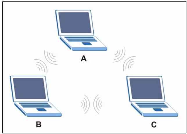
Figure 91 Peer-to-Peer Communication in an Ad-hoc Network
BSS
A Basic Service Set (BSS) exists when all communications between wireless stations or between a wireless station and a wired network client go through one access point (AP).
Intra-BSS traffic is traffic between wireless stations in the BSS. When Intra-BSS is enabled, wireless station A and B can access the wired network and communicate with each other. When Intra-BSS is disabled, wireless station A and B can still access the wired network but cannot communicate with each other.
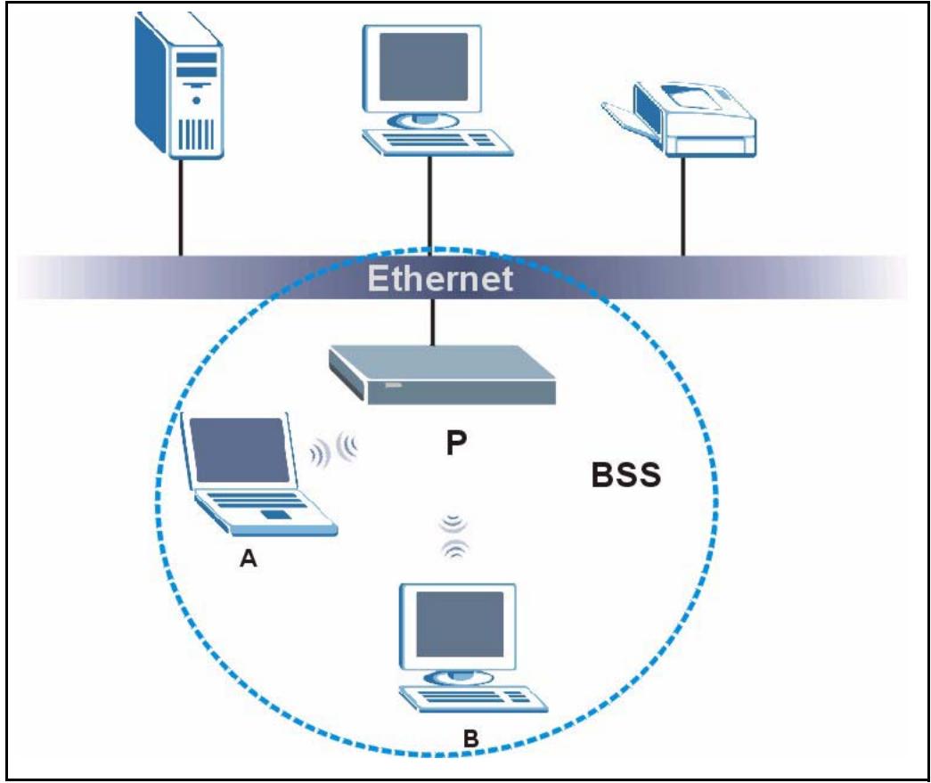
Figure 92 Basic Service Set
ESS
An Extended Service Set (ESS) consists of a series of overlapping BSSs, each containing an access point, with each access point connected together by a wired network. This wired connection between APs is called a Distribution System (DS).
This type of wireless LAN topology is called an Infrastructure WLAN. The Access Points not only provide communication with the wired network but also mediate wireless network traffic in the immediate neighborhood.
An ESSID (ESS IDentification) uniquely identifies each ESS. All access points and their associated wireless stations within the same ESS must have the same ESSID in order to communicate.
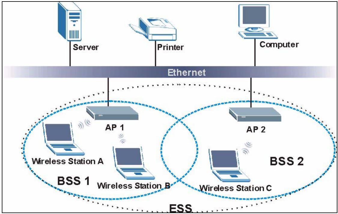
Figure 93 Infrastructure WLAN
Channel
A channel is the radio frequency(ies) used by IEEE 802.11a/b/g wireless devices. Channels available depend on your geographical area. You may have a choice of channels (for your region) so you should use a different channel than an adjacent AP (access point) to reduce interference. Interference occurs when radio signals from different access points overlap causing interference and degrading performance.
Adjacent channels partially overlap however. To avoid interference due to overlap, your AP should be on a channel at least five channels away from a channel that an adjacent AP is using. For example, if your region has 11 channels and an adjacent AP is using channel 1, then you need to select a channel between 6 or 11.
RTS/CTS
A hidden node occurs when two stations are within range of the same access point, but are not within range of each other. The following figure illustrates a hidden node. Both stations (STA) are within range of the access point (AP) or wireless gateway, but out-of-range of each other, so they cannot "hear" each other, that is they do not know if the channel is currently being used. Therefore, they are considered hidden from each other.
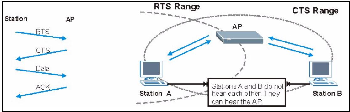
Figure 94 RTS/CTS
When station A sends data to the AP, it might not know that the station B is already using the channel. If these two stations send data at the same time, collisions may occur when both sets of data arrive at the AP at the same time, resulting in a loss of messages for both stations.
RTS/CTS is designed to prevent collisions due to hidden nodes. An RTS/CTS defines the biggest size data frame you can send before an RTS (Request To Send)/CTS (Clear to Send) handshake is invoked.
When a data frame exceeds the RTS/CTS value you set (between 0 to 2432 bytes), the station that wants to transmit this frame must first send an RTS (Request To Send) message to the AP for permission to send it. The AP then responds with a CTS (Clear to Send) message to all other stations within its range to notify them to defer their transmission. It also reserves and confirms with the requesting station the time frame for the requested transmission.
Stations can send frames smaller than the specified RTS/CTS directly to the AP without the RTS (Request To Send)/CTS (Clear to Send) handshake.
You should only configure RTS/CTS if the possibility of hidden nodes exists on your network and the "cost" of resending large frames is more than the extra network overhead involved in the RTS (Request To Send)/CTS (Clear to Send) handshake.
If the RTS/CTS value is greater than the Fragmentation Threshold value (see next), then the RTS (Request To Send)/CTS (Clear to Send) handshake will never occur as data frames will be fragmented before they reach RTS/CTS size.
Note: Enabling the RTS Threshold causes redundant network overhead that could negatively affect the throughput performance instead of providing a remedy.
Fragmentation Threshold
A Fragmentation Threshold is the maximum data fragment size (between 256 and 2432 bytes) that can be sent in the wireless network before the AP will fragment the packet into smaller data frames.
A large Fragmentation Threshold is recommended for networks not prone to interference while you should set a smaller threshold for busy networks or networks that are prone to interference.
If the Fragmentation Threshold value is smaller than the RTS/CTS value (see previously) you set then the RTS (Request To Send)/CTS (Clear to Send) handshake will never occur as data frames will be fragmented before they reach RTS/CTS size.
Preamble Type
A preamble is used to synchronize the transmission timing in your wireless network. There are two preamble modes: Long and Short.
Short preamble takes less time to process and minimizes overhead, so it should be used in a good wireless network environment when all wireless stations support it.
Select Long if you have a 'noisy' network or are unsure of what preamble mode your wireless stations support as all IEEE 802.11b compliant wireless adapters must support long preamble. However, not all wireless adapters support short preamble. Use long preamble if you are unsure what preamble mode the wireless adapters support, to ensure interpretability between the AP and the wireless stations and to provide more reliable communication in 'noisy' networks.
Select Dynamic to have the AP automatically use short preamble when all wireless stations support it, otherwise the AP uses long preamble.
Note: The AP and the wireless stations MUST use the same preamble mode in order to communicate.
IEEE 802.11g Wireless LAN
IEEE 802.11g is fully compatible with the IEEE 802.11b standard. This means an IEEE 802.11b adapter can interface directly with an IEEE 802.11g access point (and vice versa) at 11 Mbps or lower depending on range. IEEE 802.11g has several intermediate rate steps between the maximum and minimum data rates. The IEEE 802.11g data rate and modulation are as follows:
Table 60 IEEE 802.11g
| DATA RATE (MBPS) | MODULATION |
| 1 | DBPSK (Differential Binary Phase Shift Keyed) |
| 2 | DQPSK (Differential Quadrature Phase Shift Keying) |
| 5.5 / 11 | CCK (Complementary Code Keying) |
| 6/9/12/18/24/36/48/54 | OFDM (Orthogonal Frequency Division Multiplexing) |
IEEE 802.1x
In June 2001, the IEEE 802.1x standard was designed to extend the features of IEEE 802.11 to support extended authentication as well as providing additional accounting and control features. It is supported by Windows XP and a number of network devices. Some advantages of IEEE 802.1x are:
- User based identification that allows for roaming.
- Support for RADIUS (Remote Authentication Dial In User Service, RFC 2138, 2139) for centralized user profile and accounting management on a network RADIUS server.
- Support for EAP (Extensible Authentication Protocol, RFC 2486) that allows additional authentication methods to be deployed with no changes to the access point or the wireless stations.
RADIUS
RADIUS is based on a client-server model that supports authentication, authorization and accounting. The access point is the client and the server is the RADIUS server. The RADIUS server handles the following tasks:
Authentication
Determines the identity of the users.
- Authorization
Determines the network services available to authenticated users once they are connected to the network.
- Accounting
Keeps track of the client's network activity.
RADIUS is a simple package exchange in which your AP acts as a message relay between the wireless station and the network RADIUS server.
Types of RADIUS Messages
The following types of RADIUS messages are exchanged between the access point and the RADIUS server for user authentication:
- Access-Request
Sent by an access point requesting authentication.
- Access-Reject
Sent by a RADIUS server rejecting access.
- Access-Accept
Sent by a RADIUS server allowing access.
- Access-Challenge
Sent by a RADIUS server requesting more information in order to allow access. The access point sends a proper response from the user and then sends another Access-Request message.
The following types of RADIUS messages are exchanged between the access point and the RADIUS server for user accounting:
Accounting-Request
Sent by the access point requesting accounting.
- Accounting-Response
Sent by the RADIUS server to indicate that it has started or stopped accounting.
In order to ensure network security, the access point and the RADIUS server use a shared secret key, which is a password, they both know. The key is not sent over the network. In addition to the shared key, password information exchanged is also encrypted to protect the network from unauthorized access.
Types of Authentication
This appendix discusses some popular authentication types: EAP-MD5, EAP-TLS, EAP-TTLS, PEAP and LEAP.
The type of authentication you use depends on the RADIUS server or the AP. Consult your network administrator for more information.
EAP-MD5 (Message-Digest Algorithm 5)
MD5 authentication is the simplest one-way authentication method. The authentication server sends a challenge to the wireless station. The wireless station 'proves' that it knows the password by encrypting the password with the challenge and sends back the information. Password is not sent in plain text.
However, MD5 authentication has some weaknesses. Since the authentication server needs to get the plaintext passwords, the passwords must be stored. Thus someone other than the authentication server may access the password file. In addition, it is possible to impersonate an authentication server as MD5 authentication method does not perform mutual authentication. Finally, MD5 authentication method does not support data encryption with dynamic session key. You must configure WEP encryption keys for data encryption.
EAP-TLS (Transport Layer Security)
With EAP-TLS, digital certifications are needed by both the server and the wireless stations for mutual authentication. The server presents a certificate to the client. After validating the identity of the server, the client sends a different certificate to the server. The exchange of certificates is done in the open before a secured tunnel is created. This makes user identity vulnerable to passive attacks. A digital certificate is an electronic ID card that authenticates the sender's identity. However, to implement EAP-TLS, you need a Certificate Authority (CA) to handle certificates, which imposes a management overhead.
EAP-TTLS (Tunnelled Transport Layer Service)
EAP-TTLS is an extension of the EAP-TLS authentication that uses certificates for only the server-side authentications to establish a secure connection. Client authentication is then done by sending username and password through the secure connection, thus client identity is protected. For client authentication, EAP-TTLS supports EAP methods and legacy authentication methods such as PAP, CHAP, MS-CHAP and MS-CHAP v2.
PEAP (Protected EAP)
Like EAP-TTLS, server-side certificate authentication is used to establish a secure connection, then use simple username and password methods through the secured connection to authenticate the clients, thus hiding client identity. However, PEAP only supports EAP methods, such as EAP-MD5, EAP-MSCHAPv2 and EAP-GTC (EAP-Generic Token Card), for client authentication. EAP-GTC is implemented only by Cisco.
LEAP
LEAP (Lightweight Extensible Authentication Protocol) is a Cisco implementation of IEEE 802.1x.
Dynamic WEP Key Exchange
The AP maps a unique key that is generated with the RADIUS server. This key expires when the wireless connection times out, disconnects or reauthentication times out. A new WEP key is generated each time reauthentication is performed.
If this feature is enabled, it is not necessary to configure a default encryption key in the Wireless screen. You may still configure and store keys here, but they will not be used while Dynamic WEP is enabled.
Note: EAP-MD5 cannot be used with dynamic WEP key exchange
For added security, certificate-based authentications (EAP-TLS, EAP-TTLS and PEAP) use dynamic keys for data encryption. They are often deployed in corporate environments, but for public deployment, a simple user name and password pair is more practical. The following table is a comparison of the features of authentication types.
Table 61 Comparison of EAP Authentication Types
| EAP-MD5 | EAP-TLS | EAP-TTLS | PEAP | LEAP | |
| Mutual Authentication | No | Yes | Yes | Yes | Yes |
| Certificate – Client | No | Yes | Optional | Optional | No |
| Certificate – Server | No | Yes | Yes | Yes | No |
| Dynamic Key Exchange | No | Yes | Yes | Yes | Yes |
| Credential Integrity | None | Strong | Strong | Strong | Moderate |
| Deployment Difficulty | Easy | Hard | Moderate | Moderate | Moderate |
| Client Identity Protection | No | No | Yes | Yes | No |
WPA(2)
Wi-Fi Protected Access (WPA) is a subset of the IEEE 802.11i standard. WPA2 (IEEE 802.11i) is a wireless security standard that defines stronger encryption, authentication and key management than WPA.
Key differences between WPA(2) and WEP are improved data encryption and user authentication.
Encryption
Both WPA and WPA2 improve data encryption by using Temporal Key Integrity Protocol (TKIP), Message Integrity Check (MIC) and IEEE 802.1x. In addition to TKIP, WPA2 also uses Advanced Encryption Standard (AES) in the Counter mode with Cipher block chaining Message authentication code Protocol (CCMP) to offer stronger encryption.
Temporal Key Integrity Protocol (TKIP) uses 128-bit keys that are dynamically generated and distributed by the authentication server. It includes a per-packet key mixing function, a Message Integrity Check (MIC) named Michael, an extended initialization vector (IV) with sequencing rules, and a re-keying mechanism.
TKIP regularly changes and rotates the encryption keys so that the same encryption key is never used twice. The RADIUS server distributes a Pairwise Master Key (PMK) key to the AP that then sets up a key hierarchy and management system, using the pair-wise key to dynamically generate unique data encryption keys to encrypt every data packet that is wirelessly communicated between the AP and the wireless clients. This all happens in the background automatically.
WPA2 AES (Advanced Encryption Standard) is a block cipher that uses a 256-bit mathematical algorithm called Rijndael.
The Message Integrity Check (MIC) is designed to prevent an attacker from capturing data packets, altering them and resending them. The MIC provides a strong mathematical function in which the receiver and the transmitter each compute and then compare the MIC. If they do not match, it is assumed that the data has been tampered with and the packet is dropped.
By generating unique data encryption keys for every data packet and by creating an integrity checking mechanism (MIC), TKIP makes it much more difficult to decode data on a Wi-Fi network than WEP, making it difficult for an intruder to break into the network.
The encryption mechanisms used for WPA and WPA-PSK are the same. The only difference between the two is that WPA-PSK uses a simple common password, instead of user-specific credentials. The common-password approach makes WPA-PSK susceptible to brute-force password-guessing attacks but it's still an improvement over WEP as it employs an easier-to-use, consistent, single, alphanumeric password.
User Authentication
WPA or WPA2 applies IEEE 802.1x and Extensible Authentication Protocol (EAP) to authenticate wireless clients using an external RADIUS database.
If both an AP and the wireless clients support WPA2 and you have an external RADIUS server, use WPA2 for stronger data encryption. If you don't have an external RADIUS server, you should use WPA2 -PSK (WPA2 -Pre-Shared Key) that only requires a single (identical) password entered into each access point, wireless gateway and wireless client. As long as the passwords match, a wireless client will be granted access to a WLAN.
If the AP or the wireless clients do not support WPA2, just use WPA or WPA-PSK depending on whether you have an external RADIUS server or not.
Select WEP only when the AP and/or wireless clients do not support WPA or WPA2. WEP is less secure than WPA or WPA2.
10.6.1 WPA(2)-PSK Application Example
A WPA(2)-PSK application looks as follows.
1 First enter identical passwords into the AP and all wireless clients. The Pre-Shared Key (PSK) must consist of between 8 and 63 ASCII characters (including spaces and symbols).
2 The AP checks each wireless client's password and (only) allows it to join the network if the password matches.
3 The AP derives and distributes keys to the wireless clients.
4 The AP and wireless clients use the TKIP or AES encryption process to encrypt data exchanged between them.
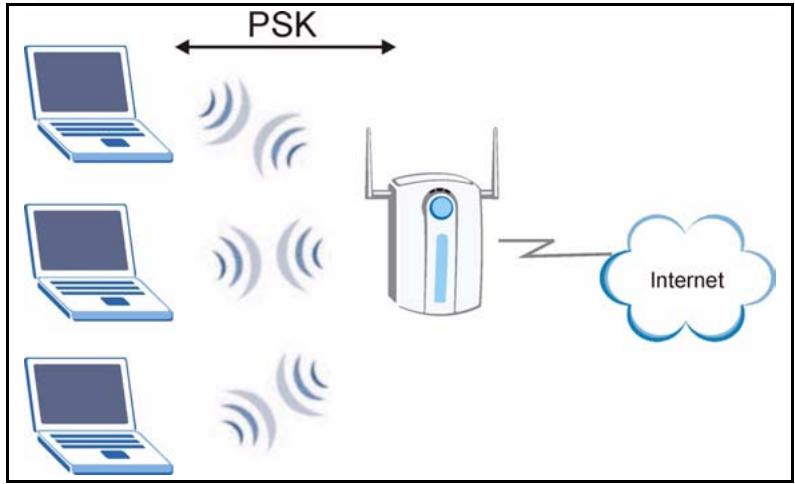
Figure 95 WPA(2)-PSK Authentication
10.6.2 WPA(2) with RADIUS Application Example
You need the IP address of the RADIUS server, its port number (default is 1812), and the RADIUS shared secret. A WPA(2) application example with an external RADIUS server looks as follows. "A" is the RADIUS server. "DS" is the distribution system.
1 The AP passes the wireless client's authentication request to the RADIUS server.
2 The RADIUS server then checks the user's identification against its database and grants or denies network access accordingly.
3 The RADIUS server distributes a Pairwise Master Key (PMK) key to the AP that then sets up a key hierarchy and management system, using the pair-wise key to dynamically generate unique data encryption keys to encrypt every data packet that is wirelessly communicated between the AP and the wireless clients.
Security Parameters Summary
Refer to this table to see what other security parameters you should configure for each Authentication Method/ key management protocol type. MAC address filters are not dependent on how you configure these security features.
Table 62 Wireless Security Relational Matrix
| AUTHENTICATION METHOD/ KEYMANAGEMENT PROTOCOL | ENCRYPTIONMETHOD | ENTERMANUAL KEY | IEEE 802.1X |
| Open | None | No | Disable |
| Enable without Dynamic WEP Key | |||
| Open | WEP | No | Enable with Dynamic WEP Key |
| Yes | Enable without Dynamic WEP Key | ||
| Yes | Disable | ||
| Shared | WEP | No | Enable with Dynamic WEP Key |
| Yes | Enable without Dynamic WEP Key | ||
| Yes | Disable | ||
| WPA | TKIP | No | Enable |
| WPA-PSK | TKIP | Yes | Enable |
| WPA2 | AES | No | Enable |
| WPA2-PSK | AES | Yes | Enable |
Appendix C Setting up Your Computer's IP Address
All computers must have a 10M or 100M Ethernet adapter card and TCP/IP installed.
Windows 95/98/Me/NT/2000/XP, Macintosh OS 7 and later operating systems and all versions of UNIX/LINUX include the software components you need to install and use TCP/IP on your computer. Windows 3.1 requires the purchase of a third-party TCP/IP application package.
TCP/IP should already be installed on computers using Windows NT/2000/XP, Macintosh OS 7 and later operating systems.
After the appropriate TCP/IP components are installed, configure the TCP/IP settings in order to "communicate" with your network.
If you manually assign IP information instead of using dynamic assignment, make sure that your computers have IP addresses that place them in the same subnet as the NBG-415N's LAN port.
Windows 95/98/Me
Click Start, Settings, Control Panel and double-click the Network icon to open the Network window
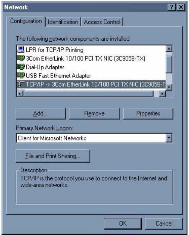
Figure 96 Windows 95/98/Me: Network: Configuration
Installing Components
The Network window Configuration tab displays a list of installed components. You need a network adapter, the TCP/IP protocol and Client for Microsoft Networks.
If you need the adapter:
1 In the Network window, click Add.
2 Select Adapter and then click Add.
3 Select the manufacturer and model of your network adapter and then click OK.
If you need TCP/IP:
1 In the Network window, click Add.
2 Select Protocol and then click Add.
3 Select Microsoft from the list of manufacturers.
4 Select TCP/IP from the list of network protocols and then click OK.
If you need Client for Microsoft Networks:
1 Click Add.
2 Select Client and then click Add.
3 Select Microsoft from the list of manufacturers.
4 Select Client for Microsoft Networks from the list of network clients and then click OK.
5 Restart your computer so the changes you made take effect.
Configuring
1 In the Network window Configuration tab, select your network adapter's TCP/IP entry and click Properties
2 Click the IP Address tab.
- If your IP address is dynamic, select Obtain an IP address automatically.
- If you have a static IP address, select Specify an IP address and type your information into the IP Address and Subnet Mask fields.
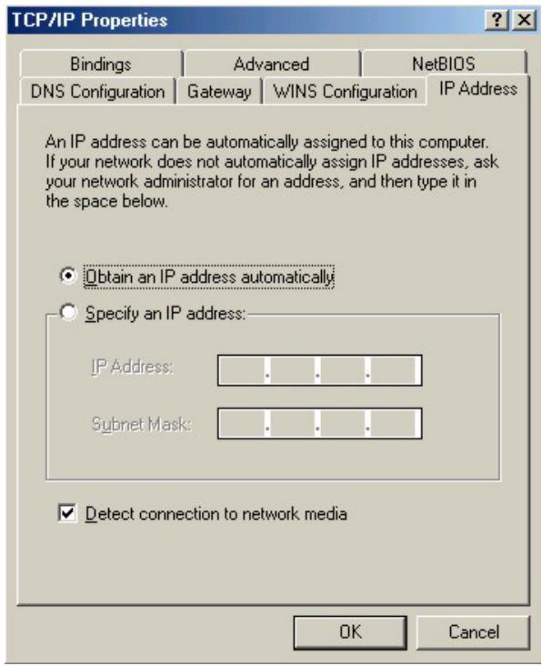
Figure 97 Windows 95/98/Me: TCP/IP Properties: IP Address
3 Click the DNS Configuration tab.
If you do not know your DNS information, select Disable DNS.
- If you know your DNS information, select Enable DNS and type the information in the fields below (you may not need to fill them all in).
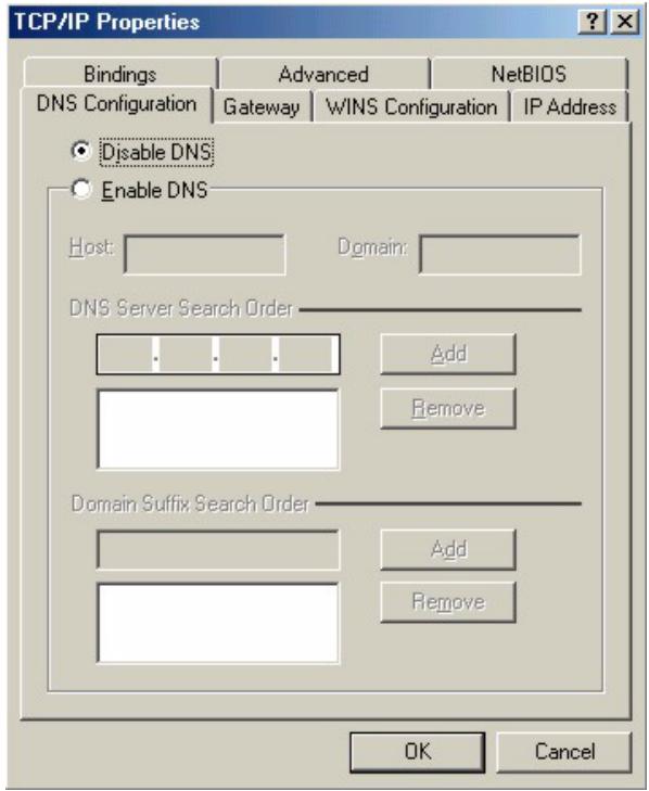
Figure 98 Windows 95/98/Me: TCP/IP Properties: DNS Configuration
4 Click the Gateway tab.
- If you do not know your gateway's IP address, remove previously installed gateways.
- If you have a gateway IP address, type it in the New gateway field and click Add.
5 Click OK to save and close the TCP/IP Properties window.
6 Click OK to close the Network window. Insert the Windows CD if prompted.
7 Turn on your NBG-415N and restart your computer when prompted.
Verifying Settings
1 Click Start and then Run.
2 In the Run window, type "winipcfg" and then click OK to open the IP Configuration window.
3 Select your network adapter. You should see your computer's IP address, subnet mask and default gateway.
Windows 2000/NT/XP
1 For Windows XP, click start, Control Panel. In Windows 2000/NT, click Start, Settings, Control Panel.
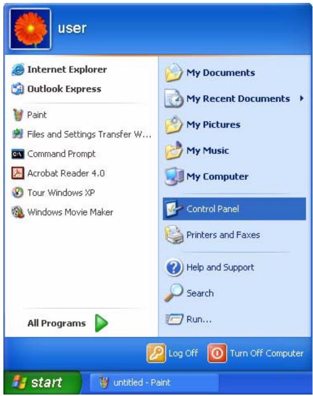
Figure 99 Windows XP: Start Menu
2 For Windows XP, click Network Connections. For Windows 2000/NT, click Network and Dial-up Connections.
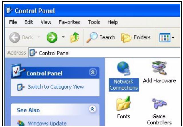
Figure 100 Windows XP: Control Panel
3 Right-click Local Area Connection and then click Properties.
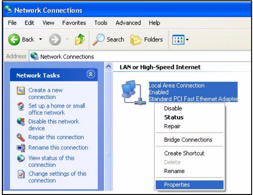
Figure 101 Windows XP: Control Panel: Network Connections: Properties
4 Select Internet Protocol (TCP/IP) (under the General tab in Win XP) and click Properties.
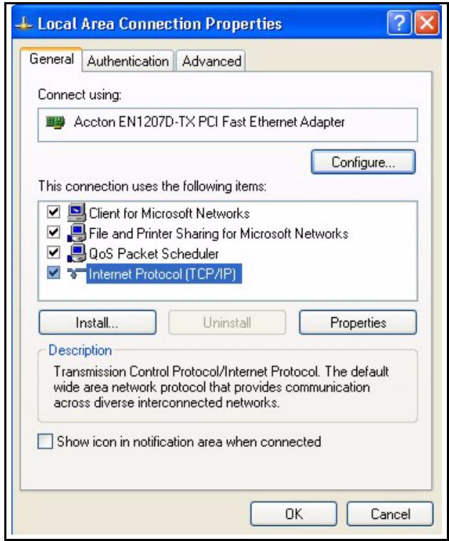
Figure 102 Windows XP: Local Area Connection Properties
5 The Internet Protocol TCP/IP Properties window opens (the General tab in Windows XP).
If you have a dynamic IP address click Obtain an IP address automatically.
- If you have a static IP address click Use the following IP Address and fill in the IP address, Subnet mask, and Default gateway fields. Click Advanced.
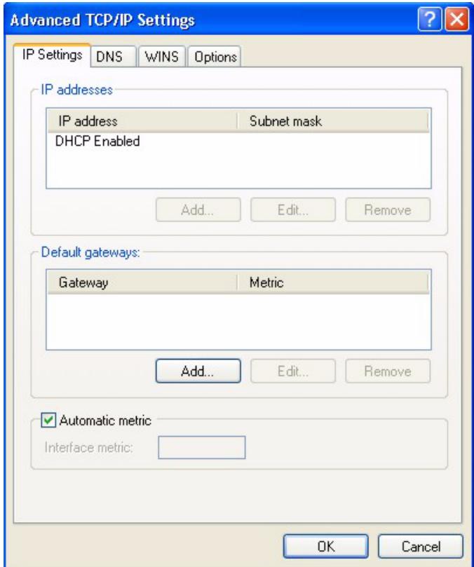
Figure 103 Windows XP: Advanced TCP/IP Settings
6 If you do not know your gateway's IP address, remove any previously installed gateways in the IP Settings tab and click OK.
Do one or more of the following if you want to configure additional IP addresses:
In the IP Settings tab, in IP addresses, click Add.
- In TCP/IP Address, type an IP address in IP address and a subnet mask in Subnet mask, and then click Add.
- Repeat the above two steps for each IP address you want to add.
- Configure additional default gateways in the IP Settings tab by clicking Add in Default gateways.
- In TCP/IP Gateway Address, type the IP address of the default gateway in Gateway. To manually configure a default metric (the number of transmission hops), clear the Automatic metric check box and type a metric in Metric.
- Click Add.
- Repeat the previous three steps for each default gateway you want to add.
- Click OK when finished.
7 In the Internet Protocol TCP/IP Properties window (the General tab in Windows XP):
- Click Obtain DNS server address automatically if you do not know your DNS server IP address(es).
- If you know your DNS server IP address(es), click Use the following DNS server addresses, and type them in the Preferred DNS server and Alternate DNS server fields.
If you have previously configured DNS servers, click Advanced and then the DNS tab to order them.
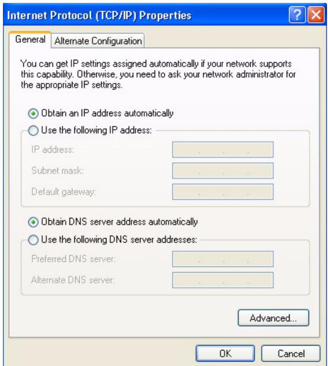
Figure 104 Windows XP: Internet Protocol (TCP/IP) Properties
8 Click OK to close the Internet Protocol (TCP/IP) Properties window.
9 Click OK to close the Local Area Connection Properties window.
10Turn on your NBG-415N and restart your computer (if prompted).
Verifying Settings
1 Click Start, All Programs, Accessories and then Command Prompt.
2 In the Command Prompt window, type "ipconfig" and then press [ENTER]. You can also open Network Connections, right-click a network connection, click Status and then click the Support tab.
Macintosh OS 8/9
1 Click the Apple menu, Control Panel and double-click TCP/IP to open the TCP/IP Control Panel.
Figure 105 Macintosh OS 8/9: Apple Menu
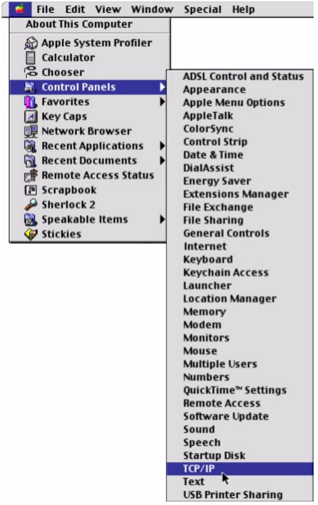
2 Select Ethernet built-in from the Connect via list.
Figure 106 Macintosh OS 8/9: TCP/IP
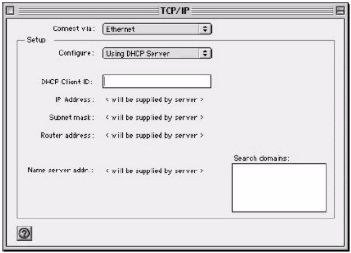
3 For dynamically assigned settings, select Using DHCP Server from the Configure: list.
4 For statically assigned settings, do the following:
From the Configure box, select Manually.
Type your IP address in the IP Address box.
- Type your subnet mask in the Subnet mask box.
- Type the IP address of your NBG-415N in the Router address box.
5 Close the TCP/IP Control Panel.
6 Click Save if prompted, to save changes to your configuration.
7 Turn on your NBG-415N and restart your computer (if prompted).
Verifying Settings
Check your TCP/IP properties in the TCP/IP Control Panel window.
Macintosh OS X
1 Click the Apple menu, and click System Preferences to open the System Preferences window.
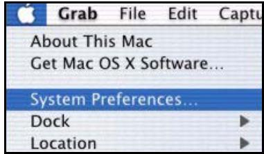
Figure 107 Macintosh OS X: Apple Menu
2 Click Network in the icon bar.
- Select Automatic from the Location list.
- Select Built-in Ethernet from the Show list.
- Click the TCP/IP tab.
3 For dynamically assigned settings, select Using DHCP from the Configure list.
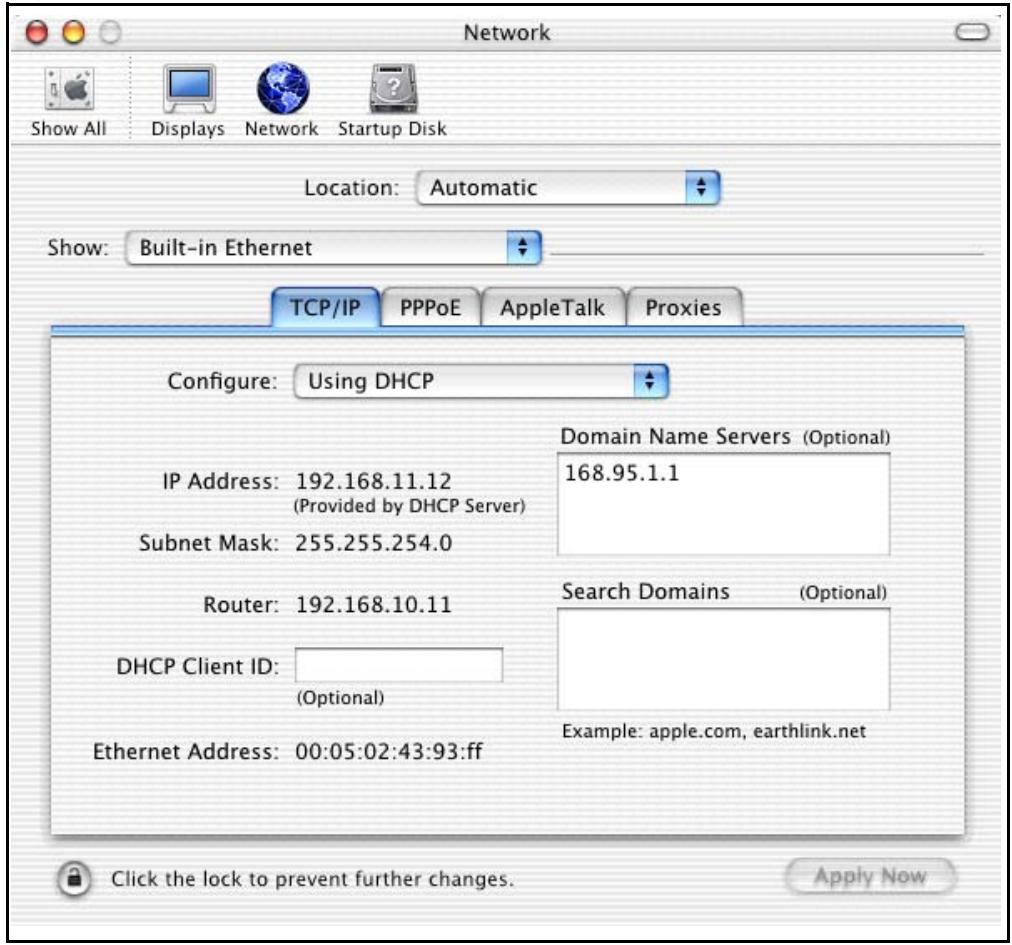
Figure 108 Macintosh OS X: Network
4 For statically assigned settings, do the following:
From the Configure box, select Manually.
- Type your IP address in the IP Address box.
- Type your subnet mask in the Subnet mask box.
- Type the IP address of your NBG-415N in the Router address box.
5 Click Apply Now and close the window.
6 Turn on your NBG-415N and restart your computer (if prompted).
Verifying Settings
Check your TCP/IP properties in the Network window.
Index
Numerics
802.11 Mode 61
content filtering 87
CTS (Clear to Send) 131
Customer Support 7
A
access control 83
activate WLAN, disable WLAN 61
Address Assignment 42, 43
address restricted 94
ALG 76, 93
AP (Access Point) 130
application
Internet sharing network 22
wireless network 23
Application Layer Gateway 76
authentication 64, 67
B
beacon period 98
BSS 128
C
CA 135
Certificate Authority 135
certifications 3
notices 4
change login password 29, 33
Channel 130
Interference 130
Configuration 56
configuration
reset 111
restore 109
save 108
configuration save 28
connection test 114
D
Daylight Saving Time See DST
default password 26
default user name 26
Delivery Traffic Indication Message see DTIM
DeMilitarized Zone See DMZ
Denial of Service 93
device information 116
device management tips 23
device reset 30, 111
device restart 111
DHCP 56, 113
address range 56
always broadcast 57
lease time 57
setup 56
DHCP reservation 57
diagnostic 114
disclaimer 2
Distribution System see DS
DMZ 93
Domain Name 43, 74
DS 99
DST 106
DTIM 99
Dynamic DNS 113
Dynamic WEP Key Exchange 135
E
EAP Authentication 134
ECHO 74
email logs 106
Encryption 136
endpoint independent 93
ESS 129
ESSID (Extended Service Set Identification) 61
Extended Service Set 129
F
FCC interference statement 3 filter setup 83
Finger 74
firewall
firmware upgrade 111
Fragmentation Threshold 131
fragmentation threshold 98
FTP 74, 113
G
game hosting 72
general WLAN settings 60
getting started 22
graphics icons key 21
H
Hidden Node 130
HTTP 74
1
IBSS 128
IEEE 802.11g 132
IEEE 802.1x65
inbound filter 96
Independent Basic Service Set 128
Internet access setup 32
IP Address 42, 54
L
L2TP 49
LAN setup 52
LED descriptions 24
load configuration 109
login 26
default password 26
defaultusername26
login accounts 102
logs 118
M
MAC address authentication 67
MAC address cloning 45
MAC address filtering 91
MAC filter 91
maximum idle time 48, 49, 51
Maximum Transmission Unit see MTU
MTU 45
N
NAT endpoint filtering 93
address restricted 94
endpoint independent 93
port and address restricted 94
Network Management 74
Network Time Protocol see NTP
NNTP 74
NTP 106
P
password change 29
Ping 114
Point-to-Point Tunneling Protocol 74
POP3 74
port and address restricted 94
portforwarding72,73
port trigger 76
PPPoE 46
PPTP 48,74
Preamble Mode 132
Private IP Address 42
product registration 6
Q
Quick Start Guide 21
R
Radio frequency 61
RADIUS 133
Shared Secret Key 134
RADIUS Message Types 133
RADIUS Messages 133
RADIUS settings 65
Real Time Streaming Protocol See RTSP
reboot device 111
reconnect mode 48, 49, 51
registration
product 6
Related Documentation 21
RESET 30
reset configuration 111
reset device 111
reset the ZyXEL Device 30
reset to the factory defaults 30, 111
restore configuration 109
RIPSee Routing Information Protocol 54
Route Settings 53
routing 81
Routing Information Protocol 54
RTS (Request To Send) 131
RTS (Request To Send) threshold 98
RTS Threshold 130, 131
RTSP 96
s
safety warnings 5
save configuration 28, 108
schedule setup 99
Security Parameters 138
Service Type 123
Services 74
set system time and date 33, 104
setup wizard 32
access control 83
Internet access 32
wireless security setup 39
SMTP 74
SNMP 74
special applications 77
SPI 93
Stateful packet inspection see SPI
static DHCP 57
static route 81
statistics 120
status 116
device info 116
logs 118
statistics 120
wireless 118
StreamEngine 78
Subnet Mask 54
support CD 21
syntax conventions 20
system time and date 33, 104
T
test connection 114
time zone 105
trademarks 2
traffic priority 78
transfer wireless settings 68
transmission rate 61
trigger port 76
U
Universal Plug and Play see UPnP
upgrade firmware 111
UPnP 102
USB port 68
Use Authentication 137
using the RESET button 30
V
view logs 118
virtual server 73
W
Wake-on-LAN see WOL
WAN setup 42
Dynamic IP 43
L2TP 49
PPPoE 46
PPTP 48
static IP 45
warranty 6
note 6
WDS 99
web configurator
common screen buttons 28
language 104
login 26
menu summary 28
screen resolution recommended 26
web browser version recommended 26
web filter 90
WEP (Wired Equivalent Privacy) 63
Windows Connect Now 68
wireless client setup 68
Wireless Distribution System see WDS
wireless LAN status 118
wireless LAN switch 61
WLAN
Interference 130
Security Parameters 138
WLAN security 62
WEP 62
WPA-Enterprise 65
WPA-Personal 64
WLAN setup 60
advanced 98
beacon period 98
fragmentation threshold 98
general 60
security 62
WLAN status 61
WOL 96
WPA mode 65, 67
WPA, WPA2 136