G-570S - Router ZYXEL - Free user manual and instructions
Find the device manual for free G-570S ZYXEL in PDF.

User questions about G-570S ZYXEL
0 question about this device. Answer the ones you know or ask your own.
Ask a new question about this device
Download the instructions for your Router in PDF format for free! Find your manual G-570S - ZYXEL and take your electronic device back in hand. On this page are published all the documents necessary for the use of your device. G-570S by ZYXEL.
USER MANUAL G-570S ZYXEL
About This User's Guide
Intended Audience
This manual is intended for people who want to configure the ZyXEL Device using the web configurator. You should have at least a basic knowledge of TCP/IP networking concepts and topology.
Related Documentation
- Quick Start Guide
The Quick Start Guide is designed to help you get up and running right away. It contains information on setting up your network and configuring for Internet access.
Web Configurator Online Help
Embedded web help for descriptions of individual screens and supplementary information.
Command Reference Guide
The Command Reference Guide explains how to use the Command-Line Interface (CLI) and CLI commands to configure the ZyXEL Device.

It is recommended you use the web configurator to configure the ZyXEL Device.
- Supporting Disk
Refer to the included CD for support documents.
ZyXEL Web Site
Please refer to www.zyxel.com for additional support documentation and product certifications.
User Guide Feedback
Help us help you. Send all User Guide-related comments, questions or suggestions for improvement to the following address, or use e-mail instead. Thank you!
The Technical Writing Team,
ZyXEL Communications Corp.,
6 Innovation Road II,
Science-Based Industrial Park,
Hsinchu, 300, Taiwan.
E-mail: techwriters@zyxel.com.tw
Document Conventions
Warnings and Notes
These are how warnings and notes are shown in this User's Guide.

Warnings tell you about things that could harm you or your device.

Notes tell you other important information (for example, other things you may need to configure or helpful tips) or recommendations.
Syntax Conventions
- The G-570S may be referred to as the "ZyXEL Device", the "device", the "system" or the "product" in this User's Guide.
- Product labels, screen names, field labels and field choices are all in bold font.
- A key stroke is denoted by square brackets and uppercase text, for example, [ENTER] means the "enter" or "return" key on your keyboard.
- “Enter” means for you to type one or more characters and then press the [ENTER] key. "Select" or "choose" means for you to use one of the predefined choices.
- A right angle bracket (>) within a screen name denotes a mouse click. For example, Maintenance > Log > Log Setting means you first click Maintenance in the navigation panel, then the Log sub menu and finally the Log Setting tab to get to that screen.
- Units of measurement may denote the "metric" value or the "scientific" value. For example, "k" for kilo may denote "1000" or "1024", "M" for mega may denote "1000000" or "1048576" and so on.
Icons Used in Figures
Figures in this User's Guide may use the following generic icons. The ZyXEL Device icon is not an exact representation of your device.
| ZyXEL Device | Computer | Notebook computer |
| Server | DSLAM | Firewall |
| Telephone | Switch | Router |
SafetyWarnings

For your safety, be sure to read and follow all warning notices and instructions.
- Do NOT use this product near water, for example, in a wet basement or near a swimming pool.
- Do NOT expose your device to dampness, dust or corrosive liquids.
- Do NOT store things on the device.
- Do NOT install, use, or service this device during a thunderstorm. There is a remote risk of electric shock from lightning.
- Connect ONLY suitable accessories to the device.
- Do NOT open the device or unit. Opening or removing covers can expose you to dangerous high voltage points or other risks. ONLY qualified service personnel should service or disassemble this device. Please contact your vendor for further information.
- Make sure to connect the cables to the correct ports.
- Place connecting cables carefully so that no one will step on them or stumble over them.
- Always disconnect all cables from this device before servicing or disassembling.
- Use ONLY an appropriate power adaptor or cord for your device. Connect it to the right supply voltage (for example, 110V AC in North America or 230V AC in Europe).
- Do NOT allow anything to rest on the power adaptor or cord and do NOT place the product where anyone can walk on the power adaptor or cord.
- Do NOT use the device if the power adaptor or cord is damaged as it might cause electrocution.
- If the power adaptor or cord is damaged, remove it from the device and the power source.
- Do NOT attempt to repair the power adaptor or cord. Contact your local vendor to order a new one.
- Do not use the device outside, and make sure all the connections are indoors. There is a remote risk of electric shock from lightning.
- Do NOT obstruct the device ventilation slots, as insufficient airflow may harm your device.
- Antenna Warning! This device meets ETSI and FCC certification requirements when using the included antenna(s). Only use the included antenna(s).
- If you wall mount your device, make sure that no electrical lines, gas or water pipes will be damaged.
This product is recyclable. Dispose of it properly.

Contents Overview
Introduction and Wizards 21
Introducing the ZyXEL Device 23
Introducing the Web Configurator 31
Wizards 35
Advanced 43
Navigating the Advanced Screens 45
Status Screens 47
System Screen 51
Wireless Screens 55
Management and Troubleshooting 87
Management Screens 89
Troubleshooting 95
Appendices and Index 99
Table of Contents
About This User's Guide 3
Document Conventions 4
SafetyWarnings 6
Contents Overview 9
Table of Contents 11
List of Figures 15
List of Tables 19
Part I: Introduction and Wizards 21
Chapter 1 Introducing the ZyXEL Device 23
1.1 Overview 23
1.2 Applications for the ZyXEL Device 23
1.2.1 Access Point for Internet Access 23
1.2.2 Corporate Network Access Application 24
1.2.3 Wireless Client Application 24
1.2.4 Bridge / Repeater 25
1.2.5 Access Point and Repeater 26
1.3 Ways to Manage the ZyXEL Device 26
1.4 Good Habits for Managing the ZyXEL Device 27
1.5 LEDs 27
1.6 Management Computer Setup 28
1.6.1 Wired Connection 28
1.6.2 Wireless Connection 28
1.7 Restarting the ZyXEL Device 29
1.8 Resetting the ZyXEL Device 29
1.8.1 Methods of Restoring Factory-Defaults 29
Chapter 2 Introducing the Web Configurator 31
2.1 Web Configurator Overview 31
2.2 Accessing the Web Configurator 31
Chapter 3
Wizards 35
3.1 Using the Wizards 35
3.1.1 Wizard: Basic Settings 35
3.1.2 Wizard: Wireless Settings 36
3.1.3 Wizard: Security Settings 37
3.1.4 Wizard: Confirm Your Settings 40
Part II: Advanced 43
Chapter 4
Navigating the Advanced Screens 45
4.0.1 Navigation Panel 46
Chapter 5
Status Screens 47
5.1 System Status 47
5.1.1 Statistics 48
5.1.2 Association List 49
Chapter 6
System Screen 51
6.1 TCP/IP Parameters 51
6.1.1 IP Address Assignment 51
6.1.2 IP Address and Subnet Mask 51
6.2 System Settings 52
Chapter 7
Wireless Screens 55
7.1 Wireless Network Overview 55
7.2 Wireless Security Overview 56
7.2.1 SSID 56
7.2.2 MAC Address Filter 56
7.2.3 User Authentication 56
7.2.4 Encryption 57
7.2.5 One-Touch Intelligent Security Technology (OTIST) 58
7.3 Wireless Performance Overview 58
7.3.1 Quality of Service (QoS) 58
7.4 Additional Wireless Terms 58
7.5 Quality of Service 59
7.5.1 WMM QoS 59
7.6 Configuring Wireless 60
7.6.1 Access Point Mode 60
7.6.2 Wireless Client Mode 62
7.6.3 The Site Survey Window 64
7.6.4 Bridge Mode 65
7.6.5 AP+Repeater Mode 69
7.7 Configuring Wireless Security 72
7.7.1 Wireless Security: Disable 73
7.7.2 Wireless Security: WEP 73
7.7.3 Wireless Security: WPA(2)-PSK 75
7.7.4 Wireless Security: WPA(2) 75
7.7.5 Wireless Security: IEEE 802.1x 77
7.8 MAC Filter 78
7.9 OTIST 81
7.9.1 Enabling OTIST 81
7.9.2 Starting OTIST 83
7.9.3 Notes on OTIST 84
Part III: Management and Troubleshooting 87
Chapter 8 Management Screens. 89
8.1 Maintenance Overview 89
8.2 Password 89
8.3 Logs 90
8.4 Configuration File 91
8.4.1 Backup Configuration 91
8.4.2 Restore Configuration 92
8.4.3 Back to Factory Defaults 93
8.5 F/W Upload Screen 93
Chapter 9 Troubleshooting 95
9.1 Power, Hardware Connections, and LEDs 95
9.2 ZyXEL Device Access and Login 96
9.3 Internet Access 98
Part IV: Appendices and Index 99
Appendix A Product Specifications 101
Appendix B Setting up Your Computer's IP Address 107
Appendix C Pop-up Windows, JavaScripts and Java Permissions 123
Appendix D Wireless LANs 129
Appendix E Customer Support 143
Appendix F Legal Information 147
Index 151
List of Figures
Figure 1 Internet Access Application 24
Figure 2 Corporate Network Application 24
Figure 3 Wireless Client Application 25
Figure 4 Bridge Application 25
Figure 5 Bridge Repeater Application 26
Figure 6 AP+Repeater Application 26
Figure 7 LEDs 27
Figure 8 Wired Connection 28
Figure 9 Wireless Connection 28
Figure 10 Web Configurator Address 32
Figure 11 Login Screen 32
Figure 12 Language Screen 32
Figure 13 Select Wizard or Advanced Setup Screen 33
Figure 14 Wizard: Basic Settings 36
Figure 15 Wizard: Wireless Settings 37
Figure 16 Setup Wizard 3: Disable 38
Figure 17 Wizard 3: WEP 39
Figure 18 Wizard 3: WPA(2)-PSK 40
Figure 19 Wizard: Confirm Your Settings 41
Figure 20 Status Screen 45
Figure 21 Status 47
Figure 22 Status: View Statistics 49
Figure 23 Status: View Association List 50
Figure 24 Status: View Association List: Wireless Client Mode 50
Figure 25 System Settings 52
Figure 26 Example of a Wireless Network 55
Figure 27 Wireless Settings: Access Point 60
Figure 28 Wireless Settings: Wireless Client 63
Figure 29 Wireless Client Mode: the Site Survey Screen 64
Figure 30 Bridging Example 66
Figure 31 Bridge Loop: Two Bridges Connected to Hub 66
Figure 32 Bridge Loop: Bridge Connected to Wired LAN 67
Figure 33 Wireless Settings: Bridge 67
Figure 34 Wireless Settings: AP+Repeater 70
Figure 35 Wireless Security: Disable 73
Figure 36 Wireless Security: WEP 74
Figure 37 Wireless Security: WPA(2)-PSK 75
Figure 38 Wireless Security: WPA(2) 76
Figure 39 Wireless Security: 802.1x 77
Figure 40 MAC Filter 80
Figure 41 OTIST 82
Figure 42 Example Wireless Client OTIST Screen 82
Figure 43 ZyXEL Device in Wireless Client Mode: OTIST Screen 83
Figure 44 Security Key 83
Figure 45 OTIST in Progress (AP) 84
Figure 46 OTIST in Progress (Client) 84
Figure 47 No AP with OTIST Found 84
Figure 48 Start OTIST? 84
Figure 49 Management: Password 89
Figure 50 Management: Logs 90
Figure 51 Management: Configuration File 91
Figure 52 Configuration Upload Successful 92
Figure 53 Network Temporarily Disconnected 92
Figure 54 Configuration Upload Error 93
Figure 55 Reset Warning Message 93
Figure 56 Management: F/W Upload 93
Figure 57 Firmware Upgrading Screen 94
Figure 58 Network Temporarily Disconnected 94
Figure 59 Firmware Upload Error 94
Figure 60 Windows 95/98/Me: Network: Configuration 108
Figure 61 Windows 95/98/Me: TCP/IP Properties: IP Address 109
Figure 62 Windows 95/98/Me: TCP/IP Properties: DNS Configuration 110
Figure 63 Windows XP: Start Menu 111
Figure 64 Windows XP: Control Panel 111
Figure 65 Windows XP: Control Panel: Network Connections: Properties 112
Figure 66 Windows XP: Local Area Connection Properties 112
Figure 67 Windows XP: Internet Protocol (TCP/IP) Properties 113
Figure 68 Windows XP: Advanced TCP/IP Properties 114
Figure 69 Windows XP: Internet Protocol (TCP/IP) Properties 115
Figure 70 Macintosh OS 8/9: Apple Menu 116
Figure 71 Macintosh OS 8/9: TCP/IP 116
Figure 72 Macintosh OS X: Apple Menu 117
Figure 73 Macintosh OS X: Network 118
Figure 74 Red Hat 9.0: KDE: Network Configuration: Devices 119
Figure 75 Red Hat 9.0: KDE: Ethernet Device: General 119
Figure 76 Red Hat 9.0: KDE: Network Configuration: DNS 120
Figure 77 Red Hat 9.0: KDE: Network Configuration: Activate 120
Figure 78 Red Hat 9.0: Dynamic IP Address Setting in ifconfig-eth0 121
Figure 79 Red Hat 9.0: Static IP Address Setting in ifconfig-eth0 121
Figure 80 Red Hat 9.0: DNS Settings in resolv.conf 121
Figure 81 Red Hat 9.0: Restart Ethernet Card 121
Figure 82 Red Hat 9.0: Checking TCP/IP Properties 122
Figure 83 Pop-up Blocker 123
Figure 84 Internet Options: Privacy 124
Figure 85 Internet Options: Privacy 125
Figure 86 Pop-up Blocker Settings 125
Figure 87 Internet Options: Security 126
Figure 88 Security Settings - Java Scripting 127
Figure 89 Security Settings - Java 127
Figure 90 Java (Sun) 128
Figure 91 Peer-to-Peer Communication in an Ad-hoc Network 129
Figure 92 Basic Service Set 130
Figure 93 Infrastructure WLAN 131
Figure 94 RTS/CTS 132
Figure 95 WPA(2) with RADIUS Application Example 139
Figure 96 WPA(2)-PSK Authentication 140
List of Tables
Table 1 Front Panel LED Description 27
Table 2 Factory Defaults 29
Table 3 Global Icon Key 45
Table 4 Screens Summary 46
Table 5 Status 47
Table 6 Status: View Statistics 49
Table 7 Status: View Association List 50
Table 8 Status: View Association List: Wireless Client Mode 50
Table 9 Private IP Address Ranges 51
Table 10 System Settings 52
Table 11 Types of Encryption for Each Type of Authentication 57
Table 12 Additional Wireless Terms 58
Table 13 WMM QoS Priorities 59
Table 14 Wireless Settings: Access Point 60
Table 15 Wireless Settings: Wireless Client 63
Table 16 Wireless: the AP Survey Screen 65
Table 17 Wireless Settings: Bridge 68
Table 18 Wireless Settings: AP + Repeater 70
Table 19 Wireless Security: Disable 73
Table 20 Wireless Security: WEP 74
Table 21 Wireless Security: WPA-PSK 75
Table 22 Wireless Security: WPA(2) 76
Table 23 Wireless Security: 802.1x 78
Table 24 MAC Filter 80
Table 25 OTIST 82
Table 26 Management: Password 89
Table 27 Management: Logs 90
Table 28 Management: Configuration File: Restore Configuration 92
Table 29 Management: F/W Upload 94
Table 30 Hardware Specifications 101
Table 31 Feature Specifications 101
Table 32 Wireless Specifications 104
Table 33 Approvals 104
Table 34 Power Adaptor Specifications 105
Table 35 IEEE 802.11g 133
Table 36 Wireless Security Levels 134
Table 37 Comparison of EAP Authentication Types 137
Table 38 Wireless Security Relational Matrix 140
PART I
Introduction and
Wizards
Introducing the ZyXEL Device (23)
Introducing the Web Configurator (31)
Wizards (35)
Introducing the ZyXEL Device
This chapter introduces the main applications and features of the ZyXEL Device. It also introduces the ways you can manage the ZyXEL Device.
1.1 Overview
The ZyXEL Device is a 4-in-1 Access Point with Super G and Turbo G wireless technology. Access Point (AP), repeater, bridge and wireless client functions allow you to use the ZyXEL Device in various network deployments. Super G and Turbo G technology boost the wireless data throughput.
The ZyXEL Device Access Point (AP) allows wireless stations to communicate and/or access a wired network. It can work as a bridge and repeater to extend your wireless network. You can also use it as a wireless client to access a wired network through another AP. The ZyXEL Device uses IEEE 802.1x, WEP data encryption, WPA (Wi-Fi Protected Access), WPA2 and MAC address filtering to give mobile users highly secured wireless connectivity. Both IEEE 802.11b and IEEE 802.11g compliant wireless devices can associate with the ZyXEL Device.
In addition to being highly flexible, the ZyXEL Device is easy to install and configure.
1.2 Applications for the ZyXEL Device
Here are some application examples of how you can use your ZyXEL Device.
1.2.1 Access Point for Internet Access
The ZyXEL Device is an ideal access solution for wireless Internet connection. A typical Internet access application for your ZyXEL Device is shown as follows.
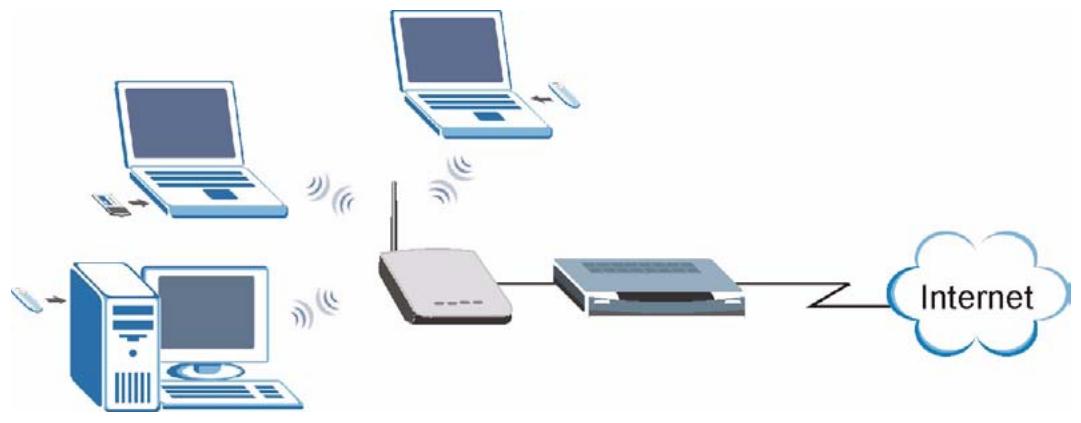
Figure 1 Internet Access Application
1.2.2 Corporate Network Access Application
In situations where users need to access corporate network resources and the Internet, the ZyXEL Device is an ideal solution for wireless stations to connect to the corporate network without expensive network cabling. Stations A, B and C can access the wired network through the ZyXEL Devices.
The following figure depicts a typical application of the ZyXEL Device in an enterprise environment. The three computers with wireless adapters are allowed to access the network resource through the ZyXEL Device after account validation by the network authentication server.
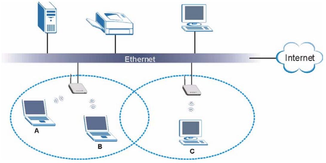
Figure 2 Corporate Network Application
1.2.3 Wireless Client Application
The ZyXEL Device can function as a wireless client to connect to a network via an Access Point (AP). The AP provides access to the wired network and the Internet.

Figure 3 Wireless Client Application
1.2.4 Bridge / Repeater
The ZyXEL Device can act as a wireless network bridge and establish wireless links with other APs. The ZyXEL Devices in the following example are using bridge mode with a star configuration. A, B, C and D are connected to independent wired networks and have bridge connections at the same time (B, C and D can communicate with A).
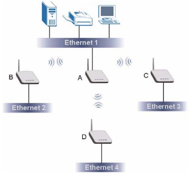
Figure 4 Bridge Application
A ZyXEL Device in bridge mode without an Ethernet connection can function as a repeater. It transmits traffic from one AP to another AP without using a wired connection. C in the following graphic repeats wireless traffic between A and B.
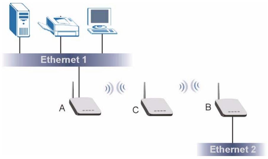
Figure 5 Bridge Repeater Application
1.2.5 Access Point and Repeater
Set the ZyXEL Device to AP+Repeater mode to have it simultaneously provide access for wireless clients and use the repeater function. This allows you to extend the coverage of your wireless network without installing Ethernet cable to connect the ZyXEL Device. In the following figure, B is in AP+Repeater mode. B functions as an AP for wireless clients C and D. B also repeats traffic between the wireless clients and AP A which is connected to the wired network. You could also set AP A to AP+Repeater mode so that wireless clients could connect to A as well.
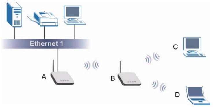
Figure 6 AP+Repeater Application
1.3 Ways to Manage the ZyXEL Device
Use any of the following methods to manage the ZyXEL Device.
- Web Configurator. This is recommended for everyday management of the ZyXEL Device using a (supported) web browser.
- Command Line Interface. Line commands are mostly used for troubleshooting by service engineers.
- FTP. Use File Transfer Protocol for firmware upgrades and configuration backup/restore.
1.4 Good Habits for Managing the ZyXEL Device
Do the following things regularly to make the ZyXEL Device more secure and to manage the ZyXEL Device more effectively.
- Change the password. Use a password that's not easy to guess and that consists of different types of characters, such as numbers and letters.
- Write down the password and put it in a safe place.
- Back up the configuration (and make sure you know how to restore it). Restoring an earlier working configuration may be useful if the device becomes unstable or even crashes. If you forget your password, you will have to reset the ZyXEL Device to its factory default settings. If you backed up an earlier configuration file, you would not have to totally reconfigure the ZyXEL Device. You could simply restore your last configuration.
1.5 LEDs

Figure 7 LEDs
The following table describes the LEDs on the ZyXEL Device.
Table 1 Front Panel LED Description
| LED | COLOR | STATUS | DESCRIPTION |
| PWR | Green | Blinking | The ZyXEL Device is not ready or rebooting. |
| On | The ZyXEL Device has rebooted successfully and is receiving power. | ||
| Off | The ZyXEL Device is not receiving power. | ||
| ETHN | Green | Blinking | The ZyXEL Device is sending/receiving data. |
| On | The ZyXEL Device has a successful 10Mbps Ethernet connection. | ||
| Amber | Blinking | The ZyXEL Device is sending/receiving data. | |
| On | The ZyXEL Device has a successful 100Mbps Ethernet connection. | ||
| Off | The ZyXEL Device does not have an Ethernet connection. | ||
| OTIST | Green | Blinking | The OTIST automatic wireless configuration is in progress. |
| On | The OTIST feature is activated on the ZyXEL Device. | ||
| Off | The OTIST feature is not activated or activated but the wireless settings have been changed. |
Table 1 Front Panel LED Description
| LED | COLOR | STATUS | DESCRIPTION |
| WLAN | Green | Blinking | The ZyXEL Device is sending or receiving data through the wireless LAN. |
| On | The ZyXEL Device is ready, but is not sending/receiving data. |
1.6 Management Computer Setup
You can connect a computer to the ZyXEL Device for management purposes either using an Ethernet connection (recommended for a first time management session) or wirelessly.
1.6.1 Wired Connection
You must prepare your computer/computer network to connect to the ZyXEL Device if you are using a wired connection. Your computer's IP address and subnet mask must be on the same subnet as the ZyXEL Device. This can be done by setting up your computer's IP address. See the appendix for details on how to set up your IP address.
The following figure shows an example of accessing your ZyXEL Device via a wired connection with an Ethernet cable.
Figure 8 Wired Connection

SSID: ZyXEL G-570S
Channel: 6
1.6.2 Wireless Connection
Ensure that the wireless stations have a compatible wireless card/adapter with the same wireless settings as the ZyXEL Device. The following figure shows how you can access your ZyXEL Device wirelessly.
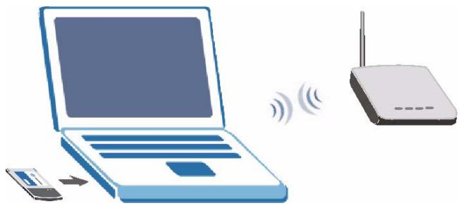
Figure 9 Wireless Connection

The wireless stations and the ZyXEL Device must use the same SSID, channel and wireless security settings for wireless communication.

If you do not enable any wireless security on your ZyXEL Device, your network traffic is visible to any wireless networking device that is within range.
1.7 Restarting the ZyXEL Device
Press and immediately release the RESET button to restart the ZyXEL Device.

Holding the RESET button in for five seconds or longer resets the device to the factory-default settings.
1.8 Resetting the ZyXEL Device
If you forget the ZyXEL Device's IP address or your password, to access the ZyXEL Device, you will need to reload the factory-default using the RESET button. Resetting the ZyXEL Device replaces the current configuration file with the factory-default configuration file. This means that you will lose all configurations that you had previously. The following parameters will be reset to the default values.
Table 2 Factory Defaults
| PARAMETER | DEFAULT VALUE |
| IP Address | 192.168.1.2 |
| Password | 1234 |
| Wireless Security | Disabled |
| SSID | ZyXEL G-570S |
1.8.1 Methods of Restoring Factory-Defaults
You can erase the current configuration and restore factory defaults in two ways:
1 Use the RESET button on the ZyXEL Device to upload the default configuration file (hold this button in for at least five seconds).
2 Use the web configurator. Click System > Management > Configuration File. From here you can restore the ZyXEL Device to its factory default settings.
Introducing the Web Configurator
This chapter describes how to configure the ZyXEL Device using the Wizard.
2.1 Web Configurator Overview
The web configurator is an HTML-based management interface that allows easy ZyXEL Device setup and management via Internet browser. Use Internet Explorer 6.0 and later or Netscape Navigator 7.0 and later versions. The recommended screen resolution is 1024 by 768 pixels.
In order to use the web configurator you need to allow:
- Web browser pop-up windows from your device. Web pop-up blocking is enabled by default in Windows XP SP (Service Pack) 2.
- JavaScripts (enabled by default).
- Java permissions (enabled by default).
See the Troubleshooting chapter for details on how to make sure these functions are allowed in Internet Explorer or Netscape Navigator.
2.2 Accessing the Web Configurator
Follow the steps below to access the web configurator, select a language, change your login password and choose a configuration method from the status screen.
1 Make sure your ZyXEL Device hardware is properly connected (refer to the Quick Start Guide).
2 Prepare your computer/computer network to connect to the ZyXEL Device (refer to the appendix on setting up your IP address).
3 Launch your web browser.
4 Type the IP address of the ZyXEL Device (192.168.1.2 is the default) in the URL bar. Press Enter.
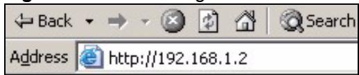
Figure 10 Web Configurator Address
5 Type "1234" (default) as the password and click Login.
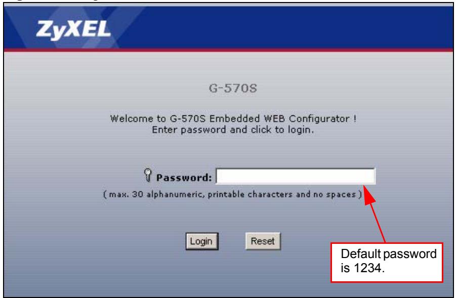
Figure 11 Login Screen
6 Select your language and click Apply.
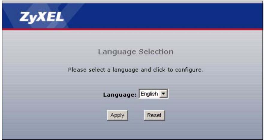
Figure 12 Language Screen
7 The following screen displays. Select Go Wizard Setup and click Apply to use the wizard setup screens for initial configuration (see Chapter 3 on page 35). Select Go Advanced Setup and click Apply to go directly to the advanced screens (see Chapter 4 on page 45).
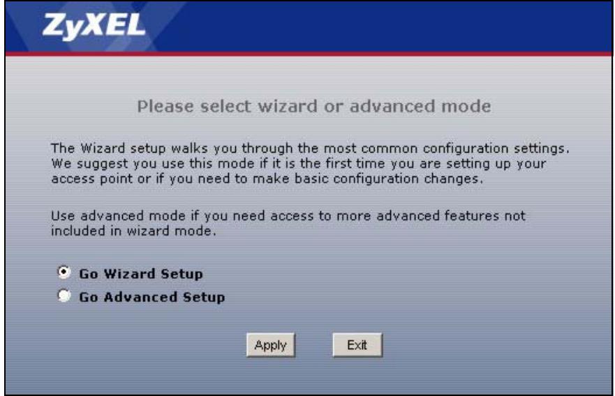
Figure 13 Select Wizard or Advanced Setup Screen
Wizards
This chapter shows you how to configure the ZyXEL Device's basic features using the wizards.
3.1 Using the Wizards
The wizards consist of a series of screens to help you configure your ZyXEL Device for wireless stations to access your wired LAN.
Use the following buttons to navigate the Wizard:
| Back | Click Back to return to the previous screen. |
| Next | Click Next to continue to the next screen. |
No configuration changes will be saved to the ZyXEL Device until you click Finish.
3.1.1 Wizard: Basic Settings
First, log into the ZyXEL Device as shown in Section 2.2 on page 31.
Click SETUP WIZARD to display the first wizard screen shown next. Refer to the System Screens chapter for more background information.
1 Enter a descriptive name to identify the device in the Ethernet network.
2 Select Obtain IP Address Automatically if you want to put the device behind a router that assigns an IP address. If you select this by mistake, use the RESET button to restore the factory default IP address.
3 Select Use fixed IP Address to give the device a static IP address. The IP address you configure here is used for management of the device (accessing the web configurator).
4 Enter a Subnet Mask appropriate to your network and the Gateway IP Address of the neighboring device, if you know it. If you do not, leave the Gateway IP Address field as 0.0.0.0.
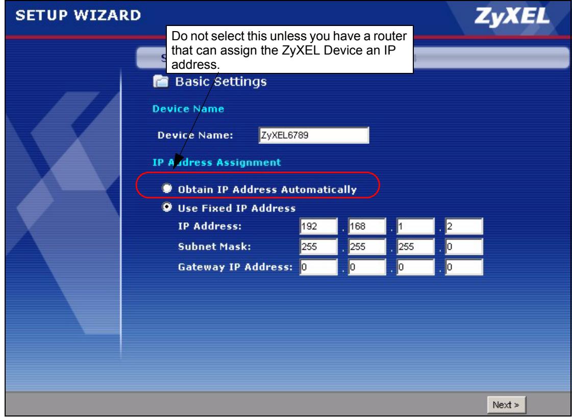
Figure 14 Wizard: Basic Settings
3.1.2 Wizard: Wireless Settings
Use this wizard screen to set up the wireless LAN. See the chapter on the wireless screens for background information.
1 The SSID is a unique name to identify the device in a wireless network. Enter up to 32 printable characters. Spaces are allowed. If you change this field on the device, make sure all wireless stations use the same SSID in order to access the network.
2 A wireless device uses a channel to communicate in a wireless network. Select a channel that is not already in use by a neighboring wireless device.

The wireless stations and this device must use the same SSID, channel and wireless security settings for wireless communication.
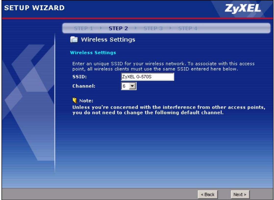
Figure 15 Wizard: Wireless Settings
3.1.3 Wizard: Security Settings
Use this screen to configure security for your wireless LAN. The screen varies depending on what you select in the Encryption Method field. Select Disable to have no wireless security configured, select WEP, or select WPA-PSK if your wireless clients support WPA-PSK. Select WPA2-PSK if your wireless clients support WPA2-PSK Go to Wireless > Security if you want WPA2, WPA or 802.1x. See Chapter 7 on page 55 for background information.
3.1.3.1 Disable
Select Disable to have no wireless LAN security configured. If you do not enable any wireless security on your device, your network is accessible to any wireless networking device that is within range.

With no wireless security a neighbor can access and see traffic in your network.
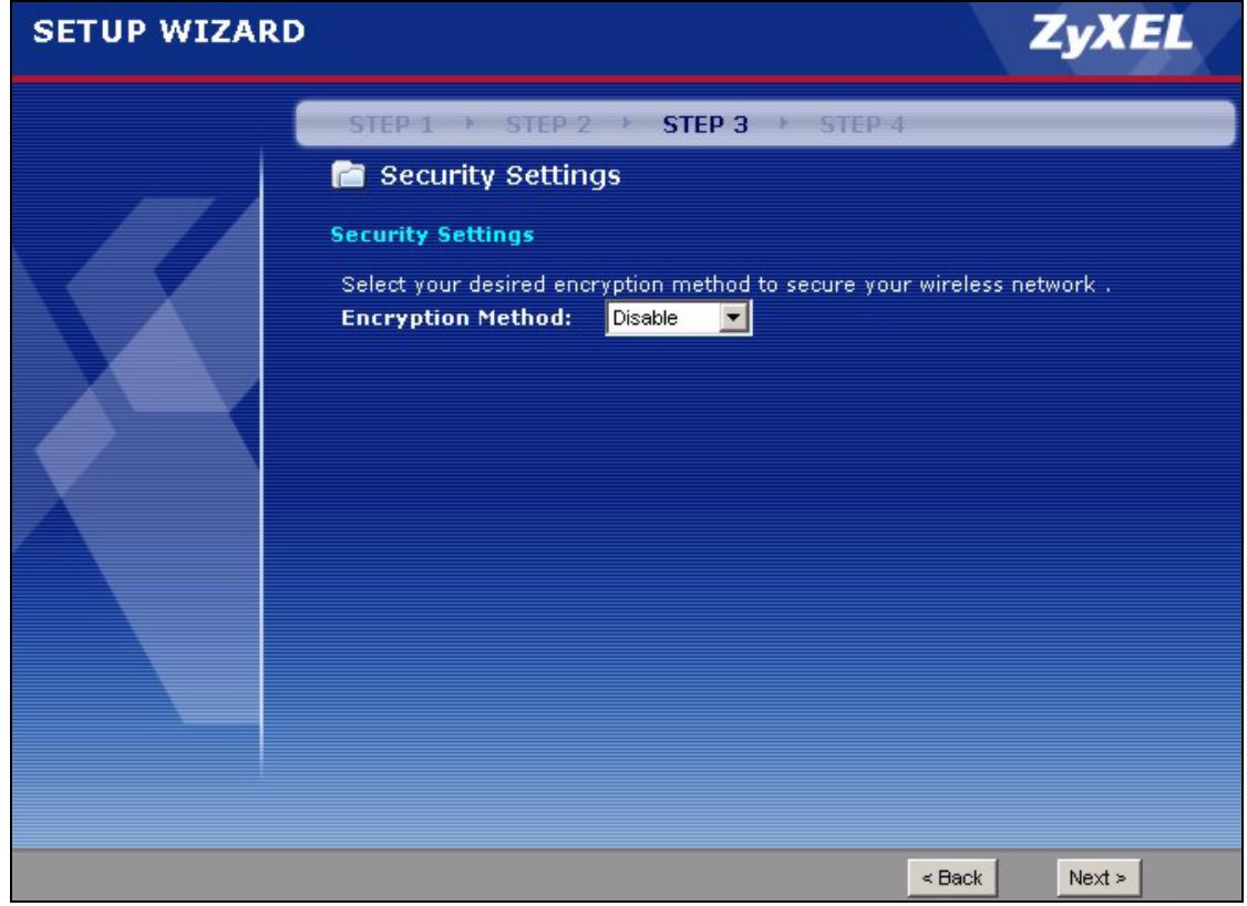
Figure 16 Setup Wizard 3: Disable
3.1.3.2 WEP
1 WEP (Wired Equivalent Privacy) encrypts data frames before transmitting over the wireless network. Select 64-bit, 128-bit or 152-bit from the WEP Encryption dropdown list box and then follow the on-screen instructions to set up the WEP keys.
2 Choose an encryption level from the drop-down list. The higher the WEP encryption, the higher the security but the slower the throughput.
3 You can generate or manually enter a WEP key.
- If you selected 64-bit or 128-bit WEP, you can enter a Passphrase (up to 32 printable characters) and click Generate. The device automatically generates WEP keys. One key displays in the Key 1 field. Go to Wireless > Security if you want to see the other WEP keys.
or
- Enter a manual key in the Key 1 field.
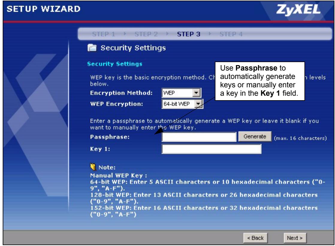
Figure 17 Wizard 3: WEP
3.1.3.3 WPA(2)-PSK
Only select WPA-PSK or WPA2-PSK if your wireless clients support it.
Type a pre-shared key from 8 to 63 ASCII characters (including spaces and symbols). This field is case-sensitive.
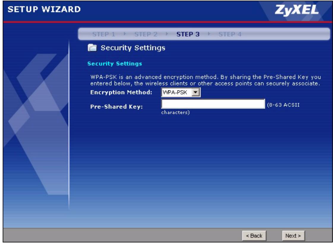
Figure 18 Wizard 3: WPA(2)-PSK
3.1.4 Wizard: Confirm Your Settings
This read-only screen shows the status of the current settings. Use the summary table to check whether what you have configured is correct. Click Finish to complete the wizard configuration and save your settings.
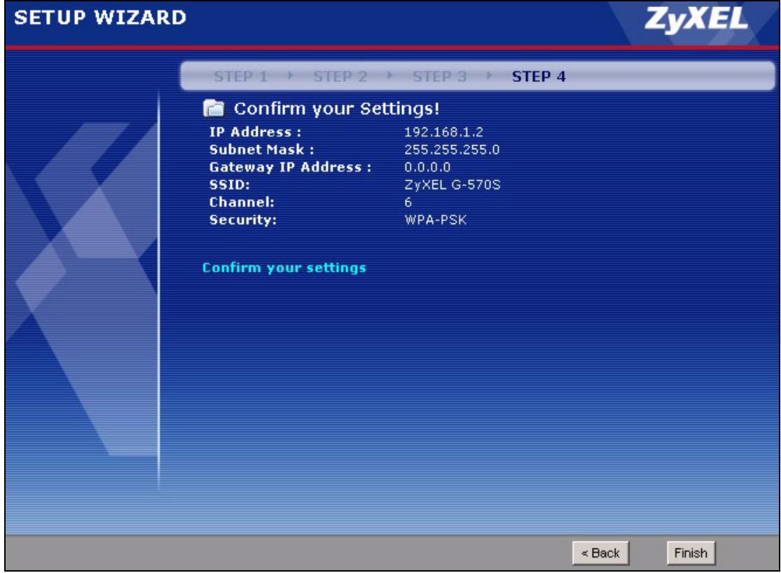
Figure 19 Wizard: Confirm Your Settings
For more detailed background information, see the rest of this User's Guide.
PART II
Advanced
Navigating the Advanced Screens (45)
Status Screens (47)
System Screen (51)
Wireless Screens (55)
Navigating the Advanced Screens
The Status screen is the first advanced screen that displays. This section explains how to navigate the advanced configuration screens. See Chapter 5 on page 47 for details about the individual screen.
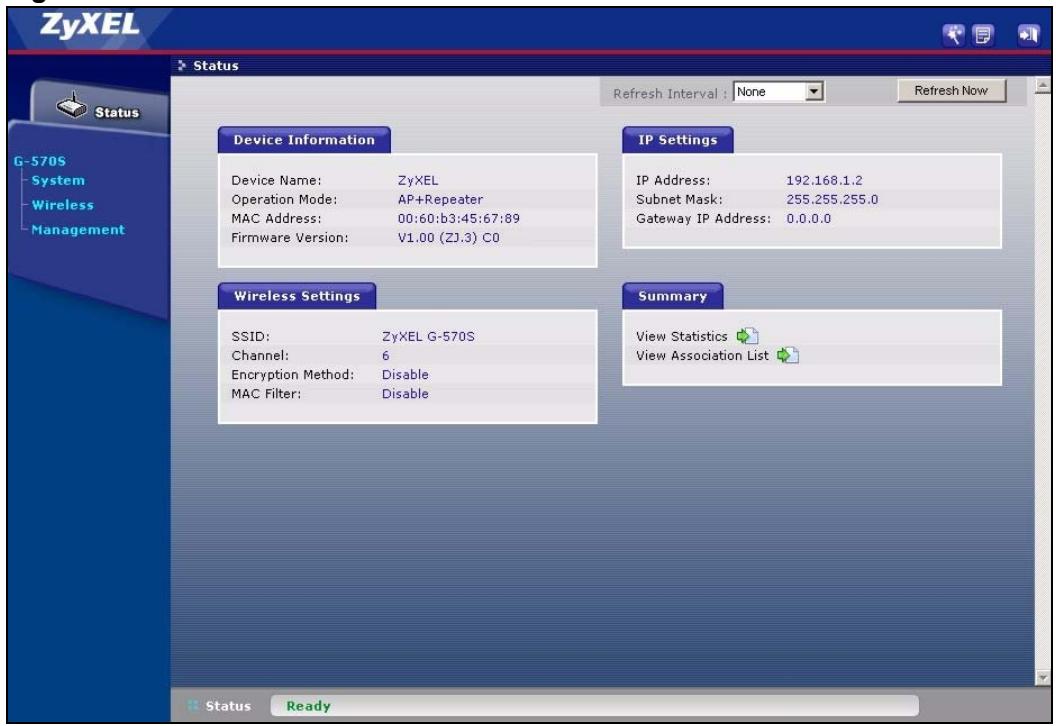
Figure 20 Status Screen
The following table describes the global web configurator icons (in the upper right corner of most screens).
Table 3 Global Icon Key
| ICON | DESCRIPTION |
| Click the Wizard icon to open the setup wizard. | |
| Click the About icon to view copyright information. | |
| Click theLogout icon at any time to exit the web configurator. Make sure you save any changes before you log out. |
4.0.1 Navigation Panel
After you enter the password, use the links on the navigation panel to go to the various advanced screens.
The following table describes the sub-menus.
Table 4 Screens Summary
| LINK | TAB | FUNCTION |
| Status | This screen shows the ZyXEL Device's general device, system and interface status information. Use this screen to access the wizard, and summary statistics tables. | |
| System | Use this screen to configure the device name and IP address assignment settings. | |
| Wireless | Wireless Settings | Use this screen to configure the wireless LAN. |
| Security | Use this screen to configure the wireless LAN's security settings. | |
| MAC Filter | Use the MAC filter screen to configure the ZyXEL Device to block or allow only certain devices to associate with the ZyXEL Device. | |
| OTIST | When the ZyXEL Device is in access point mode, this screen allows you to assign wireless clients the ZyXEL Device's wireless security settings. When the ZyXEL Device is in wireless client mode, this screen allows the ZyXEL Device to get security settings from an OTIST-enabled access point. | |
| Management | Password | Use this screen to configure the administrator password. |
| Logs | Use this screen to view logs and alert messages. | |
| Configuration | Use this screen to backup and restore the configuration or reset the factory defaults to your ZyXEL Device. | |
| F/W Upload | Use this screen to upload firmware to your ZyXEL Device. |

See the rest of this User's Guide for configuration details and background information on all features using the web configurator.
This chapter describes the Status screens.
5.1 System Status
Click Status to open the following screen. The Status screen displays a snapshot of your device's settings. You can also view network statistics and a list of wireless stations currently associated with your device. Note that these labels are READ-ONLY and are meant to be used for diagnostic purposes.
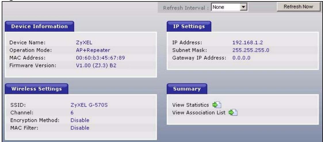
Figure 21 Status
The following table describes the labels in this screen.
Table 5 Status
| LABEL | DESCRIPTION |
| Refresh Interval | Use the drop-down list box to select how often you want the device to renew the information on this screen. |
| Refresh Now | Click this button to have the device renew the information on this screen. |
| Device Information | |
| Device Name | This is the same as the device name you entered in the first wizard screen if you entered one there. It is for identification purposes. |
| Operation Mode | This field shows whether the device is functioning as an access point, a wireless client, a bridge or an access point and repeater. |
Table 5 Status
| LABEL | DESCRIPTION |
| MAC Address | This field displays the MAC address of the device. The MAC (Media Access Control) or Ethernet address on a LAN (Local Area Network) is unique to your computer. A network interface card such as an Ethernet adapter has a hardwired address that is assigned at the factory. This address follows an industry standard that ensures no other adapter has a similar address. |
| Firmware Version | This is the firmware version and the date the firmware was created. |
| IP Settings | |
| IP Address | This is the Ethernet port IP address. |
| Subnet Mask | This is the Ethernet port subnet mask. |
| Gateway IP Address | This is the IP address of a gateway. Leave this field as 0.0.0.0 if you do not know it. |
| Wireless Settings | |
| SSID | This is the descriptive name used to identify the device in a wireless network. |
| Channel | This field displays the radio channel the device is currently using. |
| Encryption Method | This field shows the type of data encryption that is enabled on the wireless network: WEP (WEP or 802.1x) TKIP (WPA or WPA-PSK) AES (WPA2 or WPA2-PSK) TKIP + AES (WPA & WPA2 or WPA-PSK & WPA2-PSK) or Disable (no security) |
| MAC Filter | This field shows whether MAC filter is enabled or not. With MAC filtering, you can allow or deny access to the device based on the MAC addresses of the wireless stations. |
| View Statistics | Click View Statistics to see performance statistics such as number of packets sent and number of packets received. |
| View Association List | Click View Association List to show the wireless stations that are currently associated to the device. |
5.1.1 Statistics
Click View Statistics in the Status screen. This screen displays read-only information including port status and packet specific statistics. Also provided are "system up time" and "poll interval(s)". The Poll Interval(s) field is configurable.
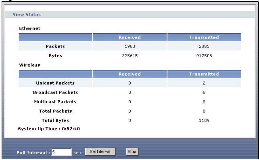
Figure 22 Status: View Statistics
The following table describes the labels in this screen.
Table 6 Status: View Statistics
| LABEL | DESCRIPTION |
| Ethernet | |
| Packets | This row displays the numbers of packets received and transmitted by the Ethernet port. |
| Bytes | This row displays the numbers of bytes received and transmitted by the Ethernet port. |
| Wireless | |
| Unicast Packets | This row displays the numbers of unicast packets received and transmitted by the wireless adapter. |
| Broadcast Packets | This row displays the numbers of broadcast packets received and transmitted by the wireless adapter. |
| Multicast Packets | This row displays the numbers of multicast packets received and transmitted by the wireless adapter. |
| Total Packets | This row displays the numbers of all types of packets received and transmitted by the wireless adapter. |
| Total Bytes | This row displays the numbers of bytes received and transmitted by the wireless adapter. |
| System Up Time | This is the total time the device has been on. |
| Poll Interval(s) | Enter the time interval for refreshing statistics. |
| Set Interval | Click this button to apply the new poll interval you entered above. |
| Stop | Click this button to stop refreshing statistics. |
5.1.2 Association List
Click Status and then the View Association List button to display the Association List screen. When the device is not in wireless client mode, this screen displays which wireless stations are currently associated to the device in the Association List screen.
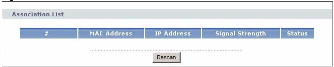
Figure 23 Status: View Association List
The following table describes the labels in this screen.
Table 7 Status: View Association List
| LABEL | DESCRIPTION |
| # | This is the index number of an associated wireless station. |
| MAC Address | This field displays the MAC address of an associated wireless station. |
| IP Address | This field displays the IP address of an associated wireless station. |
| Signal Strength | This field displays the signal strength of each associated wireless station. |
| Status | This field displays Associated for associated wireless stations. |
| Rescan | Click Rescan to check for associated wireless stations. |
When the device is in wireless client mode, this screen displays details of the access point to which the ZyXEL Device is associated.
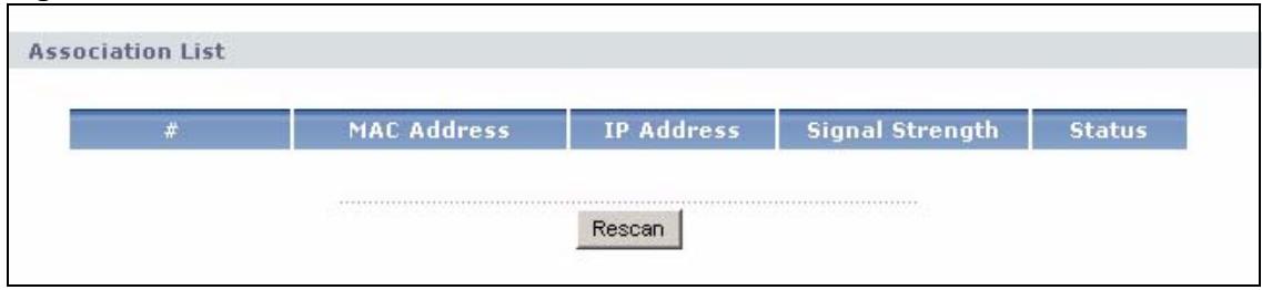
Figure 24 Status: View Association List: Wireless Client Mode
The following table describes the labels in this screen.
Table 8 Status: View Association List: Wireless Client Mode
| LABEL | DESCRIPTION |
| # | This is the index number of an associated access point. |
| MAC Address | This field displays the MAC address of the associated access point. |
| IP Address | This field displays the IP address of the associated access point. |
| Signal Strength | This field displays the signal strength of the associated access point. |
| Status | This field displays Associated for an associated access point. |
| Rescan | Click Rescan to check for associated wireless stations. |
System Screen
This chapter provides information on the System screen.
6.1 TCP/IP Parameters
6.1.1 IP Address Assignment
Every computer on the Internet must have a unique IP address. If your networks are isolated from the Internet, for instance, only between your two branch offices, you can assign any IP addresses to the hosts without problems. However, the Internet Assigned Numbers Authority (IANA) has reserved the following three blocks of IP addresses specifically for private networks.
Table 9 Private IP Address Ranges
| 10.0.0.0 | - | 10.255.255.255 |
| 172.16.0.0 | - | 172.31.255.255 |
| 192.168.0.0 | - | 192.168.255.255 |
You can obtain your IP address from the IANA, from an ISP or have it assigned by a private network. If you belong to a small organization and your Internet access is through an ISP, the ISP can provide you with the Internet addresses for your local networks. On the other hand, if you are part of a much larger organization, you should consult your network administrator for the appropriate IP addresses.

Regardless of your particular situation, do not create an arbitrary IP address; always follow the guidelines above. For more information on address assignment, please refer to RFC 1597, Address Allocation for Private Intermets and RFC 1466, Guidelines for Management of IP Address Space.
6.1.2 IP Address and Subnet Mask
Similar to the way houses on a street share a common street name, computers on a LAN share one common network number.
Where you obtain your network number depends on your particular situation. If the ISP or your network administrator assigns you a block of registered IP addresses, follow their instructions in selecting the IP addresses and the subnet mask.
If the ISP did not explicitly give you an IP network number, then most likely you have a single user account and the ISP will assign you a dynamic IP address when the connection is established. The Internet Assigned Number Authority (IANA) reserved this block of addresses specifically for private use; please do not use any other number unless you are told otherwise. Let's say you select 192.168.1.0 as the network number; which covers 254 individual addresses, from 192.168.1.1 to 192.168.1.254 (zero and 255 are reserved). In other words, the first three numbers specify the network number while the last number identifies an individual computer on that network.
Once you have decided on the network number, pick an IP address that is easy to remember, for instance, 192.168.1.2, for your device, but make sure that no other device on your network is using that IP address.
The subnet mask specifies the network number portion of an IP address. Your device will compute the subnet mask automatically based on the IP address that you entered. You don't need to change the subnet mask computed by the device unless you are instructed to do otherwise.
6.2 System Settings
Click System to open the System Settings screen.
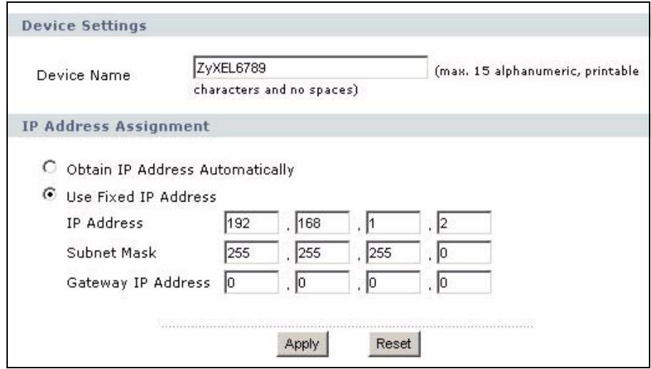
Figure 25 System Settings
The following table describes the labels in this screen.
Table 10 System Settings
| LABEL | DESCRIPTION |
| Device Name | This name can be up to 30 printable characters long. Spaces are allowed. |
| IP Address Assignment | |
| Obtain IP Address Automatically | Select this option to have your device use a dynamically assigned IP address from a router each time. |
Table 10 System Settings
| LABEL | DESCRIPTION |
| Use fixed IP address | Select this option to have your device use a static IP address. When you select this option, fill in the fields below. |
| IP Address | Enter the IP address of your device in dotted decimal notation. |
| Subnet Mask | Enter the subnet mask. |
| Gateway IP Address | Type the IP address of the gateway. The gateway is a router or switch on the same network segment as the device. The gateway helps forward packets to their destinations. Leave this field as 0.0.0.0 if you do not know it. |
| Apply | Click Apply to save your changes back to the device. |
| Reset | Click Reset to reload the previous configuration for this screen. |
Wireless Screens
This chapter discusses how to configure the wireless network settings in your ZyXEL Device. See the appendices for more detailed information about wireless networks.
7.1 Wireless Network Overview
The following figure provides an example of a wireless network.
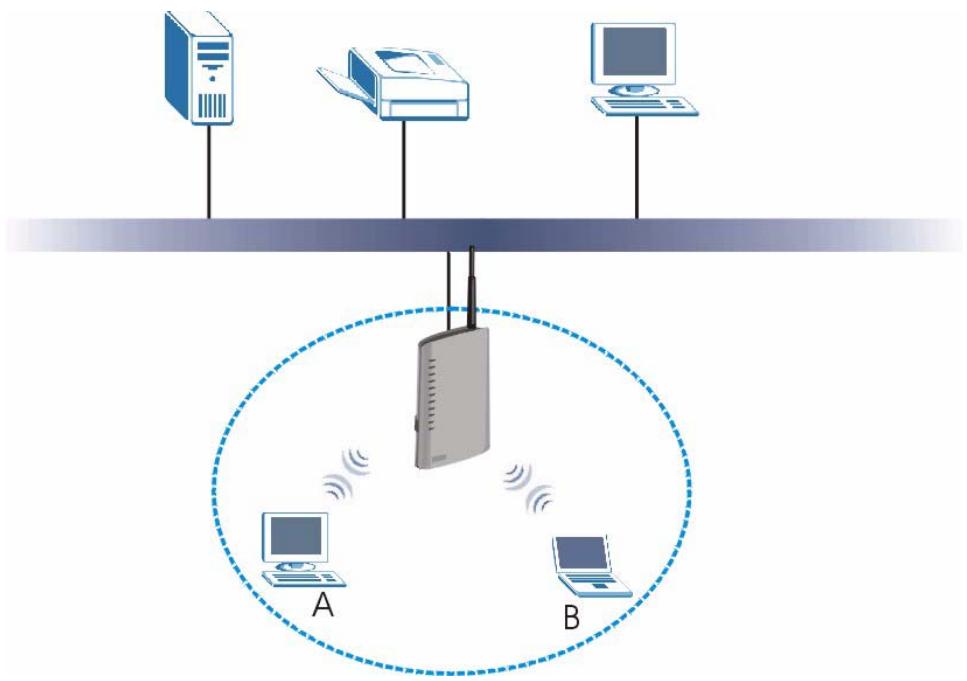
Figure 26 Example of a Wireless Network
The wireless network is the part in the blue circle. In this wireless network, devices A and B use the access point (AP) to interact with the other devices (such as the printer) or with the Internet. Your ZyXEL Device is the AP.
Every wireless network must follow these basic guidelines.
- Every device in the same wireless network must use the same SSID.
The SSID is the name of the wireless network. It stands for Service Set IDentity.
- If two wireless networks overlap, they should use a different channel.
Like radio stations or television channels, each wireless network uses a specific channel, or frequency, to send and receive information.
- Every device in the same wireless network must use security compatible with the AP. Security stops unauthorized devices from using the wireless network. It can also protect the information that is sent in the wireless network.
7.2 Wireless Security Overview
The following sections introduce different types of wireless security you can set up in the wireless network.
7.2.1 SSD
Normally, the ZyXEL Device acts like a beacon and regularly broadcasts the SSID in the area. You can hide the SSID instead, in which case the ZyXEL Device does not broadcast the SSID. In addition, you should change the default SSID to something that is difficult to guess.
This type of security is fairly weak, however, because there are ways for unauthorized wireless devices to get the SSID. In addition, unauthorized wireless devices can still see the information that is sent in the wireless network.
7.2.2 MAC Address Filter
Every device that can use a wireless network has a unique identification number, called a MAC address. A MAC address is usually written using twelve hexadecimal characters; for example, 00A0C5000002 or 00:A0:C5:00:00:02. To get the MAC address for each device in the wireless network, see the device's User's Guide or other documentation.
You can use the MAC address filter to tell the ZyXEL Device which devices are allowed or not allowed to use the wireless network. If a device is allowed to use the wireless network, it still has to have the correct information (SSID, channel, and security). If a device is not allowed to use the wireless network, it does not matter if it has the correct information.
This type of security does not protect the information that is sent in the wireless network. Furthermore, there are ways for unauthorized wireless devices to get the MAC address of an authorized device. Then, they can use that MAC address to use the wireless network.
7.2.3 User Authentication
Authentication is the process of verifying whether a wireless device is allowed to use the wireless network. You can make every user log in to the wireless network before they can use it. However, every device in the wireless network has to support IEEE 802.1x to do this.
For wireless networks, you can store the user names and passwords for each user in a RADIUS server. This is a server used in businesses more than in homes. If you do not have a RADIUS server, you cannot set up user names and passwords for your users.
Unauthorized wireless devices can still see the information that is sent in the wireless network, even if they cannot use the wireless network. Furthermore, there are ways for unauthorized wireless users to get a valid user name and password. Then, they can use that user name and password to use the wireless network.
7.2.4 Encryption
Wireless networks can use encryption to protect the information that is sent in the wireless network. Encryption is like a secret code. If you do not know the secret code, you cannot understand the message.
The types of encryption you can choose depend on the type of authentication. (See Section 7.2.3 on page 56 for information about this.)
Table 11 Types of Encryption for Each Type of Authentication
| Weakest ↓ Strongest | NO AUTHENTICATION | RADIUS SERVER |
| No Security | WPA | |
| Static WEP | ||
| WPA-PSK | ||
| WPA2-PSK | WPA2 |
For example, if the wireless network has a RADIUS server, you can choose WPA or WPA2. If users do not log in to the wireless network, you can choose no encryption, Static WEP, WPA-PSK, or WPA2-PSK.
Usually, you should set up the strongest encryption that every device in the wireless network supports. For example, suppose you have a wireless network with the ZyXEL Device and you do not have a RADIUS server. Therefore, there is no authentication. Suppose the wireless network has two devices. Device A only supports WEP, and device B supports WEP and WPA. Therefore, you should set up Static WEP in the wireless network.

It is recommended that wireless networks use WPA-PSK, WPA, or stronger encryption. The other types of encryption are better than none at all, but it is still possible for unauthorized wireless devices to figure out the original information pretty quickly.
When you select WPA2 or WPA2-PSK in your ZyXEL Device, you can also select an option (WPA compatible) to support WPA as well. In this case, if some of the devices support WPA and some support WPA2, you should set up WPA2-PSK or WPA2 (depending on the type of wireless network login) and select the WPA compatible option in the ZyXEL Device.
Many types of encryption use a key to protect the information in the wireless network. The longer the key, the stronger the encryption. Every device in the wireless network must have the same key.
7.2.5 One-Touch Intelligent Security Technology (OTIST)
With ZyXEL's OTIST, you set up the SSID and the encryption (WEP or WPA-PSK) on the ZyXEL Device. Then, the ZyXEL Device transfers them to the devices in the wireless networks. As a result, you do not have to set up the SSID and encryption on every device in the wireless network.
The devices in the wireless network have to support OTIST, and they have to be in range of the ZyXEL Device when you activate it. See Section 7.9 on page 81 for more details.
7.3 Wireless Performance Overview
The following sections introduce different ways to improve the performance of the wireless network.
7.3.1 Quality of Service (QoS)
You can turn on Wi-Fi MultiMedia (WMM) QoS to improve the performance of voice and video applications in the wireless network. QoS gives high priority to voice and video, which makes them run more smoothly. Similarly, it gives low priority to many large file downloads so that they do not reduce the quality of other applications.
7.4 Additional Wireless Terms
The following table describes wireless network terms and acronyms used in the ZyXEL Device's Web Configurator.
Table 12 Additional Wireless Terms
| TERM | DESCRIPTION |
| Intra-BSS Traffic | This describes direct communication (not through the ZyXEL Device) between two wireless devices within a wireless network. You might disable this kind of communication to enhance security within your wireless network. |
| RTS/CTS Threshold | In a wireless network which covers a large area, wireless devices are sometimes not aware of each other's presence. This may cause them to send information to the AP at the same time and result in information colliding and not getting through. By setting this value lower than the default value, the wireless devices must sometimes get permission to send information to the ZyXEL Device. The lower the value, the more often the devices must get permission. If this value is greater than the fragmentation threshold value (see below), then wireless devices never have to get permission to send information to the ZyXEL Device. |
| Preamble | A preamble affects the timing in your wireless network. There are two preamble modes: long and short. If a device uses a different preamble mode than the ZyXEL Device does, it cannot communicate with the ZyXEL Device. |
| Authentication | The process of verifying whether a wireless device is allowed to use the wireless network. |
| Max. Frame Burst | Enable this to improve the performance of both pure IEEE 802.11g and mixed IEEE 802.11b/g networks. Maximum Frame Burst sets the maximum time that the ZyXEL Device transmits IEEE 802.11g wireless traffic only. |
Table 12 Additional Wireless Terms
| TERM | DESCRIPTION |
| Fragmentation Threshold | A small fragmentation threshold is recommended for busy networks, while a larger threshold provides faster performance if the network is not very busy. |
| Roaming | If you have two or more ZyXEL Devices (or other wireless access points) on your wireless network, you can enable this option so that wireless devices can change locations without having to log in again. This is useful for devices, such as notebooks, that move around a lot. |
7.5 Quality of Service
This section discusses the Quality of Service (QoS) features available on the ZyXEL Device.
7.5.1 WMM QoS
WMM (Wi-Fi MultiMedia) QoS (Quality of Service) ensures quality of service in wireless networks. It controls WLAN transmission priority on packets to be transmitted over the wireless network.
WMM QoS prioritizes wireless traffic according to delivery requirements. WMM QoS is a part of the IEEE 802.11e QoS enhancement to certified Wi-Fi wireless networks.
On APs without WMM QoS, all traffic streams are given the same access priority to the wireless network. If the introduction of another traffic stream creates a data transmission demand that exceeds the current network capacity, then the new traffic stream reduces the throughput of the other traffic streams.
The ZyXEL Device uses WMM QoS to prioritize traffic streams according to the IEEE 802.1q tag or DSCP information in each packet's header. The ZyXEL Device automatically determines the priority to use for an individual traffic stream. This prevents reductions in data transmission for applications that are sensitive to latency (delay) and jitter (variations in delay).
7.5.1.1 WMM QoS Priorities
The following table describes the WMM QoS priority levels that the ZyXEL Device uses.
Table 13 WMM QoS Priorities
| PRIORITY LEVEL | DESCRIPTION |
| voice (WMMVoice) | Typically used for traffic that is especially sensitive to jitter. Use this priority to reduce latency for improved voice quality. |
| video (WMMVIDEO) | Typically used for traffic which has some tolerance for jitter but needs to be prioritized over other data traffic. |
| best effort (WMMBEST_effORT) | Typically used for traffic from applications or devices that lack QoS capabilities. Use best effort priority for traffic that is less sensitive to latency, but is affected by long delays, such as Internet surfing. |
| background (WMMBACKGROUND) | This is typically used for non-critical traffic such as bulk transfers and print jobs that are allowed but that should not affect other applications and users. Use background priority for applications that do not have strict latency and throughput requirements. |
7.6 Configuring Wireless
Click Wireless to display the Wireless Settings screen. The screen varies depending upon the operation mode you select.
7.6.1 Access Point Mode
Select Access Point in the Operation Mode field to display the screen as shown next. This mode has the device act as an access point (AP) through which wireless stations can communicate and/or access a wired network.
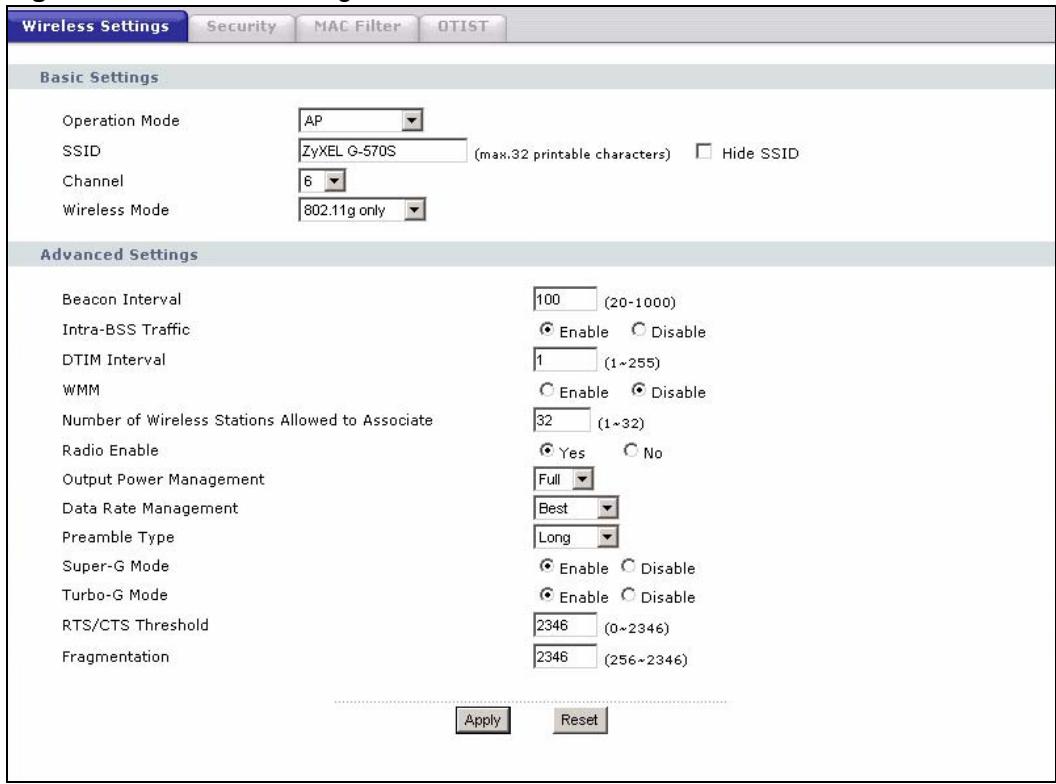
Figure 27 Wireless Settings: Access Point
The following table describes the labels in this screen.
Table 14 Wireless Settings: Access Point
| LABEL | DESCRIPTION |
| Basic Settings | |
| Operation Mode | Select the operating mode from the drop-down list. The options are Access Point, Wireless Client, Bridge and AP+Repeater. |
| SSID | Wireless stations associating to the access point (AP) must have the same SSID. Enter a descriptive name (up to 32 printable characters) for the wireless LAN. Spaces are allowed.Note: If you are configuring the device from a computer connected to the wireless LAN and you change the device's SSID, channel or security settings, you will lose your wireless connection when you press Apply to confirm. You must then change the wireless settings of your computer to match the device's new settings. |
| Hide SSID | Select this check box to hide the SSID in the outgoing beacon frame so a station cannot obtain the SSID through passive scanning using a site survey tool. |
| Channel | Set the operating frequency/channel depending on your particular region. Select a channel from the drop-down list box.Refer to the chapter on wizard setup for more information about channels. |
| Wireless Mode | Select 802.11b only to allow only IEEE 802.11b compliant WLAN devices to associate with the device.Select 802.11g only to allow only IEEE 802.11g compliant WLAN devices to associate with the device.Select Auto (11g/11b) to allow either IEEE 802.11b or IEEE 802.11g compliant WLAN devices to associate with the device. The transmission rate of your device might be reduced. |
| Advanced Settings | |
| Beacon Interval | Set the number of milliseconds that should pass between the sending out of beacons. |
| Intra-BSS Traffic | Intra-BSS traffic is traffic between wireless stations in the same BSS Enable Intra-BSS traffic to allow wireless stations connected to the device to communicate with each otherDISABLE Intra-BSS traffic to only allow wireless stations to communicate with the wired network, not with each other. |
| DTIM Interval | Set the interval for wireless clients in sleep mode to wake up and check for multicast or broadcast traffic.The AP includes a Delivery Traffic Indication Message (DTIM) in the beacon to notify wireless clients in sleep mode that there is a multicast or broadcast packet awaiting delivery. The interval is a multiple of the beacon interval. For example, if the beacon interval is 100 milliseconds and the DTIM interval is 2, the AP includes a DTIM with every second beacon (or every 200 milliseconds). |
| WMM | Select this to turn on WMM QoS (Wireless MultiMedia Quality of Service). The ZyXEL Device assigns priority to packets based on the 802.1q or DSCP information in their headers. If a packet has no WMM information in its header, it is assigned the default priority. |
| Number of Wireless Stations Allowed to Associate: | Use this field to set a maximum number of wireless stations that may connect to the device.Enter the number (from 1 to 32) of wireless stations allowed. |
| Radio Enable | Turn on the wireless adapter to allow wireless communications between the device and other IEEE 802.11b and IEEE 802.11g compliant wireless devices.Turn off the wireless adapter to stop wireless communications between the device and other IEEE 802.11b and IEEE 802.11g compliant wireless devices. |
| Output Power Management | Set the output power of the device in this field. If there is a high density of APs within an area, decrease the output power of the device to reduce interference with other APs.The options are Full, 50%, 25%, 12% and Min. |
| Data Rate Management | Use this field to select a maximum data rate for the wireless connection(s). Please note that this is a total rate to be shared by all of the device's wireless connections. |
| Preamble Type | Preamble is used to signal that data is coming to the receiver.Short preamble increases performance as less time sending preamble means more time for sending data. All IEEE 802.11b compliant wireless adapters support long preamble, but not all support short preamble.Select Long preamble if you are unsure what preamble mode the wireless adapters support, and to provide more reliable communications in busy wireless networks.Select Dynamic to have the device automatically use short preamble when all wireless clients support it, otherwise the device uses long preamble.Note: The device and the wireless stations MUST use the same preamble mode in order to communicate. |
| Super-G Mode | Super-G mode provides higher speed transmissions than regular IEEE 802.11g. The other device must also support super-G mode in order for the device to use it for the wireless connection. This is available when you select a Wireless Mode that includes IEEE 802.11g. |
| Turbo-G Mode | Turbo-G mode provides higher speed transmissions than regular IEEE 802.11g or super-G mode. The other device must also support turbo-G mode in order for the device to use it for the wireless connection. This is available when you select a Wireless Mode that includes IEEE 802.11g.Turbo-G uses two channels bonded together in order to achieve its higher transmission rates. This may cause interference with other APs in the area. The Channel field is automatically fixed at 6 when you use turbo-G mode. |
| RTS/CTS Threshold | Enter a value between 0 and 2346. The default is 2346. |
| Fragmentation | Enter a value between 256 and 2346. The default is 2346. It is the maximum data fragment size that can be sent. |
| Apply | Click Apply to save your changes back to the device. |
| Reset | Click Reset to begin configuring this screen afresh. |
7.6.2 Wireless Client Mode
Select Wireless Client in the Operation Mode field to display the screen as shown next. This mode has the device act as wireless client to connect to a wireless network.

WPA, WPA2 and IEEE 802.1x wireless security are not available when you use Wireless Client, Bridge or AP+Repeater mode.
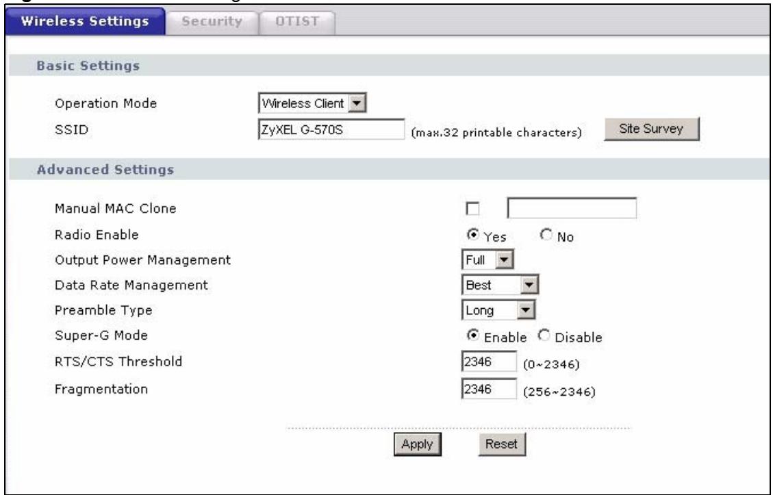
Figure 28 Wireless Settings: Wireless Client
The following table describes the labels in this screen.
Table 15 Wireless Settings: Wireless Client
| LABEL | DESCRIPTION |
| Basic Settings | |
| Operation Mode | Select the operating mode from the drop-down list. The options are Access Point, Wireless Client, Bridge and AP+Repeater. |
| SSID | Wireless stations associating to the access point (AP) must have the same SSID. Enter a descriptive name (up to 32 printable characters) for the wireless LAN. Spaces are allowed.Note: If you are configuring the device from a computer connected to the wireless LAN and you change the device's SSID, channel or security settings, you will lose your wireless connection when you click Apply to save your settings. You must then change the wireless settings of your computer to match the device's new settings. |
| Site Survey | Click this button to see details of access points (APs) within range. |
| Advanced Settings | |
| Manual MAC Cloning | Every Ethernet-capable device is issued with a unique Media Access Control (MAC) address at the factory. This address is used to identify the device across a network. Your ZyXEL Device is capable of “cloning”, or emulating, the MAC addresses of one or more other devices.Select the check box and enter the MAC address you want to clone. |
| Radio Enable | Turn on the wireless adapter to allow wireless communications between the device and other IEEE 802.11b and IEEE 802.11g compliant wireless devices.Turn off the wireless adapter to stop wireless communications between the device and other IEEE 802.11b and IEEE 802.11g compliant wireless devices. |
| Output Power Management | Set the output power of the device in this field. If there is a high density of APs within an area, decrease the output power of the device to reduce interference with other APs.The options are Full, 50%, 25%, 12% and Min. |
| Data Rate Management | Use this field to select a maximum data rate for the wireless connection(s). Please note that this is a total rate to be shared by all of the device's wireless connections. |
| Preamble Type | Preamble is used to signal that data is coming to the receiver.Short preamble increases performance as less time sending preamble means more time for sending data. All IEEE 802.11b compliant wireless adapters support long preamble, but not all support short preamble.Select Long preamble if you are unsure what preamble mode the wireless adapters support, and to provide more reliable communications in busy wireless networks.Select Dynamic to have the device automatically use short preamble when all wireless clients support it, otherwise the device uses long preamble.Note: The device and the wireless stations MUST use the same preamble mode in order to communicate. |
| Super-G Mode | Super-G mode provides higher speed transmissions than regular IEEE 802.11g. The other device must also support super-G mode in order for the device to use it for the wireless connection. This is available when you select a Wireless Mode that includes IEEE 802.11g.When Super-G Mode is enabled, the ZyXEL Device in wireless client mode can also connect to a turbo-G enabled wireless access point. |
| RTS/CTS Threshold | Enter a value between 0 and 2346. The default is 2346. |
| Fragmentation | Enter a value between 256 and 2346. The default is 2346. It is the maximum data fragment size that can be sent. |
| Apply | Click Apply to save your changes back to the device. |
| Reset | Click Reset to begin configuring this screen afresh. |
7.6.3 The Site Survey Window
Click on the Site Survey button in the Wireless > Wireless Settings screen (when the ZyXEL Device is in Wireless Client mode) to display the Site Survey screen. The ZyXEL Device searches for available access points (APs). Use this screen to view details of wireless access points within range.

Figure 29 Wireless Client Mode: the Site Survey Screen
The following table describes the labels in this screen.
Table 16 Wireless: the AP Survey Screen
| LABEL | DESCRIPTION |
| Site Survey | |
| SSID | This field displays theSSID (Service Set Identifier) of each access point. |
| BSSID | This field displays the MAC address of each access point. |
| Channel | This field displays the channel number used by each access point. |
| Wireless Mode | This field displays the wireless networking standard the access point is using. |
| Security | This field displays details of the access point's security and data encryption settings. |
| Signal Strength | This field displays the signal strength of each access point. |
| Rescan | Click Rescan to have the ZyXEL Device search again for available access points. |
7.6.4 Bridge Mode
The device can act as a wireless network bridge and establish wireless links with other APs. You need to know the MAC address of the peer device, which also must be in bridge mode.
When two devices connect in Bridge mode, they form a WDS (Wireless Distribution System) allowing the computers in one LAN to connect to the computers in another LAN. See the following example.

WPA, WPA2 and IEEE 802.1x wireless security are not available when you use Wireless Client, Bridge or AP+Repeater mode.

You can use only WEP or WPA2-PSK keys to encrypt traffic between APs.
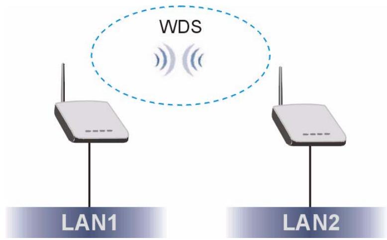
Figure 30 Bridging Example
Be careful to avoid bridge loops when you enable bridging in the ZyXEL Device. Bridge loops cause broadcast traffic to circle the network endlessly, resulting in possible throughput degradation and disruption of communications. The following examples show two network topologies that can lead to this problem:
If two or more ZyXEL Devices (in bridge mode) are connected to the same hub as shown next.
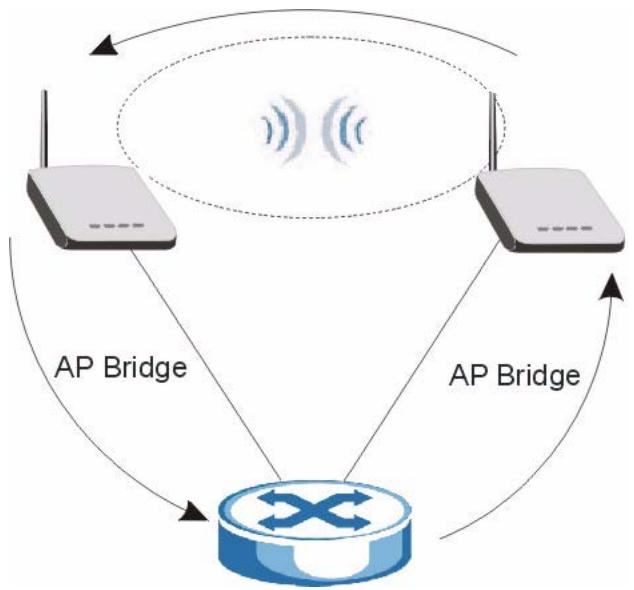
Figure 31 Bridge Loop: Two Bridges Connected to Hub
If your ZyXEL Device (in bridge mode) is connected to a wired LAN while communicating with another wireless bridge that is also connected to the same wired LAN as shown next.
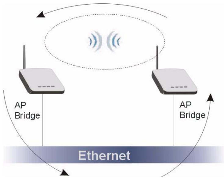
Figure 32 Bridge Loop: Bridge Connected to Wired LAN
To prevent bridge loops, ensure that your ZyXEL Device is not set to bridge mode while connected to both wired and wireless segments of the same LAN.
Select Bridge as the Operation Mode to have the device act as a wireless bridge only.
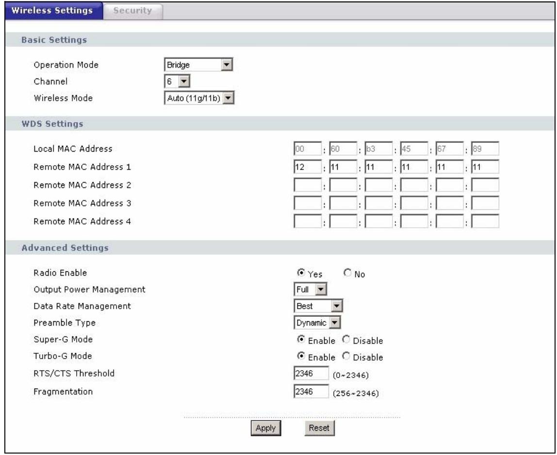
Figure 33 Wireless Settings: Bridge
The following table describes the labels in this screen.
Table 17 Wireless Settings: Bridge
| LABEL | DESCRIPTION |
| Basic Settings | |
| Operation Mode | Select the operating mode from the drop-down list. The options are Access Point, Wireless Client, Bridge and AP+Repeater.Note: If you are configuring the device from a computer connected to the wireless LAN and you change the device to use bridge mode, you will lose your wireless connection when you click Apply to save your settings. You must then connect to the device through the wired network. |
| Channel | Set the operating frequency/channel depending on your particular region. Select a channel from the drop-down list box.Refer to the chapter on wizard setup for more information about channels. |
| Wireless Mode | Select 802.11b only to allow only IEEE 802.11b compliant WLAN devices to associate with the device.Select 802.11g only to allow only IEEE 802.11g compliant WLAN devices to associate with the device.Select Auto (11g/11b) to allow either IEEE 802.11b or IEEE 802.11g compliant WLAN devices to associate with the device. The transmission rate of your device might be reduced. |
| WDS Settings | |
| Local MAC Address | This is the MAC address of the device. |
| Remote MAC Address 1~4 | Type the MAC address of the peer device(s) (the other access point(s) in your network) in a valid MAC address format, that is, six hexadecimal character pairs, for example, 12:34:56:78:9a:bc. |
| Advanced Settings | |
| Radio Enable | Turn on the wireless adapter to allow wireless communications between the device and other IEEE 802.11b and IEEE 802.11g compliant wireless devices.Turn off the wireless adapter to stop wireless communications between the device and other IEEE 802.11b and IEEE 802.11g compliant wireless devices. |
| Output Power Management | Set the output power of the device in this field. If there is a high density of APs within an area, decrease the output power of the device to reduce interference with other APs.The options are Full, 50%, 25%, 12% and Min. |
| Data Rate Management | Use this field to select a maximum data rate for the wireless connection(s). Please note that this is a total rate to be shared by all of the device's wireless connections. |
| Preamble Type | Preamble is used to signal that data is coming to the receiver. Short preamble increases performance as less time sending preamble means more time for sending data. All IEEE 802.11b compliant wireless adapters support long preamble, but not all support short preamble. Select Long preamble if you are unsure what preamble mode the wireless adapters support, and to provide more reliable communications in busy wireless networks. Select Dynamic to have the device automatically use short preamble when all wireless clients support it, otherwise the device uses long preamble. Note: The device and the wireless stations MUST use the same preamble mode in order to communicate. |
| Super-G Mode | Super-G mode provides higher speed transmissions than regular IEEE 802.11g. The other device must also support super-G mode in order for the device to use it for the wireless connection. This is available when you select a Wireless Mode that includes IEEE 802.11g. |
| Turbo-G Mode | Turbo-G mode provides higher speed transmissions than regular IEEE 802.11g or super-G mode. The other device must also support turbo-G mode in order to use it for the wireless connection. This is available when you select a Wireless Mode that includes IEEE 802.11g. Turbo-G uses two channels bonded together in order to achieve its higher transmission rates. This may cause interference with other APs in the area. The Channel field is automatically fixed at 6 when you use turbo-G mode. |
| RTS/CTS Threshold | Enter a value between 0 and 2346. The default is 2346. |
| Fragmentation | Enter a value between 256 and 2346. The default is 2346. It is the maximum data fragment size that can be sent. |
| Apply | Click Apply to save your changes back to the device. |
| Reset | Click Reset to begin configuring this screen afresh. |
7.6.5 AP+Repeater Mode
Select AP+Repeater as the Operation Mode to have the device act as an access point and a wireless bridge.
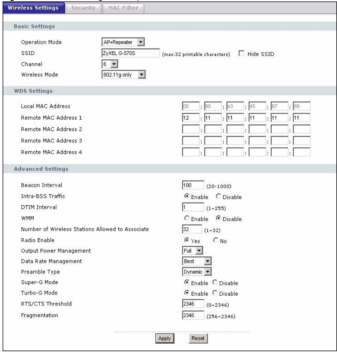
Figure 34 Wireless Settings: AP+Repeater
The following table describes the labels in this screen.
Table 18 Wireless Settings: AP + Repeater
| LABEL | DESCRIPTION |
| Basic Settings | |
| Operation Mode | Select the operating mode from the drop-down list. The options are Access Point, Wireless Client, Bridge and AP+Repeater. |
| SSID | Wireless stations associating to the access point (AP) must have the same SSID. Enter a descriptive name (up to 32 printable characters) for the wireless LAN. Spaces are allowed.Note: If you are configuring the device from a computer connected to the wireless LAN and you change the device's SSID, channel or security settings, you will lose your wireless connection when you click Apply to save your settings. You must then change the wireless settings of your computer to match the device's new settings. |
| Hide SSID | Select this check box to hide the SSID in the outgoing beacon frame so a station cannot obtain the SSID through passive scanning using a site survey tool. |
| Channel | Set the operating frequency/channel depending on your particular region. Select a channel from the drop-down list box.Refer to the chapter on wizard setup for more information about channels. |
| Wireless Mode | Select 802.11b only to allow only IEEE 802.11b compliant WLAN devices to associate with the device.Select 802.11g only to allow only IEEE 802.11g compliant WLAN devices to associate with the device.Select Auto (11g/11b) to allow either IEEE 802.11b or IEEE 802.11g compliant WLAN devices to associate with the device. The transmission rate of your device might be reduced. |
| WDS Settings | |
| Local MAC Address | This is the MAC address of the device. |
| Remote MAC Address 1~4 | Type the MAC address of the peer device in a valid MAC address format, that is,six hexadecimal character pairs, for example, 12:34:56:78:9a:bc. |
| Advanced Settings | |
| Beacon Interval | Set the number of milliseconds that should pass between the sending out of beacons. |
| Intra-BSS Traffic | Intra-BSS traffic is traffic between wireless stations in the same BSS.Enable Intra-BSS traffic to allow wireless stations connected to the device to communicate with each other.Disable Intra-BSS traffic to only allow wireless stations to communicate with the wired network, not with each other. |
| DTIM Interval | Set the interval for wireless clients in sleep mode to wake up and check for multicast or broadcast traffic.The AP includes a Delivery Traffic Indication Message (DTIM) in the beacon to notify wireless clients in sleep mode that there is a multicast or broadcast packet awaiting delivery. The interval is a multiple of the beacon interval. For example, if the beacon interval is 100 milliseconds and the DTIM interval is 2, the AP includes a DTIM with every second beacon (or every 200 milliseconds). |
| WMM | Select this to turn on WMM QoS (Wireless MultiMedia Quality of Service). The ZyXEL Device assigns priority to packets based on the 802.1q or DSCP information in their headers. If a packet has no WMM information in its header, it is assigned the default priority. |
| Number of Wireless Stations Allowed to Associate: | Use this field to set a maximum number of wireless stations that may connect to the device. Enter the number (from 1 to 32) of wireless stations allowed. |
| Radio Enable | Turn on the wireless adapter to allow wireless communications between the device and other IEEE 802.11b and IEEE 802.11g compliant wireless devices. Turn off the wireless adapter to stop wireless communications between the device and other IEEE 802.11b and IEEE 802.11g compliant wireless devices. |
| Output Power Management | Set the output power of the device in this field. If there is a high density of APs within an area, decrease the device's output power to reduce interference with other APs. The options are Full, 50%, 25%, 12% and Min. |
| Data Rate Management | Use this field to select a maximum data rate for the wireless connection(s). Please note that this is a total rate to be shared by all of the device's wireless connections. |
| Preamble Type | Preamble is used to signal that data is coming to the receiver. Short preamble increases performance as less time sending preamble means more time for sending data. All IEEE 802.11b compliant wireless adapters support long preamble, but not all support short preamble. Select Long preamble if you are unsure what preamble mode the wireless adapters support, and to provide more reliable communications in busy wireless networks. Select Dynamic to have the device automatically use short preamble when all wireless clients support it, otherwise the device uses long preamble. Note: The device and the wireless stations MUST use the same preamble mode in order to communicate. |
| Super-G Mode | Super-G mode provides higher speed transmissions than regular IEEE 802.11g. The other device must also support super-G mode in order to use it for the wireless connection. This is available when you select a Wireless Mode that includes IEEE 802.11g. |
| Turbo-G Mode | Turbo-G mode provides higher speed transmissions than regular IEEE 802.11g or super-G mode. The other device must also support turbo-G mode in order to use it for the wireless connection. This is available when you select a Wireless Mode that includes IEEE 802.11g. Turbo-G uses two channels bonded together in order to achieve its higher transmission rates. This may cause interference with other APs in the area. The Channel field is automatically fixed at 6 when you use turbo-G mode. |
| RTS/CTS Threshold | Enter a value between 0 and 2436. The default is 2436. |
| Fragmentation | Enter a value between 256 and 2436. The default is 2436. It is the maximum data fragment size that can be sent. |
| Apply | Click Apply to save your changes back to the device. |
| Reset | Click Reset to begin configuring this screen afresh. |
7.7 Configuring Wireless Security
Click Wireless > Security to display the Security screen. This screen varies according to the encryption method you select.

The encryption methods available depend on the Operation Mode you select in the Wireless > Wireless screen.
7.7.1 Wireless Security: Disable
If you do not enable any wireless security on your device, your network is accessible to any wireless networking device that is within range.
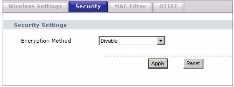
Figure 35 Wireless Security: Disable
The following table describes the labels in this screen.
Table 19 Wireless Security: Disable
| LABEL | DESCRIPTION |
| Encryption Method | Select Disable to have no wireless LAN security configured. |
| Apply | Click Apply to save your changes back to the device. |
| Reset | Click Reset to begin configuring this screen afresh. |
7.7.2 Wireless Security: WEP
WEP provides a mechanism for encrypting data using encryption keys. Both the AP and the wireless stations must use the same WEP key to encrypt and decrypt data. You can configure up to four 64-bit, 128-bit or 152-bit WEP keys, but only one key can be used at any one time.
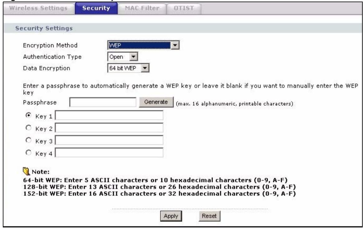
Figure 36 Wireless Security: WEP
The following table describes the labels in this screen.
Table 20 Wireless Security: WEP
| LABEL | DESCRIPTION |
| Encryption Method | Select WEP if you want to configure WEP encryption parameters. |
| Authentication Type | Select Auto, Open or Shared from the drop-down list box. |
| WEP Encryption | Select 64 bit WEP, 128 bit WEP or 152 bit WEP to enable data encryption. |
| Passphrase | If you selected 64-bit or 128-bit WEP, you can enter a “passphrase” (password phrase) of up to 32 case-sensitive printable characters and click Generate to have the device create four different WEP keys. |
| Generate | After you enter the passphrase, click Generate to have the device generates four different WEP keys automatically. |
| Key 1 to Key 4 | If you want to manually set the WEP keys, enter the WEP key in the field provided. Select a WEP key to use for data encryption. The WEP keys are used to encrypt data. Both the device and the wireless stations must use the same WEP key for data transmission. If you chose 64 bit WEP, then enter any 5 ASCII characters or 10 hexadecimal characters ("0-9", "A-F"). If you chose 128 bit WEP, then enter 13 ASCII characters or 26 hexadecimal characters ("0-9", "A-F"). If you chose 152 bit WEP, then enter 16 ASCII characters or 32 hexadecimal characters ("0-9", "A-F"). |
| Apply | Click Apply to save your changes back to the device. |
| Reset | Click Reset to begin configuring this screen afresh. |
7.7.3 Wireless Security: WPA(2)-PSK
Select WPA-PSK, WPA2-PSK or WPA-PSK & WPA2-PSK in the Encryption Method drop down list-box to display the screen displays as next.
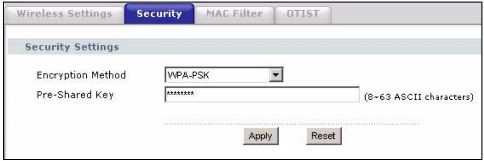
Figure 37 Wireless Security: WPA(2)-PSK
The following table describes the labels in this screen.
Table 21 Wireless Security: WPA-PSK
| LABEL | DESCRIPTION |
| Encryption Method | Select WPA-PSK, WPA2-PSK or WPA-PSK & WPA2-PSK if you want to configure a pre-shared key. Choose this option only if your wireless clients support it. |
| Pre-Shared Key | The encryption mechanisms used for WPA and WPA-PSK are the same. The only difference between the two is that WPA-PSK uses a simple common password, instead of user-specific credentials.Type a pre-shared key from 8 to 63 ASCII characters (including spaces and symbols). This field is case-sensitive. |
| Apply | Click Apply to save your changes back to the device. |
| Reset | Click Reset to begin configuring this screen afresh. |
7.7.4 Wireless Security: WPA(2)
WPA (Wi-Fi Protected Access) is a subset of the IEEE 802.11i standard. WPA2 (IEEE 802.11i) is a wireless security standard that defines stronger encryption, authentication and key management than WPA. Key differences between WPA(2) and WEP are user authentication and improved data encryption.
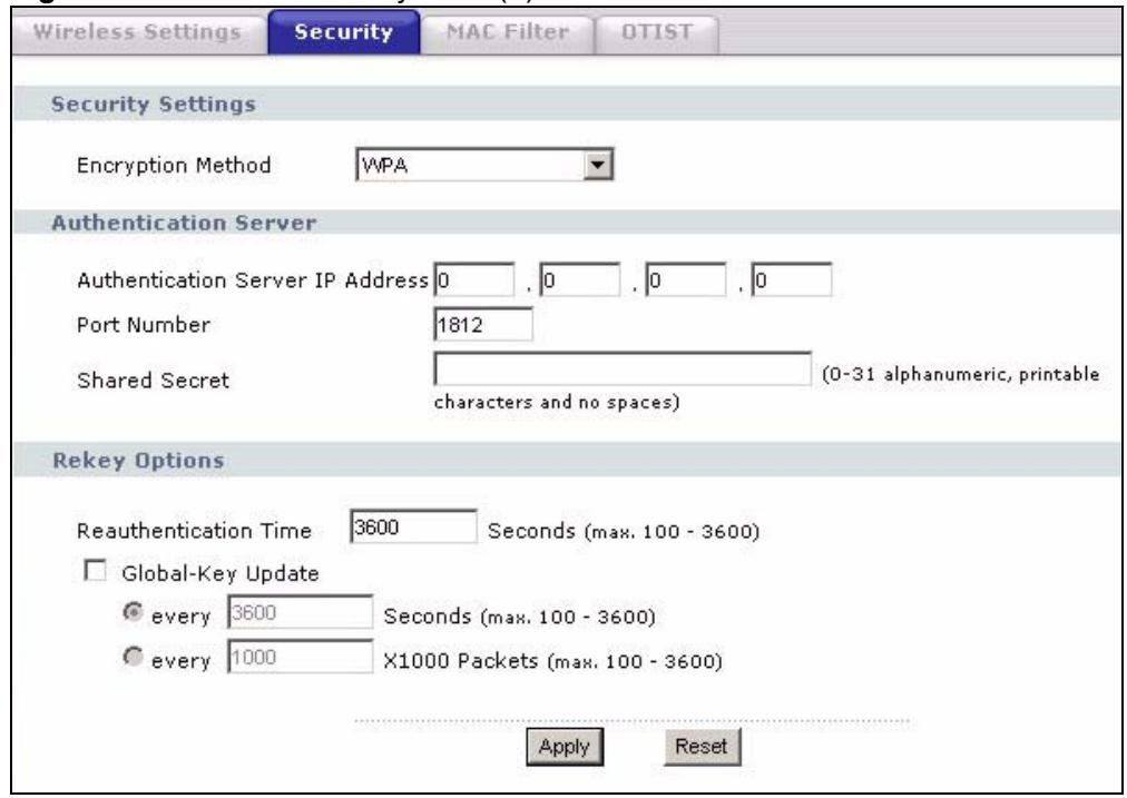
Figure 38 Wireless Security: WPA(2)
The following table describes the labels in this screen.
Table 22 Wireless Security: WPA(2)
| LABEL | DESCRIPTION |
| Encryption Method | Select WPA, WPA2 or WPA & WPA2 to configure user authentication and improved data encryption. |
| Note: WPA, WPA2 and IEEE 802.1x wireless security are not available when you use Wireless Client, Bridge or AP+Repeater mode. | |
| Note: You can only use WEP keys to encrypt traffic between APs. | |
| Authentication Server IP Address | Enter the IP address of the external authentication server in dotted decimal notation. |
| Port Number | Enter the port number of the external authentication server. The default port number is 1812.You need not change this value unless your network administrator instructs you to do so with additional information. |
| Shared Secret | Enter a password (up to 63 printable characters) as the key to be shared between the external authentication server and the device.The key must be the same on the external authentication server and your device.The key is not sent over the network. |
| Reauthentication Time | Specify how often wireless stations have to resend user names and passwords in order to stay connected. Enter a time interval between 100 and 3600 seconds.If wireless station authentication is done using a RADIUS server, the reauthentication timer on the RADIUS server has priority. |
| Global-Key Update | This is how often the AP sends a new group key out to all clients. The re-keying process is the WPA equivalent of automatically changing the WEP key for an AP and all stations in a WLAN on a periodic basis.Specify an interval either in seconds or thousands of packets that the device sends. |
| Apply | Click Apply to save your changes back to the device. |
| Reset | Click Reset to begin configuring this screen afresh. |
7.7.5 Wireless Security: IEEE 802.1x
The IEEE 802.1x standard outlines enhanced security methods for both the authentication of wireless stations and encryption key management.

Once you enable user authentication, you need to specify an external RADIUS server on the device for authentication.
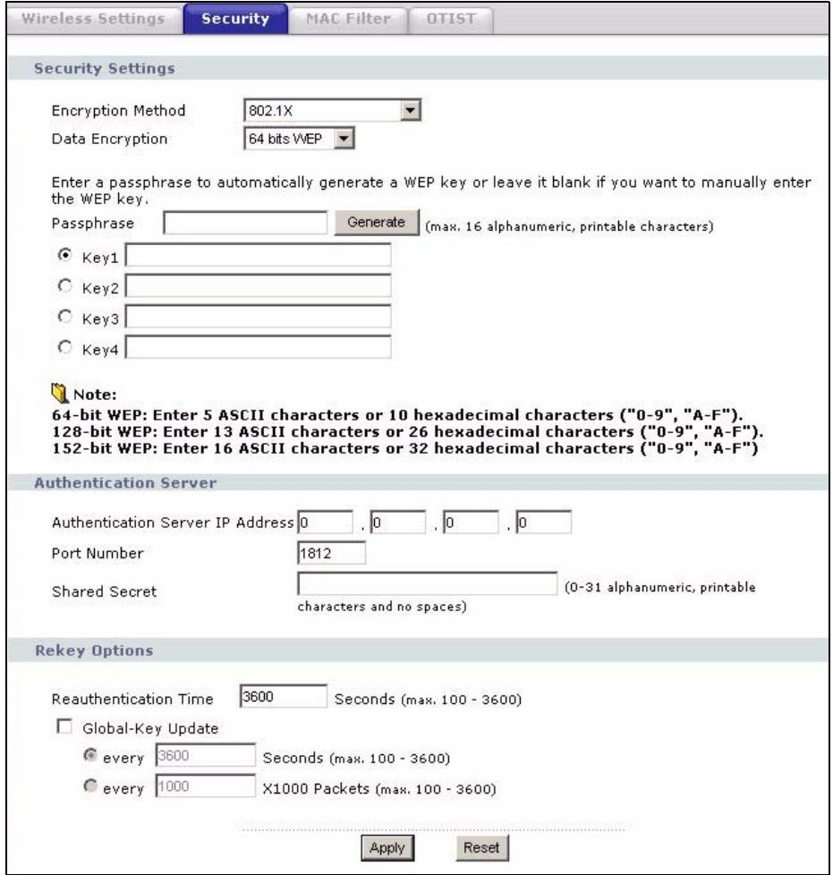
Figure 39 Wireless Security: 802.1x
The following table describes the labels in this screen.
Table 23 Wireless Security: 802.1x
| LABEL | DESCRIPTION |
| Encryption Method | Select 802.1X to configure authentication of wireless stations and encryption key management.Note: WPA, WPA2 and IEEE 802.1x wireless security are not available when you use Bridge or AP+Repeater mode. You can only use WEP keys to encrypt traffic between APs. |
| Data Encryption | Select None to allow wireless stations to communicate with the access points without using dynamic WEP key exchange.Select 64 bits WEP, 128 bits WEP or 152 bits WEP to enable data encryption.Up to 32 stations can access the device when you configure dynamic WEP key exchange. |
| Authentication Server IP Address | Enter the IP address of the external authentication server in dotted decimal notation. |
| Port Number | Enter the port number of the external authentication server. The default port number is 1812.You need not change this value unless your network administrator instructs you to do so with additional information. |
| Shared Secret | Enter a password (up to 63 printable characters) as the key to be shared between the external authentication server and the device.The key must be the same on the external authentication server and your device.The key is not sent over the network. |
| Reauthentication Time | Specify how often wireless stations have to resend user names and passwords in order to stay connected. Enter a time interval between 100 and 3600 seconds.If wireless station authentication is done using a RADIUS server, the reauthentication timer on the RADIUS server has priority. |
| Global-Key Update | This is how often the AP sends a new group key out to all clients. The re-keying process is the WPA equivalent of automatically changing the WEP key for an AP and all stations in a WLAN on a periodic basis.Specify an interval either in seconds or thousands of packets that the device sends. |
| Apply | Click Apply to save your changes back to the device. |
| Reset | Click Reset to begin configuring this screen afresh. |
7.8 MAC Filter
The MAC filter screen allows you to give exclusive access to up to 32 devices (Allow Association) or exclude up to 32 devices from accessing the device (Deny Association). Every Ethernet device has a unique MAC (Media Access Control) address. The MAC address is assigned at the factory and consists of six pairs of hexadecimal characters, for example, 00:A0:C5:00:00:02. You need to know the MAC addresses of the devices to configure this screen.
The MAC filter works when the device functions as an AP. It allows or denies wireless client access. The MAC filter does not apply to bridge or repeater functions.
The following applies if you set the device to client mode and want to connect to an AP that uses a MAC filter. After the device turns on in client mode, it clones the MAC address of the first packets that it receives from devices connected to the Ethernet port. It uses this MAC address on the packets that it sends to an AP. All of the packets that the device sends to an AP will appear to be from the first device that connected to the Ethernet port. If you turn the device off and back on, it again clones the MAC address of the first packets that it receives from devices connected to the Ethernet port. You may be able to check the association list on the AP to determine which MAC address the device is currently using.
To change your device's MAC filter settings, click Wireless > MAC Filter. The screen appears as shown.

Be careful not to list your computer's MAC address and select Deny the following MAC address to associate when managing the device via a wireless connection. This would lock you out.
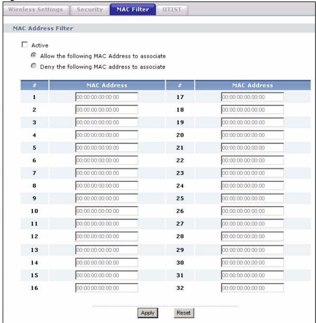
Figure 40 MAC Filter
The following table describes the labels in this screen.
Table 24 MAC Filter
| LABEL | DESCRIPTION |
| Active | Select the check box to enable MAC address filtering and define the filter action for the list of MAC addresses in the MAC address filter table. Select Allow the following MAC address to associate to permit access to the device. MAC addresses not listed will be denied access to the device. Select Deny the following MAC address to associate to block access to the device. MAC addresses not listed will be allowed to access the device. |
| # | This is the index number of the MAC address. |
| MAC Address | Enter the MAC addresses (in XX:XX:XX:XX:XX format) of the wireless station that are allowed or denied access to the device in these address fields. |
| Apply | Click Apply to save your changes back to the device. |
| Reset | Click Reset to begin configuring this screen afresh. |
7.9 OTIST
In a wireless network, the wireless clients must have the same SSID and security settings as the access point (AP) or wireless router (we will refer to both as "AP" here) in order to associate with it. Traditionally this meant that you had to configure the settings on the AP and then manually configure the exact same settings on each wireless client.
OTIST (One-Touch Intelligent Security Technology) allows you to transfer your AP's SSID and WEP or WPA-PSK security settings to wireless clients that support OTIST and are within transmission range. You can also choose to have OTIST generate a WPA-PSK key for you if you didn't configure one manually.

OTIST replaces the pre-configured wireless settings on the wireless clients.

OTIST is not available in AP+Repeater or Bridge mode at the time of writing.
7.9.1 Enabling OTIST
You must enable OTIST on both the AP and wireless client before you start transferring settings.

The AP and wireless client(s) MUST use the same Setup key.
7.9.1.1 ZyXEL Device in AP Mode
You can enable OTIST using the OTIST button or the web configurator.
7.9.1.1.1 OTIST Button
If you use the OTIST button, the default (01234567) or previous saved (through the web configurator) Setup key is used to encrypt the settings that you want to transfer.
Hold in the OTIST button for one or two seconds.
7.9.1.1.2 Web Configurator
Click Wireless > OTIST in AP, AP+Repeater or Bridge mode to configure and enable OTIST. The screen appears as shown.
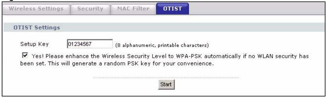
Figure 41 OTIST
The following table describes the labels in this screen.
Table 25 OTIST
| LABEL | DESCRIPTION |
| One-Touch Intelligent Security Technology | |
| Setup Key | Enter the setup key of up to eight printable characters. The default OTIST setup key is "01234567".Note: If you change the OTIST setup key here, you must also make the same change on the wireless client(s). |
| Yes! | To have OTIST automatically generate a WPA-PSK key, select this check box. If you manually configured a WEP key or a WPA-PSK key and you also select this check box, then the key you manually configured is used. |
| Start | Click Start to encrypt the wireless security data using the setup key and have the device set the wireless client to use the same wireless settings as the device. You must also activate and start OTIST on the wireless client at the same time. The process takes three minutes to complete. |
7.9.1.2 Wireless Client
Start the ZyXEL utility and click the Adapter tab. Select the OTIST check box, enter the same Setup Key as your AP's and click Save.
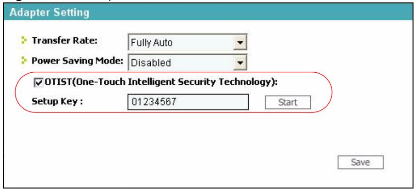
Figure 42 Example Wireless Client OTIST Screen
7.9.1.3 ZyXEL Device in Wireless Client Mode
If you are using the ZyXEL Device in Wireless Client mode, you can enable OTIST using either the OTIST button or the web configurator.
7.9.1.3.1 Wireless Client Mode: OTIST Button
If you use the OTIST button, the default (01234567) or previous saved (through the web configurator) Setup key is used.
Double-click the OTIST button to automatically change the ZyXEL Device to wireless client mode and start OTIST.
7.9.1.3.2 Wireless Client Mode: Web Configurator
Start the web configurator and click Wireless. Select Wireless Client in the Operation Mode field.
Click on the OTIST tab. The screen displays as shown. Enter the same Setup Key as your AP's. Click Start when you are ready to begin OTIST.
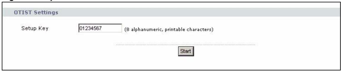
Figure 43 ZyXEL Device in Wireless Client Mode: OTIST Screen
7.9.2 Starting OTIST

You must click Start in the AP OTIST web configurator screen and in the wireless client(s) Adapter screen all within three minutes (at the time of writing). You can start OTIST in the wireless clients and AP in any order but they must all be within range and have OTIST enabled.
1 In the AP, a web configurator screen pops up showing you the security settings to transfer. After reviewing the settings, click OK.
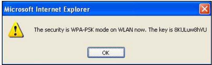
Figure 44 Security Key
2 This screen appears while OTIST settings are being transferred. It closes when the transfer is complete.
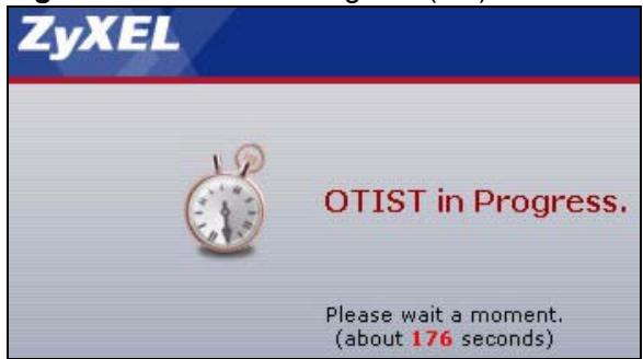
Figure 45 OTIST in Progress (AP)
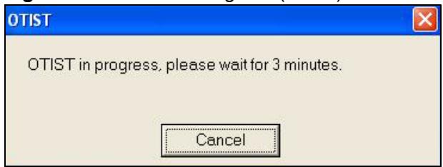
Figure 46 OTIST in Progress (Client)
- In the wireless client, you see this screen if it can't find an OTIST-enabled AP (with the same Setup key). Click OK to go back to the ZyXEL utility main screen.
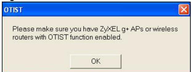
Figure 47 No AP with OTIST Found
- If there is more than one OTIST-enabled AP within range, you see a screen asking you to select one AP to get settings from.
7.9.3 Notes on OTIST
1 If you enabled OTIST in the wireless client, you see this screen each time you start the utility. Click Yes for it to search for an OTIST-enabled AP.
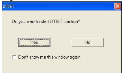
Figure 48 Start OTIST?
2 If an OTIST-enabled wireless client loses its wireless connection for more than ten seconds, it will search for an OTIST-enabled AP for up to one minute. (If you manually have the wireless client search for an OTIST-enabled AP, there is no timeout; click Cancel in the OTIST progress screen to stop the search.)
3 When the wireless client finds an OTIST-enabled AP, you must still click Start in the AP OTIST web configurator screen or hold in the OTIST button (for one or two seconds) for the AP to transfer settings.
4 If you change the SSID or the keys on the AP after using OTIST, you need to run OTIST again or enter them manually in the wireless client(s).
5 If you configure OTIST to generate a WPA-PSK key, this key changes each time you run OTIST. Therefore, if a new wireless client joins your wireless network, you need to run OTIST on the AP and ALL wireless clients again.
PART III
Management and
Troubleshooting
Management Screens (89)
Troubleshooting (95)
Management Screens
This chapter describes the Maintenance screens.
8.1 Maintenance Overview
Use these maintenance screens to change the password, view logs, back up or restore the ZyXEL Device's configuration and change the web configurator language.
8.2 Password
To change your device's password (recommended), click Management. The screen appears as shown. This screen allows you to change the device's password.
If you forget your password (or the device IP address), you will need to reset the device. See the section on resetting the device for details.
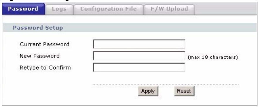
Figure 49 Management: Password
The following table describes the labels in this screen.
Table 26 Management: Password
| LABEL | DESCRIPTION |
| Current Password | Type in your existing system password (1234 is the default password). |
| New Password | Type your new system password (up to 30 printable characters). Spaces are not allowed. Note that as you type a password, the screen displays an asterisk (*) for each character you type. |
| Retype to Confirm | Retype your new system password for confirmation. |
| Apply | Click Apply to save your changes back to the device. |
| Cancel | Click Cancel to reload the previous configuration for this screen. |
8.3 Logs
Click Management > Logs to open the Logs screen.
You can view logs and alert messages in this screen. Once the log table is full, old logs are deleted as new logs are created.
Click a column heading to sort the entries. A triangle indicates the direction of the sort order.
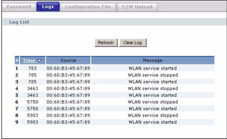
Figure 50 Management: Logs
The following table describes the labels in this screen.
Table 27 Management: Logs
| LABEL | DESCRIPTION |
| Display | Select a category of logs to view. |
| Refresh | Click Refresh to renew the log screen. |
| Clear Log | Click Clear Log to clear all the logs. |
| # | This is the log's index number. |
| Time | This field displays the time the log was recorded. It is the number of seconds since the last time the system turned on. |
| Message | This field states the reason for the log. |
| Source | This field lists the source IP address and the port number of the incoming packet that caused the log. |
| Destination | This field lists the destination IP address and the port number of the outgoing packet that caused the log. |
| Note | This field displays additional information about the log entry. |
8.4 Configuration File
The configuration file (often called the romfile or rom-0) contains the factory default settings such as password and TCP/IP Setup, etc. It arrives from ZyXEL with a .rom filename extension. Once you have customized the device's settings, they can be saved back to your computer under a filename of your choosing.
Click Management > Configuration File. Information related to factory defaults, backup configuration, and restoring configuration appears as shown next.
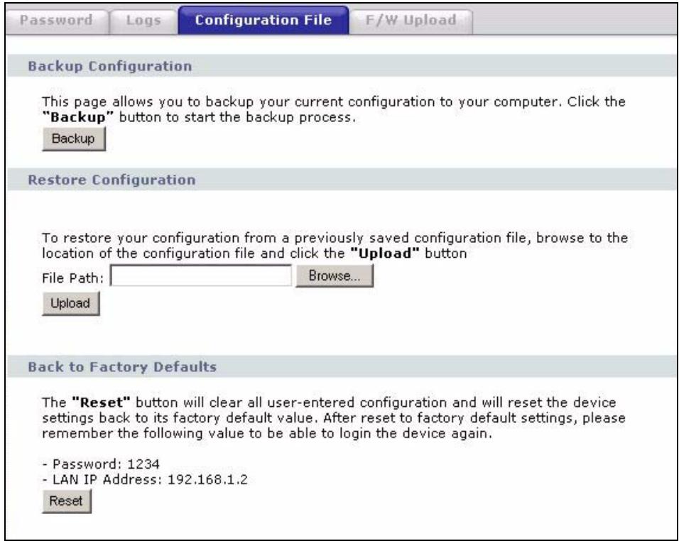
Figure 51 Management: Configuration File
8.4.1 Backup Configuration
Backup configuration allows you to back up (save) the device's current configuration to a file on your computer. Once your device is configured and functioning properly, it is highly recommended that you back up your configuration file before making configuration changes. The backup configuration file will be useful in case you need to return to your previous settings.
Click Backup to save the device's current configuration to your computer.
8.4.2 Restore Configuration
Restore configuration allows you to upload a new or previously saved configuration file from your computer to your device.
Table 28 Management: Configuration File:Restore Configuration
| LABEL | DESCRIPTION |
| File Path | Type in the location of the file you want to upload in this field or click Browse ... to find it. |
| Browse... | Click Browse... to find the file you want to upload. Remember that you must decompress compressed (.zip) files before you can upload them. |
| Upload | Click Upload to begin the upload process. |

Do not turn off the device while configuration file upload is in progress.
The following screen displays. You must wait one minute before logging into the device again.
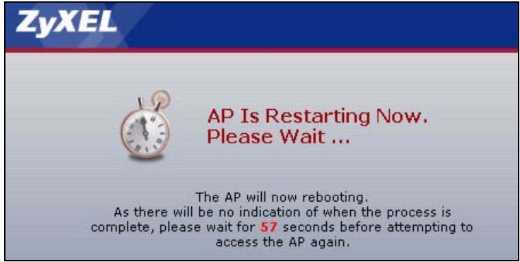
Figure 52 Configuration Upload Successful
The device automatically restarts in this time causing a temporary network disconnect. In some operating systems, you may see the following icon on your desktop.
Figure 53 Network Temporarily Disconnected
If you uploaded the default configuration file you may need to change the IP address of your computer to be in the same subnet as that of the default device IP address (192.168.1.2).
If the upload was not successful, the following screen will appear. Click Return to go back to the Configuration File screen.
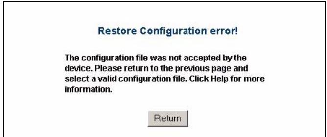
Figure 54 Configuration Upload Error
8.4.3 Back to Factory Defaults
Clicking the RESET button in this section clears all user-entered configuration information and returns the device to its factory defaults. The following warning screen will appear.
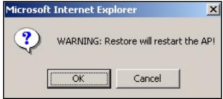
Figure 55 Reset Warning Message
You can also press the RESET button on the rear panel to reset the factory defaults of your device. Refer to the section on resetting the device for more information on the RESET button.
8.5 F/W Upload Screen
Find firmware at www.zyxel.com in a file that (usually) uses the system model name with a .rmt extension, for example, "zyxel.rmt". The upload process uses HTTP (Hypertext Transfer Protocol) and may take up to two minutes. After a successful upload, the system will reboot.
Click Management > F/W Upload to display the screen as shown. Follow the instructions in this screen to upload firmware to your device.
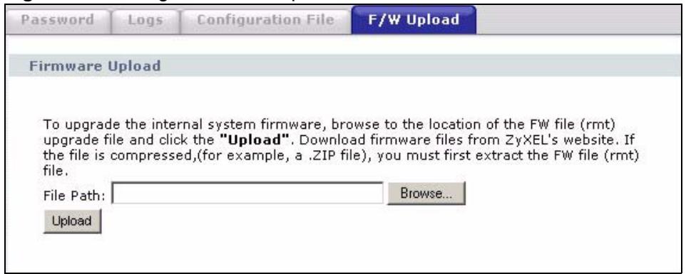
Figure 56 Management: F/W Upload
The following table describes the labels in this screen.
Table 29 Management: F/W Upload
| LABEL | DESCRIPTION |
| File Path | Type in the location of the file you want to upload in this field or click Browse ... to find it. |
| Browse... | Click Browse... to find the .rmt file you want to upload. Remember that you must decompress compressed (.zip) files before you can upload them. |
| Upload | Click Upload to begin the upload process. This process may take up to two minutes. |

Do not turn off the device while firmware upload is in progress!
The following screen appears. Wait two minutes before logging into the device again.
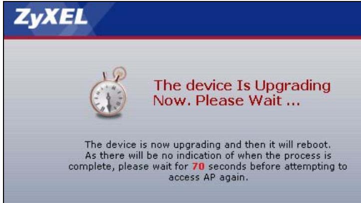
Figure 57 Firmware Upgrading Screen
The device automatically restarts in this time causing a temporary network disconnect. In some operating systems, you may see the following icon on your desktop.
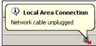
Figure 58 Network Temporarily Disconnected
After two minutes, log in again and check your new firmware version in the System Status screen.
If the upload was not successful, the following status message displays at the bottom of the screen.

Figure 59 Firmware Upload Error
Troubleshooting
This chapter offers some suggestions to solve problems you might encounter. The potential problems are divided into the following categories.
- Power, Hardware Connections, and LEDs
ZyXEL Device Access and Login - Internet Access
9.1 Power, Hardware Connections, and LEDs

The ZyXEL Device does not turn on. None of the LEDs turn on.
6 Make sure you are using the power adaptor or cord included with the ZyXEL Device.
7 Make sure the power adaptor or cord is connected to the ZyXEL Device and plugged in to an appropriate power source. Make sure the power source is turned on.
8 Disconnect and re-connect the power adaptor or cord to the ZyXEL Device.
9 If the problem continues, contact the vendor.

One of the LEDs does not behave as expected.
1 Make sure you understand the normal behavior of the LED. See Section 1.5 on page 27.
2 Check the hardware connections. See the Quick Start Guide.
3 Inspect your cables for damage. Contact the vendor to replace any damaged cables.
4 Disconnect and re-connect the power adaptor to the ZyXEL Device.
5 If the problem continues, contact the vendor.
9.2 ZyXEL Device Access and Login

I forgot the IP address for the ZyXEL Device.
1 The default IP address is 192.168.1.2.
2 If this does not work, you have to reset the device to its factory defaults. See Section 1.8 on page 29.

I forgot the password.
1 The default password is 1234.
2 If this does not work, you have to reset the device to its factory defaults. See Section 1.8 on page 29.

I cannot see or access the Login screen in the web configurator.
1 Make sure you are using the correct IP address.
- The default IP address is 192.168.1.2.
- If you changed the IP address (Section 6.2 on page 52), use the new IP address.
- If you changed the IP address and have forgotten it, see the troubleshooting suggestions for I forgot the IP address for the ZyXEL Device.
2 Check the hardware connections, and make sure the LEDs are behaving as expected. See the Quick Start Guide.
3 Make sure your Internet browser does not block pop-up windows and has JavaScript and Java enabled. See Appendix C on page 123.
4 Make sure your computer is in the same subnet as the ZyXEL Device. (If you know that there are routers between your computer and the ZyXEL Device, skip this step.)
- If there is no DHCP server on your network, make sure your computer's IP address is in the same subnet as the ZyXEL Device. See Appendix B on page 107.
5 Reset the device to its factory defaults, and try to access the ZyXEL Device with the default IP address. See Section 1.8 on page 29.
6 If the problem continues, contact the network administrator or vendor.

I can see the Login screen, but I cannot log in to the ZyXEL Device.
1 Make sure you have entered the user name and password correctly. The default password is 1234. This field is case-sensitive, so make sure [Caps Lock] is not on.
2 You cannot log in to the web configurator while someone is using Telnet to access the ZyXEL Device. Log out of the ZyXEL Device in the other session, or ask the person who is logged in to log out.
3 Disconnect and re-connect the power adaptor or cord to the ZyXEL Device.
4 If this does not work, you have to reset the device to its factory defaults. See Section 1.8 on page 29.

I cannot access the ZyXEL Device from the WLAN.
Make sure the wireless adapter on the wireless station is working properly.
Check that both the G-570S and your wireless station are using the same ESSID, channel and security settings.

I cannot ping any computer on the WLAN.
Make sure the wireless adapter on the wireless station(s) is working properly.
Check that both the G-570S and wireless station(s) are using the same ESSID, channel and security settings.

I cannot Telnet to the ZyXEL Device.
See the troubleshooting suggestions for I cannot see or access the Login screen in the web configurator. Ignore the suggestions about your browser.

I cannot use FTP to upload / download the configuration file. / I cannot use FTP to upload new firmware.
See the troubleshooting suggestions for I cannot see or access the Login screen in the web configurator. Ignore the suggestions about your browser.
9.3 Internet Access

I cannot access the Internet.
1 Check the hardware connections, and make sure the LEDs are behaving as expected. See the Quick Start Guide and Section 1.5 on page 27.
2 If you are trying to access the Internet wirelessly, make sure the wireless settings in the wireless client are the same as the settings in the AP.
3 Disconnect all the cables from your device, and follow the directions in the Quick Start Guide again.
4 If the problem continues, contact your ISP.

I cannot access the Internet anymore. I had access to the Internet (with the ZyXEL Device), but my Internet connection is not available anymore.
1 Check the hardware connections, and make sure the LEDs are behaving as expected. See the Quick Start Guide and Section 1.5 on page 27.
2 Disconnect and re-connect the power adaptor to the ZyXEL Device.
3 If the problem continues, contact your ISP.

The Internet connection is slow or intermittent.
1 There might be a lot of traffic on the network. Look at the LEDs, and check Section 1.5 on page 27. If the ZyXEL Device is sending or receiving a lot of information, try closing some programs that use the Internet, especially peer-to-peer applications.
2 Check the signal strength. If the signal strength is low, try moving the ZyXEL Device closer to the AP if possible, and look around to see if there are any devices that might be interfering with the wireless network (for example, microwaves, other wireless networks, and so on).
3 Disconnect and re-connect the power adaptor to the ZyXEL Device.
4 If the problem continues, contact the network administrator or vendor.
PART IV
Appendices and Index
Product Specifications (101)
Setting up Your Computer's IP Address (107)
Pop-up Windows, JavaScript and Java Permissions (123)
Wireless LANs (129)
Customer Support (143)
Legal Information (147)
Index (151)
Product Specifications
The following tables summarize the ZyXEL Device's hardware and firmware features.
Hardware Specifications
Table 30 Hardware Specifications
| Default IP Address | 192.168.1.2 |
| Default Subnet Mask | 255.255.255.0 (24 bits) |
| Default Password | 1234 |
| Dimensions | 112 mm (Wide) × 106 mm (Deep) × 28.5 mm (High) |
| Weight | 203 g |
| Ethernet Port | One auto-negotiating, auto MDI/MDI-X 10/100 Mbps RJ-45 Ethernet port |
| Antenna | 1 detachable dipole antenna |
| Power Requirements | 12VDC @ 1 Amp maximum |
| Operation Temperature | 0° C ~ 50°C |
| Storage Temperature | -30° ~ 60°C |
| Operation Humidity | 20% ~ 95% RH |
| Storage Humidity | 20% ~ 95% RH |
Feature Specifications
Table 31 Feature Specifications
| Protocol Support | Transparent bridging for unsupported network layer protocols DHCP Client DHCP relay |
| Standards Compliance | IEEE 802.3 and 802.3u 10Base-T and 100Base-TX physical layer specification IEEE 802.11g specification compliance for wireless LAN IEEE 802.11b specification compliance for wireless LAN IEEE 802.1x security standard support Wi-Fi certificate |
| Roaming | IEEE 802.11g compliant IEEE 802.11b compliant IEEE 802.11f partially compliant (without re-authentication) |
| Operating Modes | Access Point Client Bridge Access Point and Repeater |
| Wireless Links | The ZyXEL Device can act as a bridge, establishing wireless links with other APs or as a repeater, establishing wireless links to APs. Up to four bridge links. Two or more repeater links are supported. It is suggested that you only use up to three repeater links. |
| Management | Embedded Web Configurator Command-line interface Telnet support (Password-protected telnet access to internal configuration manager). FTP/Web for firmware downloading and configuration backup and restore. Limitation of client connections (# is configurable, default: unlimited) Intra BSS Block (enable/disable) Output Power Management (4-levels) |
| Security | WPA and IEEE 802.1x security (EAP-TLS, EAP-TTLS, LEAP., EAP-PEAP and Win XP PEAP included) 64/128/152-bits WEP WPA/WPA2 support based on 802.11i standard Dynamic WEP key exchange MAC address filtering through WLAN (supports up to 32 MAC address entries AES support |
| Diagnostics Capabilities | Built-in Diagnostic Tools for FLASH memory, RAM, Ethernet port and wireless port. Syslog Error log Trace Log Packet Log |
| Hardware Features | Restore Factory Defaults (reset) Button Status LEDs • PWR • ETHN • OTIST • WLAN |
| WDS Functionality | A Distribution System (DS) is a wired connection between two or more APs, while a Wireless Distribution System (WDS) is a wireless connection. Your G-570S supports WDS connections to other G-570S APs. This provides a cost-effective solution for wireless network expansion. |
| OTIST (One-Touch Intelligent Security Technology) | OTIST allows your ZyXEL Device to assign its SSID and security settings (WEP or WPA-PSK) to ZyXEL wireless adapters that support OTIST and are within transmission range. The ZyXEL wireless adapters must also have OTIST enabled. |
| 10/100M Auto-negotiating Ethernet/ Fast Ethernet Interface | This auto-negotiating feature allows the ZyXEL Device to detect the speed of incoming transmissions and adjust appropriately without manual intervention. It allows data transfer of either 10 Mbps or 100 Mbps in either half-duplex or full-duplex mode depending on your Ethernet network. Ethernet port connections can be in half-duplex or full-duplex mode. Full-duplex refers to a device's ability to send and receive simultaneously, while half-duplex indicates that traffic can flow in only one direction at a time. The Ethernet port must use the same speed or duplex mode setting as the peer Ethernet port in order to connect. |
| 10/100M Auto-crossover Ethernet/Fast Ethernet Interface | The LAN interface automatically adjusts to either a crossover or straight-through Ethernet cable. |
| Reset Button | The reset button is built into the rear panel. Use this button to restart the device or restore the factory default password. |
| 802.11g Wireless LAN Standard | The ZyXEL Device complies with the IEEE 802.11g wireless standard. IEEE 802.11g is fully compatible with the IEEE 802.11b standard. This means an IEEE 802.11b radio card can interface directly with an IEEE 802.11g access point (and vice versa) at 11 Mbps or lower depending on range. |
| Wi-Fi Protected Access | Wi-Fi Protected Access (WPA) is a subset of the IEEE 802.11i standard. Key differences between WPA and WEP are user authentication and improved data encryption. |
| WPA2 | WPA 2 (IEEE 802.11i) is a wireless security standard that defines stronger encryption, authentication and key management than WPA. |
| SSL Passthrough | The ZyXEL Device allows SSL connections to go through the ZyXEL Device. SSL (Secure Sockets Layer) uses a public key to encrypt data that's transmitted over an SSL connection. Both Netscape Navigator and Internet Explorer support SSL, and many Web sites use the protocol to obtain confidential user information, such as credit card numbers. By convention, URLs that require an SSL connection start with "https" instead of "http". |
| Wireless LAN MAC Address Filtering | Your ZyXEL Device checks the MAC address of the wireless station against a list of allowed or denied MAC addresses. |
| WEP Encryption | WEP (Wired Equivalent Privacy) encrypts data frames before transmitting over the wireless network to help keep network communications private. |
| IEEE 802.1x Network Security | The ZyXEL Device supports the IEEE 802.1x standard to enhance user authentication. Use an EAP-compatible RADIUS (RFC2138, 2139 - Remote Authentication Dial In User Service) server to authenticate a limitless number of users using EAP (Extensible Authentication Protocol). EAP is an authentication protocol that supports multiple types of authentication. |
| Full Network Management | The embedded web configurator is an all-platform web-based utility that allows you to easily access the ZyXEL Device's management settings. |
| Logging and Tracing | Built-in message logging and packet tracing. |
| Wireless Association List | With the wireless association list, you can see the list of the wireless stations that are currently using the ZyXEL Device to access your wired network. When the ZyXEL Device is in client mode, the wireless association list displays a list of wireless devices and networks in the area. |
| Output Power Management | Output Power Management is the ability to set the level of output power. There may be interference or difficulty with channel assignment when there is a high density of APs within a coverage area. In this case you can lower the output power of each access point, thus enabling you to place access points closer together. |
| Limit the Number of Client Connections | You may set a maximum number of wireless stations that may connect to the ZyXEL Device. This may be necessary if for example, there is interference or difficulty with channel assignment due to a high density of APs within a coverage area. |
Wireless Specifications
Table 32 Wireless Specifications
| Data Rate | Super G/11g: 108M/54M/48M/36M/24M/18M/12M/9/6 Mbps auto fallback11b: 11Mbps/5.5Mbps/2Mbps/1Mbps auto fallback |
| Communication Method | Half Duplex |
| Transmission/Emission Type | Direct Sequence Spread Spectrum (DSSS) |
| Security | Wired Equivalent Privacy (WEP) data encryptionDynamic WEP key exchangeWiFi Protected Access (WPA)IEEE 802.1x |
| RF frequency range | 2.412~2.462GHz: North America2.412MHz~2.484 GHz: Japan2.412-2.472 GHz: Europe ETSI |
| Data modulation type | OFDM/BPSK/QPSK/CCK/PBCC/DQPSK/DBPSK |
| Output PowerA | 11b : 18+/-2dBm @ 11/5.5/2/1Mbps.11g : 16+/-2dBm @ 54Mbps. |
| Sensitivity | 54M: -65dBm 11M: -80dBm |
| Coverage | Indoor: up to 100metersOutdoor: up to 400meters |
| Antenna | 1 external detachable 2dBi dipole antenna with R-SMA connector |
A. Peak Output Power is 11b: 17.32 dBm, 11g: 21.48 dBm, Turbo mode: 22.25 dBm
Approvals
Table 33 Approvals
| SAFETY | North America | ANSI/UL-1950 3rd CSA C22.2 No. 950 3rd |
| European Union (CE mark) | EN60950 (1992+A1+A2+A3+A4+A11) IEC 60950 3rd | |
| EMI | North America | FCC Part 15 Class B |
| European Union (CE mark) | EN55022 Class BEN61000-3-2EN61000-3-3 | |
| EMS | European Union (CE mark) | |
| ELECTROSTATIC DISCHARGE | EN61000-4-2 | |
| RADIO-FREQUENCY ELECTROMAGNETIC FIELD | EN61000-4-3 | |
| EFT/BURST | EN61000-4-4 | |
| SURGE | EN61000-4-5 | |
| CONDUCTED SUSCEPTIBILITY | EN61000-4-6 | |
| POWER MAGNETIC | EN61000-4-8 | |
| VOLTAGE DIPS/INTERRUPTION | EN61000-4-11 | |
| EM FIELD FROM DIGITAL TELEPHONES | ENV50204 | |
| LAN COMPATIBILITY | SmartBit | |
| FOR WIRELESS PC CARD | FCC Part15C, Sec15.247 | |
| ETS300 328ETS300 826 | ||
| CE mark |
Power Adaptor Specifications
Table 34 Power Adaptor Specifications
| AUSTRALIAN PLUG STANDARDS | |
| AC Power Adapter Model | AD-121AE |
| Input Power | 240 Volts AC 50Hz |
| Output Power | 12 Volts DC ±5% 1 Amp |
| Power Consumption | 12 Watts |
| Safety Standards | C-Tick |
| EUROPEAN PLUG STANDARDS | |
| AC Power Adapter Model | AD-121AB |
| Input Power | 230 Volts AC 50Hz |
| Output Power | 12 Volts DC ±5%, 1 Amp |
| Power Consumption | 12 Watts |
| Safety Standards | CE mark, EN60950 (2001) |
| NORTH AMERICAN PLUG STANDARDS | |
| AC Power Adapter Model | AD-121A |
| Input Power | 120 Volts AC 60Hz |
| Output Power | 12 Volts DC ±5%, 1 Amp |
| Power Consumption | 12 Watts |
| Safety Standards | UL |
| UK PLUG STANDARDS | |
| AC Power Adapter Model | AD-121AD |
| Input Power | 240 Volts AC 50Hz |
| Output Power | 12 Volts DC ±5% 1 Amp |
| Power Consumption | 12 Watts |
| Safety Standards | CE mark, EN60950 (2001) |
Setting up Your Computer's IP Address
All computers must have a 10M or 100M Ethernet adapter card and TCP/IP installed.
Windows 95/98/Me/NT/2000/XP, Macintosh OS 7 and later operating systems and all versions of UNIX/LINUX include the software components you need to install and use TCP/IP on your computer. Windows 3.1 requires the purchase of a third-party TCP/IP application package.
TCP/IP should already be installed on computers using Windows NT/2000/XP, Macintosh OS 7 and later operating systems.
After the appropriate TCP/IP components are installed, configure the TCP/IP settings in order to "communicate" with your network.
If you manually assign IP information instead of using dynamic assignment, make sure that your computers have IP addresses that place them in the same subnet as the ZyXEL Device's LAN port.
Windows 95/98/Me
Click Start, Settings, Control Panel and double-click the Network icon to open the Network window.
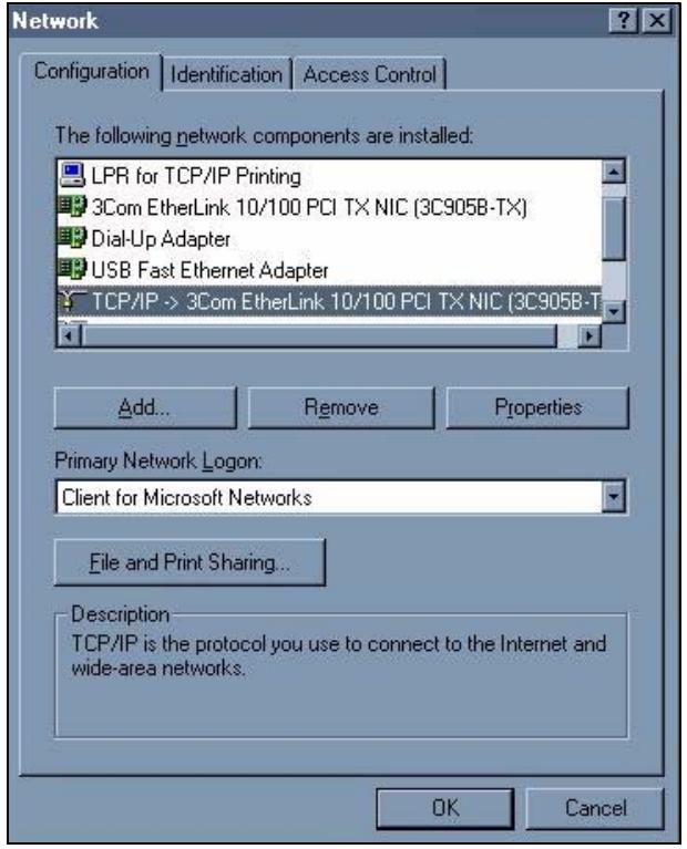
Figure 60 Windows 95/98/Me: Network: Configuration
Installing Components
The Network window Configuration tab displays a list of installed components. You need a network adapter, the TCP/IP protocol and Client for Microsoft Networks.
If you need the adapter:
1 In the Network window, click Add.
2 Select Adapter and then click Add.
3 Select the manufacturer and model of your network adapter and then click OK.
If you need TCP/IP:
1 In the Network window, click Add.
2 Select Protocol and then click Add.
3 Select Microsoft from the list of manufacturers.
4 Select TCP/IP from the list of network protocols and then click OK.
If you need Client for Microsoft Networks:
1 Click Add.
2 Select Client and then click Add.
3 Select Microsoft from the list of manufacturers.
4 Select Client for Microsoft Networks from the list of network clients and then click OK.
5 Restart your computer so the changes you made take effect.
Configuring
1 In the Network window Configuration tab, select your network adapter's TCP/IP entry and click Properties
2 Click the IP Address tab.
- If your IP address is dynamic, select Obtain an IP address automatically.
- If you have a static IP address, select Specify an IP address and type your information into the IP Address and Subnet Mask fields.
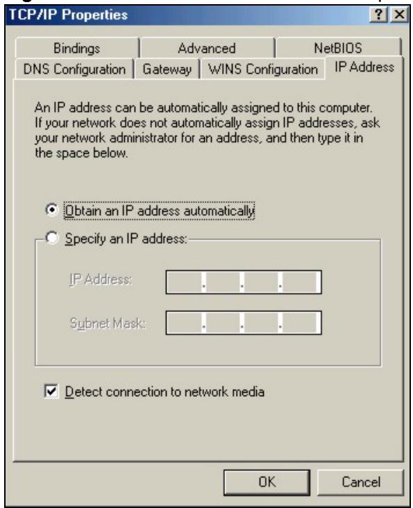
Figure 61 Windows 95/98/Me: TCP/IP Properties: IP Address
3 Click the DNS Configuration tab.
- If you do not know your DNS information, select Disable DNS.
- If you know your DNS information, select Enable DNS and type the information in the fields below (you may not need to fill them all in).
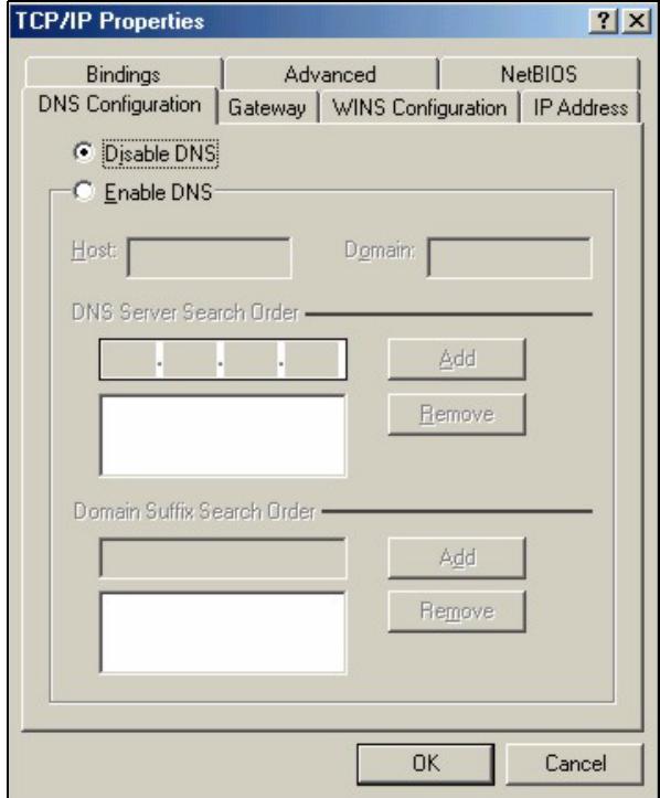
Figure 62 Windows 95/98/Me: TCP/IP Properties: DNS Configuration
4 Click the Gateway tab.
- If you do not know your gateway's IP address, remove previously installed gateways.
- If you have a gateway IP address, type it in the New gateway field and click Add.
5 Click OK to save and close the TCP/IP Properties window.
6 Click OK to close the Network window. Insert the Windows CD if prompted.
7 Turn on your ZyXEL Device and restart your computer when prompted.
Verifying Settings
1 Click Start and then Run.
2 In the Run window, type "winipcfg" and then click OK to open the IP Configuration window.
3 Select your network adapter. You should see your computer's IP address, subnet mask and default gateway.
Windows 2000/NT/XP
The following example figures use the default Windows XP GUI theme.
1 Click start (Start in Windows 2000/NT), Settings, Control Panel.

Figure 63 Windows XP: Start Menu
2 In the Control Panel, double-click Network Connections (Network and Dial-up Connections in Windows 2000/NT).
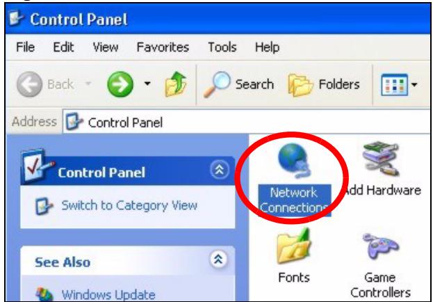
Figure 64 Windows XP: Control Panel
3 Right-click Local Area Connection and then click Properties.
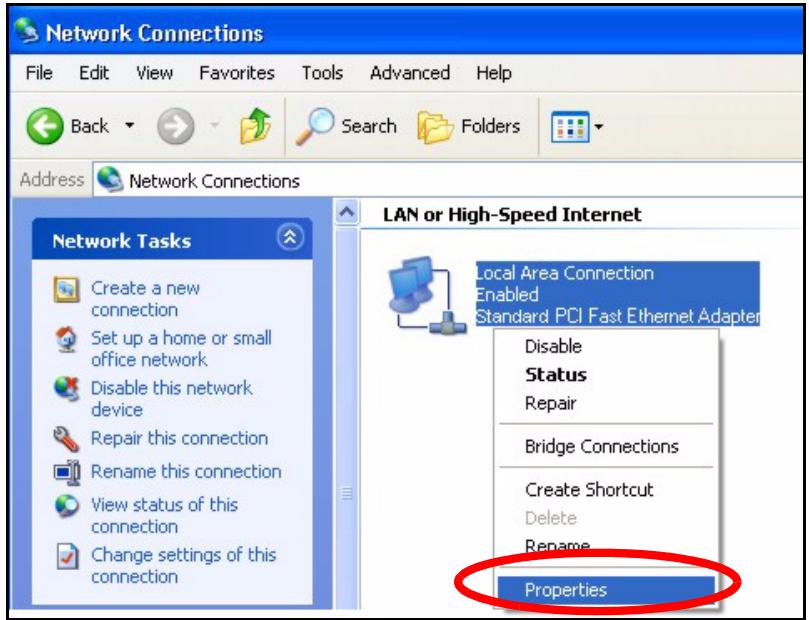
Figure 65 Windows XP: Control Panel: Network Connections: Properties
4 Select Internet Protocol (TCP/IP) (under the General tab in Win XP) and then click Properties.
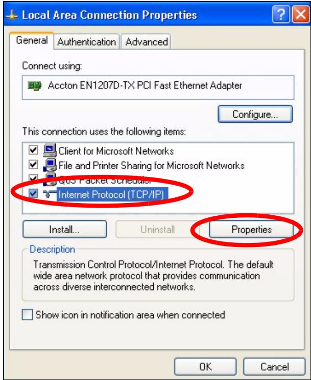
Figure 66 Windows XP: Local Area Connection Properties
5 The Internet Protocol TCP/IP Properties window opens (the General tab in Windows XP).
- If you have a dynamic IP address click Obtain an IP address automatically.
- If you have a static IP address click Use the following IP Address and fill in the IP address, Subnet mask, and Default gateway fields.
- Click Advanced.
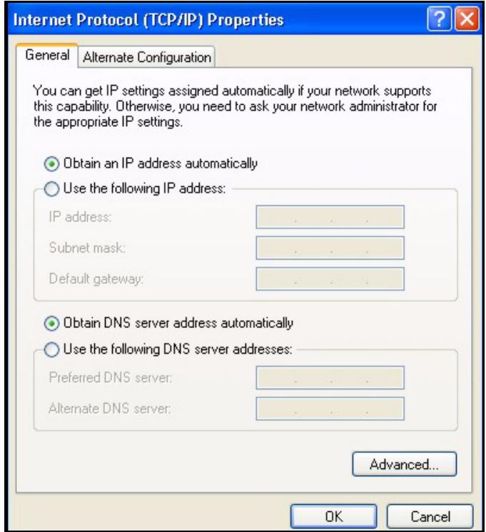
Figure 67 Windows XP: Internet Protocol (TCP/IP) Properties
6 If you do not know your gateway's IP address, remove any previously installed gateways in the IP Settings tab and click OK.
Do one or more of the following if you want to configure additional IP addresses:
- In the IP Settings tab, in IP addresses, click Add.
- In TCP/IP Address, type an IP address in IP address and a subnet mask in Subnet mask, and then click Add.
- Repeat the above two steps for each IP address you want to add.
- Configure additional default gateways in the IP Settings tab by clicking Add in Default gateways.
- In TCP/IP Gateway Address, type the IP address of the default gateway in Gateway. To manually configure a default metric (the number of transmission hops), clear the Automatic metric check box and type a metric in Metric.
- Click Add.
- Repeat the previous three steps for each default gateway you want to add.
- Click OK when finished.
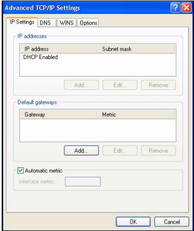
Figure 68 Windows XP: Advanced TCP/IP Properties
7 In the Internet Protocol TCP/IP Properties window (the General tab in Windows XP):
- Click Obtain DNS server address automatically if you do not know your DNS server IP address(es).
- If you know your DNS server IP address(es), click Use the following DNS server addresses, and type them in the Preferred DNS server and Alternate DNS server fields.
If you have previously configured DNS servers, click Advanced and then the DNS tab to order them.
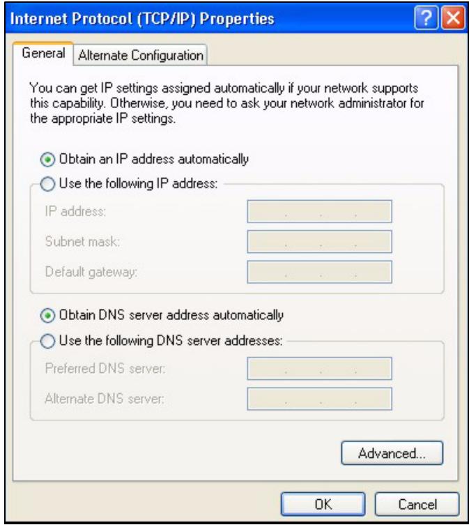
Figure 69 Windows XP: Internet Protocol (TCP/IP) Properties
8 Click OK to close the Internet Protocol (TCP/IP) Properties window.
9 Click Close (OK in Windows 2000/NT) to close the Local Area Connection Properties window.
10 Close the Network Connections window (Network and Dial-up Connections in Windows 2000/NT).
11 Turn on your ZyXEL Device and restart your computer (if prompted).
Verifying Settings
1 Click Start, All Programs, Accessories and then Command Prompt.
2 In the Command Prompt window, type "ipconfig" and then press [ENTER]. You can also open Network Connections, right-click a network connection, click Status and then click the Support tab.
Macintosh OS 8/9
1 Click the Apple menu, Control Panel and double-click TCP/IP to open the TCP/IP Control Panel.
Figure 70 Macintosh OS 8/9: Apple Menu
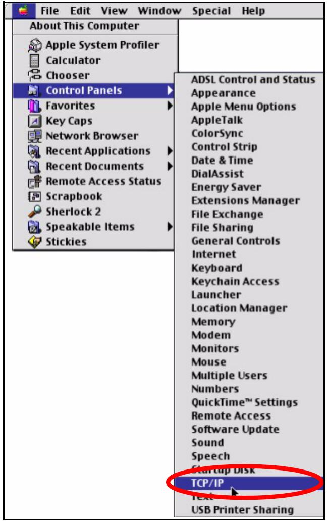
2 Select Ethernet built-in from the Connect via list.
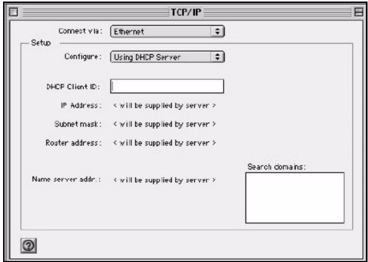
Figure 71 Macintosh OS 8/9: TCP/IP
3 For dynamically assigned settings, select Using DHCP Server from the Configure: list.
4 For statically assigned settings, do the following:
From the Configure box, select Manually.
- Type your IP address in the IP Address box.
- Type your subnet mask in the Subnet mask box.
- Type the IP address of your ZyXEL Device in the Router address box.
5 Close the TCP/IP Control Panel.
6 Click Save if prompted, to save changes to your configuration.
7 Turn on your ZyXEL Device and restart your computer (if prompted).
Verifying Settings
Check your TCP/IP properties in the TCP/IP Control Panel window.
Macintosh OS X
1 Click the Apple menu, and click System Preferences to open the System Preferences window.
Figure 72 Macintosh OS X: Apple Menu
2 Click Network in the icon bar.
- Select Automatic from the Location list.
- Select Built-in Ethernet from the Show list.
- Click the TCP/IP tab.
3 For dynamically assigned settings, select Using DHCP from the Configure list.
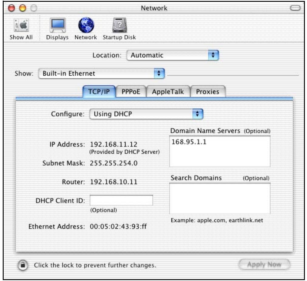
Figure 73 Macintosh OS X: Network
4 For statically assigned settings, do the following:
From the Configure box, select Manually.
- Type your IP address in the IP Address box.
- Type your subnet mask in the Subnet mask box.
- Type the IP address of your ZyXEL Device in the Router address box.
5 Click Apply Now and close the window.
6 Turn on your ZyXEL Device and restart your computer (if prompted).
Verifying Settings
Check your TCP/IP properties in the Network window.
Linux
This section shows you how to configure your computer's TCP/IP settings in Red Hat Linux 9.0. Procedure, screens and file location may vary depending on your Linux distribution and release version.

Make sure you are logged in as the root administrator.
Using the K Desktop Environment (KDE)
Follow the steps below to configure your computer IP address using the KDE.
1 Click the Red Hat button (located on the bottom left corner), select System Setting and click Network.
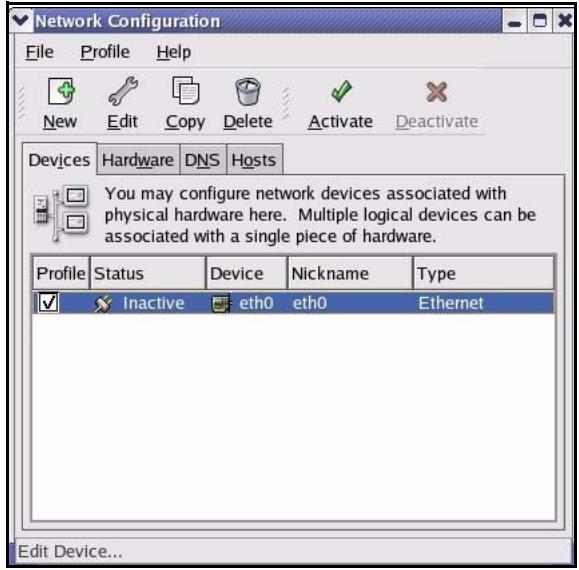
Figure 74 Red Hat 9.0: KDE: Network Configuration: Devices
2 Double-click on the profile of the network card you wish to configure. The Ethernet Device General screen displays as shown.
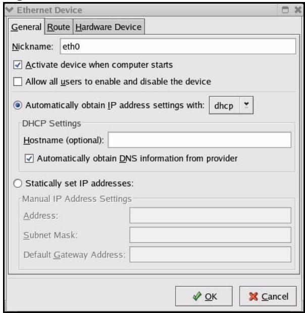
Figure 75 Red Hat 9.0: KDE: Ethernet Device: General
- If you have a dynamic IP address, click Automatically obtain IP address settings with and select dhcp from the drop down list.
- If you have a static IP address, click statically set IP Addresses and fill in the Address, Subnet mask, and Default Gateway Address fields.
3 Click OK to save the changes and close the Ethernet Device General screen.
4 If you know your DNS server IP address(es), click the DNS tab in the Network Configuration screen. Enter the DNS server information in the fields provided.
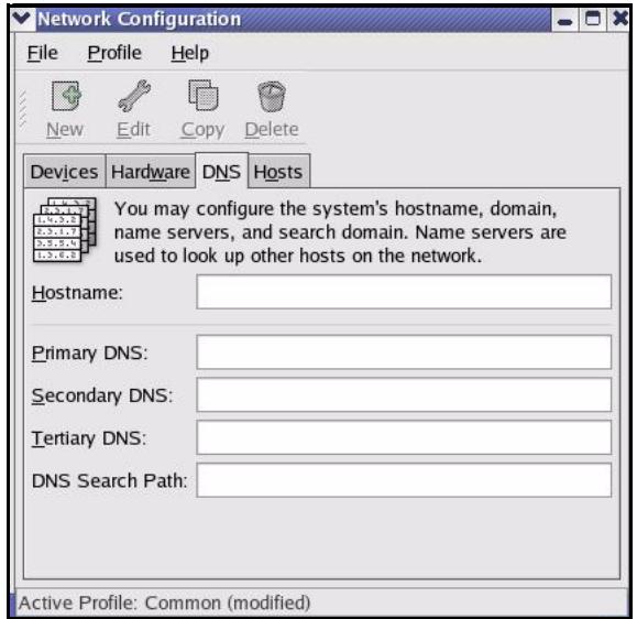
Figure 76 Red Hat 9.0: KDE: Network Configuration: DNS
5 Click the Devices tab.
6 Click the Activate button to apply the changes. The following screen displays. Click Yes to save the changes in all screens.
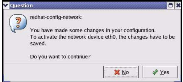
Figure 77 Red Hat 9.0: KDE: Network Configuration: Activate
7 After the network card restart process is complete, make sure the Status is Active in the Network Configuration screen.
Using Configuration Files
Follow the steps below to edit the network configuration files and set your computer IP address.
1 Assuming that you have only one network card on the computer, locate the ifconfig-eth0 configuration file (where eth0 is the name of the Ethernet card). Open the configuration file with any plain text editor.
- If you have a dynamic IP address, enter dhcpp in the BOOTPROTO= field. The following figure shows an example.
Figure 78 Red Hat 9.0: Dynamic IP Address Setting in ifconfig-eth0
DEVICE eth0
ONBOOT yes
BOOTPROTO dhcp
USERCTL no
PEERDNS yes
TYPE Ethernet
- If you have a static IP address, enter static in the BOOTPROTO= field. Type IPADDR= followed by the IP address (in dotted decimal notation) and type NETMASK= followed by the subnet mask. The following example shows an example where the static IP address is 192.168.1.10 and the subnet mask is 255.255.255.0.
Figure 79 Red Hat 9.0: Static IP Address Setting in ifconfig-eth0
DEVICE=eth0
ONBOOT=yes
BOOTPROTO=static
IPADDR=192.168.1.10
NETMASK=255.255.255.0
USERCTL=no
PEERDNS=yes
TYPE=Ethernet
2 If you know your DNS server IP address(es), enter the DNS server information in the resolv.conf file in the /etc directory. The following figure shows an example where two DNS server IP addresses are specified.
Figure 80 Red Hat 9.0: DNS Settings in resolv.conf
nameserver 172.23.5.1
nameserver 172.23.5.2
3 After you edit and save the configuration files, you must restart the network card. Enter ./network restart in the /etc/rc.d/init.d directory. The following figure shows an example.
Figure 81 Red Hat 9.0: Restart Ethernet Card
[root@localhost init.d]# network restart Shutting down interface eth0: [OK] Shutting down loopback interface: [OK] Setting network parameters: [OK] Bringing up loopback interface: [OK] Bringing up interface eth0: [OK]
Verifying Settings
Enter ifconfig in a terminal screen to check your TCP/IP properties.
Figure 82 Red Hat 9.0: Checking TCP/IP Properties
[root@localhost]# ifconfig
eth0 Link encaps:Ethernet HWaddr 00:50:BA:72:5B:44 inlet addr:172.23.19.129 Bcast:172.23.19.255 Mask:255.255.255.0 UP BROADCAST RUNNING MULTICAST MTU:1500 Metric:1 RX packets:717 errors:0 dropped:0 overruns:0 frame:0 TX packets:13 errors:0 dropped:0 overruns:0 carrier:0 collisions:0 txqueuelen:100 RX bytes:730412 (713.2 Kb) TX bytes:1570 (1.5 Kb) Interrupt:10 Base address:0x1000
[root@localhost]#
Pop-up Windows, JavaScript and Java Permissions
In order to use the web configurator you need to allow:
- Web browser pop-up windows from your device.
- JavaScripts (enabled by default).
- Java permissions (enabled by default).

Internet Explorer 6 screens are used here. Screens for other Internet Explorer versions may vary.
Internet Explorer Pop-up Blockers
You may have to disable pop-up blocking to log into your device.
Either disable pop-up blocking (enabled by default in Windows XP SP (Service Pack) 2) or allow pop-up blocking and create an exception for your device's IP address.
Disable pop-up Blockers
1 In Internet Explorer, select Tools, Pop-up Blocker and then select Turn Off Pop-up Blocker.
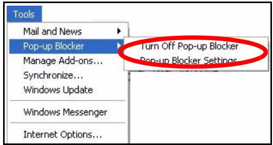
Figure 83 Pop-up Blocker
You can also check if pop-up blocking is disabled in the Pop-up Blocker section in the Privacy tab.
1 In Internet Explorer, select Tools, Internet Options, Privacy.
2 Clear the Block pop-ups check box in the Pop-up Blocker section of the screen. This disables any web pop-up blockers you may have enabled.
Figure 84 Internet Options: Privacy
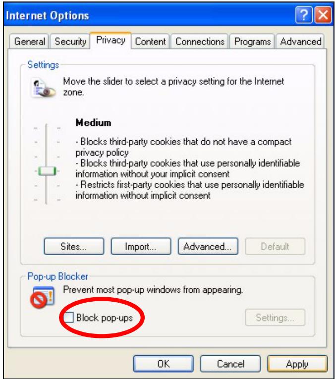
3 Click Apply to save this setting.
Enable pop-up Blockers with Exceptions
Alternatively, if you only want to allow pop-up windows from your device, see the following steps.
1 In Internet Explorer, select Tools, Internet Options and then the Privacy tab.
2 Select Settings...to open the Pop-up Blocker Settings screen.
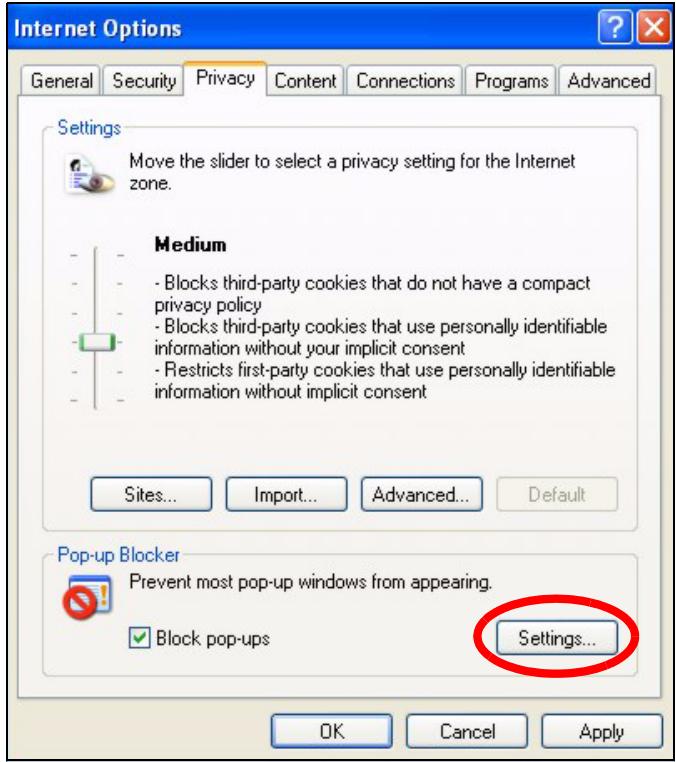
Figure 85 Internet Options: Privacy
3 Type the IP address of your device (the web page that you do not want to have blocked) with the prefix "http://". For example, http://192.168.167.1.
4 Click Add to move the IP address to the list of Allowed sites.
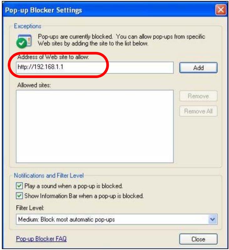
Figure 86 Pop-up Blocker Settings
5 Click Close to return to the Privacy screen.
6 Click Apply to save this setting.
JavaScript
If pages of the web configurator do not display properly in Internet Explorer, check that JavaScripts are allowed.
1 In Internet Explorer, click Tools, Internet Options and then the Security tab.
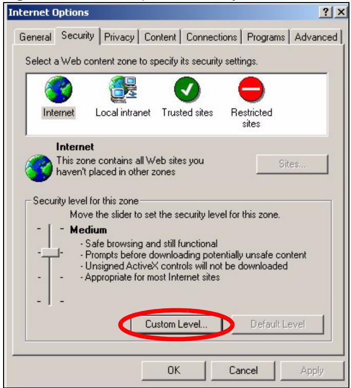
Figure 87 Internet Options: Security
2 Click the Custom Level... button.
3 Scroll down to Scripting.
4 Under Active scripting make sure that Enable is selected (the default).
5 Under Scripting of Java applets make sure that Enable is selected (the default).
6 Click OK to close the window.
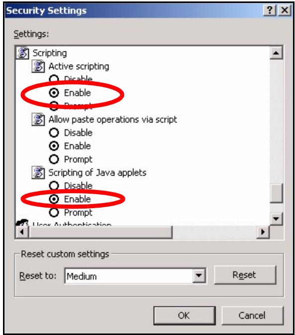
Figure 88 Security Settings - Java Scripting
Java Permissions
1 From Internet Explorer, click Tools, Internet Options and then the Security tab.
2 Click the Custom Level... button.
3 Scroll down to Microsoft VM.
4 Under Java permissions make sure that a safety level is selected.
5 Click OK to close the window.
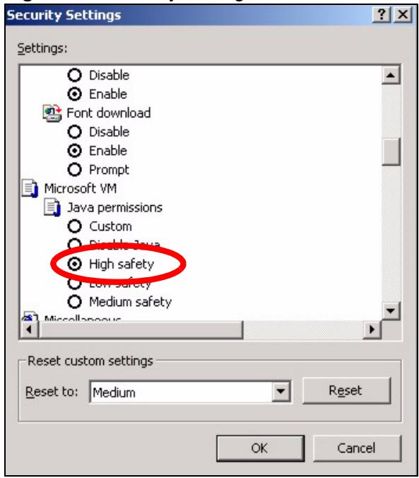
Figure 89 Security Settings - Java
JAVA (Sun)
1 From Internet Explorer, click Tools, Internet Options and then the Advanced tab.
2 Make sure that Use Java 2 for
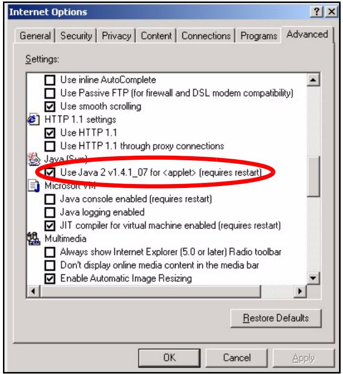
Figure 90 Java (Sun)
Wireless LANs
Wireless LAN Topologies
This section discusses ad-hoc and infrastructure wireless LAN topologies.
Ad-hoc Wireless LAN Configuration
The simplest WLAN configuration is an independent (Ad-hoc) WLAN that connects a set of computers with wireless adapters (A, B, C). Any time two or more wireless adapters are within range of each other, they can set up an independent network, which is commonly referred to as an ad-hoc network or Independent Basic Service Set (IBSS). The following diagram shows an example of notebook computers using wireless adapters to form an ad-hoc wireless LAN.
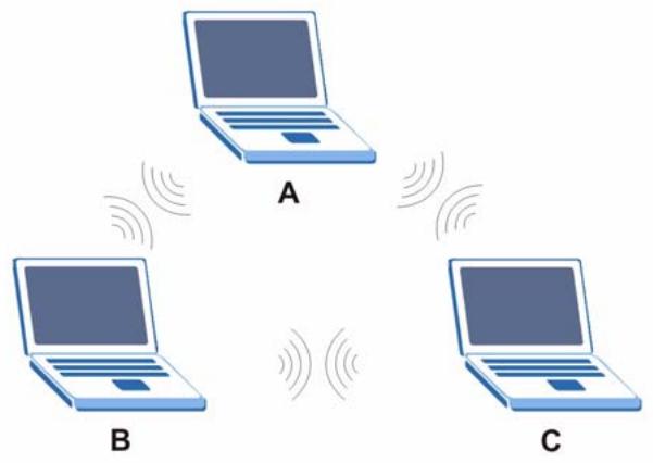
Figure 91 Peer-to-Peer Communication in an Ad-hoc Network
BSS
A Basic Service Set (BSS) exists when all communications between wireless clients or between a wireless client and a wired network client go through one access point (AP).
Intra-BSS traffic is traffic between wireless clients in the BSS. When Intra-BSS is enabled, wireless client A and B can access the wired network and communicate with each other. When Intra-BSS is disabled, wireless client A and B can still access the wired network but cannot communicate with each other.
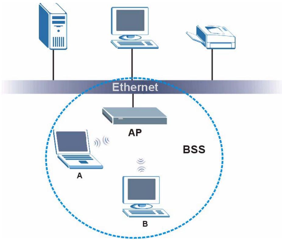
Figure 92 Basic Service Set
ESS
An Extended Service Set (ESS) consists of a series of overlapping BSSs, each containing an access point, with each access point connected together by a wired network. This wired connection between APs is called a Distribution System (DS).
This type of wireless LAN topology is called an Infrastructure WLAN. The Access Points not only provide communication with the wired network but also mediate wireless network traffic in the immediate neighborhood.
An ESSID (ESS IDentification) uniquely identifies each ESS. All access points and their associated wireless clients within the same ESS must have the same ESSID in order to communicate.
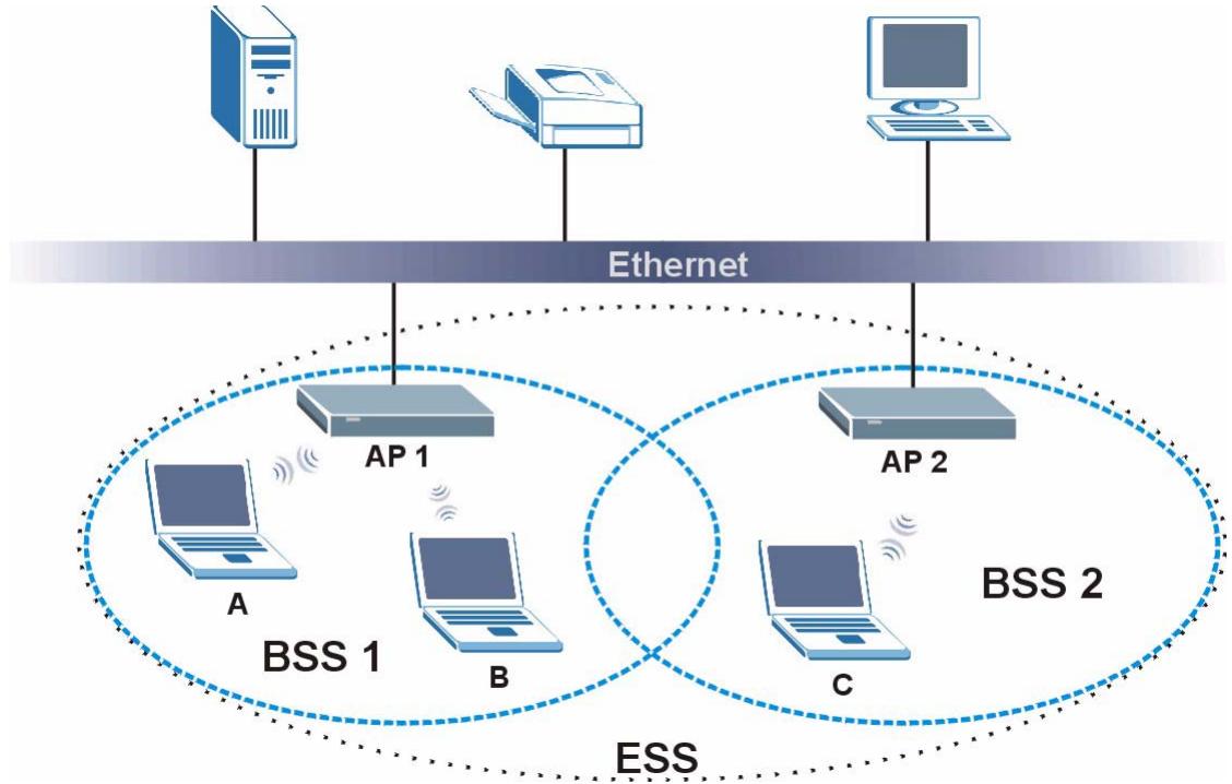
Figure 93 Infrastructure WLAN
Channel
A channel is the radio frequency(ies) used by IEEE 802.11a/b/g wireless devices. Channels available depend on your geographical area. You may have a choice of channels (for your region) so you should use a different channel than an adjacent AP (access point) to reduce interference. Interference occurs when radio signals from different access points overlap causing interference and degrading performance.
Adjacent channels partially overlap however. To avoid interference due to overlap, your AP should be on a channel at least five channels away from a channel that an adjacent AP is using. For example, if your region has 11 channels and an adjacent AP is using channel 1, then you need to select a channel between 6 or 11.
RTS/CTS
A hidden node occurs when two stations are within range of the same access point, but are not within range of each other. The following figure illustrates a hidden node. Both stations (STA) are within range of the access point (AP) or wireless gateway, but out-of-range of each other, so they cannot "hear" each other, that is they do not know if the channel is currently being used. Therefore, they are considered hidden from each other.
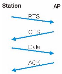
Figure 94 RTS/CTS
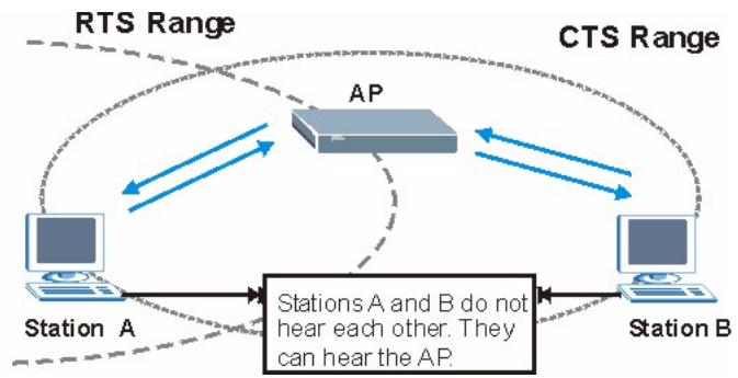
When station A sends data to the AP, it might not know that the station B is already using the channel. If these two stations send data at the same time, collisions may occur when both sets of data arrive at the AP at the same time, resulting in a loss of messages for both stations.
RTS/CTS is designed to prevent collisions due to hidden nodes. An RTS/CTS defines the biggest size data frame you can send before an RTS (Request To Send)/CTS (Clear to Send) handshake is invoked.
When a data frame exceeds the RTS/CTS value you set (between 0 to 2432 bytes), the station that wants to transmit this frame must first send an RTS (Request To Send) message to the AP for permission to send it. The AP then responds with a CTS (Clear to Send) message to all other stations within its range to notify them to defer their transmission. It also reserves and confirms with the requesting station the time frame for the requested transmission.
Stations can send frames smaller than the specified RTS/CTS directly to the AP without the RTS (Request To Send)/CTS (Clear to Send) handshake.
You should only configure RTS/CTS if the possibility of hidden nodes exists on your network and the "cost" of resending large frames is more than the extra network overhead involved in the RTS (Request To Send)/CTS (Clear to Send) handshake.
If the RTS/CTS value is greater than the Fragmentation Threshold value (see next), then the RTS (Request To Send)/CTS (Clear to Send) handshake will never occur as data frames will be fragmented before they reach RTS/CTS size.

Enabling the RTS Threshold causes redundant network overhead that could negatively affect the throughput performance instead of providing a remedy.
Fragmentation Threshold
A Fragmentation Threshold is the maximum data fragment size (between 256 and 2432 bytes) that can be sent in the wireless network before the AP will fragment the packet into smaller data frames.
A large Fragmentation Threshold is recommended for networks not prone to interference while you should set a smaller threshold for busy networks or networks that are prone to interference.
If the Fragmentation Threshold value is smaller than the RTS/CTS value (see previously) you set then the RTS (Request To Send)/CTS (Clear to Send) handshake will never occur as data frames will be fragmented before they reach RTS/CTS size.
Preamble Type
Preamble is used to signal that data is coming to the receiver. Short and Long refer to the length of the synchronization field in a packet.
Short preamble increases performance as less time sending preamble means more time for sending data. All IEEE 802.11b/g compliant wireless adapters support long preamble, but not all support short preamble.
Select Long preamble if you are unsure what preamble mode the wireless adapters support, and to provide more reliable communications in busy wireless networks.
Select Short preamble if you are sure the wireless adapters support it, and to provide more efficient communications.
Select Dynamic to have the AP automatically use short preamble when wireless adapters support it, otherwise the AP uses long preamble.

The AP and the wireless adapters MUST use the same preamble mode in order to communicate.
IEEE 802.11g Wireless LAN
IEEE 802.11g is fully compatible with the IEEE 802.11b standard. This means an IEEE 802.11b adapter can interface directly with an IEEE 802.11g access point (and vice versa) at 11 Mbps or lower depending on range. IEEE 802.11g has several intermediate rate steps between the maximum and minimum data rates. The IEEE 802.11g data rate and modulation are as follows:
Table 35 IEEE 802.11g
| DATA RATE (MBPS) | MODULATION |
| 1 | DBPSK (Differential Binary Phase Shift Keyed) |
| 2 | DQPSK (Differential Quadrature Phase Shift Keying) |
| 5.5 / 11 | CCK (Complementary Code Keying) |
| 6/9/12/18/24/36/48/54 | OFDM (Orthogonal Frequency Division Multiplexing) |
Wireless Security Overview
Wireless security is vital to your network to protect wireless communication between wireless clients, access points and the wired network.
Wireless security methods available on the ZyXEL Device are data encryption, wireless client authentication, restricting access by device MAC address and hiding the ZyXEL Device identity.
The following figure shows the relative effectiveness of these wireless security methods available on your ZyXEL Device.
Table 36 Wireless Security Levels
| SECURITY LEVEL | SECURITY TYPE |
| Least Secure Most Secure | Unique SSID (Default) |
| Unique SSID with Hide SSID Enabled | |
| MAC Address Filtering | |
| WEP Encryption | |
| IEEE802.1x EAP with RADIUS Server Authentication | |
| Wi-Fi Protected Access (WPA) | |
| WPA2 |

You must enable the same wireless security settings on the ZyXEL Device and on all wireless clients that you want to associate with it.
IEEE 802.1x
In June 2001, the IEEE 802.1x standard was designed to extend the features of IEEE 802.11 to support extended authentication as well as providing additional accounting and control features. It is supported by Windows XP and a number of network devices. Some advantages of IEEE 802.1x are:
- User based identification that allows for roaming.
- Support for RADIUS (Remote Authentication Dial In User Service, RFC 2138, 2139) for centralized user profile and accounting management on a network RADIUS server.
- Support for EAP (Extensible Authentication Protocol, RFC 2486) that allows additional authentication methods to be deployed with no changes to the access point or the wireless clients.
RADIUS
RADIUS is based on a client-server model that supports authentication, authorization and accounting. The access point is the client and the server is the RADIUS server. The RADIUS server handles the following tasks:
Authentication
Determines the identity of the users.
- Authorization
Determines the network services available to authenticated users once they are connected to the network.
- Accounting
Keeps track of the client's network activity.
RADIUS is a simple package exchange in which your AP acts as a message relay between the wireless client and the network RADIUS server.
Types of RADIUS Messages
The following types of RADIUS messages are exchanged between the access point and the RADIUS server for user authentication:
- Access-Request
Sent by an access point requesting authentication.
- Access-Reject
Sent by a RADIUS server rejecting access.
- Access-Accept
Sent by a RADIUS server allowing access.
- Access-Challenge
Sent by a RADIUS server requesting more information in order to allow access. The access point sends a proper response from the user and then sends another Access-Request message.
The following types of RADIUS messages are exchanged between the access point and the RADIUS server for user accounting:
- Accounting-Request
Sent by the access point requesting accounting.
- Accounting-Response
Sent by the RADIUS server to indicate that it has started or stopped accounting.
In order to ensure network security, the access point and the RADIUS server use a shared secret key, which is a password, they both know. The key is not sent over the network. In addition to the shared key, password information exchanged is also encrypted to protect the network from unauthorized access.
Types of EAP Authentication
This section discusses some popular authentication types: EAP-MD5, EAP-TLS, EAP-TTLS, PEAP and LEAP. Your wireless LAN device may not support all authentication types.
EAP (Extensible Authentication Protocol) is an authentication protocol that runs on top of the IEEE 802.1x transport mechanism in order to support multiple types of user authentication. By using EAP to interact with an EAP-compatible RADIUS server, an access point helps a wireless station and a RADIUS server perform authentication.
The type of authentication you use depends on the RADIUS server and an intermediary AP(s) that supports IEEE 802.1x.
For EAP-TLS authentication type, you must first have a wired connection to the network and obtain the certificate(s) from a certificate authority (CA). A certificate (also called digital IDs) can be used to authenticate users and a CA issues certificates and guarantees the identity of each certificate owner.
EAP-MD5 (Message-Digest Algorithm 5)
MD5 authentication is the simplest one-way authentication method. The authentication server sends a challenge to the wireless client. The wireless client 'proves' that it knows the password by encrypting the password with the challenge and sends back the information. Password is not sent in plain text.
However, MD5 authentication has some weaknesses. Since the authentication server needs to get the plaintext passwords, the passwords must be stored. Thus someone other than the authentication server may access the password file. In addition, it is possible to impersonate an authentication server as MD5 authentication method does not perform mutual authentication. Finally, MD5 authentication method does not support data encryption with dynamic session key. You must configure WEP encryption keys for data encryption.
EAP-TLS (Transport Layer Security)
With EAP-TLS, digital certifications are needed by both the server and the wireless clients for mutual authentication. The server presents a certificate to the client. After validating the identity of the server, the client sends a different certificate to the server. The exchange of certificates is done in the open before a secured tunnel is created. This makes user identity vulnerable to passive attacks. A digital certificate is an electronic ID card that authenticates the sender's identity. However, to implement EAP-TLS, you need a Certificate Authority (CA) to handle certificates, which imposes a management overhead.
EAP-TTLS (Tunnelled Transport Layer Service)
EAP-TTLS is an extension of the EAP-TLS authentication that uses certificates for only the server-side authentications to establish a secure connection. Client authentication is then done by sending username and password through the secure connection, thus client identity is protected. For client authentication, EAP-TTLS supports EAP methods and legacy authentication methods such as PAP, CHAP, MS-CHAP and MS-CHAP v2.
PEAP (Protected EAP)
Like EAP-TTLS, server-side certificate authentication is used to establish a secure connection, then use simple username and password methods through the secured connection to authenticate the clients, thus hiding client identity. However, PEAP only supports EAP methods, such as EAP-MD5, EAP-MSCHAPv2 and EAP-GTC (EAP-Generic Token Card), for client authentication. EAP-GTC is implemented only by Cisco.
LEAP
LEAP (Lightweight Extensible Authentication Protocol) is a Cisco implementation of IEEE 802.1x.
Dynamic WEP Key Exchange
The AP maps a unique key that is generated with the RADIUS server. This key expires when the wireless connection times out, disconnects or reauthentication times out. A new WEP key is generated each time reauthentication is performed.
If this feature is enabled, it is not necessary to configure a default encryption key in the Wireless screen. You may still configure and store keys here, but they will not be used while Dynamic WEP is enabled.

EAP-MD5 cannot be used with Dynamic WEP Key Exchange
For added security, certificate-based authentications (EAP-TLS, EAP-TTLS and PEAP) use dynamic keys for data encryption. They are often deployed in corporate environments, but for public deployment, a simple user name and password pair is more practical. The following table is a comparison of the features of authentication types.
Table 37 Comparison of EAP Authentication Types
| EAP-MD5 | EAP-TLS | EAP-TTLS | PEAP | LEAP | |
| Mutual Authentication | No | Yes | Yes | Yes | Yes |
| Certificate – Client | No | Yes | Optional | Optional | No |
| Certificate – Server | No | Yes | Yes | Yes | No |
| Dynamic Key Exchange | No | Yes | Yes | Yes | Yes |
| Credential Integrity | None | Strong | Strong | Strong | Moderate |
| Deployment Difficulty | Easy | Hard | Moderate | Moderate | Moderate |
| Client Identity Protection | No | No | Yes | Yes | No |
WPA and WPA2
Wi-Fi Protected Access (WPA) is a subset of the IEEE 802.11i standard. WPA2 (IEEE 802.11i) is a wireless security standard that defines stronger encryption, authentication and key management than WPA.
Key differences between WPA or WPA2 and WEP are improved data encryption and user authentication.
If both an AP and the wireless clients support WPA2 and you have an external RADIUS server, use WPA2 for stronger data encryption. If you don't have an external RADIUS server, you should use WPA2-PSK (WPA2-Pre-Shared Key) that only requires a single (identical) password entered into each access point, wireless gateway and wireless client. As long as the passwords match, a wireless client will be granted access to a WLAN.
If the AP or the wireless clients do not support WPA2, just use WPA or WPA-PSK depending on whether you have an external RADIUS server or not.
Select WEP only when the AP and/or wireless clients do not support WPA or WPA2. WEP is less secure than WPA or WPA2.
Encryption
Both WPA and WPA2 improve data encryption by using Temporal Key Integrity Protocol (TKIP), Message Integrity Check (MIC) and IEEE 802.1x. WPA and WPA2 use Advanced Encryption Standard (AES) in the Counter mode with Cipher block chaining Message authentication code Protocol (CCMP) to offer stronger encryption than TKIP.
TKIP uses 128-bit keys that are dynamically generated and distributed by the authentication server. AES (Advanced Encryption Standard) is a block cipher that uses a 256-bit mathematical algorithm called Rijndael. They both include a per-packet key mixing function, a Message Integrity Check (MIC) named Michael, an extended initialization vector (IV) with sequencing rules, and a re-keying mechanism.
WPA and WPA2 regularly change and rotate the encryption keys so that the same encryption key is never used twice.
The RADIUS server distributes a Pairwise Master Key (PMK) key to the AP that then sets up a key hierarchy and management system, using the PMK to dynamically generate unique data encryption keys to encrypt every data packet that is wirelessly communicated between the AP and the wireless clients. This all happens in the background automatically.
The Message Integrity Check (MIC) is designed to prevent an attacker from capturing data packets, altering them and resending them. The MIC provides a strong mathematical function in which the receiver and the transmitter each compute and then compare the MIC. If they do not match, it is assumed that the data has been tampered with and the packet is dropped.
By generating unique data encryption keys for every data packet and by creating an integrity checking mechanism (MIC), with TKIP and AES it is more difficult to decrypt data on a Wi-Fi network than WEP and difficult for an intruder to break into the network.
The encryption mechanisms used for WPA(2) and WPA(2)-PSK are the same. The only difference between the two is that WPA(2)-PSK uses a simple common password, instead of user-specific credentials. The common-password approach makes WPA(2)-PSK susceptible to brute-force password-guessing attacks but it's still an improvement over WEP as it employs a consistent, single, alphanumeric password to derive a PMK which is used to generate unique temporal encryption keys. This prevent all wireless devices sharing the same encryption keys. (a weakness of WEP)
User Authentication
WPA and WPA2 apply IEEE 802.1x and Extensible Authentication Protocol (EAP) to authenticate wireless clients using an external RADIUS database. WPA2 reduces the number of key exchange messages from six to four (CCMP 4-way handshake) and shortens the time required to connect to a network. Other WPA2 authentication features that are different from WPA include key caching and pre-authentication. These two features are optional and may not be supported in all wireless devices.
Key caching allows a wireless client to store the PMK it derived through a successful authentication with an AP. The wireless client uses the PMK when it tries to connect to the same AP and does not need to go with the authentication process again.
Pre-authentication enables fast roaming by allowing the wireless client (already connecting to an AP) to perform IEEE 802.1x authentication with another AP before connecting to it.
Wireless Client WPA Suppliers
A wireless client supplicant is the software that runs on an operating system instructing the wireless client how to use WPA. At the time of writing, the most widely available supplicant is the WPA patch for Windows XP, Funk Software's Odyssey client.
The Windows XP patch is a free download that adds WPA capability to Windows XP's built-in "Zero Configuration" wireless client. However, you must run Windows XP to use it.
WPA(2) with RADIUS Application Example
You need the IP address of the RADIUS server, its port number (default is 1812), and the RADIUS shared secret. A WPA(2) application example with an external RADIUS server looks as follows. "A" is the RADIUS server. "DS" is the distribution system.
1 The AP passes the wireless client's authentication request to the RADIUS server.
2 The RADIUS server then checks the user's identification against its database and grants or denies network access accordingly.
3 The RADIUS server distributes a Pairwise Master Key (PMK) key to the AP that then sets up a key hierarchy and management system, using the pair-wise key to dynamically generate unique data encryption keys to encrypt every data packet that is wirelessly communicated between the AP and the wireless clients.
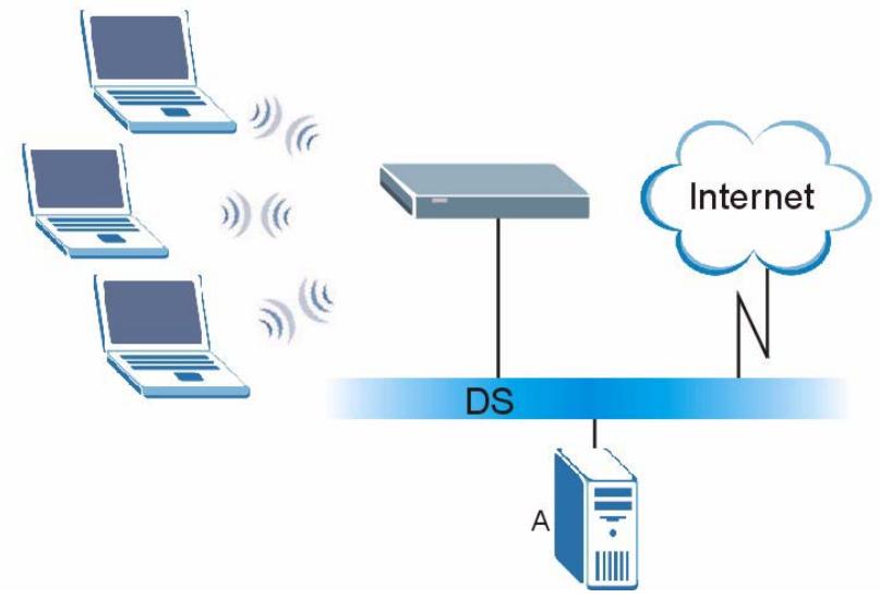
Figure 95 WPA(2) with RADIUS Application Example
WPA(2)-PSK Application Example
A WPA(2)-PSK application looks as follows.
1 First enter identical passwords into the AP and all wireless clients. The Pre-Shared Key (PSK) must consist of between 8 and 63 ASCII characters or 64 hexadecimal characters (including spaces and symbols).
2 The AP checks each wireless client's password and (only) allows it to join the network if the password matches.
3 The AP and wireless clients use the pre-shared key to generate a common PMK (Pairwise Master Key).
4 The AP and wireless clients use the TKIP or AES encryption process to encrypt data exchanged between them.
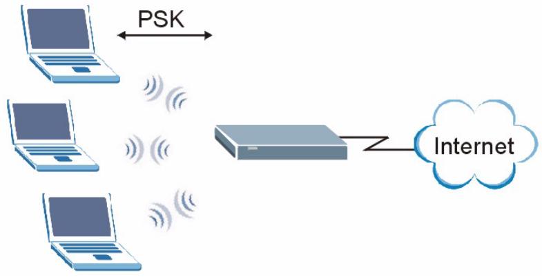
Figure 96 WPA(2)-PSK Authentication
Security Parameters Summary
Refer to this table to see what other security parameters you should configure for each Authentication Method/ key management protocol type. MAC address filters are not dependent on how you configure these security features.
Table 38 Wireless Security Relational Matrix
| AUTHENTICATION METHOD/ KEYMANAGEMENT PROTOCOL | ENCRYPTION METHOD | ENTERMANUAL KEY | IEEE 802.1X |
| Open | None | No | Disable |
| Enable without Dynamic WEP Key | |||
| Open | WEP | No | Enable with Dynamic WEP Key |
| Yes | Enable without Dynamic WEP Key | ||
| Yes | Disable | ||
| Shared | WEP | No | Enable with Dynamic WEP Key |
| Yes | Enable without Dynamic WEP Key | ||
| Yes | Disable | ||
| WPA | TKIP/AES | No | Enable |
| WPA-PSK | TKIP/AES | Yes | Disable |
| WPA2 | TKIP/AES | No | Enable |
| WPA2-PSK | TKIP/AES | Yes | Disable |
Antenna Overview
An antenna couples RF signals onto air. A transmitter within a wireless device sends an RF signal to the antenna, which propagates the signal through the air. The antenna also operates in reverse by capturing RF signals from the air.
Positioning the antennas properly increases the range and coverage area of a wireless LAN.
Antenna Characteristics
Frequency
An antenna in the frequency of 2.4GHz (IEEE 802.11b) or 5GHz (IEEE 802.11a) is needed to communicate efficiently in a wireless LAN.
Radiation Pattern
A radiation pattern is a diagram that allows you to visualize the shape of the antenna's coverage area.
Antenna Gain
Antenna gain, measured in dB (decibel), is the increase in coverage within the RF beam width. Higher antenna gain improves the range of the signal for better communications.
For an indoor site, each 1 dB increase in antenna gain results in a range increase of approximately 2.5% . For an unobstructed outdoor site, each 1dB increase in gain results in a range increase of approximately 5% . Actual results may vary depending on the network environment.
Antenna gain is sometimes specified in dBi, which is how much the antenna increases the signal power compared to using an isotropic antenna. An isotropic antenna is a theoretical perfect antenna that sends out radio signals equally well in all directions. dBi represents the true gain that the antenna provides.
Types of Antennas for WLAN
There are two types of antennas used for wireless LAN applications.
- Omni-directional antennas send the RF signal out in all directions on a horizontal plane. The coverage area is torus-shaped (like a donut) which makes these antennas ideal for a room environment. With a wide coverage area, it is possible to make circular overlapping coverage areas with multiple access points.
- Directional antennas concentrate the RF signal in a beam, like a flashlight does with the light from its bulb. The angle of the beam determines the width of the coverage pattern. Angles typically range from 20 degrees (very directional) to 120 degrees (less directional). Directional antennas are ideal for hallways and outdoor point-to-point applications.
Positioning Antennas
In general, antennas should be mounted as high as practically possible and free of obstructions. In point-to-point application, position both antennas at the same height and in a direct line of sight to each other to attain the best performance.
For omni-directional antennas mounted on a table, desk, and so on, point the antenna up. For omni-directional antennas mounted on a wall or ceiling, point the antenna down. For a single AP application, place omni-directional antennas as close to the center of the coverage area as possible.
For directional antennas, point the antenna in the direction of the desired coverage area.
Customer Support
Please have the following information ready when you contact customer support.
Required Information
Product model and serial number.
Warranty Information.
- Date that you received your device.
- Brief description of the problem and the steps you took to solve it.
Corporate Headquarters (Worldwide)
- Support E-mail: support@zyxel.com.tw
Sales E-mail: sales@zyxel.com.tw
Telephone: +886-3-578-3942
Fax: +886-3-578-2439 - Web Site: www.zyxel.com, www.europe.zyxel.com
- FTP Site: ftp.zyxel.com, ftp.europe.zyxel.com
- Regular Mail: ZyXEL Communications Corp., 6 Innovation Road II, Science Park, Hsinchu 300, Taiwan
Costa Rica
- Support E-mail: soporte@zyxel.co.cr
Sales E-mail: sales@zyxel.co.cr
Telephone: +506-2017878
Fax: +506-2015098 - Web Site: www.zyxel.co.cr
- FTP Site: ftp.zyxel.co.kr
- Regular Mail: ZyXEL Costa Rica, Plaza Roble Escazú, Etapa El Patio, Tercer Piso, San José, Costa Rica
Czech Republic
E-mail: info@cz.zyxel.com
Telephone: +420-241-091-350
Fax: +420-241-091-359
Web Site: www.zyxel.cz
- Regular Mail: ZyXEL Communications, Czech s.r.o., Modranská 621, 143 01 Praha 4 - Modrany, Ceská Republika
Denmark
- Support E-mail: support@zyxel.dk
Sales E-mail: sales@zyxel.dk
Telephone: +45-39-55-07-00
Fax: +45-39-55-07-07 - Web Site: www.zyxel.dk
- Regular Mail: ZyXEL Communications A/S, Columbusvej, 2860 Soeborg, Denmark
Finland
- Support E-mail: support@zyxel.fi
Sales E-mail: sales@zyxel.fi
Telephone: +358-9-4780-8411
Fax: +358-9-4780 8448
Web Site: www.zyxel.fi - Regular Mail: ZyXEL Communications Oy, Malminkaari 10, 00700 Helsinki, Finland
France
E-mail: info@zyxel.fr
Telephone: +33-4-72-52-97-97
Fax: +33-4-72-52-19-20
Web Site: www.zyxel.fr
- Regular Mail: ZyXEL France, 1 rue des Vergers, Bat. 1 / C, 69760 Limonest, France
Germany
- Support E-mail: support@zyxel.de
Sales E-mail: sales@zyxel.de
Telephone: +49-2405-6909-0
Fax: +49-2405-6909-99 - Web Site: www.zyxel.de
- Regular Mail: ZyXEL Deutschland GmbH., Adenauerstr. 20/A2 D-52146, Wuerselen, Germany
Hungary
- Support E-mail: support@zyxel.hu
Sales E-mail: info@zyxel.hu
Telephone: +36-1-3361649
Fax: +36-1-3259100
Web Site: www.zyxel.hu
Regular Mail: ZyXEL Hungary, 48, Zoldlomb Str., H-1025, Budapest, Hungary
Kazakhstan
- Support: http://zyxel.kz/support
Sales E-mail: sales@zyxel.kz
Telephone: +7-3272-590-698
Fax: +7-3272-590-689
Web Site: www.zyxel.kz
- Regular Mail: ZyXEL Kazakhstan, 43, Dostyk ave., Office 414, Dostyk Business Centre, 050010, Almaty, Republic of Kazakhstan
North America
- Support E-mail: support@zyxel.com
- Sales E-mail: sales@zyxel.com
- Telephone: +1-800-255-4101, +1-714-632-0882
Fax: +1-714-632-0858
Web Site: www.us.zyxel.com - FTP Site: ftp.us.zyxel.com
- Regular Mail: ZyXEL Communications Inc., 1130 N. Miller St., Anaheim, CA 92806-2001, U.S.A.
Norway
- Support E-mail: support@zyxel.no
Sales E-mail: sales@zyxel.no
Telephone: +47-22-80-61-80
Fax: +47-22-80-61-81
Web Site: www.zyxel.no
Regular Mail: ZyXEL Communications A/S, Nils Hansens vei 13, 0667 Oslo, Norway
Poland
E-mail: info@pl.zyxel.com
Telephone: +48 (22) 333 8250
Fax: +48 (22) 333 8251
Web Site: www.pl.zyxel.com
Regular Mail: ZyXEL Communications, ul. Okrzej 1A, 03-715 Warszawa, Poland
Russia
- Support: http://zyxel.ru/support
Sales E-mail: sales@zyxel.ru
Telephone: +7-095-542-89-29
Fax: +7-095-542-89-25
Web Site: www.zyxel.ru - Regular Mail: ZyXEL Russia, Ostrovityanova 37a Str., Moscow, 117279, Russia
Spain
- Support E-mail: support@zyxel.es
Sales E-mail: sales@zyxel.es
Telephone: +34-902-195-420
Fax: +34-913-005-345
Web Site: www.zyxel.es
- Regular Mail: ZyXEL Communications, Arte, 215^a planta, 28033 Madrid, Spain
Sweden
- Support E-mail: support@zyxel.se
Sales E-mail: sales@zyxel.se
Telephone: +46-31-744-7700
Fax: +46-31-744-7701
Web Site: www.zyxel.se - Regular Mail: ZyXEL Communications A/S, Sjöporten 4, 41764 Göteborg, Sweden
Ukraine
- Support E-mail: support@ua.zyxel.com
- Sales E-mail: sales@ua.zyxel.com
Telephone: +380-44-247-69-78
Fax: +380-44-494-49-32
Web Site: www.ua.zyxel.com - Regular Mail: ZyXEL Ukraine, 13, Pimonenko Str., Kiev, 04050, Ukraine
United Kingdom
- Support E-mail: support@zyxel.co.uk
Sales E-mail: sales@zyxel.co.uk - Telephone: +44-1344 303044, 08707 555779 (UK only)
Fax: +44-1344 303034
Web Site: www.zyxel.co.uk
FTP Site: ftp.zyxel.co.uk - Regular Mail: ZyXEL Communications UK, Ltd.,11 The Courtyard, Eastern Road, Bracknell, Berkshire, RG12 2XB, United Kingdom (UK)
“+” is the (prefix) number you dial to make an international telephone call.
Legal Information
Copyright
Copyright © 2006 by ZyXEL Communications Corporation.
The contents of this publication may not be reproduced in any part or as a whole, transcribed, stored in a retrieval system, translated into any language, or transmitted in any form or by any means, electronic, mechanical, magnetic, optical, chemical, photocopying, manual, or otherwise, without the prior written permission of ZyXEL Communications Corporation.
Published by ZyXEL Communications Corporation. All rights reserved.
Disclaimer
ZyXEL does not assume any liability arising out of the application or use of any products, or software described herein. Neither does it convey any license under its patent rights nor the patent rights of others. ZyXEL further reserves the right to make changes in any products described herein without notice. This publication is subject to change without notice.
Trademarks
ZyNOS (ZyXEL Network Operating System) is a registered trademark of ZyXEL Communications, Inc. Other trademarks mentioned in this publication are used for identification purposes only and may be properties of their respective owners.
Certifications
Federal Communications Commission (FCC) Interference Statement
The device complies with Part 15 of FCC rules. Operation is subject to the following two conditions:
- This device may not cause harmful interference.
- This device must accept any interference received, including interference that may cause undesired operations.
This device has been tested and found to comply with the limits for a Class B digital device pursuant to Part 15 of the FCC Rules. These limits are designed to provide reasonable protection against harmful interference in a residential installation. This device generates, uses, and can radiate radio frequency energy, and if not installed and used in accordance with the instructions, may cause harmful interference to radio communications. However, there is no guarantee that interference will not occur in a particular installation.
If this device does cause harmful interference to radio/television reception, which can be determined by turning the device off and on, the user is encouraged to try to correct the interference by one or more of the following measures:
1 Reorient or relocate the receiving antenna.
2 Increase the separation between the equipment and the receiver.
3 Connect the equipment into an outlet on a circuit different from that to which the receiver is connected.
4 Consult the dealer or an experienced radio/TV technician for help.
FCC Radiation Exposure Statement
- This transmitter must not be co-located or operating in conjunction with any other antenna or transmitter.
- IEEE 802.11b or 802.11g operation of this product in the U.S.A. is firmware-limited to channels 1 through 11.
- To comply with FCC RF exposure compliance requirements, a separation distance of at least 20~cm must be maintained between the antenna of this device and all persons.
注意!
依據低功率電波輻射性電機管理辦法
Changes or modifications not expressly approved by the party responsible for compliance could void the user's authority to operate the equipment.
This device has been designed for the WLAN 2.4 GHz network throughout the EC region and Switzerland, with restrictions in France.
This Class B digital apparatus complies with Canadian ICES-003.
Viewing Certifications
1 Go to http://www.zyxel.com.
2 Select your product on the ZyXEL home page to go to that product's page.
3 Select the certification you wish to view from this page.
ZyXEL Limited Warranty
ZyXEL warrants to the original end user (purchaser) that this product is free from any defects in materials or workmanship for a period of up to two years from the date of purchase. During the warranty period, and upon proof of purchase, should the product have indications of failure due to faulty workmanship and/or materials, ZyXEL will, at its discretion, repair or replace the defective products or components without charge for either parts or labor, and to whatever extent it shall deem necessary to restore the product or components to proper operating condition. Any replacement will consist of a new or re-manufactured functionally equivalent product of equal or higher value, and will be solely at the discretion of ZyXEL. This warranty shall not apply if the product has been modified, misused, tampered with, damaged by an act of God, or subjected to abnormal working conditions.
Note
Repair or replacement, as provided under this warranty, is the exclusive remedy of the purchaser. This warranty is in lieu of all other warranties, express or implied, including any implied warranty of merchantability or fitness for a particular use or purpose. ZyXEL shall in no event be held liable for indirect or consequential damages of any kind to the purchaser.
To obtain the services of this warranty, contact ZyXEL's Service Center for your Return Material Authorization number (RMA). Products must be returned Postage Prepaid. It is recommended that the unit be insured when shipped. Any returned products without proof of purchase or those with an out-dated warranty will be repaired or replaced (at the discretion of ZyXEL) and the customer will be billed for parts and labor. All repaired or replaced products will be shipped by ZyXEL to the corresponding return address, Postage Paid. This warranty gives you specific legal rights, and you may also have other rights that vary from country to country.
Registration
Register your product online to receive e-mail notices of firmware upgrades and information at www.zyxel.com for global products, or at www.us.zyxel.com for North American products.
Index
A
access 96
adaptor 95
address 51, 96, 101
address assignment 51
Advanced Encryption Standard See AES.
advanced screens 46
AES 101, 102, 138
antenna 101, 104
directional 141
gain 141
omni-directional 141
AP (access point) 131
approvals 104
association list 49
auto MDI/MDI-X 101
auto-negotiating 101
B
back up 91
backup 89, 91
Basic Service Set see BSS
browser settings 96
BSS 129
C
CA 136
cables 95
Certificate Authority See CA.
certifications 147
notices 148
viewing 148
channel 65, 131
interference 131
channel ID 61, 68, 71
command interface 26
configuration 46, 92
configuration file 91, 97
connections 101
contact information 143
copyright 147
coverage area 104
CTS (Clear to Send) 132
customer support 143
D
data encryption 65
data modulation 104
data rate 104
default IP address 101
default settings 91, 93, 96, 97
depth 101
DHCP 96
DHCP client 101
DHCP relay 101
diagnostic tools 102
diagnostics 47, 102
dimensions 101
disclaimer 147
disconnect 92, 94
dynamic WEP 102
dynamic WEP key exchange 137
E
EAP 101
EAP Authentication 135
encryption 65, 101, 102, 103, 138
error log 102
ESS 130
ESSID 97
ethernet ports 101
European plug standards 105
Extended Service Set, See ESS 130
Extensible Authentication Protocol (EAP) 102
login 96
logs 89, 90, 102
F
factory defaults 91, 93, 96
FCC interference statement 147
features 101
file transfer protocol 97
firmware 93, 94, 97
fragmentation threshold 132
frequency 61
frequency range 104
FTP 26, 97
H
hardware 102
height 101
hidden node 131
host ID 51
humidity (operation) 101
humidity (storage) 101
1
IANA 51
IBSS 129
IEEE 802.11g 133
IEEE 802.1x 101, 102
IEEE standards compliance 101
Independent Basic Service Set See IBSS 129
initialization vector (IV) 138
interference 98
Internet access 98
Internet browser settings 96
IP address 51, 92, 96, 101
L
language 89
LEDs 27,95,98,102
M
MAC address 63, 101, 102, 103
maintenance 89
management 89, 102
managing the device
good habits 27
using FTP. See FTP.
using Telnet. See command interface.
using the command interface. See command interface.
using the web configurator. See web configurator.
mask 51
Media Access Control address 63
Message Integrity Check (MIC) 138
modes 102
modulation 104
N
navigation panel 46
network congestion 98
network disconnect 92, 94
network number 51
network statistics 47
North American plug standards 106
0
operating frequency 61
operating humidity 101
operatingsmodes102
operating temperature 101
OTIST 102
output power 104
output power management 104
P
packet log 102
packet statistics 48
Pairwise Master Key (PMK) 138, 139
password 89, 91, 96, 97, 101
port status 48
ports 101
power 104
power adaptor 95
power adaptor specifications 105
power cord 95
power management 104
power requirements 101
preamble mode 133
priorities 59
private IP address 51
private networks 51
problem solving 95
product registration 149
protocol support 101
PSK 138
Q
QoS 59
QoS priorities 59
R
RADIUS 134
message types 135
messages 135
shared secret key 135
registration
product 149
related documentation 3
reset 93, 96, 97, 102, 103
restart
automatic 92, 94
restore 89, 91, 92
RF frequency range 104
RF interference 98
RJ-45 101
roaming 102
rom-0 file 91
romfile 91
RTS (Request To Send) 132
threshold 131, 132
s
safety approvals 104
safety warnings 6
Secure Sockets Layer (SSL) 103
security 65, 101, 102
sensitivity 104
settings 47
signal interference 98
signal strength 49, 50, 65, 98
size 101
SSID 65
standards compliance 101
statistics 47, 48
status 47
storage humidity 101
storage temperature 101
subset 96
subset mask 51
default 101
syntax conventions 4
syslog 102
system status 47
T
TCP/IP setup 91
Telnet 97
temperature (operation) 101
temperature (storage) 101
Temporal Key Integrity Protocol (TKIP) 138
tools (diagnostic) 102
trace log 102
trademarks 147
transmission types 104
troubleshooting 95
U
upload configuration 92
upload firmware 93
W
warranty 149
note 149
WDS 65
web configurator 26
weight 101
WEP 101, 102, 103
width 101
Wi-Fi Multimedia QoS 59
Wi-Fi Protected Access 137
wireless association 47, 49
wireless channel 97
wireless client WPA supplicants 139
Wireless Distribution System (WDS) 65, 102
wireless frequency 61
wireless interference 98
wireless LAN 97, 103
wireless modes 101
wireless security 65, 97, 101, 102, 133
wireless sensitivity 104
wireless signal strength 65
wireless specifications 104
WLAN
interference 131
security parameters 140
WMM 59
WMM priorities 59
WPA 101, 102, 137
key caching 138
pre-authentication 138
user authentication 138
vs WPA-PSK 138
wireless client supplicant 139
with RADIUS application example 139
WPA2 137
user authentication 138
vs WPA2-PSK 138
wireless client supplicant 139
with RADIUS application example 139
WPA2-Pre-Shared Key 137
WPA2-PSK 137, 138
application example 139
WPA-PSK 137, 138
application example 139