
V-630 - Modem/Router ZYXEL - Free user manual and instructions
Find the device manual for free V-630 ZYXEL in PDF.
| Brand | ZYXEL |
| Model | V-630 |
| Product type | ADSL2+ Modem/Router with Wi-Fi access point |
| Dimensions (L x D x H) | 180 x 120 x 30 mm |
| Weight | 300 g |
| Power supply | 12V DC, 1A power adapter |
| Power consumption | 10 W maximum |
| ADSL standards | ADSL2+ (G.992.5) compatible with ADSL and ADSL2 |
| Wi-Fi standard | 802.11g/b, up to 54 Mbit/s |
| Physical ports | 1 ADSL port (RJ-11), 4 Ethernet 10/100 ports (RJ-45), 1 USB port (for printer or storage) |
| Router functions | NAT, DHCP server, SPI firewall, QoS, VPN pass-through |
| Antennas | 1 removable external antenna (2 dBi) |
| Wi-Fi security | WEP 64/128 bits, WPA, WPA2-PSK |
| Maintenance and cleaning | Disconnect the device before cleaning. Use a soft, dry cloth. Do not use liquid or abrasive products. |
| Operating conditions | Temperature: 0 to 40 °C, humidity: 10 to 90% non-condensing |
| Certifications | CE, FCC, NMB-003 (Canada) |
| Spare parts and repairability | Not user-repairable. No spare parts available. Contact ZYXEL technical support. |
| Package contents | V-630 modem/router, power adapter, ADSL cable, RJ-45 Ethernet cable, Wi-Fi antenna, quick installation guide |
Frequently Asked Questions - V-630 ZYXEL
User questions about V-630 ZYXEL
0 question about this device. Answer the ones you know or ask your own.
Ask a new question about this device
Download the instructions for your Modem/Router in PDF format for free! Find your manual V-630 - ZYXEL and take your electronic device back in hand. On this page are published all the documents necessary for the use of your device. V-630 by ZYXEL.
USER MANUAL V-630 ZYXEL
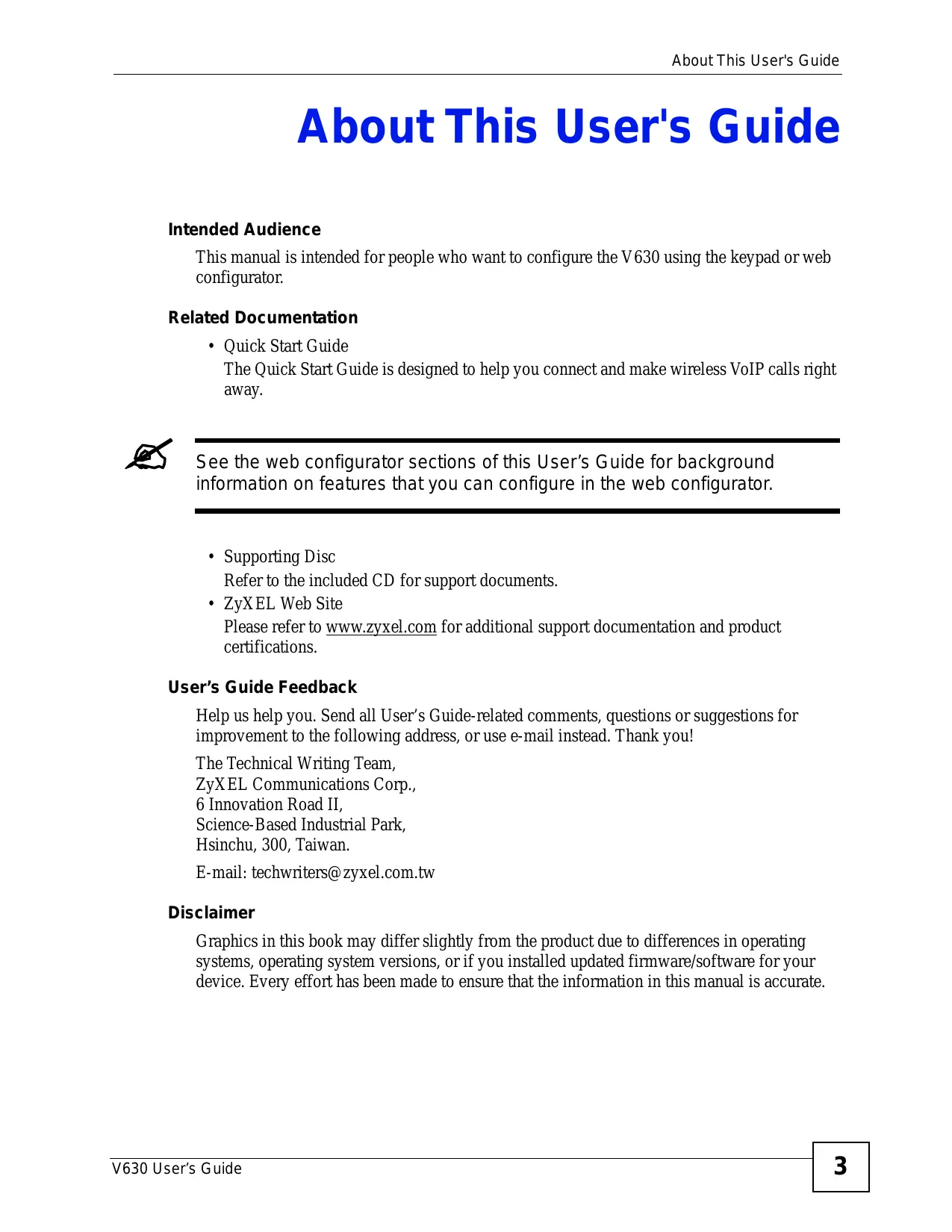
About This User's Guide
Intended Audience
This manual is intended for people who want to configure the V630 using the keypad or web configurator.
Related Documentation
- Quick Start Guide
The Quick Start Guide is designed to help you connect and make wireless VoIP calls right away.

See the web configurator sections of this User's Guide for background information on features that you can configure in the web configurator.
- Supporting Disc
Refer to the included CD for support documents.
ZyXEL Web Site
Please refer to www.zyxel.com for additional support documentation and product certifications.
User's Guide Feedback
Help us help you. Send all User's Guide-related comments, questions or suggestions for improvement to the following address, or use e-mail instead. Thank you!
The Technical Writing Team,
ZyXEL Communications Corp.,
6 Innovation Road II,
Science-Based Industrial Park,
Hsinchu, 300, Taiwan.
E-mail: techwriters@zyxel.com.tw
Disclaimer
Graphics in this book may differ slightly from the product due to differences in operating systems, operating system versions, or if you installed updated firmware/software for your device. Every effort has been made to ensure that the information in this manual is accurate.
Document Conventions
Warnings and Notes
These are how warnings and notes are shown in this User's Guide.

Warnings tell you about things that could harm you or your V630.

Notes tell you other important information (for example, other things you may need to configure or helpful tips) or recommendations.
Syntax Conventions
- The V630 may be referred to as the "V630", the "device", the "system" or the "product" in this User's Guide.
- Product labels, screen names, field labels and field choices are all in bold font.
- A key stroke is denoted by square brackets and uppercase text, for example, [ENTER] means the "enter" or "return" key on your keyboard.
- “Enter” means for you to type one or more characters and then press the [ENTER] key. "Select" or "choose" means for you to use one of the predefined choices.
- A right angle bracket (>) within a screen name denotes a mouse click. For example, Maintenance > Log > Log Setting means you first click Maintenance in the navigation panel, then the Log sub menu and finally the Log Setting tab to get to that screen.
- Units of measurement may denote the "metric" value or the "scientific" value. For example, "k" for kilo may denote "1000" or "1024", "M" for mega may denote "1000000" or "1048576" and so on.
- "e.g.," is a shorthand for "for instance", and "i.e.," means "that is" or "in other words".
Icons Used in Figures
Figures in this User's Guide may use the following generic icons. The V630 icon is not an exact representation of your V630.
Table 1 Common Icons
| V630 | Computer | Notebook |
| Server | Printer | Telephone |
| Switch | Router | Internet Cloud Internet |
| Firewall | Modem | Wireless Signal |
Tips for Reading User's Guides On-Screen
When reading a ZyXEL User's Guide On-Screen, keep the following in mind:
- If you don't already have the latest version of Adobe Reader, you can download it from http://www.adobe.com.
- Use the PDF's bookmarks to quickly navigate to the areas that interest you. Adobe Reader's bookmarks pane opens by default in all ZyXEL User's Guide PDFs.
- If you know the page number or know vaguely which page-range you want to view, you can enter a number in the toolbar in Reader, then press [ENTER] to jump directly to that page.
- Type [CTRL]+[F] to open the Adobe Reader search utility and enter a word or phrase. This can help you quickly pinpoint the information you require. You can also enter text directly into the toolbar in Reader.
- To quickly move around within a page, press the [SPACE] bar. This turns your cursor into a "hand" with which you can grab the page and move it around freely on your screen.
- Embedded hyperlinks are actually cross-references to related text. Click them to jump to the corresponding section of the User's Guide PDF.
SafetyWarnings

For your safety, be sure to read and follow all warning notices and instructions.
- Do NOT use this product near water, for example, in a wet basement or near a swimming pool.
- Do NOT expose your device to dampness, dust or corrosive liquids.
- Do NOT store things on the device.
- Do NOT install, use, or service this device during a thunderstorm. There is a remote risk of electric shock from lightning.
- Connect ONLY suitable accessories to the device.
- Do NOT open the device or unit. Opening or removing covers can expose you to dangerous high voltage points or other risks. ONLY qualified service personnel should service or disassemble this device. Please contact your vendor for further information.
- Use ONLY an appropriate power adaptor or cord for your device. Connect it to the right supply voltage (for example, 110V AC in North America or 230V AC in Europe).
- Do NOT allow anything to rest on the power adaptor or cord and do NOT place the product where anyone can walk on the power adaptor or cord.
- Do NOT use the device if the power adaptor or cord is damaged as it might cause electrocution.
- If the power adaptor or cord is damaged, remove it from the device and the power source.
- CAUTION: RISK OF EXPLOSION IF BATTERY (on the motherboard) IS REPLACED BY AN INCORRECT TYPE. DISPOSE OF USED BATTERIES ACCORDING TO THE INSTRUCTIONS. Dispose them at the applicable collection point for the recycling of electrical and electronic equipment. For detailed information about recycling of this product, please contact your local city office, your household waste disposal service or the store where you purchased the product.
- Do NOT attempt to repair the power adaptor or cord. Contact your local vendor to order a new one.
This product is recyclable. Dispose of it properly.

Contents Overview
Introduction 27
Introducing the V630 29
LCD Screen Menus 33
Using the LCD Screen 35
Call Log LCD Menus 41
Profiles LCD Menus 43
General Setup LCD Menus 49
Network LCD Menus 69
The Phonebook 97
Call Options 107
The Web Configurator 109
Introducing the Web Configurator 111
Information Screen 115
WLAN Profile 117
Call Setting 123
Phone Book 125
SIP Account Setup 127
Auto Provision 135
System, Troubleshooting, and Specifications 137
System 139
Troubleshooting 141
Product Specifications 147
Appendices and Index 151
Table of Contents
About This User's Guide 3
Document Conventions 4
SafetyWarnings 6
Contents Overview 9
Table of Contents 11
List of Figures 17
List of Tables 23
Part I: Introduction 27
Chapter 1 Introducing the V630 29
1.1 Overview 29
1.1.1 Making Calls via Internet Telephony Service Provider 29
1.1.2 Making Calls via IP-PBX 30
1.1.3 Making Peer to Peer Calls 30
1.2 Ways to Manage the V630 31
1.3 Good Habits for Managing the V630 31
Part II: LCD Screen Menus 33
Chapter 2 Using the LCD Screen 35
2.1 Entering the Menu System 35
2.2 Navigation 35
2.3 Entering Numbers, Letters and Symbols 36
2.4 LCD Menu Overview 37
Chapter 3 Call Log LCD Menus 41
3.1 Call Log 41
3.2 Received Calls 41
Chapter 4
Profiles LCD Menus 43
4.1 Profiles Setup 43
4.2 Phone Profile Options 43
4.3 Phone Profile Personalization 44
4.4 Tone Personalization 45
4.5 Ring Tone Personalization 45
4.6 Volume Personalization 46
4.7 Ring Volume Personalization 46
4.8 Ring Mode Personalization 47
4.9 Adding a Phone Profile 48
Chapter 5
General Setup LCD Menus 49
5.1 General Setup 49
5.2 Date and Time Setup 49
5.3 Manual Date or Time Setup 50
5.4 Manual Time Setup 51
5.5 Manual Date Setup 51
5.6 Using a Time Server 52
5.7 Specifying a Time Server 52
5.8 Time Zone Setup 53
5.9 General Phone Setup 53
5.10 Language Setup 54
5.11 Keypad Lock Setup 55
5.12 Backlight Setup 55
5.13 Quick Button Setup 56
5.14 Up Quick Button Setup 57
5.15 Enabling or Disabling the Web Configurator 57
5.16 Firmware Upgrade from an HTTP Server 58
5.17 HTTP Firmware Upgrade Server Address 59
5.18 Restore Factory Default Settings 59
5.19 Call Settings 60
5.20 Call Forwarding 60
5.21 Call Forwarding Number 61
5.22 Call Forwarding Type 61
5.23 Call Forwarding No Answer Time 62
5.24 Call Forwarding No Answer Time 63
5.25 Send Caller ID 63
5.26 Information 64
5.27 TCP/IP Information 64
5.28 WLAN Information 65
5.29 SIP Information 66
5.30 Hardware Information 66
5.31 Log Information 67
Chapter 6
Network LCD Menus 69
6.1 Network Setup 69
6.2 Site Scan 69
6.3 Wireless Security 70
6.4 WLAN Profiles 71
6.5 WLAN Profiles List 71
6.6 WLAN Profile 72
6.7 Adding a WLAN Profile 72
6.8 Setting the SSID 73
6.9 Setting the Wireless Security Type 73
6.10 Setting the Wireless Security Key 74
6.11 IP Settings 75
6.12 Static IP Settings 76
6.13 Static IP Address Setup 76
6.14 PPPoE Settings 77
6.15 PPPoEUsername 77
6.16 Selecting the SIP Account 78
6.17 SIP Profiles 79
6.18 SIP Profiles List 79
6.19 SIP Profile 80
6.20 Adding a SIP Profile 80
6.21 Editing the New SIP Profile 81
6.22 SIP Display Name 82
6.23 SIP Phone Number 82
6.24 SIP Server 83
6.25 SIP Server Address 83
6.26 SIP Port Number 84
6.27 SIP Proxy Setup 85
6.28 SIP Proxy Address 85
6.29 SIP Proxy Port 86
6.30 SIP Proxy User Name 86
6.31 SIP Proxy Password 87
6.32 NAT Traversal 88
6.33 STUN Setup 88
6.34 STUN Server Address 89
6.35 STUN Port Number 90
6.36 Outbound Proxy Setup 90
6.37 Outbound Proxy Server Address 91
6.38 Outbound Proxy Port Number 91
6.39 NAT Keep Alive Time 92
6.40 SIP Server Expire Time 93
6.41 Codec Order 93
6.42 Ping Test 94
6.43 Manual Ping Test 94
6.44 Ping Test in Progress 95
6.45 Reconnect 95
Chapter 7 The Phonebook 97
7.1 Opening the Phonebook 97
7.2 Adding a Phonebook Entry 97
7.3 Selecting a Phonebook Entry 99
7.4 Calling a Phonebook Contact 100
7.5 Calling a Number Not in the Phonebook 100
7.6 Checking a Contact's Details 100
7.7 Editing a Phonebook Entry 101
7.8 Deleting a Phonebook Entry 102
7.9 Contact Groups 102
7.10 Editing a Contact Group's Members 103
7.11 Editing a Contact Group's Ring Tone 104
7.12 Speed Dial 104
7.13 Adding a Speed Dial Entry 104
7.14 Editing a Speed Dial Entry 105
7.15 Deleting All Phonebook Entries 105
7.16 Phonebook Storage Space 106
Chapter 8 Call Options 107
8.1 Call Volume 107
8.2 Call Options 107
Part III: The Web Configurator 109
Chapter 9 Introducing the Web Configurator 111
9.1 Web Configurator Overview 111
9.2 Accessing the Web Configurator 111
9.2.1 Navigation Panel 113
9.2.2 Main Window 114
Chapter 10
Information Screen 115
10.1 Information Screen 115
Chapter 11
WLAN Profile 117
11.1 Wireless Network Overview 117
11.2 Wireless Security Overview 118
11.2.1 SSID 118
11.2.2 User Authentication 119
11.2.3 Encryption 119
11.3 IP Address Assignment 119
11.3.1 DHCP Client 119
11.3.2 Static IP 119
11.3.3 PPPoE 119
11.4 DNS Server 119
11.5 WLAN Profile Screen 120
Chapter 12
Call Setting 123
12.1 Call Setting Screen 123
Chapter 13
Phone Book 125
13.1 Phone Book Screen 125
13.1.1 Phone Book Add or Edit Screen 126
Chapter 14
SIP Account Setup 127
14.1 Introduction to VoIP 127
14.1.1 Introduction to SIP 127
14.1.2 SIP Identities 127
14.1.3 SIP Call Progression 128
14.1.4 SIP Client Server 128
14.1.5 RTP 130
14.1.6 NAT and SIP 130
14.1.7 Voice Coding 131
14.2 SIP Settings Screen 132
Chapter 15
Auto Provision 135
15.1 Auto Provision Screen 135
Part IV: System, Troubleshooting, and Specifications 137
Chapter 16
System 139
16.1 Password Screen 139
Chapter 17
Troubleshooting 141
17.1 Power, Hardware Connections, and LEDs 141
17.2 V630 Web Configurator Access and Login 142
17.3 Wireless LAN 143
17.4 Phone Calls 144
Chapter 18
Product Specifications 147
Part V: Appendices and Index 151
Appendix A Setting Up Your Computer's IP Address 153
Appendix B Wireless LANs 177
Appendix C Pop-up Windows, JavaScripts and Java Permissions 189
Appendix D IP Addresses and Subnetting 197
Appendix E Legal Information 207
Appendix F Customer Support 211
Index 217
List of Figures
Figure 1 Internet Telephony Service Provider Application 30
Figure 2 IP-PBX Application 30
Figure 3 Peer-to-peer Calling 31
Figure 4 Main Menu 35
Figure 5 Menu > Call log 41
Figure 6 Menu > Call log > Received Calls 42
Figure 7 Menu > Profiles 43
Figure 8 Menu > Profiles > Profile 44
Figure 9 Menu > Profiles > Profile > Personalize 44
Figure 10 Menu > Profiles > Profile > Personalize > Tone Setting 45
Figure 11 Menu > Profiles > Profile > Personalize > Tone Setting > Ring tones 45
Figure 12 Menu > Profiles > Profile > Personalize > Volume 46
Figure 13 Menu > Profiles > Profile > Personalize > Volume > Ring Vol. 47
Figure 14 Menu > Profiles > Profile > Personalize > Ring Mode 47
Figure 15 Menu > Profiles > Add to Profile 48
Figure 16 Menu > Setup 49
Figure 17 Menu > Setup > DateTime 50
Figure 18 Menu > Setup > DateTime > Set Time/Date
Figure 19 Menu > Setup > DateTime > Set Time/Date > Time 51
Figure 20 Menu > Setup > DateTime > Set Time/Date > Date
Figure 21 Menu > Setup > DateTime > Auto Clock Syn 52
Figure 22 Menu > Setup > DateTime > Auto Clock Syn > Enable 52
Figure 23 Menu > Setup > DateTime > Time Zone 53
Figure 24 Menu > Setup > Phone Setting 54
Figure 25 Menu > Setup > Phone Setting > Language 54
Figure 26 Menu > Setup > Phone Setting > Phone lock 55
Figure 27 Menu > Setup > Phone Setting > Backlight 56
Figure 28 Menu > Setup > Phone Setting > Quick button 56
Figure 29 Menu > Setup > Phone Setting > Quick button > Up Button 57
Figure 30 Menu > Setup > Phone Setting > Web Config 57
Figure 31 Menu > Setup > Phone Setting > FW Upgrade 58
Figure 32 Menu > Setup > Phone Setting > FW Upgrade > Server Address 59
Figure 33 Menu > Setup > Phone Setting > Restore Factory 59
Figure 34 Menu > Setup > Call Setting 60
Figure 35 Menu > Setup > Call Setting > Forward
Figure 36 Menu > Setup > Call Setting > Forward > ON 61
Figure 37 Menu > Setup > Call Setting > Forward > ON > Number 62
Figure 38 Menu > Setup > Call Setting > Forward > ON > Number > Type > No Answer 62
Figure 39 Menu > Setup > Call Setting > Forward > ON > Number > Type > No Answer > Other ....63
Figure 40 Menu > Setup > Call Setting > Send Caller ID 63
Figure 41 Menu > Setup > Information 64
Figure 42 Menu > Setup > Information > TCP/IP 65
Figure 43 Menu > Setup > Information > WLAN 65
Figure 44 Menu > Setup > Information > SIP 66
Figure 45 Menu > Setup > Information > HW 66
Figure 46 Menu > Setup > Information > Log 67
Figure 47 Menu > Network 69
Figure 48 Menu > Network > Site scan 70
Figure 49 Menu > Network > Site scan > AP 70
Figure 50 Menu > Network > WLAN Profiles 71
Figure 51 Menu > Network > WLAN Profiles > Profiles List 71
Figure 52 Menu > Network > WLAN Profiles > Profiles List > Profile 72
Figure 53 Menu > Network > WLAN Profiles > Add to Profile 72
Figure 54 Menu > Network > WLAN Profiles > Add to Profile > SSID 73
Figure 55 Menu > Network > WLAN Profiles > Add to Profile > Security setting 74
Figure 56 Menu > Network > WLAN Profiles > Add to Profile > Security setting > Security Type ......... 75
Figure 57 Menu > Network > WLAN Profiles > Add to Profile > IP Setting 75
Figure 58 Menu > Network > WLAN Profiles > Add to Profile > IP Setting > Static IP 76
Figure 59 Menu > Network > WLAN Profiles > Add to Profile > IP Setting > Static IP > IP address ....... 76
Figure 60 Menu > Network > WLAN Profiles > Add to Profile > IP Setting > PPPoE 77
Figure 61 Menu > Network > WLAN Profiles > Add to Profile > IP Setting > PPPoE >Username ......... 78
Figure 62 Menu > Network > WLAN Profiles > Add to Profile > SIP Binding 78
Figure 63 Menu > Network > SIP Profiles 79
Figure 64 Menu > Network > SIP Profiles > Profiles List 79
Figure 65 Menu > Network > SIP Profiles > Profiles List > Profile 80
Figure 66 Menu > Network > SIP Profiles > Add to Profile 80
Figure 67 Menu > Network > SIP Profiles > Add to Profile > Name 81
Figure 68 Menu > Network > SIP Profiles > Add to Profile > Name > Display Name 82
Figure 69 Menu > Network > SIP Profiles > Add to Profile > Name > Phone Number 82
Figure 70 Menu > Network > SIP Profiles > Add to Profile > Name > SIP Server 83
Figure 71 Menu > Network > SIP Profiles > Add to Profile > Name > SIP Server > SIP Address ..... 84
Figure 72 Menu > Network > SIP Profiles > Add to Profile > Name > SIP Server > SIP Port 84
Figure 73 Menu > Network > SIP Profiles > Add to Profile > Name > SIP Proxy 85
Figure 74 Menu > Network > SIP Profiles > Add to Profile > Name > SIP Proxy > Proxy Address ....... 85
Figure 75 Menu > Network > SIP Profiles > Add to Profile > Name > SIP Proxy > Proxy Port 86
Figure 76 Menu > Network > SIP Profiles > Add to Profile > Name > SIP Proxy > ProxyUsername .... 87
Figure 77 Menu > Network > SIP Profiles > Add to Profile > Name > SIP Proxy > Proxy Password .... 87
Figure 78 Menu > Network > SIP Profiles > Add to Profile > Name > NAT traversal 88
Figure 79 Menu > Network > SIP Profiles > Add to Profile > Name > NAT traversal > STUN Server .... 89
Figure 80 Menu > Network > SIP Profiles > Add to Profile > Name > NAT traversal > STUN Server > STUN Address 89
Figure 81 Menu > Network > SIP Profiles > Add to Profile > Name > NAT traversal > STUN Server > STUN Port
Figure 82 Menu > Network > SIP Profiles > Add to Profile > Name > NAT traversal > Outbound Proxy 90
Figure 83 Menu > Network > SIP Profiles > Add to Profile > Name > NAT traversal > Outbound Proxy > Outbound Address 91
Figure 84 Menu > Network > SIP Profiles > Add to Profile > Name > NAT traversal > Outbound Proxy > Outbound Port 92
Figure 85 Menu > Network > SIP Profiles > Add to Profile > Name > NAT traversal > NAT Keep Alive 92
Figure 86 Menu > Network > SIP Profiles > Add to Profile > Name > Expire 93
Figure 87 Menu > Network > SIP Profiles > Add to Profile > Name > Codec Order 93
Figure 88 Menu > Network > Ping test 94
Figure 89 Menu > Network > Ping test > Manual 95
Figure 90 Menu > Network > Ping test (In Progress) 95
Figure 91 Menu > Network > Re-connect 96
Figure 92 Phonebook 97
Figure 93 Phonebook > Option > Add 98
Figure 94 New Contact Name 98
Figure 95 New Contact Number 98
Figure 96 Selecting the Calling Mode 99
Figure 97 Entering a Peer's IP Address 99
Figure 98 Entering a Peer's Port Number 99
Figure 99 New Contact Group 99
Figure 100 Phonebook 100
Figure 101 Phonebook 100
Figure 102 Contact Details 101
Figure 103 Editing a Contact Name 101
Figure 104 Editing a Contact Number 101
Figure 105 New Contact Group 102
Figure 106 Delete a Phonebook Entry 102
Figure 107 Contact Groups 102
Figure 108 Contact Group Selected 103
Figure 109 Contact Group Selected 103
Figure 110 Contact Group Member Selected 103
Figure 111 Contact Group Ring tones 104
Figure 112 Speed Dial 104
Figure 113 Set the Speed Dial Entry 104
Figure 114 Speed Dial 105
Figure 115 Speed Dial Entry Change 105
Figure 116 Set the Speed Dial Entry 105
Figure 117 Delete All Phonebook Entries 106
Figure 118 Delete All Phonebook Entries 106
Figure 119 Call Options 107
Figure 120 Password Screen 112
Figure 121 The Status Screen 113
Figure 122 Information Screen 115
Figure 123 Example of a Wireless Network 117
Figure 124 WLAN 120
Figure 125 Call Setting 123
Figure 126 Phone Book 125
Figure 127 Phone Book > Add 126
Figure 128 SIP User Agent 129
Figure 129 SIP Proxy Server 129
Figure 130 SIP Redirect Server 130
Figure 131 STUN 131
Figure 132 SIP 132
Figure 133 Auto Provision 135
Figure 134 System > Change Password 139
Figure 135 System > Upgrade FW 140
Figure 136 Windows XP: Start Menu 154
Figure 137 Windows XP: Control Panel 154
Figure 138 Windows XP: Control Panel > Network Connections > Properties 155
Figure 139 Windows XP: Local Area Connection Properties 155
Figure 140 Windows XP: Internet Protocol (TCP/IP) Properties 156
Figure 141 Windows Vista: Start Menu 157
Figure 142 Windows Vista: Control Panel 157
Figure 143 Windows Vista: Network And Internet 157
Figure 144 Windows Vista: Network and Sharing Center 158
Figure 145 Windows Vista: Network and Sharing Center 158
Figure 146 Windows Vista: Local Area Connection Properties 159
Figure 147 Windows Vista: Internet Protocol Version 4 (TCP/IPv4) Properties 160
Figure 148 Mac OS X 10.4: Apple Menu 161
Figure 149 Mac OS X 10.4: System Preferences 161
Figure 150 Mac OS X 10.4: Network Preferences 162
Figure 151 Mac OS X 10.4: Network Preferences > TCP/IP Tab. 162
Figure 152 Mac OS X 10.4: Network Preferences > Ethernet 163
Figure 153 Mac OS X 10.4: Network Utility 163
Figure 154 Mac OS X 10.5: Apple Menu 164
Figure 155 Mac OS X 10.5: Systems Preferences 164
Figure 156 Mac OS X 10.5: Network Preferences > Ethernet 165
Figure 157 Mac OS X 10.5: Network Preferences > Ethernet 166
Figure 158 Mac OS X 10.5: Network Utility 166
Figure 159 Ubuntu 8: System > Administration Menu 167
Figure 160 Ubuntu 8: Network Settings > Connections 167
Figure 161 Ubuntu 8: Administrator Account Authentication 168
Figure 162 Ubuntu 8: Network Settings > Connections 168
Figure 163 Ubuntu 8: Network Settings > Properties 169
Figure 164 Ubuntu 8: Network Settings > DNS 169
Figure 165 Ubuntu 8: Network Tools 170
Figure 166 openSUSE 10.3: K Menu > Computer Menu 171
Figure 167 openSUSE 10.3: K Menu > Computer Menu 171
Figure 168 openSUSE 10.3: YaST Control Center 172
Figure 169 openSUSE 10.3: Network Settings 172
Figure 170 openSUSE 10.3: Network Card Setup 173
Figure 171 openSUSE 10.3: Network Settings 174
Figure 172 openSUSE 10.3: KNetwork Manager 175
Figure 173 openSUSE: Connection Status - KNetwork Manager 175
Figure 174 Peer-to-Peer Communication in an Ad-hoc Network 177
Figure 175 Basic Service Set 178
Figure 176 Infrastructure WLAN 179
Figure 177 RTS/CTS 180
Figure 178 WPA(2) with RADIUS Application Example 187
Figure 179 WPA(2)-PSK Authentication 188
Figure 180 Pop-up Blocker 189
Figure 181 Internet Options: Privacy 190
Figure 182 Internet Options: Privacy 191
Figure 183 Pop-up Blocker Settings 191
Figure 184 Internet Options: Security 192
Figure 185 Security Settings - Java Scripting 193
Figure 186 Security Settings - Java 193
Figure 187 Java (Sun) 194
Figure 188 Mozilla Firefox: Tools > Options 195
Figure 189 Mozilla Firefox Content Security 195
Figure 190 Network Number and Host ID 198
Figure 191 Subnetting Example: Before Subnetting 200
Figure 192 Subnetting Example: After Subnetting 201
Figure 193 Conflicting Computer IP Addresses Example 205
Figure 194 Conflicting Computer IP Addresses Example 205
Figure 195 Conflicting Computer and Router IP Addresses Example 206
List of Tables
Table 1 Common Icons 5
Table 2 Lowercase Mode Keypad Characters 36
Table 3 Uppercase Mode Keypad Characters 37
Table 4 LCD Main Menu Overview 37
Table 5 LCD Phonebook Menus Overview 39
Table 6 Menu > Call log 41
Table 7 Menu > Call log > Received Calls 42
Table 8 Menu > Profiles 43
Table 9 Menu > Profiles > Profile 44
Table 10 Menu > Profiles > Profile > Personalize 44
Table 11 Menu > Profiles > Profile > Personalize > Tone Setting 45
Table 12 Menu > Profiles > Profile > Personalize > Tone Setting > Ring tones 46
Table 13 Menu > Profiles > Profile > Personalize > Volume 46
Table 14 Menu > Profiles > Profile > Personalize > Volume > Ring Vol. 47
Table 15 Menu > Profiles > Profile > Personalize > Ring Mode 47
Table 16 Menu > Profiles > Add to Profile 48
Table 17 Menu > Setup 49
Table 18 Menu > Setup > DateTime
Table 19 Menu > Setup > DateTime > Set Time/Date
Table 20 Menu > Setup > DateTime > Set Time/Date > Time 51
Table 21 Menu > Setup > DateTime > Set Time/Date > Date
Table 22 Menu > Setup > DateTime > Auto Clock Syn 52
Table 23 Menu > Setup > DateTime > Auto Clock Syn > Enable 53
Table 24 Menu > Setup > DateTime > Time Zone
Table 25 Menu > Setup > Phone Setting 54
Table 26 Menu > Setup > Phone Setting > Language
Table 27 Menu > Setup > Phone Setting > Phone lock 55
Table 28 Menu > Setup > Phone Setting > Backlight
Table 29 Menu > Setup > Phone Setting > Quick button 56
Table 30 Menu > Setup > Phone Setting > Quick button > Up Button 57
Table 31 Menu > Setup > Phone Setting > Web Config 58
Table 32 Menu > Setup > Phone Setting > FW Upgrade 58
Table 33 Menu > Setup > Phone Setting > FW Upgrade > Server Address 59
Table 34 Menu > Setup > Phone Setting > Restore Factory 60
Table 35 Menu > Setup > Call Setting 60
Table 36 Menu > Setup > Call Setting > Forward
Table 37 Menu > Setup > Call Setting > Forward > ON 61
Table 38 Menu > Setup > Call Setting > Forward > ON > Number 62
Table 39 Menu > Setup > Call Setting > Forward > ON > Number > Type > No Answer 62
Table 40 Menu > Setup > Call Setting > Forward > ON > Number > Type > No Answer > Other 63
Table 41 Menu > Setup > Call Setting> Send Caller ID 63
Table 42 Menu > Setup > Information 64
Table 43 Menu > Setup > Information > TCP/IP 65
Table 44 Menu > Setup > Information > WLAN 65
Table 45 Menu > Setup > Information > SIP 66
Table 46 Menu > Setup > Information > HW
Table 47 Menu > Setup > Information > Log
Table 48 Menu > Network 69
Table 49 Menu > Network > Site scan
Table 50 Menu > Network > Site scan > AP 70
Table 51 Menu > Network > WLAN Profiles 71
Table 52 Menu > Network > WLAN Profiles > Profiles List 71
Table 53 Menu > Network > WLAN Profiles > Profiles List > Profile 72
Table 54 Menu > Network > WLAN Profiles > Add to Profile 72
Table 55 Menu > Network > WLAN Profiles > Add to Profile > SSID 73
Table 56 Menu > Network > WLAN Profiles > Add to Profile > Security setting 74
Table 57 Menu > Network > WLAN Profiles > Add to Profile > Security setting > Security Type ......... 75
Table 58 Menu > Network > WLAN Profiles > Add to Profile > IP Setting 75
Table 59 Menu > Network > WLAN Profiles > Add to Profile > IP Setting > Static IP 76
Table 60 Menu > Network > WLAN Profiles > Add to Profile > IP Setting > Static IP > IP address ....... 77
Table 61 Menu > Network > WLAN Profiles > Add to Profile > IP Setting > PPPoE 77
Table 62 Menu > Network > WLAN Profiles > Add to Profile > IP Setting > PPPoE >Username .... 78
Table 63 Menu > Network > WLAN Profiles > Add to Profile > SIP Binding
Table 64 Menu > Network > SIP Profiles 79
Table 65 Menu > Network > SIP Profiles > Profiles List 80
Table 66 Menu > Network > SIP Profiles > Profiles List > Profile 80
Table 67 Menu > Network > SIP Profiles > Add to Profile 81
Table 68 Menu > Network > SIP Profiles > Add to Profile > Name 81
Table 69 Menu > Network > SIP Profiles > Add to Profile > Name > Display Name 82
Table 70 Menu > Network > SIP Profiles > Add to Profile > Name > Phone Number 83
Table 71 Menu > Network > SIP Profiles > Add to Profile > Name > SIP Server 83
Table 72 Menu > Network > SIP Profiles > Add to Profile > Name > SIP Server > SIP Address 84
Table 73 Menu > Network > SIP Profiles > Add to Profile > Name > SIP Server > SIP Port 84
Table 74 Menu > Network > SIP Profiles > Add to Profile > Name > SIP Proxy 85
Table 75 Menu > Network > SIP Profiles > Add to Profile > Name > SIP Server > SIP Proxy > Proxy Address 86
Table 76 Menu > Network > SIP Profiles > Add to Profile > Name > SIP Proxy > Proxy Address ....... 86
Table 77 Menu > Network > SIP Profiles > Add to Profile > Name > SIP Proxy > ProxyUsername .... 87
Table 78 Menu > Network > SIP Profiles > Add to Profile > Name > SIP Proxy > ProxyUsername .... 87
Table 79 Menu > Network > SIP Profiles > Add to Profile > Name > NAT traversal 88
Table 80 Menu > Network > SIP Profiles > Add to Profile > Name > NAT traversal > STUN Server .... 89
Table 81 Menu > Network > SIP Profiles > Add to Profile > Name > NAT traversal > STUN Server > STUN Address 89
Table 82 Menu > Network > SIP Profiles > Add to Profile > Name > NAT traversal > STUN Server > STUN Port
Table 83 Menu > Network > SIP Profiles > Add to Profile > Name > NAT traversal > Outbound Proxy 91
Table 84 Menu > Network > SIP Profiles > Add to Profile > Name > NAT traversal > Outbound Proxy > Outbound Address 91
Table 85 Menu > Network > SIP Profiles > Add to Profile > Name > NAT traversal > Outbound Proxy > Outbound Port 92
Table 86 Menu > Network > SIP Profiles > Add to Profile > Name > NAT traversal > NAT Keep Alive 92
Table 87 Menu > Network > SIP Profiles > Add to Profile > Name > Expire 93
Table 88 Menu > Network > SIP Profiles > Add to Profile > Name > Code Order 93
Table 89 Menu > Network > Ping test 94
Table 90 Menu > Network > Ping test > Manual 95
Table 91 Menu > Network > Ping test (In Progress) 95
Table 92 Menu > Network > Re-connect 96
Table 93 Menu > Network > SIP Profiles > Add to Profile 98
Table 94 Call Options 107
Table 95 Navigation Panel Summary 113
Table 96 Information Screen 116
Table 97 Wireless Security Types 118
Table 98 WLAN 120
Table 99 Call Setting 123
Table 100 Phone Book 125
Table 101 Phone Book > Add 126
Table 102 SIP Call Progression 128
Table 103 SIP 133
Table 104 Auto Provision 135
Table 105 System > Password 139
Table 106 Hardware Specifications 147
Table 107 Firmware Specifications 148
Table 108 Standards Supported 149
Table 109 IEEE 802.11g 181
Table 110 Wireless Security Levels 182
Table 111 Comparison of EAP Authentication Types 185
Table 112 Wireless Security Relational Matrix 188
Table 113 IP Address Network Number and Host ID Example 198
Table 114 Subnet Masks 199
Table 115 Maximum Host Numbers 199
Table 116 Alternative Subnet Mask Notation 199
Table 117 Subnet 1 201
Table 118 Subnet 2 202
Table 119 Subnet 3 202
Table 120 Subnet 4 202
Table 121 Eight Subnets 202
Table 122 24-bit Network Number Subnet Planning 203
Table 123 16-bit Network Number Subnet Planning 203
PART I
Introduction
Introducing the V630 (29)
Introducing the V630
This chapter introduces the main applications and features of the V630. It also introduces the ways you can manage the V630.
1.1 Overview
The V630 is a wireless IP phone that allows you to use a wireless network connection to make and receive phone calls over the Internet. Sending voice signals over the Internet is called Voice over IP (VoIP). VoIP allows you to call other IP phones, mobile phones or landlines all over the world. The V630 allows you to make and receive VoIP calls as long you are within range of an IEEE 802.11b or IEEE 802.11g enabled wireless network.
The V630 uses WMM (Wi-Fi MultiMedia) QoS (Quality of Service) to help ensure the sound quality of your calls.
The V630 is packed with features - including multiple SIP accounts, phonebook, conference calls, call transfer, call hold, and others.
You can configure and manage the V630 directly, using its multi-function keypad and LCD screen. Access the internal web configurator using a computer connected to the network to upgrade firmware.
1.1.1 Making Calls via Internet Telephony Service Provider
When you have a (IEEE 802.11b) wireless connection to the Internet, you can use the Prestige to make and receive VoIP telephone calls through an Internet Telephony Service Provider's (ITSP) call server.
You don't need to know if the recipient's connection type is an IP, cellular or land line based service. Your Prestige can call any land line or mobile telephone that a traditional PSTN telephone can connect to as well the IP telephone network. Calls received from IP telephones works exactly as you would expect from the traditional telephone service.
The following figure shows a basic example of how you make a VoIP call through an ITSP. In this example, you make a call from your V630, which sends the call through your Internet connection to the ITSP's SIP server (A). The VoIP call server forwards calls to IP phones (B) through the Internet. The VoIP call server also forwards calls to PSTN (Public Switched Telephone Network) phones through a trunking gateway (C) to phones on the PSTN network (D).
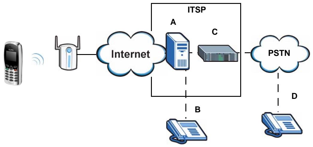
Figure 1 Internet Telephony Service Provider Application
1.1.2 Making Calls via IP-PBX
If your company has an IP-PBX (Internet Protocol Private Branch Exchange), you can use the V630 to make and receive VoIP telephone calls through it.
In this example, you make a call from your V630, which sends it to the IP-PBX. The IP-PBX forwards calls to IP phones through an IP network (the IP phones could also be on the company network or connected to the Internet). The IP-PBX also forwards calls to PSTN phones.
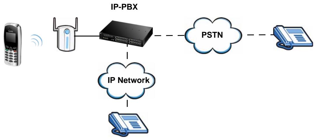
Figure 2 IP-PBX Application
1.1.3 Making Peer to Peer Calls
Use the V630 to make a call to the recipient's IP address without using a SIP server. Peer-to-peer calls are also called "P2P", "Point to Point", or "IP-to-IP" calls. You must know the peer's IP address in order to do this.
The following figure shows a basic example of how you would make a peer-to-peer VoIP call. You make a call on your V630, which sends your call through your Internet connection to the peer VoIP device.

Figure 3 Peer-to-peer Calling
1.2 Ways to Manage the V630
Use any of the following methods to manage the V630.
- Hardware keys. Use the control keys and LCD menus on the V630 for basic configuration. Refer to the Quick Start Guide for descriptions of the hardware features and how to perform basic phone functions.
- Web Configurator. Use this to upload firmware to the V630 using a (supported) web browser.
1.3 Good Habits for Managing the V630
Do the following things regularly to make the V630 more secure and to manage the V630 more effectively.
- Change the web configurator password. Use a password that's not easy to guess and that consists of different types of characters, such as numbers and letters.
- Write down the password and put it in a safe place.
- Keep the V630 in a safe place. The LCD menus are not password-protected, so anyone using the phone can access your phonebook, SIP account information, and so on.
PART II LCD Screen Menus
Using the LCD Screen (35)
Call Log LCD Menus (41)
Profiles LCD Menus (43)
General Setup LCD Menus (49)
Network LCD Menus (69)
The Phonebook (97)
Call Options (107)
Using the LCD Screen
This chapter shows how to use and configure the V630 via the LCD screen menu system.

See the Quick Start Guide for a basic introduction to the LCD screen.
2.1 Entering the Menu System
From the V630's main screen, press the Left key (Menu) to enter the menus. The Main Menu screen displays as shown below.
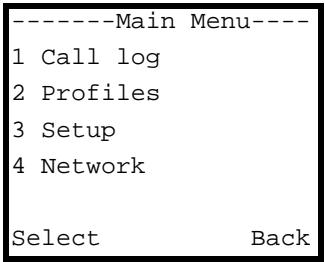
Figure 4 Main Menu
See the following chapters for details on configuring each menu.
2.2 Navigation
Use the following keys to move around the V630's LCD screen menu system.
- The Up and Down keys
Use this to move the cursor up and down (when selecting a menu item) or left and right (when editing a field). - An asterisk (*) next to a menu item identifies the currently configured option.
- The Left and Right keys
Look at the LCD screen. If there is a word or symbol above a softmax, press the key to perform the function.
- The alphanumeric keypad
Enter a menu item's number to jump to that item (single-digit numbers only).
2.3 Entering Numbers, Letters and Symbols
When you enter information into the V630 (when setting up a phonebook entry, for example) you may need to enter different kinds of characters. The alphanumeric keypad has these input modes:
- Lowercase mode
Uppercase mode
Use the # key to cycle between modes.

Not all modes are available in all screens.
When you press a key to enter a character, wait a short time until the cursor moves on to the next space. Press a key multiple times to access the different characters. For example, in Uppercase mode press 9 four times to enter “Z”.
The following tables show the numbers, letters and symbols you can enter in each mode.
Table 2 Lowercase Mode Keypad Characters
| Character Entered for Each Number of Key Presses | ||||||||||||||
| 1 | 2 | 3 | 4 | 5 | 6 | 7 | 8 | 9 | 10 | 11 | 12 | 13 | ||
| EX | 1 | . | , | ' | ? | ! | - | & | # | 1 | _ | € | ||
| 2 | a | b | c | 2 | à | á | ã | ã | ä | à | ç | |||
| 3 | d | e | f | 3 | è | é | ê | ë | ||||||
| 4 | g | h | i | 4 | ì | í | í | ì | ||||||
| 5 | j | k | l | 5 | £ | |||||||||
| 6 | m | n | o | 6 | ñ | ò | ó | ô | ō | ö | ø | |||
| 7 | p | q | r | s | 7 | β | $ | |||||||
| 8 | t | u | v | 8 | ù | ú | ú | ü | ||||||
| 9 | w | x | y | z | 9 | ý | ||||||||
| * | * | @ | ||||||||||||
| 0 | 0,+ | space | ||||||||||||
| # | [CYCLE MODE] | |||||||||||||
Table 3 Uppercase Mode Keypad Characters
| Character Entered for Each Number of Key Presses | ||||||||||||||
| 1 | 2 | 3 | 4 | 5 | 6 | 7 | 8 | 9 | 10 | 11 | 12 | 13 | ||
| EX | 1 | . | , | ' | ? | ! | - | & | # | 1 | _ | € | ||
| 2 | A | B | C | 2 | À | Á | À | À | À | À | Ç | |||
| 3 | D | E | F | 3 | È | É | Ê | Ê | ||||||
| 4 | G | H | I | 4 | ì | í | ì | ì | ||||||
| 5 | J | K | L | 5 | £ | |||||||||
| 6 | M | N | O | 6 | Ñ | Ó | Ó | Ó | Ö | Ö | Ø | |||
| 7 | P | Q | R | S | 7 | $ | ||||||||
| 8 | T | U | V | 8 | ù | ú | Û | Ü | ||||||
| 9 | W | X | Y | Z | 9 | ý | ||||||||
| * | * | @ | ||||||||||||
| 0 | 0,+ | space | ||||||||||||
| # | [CYCLE MODE] | |||||||||||||
2.4 LCD Menu Overview
This section shows the main LCD menus, and describes what you can do with each.
Table 4 LCD Main Menu Overview
| MENU | DESCRIPTION | ||
| Call Log | Missed Calls | Use this menu to list the originating numbers of unanswered calls. | |
| Received Calls | Use this menu to list the originating numbers of answered calls. | ||
| Dialed Calls | Use this menu to list the numbers the V630 has called. | ||
| Delete all | Use this menu to clear all the records in the call log. | ||
| MENU | DESCRIPTION | ||
| Profiles | Normal | Activate | Select this phone profile to use regular tone, volume, and ring settings. |
| Personalize | Use this menu to customize the normal profile's tone, volume, and ring settings. | ||
| Meeting | Activate | Select this phone profile for more discrete tone, volume, and ring settings. | |
| Personalize | Use this menu to customize the meeting profile's tone, volume, and ring settings. | ||
| Outdoor | Activate | Select this phone profile for louder tone, volume, and ring settings. | |
| Personalize | Use this menu to customize the outdoor profile's tone, volume, and ring settings. | ||
| Add to Profile | Use this menu to create a new profile of tone, volume, and ring settings. | ||
| Setup | DateTime | Set Time/Date | Manually set the time and date. |
| Auto Clock Sync. | Set whether or not the V630 gets the time from an NTP time server. When you enable this, specify the server's address. | ||
| Set Time Zone | Set the V630 to the local time zone. | ||
| Phone Setting | Language | Select the menu display language. | |
| Phone lock | Enable or disable the keypad locking function or set the keypad lock to turn on automatically if you do not use the V630 for a specific time. | ||
| Backlight | Set how long the backlight stays on after you stop pressing the V630's keys. You can also set it to be always on or off. | ||
| Quick Button | Set the functions of the Up and Down keys in the main screen. | ||
| Web Config | Turn web configurator access on or off. | ||
| FW Upgrade | Upgrade firmware from an HTTP server. Specify the server's IP address and port number. | ||
| Restore factory | Reset the V630 to the factory default settings. | ||
| Call Setting | Forward | Use this to configure call forwarding. | |
| Send Caller ID | Set whether or not the V630 sends its phone number to the callee. | ||
| Information | TCP/IP | Check the V630's IP settings. | |
| WLAN | Check the V630's wireless LAN settings. | ||
| SIP | Check the V630's VoIP settings. | ||
| HW | Check the V630's free storage space, firmware, and MAC address. | ||
| Log | Check V630's system events log. | ||
| Network | Site scan | Looks for available Access Points (APs). | |
| WLAN Profiles | Profiles List | Look through and edit already configured profiles of WLAN settings. | |
| Add to Profile | Create a profile of WLAN settings. | ||
| SIP Profiles | Profiles List | Look through and edit already configured profiles of SIP settings. | |
| Add to Profile | Create a profile of SIP settings. | ||
| Ping test | Manual | Specify an IP address to which to send a ping. | |
| Gateway | Send a ping to the gateway IP address. | ||
| DNS | Send a ping to the DNS server IP address. | ||
| SIP Server | Send a ping to the SIP server. | ||
| SIP Proxy | Send a ping to the SIP proxy server. | ||
| Outbound Proxy | Send a ping to the SIP outbound proxy server. | ||
| Stun Server | Send a ping to the STUN server. | ||
| Re-connect | Have the V630 attempt to connect to the WLAN. | ||
This section describes the phonebook LCD menus which you access by pressing the Right key from the main screen.
Table 5 LCD Phonebook Menus Overview
| MENU | DESCRIPTION | ||
| Phonebook | Talk | Call the selected contact. | |
| Detail | Display the information configured for the selected contact. | ||
| Edit | Use this to modify the information configured for the selected contact. | ||
| Delete | Remove the selected contact. | ||
| Add | Create a new contact entry. | ||
| Group | None | Select this to not add the contact to any group. | |
| Business | Add members to this group and specify the ring tone for incoming calls coming from them. | ||
| Family | Add members to this group and specify the ring tone for incoming calls coming from them. | ||
| Friends | Add members to this group and specify the ring tone for incoming calls coming from them. | ||
| VIP | Add members to this group and specify the ring tone for incoming calls coming from them. | ||
| Other | Add members to this group and specify the ring tone for incoming calls coming from them. | ||
| Speed Dial | Set up one-touch calling for phone numbers you call often. | ||
| Delete All | Remove all phone book entries. | ||
| Memory Status | This shows how many more phone book entries the V630 can store. | ||
Call Log LCD Menus
This chapter discusses the V630's Call Log LCD menus.
3.1 Call Log
The Call Log menu allows you to quickly check the numbers of the most recent missed, received, or dialed calls. Press Menu > Call Log to display the following screen.
Figure 5 Menu > Call log
-----Call log----
1 Missed Calls
2 Received Calls
3 Dialed Calls
4 Delete all
Select Back
The following table describes the labels in this screen.
Table 6 Menu > Call log
| LABEL | DESCRIPTION |
| Missed Calls | Use this menu to list the originating numbers of unanswered calls. |
| Received Calls | Use this menu to list the originating numbers of answered calls. |
| Dialed Calls | Use this menu to list the numbers the V630 has called. |
| Delete all | Use this menu to clear all the records in the call log. |
| Select | Press this to choose the highlighted field in the menu. |
| Back | Press this to return to the previous screen. |
3.2 Received Calls
The Received Calls menu allows you to quickly check the numbers of the most recent received calls. Press Menu > Call Log > Received Calls to display the following screen. The missed calls and dialed calls lists work in the same manner.
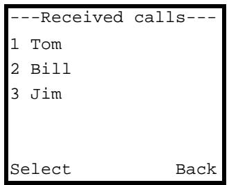
Figure 6 Menu > Call log > Received Calls
The following table describes the labels in this screen.
Table 7 Menu > Call log > Received Calls
| LABEL | DESCRIPTION |
| Received Calls | Select an entry to see the time and date of the call. |
| Select | Press this to choose the highlighted field in the menu. |
| Back | Press this to return to the previous screen. |
Profiles LCD Menus
This chapter discusses the V630's Profiles LCD menus.
4.1 Profiles Setup
Use the Profiles menu to select or modify a profile of tone, volume, and ring settings. Press Menu > Profiles to display the following screen.
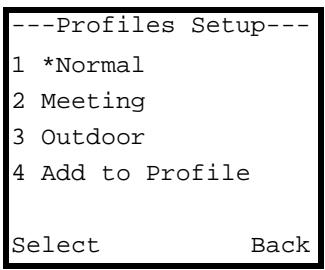
Figure 7 Menu > Profiles
The following table describes the labels in this screen.
Table 8 Menu > Profiles
| LABEL | DESCRIPTION |
| Normal | Use this menu to turn on the normal profile and/or configure the normal profile's tone, volume, and ring settings. |
| Meeting | The meeting profile provides more discrete tone, volume, and ring settings. Use this menu to turn on the meeting profile and/or configure the meeting profile's tone, volume, and ring settings. |
| Outdoor | The outdoors profile has louder tone, volume, and ring settings. Use this menu to turn on the outdoors profile and/or configure the outdoors profile's tone, volume, and ring settings. |
| Add to Profile | Use this menu to create a new profile of tone, volume, and ring settings. |
| Select | Press this to choose the highlighted field in the menu. |
| Back | Press this to return to the previous screen. |
4.2 Phone Profile Options
Press Menu > Profiles to display the profiles. Select a profile to open the following menu. A user-added profile named TEST is shown in this example). You can turn on the profile or configure its settings. You can also rename or delete a user-added profile.

Figure 8 Menu > Profiles > Profile
The following table describes the labels in this screen.
Table 9 Menu > Profiles > Profile
| LABEL | DESCRIPTION |
| Activate | Select this to have the V630 use the profile's tone, volume, and ring settings.Note: There is also a quick button shortcut. Hold down the * key to switch between the current profile and the meeting profile. |
| Personalize | Select this to configure the profile's tone, volume, and ring settings. |
| Rename | Select this to change the name of the profile. This option only appears for profiles that you add. It does not appear with the default profiles. |
| Delete | Select this to remove the profile. This option only appears for profiles that you add. It does not appear with the default profiles. |
| Select | Press this to choose the highlighted field in the menu. |
| Back | Press this to return to the previous screen. |
4.3 Phone Profile Personalization
Press Menu > Profiles to display the profiles. Select a profile (Meeting in this example) and then select Personalize to open the following menu. Select whether you want to edit the profile's tone, volume, or ring settings.
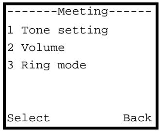
Figure 9 Menu > Profiles > Profile > Personalize
The following table describes the labels in this screen.
Table 10 Menu > Profiles > Profile > Personalize
| LABEL | DESCRIPTION |
| Tone setting | Select this to configure the profile's ring and/or key tone settings. |
| Volume | Select this to configure the profile's ring, receiver, speaker, and/or key tone volume settings. |
| Ring mode | Select this to set the profile to have the V630 ring, vibrate, ring and vibrate, or vibrate and then ring for incoming calls. |
Table 10 Menu > Profiles > Profile > Personalize
| LABEL | DESCRIPTION |
| Select | Press this to choose the highlighted field in the menu. |
| Back | Press this to return to the previous screen. |
4.4 Tone Personalization
Press Menu > Profiles to display the profiles. Select a profile (Meeting in this example) and then select Personalize > Tone setting to open the following menu. Select whether you want to edit the profile's ring tone or key tone settings.
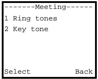
Figure 10 Menu > Profiles > Profile > Personalize > Tone Setting
The following table describes the labels in this screen.
Table 11 Menu > Profiles > Profile > Personalize > Tone Setting
| LABEL | DESCRIPTION |
| Ring tones | Select this to chose the ring tone for incoming calls. |
| Key tone | Select this to turn the key tone (sounds when you press the keys) on or off. |
| Select | Press this to choose the highlighted field in the menu. |
| Back | Press this to return to the previous screen. |
4.5 Ring Tone Personalization
Press Menu > Profiles to display the profiles. Select a profile (Meeting in this example) and then select Personalize > Tone setting > Ring tones to open the following menu. Use this to select the profile's ring tone.
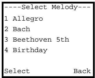
Figure 11 Menu > Profiles > Profile > Personalize > Tone Setting > Ring tones
The following table describes the labels in this screen.
Table 12 Menu > Profiles > Profile > Personalize > Tone Setting > Ring tones
| LABEL | DESCRIPTION |
| Select Melody | Select the ring tone for incoming calls. Leave the cursor on a ring tone for a preview of the tone. The V630's current phone profile must be set to use an audible ring for incoming calls in order for you to here the preview. |
| Select | Press this to choose the highlighted field in the menu. |
| Back | Press this to return to the previous screen. |
4.6 Volume Personalization
Press Menu > Profiles to display the profiles. Select a profile (Meeting in this example) and then select Personalize > Volume to open the following menu. You can modify the profile's ring, receiver, speaker, and/or key tone volume settings.
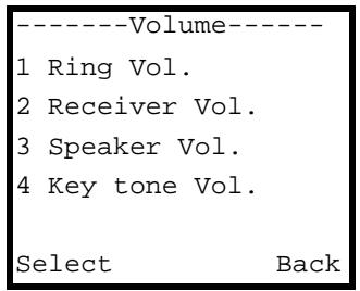
Figure 12 Menu > Profiles > Profile > Personalize > Volume
The following table describes the labels in this screen.
Table 13 Menu > Profiles > Profile > Personalize > Volume
| LABEL | DESCRIPTION |
| Ring Vol. | Select this to set how loud the ring tone for incoming calls is. |
| Receiver Vol. | Select this to set how loud your voice sounds to the person you are talking to. |
| Speaker Vol. | Select this to set the volume of the V630's speaker (how loud the voice of the person you are talking to sounds). |
| Key tone Vol. | Select this to set the key tone volume (how load the sounds are when you press the keys). |
| Select | Press this to choose the highlighted field in the menu. |
| Back | Press this to return to the previous screen. |
4.7 Ring Volume Personalization
Press Menu > Profiles to display the profiles. Select a profile (Meeting in this example) and then select Personalize > Volume. When you select an option in the Volume menu, a screen similar to the following displays. This example uses the Ring Vol. screen.
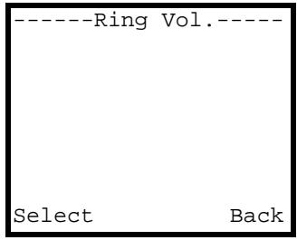
Figure 13 Menu > Profiles > Profile > Personalize > Volume > Ring Vol.
The following table describes the labels in this screen.
Table 14 Menu > Profiles > Profile > Personalize > Volume > Ring Vol.
| LABEL | DESCRIPTION |
| Ring Vol. | The bar in the screen displays the volume setting. Use the numbers on the keypad to set the volume higher or lower. |
| Back | Press this to return to the previous screen. |
4.8 Ring Mode Personalization
Press Menu > Profiles to display the profiles. Select a profile (Meeting in this example) and then select Personalize > Ring Mode to open the following menu. You can set the profile to have the V630 ring, vibrate, ring and vibrate, or vibrate and then ring for incoming calls.
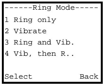
Figure 14 Menu > Profiles > Profile > Personalize > Ring Mode
The following table describes the labels in this screen.
Table 15 Menu > Profiles > Profile > Personalize > Ring Mode
| LABEL | DESCRIPTION |
| Ring only | Select this to have the phone only ring for incoming calls (not vibrate). |
| Vibrate | Select this to have the phone only vibrate for incoming calls (not ring). |
| Ring and Vib. | Select this to have the phone ring and vibrate for incoming calls. |
| Vib, then Ring | Select this to have the phone vibrate first for an incoming call and then ring if you haven’t answered it yet. |
| Select | Press this to choose the highlighted field in the menu. |
| Back | Press this to return to the previous screen. |
4.9 Adding a Phone Profile
Press Menu > Profiles to display the profiles. Select Add to Profile to open the following menu. Use this menu to configure the name of the new profile. Then you can use the menus to configure the profile in the same way that you configure an existing profile.
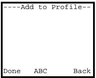
Figure 15 Menu > Profiles > Add to Profile
The following table describes the labels in this screen.
Table 16 Menu > Profiles > Add to Profile
| LABEL | DESCRIPTION |
| Input the name of the profile. When you press a key, other character options appear above the input field. Press a key multiple times to input one of the characters above. | |
| Done | Press this to save your setting. |
| ABC | Press # to switch between the lower-case and upper-case input modes. |
| Back | Press this to return to the previous screen. |
| Clear | After you start inputting text, Back changes to Clear. Press this to backspace. |
General Setup LCD Menus
This chapter discusses the V630's Setup LCD menus.
5.1 General Setup
Use the Setup menu to configure the V630's general settings and display various types of status information. Press Menu > Setup to display the following screen.
Figure 16 Menu > Setup
----Setup----
1 DateTime
2 Phone Setting
3 Call Setting
4 Information
Select Back
The following table describes the labels in this screen.
Table 17 Menu > Setup
| LABEL | DESCRIPTION |
| DateTime | Select this to configure the V630's time and date settings. |
| Phone Setting | Select this to configure the V630's general phone settings such as the display language, keypad lock, backlight, quick access buttons, and web configurator access. You can also upgrade the V630's firmware or reset the V630 to the factory default settings. |
| Call Setting | Select this to configure call forwarding and whether or not the V630 sends its phone number to the callee. |
| Information | Select this to check the V630's IP, wireless LAN, and VoIP settings. You can also display the V630's free storage space, firmware, MAC address, and system events log. |
| Select | Press this to choose the highlighted field in the menu. |
| Back | Press this to return to the previous screen. |
5.2 Date and Time Setup
Press Menu > Setup > DateTime to display the following screen. Use this menu to select what time and date settings you want to configure.
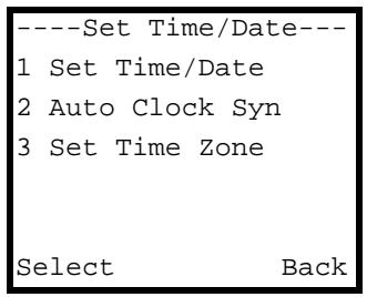
Figure 17 Menu > Setup > DateTime
The following table describes the labels in this screen.
Table 18 Menu > Setup > DateTime
| LABEL | DESCRIPTION |
| Set Time/Date | Select this to manually set the time and date. |
| Auto Clock Sync. | Select this to set whether or not the V630 gets the time from an NTP time server. When you enable this, specify the server's address. |
| Set Time Zone | Select this to set the V630 to the local time zone. |
| Select | Press this to choose the highlighted field in the menu. |
| Back | Press this to return to the previous screen. |
5.3 Manual Date or Time Setup
Press Menu > Setup > DateTime > Set Time/Date to display the following screen. Use this menu to select whether to want to manually set the time or the date.
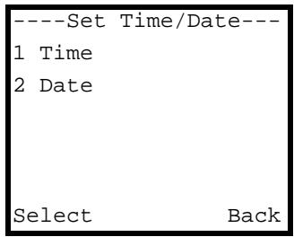
Figure 18 Menu > Setup > DateTime > Set Time/Date
The following table describes the labels in this screen.
Table 19 Menu > Setup > DateTime > Set Time/Date
| LABEL | DESCRIPTION |
| Time | Select this to manually set the time. |
| Date | Select this to manually set the date. |
| Select | Press this to choose the highlighted field in the menu. |
| Back | Press this to return to the previous screen. |
5.4 Manual Time Setup
Press Menu > Setup > DateTime > Set Time/Date > Time to display the following screen. Use this menu to select whether to manually set the time.
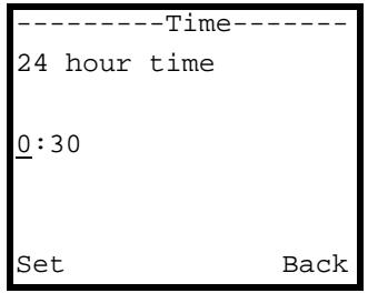
Figure 19 Menu > Setup > DateTime > Set Time/Date > Time
The following table describes the labels in this screen.
Table 20 Menu > Setup > DateTime > Set Time/Date > Time
| LABEL | DESCRIPTION |
| 24 hour time | Use the numbers on the keypad to set the hour (in 24-hour format) and then the minute. Use the Up and Down keys if you need to move the cursor. |
| Set | Press this to enter your setting. |
| Back | Press this to return to the previous screen. |
5.5 Manual Date Setup
Press Menu > Setup > DateTime > Set Time/Date > Date to display the following screen. Use this menu to select whether to manually set the date.
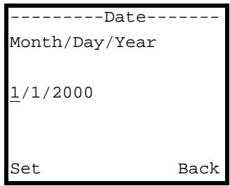
Figure 20 Menu > Setup > DateTime > Set Time/Date > Date
The following table describes the labels in this screen.
Table 21 Menu > Setup > DateTime > Set Time/Date > Date
| LABEL | DESCRIPTION |
| Month/Day/Year | Use the numbers on the keypad to set the month, day, and year. Use the Up and Down keys if you need to move the cursor. |
| Set | Press this to enter your setting. |
| Back | Press this to return to the previous screen. |
5.6 Using a Time Server
Press Menu > Setup > DateTime > Auto Clock Syn to display the following screen. Use this menu to set whether or not the V630 uses a time server.

The V630 has to be able to connect to the Internet to actually get the time and date from a time server.
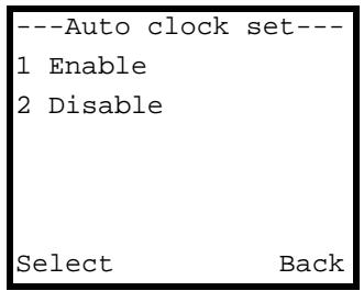
Figure 21 Menu > Setup > DateTime > Auto Clock Syn
The following table describes the labels in this screen.
Table 22 Menu > Setup > DateTime > Auto Clock Syn
| LABEL | DESCRIPTION |
| Enable | Select this to have the V630 attempt to get the time from an NTP time server. |
| Date | Select this to stop the V630 from attempting to get the time from an NTP time server. |
| Select | Press this to choose the highlighted field in the menu. |
| Back | Press this to return to the previous screen. |
5.7 Specifying a Time Server
Press Menu > Setup > DateTime > Auto Clock Syn > Enable to display the following screen. Use this menu to specify a time server for the V630 to use.
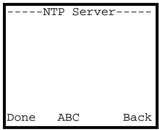
Figure 22 Menu > Setup > DateTime > Auto Clock Syn > Enable
The following table describes the labels in this screen.
Table 23 Menu > Setup > DateTime > Auto Clock Syn > Enable
| LABEL | DESCRIPTION |
| NTP Server | Input the IP address or URL of the NTP time server. When you press a key, other character options appear above the input field. Press a key multiple times to input one of the characters above. |
| Done | Press this to save your setting. |
| ABC | Press # to switch between the lower-case and upper-case input modes. |
| Back | Press this to return to the previous screen. |
| Clear | After you start inputting text, Back changes to Clear. Press this to backspace. |
5.8 Time Zone Setup
Press Menu > Setup > DateTime > Set Time Zone to display the following screen. Use this menu to set the V630 to use the local time zone.
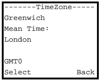
Figure 23 Menu > Setup > DateTime > Time Zone
The following table describes the labels in this screen.
Table 24 Menu > Setup > DateTime > Time Zone
| LABEL | DESCRIPTION |
| Time Zone | Use the Up or Down to your local time zone. |
| GMT0 | This shows how many hours the time zone is ahead of or behind GMT (Greenwich Mean Time). |
| Select | Press this to choose the highlighted field in the menu. |
| Back | Press this to return to the previous screen. |
5.9 General Phone Setup
Press Menu > Setup > Phone Setting to display the following screen. Use this menu to select which of the V630's general phone settings to configure. You can set the display language, keypad lock, backlight, quick access buttons, and web configurator access. You can also upgrade the V630's firmware or reset the V630 to the factory default settings.
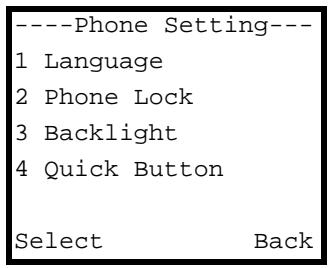
Figure 24 Menu > Setup > Phone Setting
The following table describes the labels in this screen.
Table 25 Menu > Setup > Phone Setting
| LABEL | DESCRIPTION |
| Language | Select the menu display language. |
| Phone lock | Enable or disable the automatic keypad locking function or set the keypad lock to turn on automatically if you do not use the V630 for a specific time. |
| Backlight | Set how long the backlight stays on after you stop pressing the V630's keys. You can also set it to be always on or off. |
| Quick Button | Set the functions of the Up and Down keys in the main screen. |
| Web Config | Turn web configurator access on or off. |
| FW Upgrade | Upgrade firmware from an HTTP server. Specify the server's IP address and port number. |
| Restore factory | Reset the V630 to the factory default settings. |
| Select | Press this to choose the highlighted field in the menu. |
| Back | Press this to return to the previous screen. |
5.10 Language Setup
Press Menu > Setup > Phone Setting > Language to display the following screen. Use this menu to select the V630's display language.1
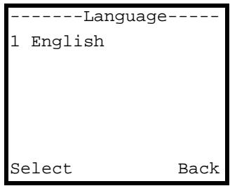
Figure 25 Menu > Setup > Phone Setting > Language
The following table describes the labels in this screen.
Table 26 Menu > Setup > Phone Setting > Language
| LABEL | DESCRIPTION |
| Language | Select the menu display language. |
- Only English is supported at the time of writing.
Table 26 Menu > Setup > Phone Setting > Language
| LABEL | DESCRIPTION |
| Select | Press this to choose the highlighted field in the menu. |
| Back | Press this to return to the previous screen. |
5.11 Keypad Lock Setup
Press Menu > Setup > Phone Setting > Phone lock to display the following screen. The V630's keypad lock helps prevent accidental calls. Use this menu to set the V630's automatic keypad lock.

Regardless of the setting in this menu, you can still press the Left key and * from the main screen to lock or unlock the V630's keypad.
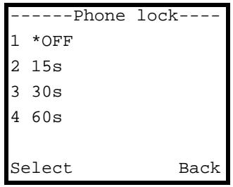
Figure 26 Menu > Setup > Phone Setting > Phone lock
The following table describes the labels in this screen.
Table 27 Menu > Setup > Phone Setting > Phone lock
| LABEL | DESCRIPTION |
| Phone lock | Select OFF to turn off the automatic keypad lock function (to always leave the keypad unlocked). Or select the number of idle seconds after which the V630 automatically locks the keypad. For example, select 30s to have the V630 lock the keypad after you stop using the V630 for longer than 30 seconds. |
| Select | Press this to choose the highlighted field in the menu. |
| Back | Press this to return to the previous screen. |
5.12 Backlight Setup
Press Menu > Setup > Phone Setting > Backlight to display the following screen. Use this menu to set how long the V630's backlight stays on.
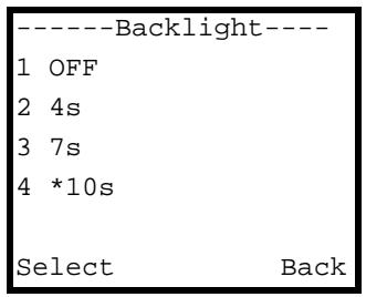
Figure 27 Menu > Setup > Phone Setting > Backlight
The following table describes the labels in this screen.
Table 28 Menu > Setup > Phone Setting > Backlight
| LABEL | DESCRIPTION |
| Phone lock | Select OFF to turn off the backlight all the time. Or select the number of idle seconds after which the V630 automatically turns off the backlight. For example, select 10s to have the V630 turn off the backlight 10 seconds after you stop pressing the keys. |
| Select | Press this to choose the highlighted field in the menu. |
| Back | Press this to return to the previous screen. |
5.13 Quick Button Setup
Press Menu > Setup > Phone Setting > Quick button to display the following screen. Use this menu to select which quick access button you want to configure.
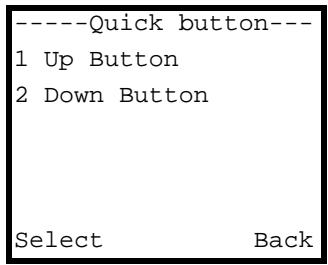
Figure 28 Menu > Setup > Phone Setting > Quick button
The following table describes the labels in this screen.
Table 29 Menu > Setup > Phone Setting > Quick button
| LABEL | DESCRIPTION |
| Up Button | Select this to configure the function of the Up key in the main screen. |
| Down Button | Select this to configure the function of the Down key in the main screen. |
| Select | Press this to choose the highlighted field in the menu. |
| Back | Press this to return to the previous screen. |
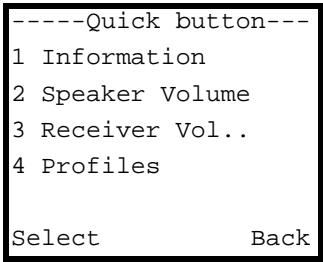
5.14 Up Quick Button Setup
Press Menu > Setup > Phone Setting > Quick button > Up Button to display the following screen. Use this menu to configure the function of the Up key in the main screen. The configuration for the Down key works in the same manner.
Figure 29 Menu > Setup > Phone Setting > Quick button > Up Button
The following table describes the labels in this screen.
Table 30 Menu > Setup > Phone Setting > Quick button > Up Button
| LABEL | DESCRIPTION |
| Information | |
| Speaker Volume | Select this to open the talking volume setting when you press the Up key in the main screen. |
| Receiver Volume | Select this to open the listening volume setting when you press the Up key in the main screen. |
| Profiles | Select this to be able to select or configure phone profiles when you press the Up key in the main screen. |
| Select | Press this to choose the highlighted field in the menu. |
| Back | Press this to return to the previous screen. |
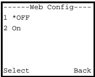
5.15 Enabling or Disabling the Web Configurator
Press Menu > Setup > Phone Setting > Web Config to display the following screen. Use this menu to turn web configurator access on or off.
Figure 30 Menu > Setup > Phone Setting > Web Config
The following table describes the labels in this screen.
Table 31 Menu > Setup > Phone Setting > Web Config
| LABEL | DESCRIPTION |
| OFF | Select this to not allow access to the web configurator. |
| ON | Select this to allow access to the web configurator.Note:Allowing access to the web configurator reduces battery life. |
| Select | Press this to choose the highlighted field in the menu. |
| Back | Press this to return to the previous screen. |
5.16 Firmware Upgrade from an HTTP Server
Press Menu > Setup > Phone Setting > FW Upgrade to display the following screen. Use this menu to select whether you want to upgrade firmware from an HTTP server, specify the server's address, or specify the server's port number.

Your network administrator or service provider must have an HTTP server set up with the firmware file in order for you to use this.
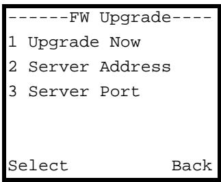
Figure 31 Menu > Setup > Phone Setting > FW Upgrade
The following table describes the labels in this screen.
Table 32 Menu > Setup > Phone Setting > FW Upgrade
| LABEL | DESCRIPTION |
| Upgrade Now | Select this to upload new firmware from the HTTP server. You need to have the server's address and port number configured already to be able to use this. |
| Server Address | Select this to go to a menu where you can enter the address of the HTTP server. |
| Server Port | Select this to go to a menu where you can enter the port number of the HTTP server. You need to do this if the HTTP server with the firmware is not using the standard port number (80). |
| Select | Press this to choose the highlighted field in the menu. |
| Back | Press this to return to the previous screen. |
5.17 HTTP Firmware Upgrade Server Address
Press Menu > Setup > Phone Setting > FW Upgrade > Server Address to display the following screen. Use this menu to specify the server's address. The port configuration menu works in a similar manner, except you can only input numbers.
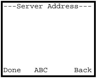
Figure 32 Menu > Setup > Phone Setting > FW Upgrade > Server Address
The following table describes the labels in this screen.
Table 33 Menu > Setup > Phone Setting > FW Upgrade > Server Address
| LABEL | DESCRIPTION |
| Server Address | Input the IP address or URL of the HTTP server with the firmware file. When you press a key, other character options appear above the input field. Press a key multiple times to input one of the characters above. |
| Done | Press this to save your setting. |
| ABC | Press # to switch between the lower-case and upper-case input modes. |
| Back | Press this to return to the previous screen. |
| Clear | After you start inputting text, Back changes to Clear. Press this to backspace. |
5.18 Restore Factory Default Settings
Press Menu > Setup > Phone Setting > Restore Factory to display the following screen. Use this menu to reset the V630 to the factory default settings.

Restoring the factory default settings resets all of the phone's settings except your phone book entries.

Figure 33 Menu > Setup > Phone Setting > Restore Factory
The following table describes the labels in this screen.
Table 34 Menu > Setup > Phone Setting > Restore Factory
| LABEL | DESCRIPTION |
| Yes | Select this to reset the V630 to the factory default settings. |
| Cancel | Select this to return to the previous screen without resetting the V630 to the factory default settings. |
5.19 Call Settings
Press Menu > Setup > Call Setting to display the following screen. Use this menu to go to menus where you can configure call forwarding or whether or not the V630 sends its phone number to the callee.
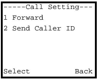
Figure 34 Menu > Setup > Call Setting
The following table describes the labels in this screen.
Table 35 Menu > Setup > Call Setting
| LABEL | DESCRIPTION |
| Forward | Use this to configure call forwarding. |
| Send Caller ID | Set whether or not the V630 sends its phone number to the callee. |
| Select | Press this to choose the highlighted field in the menu. |
| Back | Press this to return to the previous screen. |
5.20 Call Forwarding
Press Menu > Setup > Call Setting > Forward to display the following screen. Use this menu to turn call forwarding on or off.
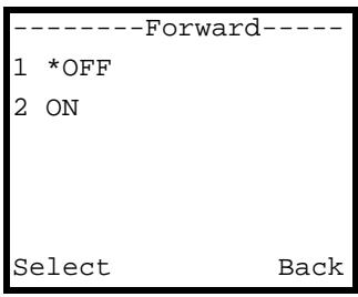
Figure 35 Menu > Setup > Call Setting > Forward
The following table describes the labels in this screen.
Table 36 Menu > Setup > Call Setting > Forward
| LABEL | DESCRIPTION |
| OFF | Select this to not forward calls. |
| ON | Select this to forward calls. |
| Select | Press this to choose the highlighted field in the menu. |
| Back | Press this to return to the previous screen. |
5.21 Call Forwarding Number
Press Menu > Setup > Call Setting > Forward > ON to display the following screen. Use this menu to input the phone number to which you want to forward calls.

Figure 36 Menu > Setup > Call Setting > Forward > ON
The following table describes the labels in this screen.
Table 37 Menu > Setup > Call Setting > Forward > ON
| LABEL | DESCRIPTION |
| Forward Number | Use the number keys to input the phone number to which you want to forward calls. |
| Done | Press this to save your setting. |
| Back | Press this to return to the previous screen. |
| Clear | After you start inputting text, Back changes to Clear. Press this to backspace. |
5.22 Call Forwarding Type
Press Menu > Setup > Call Setting > Forward > ON and input a phone number to display the following screen. Use this menu to set under what circumstances you want to apply call forwarding.

Figure 37 Menu > Setup > Call Setting > Forward > ON > Number
The following table describes the labels in this screen.
Table 38 Menu > Setup > Call Setting > Forward > ON > Number
| LABEL | DESCRIPTION |
| Always | Select this to forward all calls to the specified number (regardless of whether or not your line is busy). |
| Busy | Select this to forward calls when your line is busy. |
| No Answer | Select this to forward calls when you do not answer the phone. You will be able to specify how long the V630 waits before forwarding an unanswered call. |
| Busy & No Answer | Select this to forward calls when your line is busy or you do not answer the phone. You will be able to specify how long the V630 waits before forwarding an unanswered call. |
| Select | Press this to choose the highlighted field in the menu. |
| Back | Press this to return to the previous screen. |
5.23 Call Forwarding No Answer Time
When you set the call forwarding type to No Answer or Busy & No Answer, use this menu to specify how long the V630 waits before forwarding an unanswered call.
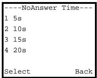
Figure 38 Menu > Setup > Call Setting > Forward > ON > Number > Type > No Answer
The following table describes the labels in this screen.
Table 39 Menu > Setup > Call Setting > Forward > ON > Number > Type > No Answer
| LABEL | DESCRIPTION |
| NoAnswer Time | Specify how long the V630 waits before forwarding an unanswered call. You can use one of the pre-defined settings (5, 10, 15 or 20 seconds) or select Other to manually configure another time period. |
| Busy | Select this to forward calls when your line is busy. |
| Select | Press this to choose the highlighted field in the menu. |
| Back | Press this to return to the previous screen. |
5.24 Call Forwarding No Answer Time
When you set the call forwarding type to No Answer or Busy & No Answer and select Other as the no answer time, use this menu to specify a custom time period for how long the V630 waits before forwarding an unanswered call.
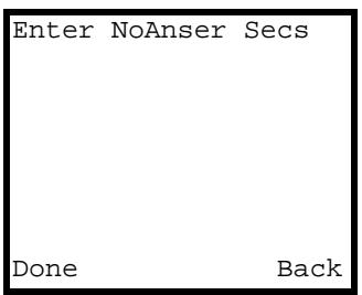
Figure 39 Menu > Setup > Call Setting > Forward > ON > Number > Type > No Answer > Other
The following table describes the labels in this screen.
Table 40 Menu > Setup > Call Setting > Forward > ON > Number > Type > No Answer > Other
| LABEL | DESCRIPTION |
| Enter NoAnser Secs | Use the number keys to input the number of seconds the V630 waits before forwarding an unanswered call |
| Done | Press this to save your setting. |
| Back | Press this to return to the previous screen. |
| Clear | After you start inputting text, Back changes to Clear. Press this to backspace. |
5.25 Send Caller ID
Press Menu > Setup > Call Setting > Send Caller ID to display the following screen. Use this menu to set whether or not the V630 sends your phone number to the phones you call.
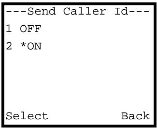
Figure 40 Menu > Setup > Call Setting > Send Caller ID
The following table describes the labels in this screen.
Table 41 Menu > Setup > Call Setting> Send Caller ID
| LABEL | DESCRIPTION |
| OFF | Select this to have the V630 not send your phone number to the phones you call. |
| ON | Select this to have the V630 send your phone number to the phones you call. |
Table 41 Menu > Setup > Call Setting> Send Caller ID
| LABEL | DESCRIPTION |
| Select | Press this to choose the highlighted field in the menu. |
| Back | Press this to return to the previous screen. |
5.26 Information
Press Menu > Setup > Information to display the following screen. Use this menu to go to menus where you can check the V630's IP, wireless LAN, and VoIP settings. You can also display the V630's free storage space, firmware, MAC address, and system events log.
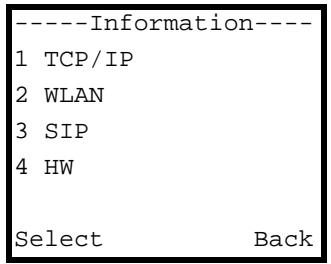
Figure 41 Menu > Setup > Information
The following table describes the labels in this screen.
Table 42 Menu > Setup > Information
| LABEL | DESCRIPTION |
| TCP/IP | Select this to check the V630's IP settings. |
| WLAN | Select this to check the V630's wireless LAN settings. |
| SIP | Select this to check the V630's VoIP settings. |
| HW | Select this to check the V630's free storage space, firmware, and MAC address. |
| Log | Select this to check the V630's system events log. |
| Select | Press this to choose the highlighted field in the menu. |
| Back | Press this to return to the previous screen. |
5.27 TCP/IP Information
Press Menu > Setup > Information > TCP/IP to display the following screen. Use this menu to check the V630's IP address, subnet mask, default gateway IP address, and DNS server IP address. The IP address displays first. Use the Down key to scroll in order to display the other settings.

"Network Not Up Yet!" displays if the V630 has not connected to an AP yet.
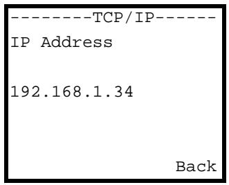
Figure 42 Menu > Setup > Information > TCP/IP
The following table describes the labels in this screen.
Table 43 Menu > Setup > Information > TCP/IP
| LABEL | DESCRIPTION |
| IP Address | This is the IP address currently assigned to the V630. |
| IP Subnet Mask | This is the subnet mask currently configured on the V630. |
| Gateway | This is the IP address of the device on the network that your V630 uses to access other networks (like the Internet). |
| DNS | This is the DNS (Domain Name System) server your V630 uses. |
| Back | Press this to return to the previous screen. |
5.28 WLAN Information
Press Menu > Setup > Information > WLAN to display the following screen. Use this menu to check the V630's wireless LAN settings. The SSID displays first. Use the Down key to scroll in order to display the other settings.
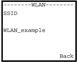
Figure 43 Menu > Setup > Information > WLAN
The following table describes the labels in this screen.
Table 44 Menu > Setup > Information > WLAN
| LABEL | DESCRIPTION |
| SSID | This is theSSID that the V630 is currently using. |
| BSSID | This is the V630's MAC (Media Access Control) address. Every network device has a unique MAC address that identifies it across the network. |
| Channel | This is the radio frequency that the V630 is currently using. |
| Security | This is the type of wireless security that the V630 is currently using. The V630 supports WEP, WPA PSK, WPA2 PSK, WPA, and WPA2. |
| Back | Press this to return to the previous screen. |
5.29 SIP Information
Press Menu > Setup > Information > SIP to display the following screen. Use this menu to check the settings for the SIP account the V630 is currently using. The phone number displays first. Use the Down key to scroll in order to display the other settings.
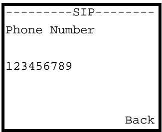
Figure 44 Menu > Setup > Information > SIP
The following table describes the labels in this screen.
Table 45 Menu > Setup > Information > SIP
| LABEL | DESCRIPTION |
| Phone Number | This is the SIP account's phone number. |
| SIP Server | This is the address of the SIP server for the SIP account. |
| SIP Proxy | This is the address of the SIP proxy server for the SIP account. |
| Outbound Proxy | This is the address of the outbound proxy server for the SIP account. |
| Stun Server | This is the address of the STUN server for the SIP account. |
| Expire | This is the SIP server expire time. |
| Back | Press this to return to the previous screen. |
5.30 Hardware Information
Press Menu > Setup > Information > HW to display the following screen. Use this menu to check details about the V630's hardware. The available storage space displays first. Use the Down key to scroll in order to display the other settings.
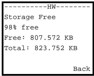
Figure 45 Menu > Setup > Information > HW
The following table describes the labels in this screen.
Table 46 Menu > Setup > Information > HW
| LABEL | DESCRIPTION |
| Storage Free | This shows how much of the V630's storage space is available. |
| FW Version | This is the firmware (embedded software) version and creation date. |
Table 46 Menu > Setup > Information > HW
| LABEL | DESCRIPTION |
| Mac Address | This is the V630's MAC (Media Access Control) address. Every network device has a unique MAC address that identifies it across the network. |
| Back | Press this to return to the previous screen. |
5.31 Log Information
Press Menu > Setup > Information > Log to display the following screen. Use this menu to check the V630's system events log. Use the Down key to scroll through the log entries.
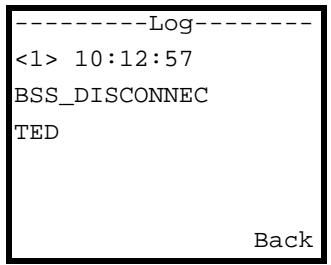
Figure 46 Menu > Setup > Information > Log
The following table describes the labels in this screen.
Table 47 Menu > Setup > Information > Log
| LABEL | DESCRIPTION |
| <1> | This is the log entry's index number. |
| Time | This is the time that the log was created (in hour:minute:second format). |
| Message | This is the reason for the log. |
| Back | Press this to return to the previous screen. |
Network LCD Menus
This chapter discusses the V630's Network LCD menus.
6.1 Network Setup
Use the Network menu to select or modify a profile of tone, volume, and ring settings. Press Menu > Network to display the following screen.
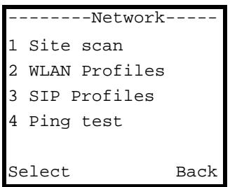
Figure 47 Menu > Network
The following table describes the labels in this screen.
Table 48 Menu > Network
| LABEL | DESCRIPTION |
| Site scan | Use this menu to have the V630 check for available Access Points (APs). |
| WLAN Profiles | Use these menus to edit configured profiles of WLAN settings or add new profiles of WLAN settings. |
| SIP Profiles | Use these menus to add and edit profiles of SIP settings. |
| Ping test | Use this menu to have the V630 send a ping to an IP address to check the network connectivity to a device. |
| Re-connect | Use this menu to have the V630 attempt to connect to the WLAN. |
| Select | Press this to choose the highlighted field in the menu. |
| Back | Press this to return to the previous screen. |
6.2 Site Scan
Press Menu > Network > Site scan to have the V630 check for available APs. After the V630 finishes scanning, use the Down key to scroll to the AP to which you want to connect.
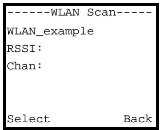
Figure 48 Menu > Network > Site scan
The following table describes the labels in this screen.
Table 49 Menu > Network > Site scan
| LABEL | DESCRIPTION |
| SSID | The wireless network'sSSID (name) displays at the top of the entry. |
| RSSI | This is the RSSI (Received Signal Strength Indicator) of the wireless connection. |
| Chan | This is the radio frequency that the wireless network is using. |
| Select | Press this to choose the highlighted field in the menu. |
| Back | Press this to return to the previous screen. |
6.3 Wireless Security
After you use the site scan and select the AP to which you want to connect, this menu displays if the AP uses security. Use this menu to enter the wireless network's security key (password).
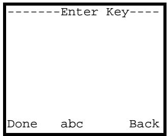
Figure 49 Menu > Network > Site scan > AP
The following table describes the labels in this screen.
Table 50 Menu > Network > Site scan > AP
| LABEL | DESCRIPTION |
| Enter Key | Use the V630's alphanumeric keypad to input the AP's security key (password). When you press a key, other character options appear above the input field. Press a key multiple times to input one of the characters above. |
| Done | Press this to save your setting. The Add to Profile menu appears. Wait a few minutes while the V630 attempts to connect to the AP. The signal strength icon displays after the V630 connects to the AP. See Section 6.7 on page 72 for details on editing WLAN profiles. |
| abc | Press # to switch between the lower-case and upper-case input modes. |
| Back | Press this to go to the WLAN profile's setup menu. |
| Clear | After you start inputting text, Back changes to Clear. Press this to backspace. |
6.4 WLAN Profiles
Press Menu > Network > WLAN Profiles to display the following menu. Use this menu to select whether you want to go to the list of already configured profiles of WLAN settings or create a profile of WLAN settings.
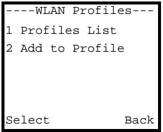
Figure 50 Menu > Network > WLAN Profiles
The following table describes the labels in this screen.
Table 51 Menu > Network > WLAN Profiles
| LABEL | DESCRIPTION |
| Profiles List | Look through and edit already configured profiles of WLAN settings. |
| Add to Profile | Create a profile of WLAN settings. |
| Select | Press this to choose the highlighted field in the menu. |
| Back | Press this to return to the previous screen. |
6.5 WLAN Profiles List
Press Menu > Network > WLAN Profiles > Profiles List to display the following menu. Use this menu to look through and edit already configured profiles of WLAN settings.
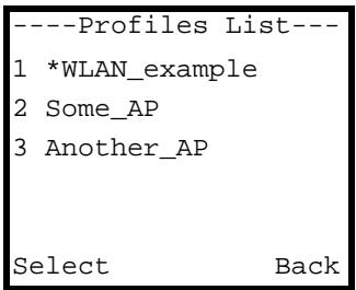
Figure 51 Menu > Network > WLAN Profiles > Profiles List
The following table describes the labels in this screen.
Table 52 Menu > Network > WLAN Profiles > Profiles List
| LABEL | DESCRIPTION |
| Profiles List | These are the already configured profiles of WLAN settings. An asterisk (*) identifies the profile the V630 is currently using. Select a profile to connect to the AP or edit or delete the profile. |
| Select | Press this to choose the highlighted field in the menu. |
| Back | Press this to return to the previous screen. |
6.6 WLAN Profile
Press Menu > Network > WLAN Profiles > Profiles List and select a profile to display the following menu. Use this menu to use the selected profile or delete the selected profile. You can also go to other menus to edit it.
Figure 52 Menu > Network > WLAN Profiles > Profiles List > Profile

The following table describes the labels in this screen.
Table 53 Menu > Network > WLAN Profiles > Profiles List > Profile
| LABEL | DESCRIPTION |
| Connect | Select this to connect to the AP. |
| Edit | Select this to modify the profile. This opens a menu were you can select what you want to modify. See Section 6.7 on page 72 for details on the WLAN profile editing screens. |
| Delete | Select this to remove the profile. |
| Select | Press this to choose the highlighted field in the menu. |
| Back | Press this to return to the previous screen. |
6.7 Adding a WLAN Profile
Press Menu > Network > WLAN Profiles > Add to Profile to display the following menu. Use this menu to create a profile of WLAN settings.
Figure 53 Menu > Network > WLAN Profiles > Add to Profile
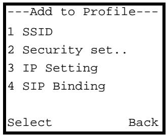
The following table describes the labels in this screen.
Table 54 Menu > Network > WLAN Profiles > Add to Profile
| LABEL | DESCRIPTION |
| SSID | Select this to specify the AP'sSSID (name). |
| Security setting | Select this to specify the type of security the AP uses and the security key (password). |
Table 54 Menu > Network > WLAN Profiles > Add to Profile
| LABEL | DESCRIPTION |
| IP Setting | Select this to set the V630's IP address settings. |
| SIP Binding | Select this to specify the SIP profile to use when connecting to this AP. |
| Select | Press this to choose the highlighted field in the menu. |
| Back | Press this to return to the previous screen. |
6.8 Setting the SSID
Press Menu > Network > WLAN Profiles > Add to Profile > SSID to display the following menu. Use this menu to specify the AP's SSID (name).
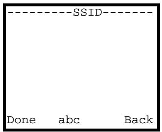
Figure 54 Menu > Network > WLAN Profiles > Add to Profile > SSID
The following table describes the labels in this screen.
Table 55 Menu > Network > WLAN Profiles > Add to Profile > SSID
| LABEL | DESCRIPTION |
| SSID | Use the V630's alphanumeric keypad to input the AP's SSID (name). When you press a key, other character options appear above the input field. Press a key multiple times to input one of the characters above. |
| Done | Press this to save your setting. |
| abc | Press # to switch between the lower-case and upper-case input modes. |
| Back | Press this to go to the WLAN profile's setup menu. |
| Clear | After you start inputting text, Back changes to Clear. Press this to backspace. |
6.9 Setting the Wireless Security Type
Press Menu > Network > WLAN Profiles > Add to Profile > Security setting to display the following menu. Use this menu to specify the type of wireless security the AP uses. An asterisk (*) identifies the profile's currently selected security setting.
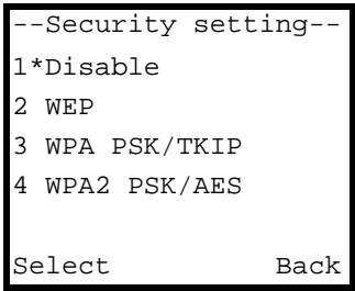
Figure 55 Menu > Network > WLAN Profiles > Add to Profile > Security setting
The following table describes the labels in this screen.
Table 56 Menu > Network > WLAN Profiles > Add to Profile > Security setting
| LABEL | DESCRIPTION |
| Disable | Select this option if the AP does not use wireless security. |
| WEP | Select this option if the AP uses WEP wireless security.Note: WEP is extremely insecure. Its encryption can be broken by an attacker, using widely-available software. It is strongly recommended that you use a more effective security mechanism. Use the strongest security mechanism that all the wireless devices in your network support. For example, use WPA-PSK or WPA2-PSK if all your wireless devices support it, or use WPA or WPA2 if your wireless devices support it and you have a RADIUS server. If your wireless devices support nothing stronger than WEP, use the highest encryption level available. |
| WPA PSK/TKIP | Select this option if the AP uses WPA-PSK wireless security. |
| WPA2 PSK/AES | Select this option if the AP uses WPA2-PSK wireless security. |
| WPA-EAP | Select this option if the AP uses WPA wireless security. |
| WPA2-EAP | Select this option if the AP uses WPA2 wireless security. |
| Select | Press this to choose the highlighted field in the menu. |
| Back | Press this to return to the previous screen. |
6.10 Setting the Wireless Security Key
Press Menu > Network > WLAN Profiles > Add to Profile > Security setting and select a security type to display the following menu. Use this menu to enter the wireless network's security key (password).
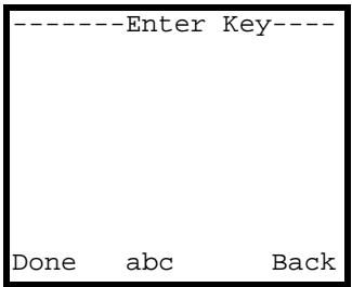
Figure 56 Menu > Network > WLAN Profiles > Add to Profile > Security setting > Security Type
The following table describes the labels in this screen.
Table 57 Menu > Network > WLAN Profiles > Add to Profile > Security setting > Security Type
| LABEL | DESCRIPTION |
| Enter Key | Use the V630's alphanumeric keypad to input the AP's security key (password). When you press a key, other character options appear above the input field. Press a key multiple times to input one of the characters above. |
| Done | Press this to save your setting. |
| abc | Press # to switch between the lower-case and upper-case input modes. |
| Back | Press this to go to the previous menu. |
| Clear | After you start inputting text, Back changes to Clear. Press this to backspace. |
6.11 IP Settings
Press Menu > Network > WLAN Profiles > Add to Profile > IP Setting to display the following menu. Use this menu to modify the V630's IP address settings.
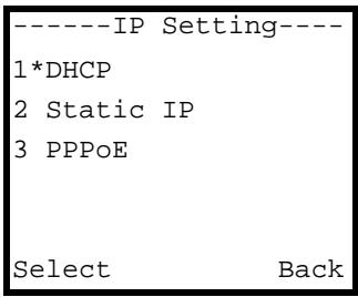
Figure 57 Menu > Network > WLAN Profiles > Add to Profile > IP Setting
The following table describes the labels in this screen.
Table 58 Menu > Network > WLAN Profiles > Add to Profile > IP Setting
| LABEL | DESCRIPTION |
| DHCP | Select this option to have the V630 get an IP address automatically. |
| Static IP | Select this option to assign the V630 an static IP address. |
| PPPoE | Select this option if the V630 needs to use a PPPoE account. |
| Select | Press this to choose the highlighted field in the menu. |
| Back | Press this to return to the previous screen. |
6.12 Static IP Settings
Press Menu > Network > WLAN Profiles > Add to Profile > IP Setting > Static IP to display the following menu. Use this menu to assign the V630 static IP address settings.
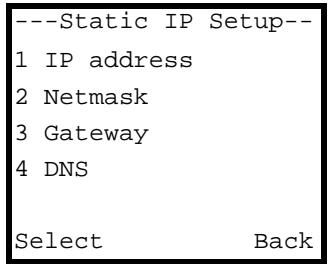
Figure 58 Menu > Network > WLAN Profiles > Add to Profile > IP Setting > Static IP
The following table describes the labels in this screen.
Table 59 Menu > Network > WLAN Profiles > Add to Profile > IP Setting > Static IP
| LABEL | DESCRIPTION |
| IP address | Select this option to specify the IP address the V630 uses. |
| Netmask | Select this option to specify the subnet mask the V630 uses |
| Gateway | Select this option to specify the IP address of the default gateway that the V630 uses. |
| DNS | Select this option to specify the IP address of the DNS server that the V630 uses. |
| Select | Press this to choose the highlighted field in the menu. |
| Back | Press this to return to the previous screen. |
6.13 Static IP Address Setup
Press Menu > Network > WLAN Profiles > Add to Profile > IP Setting > Static IP > IP address to display the following menu. Use this menu to specify the IP address the V630 uses. Configure the other static IP settings in the same manner.
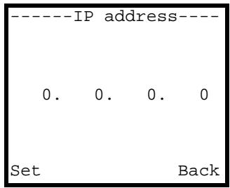
Figure 59 Menu > Network > WLAN Profiles > Add to Profile > IP Setting > Static IP > IP address
The following table describes the labels in this screen.
Table 60 Menu > Network > WLAN Profiles > Add to Profile > IP Setting > Static IP > IP address
| LABEL | DESCRIPTION |
| IP address | Use the V630's alphanumeric keypad to input the IP address the V630 is to use with this profile. Use the Down or Up key if you need to move the cursor. |
| Set | Press this to save your setting. |
| Back | Press this to return to the previous screen. |
6.14 PPPoE Settings
Press Menu > Network > WLAN Profiles > Add to Profile > IP Setting > PPPoE to display the following menu. If the V630 needs to use PPPoE, use this menu to go to screens where you configure the PPPoE user name and password.
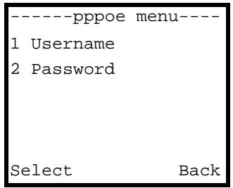
Figure 60 Menu > Network > WLAN Profiles > Add to Profile > IP Setting > PPPoE
The following table describes the labels in this screen.
Table 61 Menu > Network > WLAN Profiles > Add to Profile > IP Setting > PPPoE
| LABEL | DESCRIPTION |
| Username | Select this option to enter the user name for the PPPoE account. |
| Password | Select this option to enter the password for the PPPoE account. |
| Select | Press this to choose the highlighted field in the menu. |
| Back | Press this to return to the previous screen. |
6.15 PPPoEUsername
Press Menu > Network > WLAN Profiles > Add to Profile > IP Setting > PPPoE >Username to display the following menu. If the V630 needs to use PPPoE, use this menu to enter the PPPoE user name. The PPPoE password configuration works in the same manner.
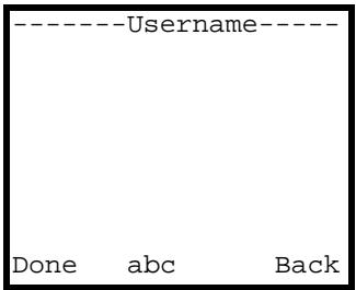
Figure 61 Menu > Network > WLAN Profiles > Add to Profile > IP Setting > PPPoE >Username
The following table describes the labels in this screen.
Table 62 Menu > Network > WLAN Profiles > Add to Profile > IP Setting > PPPoE >Username
| LABEL | DESCRIPTION |
| Username | Input the user name of the PPPoE account. When you press a key, other character options appear above the input field. Press a key multiple times to input one of the characters above. |
| Done | Press this to save your setting. |
| abc | Press # to switch between the lower-case and upper-case input modes. |
| Back | Press this to return to the previous screen. |
| Clear | After you start inputting text, Back changes to Clear. Press this to backspace. |
6.16 Selecting the SIP Account
Press Menu > Network > WLAN Profiles > Add to Profile > SIP Binding to display the following menu. You can configure more than one SIP account in the V630. Use this menu to select which SIP account this WLAN profile uses.
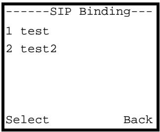
Figure 62 Menu > Network > WLAN Profiles > Add to Profile > SIP Binding
The following table describes the labels in this screen.
Table 63 Menu > Network > WLAN Profiles > Add to Profile > SIP Binding
| LABEL | DESCRIPTION |
| SIP Binding | This screen lists the SIP profiles configured in the V630. Select the one to use with this WLAN profile. |
| Select | Press this to choose the highlighted field in the menu. |
| Back | Press this to return to the previous screen. |
6.17 SIP Profiles
Press Menu > Network > SIP Profiles to display the following menu. Use this menu to select whether you want to go to the list of already configured profiles of SIP settings or create a profile of SIP settings.
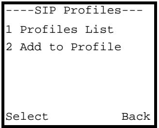
Figure 63 Menu > Network > SIP Profiles
The following table describes the labels in this screen.
Table 64 Menu > Network > SIP Profiles
| LABEL | DESCRIPTION |
| Profiles List | Look through and edit already configured profiles of SIP settings. |
| Add to Profile | Create a profile of WLAN settings. |
| Select | Press this to choose the highlighted field in the menu. |
| Back | Press this to return to the previous screen. |
6.18 SIP Profiles List
Press Menu > Network > SIP Profiles > Profiles List to display the following menu. Use this menu to look through and edit already configured profiles of WLAN settings.

You can configure multiple SIP profiles. See Section 6.16 on page 78 for how to select which SIP profile to use with a WLAN profile.
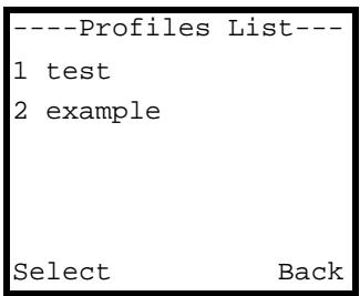
Figure 64 Menu > Network > SIP Profiles > Profiles List
The following table describes the labels in this screen.
Table 65 Menu > Network > SIP Profiles > Profiles List
| LABEL | DESCRIPTION |
| Profiles List | These are the already configured profiles of SIP settings. Select a profile to edit or delete it. |
| Select | Press this to choose the highlighted field in the menu. |
| Back | Press this to return to the previous screen. |
6.19 SIP Profile
Press Menu > Network > SIP Profiles > Profiles List and select a profile to display the following menu. Use this menu to choose whether to edit or delete the selected profile.
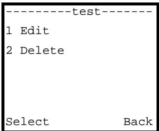
Figure 65 Menu > Network > SIP Profiles > Profiles List > Profile
The following table describes the labels in this screen.
Table 66 Menu > Network > SIP Profiles > Profiles List > Profile
| LABEL | DESCRIPTION |
| Edit | Select this to modify the profile. This opens a menu were you can select what you want to modify. See Section 6.7 on page 72 for details on the SIP profile editing screens. |
| Delete | Select this to remove the profile. |
| Select | Press this to choose the highlighted field in the menu. |
| Back | Press this to return to the previous screen. |
6.20 Adding a SIP Profile
Press Menu > Network > SIP Profiles > Add to Profile to display the following menu. Use this menu to create a profile of SIP settings.
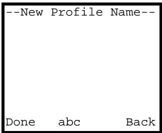
Figure 66 Menu > Network > SIP Profiles > Add to Profile
The following table describes the labels in this screen.
Table 67 Menu > Network > SIP Profiles > Add to Profile
| LABEL | DESCRIPTION |
| New Profile Name | Input the name of the profile. When you press a key, other character options appear above the input field. Press a key multiple times to input one of the characters above. |
| Done | Press this to save your setting. |
| abc | Press # to switch between the lower-case and upper-case input modes. |
| Back | Press this to return to the previous screen. |
| Clear | After you start inputting text, Back changes to Clear. Press this to backspace. |
6.21 Editing the New SIP Profile
Press Menu > Network > SIP Profiles > Add to Profile and specify a name to display the following menu. Use this menu to create a profile of SIP settings.
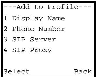
Figure 67 Menu > Network > SIP Profiles > Add to Profile > Name
The following table describes the labels in this screen.
Table 68 Menu > Network > SIP Profiles > Add to Profile > Name
| LABEL | DESCRIPTION |
| Display Name | Select this to specify the profile name that you want to display. This is the title that displays on the LCD main screen when the SIP account is registered. |
| Phone Number | Select this to specify the phone number of the SIP account. |
| SIP Server | Select this to specify the SIP server that the SIP account uses. |
| SIP Proxy | Select this to specify the SIP server that the SIP account uses. If you have more than one server's address, use this menu to enter the registrar server's address. |
| NAT traversal | Select this if you need to specify a STUN server, outbound proxy server, or NAT keep alive time. |
| Expire | Select this to specify the SIP server expire time. |
| Codec Order | Change the order for which codec the V630 attempts to use in making a call. |
| Select | Press this to choose the highlighted field in the menu. |
| Back | Press this to return to the previous screen. |
6.22 SIP Display Name
Press Menu > Network > SIP Profiles > Add to Profile, specify a name and then select Display Name to open the following menu. Use this menu to specify the profile name that you want to display.
Figure 68 Menu > Network > SIP Profiles > Add to Profile > Name > Display Name
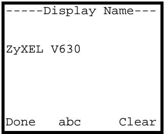
The following table describes the labels in this screen.
Table 69 Menu > Network > SIP Profiles > Add to Profile > Name > Display Name
| LABEL | DESCRIPTION |
| Display Name | Input the profile's display name. When you press a key, other character options appear above the input field. Press a key multiple times to input one of the characters above. |
| Done | Press this to save your setting. |
| abc | Press # to switch between the lower-case and upper-case input modes. |
| Clear | Press this to backspace. |
| Back | Press this to return to the previous screen. After you clear all the text, Clear changes to Back. |
6.23 SIP Phone Number
Press Menu > Network > SIP Profiles > Add to Profile, specify a name and then select Phone Number to open the following menu. Use this menu to specify the phone number of the SIP account.
Figure 69 Menu > Network > SIP Profiles > Add to Profile > Name > Phone Number
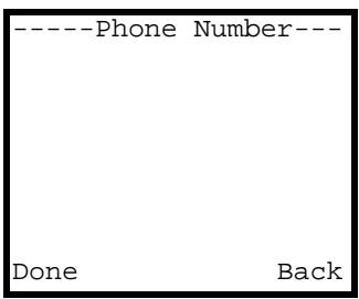
The following table describes the labels in this screen.
Table 70 Menu > Network > SIP Profiles > Add to Profile > Name > Phone Number
| LABEL | DESCRIPTION |
| Phone Number | Input the profile's SIP phone number. For example, if you have a SIP account like 1234567@voip-provider.com, your SIP account number is 1234567. When you press a key, other character options appear above the input field. Press a key multiple times to input one of the characters above. |
| Done | Press this to save your setting. |
| Back | Press this to return to the previous screen. |
| Clear | After you start inputting text, Back changes to Clear. Press this to backspace. |
6.24 SIP Server
Press Menu > Network > SIP Profiles > Add to Profile, specify a name and then select SIP Server to open the following menu. Use this menu to select whether you want to edit the SIP server's address or SIP port number.
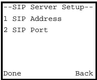
Figure 70 Menu > Network > SIP Profiles > Add to Profile > Name > SIP Server
The following table describes the labels in this screen.
Table 71 Menu > Network > SIP Profiles > Add to Profile > Name > SIP Server
| LABEL | DESCRIPTION |
| SIP Address | Select this to enter the IP address of the SIP server for this account. |
| SIP Port | Select this to enter the SIP port number of the SIP server for this account. |
| Select | Press this to choose the highlighted field in the menu. |
| Back | Press this to return to the previous screen. |
6.25 SIP Server Address
Press Menu > Network > SIP Profiles > Add to Profile, specify a name and then select SIP Server > SIP Address to open the following menu. Use this menu to enter the SIP server's address.
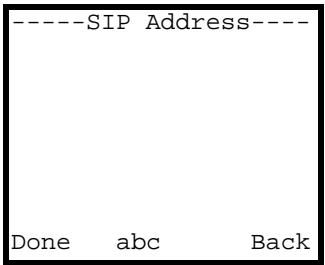
Figure 71 Menu > Network > SIP Profiles > Add to Profile > Name > SIP Server > SIP Address
The following table describes the labels in this screen.
Table 72 Menu > Network > SIP Profiles > Add to Profile > Name > SIP Server > SIP Address
| LABEL | DESCRIPTION |
| SIP Address | Enter the IP address or domain name of the SIP server for this account. If you have more than one server's address, enter the registrar server's address. When you press a key, other character options appear above the input field. Press a key multiple times to input one of the characters above. |
| Done | Press this to save your setting. |
| abc | Press # to switch between the lower-case and upper-case input modes. |
| Back | Press this to return to the previous screen. |
| Clear | After you start inputting text, Back changes to Clear. Press this to backspace. |
6.26 SIP Port Number
Press Menu > Network > SIP Profiles > Add to Profile, specify a name and then select SIP Server > SIP Address to open the following menu. Use this menu to enter the SIP server's port number.
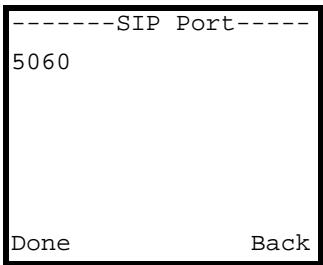
Figure 72 Menu > Network > SIP Profiles > Add to Profile > Name > SIP Server > SIP Port
The following table describes the labels in this screen.
Table 73 Menu > Network > SIP Profiles > Add to Profile > Name > SIP Server > SIP Port
| LABEL | DESCRIPTION |
| SIP Port | Enter the SIP port number that the SIP server uses. |
| Done | Press this to save your setting. |
| Back | Press this to return to the previous screen. |
| Clear | After you start inputting text, Back changes to Clear. Press this to backspace. |
6.27 SIP Proxy Setup
Press Menu > Network > SIP Profiles > Add to Profile, specify a name and then select SIP Proxy to open the following menu. Use this menu to specify which SIP proxy settings you want to enter.
Figure 73 Menu > Network > SIP Profiles > Add to Profile > Name > SIP Proxy
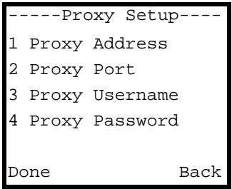
The following table describes the labels in this screen.
Table 74 Menu > Network > SIP Profiles > Add to Profile > Name > SIP Proxy
| LABEL | DESCRIPTION |
| Proxy Address | If the VoIP service provider provided a SIP proxy server address, select this to configure it. |
| Proxy Port | If the VoIP service provider provided a port number other than 5060, select this to configure it. |
| ProxyUsername | Select this to enter your SIP account's user name. |
| Proxy Password | Select this to enter your SIP account's password. |
| Select | Press this to choose the highlighted field in the menu. |
| Back | Press this to return to the previous screen. |
6.28 SIP Proxy Address
Press Menu > Network > SIP Profiles > Add to Profile, specify a name and then select SIP Proxy > Proxy Address to open the following menu. Use this menu to enter the SIP proxy server's address.
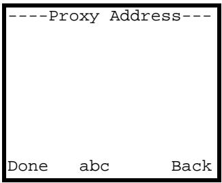
Figure 74 Menu > Network > SIP Profiles > Add to Profile > Name > SIP Proxy > Proxy Address
The following table describes the labels in this screen.
Table 75 Menu > Network > SIP Profiles > Add to Profile > Name > SIP Server > SIP Proxy > Proxy Address
| LABEL | DESCRIPTION |
| Proxy Address | Enter the IP address or domain name of the SIP proxy server for this account. When you press a key, other character options appear above the input field. Press a key multiple times to input one of the characters above. |
| Done | Press this to save your setting. |
| abc | Press # to switch between the lower-case and upper-case input modes. |
| Back | Press this to return to the previous screen. |
| Clear | After you start inputting text, Back changes to Clear. Press this to backspace. |
6.29 SIP Proxy Port
Press Menu > Network > SIP Profiles > Add to Profile, specify a name and then select SIP Proxy > Proxy Port to open the following menu. Use this menu to enter the SIP proxy server's port number.
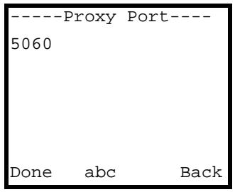
Figure 75 Menu > Network > SIP Profiles > Add to Profile > Name > SIP Proxy > Proxy Port
The following table describes the labels in this screen.
Table 76 Menu > Network > SIP Profiles > Add to Profile > Name > SIP Proxy > Proxy Address
| LABEL | DESCRIPTION |
| Proxy Port | Enter the SIP port number that the SIP proxy server uses. |
| Done | Press this to save your setting. |
| Back | Press this to return to the previous screen. |
| Clear | After you start inputting text, Back changes to Clear. Press this to backspace. |
6.30 SIP Proxy User Name
Press Menu > Network > SIP Profiles > Add to Profile, specify a name and then select SIP Proxy > ProxyUsername to open the following menu. Use this menu to enter the SIP account's user name.
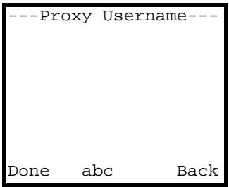
Figure 76 Menu > Network > SIP Profiles > Add to Profile > Name > SIP Proxy > ProxyUsername
The following table describes the labels in this screen.
Table 77 Menu > Network > SIP Profiles > Add to Profile > Name > SIP Proxy > ProxyUsername
| LABEL | DESCRIPTION |
| ProxyUsername | Enter the user name for this account. When you press a key, other character options appear above the input field. Press a key multiple times to input one of the characters above. |
| Done | Press this to save your setting. |
| abc | Press # to switch between the lower-case and upper-case input modes. |
| Back | Press this to return to the previous screen. |
| Clear | After you start inputting text, Back changes to Clear. Press this to backspace. |
6.31 SIP Proxy Password
Press Menu > Network > SIP Profiles > Add to Profile, specify a name and then select SIP Proxy > Proxy Password to open the following menu. Use this menu to enter the SIP account's user name.
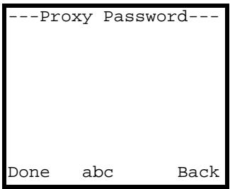
Figure 77 Menu > Network > SIP Profiles > Add to Profile > Name > SIP Proxy > Proxy Password
The following table describes the labels in this screen.
Table 78 Menu > Network > SIP Profiles > Add to Profile > Name > SIP Proxy > ProxyUsername
| LABEL | DESCRIPTION |
| Proxy Password | Enter the password for this account. When you press a key, other character options appear above the input field. Press a key multiple times to input one of the characters above. |
| Done | Press this to save your setting. |
| abc | Press # to switch between the lower-case and upper-case input modes. |
Table 78 Menu > Network > SIP Profiles > Add to Profile > Name > SIP Proxy > ProxyUsername
| LABEL | DESCRIPTION |
| Back | Press this to return to the previous screen. |
| Clear | After you start inputting text, Back changes to Clear. Press this to backspace. |
6.32 NAT Traversal
Press Menu > Network > SIP Profiles > Add to Profile, specify a name and then select NAT traversal to open the following menu. Use this menu to select which NAT traversal settings you want to enter.
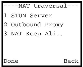
Figure 78 Menu > Network > SIP Profiles > Add to Profile > Name > NAT traversal
The following table describes the labels in this screen.
Table 79 Menu > Network > SIP Profiles > Add to Profile > Name > NAT traversal
| LABEL | DESCRIPTION |
| STUN Server | Select this to configure the V630 to get NAT information automatically from a STUN (Simple Traversal of User Datagram Protocol (UDP) through Network Address Translators) server. |
| Outbound Proxy | Select this if you have an outbound proxy server. |
| NAT Keep Alive | Select this to configure NAT keep alive to stop NAT routers between the V630 and the SIP server from dropping the SIP session. |
| Select | Press this to choose the highlighted field in the menu. |
| Back | Press this to return to the previous screen. |
6.33 STUN Setup
Press Menu > Network > SIP Profiles > Add to Profile, specify a name and then select NAT traversal > STUN Server to open the following menu. Use this menu to select whether you want to edit the STUN server's address or port number setting.

Figure 79 Menu > Network > SIP Profiles > Add to Profile > Name > NAT traversal > STUN Server
The following table describes the labels in this screen.
Table 80 Menu > Network > SIP Profiles > Add to Profile > Name > NAT traversal > STUN Server
| LABEL | DESCRIPTION |
| STUN Address | Select this to enter the IP address or domain name of the SIP server for this account. |
| STUN Port | Select this to enter the SIP port number of the SIP server for this account. |
| Select | Press this to choose the highlighted field in the menu. |
| Back | Press this to return to the previous screen. |
6.34 STUN Server Address
Press Menu > Network > SIP Profiles > Add to Profile, specify a name and then select NAT traversal > STUN Server > STUN Address to open the following menu. Use this menu to enter the STUN server's address.
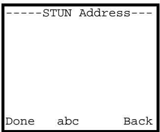
Figure 80 Menu > Network > SIP Profiles > Add to Profile > Name > NAT traversal > STUN Server > STUN Address
The following table describes the labels in this screen.
Table 81 Menu > Network > SIP Profiles > Add to Profile > Name > NAT traversal > STUN Server > STUN Address
| LABEL | DESCRIPTION |
| STUN Address | Enter the IP address or domain name of the STUN server. When you press a key, other character options appear above the input field. Press a key multiple times to input one of the characters above. |
| Done | Press this to save your setting. |
| abc | Press # to switch between the lower-case and upper-case input modes. |
| Back | Press this to return to the previous screen. |
| Clear | After you start inputting text, Back changes to Clear. Press this to backspace. |
6.35 STUN Port Number
Press Menu > Network > SIP Profiles > Add to Profile, specify a name and then select NAT traversal > STUN Server > STUN Port to open the following menu. Use this menu to enter the STUN server's port number.
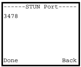
Figure 81 Menu > Network > SIP Profiles > Add to Profile > Name > NAT traversal > STUN Server > STUN Port
The following table describes the labels in this screen.
Table 82 Menu > Network > SIP Profiles > Add to Profile > Name > NAT traversal > STUN Server > STUN Port
| LABEL | DESCRIPTION |
| STUN Port | Enter the port number that the STUN server uses. |
| Done | Press this to save your setting. |
| Back | Press this to return to the previous screen. |
| Clear | After you start inputting text, Back changes to Clear. Press this to backspace. |
6.36 Outbound Proxy Setup
Press Menu > Network > SIP Profiles > Add to Profile, specify a name and then select NAT traversal > Outbound Proxy to open the following menu. Use this menu to select whether you want to edit the outbound proxy server's address or port number setting.
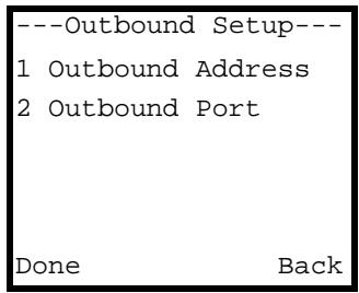
Figure 82 Menu > Network > SIP Profiles > Add to Profile > Name > NAT traversal > Outbound Proxy
The following table describes the labels in this screen.
Table 83 Menu > Network > SIP Profiles > Add to Profile > Name > NAT traversal > Outbound Proxy
| LABEL | DESCRIPTION |
| Outbound Address | Select this to enter the IP address or domain name of the outbound proxy server. |
| Outbound Port | Select this to enter the port number of the outbound proxy server. |
| Select | Press this to choose the highlighted field in the menu. |
| Back | Press this to return to the previous screen. |
6.37 Outbound Proxy Server Address
Press Menu > Network > SIP Profiles > Add to Profile, specify a name and then select NAT traversal > Outbound Proxy > Outbound Address to open the following menu. Use this menu to enter the outbound proxy server's address.
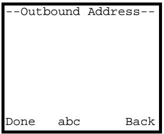
Figure 83 Menu > Network > SIP Profiles > Add to Profile > Name > NAT traversal > Outbound Proxy > Outbound Address
The following table describes the labels in this screen.
Table 84 Menu > Network > SIP Profiles > Add to Profile > Name > NAT traversal > Outbound Proxy > Outbound Address
| LABEL | DESCRIPTION |
| Outbound Address | Enter the IP address or domain name of the outbound proxy server. When you press a key, other character options appear above the input field. Press a key multiple times to input one of the characters above. |
| Done | Press this to save your setting. |
| abc | Press # to switch between the lower-case and upper-case input modes. |
| Back | Press this to return to the previous screen. |
| Clear | After you start inputting text, Back changes to Clear. Press this to backspace. |
6.38 Outbound Proxy Port Number
Press Menu > Network > SIP Profiles > Add to Profile, specify a name and then select NAT traversal > Outbound Proxy > Outbound Port to open the following menu. Use this menu to enter the outbound proxy server's port number.
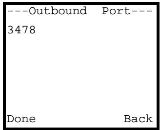
Figure 84 Menu > Network > SIP Profiles > Add to Profile > Name > NAT traversal > Outbound Proxy > Outbound Port
The following table describes the labels in this screen.
Table 85 Menu > Network > SIP Profiles > Add to Profile > Name > NAT traversal > Outbound Proxy > Outbound Port
| LABEL | DESCRIPTION |
| Outbound Port | Enter the port number that the outbound proxy server uses. |
| Done | Press this to save your setting. |
| Back | Press this to return to the previous screen. |
| Clear | After you start inputting text, Back changes to Clear. Press this to backspace. |
6.39 NAT Keep Alive Time
Press Menu > Network > SIP Profiles > Add to Profile, specify a name and then select NAT traversal > NAT Keep Alive to open the following menu. Use this menu to set the NAT keep alive time.
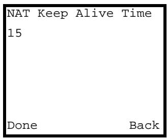
Figure 85 Menu > Network > SIP Profiles > Add to Profile > Name > NAT traversal > NAT Keep Alive
The following table describes the labels in this screen.
Table 86 Menu > Network > SIP Profiles > Add to Profile > Name > NAT traversal > NAT Keep Alive
| LABEL | DESCRIPTION |
| NAT Keep Alive Time | Enter the number of NAT keep alive time seconds. |
| Done | Press this to save your setting. |
| Back | Press this to return to the previous screen. |
| Clear | After you start inputting text, Back changes to Clear. Press this to backspace. |
6.40 SIP Server Expire Time
Press Menu > Network > SIP Profiles > Add to Profile, specify a name and then select Expire to open the following menu. Use this menu to set the SIP server expiration time.
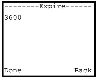
Figure 86 Menu > Network > SIP Profiles > Add to Profile > Name > Expire
The following table describes the labels in this screen.
Table 87 Menu > Network > SIP Profiles > Add to Profile > Name > Expire
| LABEL | DESCRIPTION |
| Expire | Enter the SIP server's expiration time (in seconds). This is how long an entry remains registered with the SIP server. After the time period expires, the SIP register server deletes the V630's entry from the database of registered SIP numbers. Different register servers may use different time periods. The V630 sends another registration request after half of the time period configured here has expired. |
| Done | Press this to save your setting. |
| Back | Press this to return to the previous screen. |
| Clear | After you start inputting text, Back changes to Clear. Press this to backspace. |
6.41 Codec Order
Press Menu > Network > SIP Profiles > Add to Profile, specify a name and then select Codec Order to open the following menu. Use this menu to set the order for which codec the V630 attempts to use in making a call.
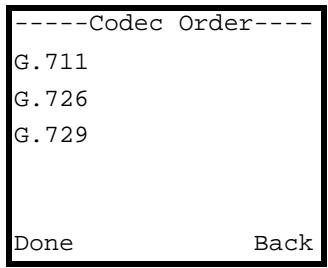
Figure 87 Menu > Network > SIP Profiles > Add to Profile > Name > Codec Order
The following table describes the labels in this screen.
Table 88 Menu > Network > SIP Profiles > Add to Profile > Name > Code Order
| LABEL | DESCRIPTION |
| Codec Order | Use the Up or Down key to change the order for which codec the V630 attempts to use in making a call. |
Table 88 Menu > Network > SIP Profiles > Add to Profile > Name > Code Order
| LABEL | DESCRIPTION |
| Done | Press this to save your setting. |
| Cancel | Press this to return to the previous screen. |
6.42 Ping Test
Press Menu > Network > Ping test to display the following menu. Use this menu to have the V630 send a ping to an IP address to check the network connectivity to a device.
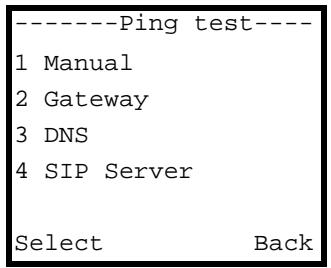
Figure 88 Menu > Network > Ping test
The following table describes the labels in this screen.
Table 89 Menu > Network > Ping test
| LABEL | DESCRIPTION |
| Manual | Select this to go to a menu where you can specify an IP address to which to send a ping. |
| Gateway | Select this to send a ping to check the connectivity to the V630's gateway device. |
| DNS | Select this to send a ping to check the connectivity to the V630's DNS server. |
| SIP Server | Select this to send a ping to check the connectivity to the V630's SIP server. |
| SIP Proxy | Select this to send a ping to check the connectivity to the V630's SIP proxy server. |
| Outbound Proxy | Select this to send a ping to check the connectivity to the V630's SIP outbound proxy server. |
| Stun Server | Select this to send a ping to check the connectivity to the V630's STUN server. |
| Select | Press this to choose the highlighted field in the menu. |
| Back | Press this to return to the previous screen. |
6.43 Manual Ping Test
Press Menu > Network > Ping test > Manual to display the following menu. Use this menu to have the V630 send a ping to an IP address to check the network connectivity to a device.
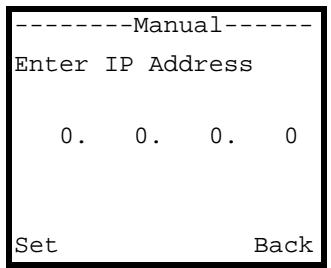
Figure 89 Menu > Network > Ping test > Manual
The following table describes the labels in this screen.
Table 90 Menu > Network > Ping test > Manual
| LABEL | DESCRIPTION |
| IP address | Use the V630's alphanumeric keypad to input the IP address to which the V630 is to send a ping. Use the Down or Up key if you need to move the cursor. |
| Set | Press this to save your setting. |
| Back | Press this to return to the previous screen. |
6.44 Ping Test in Progress
Here is an example of the results when the V630 performs a ping test (in this case to the gateway).
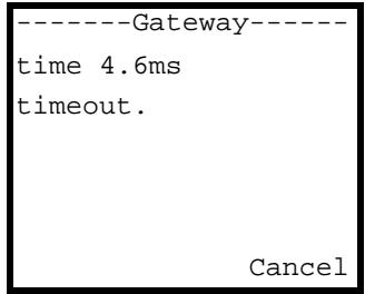
Figure 90 Menu > Network > Ping test (In Progress)
The following table describes the labels in this screen.
Table 91 Menu > Network > Ping test (In Progress)
| LABEL | DESCRIPTION |
| time | This is how many milliseconds it took to get a response from the IP address to which the V630 sent a ping. |
| timeout. | Timeout means the V630 did not receive a reply from the IP address to which it sent a ping. |
| Cancel | Press this to stop the ping test and return to the previous screen. |
6.45 Reconnect
Press Menu > Network > Re-connect to display the following screen. Use this menu to reconnect to the AP.
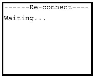
Figure 91 Menu > Network > Re-connect
The following table describes the labels in this screen.
Table 92 Menu > Network > Re-connect
| LABEL | DESCRIPTION |
| Re-connect | The V630 attempt to re-establish its connection to the AP. |
The Phonebook
Use the V630's phonebook to store the names and phone numbers of your contacts. You can either add phonebook entries yourself, or they can be supplied via auto provisioning.
The entries can be regular phone numbers (that you use a SIP server to call) or Peer to Peer (P2P) numbers. Use P2P entries to call directly to the callee's SIP phone number and IP address without using a SIP server. This is also called a ““Point to Point”, or “IP-to-IP” call.
The following sections describe how to use the phonebook.
7.1 Opening the Phonebook
While in the main screen, press the Right key to open the phonebook. The contact list appears.
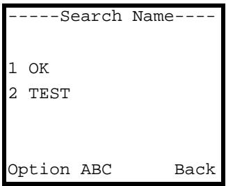
Figure 92 Phonebook
7.2 Adding a Phonebook Entry
To add a contact into the V630's phonebook, either add the number from your call log or do the following.
1 While in the main screen, press the Right key to open the phonebook. The contact list appears.
2 Press Option > Add to display the following screen.
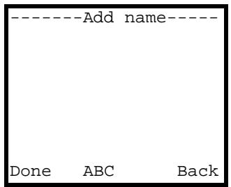
Figure 93 Phonebook > Option > Add
The following table describes the labels in this screen.
Table 93 Menu > Network > SIP Profiles > Add to Profile
| LABEL | DESCRIPTION |
| Find/add name | Input the name of the contact. When you press a key, other character options appear above the input field. Press a key multiple times to input one of the characters above. |
| Done | Press this to save your setting. |
| abc | Press # to switch between the lower-case and upper-case input modes. |
| Back | Press this to return to the previous screen. |
| Clear | After you start inputting text, Back changes to Clear. Press this to backspace. |
3 The following screen displays. Press the Left key (Yes).
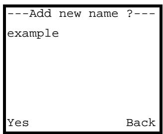
Figure 94 New Contact Name
4 A screen displays with the contact's name at the top. Use the alphanumeric keypad to enter the contact's phone number. Then press Done.
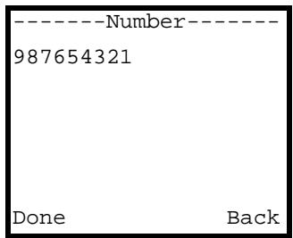
Figure 95 New Contact Number
5 Select SIP mode if you will use a SIP server to call the callee. Select P2P mode if you will call the callee's SIP phone number and IP address without using a SIP serve
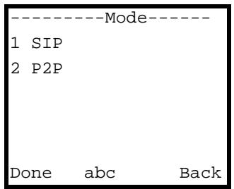
Figure 96 Selecting the Calling Mode
6 If you selected SIP, skip to step 8 on page 99. Enter the callee's IP address and press Done.
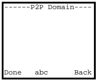
Figure 97 Entering a Peer's IP Address
7 Enter the callee's SIP port number (if it is different from the default of 5060) and press Done. Then press the Left key to start the call.
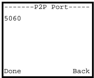
Figure 98 Entering a Peer's Port Number
8 Select a group to add the contact to, or just select None to not add the contact to a group.
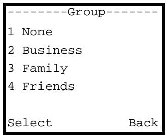
Figure 99 New Contact Group
9 The contact's entry is stored alphabetically in the phonebook. Note that the alphabetical order starts over for the entries that start with lower-case letters.
7.3 Selecting a Phonebook Entry
1 While in the main screen, press the Right key to open the phonebook's contact list.
2 Either use the Up and Down keys to scroll through the entries, or use the alphanumeric keypad to enter the first letter of a contact's name. For example, press the 2 key three times to enter a "C". The cursor jumps to the first entry starting with that letter (if no entries start with that letter, nothing happens).

The numbers that display to the left of a contact's phone number are index numbers only - you cannot use them to select an entry.
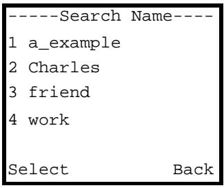
Figure 100 Phonebook
7.4 Calling a Phonebook Contact
Here's how to call a number you previously entered into the V630's phonebook.
1 While in the main screen, press the Right key to open the phonebook's contact list.
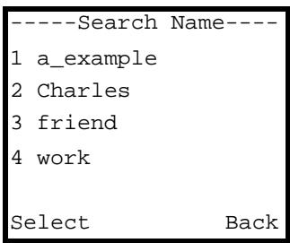
Figure 101 Phonebook
2 Highlight the entry you want to call and press the green Talk key to begin the call.
7.5 Calling a Number Not in the Phonebook
To call a number that is not in your V630's phonebook, from the main screen, use the alphanumeric keypad to dial the number and press the green Talk key to start the call.
7.6 Checking a Contact's Details
Do the following to check a contact's number and group setting.
1 While in the main screen, press the Right key to open the phonebook's contact list.
2 Select the entry you want to check. Press Option > Detail to display the following screen. Scroll down to see the contact's number and which group it belongs to (if any).
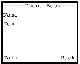
Figure 102 Contact Details
7.7 Editing a Phonebook Entry
Take the following steps to change the details of a contact you already entered into the V630's phonebook.
1 While in the main screen, press the Right key to open the phonebook's contact list.
2 Select the entry you want to change. Press Option > Edit to display the following screen for editing the contact name. Edit the name and press Done when you are finished.
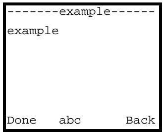
Figure 103 Editing a Contact Name
3 Use this screen to edit the contact's phone number and press Done.
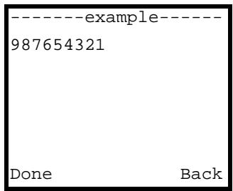
Figure 104 Editing a Contact Number
4 Select which group to add the contact to, or just select None to not add the contact to a group.
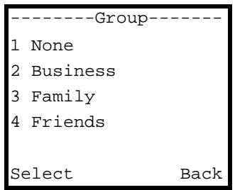
Figure 105 New Contact Group
5 The contact's entry is now edited and stored alphabetically in the phonebook. Note that the alphabetical order starts over for the entries that start with lower-case letters.
7.8 Deleting a Phonebook Entry
Take the following steps to remove a contact's entry from the V630's phonebook.
1 While in the main screen, press the Right key to open the phonebook's contact list.
1 Select the entry you want to remove. Press Option > Delete. The following screen displays.
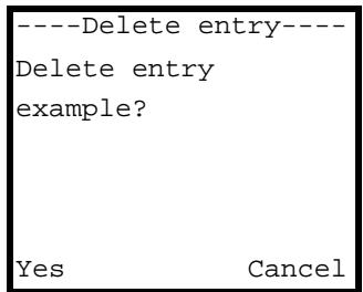
Figure 106 Delete a Phonebook Entry
2 Press Yes to delete the entry, or press Cancel to return to the previous screen.
7.9 Contact Groups
Use contact groups to specify the ring tone for incoming calls from the group's members. Do the following to edit a contact group.
1 While in the main screen, press the Right key to open the phonebook's contact list. Press Option > Group to display the following screen. Select the group that you want to edit.
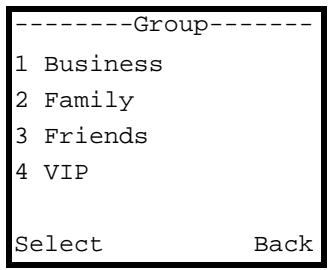
Figure 107 Contact Groups
2 Select whether to edit the group's members (see Section 7.10 on page 103) or set the ring tone to use for incoming calls from the group's members (see Section 7.11 on page 104).
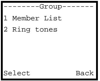
Figure 108 Contact Group Selected
7.10 Editing a Contact Group's Members
If you selected Member List in Figure 108 on page 103, the following menu displays. This menu lists the group's members.
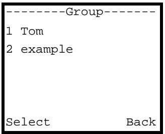
Figure 109 Contact Group Selected
Select a member to display the following screen. Select Edit to modify the contact's details (see Section 7.7 on page 101 for more on this). Select Delete to remove the contact from the phone book.

Delete in this screen actually removes the contact from the phone book, not just from the contact group.
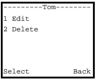
Figure 110 Contact Group Member Selected
7.11 Editing a Contact Group's Ring Tone
If you selected Ring tones in Figure 108 on page 103, the following menu displays. Select the ring tone for incoming calls from the selected contact group's members.
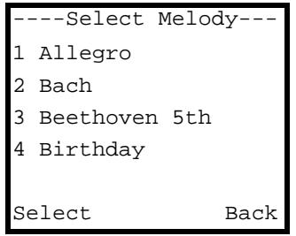
Figure 111 Contact Group Ring tones
7.12 Speed Dial
Set up speed dial entries to be able to call someone by dialing a single number.
7.13 Adding a Speed Dial Entry
Do the following to make an existing phonebook entry into a speed dial entry.
1 While in the main screen, press the Right key to open the phonebook's contact list.
2 Select the entry you want to add to speed dial. Press Option > Speed Dial to display the following screen. Select for which key you want to create a speed dial entry. This example uses key 2.
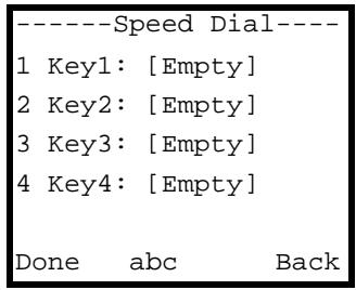
Figure 112 Speed Dial
3 The following screen displays. Select Yes to add the contact as a speed dial entry.
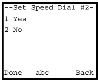
Figure 113 Set the Speed Dial Entry
7.14 Editing a Speed Dial Entry
Do the following to edit an existing speed dial entry.
1 While in the main screen, press the Right key to open the phonebook's contact list.
2 Select the entry you want to edit. Press Option > Speed Dial to display the following screen. Select the speed dial entry you want to edit. This example uses 2.

Figure 114 Speed Dial
The following screen displays. Select Change to set whether or not to use the contact as a speed dial entry.

Delete in this screen removes the contact from the phonebook, not just from the contact group.
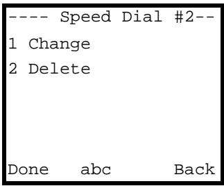
Figure 115 Speed Dial Entry Change
3 The following screen displays. Select No to not use the contact as a speed dial entry.
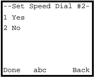
Figure 116 Set the Speed Dial Entry
7.15 Deleting All Phonebook Entries
Take the following steps to remove all of your contact entries from the V630's phonebook.
1 While in the main screen, press the Right key to open the phonebook's contact list.
2 Press Option > Delete All. The following screen displays.

Figure 117 Delete All Phonebook Entries
3 Press Yes to remove all of the phonebook entries, or press Cancel to return to the previous screen.
7.16 Phonebook Storage Space
Do the following to see how much storage space the phonebook has free for entries.
1 While in the main screen, press the Right key to open the phonebook's contact list.
2 Press Option > Memory status. The following screen displays briefly. This screen shows how many more phonebook entries you can add.

Figure 118 Delete All Phonebook Entries
This chapter describes the options you can use during a call.
8.1 Call Volume
During a call, press the Up or Down key to adjust the volume.
8.2 Call Options
During a call, press Option to open the following screen.
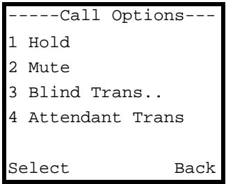
Figure 119 Call Options
The following table describes the labels in this screen.
Table 94 Call Options
| LABEL | DESCRIPTION |
| Hold/Unhold | Select this to put the call on hold or take it off hold. |
| Mute/Unmute | Select this to mute or unmute the call. When you mute the call, you can still hear the other party, but the other party cannot hear you. |
| Blind Transfer | Select this to transfer the call to another number without notifying the recipient. You can transfer a call that you make (outgoing) or receive (incoming). |
| Attendant Transfer | Select this to transfer the call after consulting with the recipient. |
| Phone Book | Select this to open the V630's phone book. |
| Use Speaker | Select this to turn on the speaker phone function. |
| Select | Press this to choose the highlighted field in the menu. |
| Back | Press this to return to the previous screen. |
PART III
The Web
Configurator
Introducing the Web Configurator (111)
Information Screen (115)
WLAN Profile (117)
Call Setting (123)
Phone Book (125)
SIP Account Setup (127)
Auto Provision (135)
Introducing the Web Configurator
This chapter describes how to access the V630's web configurator and provides an overview of its screens.
9.1 Web Configurator Overview
The web configurator is an HTML-based management interface that allows easy V630 setup and management via Internet browser. Use Internet Explorer 6.0 and later versions. The recommended screen resolution is 1024 by 768 pixels.
In order to use the web configurator you need to allow:
- Web browser pop-up windows from your device. Web pop-up blocking is enabled by default in Windows XP SP (Service Pack) 2.
- JavaScripts (enabled by default).
- Java permissions (enabled by default).
See Appendix C on page 189 if you want to make sure these functions are allowed in Internet Explorer.
9.2 Accessing the Web Configurator
1 Launch your web browser.

Before you can access the web configurator, you must enable it in the Menu > Setup > Phone Setting > Web Configurator LCD screen.
2 Enter the V630's IP address as the URL. If the V630 got an IP address automatically, you may need to check the Menu > Setup > Information > TCP/IP LCD screen to find it's IP address (see Section 5.27 on page 64). The following screen displays.
Figure 120 Password Screen
3 For user access, type password (default) as the password. For administrator access, type admin (default). Click Login.
4 It is recommended that you change your password. See Section 16.1 on page 139 for details.
5 The Device Information screen displays.
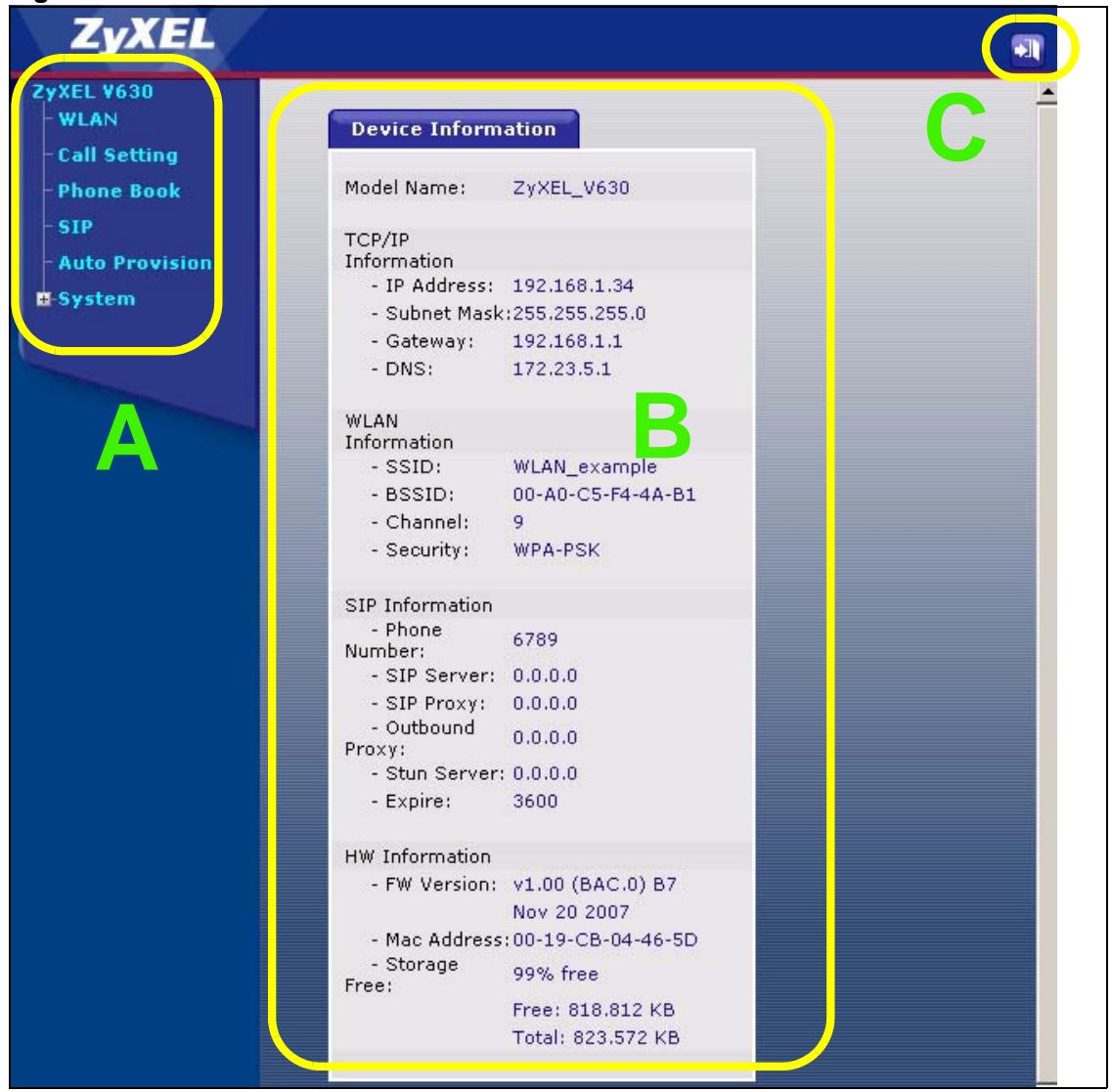
Figure 121 The Status Screen
As illustrated above, the web configurator screen is divided into four parts.
- A - navigation panel
- B - main window
- C - logout icon
9.2.1 Navigation Panel
Use the menu items on the navigation panel to open screens and configure the V630's features. The following table describes the menu items.
Table 95 Navigation Panel Summary
| LINK | TAB | FUNCTION |
| WLAN | WLAN Profile | Use this screen to configure WLAN profile settings. |
| Call Setting | Call Setting | Use this screen to configure call forwarding and whether or not the V630 sends its phone number to callees. |
| Phone Book | Phone Book | Use these screens to configure contact entries. |
Table 95 Navigation Panel Summary
| LINK | TAB | FUNCTION |
| SIP | SIP Profile | Use this screen to configure the V630 to use a SIP account. |
| Auto Provision | Auto Provision | Use this screen if you have an auto-provisioning server on the network. |
| System | ||
| Change Passwd | Basic | Use this screen to change the user password. |
| System | Use this screen to change the administrator password. | |
| Information | This screen displays the current status of the V630, its system resources, and current TCP/IP, WLAN, and SIP settings. | |
| Upgrade FW | Use this screen to upload firmware to the V630. |
9.2.2 Main Window
The main window displays information and configuration fields. It is discussed in the rest of this document.
The Information screen displays after you log in. See Chapter 10 on page 115 for more information about the Information screen.
Information Screen
Use the Information screen to see the current status of the V630, its system resources, and current TCP/IP, WLAN, and SIP settings.
10.1 Information Screen
Click System > Information to open this screen.
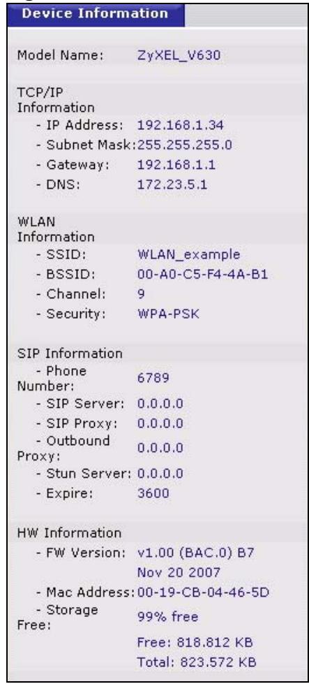
Figure 122 Information Screen
Each field is described in the following table.
Table 96 Information Screen
| LABEL | DESCRIPTION |
| Model Name | This field displays the V630's model name. |
| TCP/IP Information | These fields display the V630's current TCP/IP settings. |
| IP Address | This field displays the current IP address of the V630 on the WLAN. |
| Subnet Mask | This field displays the current subnet mask on the WLAN. |
| Gateway | This field displays the IP address of the router that forwards the V630's traffic. |
| DNS | This is the IP address of the DNS (Domain Name System) server your V630 uses. |
| WLAN Information | These fields display the V630's current wireless LAN settings. |
| SSID | This is theSSID (name) of the wireless network that the V630 is currently using. |
| BSSID | This is the V630's MAC (Media Access Control) address. Every network device has a unique MAC address that identifies it across the network. |
| Channel | This is the radio frequency that the V630 is currently using. |
| Security | This is the type of wireless security that the V630 is currently using. The V630 supports WEP, WPA PSK, WPA2 PSK, WPA, and WPA2. |
| SIP Information | These fields display the V630's current SIP settings. |
| Phone Number | This is the SIP account's phone number. |
| SIP Server | This is the address of the SIP server for the SIP account. |
| SIP Proxy | This is the address of the SIP proxy server for the SIP account. |
| Outbound Proxy | This is the address of the outbound proxy server for the SIP account. |
| Stun Server | This is the address of the STUN server for the SIP account. |
| Expire | This is the SIP server expire time. |
| HW Information | These fields display the V630's hardware settings and status. |
| FW Version | This is the firmware (embedded software) version and creation date. |
| Mac Address | This is the V630's MAC (Media Access Control) address. Every network device has a unique MAC address that identifies it across the network. |
| Storage Free | This shows how much of the V630's storage space is available. |
Use the WLAN Profile screen to configure profiles of wireless and TCP/IP settings. You can also select which SIP profile each WLAN profile uses.
11.1 Wireless Network Overview
The following figure provides an example of a wireless network.
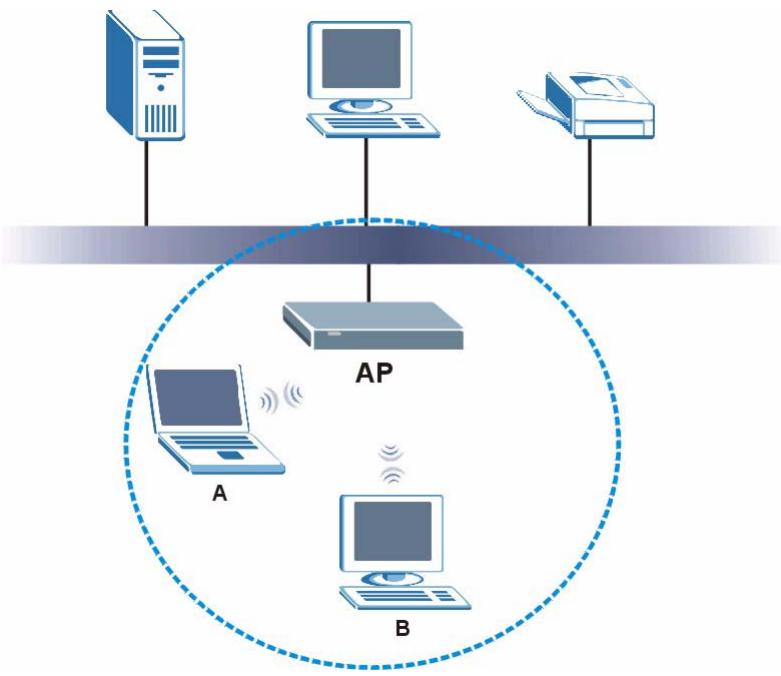
Figure 123 Example of a Wireless Network
The wireless network is the part in the blue circle. In this wireless network, devices A and B are called wireless clients. The wireless clients use the access point (AP) to interact with other devices (such as the printer) or with the Internet. Your V630 is a wireless client.
Every wireless network must follow these basic guidelines.
- Every wireless client in the same wireless network must use the same SSID.
The SSID is the name of the wireless network. It stands for Service Set IDentity.
- If two wireless networks overlap, they should use different channels.
Like radio stations or television channels, each wireless network uses a specific channel, or frequency, to send and receive information.
- Every wireless client in the same wireless network must use security compatible with the AP.
Security stops unauthorized devices from using the wireless network. It can also protect the information that is sent in the wireless network.
11.2 Wireless Security Overview
The following table shows the relative strengths of common types of wireless security. Use the strongest security that every wireless client in the wireless network supports.
Table 97 Wireless Security Types
| Weakest ↓ Strongest | NO RADIUS SERVER | RADIUS SERVER |
| No Security | WPA | |
| Static WEP | ||
| WPA-PSK | ||
| WPA2-PSK | WPA2 |
If you have a RADIUS server, you can use WPA or WPA2 so users have to log into the wireless network before using it. This is called user authentication. RADIUS servers are more common in businesses (WPA and WPA2 are also called the enterprise version of WPA).
If you do not have a RADIUS server, the strongest wireless security you can use is WPA2-PSK (WPA2-PSK and WPA-PSK are also known as the personal version of WPA).

It is recommended that wireless networks use WPA-PSK, WPA, or stronger security. WEP is better than no security, but it is still possible for unauthorized devices to figure out the original information pretty quickly.
When you select WPA2 or WPA2-PSK in your V630, you can also select an option (WPA Compatible) to support WPA as well. In this case, if some wireless clients support WPA and some support WPA2, you should set up WPA2-PSK or WPA2 (depending on the type of wireless network login) and select the WPA Compatible option in the V630.
11.2.1 SSD
Normally, the AP acts like a beacon and regularly broadcasts the SSID in the area. You can hide the SSID instead, in which case the AP does not broadcast the SSID. In addition, you should change the default SSID to something that is difficult to guess.
This type of security is fairly weak, however, because there are ways for unauthorized devices to get the SSID. In addition, unauthorized devices can still see the information that is sent in the wireless network.
11.2.2 User Authentication
You can use WPA or WPA2 to have a RADIUS server authenticate users before they can use the wireless network. You store each user's user name and password on the RADIUS server. However, every wireless client in the wireless network has to support IEEE 802.1x to do this.
Unauthorized devices can still see the information that is sent in the wireless network, even if they cannot use the wireless network. Furthermore, there are ways for unauthorized wireless users to get a valid user name and password. Then, they can use that user name and password to use the wireless network.
11.2.3 Encryption
Wireless networks can use encryption to protect the information that is sent in the wireless network. Encryption is like a secret code. If you do not know the secret code, you cannot understand the message.
Many types of encryption use a key to protect the information in the wireless network. The longer the key, the stronger the encryption. Every wireless client in the wireless network must have the same key.
11.3 IP Address Assignment
Every computer on a network must have a unique IP address.
11.3.1 DHCP Client
The V630 can get an IP address automatically if the network has a DHCP (Dynamic Host Control Protocol) server to give them out.
11.3.2 Static IP
If you have a static (fixed) IP address from the ISP, you can manually assign it to the V630's WAN port.
11.3.3 PPPoE
The V630 supports PPPoE (Point-to-Point Protocol over Ethernet) for a dial-up connection. You will need a user name and password from the Internet Service Provider (ISP).
11.4 DNS Server
A DNS (Domain Name System) server maps domain names (like www.zyxel.com) to their corresponding IP addresses (204.217.0.2 in the case of www.zyxel.com). This lets you use domain names to access web sites without having to know their IP addresses. When using DHCP, the V630 can receive the IP address of a DNS server automatically (along with the V630's own IP address). With a static IP address, you can also manually enter a DNS server IP address in the V630.
11.5 WLAN Profile Screen
Click WLAN to open the following screen.
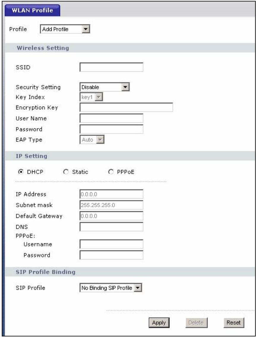
Figure 124 WLAN
The following table describes the general wireless LAN labels in this screen.
Table 98 WLAN
| LABEL | DESCRIPTION |
| Profile | Select a profile of WLAN settings to edit or select Add Profile to create a new one.Note: You cannot edit the WLAN profile that the V630 is currently using. |
| SSID | Enter theSSID (Service Set IDentity) of the wireless network to which you want to connect the V630. |
| Security Setting | Select the type of security that the wireless network uses. Select Disable if the wireless network does not use security. |
Table 98 WLAN
| LABEL | DESCRIPTION |
| Key Index | Select a default WEP key to use for data encryption. The key displays in the adjacent field. |
| Encryption Key | Enter the WEP key in the field provided.If you select 64 Bits in the WEP field.Enter either 10 hexadecimal digits in the range of “A-F”, “a-f” and “0-9” (for example, 11AA22BB33) for HEX key type.orEnter 5 ASCII characters (case sensitive) ranging from “a-z”, “A-Z” and “0-9” (for example, MyKey) for ASCII key type.If you select 128 Bits in the WEP field.Enter either 26 hexadecimal digits in the range of “A-F”, “a-f” and “0-9” (for example, 00112233445566778899AABBCC) for HEX key type.orEnter 13 ASCII characters (case sensitive) ranging from “a-z”, “A-Z” and “0-9” (for example, MyKey12345678) for ASCII key type.Note: The values for the WEP keys must be set up exactly the same on all wireless devices in the same wireless LAN. ASCII WEP keys are case sensitive. |
| User Name | When using WPA or WPA2, enter your user name here. |
| Password | When using WPA or WPA2, enter your password here. |
| EAP Type | When using WPA-EAP or WPA2-EAP, select the type of EAP authentication that the wireless network uses (or select Auto). |
| IP Setting | Select DHCP if you do not have a fixed IP address to use.Select Static if you were given a fixed IP address information to use. Then fill in the IP Address, Subnet Mask, Default Gateway and DNS fields.Select PPPoE if the V630 needs to use a PPPoE account. You will also need a PPPoE user name and password to use this. |
| IP Address | If you set the IP Setting to Static, enter the V630's IP address here. |
| Subnet Mask | If you set the IP Setting to Static, enter the V630's subnet mask here. |
| Default Gateway | If you set the IP Setting to Static, enter the IP address of the default gateway here.The default gateway is the device on the network that your V630 uses to access other networks (like the Internet). |
| DNS | If you set the IP Setting to Static, enter the DNS (Domain Name System) server your V630 uses here. |
| PPPoE | |
| Username | If you set the IP Setting to PPPoE, enter the user name for the PPPoE account here. |
| Password | If you set the IP Setting to PPPoE, enter the password for the PPPoE account here. |
| SIP Profile | Select the profile of SIP settings to use with this WLAN profile. |
| Apply | Click Apply to save your changes back to the V630. |
| Delete | Click Delete to remove the profile. |
| Reset | Click Reset to return the screen to the most recently saved settings. |
This chapter discusses the Call Setting screen.
12.1 Call Setting Screen
Click Call Setting to display the following screen. Use this screen to configure call forwarding for incoming calls and caller ID.
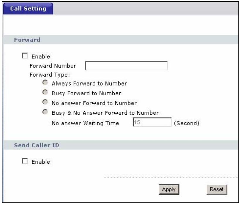
Figure 125 Call Setting
The following table describes the labels in this screen.
Table 99 Call Setting
| LABEL | DESCRIPTION |
| Enable | Select this check box to turn on call forwarding. This setting applies to all call forwarding on the V630. |
| Forward Number | Specify the phone number to which the V630 should forward incoming calls. |
Table 99 Call Setting
| LABEL | DESCRIPTION |
| Forward Type | Select Always Forward to Number to forward all calls to the specified number (regardless of whether or not your line is busy). Select Busy Forward to Number to forward calls when your line is busy. Select No Answer Forward to Number to forward calls when you do not answer the phone. You will be able to specify how long the V630 waits before forwarding an unanswered call. Select Busy & No Answer Forward to Number to forward calls when your line is busy or you do not answer the phone. Specify how long the V630 waits before forwarding an unanswered call. |
| Send Caller ID | Select this to have the V630 send your phone number to the phones you call. |
| Apply | Click Apply to save your changes back to the V630. |
| Reset | Click Reset to return the screen to the most recently saved settings. |
This chapter discusses the Phone Book screens.
13.1 Phone Book Screen
Use this screen to manage your phone book list of contacts. Click Phone Book to open the following screen.
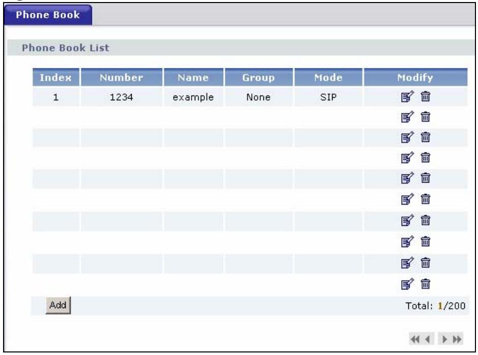
Figure 126 Phone Book
The following table describes the labels in this screen.
Table 100 Phone Book
| LABEL | DESCRIPTION |
| Index | This shows the index number of the contact's entry. |
| Number | This is the contact's phone number. |
| Name | This is the contact's name. |
| Group | This is the group to which the contact belongs (if any). You can use the LCD menus to assign a different ring for incoming calls from each group. |
| Mode | This shows whether you use a SIP server to call the contact or a direct peer-to-peer call. |
| Modify | Click the Edit icon to change this entry's details. Click the Remove icon to delete the entry from the phonebook. If you do this, the information cannot be recovered. |
| Add | Click this to create a new phone book entry. |
| Total | This shows how many phone book entries the V630 has out of its total possible number of entries. Use the navigation arrows to go to other pages of entries. |
13.1.1 Phone Book Add or Edit Screen
Use this screen to add or edit phone book entries. Click Phone Book. The following screen displays.
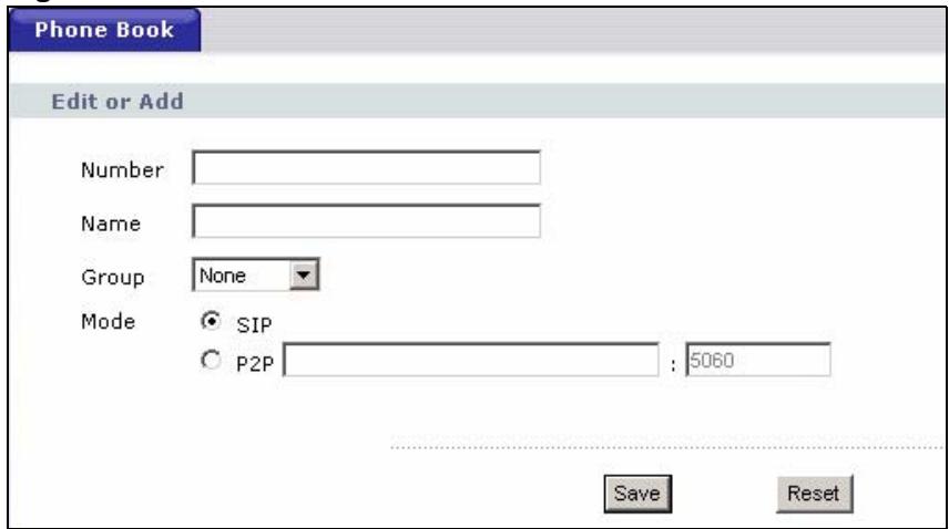
Figure 127 Phone Book > Add
The following table describes the labels in this screen.
Table 101 Phone Book > Add
| LABEL | DESCRIPTION |
| Number | Enter the contact's phone number. |
| Name | Enter the contact's name. |
| Group | Select the group to which the contact should belong (if any). You can use the LCD menus to assign a different ring for incoming calls from each group. |
| Mode | Select SIP if you will use a SIP server to call the contact. Select P2P if you will make a direct peer-to-peer call to the contact. For P2P you must also enter the callee's IP address. Enter the callee's SIP port number if it is different from the default of 5060. |
| Save | Click Save to save your changes back to the V630. |
| Reset | Click Reset to return the screen to the most recently saved settings. |
SIP Account Setup
This chapter discusses the V630's VoIP > SIP screens.
14.1 Introduction to VoIP
VoIP (Voice over IP) is the sending of voice signals over the Internet Protocol. This allows you to make phone calls and send faxes over the Internet at a fraction of the cost of using the traditional circuit-switched telephone network. You can also use servers to run telephone service applications like PBX services and voice mail. Internet Telephony Service Provider (ITSP) companies provide VoIP service. A company could alternatively set up an IP-PBX and provide its own VoIP service.
Circuit-switched telephone networks require 64 kilobits per second (kbps) in each direction to handle a telephone call. VoIP can use advanced voice coding techniques with compression to reduce the required bandwidth.
14.1.1 Introduction to SIP
The Session Initiation Protocol (SIP) is an application-layer control (signaling) protocol that handles the setting up, altering and tearing down of voice and multimedia sessions over the Internet.
SIP signaling is separate from the media for which it handles sessions. The media that is exchanged during the session can use a different path from that of the signaling. SIP handles telephone calls and can interface with traditional circuit-switched telephone networks.
14.1.2 SIP Identities
A SIP account uses an identity (sometimes referred to as a SIP address). A complete SIP identity is called a SIP URI (Uniform Resource Identifier). A SIP account's URI identifies the SIP account in a way similar to the way an e-mail address identifies an e-mail account. The format of a SIP identity is SIP-Number@SIP-Service-Domain.
14.1.2.1 SIP Number
The SIP number is the part of the SIP URI that comes before the "@” symbol. A SIP number can use letters like in an e-mail address (johndoe@your-ITSP.com for example) or numbers like a telephone number (1122334455@VoIP-provider.com for example).
14.1.2.2 SIP Service Domain
The SIP service domain of the VoIP service provider (the company that lets you make phone calls over the Internet) is the domain name in a SIP URI. For example, if the SIP address is 1122334455@VoIP-provider.com, then “VoIP-provider.com” is the SIP service domain.
14.1.3 SIP Call Progression
The following figure displays the basic steps in the setup and tear down of a SIP call. A calls B.
Table 102 SIP Call Progression
| A | B | |
| 1. INVITE | ||
| 2. Ringing | ||
| 3. OK | ||
| 4. ACK | ||
| 5.Dialogue (voice traffic) | ||
| 6. BYE | ||
| 7. OK |
1 A sends a SIP INVITE request to B. This message is an invitation for B to participate in a SIP telephone call.
2 B sends a response indicating that the telephone is ringing.
3 B sends an OK response after the call is answered.
4 A then sends an ACK message to acknowledge that B has answered the call.
5 Now A and B exchange voice media (talk).
6 After talking, A hangs up and sends a BYE request.
7 B replies with an OK response confirming receipt of the BYE request and the call is terminated.
14.1.4 SIP Client Server
SIP is a client-server protocol. A SIP client is an application program or device that sends SIP requests. A SIP server responds to the SIP requests.
When you use SIP to make a VoIP call, it originates at a client and terminates at a server. A SIP client could be a computer or a SIP phone. One device can act as both a SIP client and a SIP server.
14.1.4.1 SIP User Agent
A SIP user agent can make and receive VoIP telephone calls. This means that SIP can be used for peer-to-peer communications even though it is a client-server protocol. In the following figure, either A or B can act as a SIP user agent client to initiate a call. A and B can also both act as a SIP user agent to receive the call.

Figure 128 SIP User Agent
14.1.4.2 SIP Proxy Server
A SIP proxy server receives requests from clients and forwards them to another server.
In the following example, you want to use client device A to call someone who is using client device C.
1 The client device (A in the figure) sends a call invitation to the SIP proxy server (B).
2 The SIP proxy server forwards the call invitation to C.
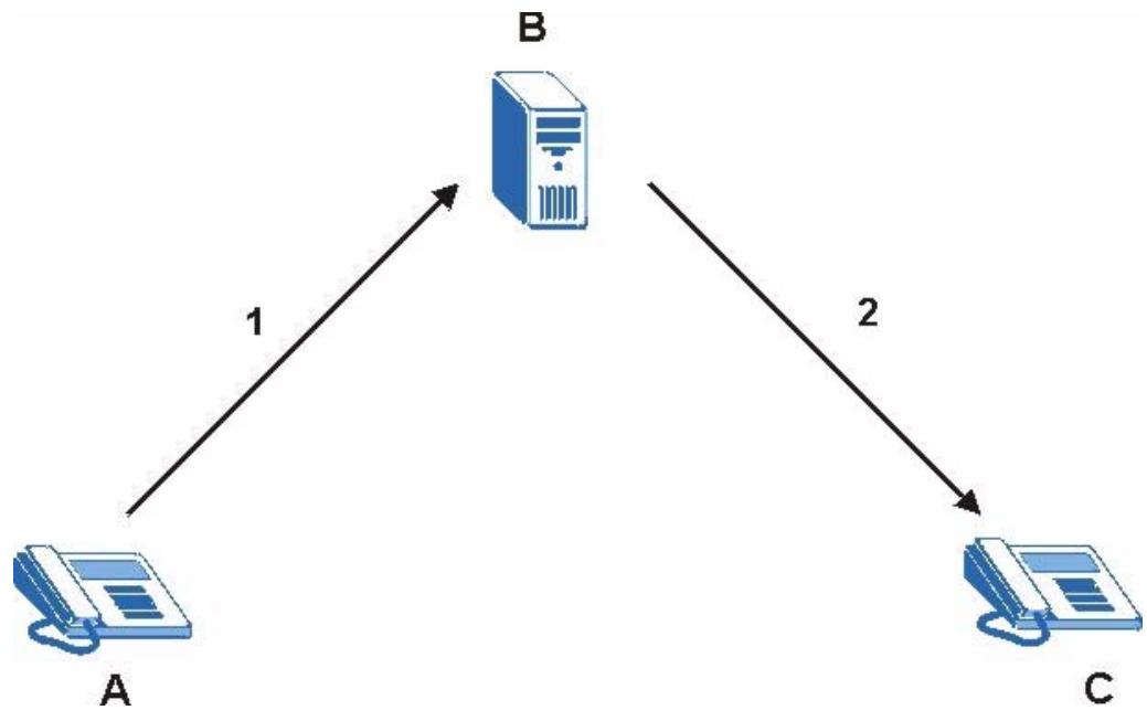
Figure 129 SIP Proxy Server
14.1.4.3 SIP Redirect Server
A SIP redirect server accepts SIP requests, translates the destination address to an IP address and sends the translated IP address back to the device that sent the request. Then the client device that originally sent the request can send requests to the IP address that it received back from the redirect server. Redirect servers do not initiate SIP requests.
In the following example, you want to use client device A to call someone who is using client device C.
1 Client device A sends a call invitation for C to the SIP redirect server (B).
2 The SIP redirect server sends the invitation back to A with C's IP address (or domain name).
3 Client device A then sends the call invitation to client device C.
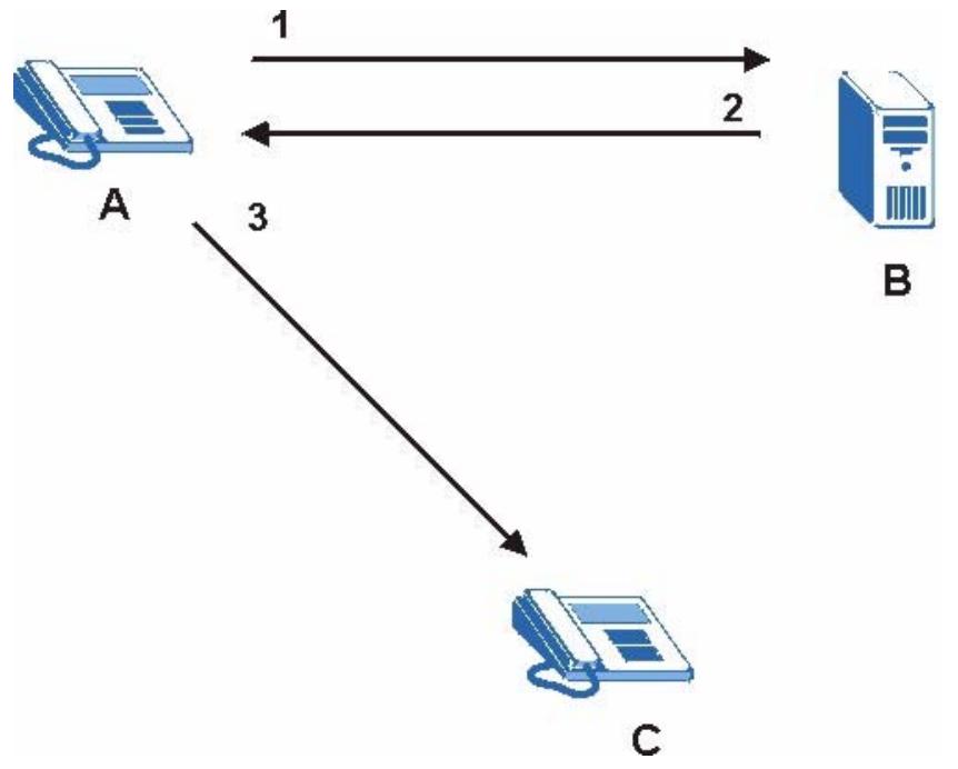
Figure 130 SIP Redirect Server
14.1.4.4 SIP Register Server
A SIP register server (also known as a registrar server) maintains a database of SIP identity-to-IP address (or domain name) mapping. The register server checks your user name and password when you register.
14.1.5 RTP
When you make a VoIP call using SIP, the RTP (Real time Transport Protocol) is used to handle voice data transfer. See RFC 1889 for details on RTP.
14.1.6 NAT and SIP
NAT (Network Address Translation - NAT, RFC 1631) is the translation of the IP address of a host in a packet, for example, the source address of an outgoing packet, used within one network to a different IP address known within another network.
The V630 must register its public IP address with a SIP register server. If there is a NAT router between the V630 and the SIP register server, the V630 probably has a private IP address. The V630 lists its IP address in the SIP message that it sends to the SIP register server. NAT does not translate this IP address in the SIP message. The SIP register server gets the V630's IP address from inside the SIP message and maps it to your SIP identity. If the V630 has a private IP address listed in the SIP message, the SIP server cannot map it to your SIP identity.
Use STUN or outbound proxy to allow the V630 to list its public IP address in the SIP messages.
14.1.6.1 STUN
STUN (Simple Traversal of User Datagram Protocol (UDP) through Network Address Translators) allows the V630 to find the presence and types of NAT routers and/or firewalls between it and the public Internet. STUN also allows the V630 to find the public IP address that NAT assigned, so the V630 can embed it in the SIP data stream. STUN does not work with symmetric NAT routers or firewalls. See RFC 3489 for details on STUN.
The following figure shows how STUN works.
1 The V630 (A) sends SIP packets to the STUN server (B).
2 The STUN server (B) finds the public IP address and port number that the NAT router used on the V630's SIP packets and sends them to the V630.
3 The V630 uses the public IP address and port number in the SIP packets that it sends to the SIP server (C).
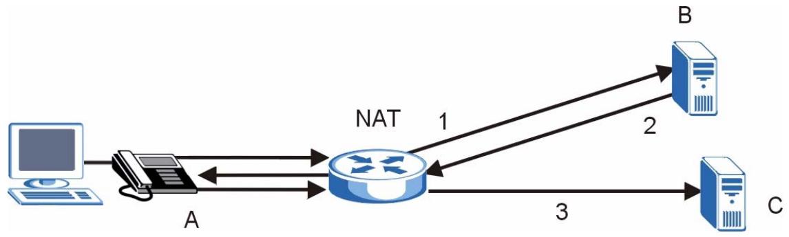
Figure 131 STUN
14.1.6.2 Outbound Proxy
Your VoIP service provider may host a SIP outbound proxy server to handle all of the V630's VoIP traffic. This allows the V630 to work with any type of NAT router and eliminates the need for STUN or a SIP ALG. Turn off a SIP ALG on a NAT router in front of the V630 to keep it from retranslating the IP address (since this is already handled by the outbound proxy server).
14.1.7 Voice Coding
A codec (coder/decoder) codes analog voice signals into digital signals and decodes the digital signals back into voice signals. The V630 supports the following codecs.
- G.711 is a Pulse Code Modulation (PCM) waveform codec. PCM measures analog signal amplitudes at regular time intervals (sampling) and converts them into digital bits (quantization). Quantization "reads" the analog signal and then "writes" it to the nearest digital value. For this reason, a digital sample is usually slightly different from its analog original (this difference is known as "quantization noise").
-
G.726 is an ADPCM waveform codec that uses a lower bit rate than standard PCM conversion. G.726 operates at 16, 24, 32 or 40 kbps.
-
G.729 is an Analysis-by-Synthesis (AbS) hybrid waveform codec that uses a filter based on information about how the human vocal tract produces sounds. The codec analyzes the incoming voice signal and attempts to synthesize it using its list of voice elements. It tests the synthesized signal against the original and, if it is acceptable, transmits details of the voice elements it used to make the synthesis. Because the codec at the receiving end has the same list, it can exactly recreate the synthesized audio signal. G.729 provides good sound quality and reduces the required bandwidth to 8kbps.
14.2 SIP Settings Screen
Click SIP to open the following screen. Use this screen to maintain basic information about each SIP account. Your VoIP service provider (the company that lets you make phone calls over the Internet) should provide this.
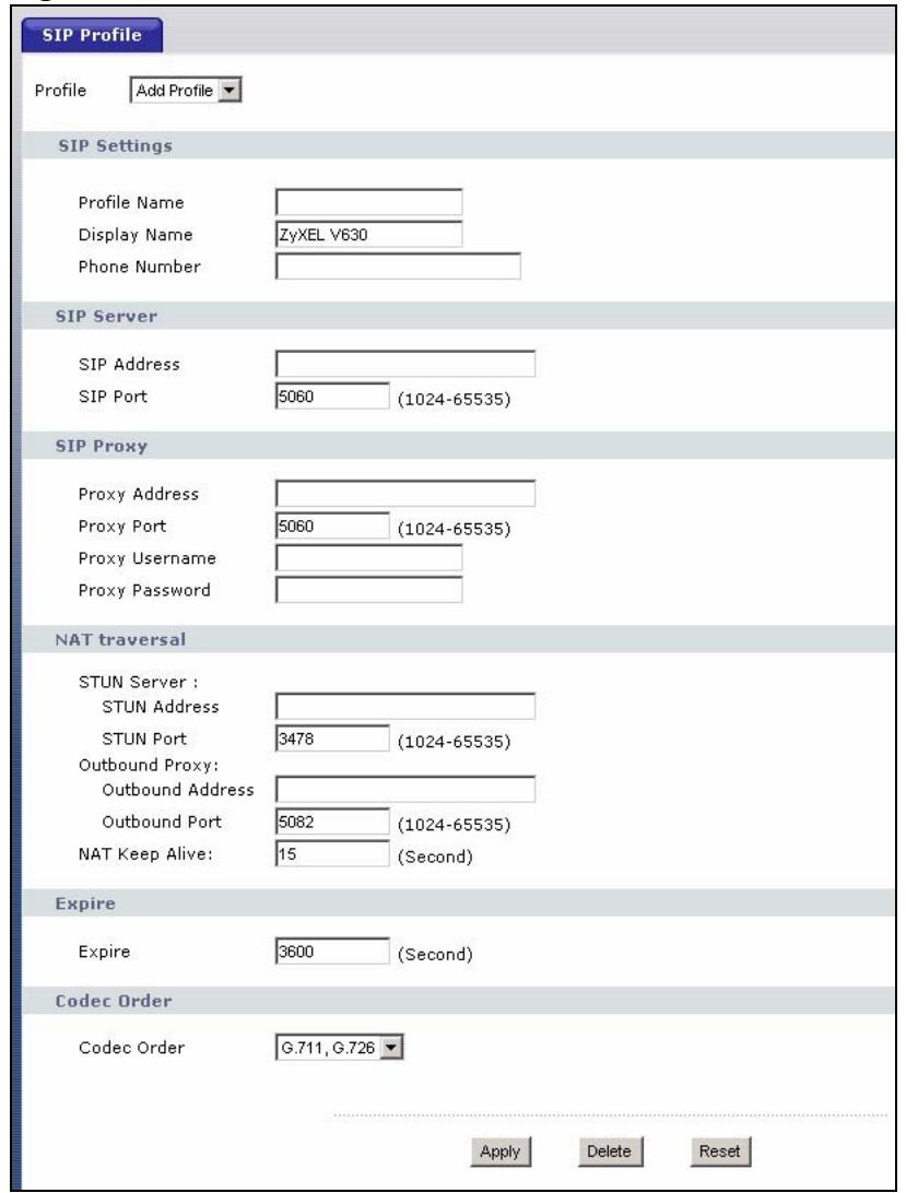
Figure 132 SIP
Each field is described in the following table.
Table 103 SIP
| LABEL | DESCRIPTION |
| Profile | Select a profile of SIP settings to edit or select Add Profile to create a new one. |
| SIP Settings | |
| Profile Name | Specify the name to use for the SIP account within the V630. |
| Display Name | Specify the profile name that you want to display on the LCD main screen when the SIP account is registered. |
| Active | Select this if you want the V630 to use this account. Clear it if you do not want the V630 to use this account. |
| Phone Number | Enter your SIP number. In the full SIP URI, this is the part before the @ symbol. You can use up to 50 printable English keyboard characters. |
| SIP Server | |
| SIP Address | Enter the IP address or domain name of the SIP server provided by your VoIP service provider. You can use up to 32 printable English keyboard characters. It does not matter whether the SIP server is a proxy, redirect or register server. |
| SIP Port | Enter the SIP server's listening port number, if your VoIP service provider gave you one. Otherwise, keep the default value. |
| SIP Proxy | |
| Proxy Address | If the VoIP service provider provided a SIP proxy server address, select this to configure it. If you have more than one server's address, use this menu to enter the registrar server's address. |
| Proxy Port | If the VoIP service provider provided a port number other than 5060, select this to configure it. |
| ProxyUsername | Enter the user name for registering this SIP account, exactly as it was given to you. |
| ProxyPassword | Enter the user name for registering this SIP account, exactly as it was given to you. |
| NAT traversal | NAT traversal deals with problems SIP has going through NAT. |
| STUN Server | Configure the STUN server fields if all of the following conditions are satisfied. • There is a NAT router between the V630 and the SIP server. • The NAT router is not a SIP ALG. • Your VoIP service provider gave you an IP address or domain name for a STUN server. |
| STUN Address | Enter the IP address or domain name of the STUN server provided by your VoIP service provider. |
| STUN Port | Enter the STUN server's listening port, if your VoIP service provider gave you one. Otherwise, keep the default value. |
| Outbound Proxy | Configure the outbound proxy fields if your service provider has a SIP outbound server to handle voice calls. This allows the V630 to work with any type of NAT router and eliminates the need for STUN or a SIP ALG. Turn off any SIP ALG on a NAT router in front of the V630 to keep it from retranslating the IP address (since this is already handled by the outbound proxy server. |
| Outbound address | Enter the IP address or domain name of the SIP outbound proxy server. |
| Outbound Port | Enter the outbound proxy server's listening port, if your VoIP service provider gave you one. Otherwise, keep the default value. |
Table 103 SIP
| LABEL | DESCRIPTION |
| NAT Keep Alive | Use NAT keep alive to stop NAT routers between the V630 and SIP server (a SIP proxy server or outbound proxy server) from dropping the SIP session. The V630 does this by sending SIP notify messages to the SIP server based on the specified interval. Enter how often (in seconds) the V630 should send SIP notify messages to the SIP server. |
| Expire | Enter the number of seconds your SIP account is registered with the SIP register server before it is deleted. The V630 automatically tries to re-register your SIP account when one-half of this time has passed. (The SIP register server might have a different expiration.) |
| Codec Order | Select the type of voice coder/decoder (codec) that you want the V630 to attempt to use first. • G.711 provides high voice quality but requires more bandwidth (64 kbps). • G.726 operates at 16, 24, 32 or 40 kbps. • G.729 operates at 8 kbps. The V630 must use the same codec as the peer. When two SIP devices start a SIP session, they must agree on a codec. |
| Apply | Click Apply to save your changes back to the V630. |
| Delete | Click Delete to remove the profile. |
| Reset | Click Reset to return the screen to the most recently saved settings. |
Auto Provision
Use the Auto Provision screen to set the V630 to use an auto-provisioning server.
15.1 Auto Provision Screen
Click Auto Provision to open the following screen.
If there is an auto-provisioning server on the network, use this screen to configure the V630 to use it. When auto-provisioning is used, the V630 downloads SIP settings automatically from the auto-provisioning server, meaning you do not have to input them manually.
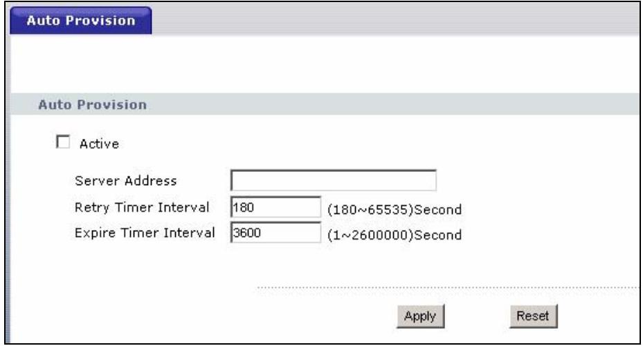
Figure 133 Auto Provision
The following table describes the labels in this screen.
Table 104 Auto Provision
| LABEL | DESCRIPTION |
| Active | Select this to set the V630 to request and receive auto-provisioning files. |
| Server Address | Enter the auto provisioning server's IP address. |
| Port | Enter the auto-provisioning server's port number. |
| Retry Timer Interval | Select this to see or edit how long the V630 waits, if it requests an auto-provisioning file but does not receive one, before requesting the file again. |
| Expire Timer Interval | Select this to see or edit how long the V630 waits after it successfully receives an auto-provisioning file before it requests another. |
| Select | Press this to choose the highlighted entry in the menu. |
Table 104 Auto Provision
| LABEL | DESCRIPTION |
| Apply | Click Apply to save your changes back to the V630. |
| Reset | Click Reset to return the screen to the most recently saved settings. |
PART IV
System,
Troubleshooting, and Specifications
System (139)
Troubleshooting (141)
Product Specifications (147)
Use the System screens to change the V630's passwords, display information, or upload firmware.
16.1 Password Screen
Click System > Change Password to open the following screen. Use this screen to change the web configurator login password.
- Use the Basic tab to configure the user login password.
- Use the System tab to configure the administrator login password.

If you forget your password you will need to reset the device. See your Quick Start Guide for details.
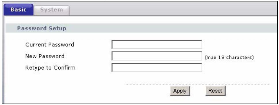
Figure 134 System > Change Password
The following table describes the labels in this screen.
Table 105 System > Password
| LABEL | DESCRIPTION |
| Password Setup | |
| Current Password | Type in the existing password (“1234” is the default password). |
| New Password | Type the new password. Note that as you type a password, the screen displays an asterisk (*) for each character you type. |
| Retype to Confirm | Retype your new system password for confirmation. |
| Apply | Click this to save your changes back to the device. |
| Reset | Click this to return the screen to the most recently saved settings. |
Use the System > Information screen to see the current status of the V630, its system resources, and current TCP/IP, WLAN, and SIP settings. See Chapter 10 on page 115 for details.
Click System > Upgrade FW.
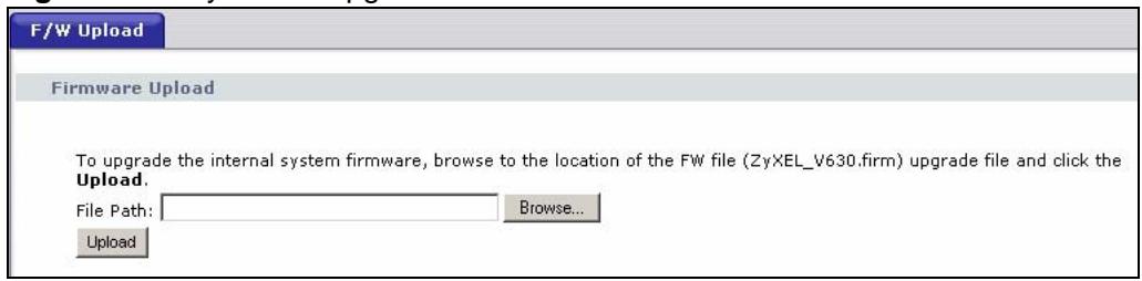
Figure 135 System > Upgrade FW
The following table describes the labels in this screen. The V630 automatically restarts.
System > Information
Troubleshooting
This chapter offers some suggestions to solve problems you might encounter. The potential problems are divided into the following categories.
- Power, Hardware Connections, and LEDs
V630 Web Configurator Access and Login
Phone Calls
17.1 Power, Hardware Connections, and LEDs

The V630 does not turn on.
1 Make sure you have the battery installed and charged.
2 If you need to charge the battery make sure the appropriate power adaptor or cord is connected to the V630 and plugged in to an appropriate power source. Make sure the power source is turned on.
3 If charging does not help, remove the battery and reinstall it. Make sure the charger/USB cable is unplugged and remove the battery cover. Then pull the battery's plastic tab and lift the battery out. See the Quick Start Guide for how to install the battery.
The contacts (the metal parts) on the battery or the V630 may be dirty or corroded. Clean them.

Do not use liquid of any kind to clean the battery or the V630.
4 If the problem continues, contact the vendor.

A key or LED does not behave as expected.
1 Make sure you understand the normal behavior of the key or LED. See the Quick Start Guide.
2 Make sure the keypad is unlocked. Press # and the Left key to unlock it.
17.2 V630 Web Configurator Access and Login

I forgot the IP address for the V630.
1 Check the IP address the V630 is using in the Setup > Information > TCP/IP LCD menu.
2 Set a static IP address for the V630 in the Network > WLAN Profiles > Profiles List > Edit > IP Setting menus (see Section 6.12 on page 76).

I forgot the password.
1 The default user password is password. The default administrator password is admin.
2 If this does not work, you have to reset the device to its factory defaults. See Section 5.18 on page 59.

I cannot see or access the Login screen in the web configurator.
1 Before you can access the web configurator, you must enable it in the Menu > Setup > Phone Setting > Web Configurator LCD menu.
2 Make sure you are using the correct IP address.
- Check the IP address the V630 is using in the Setup > Information > TCP/IP LCD menu.
- If you changed the IP address (Section 16.1 on page 139), use the new IP address.
3 Check that the phone is on and connected to an AP. You should see the wireless signal icon.
4 Make sure your Internet browser does not block pop-up windows and has JavaScript and Java enabled. See Appendix C on page 189.
5 Make sure your computer is in the same subnet as the V630. See Appendix A on page 153 and Appendix D on page 197. (If you know that there are routers between your computer and the V630, skip this step.)
6 If the problem continues, contact the network administrator or vendor.

I can see the Login screen, but I cannot log in to the V630.
1 Make sure you have entered the user name and password correctly. The default password is 1234. This field is case-sensitive, so make sure [Caps Lock] is not on.
2 Close your browser session and open a new one. You may also need to clear your Internet browser's cache. In Internet Explorer, click Tools and then Internet Options to open the Internet Options screen.
In the General tab, click Delete Files. In the pop-up window, select the Delete all offline content check box and click OK. Click OK in the Internet Options screen to close it.
3 Turn the phone off and on again.
17.3 Wireless LAN

When I scan for an access point I can't find one, or I can't find the right one.
If you scan for an access point (AP) and find none, either the V630 is out of the AP's coverage area (out of range), or the AP is set to not broadcast its SSID (the network name). Move closer to the AP and try again.
If the AP still does not show on the scan result, either:
- Input the ESSID manually and try to connect.
- Access the AP's configuration interface and set it to broadcast the SSID.
If other APs display when you scan, the V630 is working correctly. However, if you know that there are other APs in the area, and no APs display when you scan, you may have a hardware problem. In this case, contact your vendor.

I can't connect to the access point.
If you find the AP when you scan, but you cannot connect to it, there may be a problem with the wireless security settings.
- Ensure that the V630 supports the security standard the AP uses.
- Ensure that the V630 and the AP use exactly the same settings.
- If you continue to experience difficulties, set the AP to use no security (disconnect it from the network first) and try to connect.
- If you have another wireless client (a notebook wireless card, for example) try using it to connect. If it connects successfully, your V630 may have a hardware problem. Contact your vendor. If the other wireless client does not connect successfully, the AP may be malfunctioning or misconfigured.
17.4 Phone Calls

I cannot make calls.
Ensure that your V630 is set up as shown in your Quick Start Guide.
Look at the LCD screen. You should see the signal strength icon. If a SIP account is registered, the name of its profile appears in the main screen. If a SIP account is not registered, No SIP Service displays.
If no SIP account is registered, do the following.
1 The V630's SIP settings may be misconfigured. Check your SIP settings and re-enter them if necessary (see Section 6.21 on page 81 for details).
2 If No SIP Service still displays, check your network settings (see Section 6.7 on page 72). If they are not correct, change them using information supplied by your ISP or network administrator. If this does not help, contact your ISP or network administrator.
If a SIP account is registered, try to make a call. If you still cannot call out, do the following.
1 Check your DNS (Domain Name Service) settings (see Section 5.27 on page 64).
- If you use a static IP address, see Section 6.13 on page 76 for how to change DNS settings.
- If you use a dynamic IP address (DHCP) your DNS settings are controlled by the DHCP server. The DHCP server may belong to your service provider, or it may be on your network. If your V630 does not get DNS server information automatically, check the settings on the AP to which the V630 is connected, or contact your ISP or network administrator.
- If you use PPPoE, your DNS settings are controlled by your Internet Service Provider. If your V630 does not get DNS server information automatically, contact your ISP.
2 Make sure that your V630 uses the voice codecs that the callee's device supports.

I can make some calls, but not others.
The V630's DNS (Domain Name Service) settings may be misconfigured. See the suggestions about DNS in the troubleshooting section for "I cannot make calls".
If this does not help, the phone of the person you are calling may be malfunctioning or misconfigured.

My phone service works for a while and then cuts off and the V630 has to re-register.

The SIP server's expiration time is how long an entry remains registered with the SIP server. After the time period expires, the SIP register server deletes the V630's entry from the database of registered SIP numbers. Different register servers may use different time periods. You may need to configure a shorter time in the Expire menu. See Section 6.40 on page 93.
I can make phone calls, but I cannot receive them.
Check your V630's call forwarding settings (see Section 5.19 on page 60). If they are misconfigured, certain calls may be mistakenly forwarded.

My calls are of poor audio quality.
1 The Wireless LAN signal may be weak. Move closer to the access point, and away from potential sources of radio interference (such as microwave ovens, electric motors and other radio frequency emitting devices). If you have more than one access point, scan for and connect to the one with the stronger signal.
2 If your V630 is connected to a router with configurable bandwidth management settings, check these settings. Consult the router's documentation for more information.
3 Your V630 may be set to use a voice codec (audio coder / decoder) that does not provide optimal sound quality. See Section 6.41 on page 93 and check with your VoIP service provider to find out the CODECs you should use.
4 Your VoIP service provider may be using settings that reduce voice quality in order to conserve bandwidth. You may need to subscribe to a different calling plan to get better call quality.
5 The VoIP service's channels may all be full. Wait a short time and try again.
6 If call quality is always poor when you call certain phone numbers, the other person's connection may be at fault.

I cannot use some calling features.
Some features your V630 supports depend on your VoIP service provider. You may have to subscribe to certain services. Contact your VoIP service provider for more information.

The incoming or outgoing audio is too quiet or too loud.
During a call, press the Up or Down key to adjust the volume.

I cannot hear the V630's ring when a call is incoming.
You can configure the ring volume in the LCD menus. See Section 4.7 on page 46.
Product Specifications
The following tables summarize the V630's hardware and firmware features.
Table 106 Hardware Specifications
| Dimensions (L x W x D) | 105 mm x 45 mm x 20 mm |
| Weight | 75 g (including the battery) |
| Power Adaptor Specification | 100~240 V AC 50/60 Hz .15A input 5.0 V 600 mA output |
| Ports | USB |
| LCD Screen | 1.5" mono-chrome 96 by 64 pixel |
| (Headset) Microphone Port | 3.5mm |
| Antenna | Embedded PIFA antenna, 3.8 dBi peak gain |
| (Headset) Headphone Port | 3.5 mm |
| Operating Temperature | 0~40 C |
| Storage Temperature | -30~60 C |
| Operating Humidity | 10~95 % |
| Storage Humidity | 10~95 % |
| Speakerphone | Internal speaker and microphone. |
| Phone Functions | Call forwarding Call transferring Conference calling Voice mail indicator Call muting Phonebook |
| RADIO SPECIFICATIONS | |
| Communications Standards | IEEE 802.11b IEEE 802.11g |
| Frequency | IEEE 802.11b/g: Industrial Scientific Medical Band United States (FCC): 2.412 ~ 2.462 GHz Japan (ARIB): 2.412 ~ 2.472 GHz Europe (ETSI): 2.412 ~ 2.472 GHz |
| IEEE 802.1b/g Operating Channels | North American and Taiwan: 11 Europe: 13 |
Table 106 Hardware Specifications
| IEEE 802.1b/g Data Rate | IEEE 802.11b: 11Mbps with automatic fallback to 5.5, 2, 1 Mbps IEEE 802.11g: 54Mbps with automatic fallback to 48, 36, 24, 18, 12, 9, 6 Mbps |
| Modulation | IEEE 802.11b: CCK (11 and 5.5 Mbps), DQPSK (2 Mbps) and DBPSK (1 Mbps) IEEE 802.11g: OFDM with BPSK, QPSK and 16/64-QAM sub-Carrier modulations |
| Maximum Output Power | Tolerance: +/- 1.5 dBm IEEE 802.11b: 15 dBm at 11/5.5/2/1 Mbps IEEE 802.11g: 13 dBm at 54 Mbps |
| RX Sensitivity | Tolerance: +/- 1 dBm IEEE 802.11b: -80 dBm at 11 Mbps IEEE 802.11g: -65 dBm at 54 Mbps |
Table 107 Firmware Specifications
| FEATURE | DESCRIPTION |
| Default IP Setting | DHCP client |
| Default User Password | password |
| Default Administrator Password | admin |
| Device Management | Use the V630's LCD screen menus or the web configurator to easily configure the rich range of features. |
| Firmware Upgrade | Download new firmware (when available) from the ZyXEL web site and use the web configurator to put it on the V630.Note: Only upload firmware for your specific model! |
| Number of Wireless Profiles | Up to 10 configurable. |
| Number of SIP Profiles | Up to 10 configurable. |
| Phonebook | Up to 200 contacts |
| Call History | Up to 30 records (including called, missed, and received calls). |
| Time and Date | Get the current time and date from an external server when you turn on your V630. You can also set the time manually. These dates and times are then used in logs. |
| Logs | Use logs for troubleshooting. |
| PPPoE | PPPoE mimics a dial-up Internet access connection. |
| Auto-provisioning support | When auto-provisioning is used, the V630 downloads SIP settings automatically from the auto-provisioning server, meaning you do not have to input them manually. |
| Dynamic Jitter Buffer | The built-in adaptive buffer helps to smooth out the variations in delay (jitter) for voice traffic. This helps ensure good voice quality for your conversations. |
| Voice Activity Detection/ Silence Suppression | Voice Activity Detection (VAD) reduces the bandwidth that a call uses by not transmitting when you are not speaking. |
Table 107 Firmware Specifications
| FEATURE | DESCRIPTION |
| Comfort Noise Generation | Your device generates background noise to fill moments of silence when the other device in a call stops transmitting because the other party is not speaking (as total silence could easily be mistaken for a lost connection). |
| Echo Cancellation | You device supports G.168, an ITU-T standard for eliminating the echo caused by the sound of your voice reverberating in the telephone receiver while you talk. |
| QoS (Quality of Service) | Quality of Service (QoS) mechanisms help to provide better service on a per-flow basis. Your device supports Type of Service (ToS) tagging. This allows the device to tag voice frames so they can be prioritized over the network. |
| Voice Codec | G.711 (64 kbps), G.726 (16/24/32/40 kbps), G.729 (8 kbps) |
| DTMF | Out-of-band (RFC2833) |
The following list, which is not exhaustive, illustrates the standards supported in the V630.
Table 108 Standards Supported
| STANDARD | DESCRIPTION |
| RFC 1305 | Network Time Protocol (NTP version 3) |
| RFC 1321 | The MD5 Message-Digest Algorithm |
| RFC 1661 | The Point-to-Point Protocol (PPP) |
| RFC 2327 | SDP: Session Description Protocol. |
| RFC 2516 | A Method for Transmitting PPP Over Ethernet (PPPoE) |
| RFC 2833 | RTP Payload for DTMF Digits, Telephony Tones and Telephony Signals |
| RFC 2976 | The SIP INFO Method |
| RFC 3261 | SIP: Session Initiation Protocol. (Updated by RFC3265, RFC3853) |
| RFC 3262 | Reliability of Provisional Responses in Session Initiation |
| RFC 3263 | Session Initiation Protocol (SIP): Locating SIP Servers. |
| RFC 3264 | An Offer/Answer Model with Session Description Protocol (SDP) |
| RFC 3311 | The Session Initiation Protocol (SIP) UPDATE Method |
| RFC 3323 | A Privacy Mechanism for the Session Initiation Protocol (SIP) |
| RFC 3325 | Private Extensions to the Session Initiation Protocol (SIP) for Asserted Identity within Trusted Networks |
| RFC 3389 | Real-time Transport Protocol (RTP) Payload for Comfort Noise (CN) |
| RFC 3420 | Internet Media Type message/sipfrag |
| RFC 3489 | STUN (Simple Traversal of User Datagram Protocol (UDP) through Network Address Translators) server. |
| RFC 3515 | The Session Initiation Protocol (SIP) Refer Method. |
| RFC 3550 | RTP: A Transport Protocol for Real-Time Applications. |
| RFC 3551 | RTP Profile for Audio and Video Conferences with Minimal Control |
| RFC 3581 | An Extension to the Session Initiation Protocol (SIP) for Symmetric Response Routing. |
| RFC 3665 | Session Initiation Protocol (SIP) Basic Call Flow Examples |
| RFC 3842 | A Message Summary and Message Waiting Indication Event Package for the Session Initiation Protocol (SIP) |
| RFC 3891 | The Session Initiation Protocol (SIP) "Replaces" Header |
| RFC 3911 | The Session Initiation Protocol (SIP) ``Join" Header |
| RFC 4028 | Session Timers in the Session Initiation Protocol (SIP) |
PART V
Appendices and Index
Setting Up Your Computer's IP Address (153)
Pop-up Windows, JavaScript and Java Permissions (189)
IP Addresses and Subnetting (197)
Legal Information (207)
Customer Support (211)
Index (217)
Setting Up Your Computer's IP Address

Your specific ZyXEL device may not support all of the operating systems described in this appendix. See the product specifications for more information about which operating systems are supported.
This appendix shows you how to configure the IP settings on your computer in order for it to be able to communicate with the other devices on your network. Windows Vista/XP/2000, Mac OS 9/OS X, and all versions of UNIX/Linux include the software components you need to use TCP/IP on your computer.
If you manually assign IP information instead of using a dynamic IP, make sure that your network's computers have IP addresses that place them in the same subnet.
In this appendix, you can set up an IP address for:
- Windows XP/NT/2000 on page 154
- Windows Vista on page 157
Mac OS X: 10.3 and 10.4 on page 161
Mac OS X: 10.5 on page 164
Linux: Ubuntu 8 (GNOME) on page 167
Linux: openSUSE 10.3 (KDE) on page 171
Windows XP/NT/2000
The following example uses the default Windows XP display theme but can also apply to Windows 2000 and Windows NT.
1 Click Start > Control Panel.
Figure 136 Windows XP: Start Menu
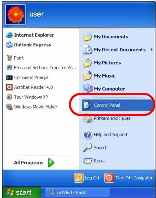
2 In the Control Panel, click the Network Connections icon.
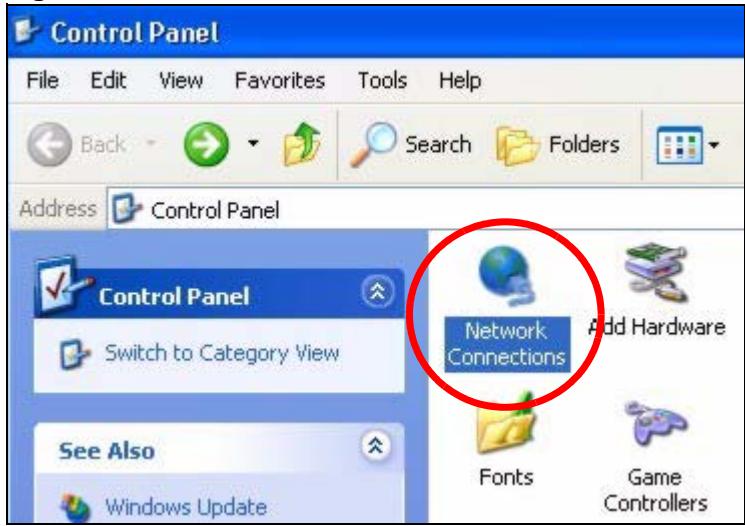
Figure 137 Windows XP: Control Panel
3 Right-click Local Area Connection and then select Properties.
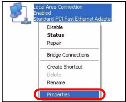
Figure 138 Windows XP: Control Panel > Network Connections > Properties
4 On the General tab, select Internet Protocol (TCP/IP) and then click Properties.
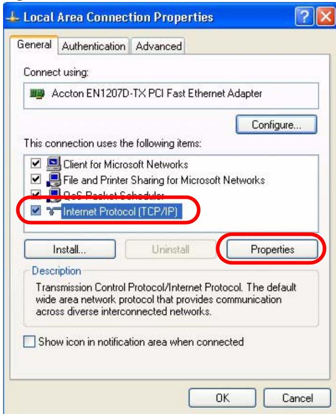
Figure 139 Windows XP: Local Area Connection Properties
5 The Internet Protocol TCP/IP Properties window opens.
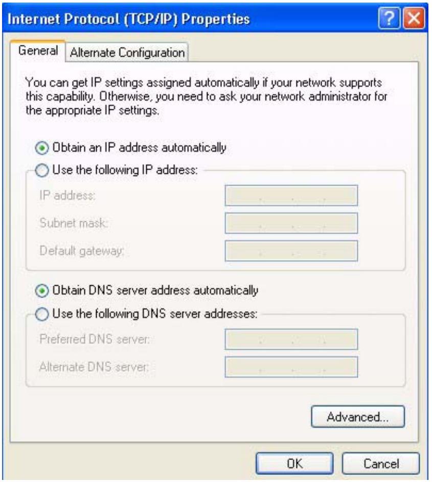
Figure 140 Windows XP: Internet Protocol (TCP/IP) Properties
6 Select Obtain an IP address automatically if your network administrator or ISP assigns your IP address dynamically.
Select Use the following IP Address and fill in the IP address, Subnet mask, and Default gateway fields if you have a static IP address that was assigned to you by your network administrator or ISP. You may also have to enter a Preferred DNS server and an Alternate DNS server, if that information was provided.
7 Click OK to close the Internet Protocol (TCP/IP) Properties window.
Click OK to close the Local Area Connection Properties window. Verifying Settings
1 Click Start > All Programs > Accessories > Command Prompt.
2 In the Command Prompt window, type "ipconfig" and then press [ENTER].
You can also go to Start > Control Panel > Network Connections, right-click a network connection, click Status and then click the Support tab to view your IP address and connection information.
Windows Vista
This section shows screens from Windows Vista Professional.
1 Click Start > Control Panel.
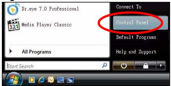
Figure 141 Windows Vista: Start Menu
2 In the Control Panel, click the Network and Internet icon.
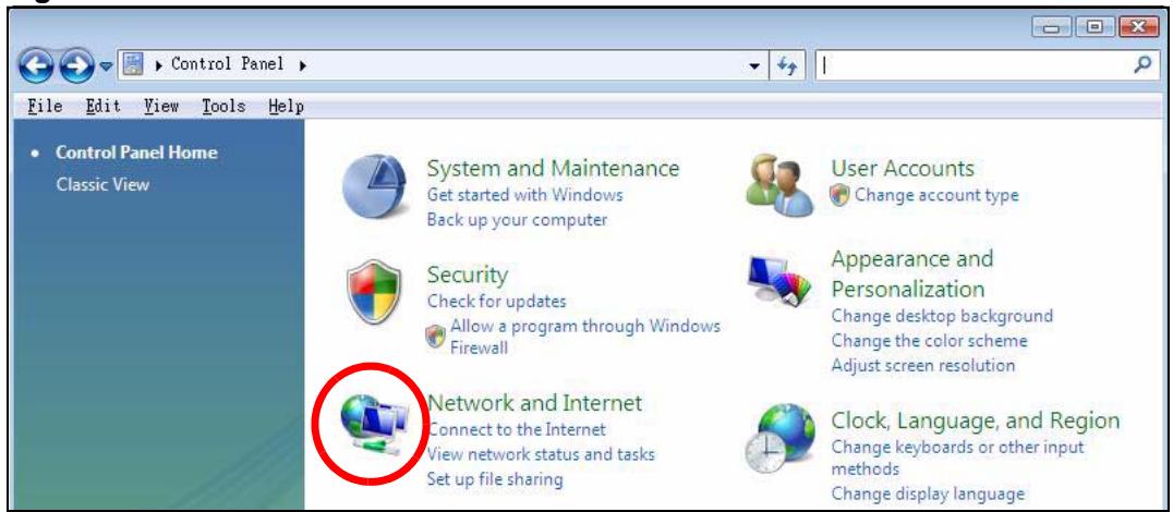
Figure 142 Windows Vista: Control Panel
3 Click the Network and Sharing Center icon.
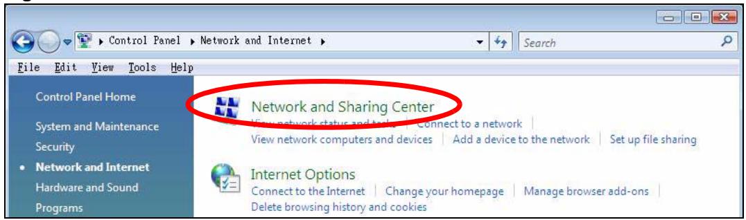
Figure 143 Windows Vista: Network And Internet
4 Click Manage network connections.
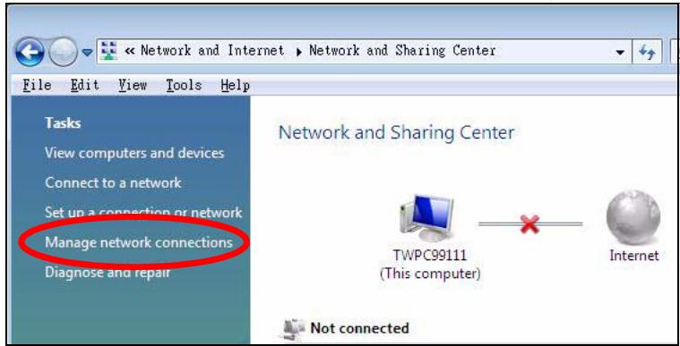
Figure 144 Windows Vista: Network and Sharing Center
5 Right-click Local Area Connection and then select Properties.
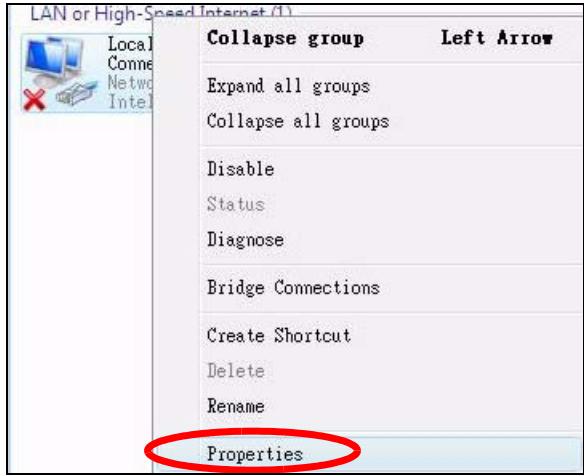
Figure 145 Windows Vista: Network and Sharing Center

During this procedure, click Continue whenever Windows displays a screen saying that it needs your permission to continue.
6 Select Internet Protocol Version 4 (TCP/IPv4) and then select Properties.
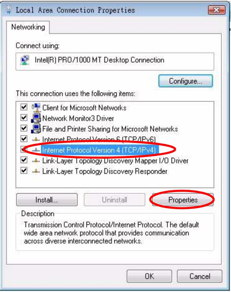
Figure 146 Windows Vista: Local Area Connection Properties
7 The Internet Protocol Version 4 (TCP/IPv4) Properties window opens.
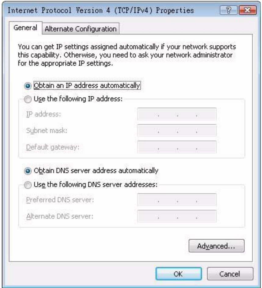
Figure 147 Windows Vista: Internet Protocol Version 4 (TCP/IPv4) Properties
8 Select Obtain an IP address automatically if your network administrator or ISP assigns your IP address dynamically.
Select Use the following IP Address and fill in the IP address, Subnet mask, and Default gateway fields if you have a static IP address that was assigned to you by your network administrator or ISP. You may also have to enter a Preferred DNS server and an Alternate DNS server, if that information was provided. Click Advanced.
9 Click OK to close the Internet Protocol (TCP/IP) Properties window.
Click OK to close the Local Area Connection Properties window. Verifying Settings
1 Click Start > All Programs > Accessories > Command Prompt.
2 In the Command Prompt window, type "ipconfig" and then press [ENTER].
You can also go to Start > Control Panel > Network Connections, right-click a network connection, click Status and then click the Support tab to view your IP address and connection information.
Mac OS X: 10.3 and 10.4
The screens in this section are from Mac OS X 10.4 but can also apply to 10.3.
1 Click Apple > System Preferences.
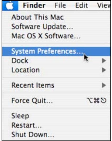
Figure 148 Mac OS X 10.4: Apple Menu
2 In the System Preferences window, click the Network icon.
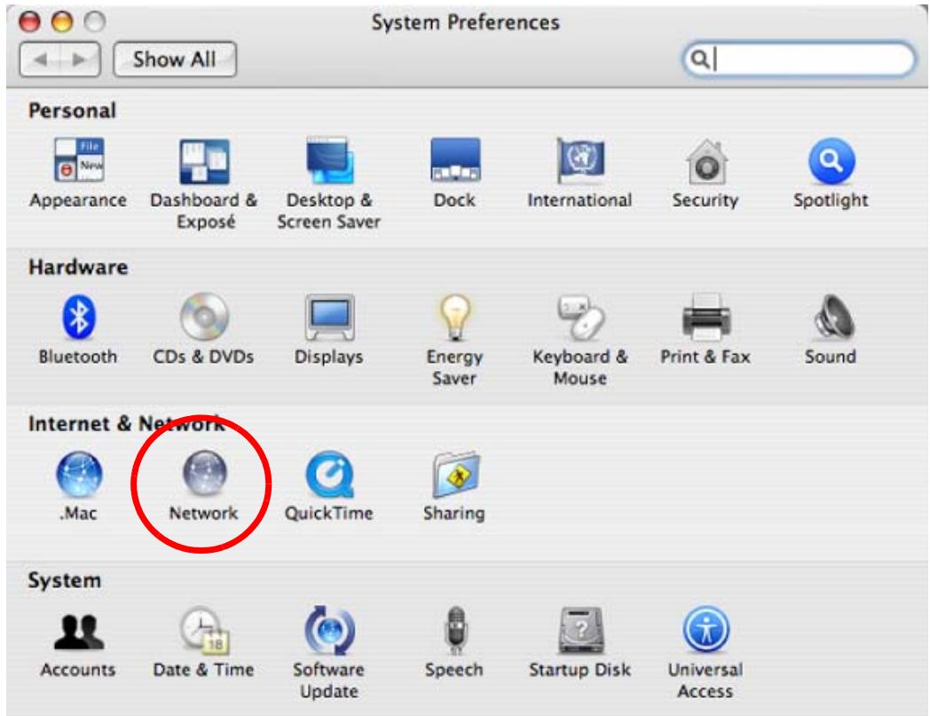
Figure 149 Mac OS X 10.4: System Preferences
3 When the Network preferences pane opens, select Built-in Ethernet from the network connection type list, and then click Configure.
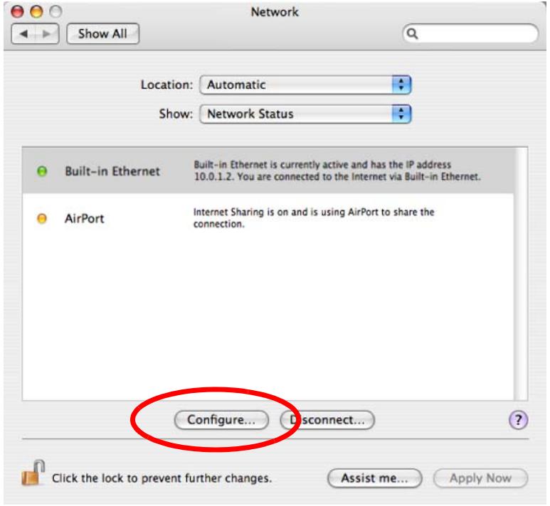
Figure 150 Mac OS X 10.4: Network Preferences
4 For dynamically assigned settings, select Using DHCP from the Configure IPv4 list in the TCP/IP tab.
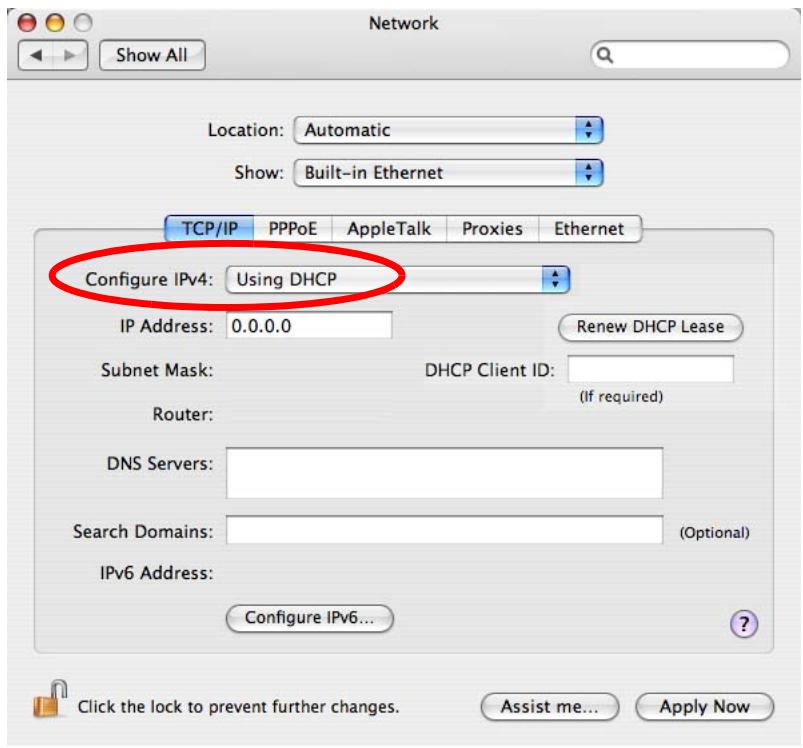
Figure 151 Mac OS X 10.4: Network Preferences > TCP/IP Tab.
5 For statically assigned settings, do the following:
From the Configure IPv4 list, select Manually.
- In the IP Address field, type your IP address.
- In the Subnet Mask field, type your subnet mask.
- In the Router field, type the IP address of your device.
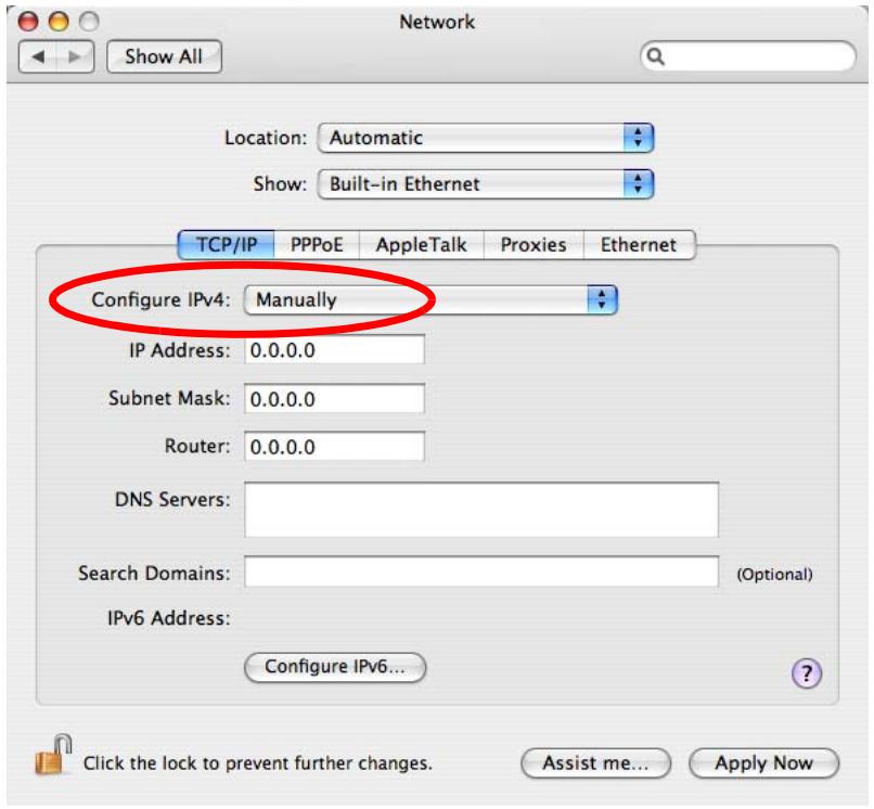
Figure 152 Mac OS X 10.4: Network Preferences > Ethernet
Click Apply Now and close the window. Verifying Settings
Check your TCP/IP properties by clicking Applications > Utilities > Network Utilities, and then selecting the appropriate Network Interface from the Info tab.
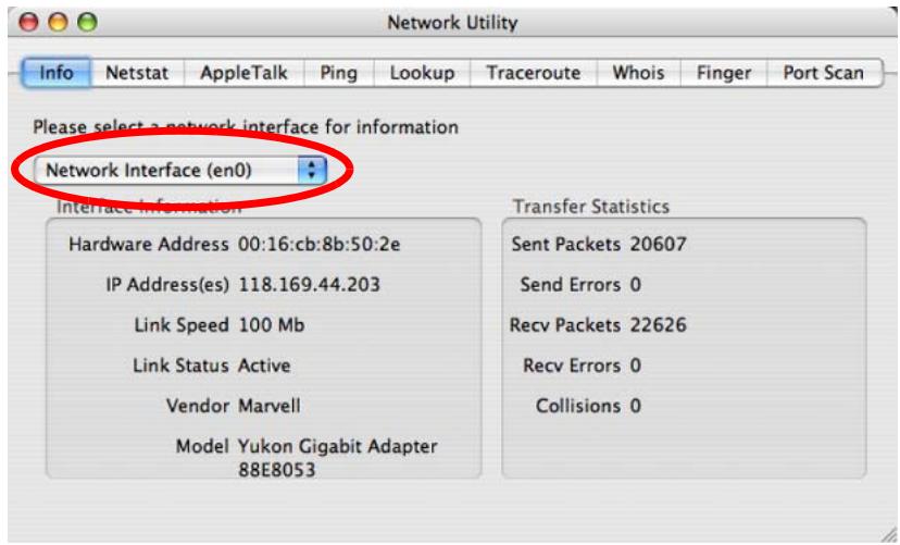
Figure 153 Mac OS X 10.4: Network Utility
Mac OS X: 10.5
The screens in this section are from Mac OS X 10.5.
1 Click Apple > System Preferences.
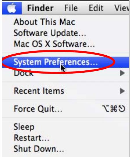
Figure 154 Mac OS X 10.5: Apple Menu
2 In System Preferences, click the Network icon.
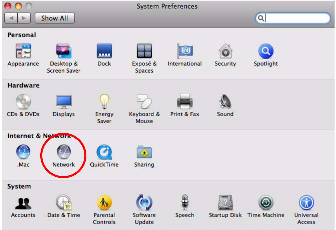
Figure 155 Mac OS X 10.5: Systems Preferences
3 When the Network preferences pane opens, select Ethernet from the list of available connection types.
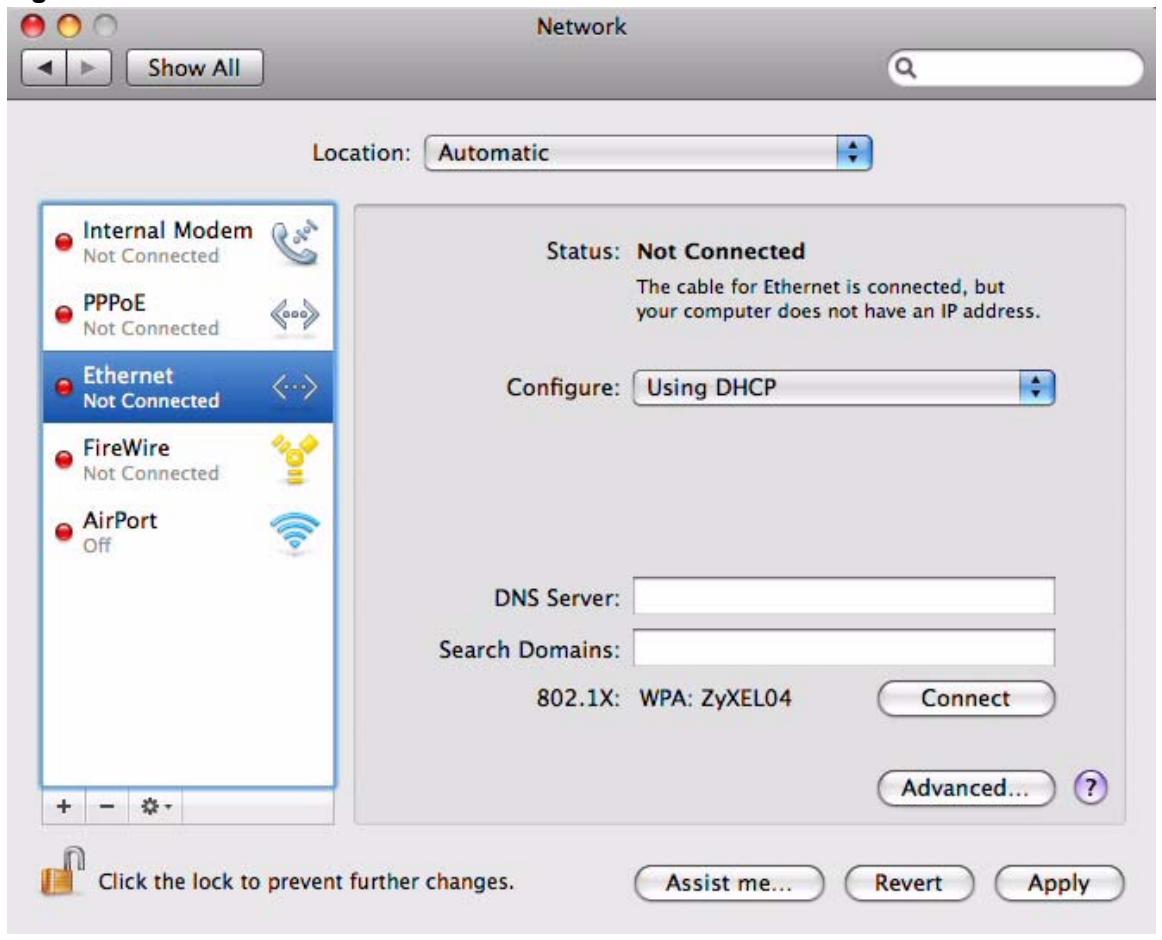
Figure 156 Mac OS X 10.5: Network Preferences > Ethernet
4 From the Configure list, select Using DHCP for dynamically assigned settings.
5 For statically assigned settings, do the following:
From the Configure list, select Manually.
- In the IP Address field, enter your IP address.
- In the Subnet Mask field, enter your subnet mask.
- In the Router field, enter the IP address of your V630.
Figure 157 Mac OS X 10.5: Network Preferences > Ethernet
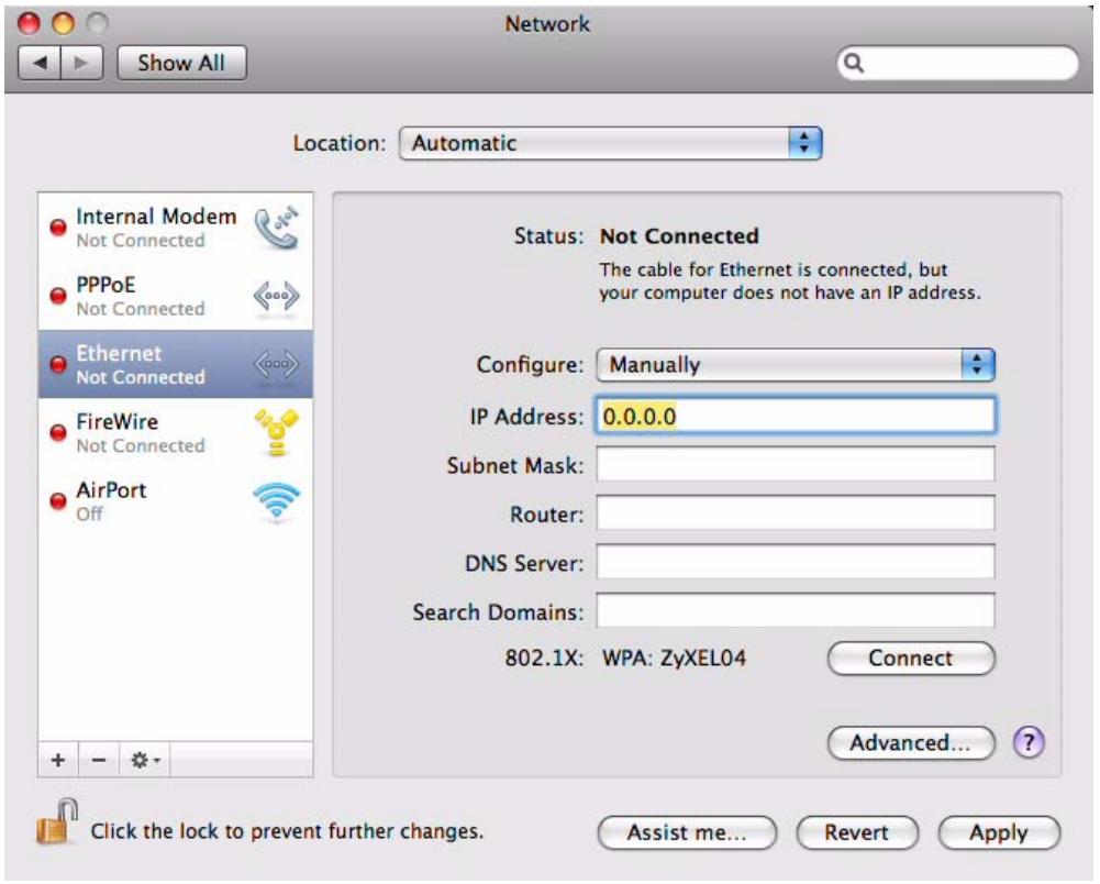
6 Click Apply and close the window.
Verifying Settings
Check your TCP/IP properties by clicking Applications > Utilities > Network Utilities, and then selecting the appropriate Network interface from the Info tab.
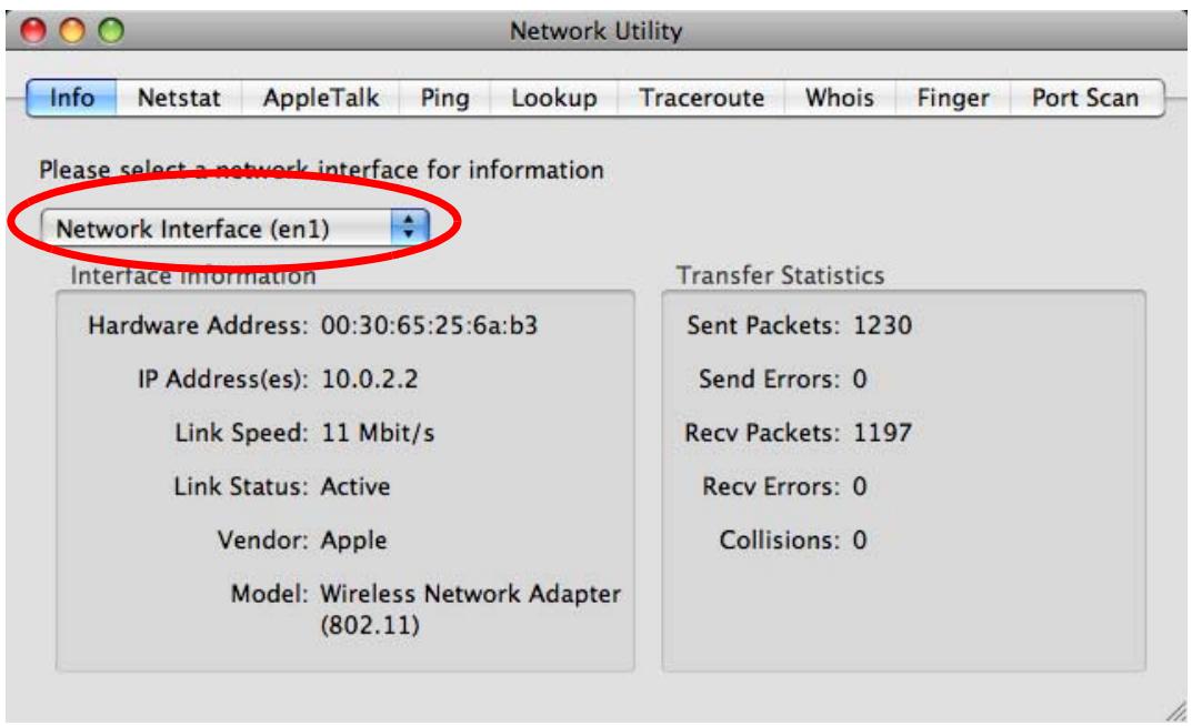
Figure 158 Mac OS X 10.5: Network Utility
Linux: Ubuntu 8 (GNOME)
This section shows you how to configure your computer's TCP/IP settings in the GNU Object Model Environment (GNOME) using the Ubuntu 8 Linux distribution. The procedure, screens and file locations may vary depending on your specific distribution, release version, and individual configuration. The following screens use the default Ubuntu 8 installation.

Make sure you are logged in as the root administrator.
Follow the steps below to configure your computer IP address in GNOME:
1 Click System > Administration > Network.
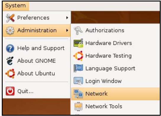
Figure 159 Ubuntu 8: System > Administration Menu
2 When the Network Settings window opens, click Unlock to open the Authenticate window. (By default, the Unlock button is greyed out until clicked.) You cannot make changes to your configuration unless you first enter your admin password.
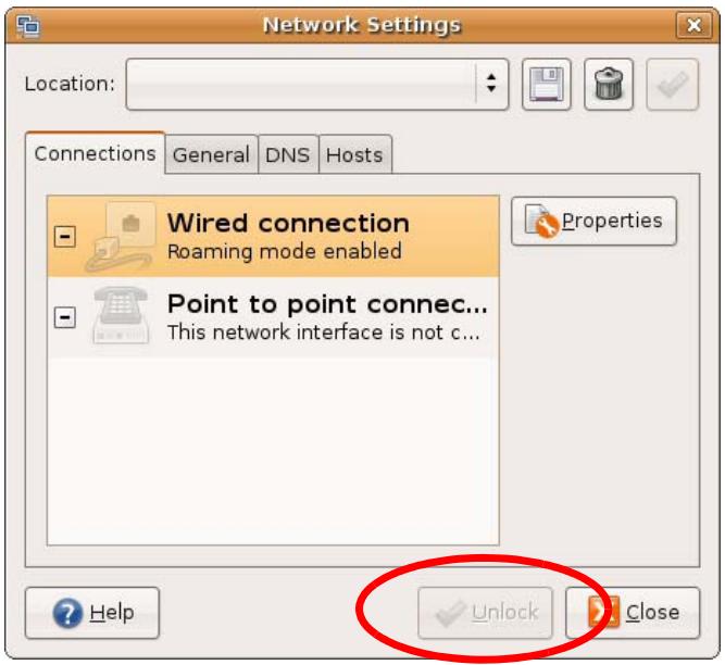
Figure 160 Ubuntu 8: Network Settings > Connections
3 In the Authenticate window, enter your admin account name and password then click the Authenticate button.
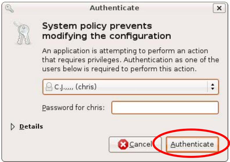
Figure 161 Ubuntu 8: Administrator Account Authentication
4 In the Network Settings window, select the connection that you want to configure, then click Properties.
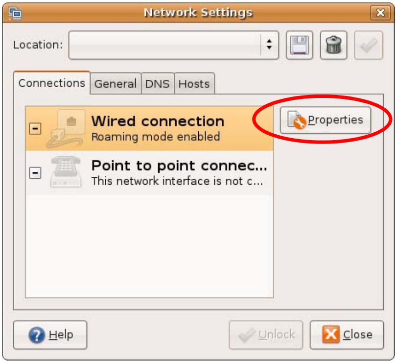
Figure 162 Ubuntu 8: Network Settings > Connections
5 The Properties dialog box opens.
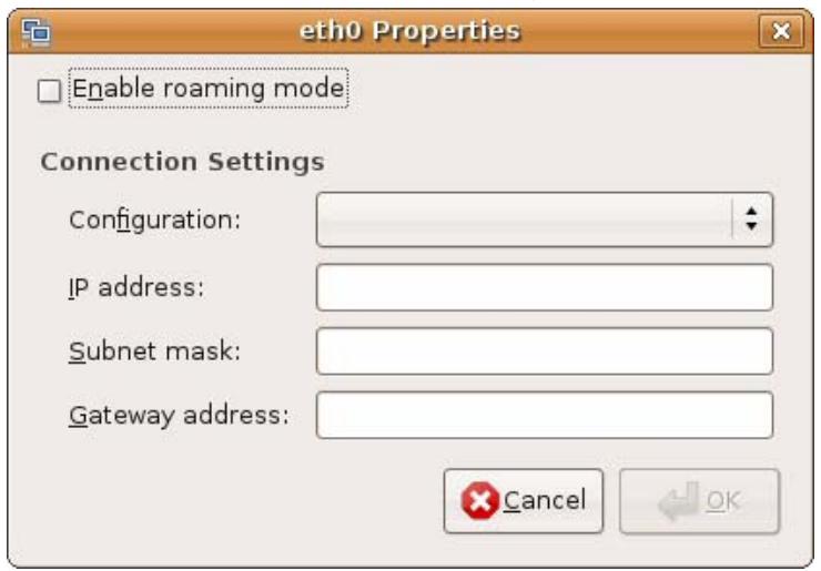
Figure 163 Ubuntu 8: Network Settings > Properties
- In the Configuration list, select Automatic Configuration (DHCP) if you have a dynamic IP address.
- In the Configuration list, select Static IP address if you have a static IP address. Fill in the IP address, Subnet mask, and Gateway address fields.
6 Click OK to save the changes and close the Properties dialog box and return to the Network Settings screen.
7 If you know your DNS server IP address(es), click the DNS tab in the Network Settings window and then enter the DNS server information in the fields provided.
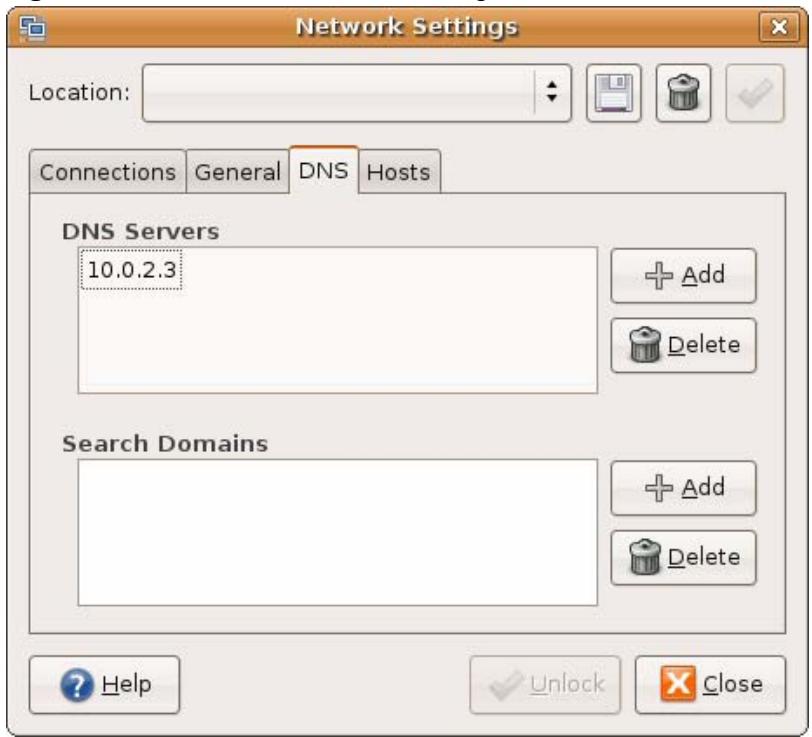
Figure 164 Ubuntu 8: Network Settings > DNS
8 Click the Close button to apply the changes.
Verifying Settings
Check your TCP/IP properties by clicking System > Administration > Network Tools, and then selecting the appropriate Network device from the Devices tab. The Interface Statistics column shows data if your connection is working properly.
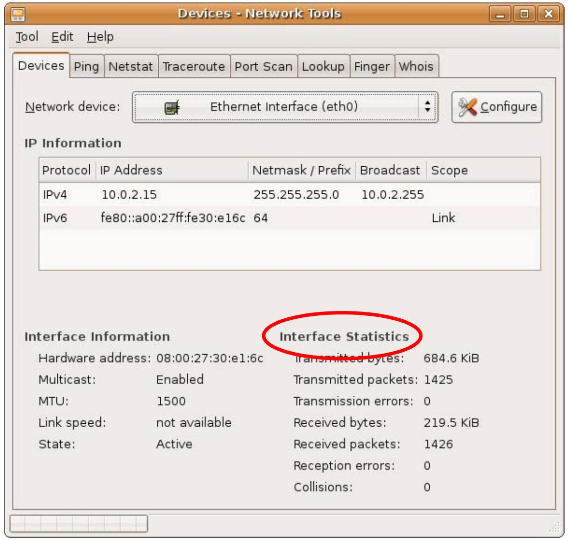
Figure 165 Ubuntu 8: Network Tools
Linux: openSUSE 10.3 (KDE)
This section shows you how to configure your computer's TCP/IP settings in the K Desktop Environment (KDE) using the openSUSE 10.3 Linux distribution. The procedure, screens and file locations may vary depending on your specific distribution, release version, and individual configuration. The following screens use the default openSUSE 10.3 installation.

Make sure you are logged in as the root administrator.
Follow the steps below to configure your computer IP address in the KDE:
1 Click K Menu > Computer > Administrator Settings (YaST).
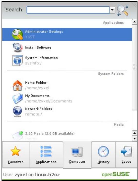
Figure 166 openSUSE 10.3: K Menu > Computer Menu
2 When the Run as Root - KDE su dialog opens, enter the admin password and click OK.
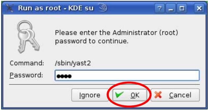
Figure 167 openSUSE 10.3: K Menu > Computer Menu
3 When the YaST Control Center window opens, select Network Devices and then click the Network Card icon.
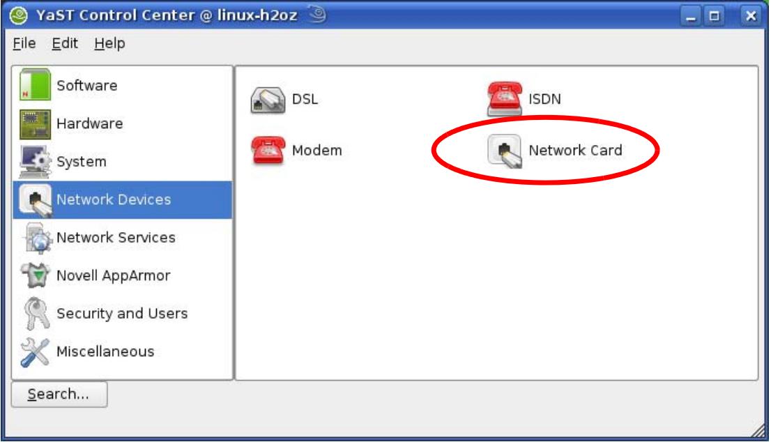
Figure 168 openSUSE 10.3: YaST Control Center
4 When the Network Settings window opens, click the Overview tab, select the appropriate connection Name from the list, and then click the Configure button.
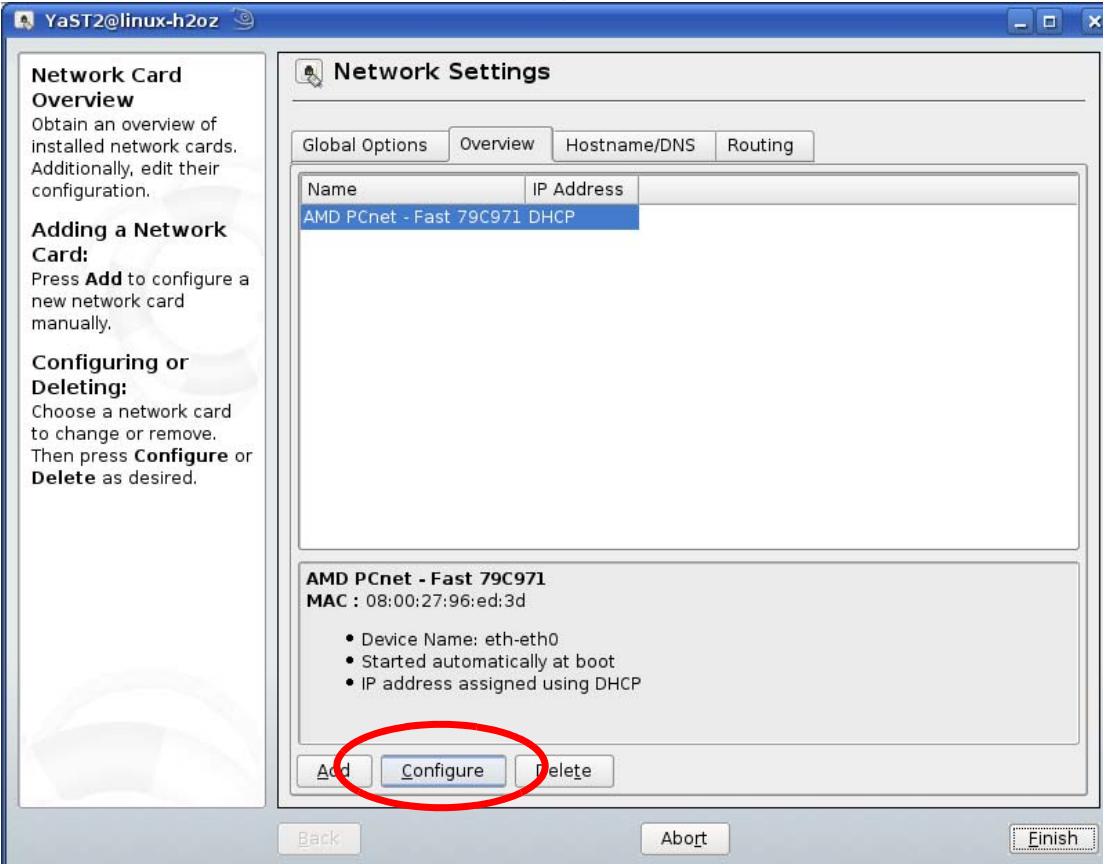
Figure 169 openSUSE 10.3: Network Settings
5 When the Network Card Setup window opens, click the Address tab
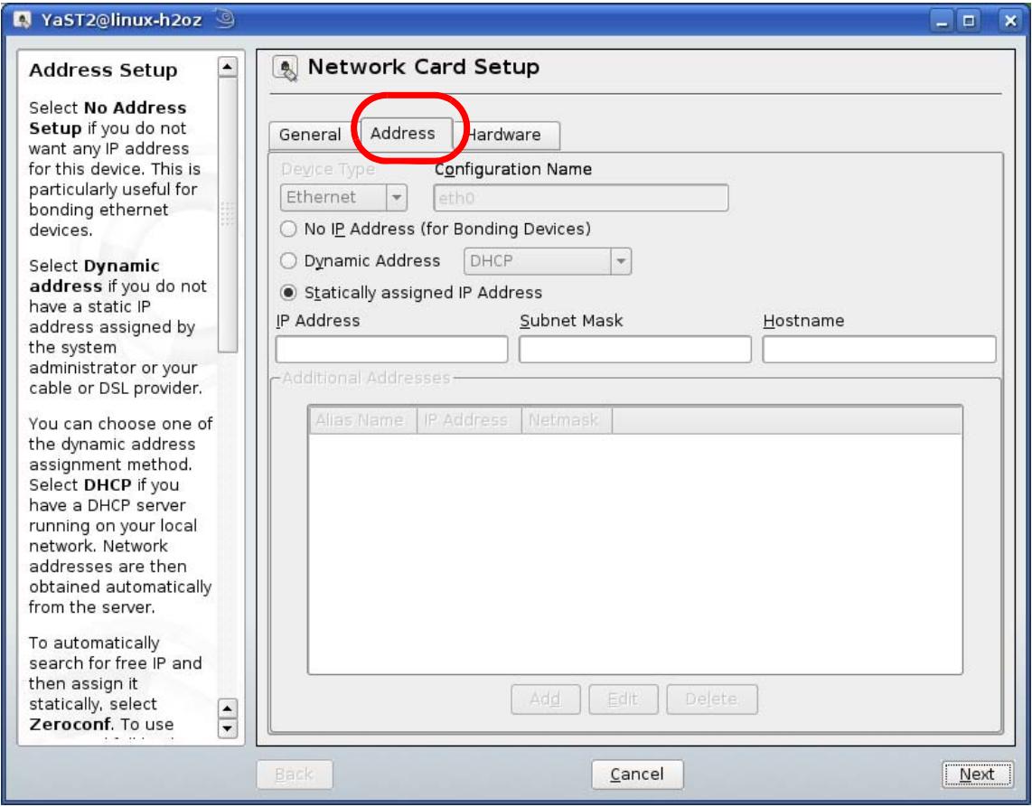
Figure 170 openSUSE 10.3: Network Card Setup
6 Select Dynamic Address (DHCP) if you have a dynamic IP address. Select statically assigned IP Address if you have a static IP address. Fill in the IP address, Subnet mask, and Hostname fields.
7 Click Next to save the changes and close the Network Card Setup window.
8 If you know your DNS server IP address(es), click the Hostname/DNS tab in Network Settings and then enter the DNS server information in the fields provided.
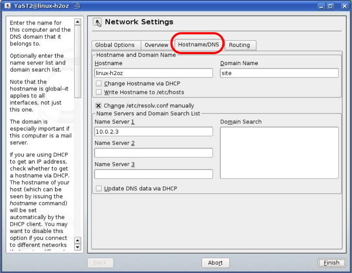
Figure 171 openSUSE 10.3: Network Settings
9 Click Finish to save your settings and close the window.
Verifying Settings
Click the KNetwork Manager icon on the Task bar to check your TCP/IP properties. From the Options sub-menu, select Show Connection Information.
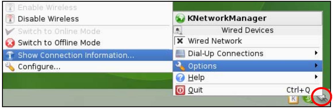
Figure 172 openSUSE 10.3: KNetwork Manager
When the Connection Status - KNetwork Manager window opens, click the Statistics tab to see if your connection is working properly.
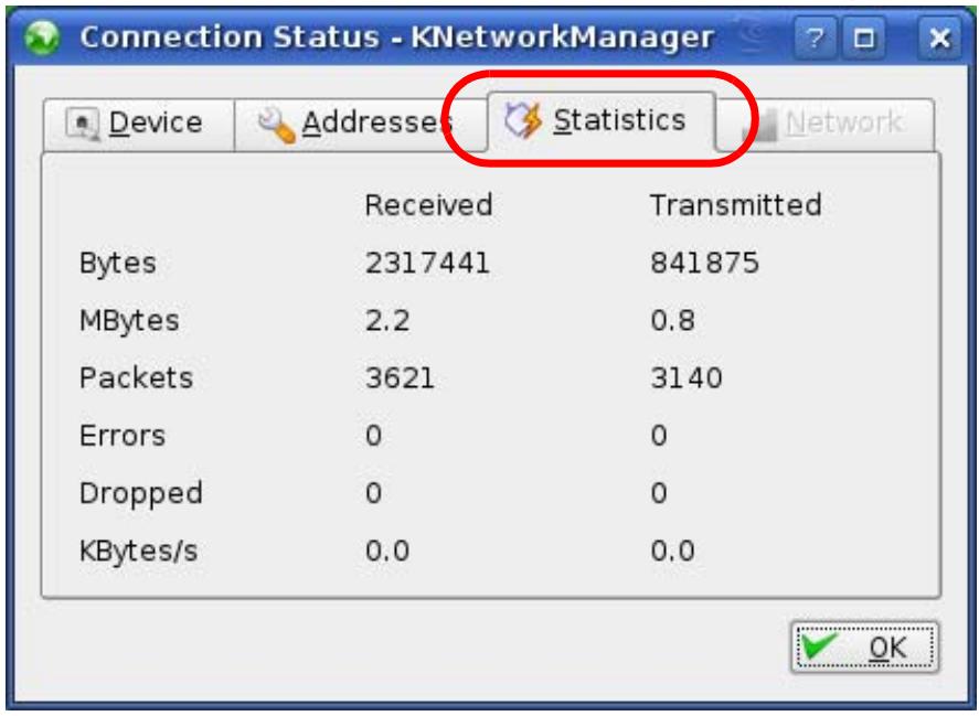
Figure 173 openSUSE: Connection Status - KNetwork Manager
Wireless LANs
Wireless LAN Topologies
This section discusses ad-hoc and infrastructure wireless LAN topologies.
Ad-hoc Wireless LAN Configuration
The simplest WLAN configuration is an independent (Ad-hoc) WLAN that connects a set of computers with wireless adapters (A, B, C). Any time two or more wireless adapters are within range of each other, they can set up an independent network, which is commonly referred to as an ad-hoc network or Independent Basic Service Set (IBSS). The following diagram shows an example of notebook computers using wireless adapters to form an ad-hoc wireless LAN.
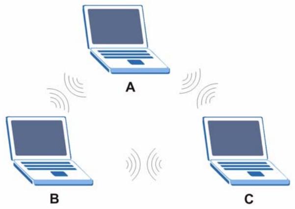
Figure 174 Peer-to-Peer Communication in an Ad-hoc Network
BSS
A Basic Service Set (BSS) exists when all communications between wireless clients or between a wireless client and a wired network client go through one access point (AP).
Intra-BSS traffic is traffic between wireless clients in the BSS. When Intra-BSS is enabled, wireless client A and B can access the wired network and communicate with each other. When Intra-BSS is disabled, wireless client A and B can still access the wired network but cannot communicate with each other.
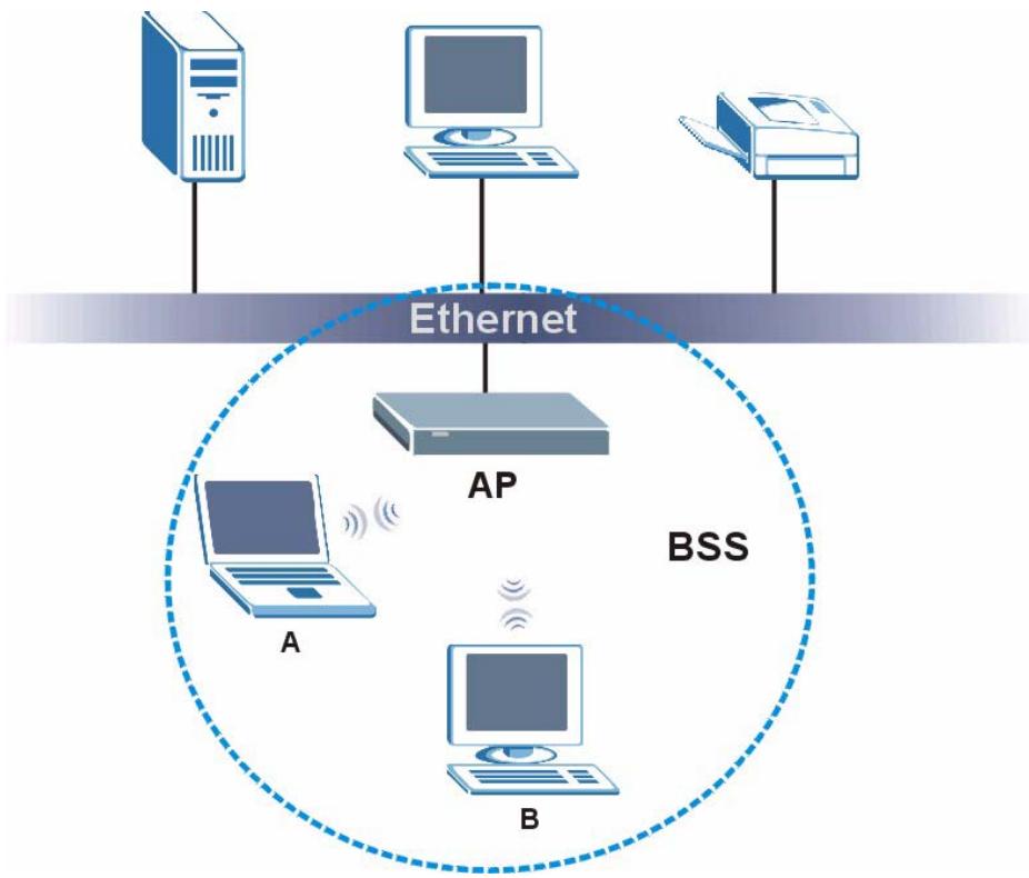
Figure 175 Basic Service Set
ESS
An Extended Service Set (ESS) consists of a series of overlapping BSSs, each containing an access point, with each access point connected together by a wired network. This wired connection between APs is called a Distribution System (DS).
This type of wireless LAN topology is called an Infrastructure WLAN. The Access Points not only provide communication with the wired network but also mediate wireless network traffic in the immediate neighborhood.
An ESSID (ESS IDentification) uniquely identifies each ESS. All access points and their associated wireless clients within the same ESS must have the same ESSID in order to communicate.
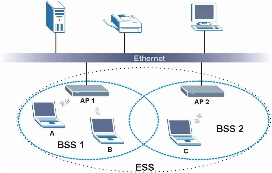
Figure 176 Infrastructure WLAN
Channel
A channel is the radio frequency(ies) used by wireless devices to transmit and receive data. Channels available depend on your geographical area. You may have a choice of channels (for your region) so you should use a channel different from an adjacent AP (access point) to reduce interference. Interference occurs when radio signals from different access points overlap causing interference and degrading performance.
Adjacent channels partially overlap however. To avoid interference due to overlap, your AP should be on a channel at least five channels away from a channel that an adjacent AP is using. For example, if your region has 11 channels and an adjacent AP is using channel 1, then you need to select a channel between 6 or 11.
RTS/CTS
A hidden node occurs when two stations are within range of the same access point, but are not within range of each other. The following figure illustrates a hidden node. Both stations (STA) are within range of the access point (AP) or wireless gateway, but out-of-range of each other, so they cannot "hear" each other, that is they do not know if the channel is currently being used. Therefore, they are considered hidden from each other.
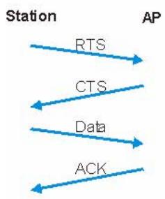
Figure 177 RTS/CTS
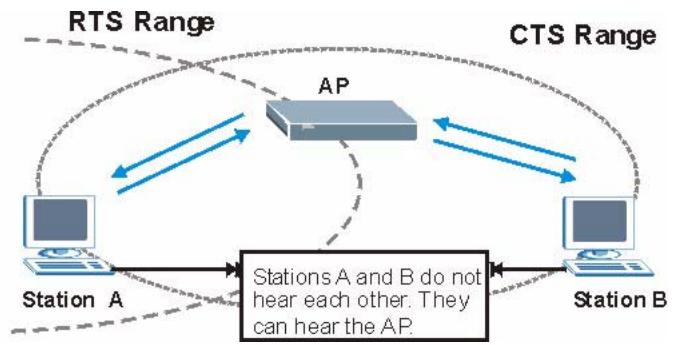
When station A sends data to the AP, it might not know that the station B is already using the channel. If these two stations send data at the same time, collisions may occur when both sets of data arrive at the AP at the same time, resulting in a loss of messages for both stations.
RTS/CTS is designed to prevent collisions due to hidden nodes. An RTS/CTS defines the biggest size data frame you can send before an RTS (Request To Send)/CTS (Clear to Send) handshake is invoked.
When a data frame exceeds the RTS/CTS value you set (between 0 to 2432 bytes), the station that wants to transmit this frame must first send an RTS (Request To Send) message to the AP for permission to send it. The AP then responds with a CTS (Clear to Send) message to all other stations within its range to notify them to defer their transmission. It also reserves and confirms with the requesting station the time frame for the requested transmission.
Stations can send frames smaller than the specified RTS/CTS directly to the AP without the RTS (Request To Send)/CTS (Clear to Send) handshake.
You should only configure RTS/CTS if the possibility of hidden nodes exists on your network and the "cost" of resending large frames is more than the extra network overhead involved in the RTS (Request To Send)/CTS (Clear to Send) handshake.
If the RTS/CTS value is greater than the Fragmentation Threshold value (see next), then the RTS (Request To Send)/CTS (Clear to Send) handshake will never occur as data frames will be fragmented before they reach RTS/CTS size.

Enabling the RTS Threshold causes redundant network overhead that could negatively affect the throughput performance instead of providing a remedy.
Fragmentation Threshold
A Fragmentation Threshold is the maximum data fragment size (between 256 and 2432 bytes) that can be sent in the wireless network before the AP will fragment the packet into smaller data frames.
A large Fragmentation Threshold is recommended for networks not prone to interference while you should set a smaller threshold for busy networks or networks that are prone to interference.
If the Fragmentation Threshold value is smaller than the RTS/CTS value (see previously) you set then the RTS (Request To Send)/CTS (Clear to Send) handshake will never occur as data frames will be fragmented before they reach RTS/CTS size.
Preamble Type
Preamble is used to signal that data is coming to the receiver. Short and long refer to the length of the synchronization field in a packet.
Short preamble increases performance as less time sending preamble means more time for sending data. All IEEE 802.11 compliant wireless adapters support long preamble, but not all support short preamble.
Use long preamble if you are unsure what preamble mode other wireless devices on the network support, and to provide more reliable communications in busy wireless networks.
Use short preamble if you are sure all wireless devices on the network support it, and to provide more efficient communications.
Use the dynamic setting to automatically use short preamble when all wireless devices on the network support it, otherwise the V630 uses long preamble.

The wireless devices MUST use the same preamble mode in order to communicate.
IEEE 802.11g Wireless LAN
IEEE 802.11g is fully compatible with the IEEE 802.11b standard. This means an IEEE 802.11b adapter can interface directly with an IEEE 802.11g access point (and vice versa) at 11 Mbps or lower depending on range. IEEE 802.11g has several intermediate rate steps between the maximum and minimum data rates. The IEEE 802.11g data rate and modulation are as follows:
Table 109 IEEE 802.11g
| DATA RATE (MBPS) | MODULATION |
| 1 | DBPSK (Differential Binary Phase Shift Keyed) |
| 2 | DQPSK (Differential Quadrature Phase Shift Keying) |
| 5.5 / 11 | CCK (Complementary Code Keying) |
| 6/9/12/18/24/36/48/54 | OFDM (Orthogonal Frequency Division Multiplexing) |
Wireless Security Overview
Wireless security is vital to your network to protect wireless communication between wireless clients, access points and the wired network.
Wireless security methods available on the V630 are data encryption, wireless client authentication, restricting access by device MAC address and hiding the V630 identity.
The following figure shows the relative effectiveness of these wireless security methods available on your V630.
Table 110 Wireless Security Levels
| SECURITY LEVEL | SECURITY TYPE |
| Least Secure Most Secure | Unique SSID (Default) |
| Unique SSID with Hide SSID Enabled | |
| MAC Address Filtering | |
| WEP Encryption | |
| IEEE802.1x EAP with RADIUS Server Authentication | |
| Wi-Fi Protected Access (WPA) | |
| WPA2 |

You must enable the same wireless security settings on the V630 and on all wireless clients that you want to associate with it.
IEEE 802.1x
In June 2001, the IEEE 802.1x standard was designed to extend the features of IEEE 802.11 to support extended authentication as well as providing additional accounting and control features. It is supported by Windows XP and a number of network devices. Some advantages of IEEE 802.1x are:
- User based identification that allows for roaming.
- Support for RADIUS (Remote Authentication Dial In User Service, RFC 2138, 2139) for centralized user profile and accounting management on a network RADIUS server.
- Support for EAP (Extensible Authentication Protocol, RFC 2486) that allows additional authentication methods to be deployed with no changes to the access point or the wireless clients.
RADIUS
RADIUS is based on a client-server model that supports authentication, authorization and accounting. The access point is the client and the server is the RADIUS server. The RADIUS server handles the following tasks:
Authentication
Determines the identity of the users.
- Authorization
Determines the network services available to authenticated users once they are connected to the network.
- Accounting
Keeps track of the client's network activity.
RADIUS is a simple package exchange in which your AP acts as a message relay between the wireless client and the network RADIUS server.
Types of RADIUS Messages
The following types of RADIUS messages are exchanged between the access point and the RADIUS server for user authentication:
- Access-Request
Sent by an access point requesting authentication.
- Access-Reject
Sent by a RADIUS server rejecting access.
- Access-Accept
Sent by a RADIUS server allowing access.
- Access-Challenge
Sent by a RADIUS server requesting more information in order to allow access. The access point sends a proper response from the user and then sends another Access-Request message.
The following types of RADIUS messages are exchanged between the access point and the RADIUS server for user accounting:
- Accounting-Request
Sent by the access point requesting accounting.
- Accounting-Response
Sent by the RADIUS server to indicate that it has started or stopped accounting.
In order to ensure network security, the access point and the RADIUS server use a shared secret key, which is a password, they both know. The key is not sent over the network. In addition to the shared key, password information exchanged is also encrypted to protect the network from unauthorized access.
Types of EAP Authentication
This section discusses some popular authentication types: EAP-MD5, EAP-TLS, EAP-TTLS, PEAP and LEAP. Your wireless LAN device may not support all authentication types.
EAP (Extensible Authentication Protocol) is an authentication protocol that runs on top of the IEEE 802.1x transport mechanism in order to support multiple types of user authentication. By using EAP to interact with an EAP-compatible RADIUS server, an access point helps a wireless station and a RADIUS server perform authentication.
The type of authentication you use depends on the RADIUS server and an intermediary AP(s) that supports IEEE 802.1x..
For EAP-TLS authentication type, you must first have a wired connection to the network and obtain the certificate(s) from a certificate authority (CA). A certificate (also called digital IDs) can be used to authenticate users and a CA issues certificates and guarantees the identity of each certificate owner.
EAP-MD5 (Message-Digest Algorithm 5)
MD5 authentication is the simplest one-way authentication method. The authentication server sends a challenge to the wireless client. The wireless client 'proves' that it knows the password by encrypting the password with the challenge and sends back the information. Password is not sent in plain text.
However, MD5 authentication has some weaknesses. Since the authentication server needs to get the plaintext passwords, the passwords must be stored. Thus someone other than the authentication server may access the password file. In addition, it is possible to impersonate an authentication server as MD5 authentication method does not perform mutual authentication. Finally, MD5 authentication method does not support data encryption with dynamic session key. You must configure WEP encryption keys for data encryption.
EAP-TLS (Transport Layer Security)
With EAP-TLS, digital certifications are needed by both the server and the wireless clients for mutual authentication. The server presents a certificate to the client. After validating the identity of the server, the client sends a different certificate to the server. The exchange of certificates is done in the open before a secured tunnel is created. This makes user identity vulnerable to passive attacks. A digital certificate is an electronic ID card that authenticates the sender's identity. However, to implement EAP-TLS, you need a Certificate Authority (CA) to handle certificates, which imposes a management overhead.
EAP-TTLS (Tunnel Transport Layer Service)
EAP-TTLS is an extension of the EAP-TLS authentication that uses certificates for only the server-side authentications to establish a secure connection. Client authentication is then done by sending username and password through the secure connection, thus client identity is protected. For client authentication, EAP-TTLS supports EAP methods and legacy authentication methods such as PAP, CHAP, MS-CHAP and MS-CHAP v2.
PEAP (Protected EAP)
Like EAP-TTLS, server-side certificate authentication is used to establish a secure connection, then use simple username and password methods through the secured connection to authenticate the clients, thus hiding client identity. However, PEAP only supports EAP methods, such as EAP-MD5, EAP-MSCHAPv2 and EAP-GTC (EAP-Generic Token Card), for client authentication. EAP-GTC is implemented only by Cisco.
LEAP
LEAP (Lightweight Extensible Authentication Protocol) is a Cisco implementation of IEEE 802.1x.
Dynamic WEP Key Exchange
The AP maps a unique key that is generated with the RADIUS server. This key expires when the wireless connection times out, disconnects or reauthentication times out. A new WEP key is generated each time reauthentication is performed.
If this feature is enabled, it is not necessary to configure a default encryption key in the wireless security configuration screen. You may still configure and store keys, but they will not be used while dynamic WEP is enabled.

EAP-MD5 cannot be used with Dynamic WEP Key Exchange
For added security, certificate-based authentications (EAP-TLS, EAP-TTLS and PEAP) use dynamic keys for data encryption. They are often deployed in corporate environments, but for public deployment, a simple user name and password pair is more practical. The following table is a comparison of the features of authentication types.
Table 111 Comparison of EAP Authentication Types
| EAP-MD5 | EAP-TLS | EAP-TTLS | PEAP | LEAP | |
| Mutual Authentication | No | Yes | Yes | Yes | Yes |
| Certificate – Client | No | Yes | Optional | Optional | No |
| Certificate – Server | No | Yes | Yes | Yes | No |
| Dynamic Key Exchange | No | Yes | Yes | Yes | Yes |
| Credential Integrity | None | Strong | Strong | Strong | Moderate |
| Deployment Difficulty | Easy | Hard | Moderate | Moderate | Moderate |
| Client Identity Protection | No | No | Yes | Yes | No |
WPA and WPA2
Wi-Fi Protected Access (WPA) is a subset of the IEEE 802.11i standard. WPA2 (IEEE 802.11i) is a wireless security standard that defines stronger encryption, authentication and key management than WPA.
Key differences between WPA or WPA2 and WEP are improved data encryption and user authentication.
If both an AP and the wireless clients support WPA2 and you have an external RADIUS server, use WPA2 for stronger data encryption. If you don't have an external RADIUS server, you should use WPA2-PSK (WPA2-Pre-Shared Key) that only requires a single (identical) password entered into each access point, wireless gateway and wireless client. As long as the passwords match, a wireless client will be granted access to a WLAN.
If the AP or the wireless clients do not support WPA2, just use WPA or WPA-PSK depending on whether you have an external RADIUS server or not.
Select WEP only when the AP and/or wireless clients do not support WPA or WPA2. WEP is less secure than WPA or WPA2.
Encryption
WPA improves data encryption by using Temporal Key Integrity Protocol (TKIP), Message Integrity Check (MIC) and IEEE 802.1x. WPA2 also uses TKIP when required for compatibility reasons, but offers stronger encryption than TKIP with Advanced Encryption Standard (AES) in the Counter mode with Cipher block chaining Message authentication code Protocol (CCMP).
TKIP uses 128-bit keys that are dynamically generated and distributed by the authentication server. AES (Advanced Encryption Standard) is a block cipher that uses a 256-bit mathematical algorithm called Rijndael. They both include a per-packet key mixing function, a Message Integrity Check (MIC) named Michael, an extended initialization vector (IV) with sequencing rules, and a re-keying mechanism.
WPA and WPA2 regularly change and rotate the encryption keys so that the same encryption key is never used twice.
The RADIUS server distributes a Pairwise Master Key (PMK) key to the AP that then sets up a key hierarchy and management system, using the PMK to dynamically generate unique data encryption keys to encrypt every data packet that is wirelessly communicated between the AP and the wireless clients. This all happens in the background automatically.
The Message Integrity Check (MIC) is designed to prevent an attacker from capturing data packets, altering them and resending them. The MIC provides a strong mathematical function in which the receiver and the transmitter each compute and then compare the MIC. If they do not match, it is assumed that the data has been tampered with and the packet is dropped.
By generating unique data encryption keys for every data packet and by creating an integrity checking mechanism (MIC), with TKIP and AES it is more difficult to decrypt data on a Wi-Fi network than WEP and difficult for an intruder to break into the network.
The encryption mechanisms used for WPA(2) and WPA(2)-PSK are the same. The only difference between the two is that WPA(2)-PSK uses a simple common password, instead of user-specific credentials. The common-password approach makes WPA(2)-PSK susceptible to brute-force password-guessing attacks but it's still an improvement over WEP as it employs a consistent, single, alphanumeric password to derive a PMK which is used to generate unique temporal encryption keys. This prevent all wireless devices sharing the same encryption keys. (a weakness of WEP)
User Authentication
WPA and WPA2 apply IEEE 802.1x and Extensible Authentication Protocol (EAP) to authenticate wireless clients using an external RADIUS database. WPA2 reduces the number of key exchange messages from six to four (CCMP 4-way handshake) and shortens the time required to connect to a network. Other WPA2 authentication features that are different from WPA include key caching and pre-authentication. These two features are optional and may not be supported in all wireless devices.
Key caching allows a wireless client to store the PMK it derived through a successful authentication with an AP. The wireless client uses the PMK when it tries to connect to the same AP and does not need to go with the authentication process again.
Pre-authentication enables fast roaming by allowing the wireless client (already connecting to an AP) to perform IEEE 802.1x authentication with another AP before connecting to it.
Wireless Client WPA Suppliers
A wireless client supplicant is the software that runs on an operating system instructing the wireless client how to use WPA. At the time of writing, the most widely available supplicant is the WPA patch for Windows XP, Funk Software's Odyssey client.
The Windows XP patch is a free download that adds WPA capability to Windows XP's built-in "Zero Configuration" wireless client. However, you must run Windows XP to use it.
WPA(2) with RADIUS Application Example
To set up WPA(2), you need the IP address of the RADIUS server, its port number (default is 1812), and the RADIUS shared secret. A WPA(2) application example with an external RADIUS server looks as follows. "A" is the RADIUS server. "DS" is the distribution system.
1 The AP passes the wireless client's authentication request to the RADIUS server.
2 The RADIUS server then checks the user's identification against its database and grants or denies network access accordingly.
3 A 256-bit Pairwise Master Key (PMK) is derived from the authentication process by the RADIUS server and the client.
4 The RADIUS server distributes the PMK to the AP. The AP then sets up a key hierarchy and management system, using the PMK to dynamically generate unique data encryption keys. The keys are used to encrypt every data packet that is wirelessly communicated between the AP and the wireless clients.
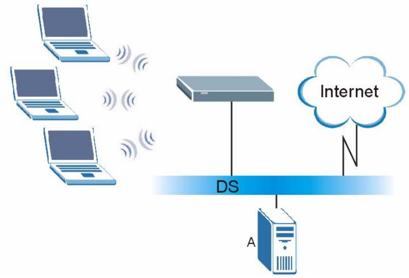
Figure 178 WPA(2) with RADIUS Application Example
WPA(2)-PSK Application Example
A WPA(2)-PSK application looks as follows.
1 First enter identical passwords into the AP and all wireless clients. The Pre-Shared Key (PSK) must consist of between 8 and 63 ASCII characters or 64 hexadecimal characters (including spaces and symbols).
2 The AP checks each wireless client's password and allows it to join the network only if the password matches.
3 The AP and wireless clients generate a common PMK (Pairwise Master Key). The key itself is not sent over the network, but is derived from the PSK and the SSID.
4 The AP and wireless clients use the TKIP or AES encryption process, the PMK and information exchanged in a handshake to create temporal encryption keys. They use these keys to encrypt data exchanged between them.
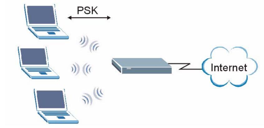
Figure 179 WPA(2)-PSK Authentication
Security Parameters Summary
Refer to this table to see what other security parameters you should configure for each authentication method or key management protocol type. MAC address filters are not dependent on how you configure these security features.
Table 112 Wireless Security Relational Matrix
| AUTHENTICATION METHOD/ KEYMANAGEMENT PROTOCOL | ENCRYPTION METHOD | ENTERMANUAL KEY | IEEE 802.1X |
| Open | None | No | Disable |
| Enable without Dynamic WEP Key | |||
| Open | WEP | No | Enable with Dynamic WEP Key |
| Yes | Enable without Dynamic WEP Key | ||
| Yes | Disable | ||
| Shared | WEP | No | Enable with Dynamic WEP Key |
| Yes | Enable without Dynamic WEP Key | ||
| Yes | Disable | ||
| WPA | TKIP/AES | No | Enable |
| WPA-PSK | TKIP/AES | Yes | Disable |
| WPA2 | TKIP/AES | No | Enable |
| WPA2-PSK | TKIP/AES | Yes | Disable |
Pop-up Windows, JavaScript and Java Permissions
In order to use the web configurator you need to allow:
- Web browser pop-up windows from your device.
- JavaScripts (enabled by default).
- Java permissions (enabled by default).

Internet Explorer 6 screens are used here. Screens for other Internet Explorer versions may vary.
Internet Explorer Pop-up Blockers
You may have to disable pop-up blocking to log into your device.
Either disable pop-up blocking (enabled by default in Windows XP SP (Service Pack) 2) or allow pop-up blocking and create an exception for your device's IP address.
Disable Pop-up Blockers
1 In Internet Explorer, select Tools, Pop-up Blocker and then select Turn Off Pop-up Blocker.
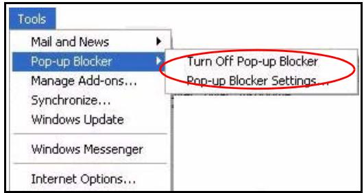
Figure 180 Pop-up Blocker
You can also check if pop-up blocking is disabled in the Pop-up Blocker section in the Privacy tab.
1 In Internet Explorer, select Tools, Internet Options, Privacy.
2 Clear the Block pop-ups check box in the Pop-up Blocker section of the screen. This disables any web pop-up blockers you may have enabled.
Figure 181 Internet Options: Privacy
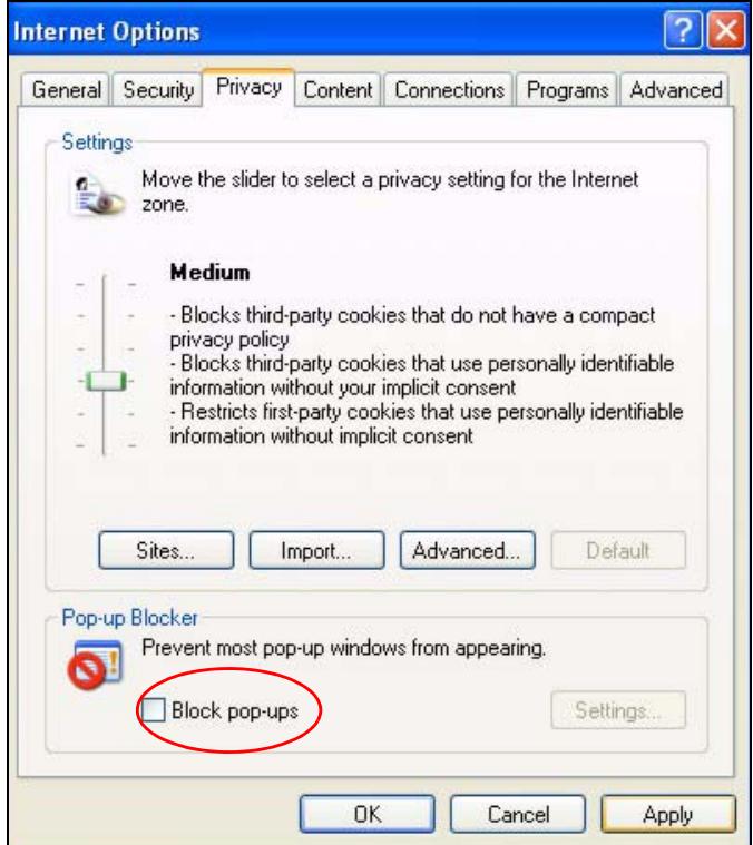
3 Click Apply to save this setting.
Enable Pop-up Blockers with Exceptions
Alternatively, if you only want to allow pop-up windows from your device, see the following steps.
1 In Internet Explorer, select Tools, Internet Options and then the Privacy tab.
2 Select Settings...to open the Pop-up Blocker Settings screen.
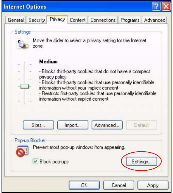
Figure 182 Internet Options: Privacy
3 Type the IP address of your device (the web page that you do not want to have blocked) with the prefix "http://". For example, http://192.168.167.1.
4 Click Add to move the IP address to the list of Allowed sites.
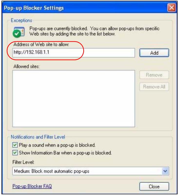
Figure 183 Pop-up Blocker Settings
5 Click Close to return to the Privacy screen.
6 Click Apply to save this setting.
JavaScript
If pages of the web configurator do not display properly in Internet Explorer, check that JavaScripts are allowed.
1 In Internet Explorer, click Tools, Internet Options and then the Security tab.
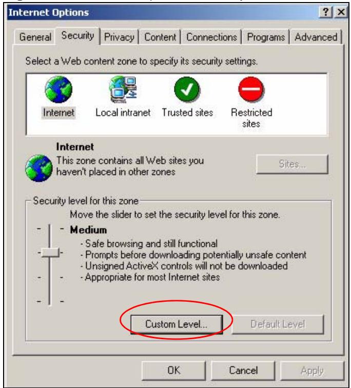
Figure 184 Internet Options: Security
2 Click the Custom Level... button.
3 Scroll down to Scripting.
4 Under Active scripting make sure that Enable is selected (the default).
5 Under Scripting of Java applets make sure that Enable is selected (the default).
6 Click OK to close the window.
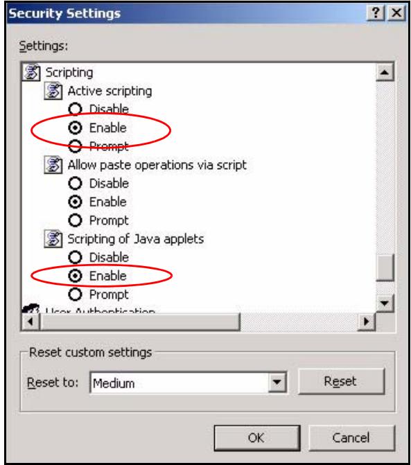
Figure 185 Security Settings - Java Scripting
Java Permissions
1 From Internet Explorer, click Tools, Internet Options and then the Security tab.
2 Click the Custom Level... button.
3 Scroll down to Microsoft VM.
4 Under Java permissions make sure that a safety level is selected.
5 Click OK to close the window.
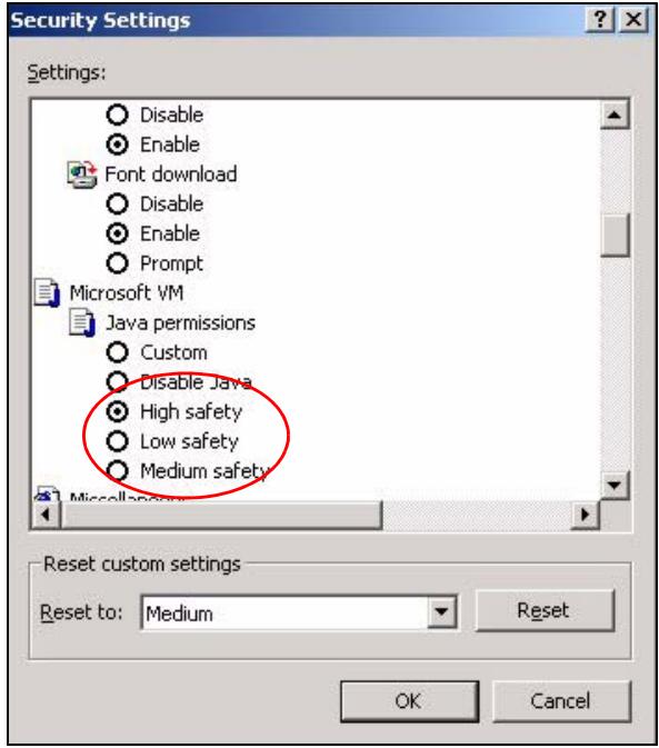
Figure 186 Security Settings - Java
JAVA (Sun)
1 From Internet Explorer, click Tools, Internet Options and then the Advanced tab.
2 Make sure that Use Java 2 for
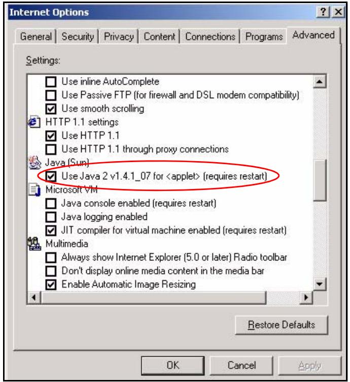
Figure 187 Java (Sun)
Mozilla Firefox
Mozilla Firefox 2.0 screens are used here. Screens for other versions may vary.
You can enable Java, Javascripts and pop-ups in one screen. Click Tools, then click Options in the screen that appears.
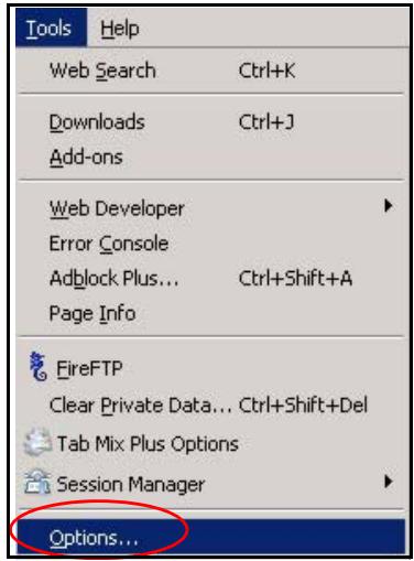
Figure 188 Mozilla Firefox: Tools > Options
Click Content.to show the screen below. Select the check boxes as shown in the following screen.
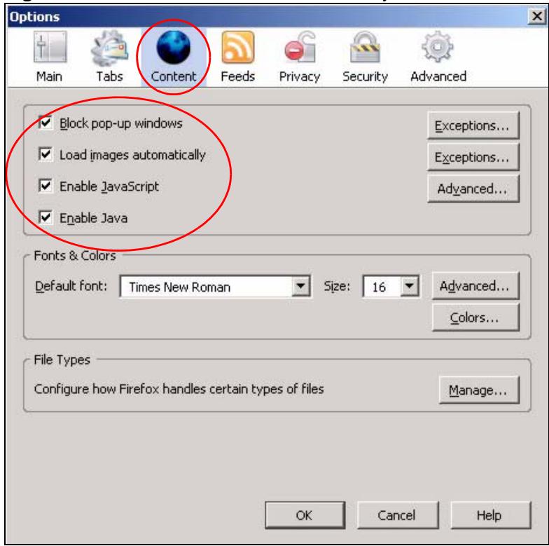
Figure 189 Mozilla Firefox Content Security
IP Addresses and Subnetting
This appendix introduces IP addresses and subnet masks.
IP addresses identify individual devices on a network. Every networking device (including computers, servers, routers, printers, etc.) needs an IP address to communicate across the network. These networking devices are also known as hosts.
Subnet masks determine the maximum number of possible hosts on a network. You can also use subnet masks to divide one network into multiple sub-networks.
Introduction to IP Addresses
One part of the IP address is the network number, and the other part is the host ID. In the same way that houses on a street share a common street name, the hosts on a network share a common network number. Similarly, as each house has its own house number, each host on the network has its own unique identifying number - the host ID. Routers use the network number to send packets to the correct network, while the host ID determines to which host on the network the packets are delivered.
Structure
An IP address is made up of four parts, written in dotted decimal notation (for example, 192.168.1.1). Each of these four parts is known as an octet. An octet is an eight-digit binary number (for example 11000000, which is 192 in decimal notation).
Therefore, each octet has a possible range of 00000000 to 11111111 in binary, or 0 to 255 in decimal.
The following figure shows an example IP address in which the first three octets (192.168.1) are the network number, and the fourth octet (16) is the host ID.
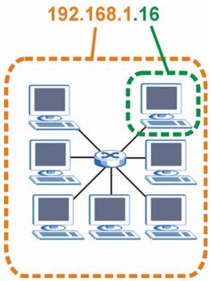
Figure 190 Network Number and Host ID
How much of the IP address is the network number and how much is the host ID varies according to the subnet mask.
Subnet Masks
A subnet mask is used to determine which bits are part of the network number, and which bits are part of the host ID (using a logical AND operation). The term "subset" is short for "subnetwork".
A subnet mask has 32 bits. If a bit in the subnet mask is a "1" then the corresponding bit in the IP address is part of the network number. If a bit in the subnet mask is "0" then the corresponding bit in the IP address is part of the host ID.
The following example shows a subnet mask identifying the network number (in bold text) and host ID of an IP address (192.168.1.2 in decimal).
Table 113 IP Address Network Number and Host ID Example
| 1ST OCTET: (192) | 2ND OCTET: (168) | 3RD OCTET: (1) | 4TH OCTET (2) | |
| IP Address (Binary) | 11000000 | 10101000 | 00000001 | 00000010 |
| Subnet Mask (Binary) | 11111111 | 11111111 | 11111111 | 00000000 |
| Network Number | 11000000 | 10101000 | 00000001 | |
| Host ID | 00000010 |
By convention, subnet masks always consist of a continuous sequence of ones beginning from the leftmost bit of the mask, followed by a continuous sequence of zeros, for a total number of 32 bits.
Subnet masks can be referred to by the size of the network number part (the bits with a "1" value). For example, an "8-bit mask" means that the first 8 bits of the mask are ones and the remaining 24 bits are zeroes.
Subnet masks are expressed in dotted decimal notation just like IP addresses. The following examples show the binary and decimal notation for 8-bit, 16-bit, 24-bit and 29-bit subnet masks.
Table 114 Subnet Masks
| BINARY | DECIMAL | ||||
| 1ST OCTET | 2ND OCTET | 3RD OCTET | 4TH OCTET | ||
| 8-bit mask | 11111111 | 00000000 | 00000000 | 00000000 | 255.0.0.0 |
| 16-bit mask | 11111111 | 11111111 | 00000000 | 00000000 | 255.255.0.0 |
| 24-bit mask | 11111111 | 11111111 | 11111111 | 00000000 | 255.255.255.0 |
| 29-bit mask | 11111111 | 11111111 | 11111111 | 11111000 | 255.255.255.248 |
Network Size
The size of the network number determines the maximum number of possible hosts you can have on your network. The larger the number of network number bits, the smaller the number of remaining host ID bits.
An IP address with host IDs of all zeros is the IP address of the network (192.168.1.0 with a 24-bit subnet mask, for example). An IP address with host IDs of all ones is the broadcast address for that network (192.168.1.255 with a 24-bit subnet mask, for example).
As these two IP addresses cannot be used for individual hosts, calculate the maximum number of possible hosts in a network as follows:
Table 115 Maximum Host Numbers
| SUBNET MASK | HOST ID SIZE | MAXIMUM NUMBER OF HOSTS | ||
| 8 bits | 255.0.0.0 | 24 bits | \( 2^{24} - 2 \) | 16777214 |
| 16 bits | 255.255.0.0 | 16 bits | \( 2^{16} - 2 \) | 65534 |
| 24 bits | 255.255.255.0 | 8 bits | \( 2^8 - 2 \) | 254 |
| 29 bits | 255.255.255.248 | 3 bits | \( 2^3 - 2 \) | 6 |
Notation
Since the mask is always a continuous number of ones beginning from the left, followed by a continuous number of zeros for the remainder of the 32 bit mask, you can simply specify the number of ones instead of writing the value of each octet. This is usually specified by writing a “/” followed by the number of bits in the mask after the address.
For example, 192.1.1.0 /25 is equivalent to saying 192.1.1.0 with subnet mask 255.255.255.128.
The following table shows some possible subnet masks using both notations.
Table 116 Alternative Subnet Mask Notation
| SUBNET MASK | ALTERNATIVE NOTATION | LAST OCTET (BINARY) | LAST OCTET (DECIMAL) |
| 255.255.255.0 | /24 | 0000 0000 | 0 |
| 255.255.255.128 | /25 | 1000 0000 | 128 |
| 255.255.255.192 | /26 | 1100 0000 | 192 |
| 255.255.255.224 | /27 | 1110 0000 | 224 |
| 255.255.255.240 | /28 | 1111 0000 | 240 |
| 255.255.255.248 | /29 | 1111 1000 | 248 |
| 255.255.255.252 | /30 | 1111 1100 | 252 |
Subnetting
You can use subnetting to divide one network into multiple sub-networks. In the following example a network administrator creates two sub-networks to isolate a group of servers from the rest of the company network for security reasons.
In this example, the company network address is 192.168.1.0. The first three octets of the address (192.168.1) are the network number, and the remaining octet is the host ID, allowing a maximum of 2^8 - 2 or 254 possible hosts.
The following figure shows the company network before subnetting.
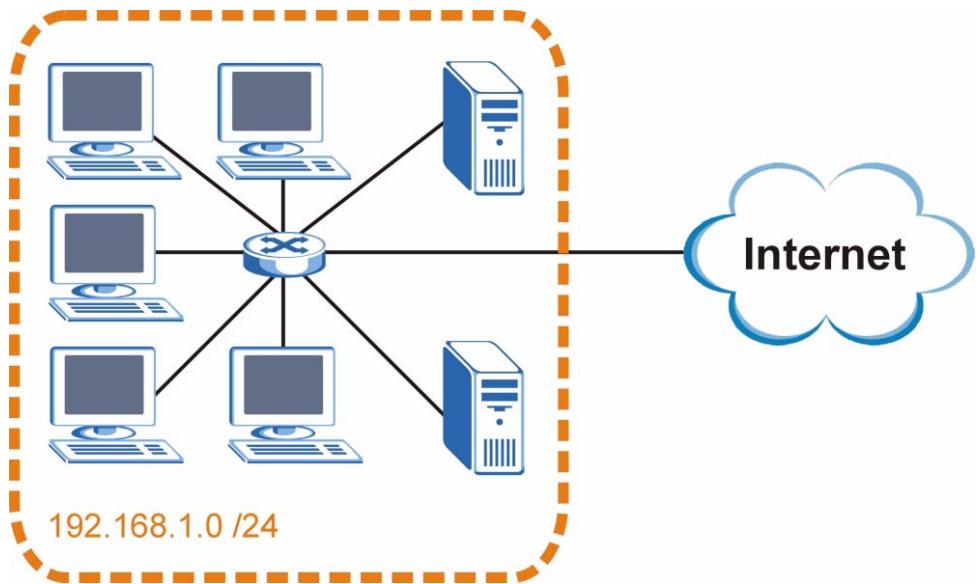
Figure 191 Subnetting Example: Before Subnetting
You can "borrow" one of the host ID bits to divide the network 192.168.1.0 into two separate sub-networks. The subnet mask is now 25 bits (255.255.255.128 or /25).
The "borrowed" host ID bit can have a value of either 0 or 1, allowing two subnets; 192.168.1.0 /25 and 192.168.1.128 /25.
The following figure shows the company network after subnetting. There are now two subnetworks, A and B.
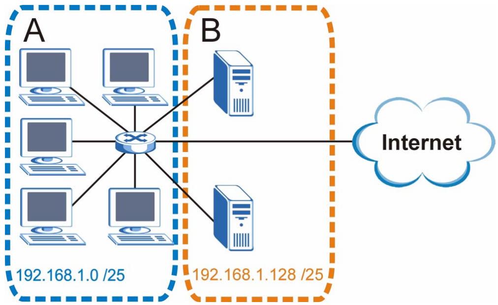
Figure 192 Subnetting Example: After Subnetting
In a 25-bit subnet the host ID has 7 bits, so each sub-network has a maximum of 2^7 - 2 or 126 possible hosts (a host ID of all zeroes is the subnet's address itself, all ones is the subnet's broadcast address).
192.168.1.0 with mask 255.255.255.128 is subnet A itself, and 192.168.1.127 with mask 255.255.255.128 is its broadcast address. Therefore, the lowest IP address that can be assigned to an actual host for subnet A is 192.168.1.1 and the highest is 192.168.1.126.
Similarly, the host ID range for subnet B is 192.168.1.129 to 192.168.1.254.
Example: Four Subnets
The previous example illustrated using a 25-bit subnet mask to divide a 24-bit address into two subnets. Similarly, to divide a 24-bit address into four subnets, you need to "borrow" two host ID bits to give four possible combinations (00, 01, 10 and 11). The subnet mask is 26 bits (11111111.11111111.11111111.1000000) or 255.255.255.192.
Each subnet contains 6 host ID bits, giving 2^6 - 2 or 62 hosts for each subnet (a host ID of all zeroes is the subnet itself, all ones is the subnet's broadcast address).
Table 117 Subnet 1
| IP/SUBNET MASK | NETWORK NUMBER | LAST OCTET BIT VALUE |
| IP Address (Decimal) | 192.168.1. | 0 |
| IP Address (Binary) | 11000000.10101000.00000001. | 00000000 |
| Subnet Mask (Binary) | 11111111.11111111.11111111. | 11000000 |
| Subnet Address: 192.168.1.0 | Lowest Host ID: 192.168.1.1 | |
| Broadcast Address: 192.168.1.63 | Highest Host ID: 192.168.1.62 | |
Table 118 Subnet 2
| IP/SUBNET MASK | NETWORK NUMBER | LAST OCTET BIT VALUE |
| IP Address | 192.168.1. | 64 |
| IP Address (Binary) | 11000000.10101000.00000001. | 01000000 |
| Subnet Mask (Binary) | 11111111.11111111.11111111. | 11000000 |
| Subnet Address: 192.168.1.64 | Lowest Host ID: 192.168.1.65 | |
| Broadcast Address: 192.168.1.127 | Highest Host ID: 192.168.1.126 | |
Table 119 Subnet 3
| IP/SUBNET MASK | NETWORK NUMBER | LAST OCTET BIT VALUE |
| IP Address | 192.168.1. | 128 |
| IP Address (Binary) | 11000000.10101000.00000001. | 10000000 |
| Subnet Mask (Binary) | 11111111.11111111.11111111. | 11000000 |
| Subnet Address: 192.168.1.128 | Lowest Host ID: 192.168.1.129 | |
| Broadcast Address: 192.168.1.191 | Highest Host ID: 192.168.1.190 | |
Table 120 Subnet 4
| IP/SUBNET MASK | NETWORK NUMBER | LAST OCTET BIT VALUE |
| IP Address | 192.168.1. | 192 |
| IP Address (Binary) | 11000000.10101000.00000001. | 11000000 |
| Subnet Mask (Binary) | 11111111.11111111.11111111. | 11000000 |
| Subnet Address: 192.168.1.192 | Lowest Host ID: 192.168.1.193 | |
| Broadcast Address: 192.168.1.255 | Highest Host ID: 192.168.1.254 | |
Example: Eight Subnets
Similarly, use a 27-bit mask to create eight subnets (000, 001, 010, 011, 100, 101, 110 and 111).
The following table shows IP address last octet values for each subnet.
Table 121 Eight Subnets
| SUBNET | SUBNET ADDRESS | FIRST ADDRESS | LAST ADDRESS | BROADCAST ADDRESS |
| 1 | 0 | 1 | 30 | 31 |
| 2 | 32 | 33 | 62 | 63 |
| 3 | 64 | 65 | 94 | 95 |
| 4 | 96 | 97 | 126 | 127 |
| 5 | 128 | 129 | 158 | 159 |
| 6 | 160 | 161 | 190 | 191 |
| 7 | 192 | 193 | 222 | 223 |
| 8 | 224 | 225 | 254 | 255 |
Subnet Planning
The following table is a summary for subnet planning on a network with a 24-bit network number.
Table 122 24-bit Network Number Subnet Planning
| NO. “BORROWED” HOST BITS | SUBNET MASK | NO. SUBNETS | NO. HOSTS PER SUBNET |
| 1 | 255.255.255.128 (/25) | 2 | 126 |
| 2 | 255.255.255.192 (/26) | 4 | 62 |
| 3 | 255.255.255.224 (/27) | 8 | 30 |
| 4 | 255.255.255.240 (/28) | 16 | 14 |
| 5 | 255.255.255.248 (/29) | 32 | 6 |
| 6 | 255.255.255.252 (/30) | 64 | 2 |
| 7 | 255.255.255.254 (/31) | 128 | 1 |
The following table is a summary for subnet planning on a network with a 16-bit network number.
Table 123 16-bit Network Number Subnet Planning
| NO. “BORROWED” HOST BITS | SUBNET MASK | NO. SUBNETS | NO. HOSTS PER SUBNET |
| 1 | 255.255.128.0 (/17) | 2 | 32766 |
| 2 | 255.255.192.0 (/18) | 4 | 16382 |
| 3 | 255.255.224.0 (/19) | 8 | 8190 |
| 4 | 255.255.240.0 (/20) | 16 | 4094 |
| 5 | 255.255.248.0 (/21) | 32 | 2046 |
| 6 | 255.255.252.0 (/22) | 64 | 1022 |
| 7 | 255.255.254.0 (/23) | 128 | 510 |
| 8 | 255.255.255.0 (/24) | 256 | 254 |
| 9 | 255.255.255.128 (/25) | 512 | 126 |
| 10 | 255.255.255.192 (/26) | 1024 | 62 |
| 11 | 255.255.255.224 (/27) | 2048 | 30 |
| 12 | 255.255.255.240 (/28) | 4096 | 14 |
| 13 | 255.255.255.248 (/29) | 8192 | 6 |
| 14 | 255.255.255.252 (/30) | 16384 | 2 |
| 15 | 255.255.255.254 (/31) | 32768 | 1 |
Configuring IP Addresses
Where you obtain your network number depends on your particular situation. If the ISP or your network administrator assigns you a block of registered IP addresses, follow their instructions in selecting the IP addresses and the subnet mask.
If the ISP did not explicitly give you an IP network number, then most likely you have a single user account and the ISP will assign you a dynamic IP address when the connection is established. If this is the case, it is recommended that you select a network number from 192.168.0.0 to 192.168.255.0. The Internet Assigned Number Authority (IANA) reserved this block of addresses specifically for private use; please do not use any other number unless you are told otherwise. You must also enable Network Address Translation (NAT) on the V630.
Once you have decided on the network number, pick an IP address for your V630 that is easy to remember (for instance, 192.168.1.1) but make sure that no other device on your network is using that IP address.
The subnet mask specifies the network number portion of an IP address. Your V630 will compute the subnet mask automatically based on the IP address that you entered. You don't need to change the subnet mask computed by the V630 unless you are instructed to do otherwise.
Private IP Addresses
Every machine on the Internet must have a unique address. If your networks are isolated from the Internet (running only between two branch offices, for example) you can assign any IP addresses to the hosts without problems. However, the Internet Assigned Numbers Authority (IANA) has reserved the following three blocks of IP addresses specifically for private networks:
10.0.0.0 10.255.255.255
172.16.0.0 — 172.31.255.255
192.168.0.0 — 192.168.255.255
You can obtain your IP address from the IANA, from an ISP, or it can be assigned from a private network. If you belong to a small organization and your Internet access is through an ISP, the ISP can provide you with the Internet addresses for your local networks. On the other hand, if you are part of a much larger organization, you should consult your network administrator for the appropriate IP addresses.
Regardless of your particular situation, do not create an arbitrary IP address; always follow the guidelines above. For more information on address assignment, please refer to RFC 1597, Address Allocation for Private Internets and RFC 1466, Guidelines for Management of IP Address Space.
IP Address Conflicts
Each device on a network must have a unique IP address. Devices with duplicate IP addresses on the same network will not be able to access the Internet or other resources. The devices may also be unreachable through the network.
Conflicting Computer IP Addresses Example
More than one device can not use the same IP address. In the following example computer A has a static (or fixed) IP address that is the same as the IP address that a DHCP server assigns to computer B which is a DHCP client. Neither can access the Internet. This problem can be solved by assigning a different static IP address to computer A or setting computer A to obtain an IP address automatically.
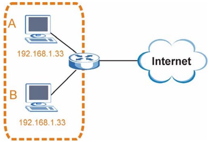
Figure 193 Conflicting Computer IP Addresses Example
Conflicting Router IP Addresses Example
Since a router connects different networks, it must have interfaces using different network numbers. For example, if a router is set between a LAN and the Internet (WAN), the router's LAN and WAN addresses must be on different subnets. In the following example, the LAN and WAN are on the same subnet. The LAN computers cannot access the Internet because the router cannot route between networks.
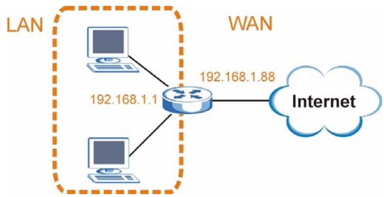
Figure 194 Conflicting Computer IP Addresses Example
Conflicting Computer and Router IP Addresses Example
More than one device can not use the same IP address. In the following example, the computer and the router's LAN port both use 192.168.1.1 as the IP address. The computer cannot access the Internet. This problem can be solved by assigning a different IP address to the computer or the router's LAN port.
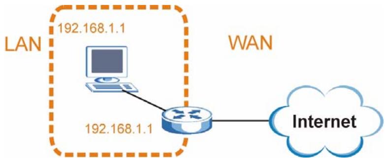
Figure 195 Conflicting Computer and Router IP Addresses Example
Legal Information
Copyright
Copyright © 2008 by ZyXEL Communications Corporation.
The contents of this publication may not be reproduced in any part or as a whole, transcribed, stored in a retrieval system, translated into any language, or transmitted in any form or by any means, electronic, mechanical, magnetic, optical, chemical, photocopying, manual, or otherwise, without the prior written permission of ZyXEL Communications Corporation.
Published by ZyXEL Communications Corporation. All rights reserved.
Disclaimers
ZyXEL does not assume any liability arising out of the application or use of any products, or software described herein. Neither does it convey any license under its patent rights nor the patent rights of others. ZyXEL further reserves the right to make changes in any products described herein without notice. This publication is subject to change without notice.
Your use of the V630 is subject to the terms and conditions of any related service providers.
Trademarks
ZyNOS (ZyXEL Network Operating System) is a registered trademark of ZyXEL Communications, Inc. Other trademarks mentioned in this publication are used for identification purposes only and may be properties of their respective owners.
Certifications
Federal Communications Commission (FCC) Interference Statement
The device complies with Part 15 of FCC rules. Operation is subject to the following two conditions:
- This device may not cause harmful interference.
- This device must accept any interference received, including interference that may cause undesired operations.
This device has been tested and found to comply with the limits for a Class B digital device pursuant to Part 15 of the FCC Rules. These limits are designed to provide reasonable protection against harmful interference in a residential installation. This device generates, uses, and can radiate radio frequency energy, and if not installed and used in accordance with the instructions, may cause harmful interference to radio communications. However, there is no guarantee that interference will not occur in a particular installation.
If this device does cause harmful interference to radio/television reception, which can be determined by turning the device off and on, the user is encouraged to try to correct the interference by one or more of the following measures:
1 Reorient or relocate the receiving antenna.
2 Increase the separation between the equipment and the receiver.
3 Connect the equipment into an outlet on a circuit different from that to which the receiver is connected.
4 Consult the dealer or an experienced radio/TV technician for help.

FCC Radiation Exposure Statement
- This device has been tested to the FCC exposure requirements (Specific Absorption Rate).
- This device complies with the requirements of Health Canada Safety Code 6 for Canada.
- Testing was performed on laptop computers with antennas at 0mm spacing. The maximum SAR value is: 0.128W / kg . The device must not be collocated with any other antennas or transmitters.
- The device complies with FCC RF radiation exposure limits set forth for an uncontrolled environment, under 47 CFR 2.1093 paragraph (d)(2). End users must follow the specific operating instructions for satisfying RF exposure compliance. To maintain compliance with FCC RF exposure compliance requirements, please follow operation instruction as documented in this manual.
- This transmitter must not be co-located or operating in conjunction with any other antenna or transmitter.
- IEEE 802.11b or 802.11g operation of this product in the U.S.A. is firmware-limited to channels 1 through 11.
注意!
依據 低功率電波輻射性電機管理辦法
Changes or modifications not expressly approved by the party responsible for compliance could void the user's authority to operate the equipment.
This device has been designed for the WLAN 2.4 GHz network throughout the EC region and Switzerland, with restrictions in France.
This Class B digital apparatus complies with Canadian ICES-003.
Viewing Certifications
1 Go to http://www.zyxel.com.
2 Select your product on the ZyXEL home page to go to that product's page.
3 Select the certification you wish to view from this page.
ZyXEL Limited Warranty
ZyXEL warrants to the original end user (purchaser) that the V630 (not including the battery) is free from any defects in materials or workmanship for a period of up to two years from the date of purchase. ZyXEL warrants to the original end user (purchaser) that the V630's battery is free from any defects in materials or workmanship for a period of up to three months from the date of purchase. During the warranty period, and upon proof of purchase, should the product have indications of failure due to faulty workmanship and/or materials, ZyXEL will, at its discretion, repair or replace the defective products or components without charge for either parts or labor, and to whatever extent it shall deem necessary to restore the product or components to proper operating condition. Any replacement will consist of a new or remanufactured functionally equivalent product of equal or higher value, and will be solely at the discretion of ZyXEL. This warranty shall not apply if the product has been modified, misused, tampered with, damaged by an act of God, or subjected to abnormal working conditions.
Note
Repair or replacement, as provided under this warranty, is the exclusive remedy of the purchaser. This warranty is in lieu of all other warranties, express or implied, including any implied warranty of merchantability or fitness for a particular use or purpose. ZyXEL shall in no event be held liable for indirect or consequential damages of any kind to the purchaser.
To obtain the services of this warranty, contact your vendor. You may also refer to the warranty policy for the region in which you bought the device at http://www.zyxel.com/web/support_warranty_info.php.
Registration
Register your product online to receive e-mail notices of firmware upgrades and information at www.zyxel.com.
Customer Support
In the event of problems that cannot be solved by using this manual, you should contact your vendor. If you cannot contact your vendor, then contact a ZyXEL office for the region in which you bought the device. Regional offices are listed below (see also http:// www.zyxel.com/web/contact_us.php). Please have the following information ready when you contact an office.
Required Information
Product model and serial number.
Warranty Information.
- Date that you received your device.
- Brief description of the problem and the steps you took to solve it.
“+” is the (prefix) number you dial to make an international telephone call.
Corporate Headquarters (Worldwide)
- Support E-mail: support@zyxel.com.tw
Sales E-mail: sales@zyxel.com.tw
Telephone: +886-3-578-3942
Fax: +886-3-578-2439
Web: www.zyxel.com - Regular Mail: ZyXEL Communications Corp., 6 Innovation Road II, Science Park, Hsinchu 300, Taiwan
China - ZyXEL Communications (Beijing) Corp.
- Support E-mail: cso.zycn@zyxel.cn
Sales E-mail: sales@zyxel.cn
Telephone: +86-010-82800646
Fax: +86-010-82800587 - Address: 902, Unit B, Horizon Building, No.6, Zhichun Str, Haidian District, Beijing
Web: http://www.zyxel.cn
China - ZyXEL Communications (Shanghai) Corp.
-
Support E-mail: cso.zycn@zyxel.cn
Sales E-mail: sales@zyxel.cn
Telephone: +86-021-61199055
Fax: +86-021-52069033 -
Address: 1005F, ShengGao International Tower, No.137 XianXia Rd., Shanghai
Web: http://www.zyxel.cn
Costa Rica
- Support E-mail: soporte@zyxel.co.cr
- Sales E-mail: sales@zyxel.co.cr
Telephone: +506-2017878
Fax: +506-2015098
Web: www.zyxel.co.cr - Regular Mail: ZyXEL Costa Rica, Plaza Roble Escazú, Etapa El Patio, Tercer Piso, San José, Costa Rica
Czech Republic
E-mail: info@cz.zyxel.com
Telephone: +420-241-091-350
Fax: +420-241-091-359
Web: www.zyxel.cz
- Regular Mail: ZyXEL Communications, Czech s.r.o., Modranská 621, 143 01 Praha 4 - Modrany, Ceská Republika
Denmark
- Support E-mail: support@zyxel.dk
Sales E-mail: sales@zyxel.dk
Telephone: +45-39-55-07-00
Fax: +45-39-55-07-07
Web: www.zyxel.dk - Regular Mail: ZyXEL Communications A/S, Columbusvej, 2860 Soeborg, Denmark
Finland
- Support E-mail: support@zyxel.fi
Sales E-mail: sales@zyxel.fi
Telephone: +358-9-4780-8411
Fax: +358-9-4780-8448
Web: www.zyxel.fi - Regular Mail: ZyXEL Communications Oy, Malminkaari 10, 00700 Helsinki, Finland
France
E-mail: info@zyxel.fr
Telephone: +33-4-72-52-97-97
Fax: +33-4-72-52-19-20
Web: www.zyxel.fr
- Regular Mail: ZyXEL France, 1 rue des Vergers, Bat. 1 / C, 69760 Limonest, France
Germany
- Support E-mail: support@zyxel.de
Sales E-mail: sales@zyxel.de
Telephone: +49-2405-6909-69
Fax: +49-2405-6909-99
Web: www.zyxel.de - Regular Mail: ZyXEL Deutschland GmbH., Adenauerstr. 20/A2 D-52146, Wuerselen, Germany
Hungary
- Support E-mail: support@zyxel.hu
Sales E-mail: info@zyxel.hu
Telephone: +36-1-3361649
Fax: +36-1-3259100
Web: www.zyxel.hu
Regular Mail: ZyXEL Hungary, 48, Zoldlomb Str., H-1025, Budapest, Hungary
India
- Support E-mail: support@zyxel.in
Sales E-mail: sales@zyxel.in - Telephone: +91-11-30888144 to +91-11-30888153
Fax: +91-11-30888149, +91-11-26810715
Web: http://www.zyxel.in - Regular Mail: India - ZyXEL Technology India Pvt Ltd., II-Floor, F2/9 Okhra Phase -1, New Delhi 110020, India
Japan
- Support E-mail: support@zyxel.co.jp
Sales E-mail: zyp@zyxel.co.jp
Telephone: +81-3-6847-3700
Fax: +81-3-6847-3705
Web: www.zyxel.co.jp - Regular Mail: ZyXEL Japan, 3F, Office T&U, 1-10-10 Higashi-Gotanda, Shinagawa-ku, Tokyo 141-0022, Japan
Kazakhstan
- Support: http://zyxel.kz/support
Sales E-mail: sales@zyxel.kz
Telephone: +7-3272-590-698
Fax: +7-3272-590-689
Web: www.zyxel.kz - Regular Mail: ZyXEL Kazakhstan, 43 Dostyk Ave., Office 414, Dostyk Business Centre, 050010 Almaty, Republic of Kazakhstan
Malaysia
- Support E-mail: support@zyxel.com.my
- Sales E-mail: sales@zyxel.com.my
Telephone: +603-8076-9933
Fax: +603-8076-9833
Web: http://www.zyxel.com.my - Regular Mail: ZyXEL Malaysia Sdn Bhd., 1-02 & 1-03, Jalan Kenari 17F, Bandar Puchong Jaya, 47100 Puchong, Selangor Darul Ehsan, Malaysia
North America
- Support E-mail: support@zyxel.com
Support Telephone: +1-800-978-7222 - Sales E-mail: sales@zyxel.com
Sales Telephone: +1-714-632-0882
Fax: +1-714-632-0858
Web: www.zyxel.com - Regular Mail: ZyXEL Communications Inc., 1130 N. Miller St., Anaheim, CA 92806-2001, U.S.A.
Norway
- Support E-mail: support@zyxel.no
Sales E-mail: sales@zyxel.no
Telephone: +47-22-80-61-80
Fax: +47-22-80-61-81
Web: www.zyxel.no - Regular Mail: ZyXEL Communications A/S, Nils Hansens vei 13, 0667 Oslo, Norway
Poland
E-mail: info@pl.zyoxel.com
Telephone: +48-22-333 8250
Fax: +48-22-333 8251
Web: www.pl.zyoxel.com
- Regular Mail: ZyXEL Communications, ul. Okrzej 1A, 03-715 Warszawa, Poland
Russia
- Support: http://zyxel.ru/support
- Sales E-mail: sales@zyxel.ru
Telephone: +7-095-542-89-29
Fax: +7-095-542-89-25
Web: www.zyxel.ru - Regular Mail: ZyXEL Russia, Ostrovityanova 37a Str., Moscow 117279, Russia
Singapore
- Support E-mail: support@zyxel.com.sg
- Sales E-mail: sales@zyxel.com.sg
Telephone: +65-6899-6678
Fax: +65-6899-8887
Web: http://www.zyxel.com.sg - Regular Mail: ZyXEL Singapore Pte Ltd., No. 2 International Business Park, The Strategy #03-28, Singapore 609930
Spain
- Support E-mail: support@zyxel.es
Sales E-mail: sales@zyxel.es
Telephone: +34-902-195-420
Fax: +34-913-005-345
Web: www.zyxel.es - Regular Mail: ZyXEL Communications, Arte, 215^a planta, 28033 Madrid, Spain
Sweden
- Support E-mail: support@zyxel.se
- Sales E-mail: sales@zyxel.se
Telephone: +46-31-744-7700
Fax: +46-31-744-7701
Web: www.zyxel.se - Regular Mail: ZyXEL Communications A/S, Sjöporten 4, 41764 Göteborg, Sweden
Taiwan
- Support E-mail: support@zyxel.com.tw
Sales E-mail: sales@zyxel.com.tw
Telephone: +886-2-27399889
Fax: +886-2-27353220
Web: http://www.zyxel.com.tw - Address: Room B, 21F., No.333, Sec. 2, Dunhua S. Rd., Da-an District, Taipei
Thailand
- Support E-mail: support@zyxel.co.th
Sales E-mail: sales@zyxel.co.th
Telephone: +662-831-5315
Fax: +662-831-5395
Web: http://www.zyxel.co.th - Regular Mail: ZyXEL Thailand Co., Ltd., 1/1 Moo 2, Ratchaphruk Road, Bangrak-Noi, Muang, Nonthaburi 11000, Thailand.
Turkey
Support E-mail: cso@zyxel.com.tr
Telephone: +90 212 222 55 22
Fax: +90-212-220-2526
Web: http://www.zyxel.com.tr
- Address: Kaptanpasa Mahallesi Piyalepasa Bulvari Ortadogu Plaza N:14/13 K:6 Okmeydani/Sisli Istanbul/Turkey
Ukraine
- Support E-mail: support@ua.zyxel.com
Sales E-mail: sales@ua.zyxel.com
Telephone: +380-44-247-69-78
Fax: +380-44-494-49-32
Web: www.ua.zyxel.com - Regular Mail: ZyXEL Ukraine, 13, Pimonenko Str., Kiev 04050, Ukraine
United Kingdom
- Support E-mail: support@zyxel.co.uk
Sales E-mail: sales@zyxel.co.uk - Telephone: +44-1344-303044, 0845 122 0301 (UK only)
Fax: +44-1344-303034
Web: www.zyxel.co.uk - Regular Mail: ZyXEL Communications UK Ltd., 11 The Courtyard, Eastern Road, Bracknell, Berkshire RG12 2XB, United Kingdom (UK)
Index
A
AbS (Analysis-by-Synthesis) 132
access point, See AP 117
ACK message 128
address assignment 119
Advanced Encryption Standard See AES.
AES 186
alphanumeric keypad 35
alternative subnet mask notation 199
AP (access point) 179
B
Band 147
Basic Service Set, See BSS 177
block list 39
BSS 177
BYE request 128
C
CA 184
callforwarding123
call transfer 107
Certificate Authority
See CA.
certifications 207
notices 209
viewing 209
channel 117, 147, 179
interference 179
circuit-switched telephone networks 127
client server
SIP 128
client-server protocol 128
codec 131
codecs
and required bandwidth 132
hybrid waveform 132
coder/decoder 131
comfort noise generation 149
communications standards 147
contact information 211
contact list 39, 97, 101, 125, 126
copyright 207
CTS (Clear to Send) 180
customer support 211
D
data rate 148
decoder 131
dialing screen 97, 99, 100, 101
dimensions 147
disclaimer 207
DND white list 39
DNS server
address assignment 119
Domain Name System. See DNS.
dynamic jitter buffer 148
dynamic WEP key exchange 185
E
EAP Authentication 183
echo cancellation 149
encryption 119, 186
key 119
WPA compatible 118
entering text 36
ESS 178
Extended Service Set, See ESS 178
F
FCC interference statement 207
fragmentation threshold 180
frequency 147
K
keypad 35
keypad characters 36
G
G.168 149
G.711 131
G.726 131
G.729 132
gateway 65
group 39
L
lowercase mode 36
M
H
hidden node 179
hide SSID 118
humidity 147
hybrid waveform codec 132
managing the device
good habits 31
Menu key 35
menu navigation 35
menus
overview 37
Message Integrity Check (MIC) 186
modulation 148
multimedia 127
1
IANA 204
IBSS 177
IEEE 802.11g 181
Independent Basic Service Set See IBSS 177
Industrial Scientific Medical Band 147
initialization vector (IV) 186
Internet Assigned Numbers Authority See IANA 204
Internet Protocol Private Branch Exchange 30
Internet Telephony Service Provider 29
Internet telephony service provider 127
IP to IP Calls 30, 97
IP-PBX 30,127
ITSP 29, 127
N
NAT 204
NAT (Network Address Translation) 130
NAT routers 131
navigation 35
navigation panel 113
network address translators 131, 149
number mode 36
J
jitter buffer 148
0
OK response 128
outbound proxy 130, 131
SIP 131
outbound proxy server 131
output power 148
P
Pairwise Master Key (PMK) 186, 188
PBX services 127
PCM 131
peer-to-peer calls 30
Phone 125
phonebook 39, 97, 123, 125
delete 102, 105
edit 101
Point 30, 97
Point to Point Calls 30
Point-to-Point Protocol over Ethernet, See PPPoE 119
power specification 147
preamble mode 181
product registration 209
proxy server
SIP 129
PSK 186
pulse code modulation 131
Q
QoS 149
quality of service
see QoS
R
radio specifications 147
RADIUS 182
message types 183
messages 183
shared secret key 183
real-time transport protocol 130
redirect server
SIP 129
register server
SIP 130
registration
product 209
related documentation 3
required bandwidth, and VoIP 132
RFC 1631 130
RFC 1889 130
RFC 3489 131
ring tone 45
RTP 130
RTS (Request To Send) 180
threshold 179, 180
s
safety warnings 6
sensitivity 148
server, outbound proxy 131
Service Set Identity, See SSID 120
Service Set IDentity, See SSID. 117
session initiation protocol
see SIP
SIP call progression 128
SIP client 128
SIP client server 128
SIP identities 127
SIP INVITE request 128
SIP number 127
SIP OK response 128
SIP outbound proxy 131
SIP proxy server 129
SIP redirect server 129
SIP register server 130
SIP servers 128
SIP service domain 128
SIP URI 127
SIP user agent 128
speed dial 39
SSID 117, 120
hide 118
status screen 113
STUN 130, 131
subset 197
subset mask 65, 198
subsetting 200
symbol mode 36
syntax conventions 4
T
temperature 147
Temporal Key Integrity Protocol (TKIP) 186
trademarks 207
U
uniform resource identifier 127
uppercase mode 36
use NAT 131
user agent, SIP 128
user authentication
weaknesses 119
V
VAD 148
voice activity detection 148
voice coding 131
voice mail 127
voice over IP
see VoIP
VoIP 127
and required bandwidth 132
W
WAN IP address 119
warranty 209
note 209
waveform codec 131
web configurator 111
Wi-Fi Protected Access 185
wireless
general settings 120
wireless client 117
wireless client WPA supplicants 187
wireless network
basic guidelines 117
channel 117
encryption 119
example 117
overview 117
security 118
SSID 117
wireless security 118, 181
WLAN
interference 179
security parameters 188
WPA 185
key caching 186
pre-authentication 186
user authentication 186
vs WPA-PSK 186
wireless client supplicant 187
with RADIUS application example 187
WPA compatible 118
WPA2 185
user authentication 186
vs WPA2-PSK 186
wireless client supplicant 187
with RADIUS application example 187
WPA2-Pre-Shared Key 185
WPA2-PSK 185, 186
application example 187
WPA-PSK 185, 186
application example 187