
MECABLITZ 70 MZ-4 - External Flash METZ - Free user manual and instructions
Find the device manual for free MECABLITZ 70 MZ-4 METZ in PDF.
| Product type | External flash for DSLR and cameras with accessory shoe |
| Brand | Metz |
| Model | Mecablitz 70 MZ-4 |
| Max guide number (ISO 100, 105 mm) | 70 (meters), 229 (feet) |
| Automatic apertures | 12 apertures from f/1 to f/45 (ISO 100) |
| Flash duration | 1/200 to 1/20,000 s depending on power |
| Color temperature | 5600 K |
| Film sensitivity | ISO 6 to 6400 |
| Power supply | NiCd 50-40 or NiMH 50-45 battery pack (optional), charger included |
| Battery life (full power) | Approximately 60 flashes |
| Recycling time | 5 s (full power), 3 s (Rapid mode) |
| Motorized zoom head | Yes, automatic or manual control |
| Flash modes | TTL, Non-TTL Auto, Manual, Wireless multi-flash (TTL and auto) |
| Special functions | EV compensation ±3 stops, Fb bracketing, 1st/2nd curtain sync, AF illuminator, wide-angle diffuser |
| Head dimensions (H x W x D) | 103 × 244 × 118 mm |
| Control unit dimensions (H x W x D) | 67 × 35 × 89 mm |
| Head weight (without battery) | Approximately 880 g |
| Control unit weight | Approximately 138 g |
| Reflector orientation | Vertical (click stops upward), horizontal (left, right) |
| Supplied accessories | Flash head, control unit, handling bracket, NiCd 50-40 battery pack, charger, standard foot 301, cover plate, instruction manual |
| Maintenance and cleaning | Soft dry or silicone cloth; avoid detergents. Switch on every 3 months if unused. |
| Safety | Do not fire near eyes, flammable gases, or while driving. Do not disassemble (high voltage). |
| Repairability | No user-serviceable parts. Contact specialized service. |
Frequently Asked Questions - MECABLITZ 70 MZ-4 METZ
User questions about MECABLITZ 70 MZ-4 METZ
0 question about this device. Answer the ones you know or ask your own.
Ask a new question about this device
Download the instructions for your External Flash in PDF format for free! Find your manual MECABLITZ 70 MZ-4 - METZ and take your electronic device back in hand. On this page are published all the documents necessary for the use of your device. MECABLITZ 70 MZ-4 by METZ.
USER MANUAL MECABLITZ 70 MZ-4 METZ
Operating instruction
AbmaBe ca. in mm (B x H x T):
- SCA-adapter system 300
- SCA-adapter system 3000
- Safety instructions 88
- Preparing the flash unit for use 89
2.1 Mounting the flash unit on the camera 89
2.2 Power supply and battery warning indicator 90
2.2.1 Replacing and charging the battery. 90
2.3 Switching the flashgun ON and OFF 90
2.4 Operating concept 90
2.4.1 Selecting and setting the flash mode TTL / A / M / (stroboscopic) .. 90
2.4.2 Selecting and setting the special functions: 91
2.4.3 Setting ISO / Zoom / Aperture / EV (flash exposure correction) . . 91 - TTL flash mode 91
3.1 Sub-modes of TTL flash mode 92 - Automatic flash mode 92
4.1 Sub-modes of the automatic flash mode 93 - Manual flash mode 94
- Bounce flash 95
6.1 Bounce flash with secondary reflector 96
6.2 Bounce flash in automatic and TTL flash mode 96
6.3 Bounce flash in manual flash mode 96 - Remote mode 96
7.1 Metz cordless TTL remote mode. 97
7.2 Metz cordless auto remote mode 98
7.3 Assessing the overall lighting conditions in remote mode. 98 - Fill-in flash in daylight 98
8.1 Fill-in flash in TTL mode 98
8.2 Fill-in flash in automatic mode 99

- Stroboscopic mode 100
- Correct exposure indication 101
- AF measuring beam 101
- Special functions 101
12.1 Bleep function (acoustic alarm) 101
12.2 Locking and unlocking the controls (key function) 102
12.3 REAR-Second curtainsinchronisation 102
12.4 Modelling light ML 103
12.5 Adapting the focal length to the camera format 103
12.6 Flash bracketing (Fb) 104
12.7 Re-establishing the basic setting 105
12.9 m-ft changeover 106
12.10Programm storage mode 106
12.11 The "Rapid" function 106 - Wide-angle diffuser. 107
- Manual flash exposure correction 107
- Maintenance and care. 108
- Technical data 108
- Glossary. 109
- Optional extras 110
- Troubleshooting hints. 111
Table 1: Guide numbers at maximum light output (P 1/1) 166
Table 2: Flash durations at the individual partial light output levels . . . . . . 167
Table 3: Camera shutter speeds in stroboscopic mode 168
Foreword
We congratulate you on purchasing this flash unit and thank you for your confidence in Metz products.
It is only natural that you should want to use your flash unit straight away. However, we recommend that you study these Operating Instructions beforehand to be able to fully exploit and utilize all the capabilities offered.
Please also open the back cover page with the illustrations.
This flash unit is compatible with:
- all cameras that have a hot shoe contact
- All cameras that have an accessory shoe without hot-shoe contact, and use a synch cable (see Optional Extras)
- System cameras
- Optimal adaptation to your camera is achieved by using an SCA adapter. The enclosed SCA 3xx2/3xx Table will indicate the adapter you require for your particular camera. This table also indicates the special flash functions that can then be performed.
Survey of the operating modes and special functions:
70 MZ-.. with SCA 3xx2 adapter: Numerous additional special flash functions are available when the mecablitz is operated with an SCA 3xx2 adapter. It supports virtually all special flash functions offered by prominent camera manufacturers! The availability of individual special functions, however, depends on the given camera system (camera manufacturer) and the specific camera type. For more detailed information please refer to the SCA Survey Table and the operating instructions for the individual SCA adapters.
- TTL flash mode1)
- Metz TTL remote mode1)
- Nikon matrix-controlled fill-in flash mode1)
- Nikon 3D multi-sensor fill-in flash mode1)
- Manual flash mode with partial light output levels
Automatic flash mode
- Metz auto remote mode
Stroboscopic mode (not possible with 70 MZ-4)
Manual flash exposure correction in TTL and A mode
Flash bracketing series Fb in TL1) and A mode (not possible with 70 MZ-4)
1st or 2nd curtainsin synchronisation
Automatic power-zoom control
Automatic AF measuring beam control
Automatic maximum flash range indication
Automatic flash synch speed control
Flash readiness indication in camera's viewfinder
Correct exposure indication in camera's viewfinder
Triggering control (Pentax, Minolta)
Anti-red eye preflash (Nikon)
Modelling light function (not possible with 70 MZ-4)
1) Only possible if it can be set on the camera
70 MZ... with SCA 300 adapter: The additional special flash functions are restricted when the mecablitz is used with an SCA 300 adapter! The availability of individual special functions then depends on the given camera system (camera manufacturer) and the special camera type. For more detailed information please refer to the SCA Survey Table and the operating instructions for the individual SCA adapters.
- TTL flash mode1)
-MetzTTLremotemode1)
- Manual flash mode with partial light output levels
Automatic flash mode - Metz auto remote mode
Stroboscopic mode (not possible with 70 MZ-4)
Manual flash exposure correction in A mode
Flash bracketing Fb in A mode (not possible with 70 MZ-4)
Automatic flash synch speed control
Flash readiness indication in camera's viewfinder
Correct exposure indication in camera's viewfinder
Modelling light function (not possible with 70 MZ-4)
1) Only possible if it can be set on the camera
70 MZ.. with standard foot 301
(Control only via hot shoe or synch cable):
-
Manual flash mode with partial light output levels
Automatic flash mode -
Metz auto remote mode
Stroboscopic mode (not possible with 70 MZ-4)
Manual flash exposure correction in A mode
Flash bracketing Fb in A mode (not possible with 70 MZ-4)
Modelling light function (not possible with 70 MZ-4)
1. Safety Instructions
- The flash unit is exclusively intended and approved for photographic use!
- Never fire a flash in the vicinity of flammable gases or liquids (petrol, solvents, etc.) - DANGER OF EXPLOSION!
- Never take flash shots of car, bus or train drivers, or of motorcycle and bicycle riders, whilst they are travelling. They could be blinded by the light and cause an accident!
- Never fire a flash in the immediate vicinity of the eyes! Flash fired directly in front of the eyes of a person or animal can damage the retina and lead to severe visual disorders - even blindness!
- Only use the approved power sources listed in the Operating Instructions!
- Do not expose batteries to excessive heat, sunshine, fire and the like!
- Never throw exhausted batteries on to a fire!
- Exhausted batteries should be immediately removed from the flash unit! Lye leaking out of spent batteries will damage the unit.
- Do not expose the flash unit or battery charger to dripping or splashing water!
- Protect the flash unit from excessive heat and humidity! Do not store the flash unit in the glove compartment of a car!
- Never place material that is impervious to light in front of, or directly on, the reflector screen. The reflector screen must be perfectly clean when a flash is fired. The high energy of the flash light will burn the material or damage the reflector screen if this is not observed.
- Do not touch the reflector screen after a series of flash shots. Danger of burns!
- Never disassemble the flashgun! DANGER: HIGH VOLTAGE!
-
There are no components inside the flashgun that can be repaired by a layperson.
-
When taking a series of flash shots at full light output and fast recycling times as provided by NiCad battery operation, make sure to observe an interval of at least 10 minutes after 15 flashes, otherwise the flash unit will be overloaded.
- Never cover the ventilation slots and intake openings on the flashgun! A built-in cooling fan is automatically switched on when the temperature inside the flashgun exceeds 40ircC .
- As a result of the high light energy of a series of flashes shot with full light output in quick succession, the diffuser becomes intensely heated in zoom positions of 35mm and less. In such an event the flash recycling time is automatically extended in order to protect the mecablitz against overheating.
- To remove the control unit's cable, press the gray release button against the cable's plug while pulling out the cable (Fig. 1).
2. Preparing the flash unit for use
2.1 Mounting the flash unit on the camera
Before mounting or removing the flash unit, switch off both the camera and the flash unit!
The mecablitz can only be mounted on the camera with the SCA 301 standard foot or an SCA 300/SCA 3_2 adapter (optional extra).
As standard, the mecablitz is fitted with the SCA 301 foot for simple flash synchronisation. The shutter speed must be the same or slower than the X synch speed.
Mounting the standard foot or SCA adapter:
- Hold the cover plate on the control unit (only when the SCA 3_2 adapter is used) in the middle and withdraw.
- Push the SCA adapter or SCA 301 standard foot all the way into the control unit.
Mounting the mecablitz:
- Secure the flash bracket with the locking screw to the camera's tripod-socket.
- Press the unlocking button of the NiCad battery and turn the battery lid anti-clockwise until the first locking position is reached.
- Insert the holding block of the bracket in the guiding groove of the flash unit.
- Secure the holding block with the clamping screw.
- Turn back the battery lid clockwise until it is locked in again; the rectangular catch will then cover the opening of the guiding groove.
- Insert the control unit with mounted adapter or standard foot 301 in the camera's accessory shoe and secure with the clamping nut.
- Insert the control unit's cable plug into the handle-mount flash unit.
Dismantling the standard foot or SCA adapter:
- Turn off the mecablitz by its main switch.
- To pull off the control unit's cable press the unlocking button against the cable plug and simultaneously disconnect the cable.
- Press the locking catch against the control unit.
- Withdraw the standard foot or SCA adapter.
2.2 Power supply and battery warning indicator
The flashgun can only be operated with a Metz NiCad Battery Pack 50-40, a NiMH Battery Pack 50-45 (optional extra) or the Power Pack P 50 (optional extra). A charger for the Metz battery pack is supplied with the flashgun. The battery warning light only comes on when the Battery Pack 50-40 is being used. The operating light in the handle starts flashing when the battery is exhausted, and the battery warning light on the LC display becomes illuminated.
2.2.1 Replacing and charging the battery
- Switch off the flashgun with the main switch.
- Press the unlocking catch on the Nicad battery; turn the battery cover by 45irc anti-clockwise until it becomes audibly disengaged at the 2nd lock-in position, and remove (Fig. 3).
-
Connect the charger to the charging socket of the NiCad battery, and then plug into the mains.
-
The charger's timer is switched on when the device is plugged into the mains.
- The red LED remains illuminated all the while the battery is being charged.
- After approx. 6 hours the charger is switched over to trickle charging.
- A flashing red LED (4 sec. "ON", 20 sec. "OFF") indicates that the battery is in trickle charge mode and is ready for operation.
-
Turn the battery cover anti-clockwise until the 2nd lock-in position is reached before the battery is returned to the handle.
-
For insertion the battery's charging socket must be inside the extension of the aluminium rail of the handle.
- After insertion turn the battery cover clockwise and lock in position.
To identify an exhausted battery: Turn the battery cover clockwise until the stop point is reached.
To identify a newly charged battery: Turn the battery cover anti-clockwise until the stop point is reached.
2.3 Switching the flashgun ON and OFF
The flashgun is switched on with the main switch. The flashgun is permanently on in the ON position, and the operating light shines.
When a key appears on the LC display, please refer to "12.2 Locking and unlocking the controls".
To turn off the flash unit push the main switch down to the bottom position. If your mecablitz is not going to be used for an extended period of time, we recommend the following:
- Switch off the flash unit with the main switch.
- Remove the power source (batteries).
2.4 Operating concept
2.4.1 Selecting and setting the flash mode TTL / A / M / (stroboscopic) 2)
Select the flash mode TTL, A (Auto), M (Manual) or stroboscopic by depressing the Mode button repeatedly until the icon of the required mode flashes on the display. Push the setting disk in the direction of the arrow for storage. The selected operating mode will be automatically stored after approx. 5 seconds if the setting disk is not pressed. After storage the icon of the selected mode will be continuously displayed (without flashing). Note: The individual flash modes are explained in a separate chapter!
2) (not possible with 70 MZ-4)
2.4.2 Selecting and setting the special functions
Additional special functions can be selected in each flash mode with the Select button.
Continue depressing the Select button to set, one after the other, the special functions "Beep"2) 日 , REAR (2nd curtainisation) modelling light and flash bracketing2) (Fb).
The icon of the given function flashes after the special function has been set, and the functional status (OFF or ON) is shown on the LC display.
The selected function is switched on or off by turning the setting disk.
The set function is stored by pressing the setting disk.
2) (not possible with 70 MZ-4)
Note: The individual flash modes are explained in a separate chapter!
2.4.3 Setting ISO / Zoom / Aperture ⑤ , "P" Partial Light Output and EV (Flash Exposure Correction)
Turn the setting disk to select the required function (ISO / Zoom / Aperture / Flash Exposure Correction „EV“) on the right-hand side of the LC display. The selected function is indicated by an arrow .
Push the setting disk in the direction of the arrow to change the function. The arrow on the LC display will flash. Change the status by turning the setting disk. To store press the setting disk in the direction of the arrow. The selected setting will be automatically stored after approx. 5 seconds if the setting disk is not pressed. The arrow at the selected position will stop flashing after storage.
When operating the mecablitz with an SCA 3xx2 adapter it may not be possible to change the f-stop (depending on the camera type and SCA adapter)! When operating the mecablitz with an SCA 3xx2 adapter it may not be possible to change the ISO film speed, or the ISO film speed may not be displayed (depending on the camera type and SCA adapter)!
Note: The individual settings are explained in a separate chapter!
3. TTL flash mode
The TTL flash mode is a very simple way to achieve excellent flash shots.
The mecablitz must be fitted with a suitable SCA adapter for TTL flash mode. TTL flash mode is only possible with cameras supporting this mode! The SCA 301 standard foot (only hot-shoe contact or synch cord socket) does not permit TTL flash mode! If the mecablitz is used in conjunction with a camera or SCA adapter that does not support the TTL function, then uncontrolled full-power flashes will be fired when the shutter release is pressed! The TTL function can only be tested if a film has been loaded in the camera!
In TTL mode, the exposure readings are taken by a sensor built into the camera. This sensor measures the light reaching the film through the camera lens. An electronic control circuit within the camera transmits a stop signal to the SCA adapter (optional extra) as soon as the film has been exposed by the correct amount of light, thereby instantly interrupting the flash.
The advantage of this flash mode is that all factors influencing correct exposure of the film (filters, change of aperture and focal length with zoom lenses, extensions for close-ups, etc.) are automatically taken into account.
The "ok" display on the mecablit lights up for approx. 2 sec. when flash exposure was correct.
An additional acoustic signal can be activated on the mecablitz; see "12.1 Bleep function".
Setting procedure for the TTL flash mode:
- Equip the mecablitz with a suitable SCA adapter and mount on the camera.
- Adjust the camera as described in its operating manual.
- Switch on the mecablitz with the main switch.
-
Depress the Mode button repeatedly until TTL flashes on the display. Push the setting disk in the direction of the arrow to store this setting. The selected operating mode will be automatically stored after approx 5 seconds if the setting disk is not pressed. The TTL icon will stop flashing and will be continuously displayed after storage.
-
It is possible that ISO film speed, zoom and f-stop will not be automatically transmitted from the camera to the mecablitz, depending upon the camera type and SCA adapter. In this case simply set the corresponding values manually on the mecablitz. ISO film speed and f-stop are only required for correct distance and flash range indication on the LC display and are therefore irrelevant for TTL flash shots. Consequently, it is not imperative to set them.
- Zoom reflector positioning is important for the correct illumination of the entire subject. It should therefore always be adapted to the focal length of the lens.
Tip: If you are using a zoom lens and do not constantly need the full power and maximum flash range of the mecablitz, you can leave the zoom reflector at the shortest focal length of the zoom lens. In this manner the entire subject will be uniformly illuminated, thereby also eliminating the need to constantly adapt the zoom reflector position to the given focal length.
Example: Let us assume that you are using a 28 mm - 80 mm zoom lens. In this case you set the zoom reflector to position 28 mm!
If the mecablitz is used with an SCA 3xx2 adapter on a camera that transmits data to the flash unit, it can happen that the ISO speed rating is not displayed (depending on the camera model); see the operating instructions for the SCA adapter. It may then be impossible to change the ISO film speed and aperture! With wide differences in contrast, e.g. a dark object in the snow, corresponding exposure corrections may be necessary in TTL mode (see Chapter 14.).
3.1 Sub-modes of TTL flash mode
Different flash sub-modes can be set when the mecablitz is in TTL mode:
The number of possible sub-modes depends on the SCA adapter and the given camera:
- TTL-remote with address „Ad 1" (see Chapter Metz TTL Remote Mode)
- TTL-remote with address „Ad 2" (see Chapter Metz TTL Remote Mode)
- Matrix-controlled fill-in flash (only with SCA 3402 and a suitable Nikon camera; see operating instructions for the SCA adapter and the camera).
- 3D multi-sensor fill-in flash (only with SCA 3402 and a suitable Nikon camera; see operating instructions for the SCA adapter and the camera).
Setting a sub-mode of TTL flash mode:
- Depress the Mode button repeatedly until TTL flashes on the display. In the event that TTL no longer flashes, just press the Mode button once.
- Turn the setting disk and select the required sub-mode.
- Push the setting disk in the direction of the arrow for storage. The selected sub-mode will be automatically stored after 5 seconds if the setting disk is not pressed. The TTL icon will stop flashing after storage.
4. Automatic flash mode
In the auto flash mode a sensor built into the mecablitz measures the light reflected off the subject. The flash is cut off as soon as sufficient light has been emitted for correct exposure. This eliminates the need to recalculate and reset the aperture each time the distance is changed, provided that the subject remains within the indicated maximum flash range.
The sensor of the mecablitz must be directed at the subject, regardless of the direction in which the main reflector is pointing. The sensor has a coverage of 25irc , and only measures during light emission by the mecablitz.
The „ok“ display on the mecablitz lights up for approx. 2 sec. when flash exposure was correct.
The automatic flash mode is possible with an SCA adapter and with the SCA 301 standard foot.
Some cameras will not support the mecablitz in automatic flash mode when an SCA adapter is used (see operating instructions for the given camera and SCA adapter). In this case the mecablitz should be fitted with the SCA 301 standard foot.
Setting procedure for automatic flash mode:
- Equip the mecablitz with an SCA adapter or the SCA 301 standard foot and mount on the camera.
- Adjust the camera as described in its operating manual.
- Switch on the mecablitz with the main switch.
- Depress the Mode button repeatedly until A flashes on the display.
- Push the setting disk in the direction of the arrow for storage. The selected operating mode will be automatically stored after approx. 5 seconds if the setting disk is not pressed. The A icon will stop flashing and remain permanent after storage.
- If the mecablitz is used with an SCA 3xx2 adapter and a camera that automatically transmits the data for ISO film speed, zoom reflector position and aperture, then no further settings are required. The mecablitz will automatically adjust itself in conformity with the transmitted camera data.
When the mecablitz is operated with a camera that transmits data to the mecablitz, it can happen that the ISO film speed will not be displayed (depends on the camera type); see operating instructions for the SCA adapter. It may then be impossible to change the ISO film speed and aperture setting!
Automatic flash mode with an SCA 300 adapter or the SCA 301 standard foot:
In this case ISO film speed, zoom reflector position and aperture must be manually set on the mecablitz. This is indispensable for correct flash exposure because the mecablitz automatically controls the light on the basis of these data.
Tip:
If you are using a zoom lens and do not constantly need the full power and maximum flash range of the mecablitz, you can leave the zoom reflector at the shortest focal length position of the zoom lens. In this manner the entire subject will be uniformly illuminated, thereby eliminating the need to constantly adapt the zoom reflector position to the given focal length.
Example:
Let us assume that you are using a 28mm - 80mm zoom lens. In this case you set the zoom reflector to position 28mm !
The subject should be located within about 40% and 70% of the distance range indicated on the mecablitz LC display. This gives the electronic system sufficient leeway for compensation.
Caution with zoom lenses!
Depending on their design, zoom lenses can cause a loss of light in the order of up to one f-stop. Moreover, the effective aperture may vary with the focal length settings. This can be compensated by correcting the aperture value on the flashgun manually or by manual flash exposure correction (see Chapter 14.).
4.1 Sub-modes of the automatic flash mode
Different sub-modes can be set when the mecablitz is in auto flash mode A:
- Auto-remote with address „Ad 1“ (see Chapter Metz Remote Mode)
- Auto-remote with address „Ad 2“ (see Chapter Metz Remote Mode)
Setting a sub-mode of the automatic flash mode:
- Depress the Mode button repeatedly until A flashes on the display.
- Turn the setting disk to set the desired sub-mode.
- Push the setting disk in the direction of the arrow for storage. The selected sub-mode will be automatically stored after approx. 5 seconds if the setting disk is not pressed. After storage, icon A will stop flashing.
5. Manual flash mode
In this mode, the flash unit will emit the full light energy if partial light output has not been set. The mecablitz must be fitted with an SCA adapter or the 301 standard foot. Adaptation to the given photographic situations is by setting the corresponding aperture on the camera and by selecting a partial light output level.
The LC display of the mecablitz indicates the flash-to-subject distance for correct flash exposure. It is therefore necessary to ensure that the mecablitz is correctly adjusted. The aperture and ISO film speed set on the camera must be identical to the aperture and ISO film speed setting on the mecablitz! The flash reflector's zoom position must be adapted to the focal length of the lens!
Setting procedure for manual flash mode:
Setting example:
Flash-to-subject distance: 6 m; zoom 50 mm; film speed ISO 100/21°.
- Adjust the camera as indicated in the operating instructions.
- Equip the flash unit with the SCA 301 standard foot or the SCA adapter and mount on the camera.
- Switch on the mecablitz with the main switch.
- Depress the Mode button repeatedly until M flashes on the display.
-
Push the setting disk in the direction of the arrow for storage. The selected operating mode will be automatically stored after approx. 5 seconds if the setting disk is not pressed. After storage the M icon will stop flashing and remain permanent.
-
The display indicates the light output P 1/1" (= full light output) after storage. A full-power flash is fired when pressing the firing button on the mecablit or the camera's shutter release.
Some cameras will not support the mecablitz with an SCA adapter when it is in manual mode (see operating instructions for the given camera and SCA adapter). In this event the mecablitz should be equipped with the SCA 301 standard foot (see also operating instructions for the given camera).
Manual flash mode of the mecablitz with an SCA 3xx2 adapter:
If the mecablitz is operated with an SCA 3xx2 adapter and a camera that automatically transmits the para-meters for ISO film speed, zoom reflector position and aperture, then no further settings are required. The mecablitz will automatically adjust itself in conformity with the data transmitted by the camera.
If the mecablitz is used on a camera that transmits data to the mecablitz, it can happen that the ISO film speed will not be displayed (depends on the camera type); see the operating instructions for the SCA adapter. If the mecablitz is being operated with a camera that transmits data to the flash unit, it is impossible to change the values for ISO film speed and aperture! In this event continue changing the f-number on the camera until the required distance is indicated on the LC display of the mecablitz.
Manual flash mode with the SCA 300 adapter or the SCA 301 standard foot: In this case the corresponding ISO film speed, zoom reflector position and aperture parameters must be manually set on the mecablitz. This is indispensable for correct flash exposure because the mecablitz calculates and displays the flash-to-subject distance required for a correct exposure on the basis of these data.
Setting partial light output:
Partial light output can be set on the mecablitz if you wish to change the distance range given for correct flash exposure in order to adapt it to the existing picture-shooting situation:
- Continue turning the setting disk until the arrow symbol appears next to P on the display.
- Push the setting disk in the direction of the arrow. The arrow symbol starts flashing.
- Turn the setting disk to set the required partial light output level. Press the setting disk in the direction of the arrow for storage. The selected partial light output will be automatically stored after approx. 5 seconds if the setting disk is not pressed. After storage the arrow symbol stops flashing.
Another possibility to modify the distance range for adaptation to the individual picture shooting situation is to change the aperture on the camera. You must, however, take into account that a change of the camera's aperture also influences the picture's depth-of-field.
Deleting the set partial light output:
- Turn the setting disk until the arrow symbol appears next to P on the display.
- Push the setting disk in the direction of the arrow. The arrow symbol starts flashing.
- Turn the setting disk to select partial light output P 1/1. Push the setting disk in the direction of the arrow for storage. Storage is automatic after 5 seconds if the setting disk is not pressed. The arrow symbol will stop flashing after storage. The partial light output is set to P 1/1 when changing to another flash mode.
6. Bounce flash
Photos shot with full frontal flash are easily recognized by their harsh, dense shadows. This is often associated with a sharp drop in light from the foreground to the background.
This phenomenon can be avoided with bounce flash because the diffused light will produce a soft and uniform rendition of both the subject and the background. For this situation the reflector is turned in such a manner that the flash is bounced off a suitable reflective surface (e.g. ceiling or walls of the room).
The reflector can be turned vertically and horizontally.
The reflector head is mechanically interlocked in its basic position. Press the pushbutton to unlock and turn the reflector head.
When turning the reflector vertically or horizontally, it is essential to ensure that it is moved by a sufficiently wide angle so that direct light can no longer fall on the subject. Consequently, always turn the reflector at least to the 60irc lock-in position. The distance readings on the LC display will disappear. The flash-to-subject distance via the ceiling or wall is an unknown magnitude.
The light bounced off the reflecting surfaces produces a soft and uniform illumination of the subject.
The reflecting surface must be white or have a neutral colour, and it must not be structured, e.g. wooden beams in a ceiling, as these might cast shadows. For colour effects just select the reflective surface in the desired colour.
Use the secondary reflector3) to avoid disturbing dense shadows that are formed by bounce flash, for instance under the nose and in the eye sockets for portraiture.
6.1 Bounce flash with secondary reflector
(not possible with 70 MZ-4)
The secondary reflector produces frontal fill-in light when the flash is bounced.
Use of the secondary reflector is only meaningful in bounce flash photography.
The secondary reflector is switched on and off with switch 品 . A flashing symbol on the LC display of the mecablitz merely indicates that the main reflector has not yet been turned.
Activation of the secondary reflector assigns approx. 85% of the emitted light to the main reflector and 15% to the secondary reflector. These % -values can differ somewhat when shooting with partial light output and secondary reflector.
Light output can be reduced to 1/2 or 1/4 with switch when the light output of the secondary reflector is too high.
The sub-modes stroboscope and 3D multi-sensor are not possible in conjunction with the secondary reflector.
6.2 Bounce flash in automatic and TTL flash mode
Prior to picture taking it is advisable to check whether sufficient light is available for the selected aperture. For this purpose proceed in the manner described in Chapter 10. Correct exposure indication".
6.3 Bounce flash in manual flash mode
The required aperture on the camera in the manual flash mode is best established with a flash meter. If a flash meter is not available, observe the following rule of thumb
Camera = guidenumberflash - to - subjectdistance × 2
to establish a guide value for the aperture that can then be varied by ± 1 f-stop for the shot to be taken.
7. Remote mode
General
In the remote mode, additional flash units (slaves) are fired under the cordless control of the master flash unit (controller) mounted on the camera. The controller extends TTL automatic exposure control to all slaves.
The Metz TTL remote mode enables joint cordless TTL flash control of several flash units of the types 54 MZ..., 34 CS-2, 40 MZ..., 50 MZ-5 and 70 MZ-4. For this mode all additional 54 MZ- flash units (slaves) must be fitted with an SCA 3083 slave adapter (optional extra), and all 40 MZ- slaves with the SCA 3080 or 3082 slave adapter. The slave flash units can be mounted on the foot supplied with the slave adapter or on a tripod.
The slave flash units 34 CS-2, 50 MZ-5 Slave and 70 MZ-5 do not require a slave adapter.
The LC display of the mecablitz does not indicate the maximum flash range when in remote mode. The secondary reflector of the mecablitz must be switched off!
To ensure that two TTL remote systems in neighbouring rooms do not interfere with each other, two different addresses - Ad1 and Ad 2 - can be selected on the controller (master) and the slave unit.
7.1 Metz cordless TTL remote mode
The Metz TTL remote mode is only possible with cameras featuring TTL flash control!
Setting procedure for Metz TTL remote controller operation:
- Equip the flash unit mounted on the camera with the appropriate SCA adapter and turn on with the main switch.
1 Depress the Mode button repeatedly until TTL flashes on the display.
2 While the TTL mode is flashing, turn the setting disk and select the address Ad1 or Ad2 for the Co controller mode. Depress the Mode button in the event that TTL is no longer flashing. Briefly press the setting disk in the direction of arrow for storage. The selected setting will be automatically stored after 5 seconds if the setting disk is not pressed. TTL will then be permanently displayed (without flashing), together with Co and the slave address Ad1 or Ad2.
Setting procedure for Metz TTL remote slave operation:
mecablitz unit with slave adapter:
- Equip the 70 MZ-4 slave flash unit with an SCA 3083 slave adapter, and the 40 MZ-. .. slave flash unit with an SCA 3080 or 3082 slave adapter.
- Switch on the mecablitz with the main switch. The mecablitz is automatically set to TTL mode, and SL (slave mode) is indicated on the LC display. The adjusted slave address is Ad1 (or the last selected address).
1 If you wish to change the slave address, press the Mode button. The TTL mode icon will then flash. - Turn the setting disk and select Ad2. Push the setting disk in the direction of the arrow for storage.
mecablitz unit without slave adapter (Fig. 4):
The 50 MZ-5 und 70 MZ-5 flash units are automatically converted into slaves when the control unit is disconnected.
mecablitz with and without slave adapter:
When in remote mode, the power zoom reflector of the mecablitz is automatically adjusted to the 24mm position in order to achieve the widest possible illumination. This reflector position can be manually changed (see Chapter 12.).
- When flash readiness is reached, the flash-ready indicator of the slave lights up and the AF measuring beam starts flashing. An additional acoustic signal (bleep) can be activated to indicate flash readiness (see Chapter 12.). This is useful when there is no visual contact with the AF measuring beam or the flash-ready indicator.
3 Press the manual firing button of the mecablitz controller mounted on the camera to fire a test flash. - The slave will respond with a delayed flash to indicate that it is ready for operation. When several slave units are operated, then all slaves will acknowledge flash readiness simultaneously.
If a slave does not respond by firing a time-delayed flash, then this means that the sensor in the slave adapter has not received a light pulse from the master unit. Direct the sensor towards the master flash so that it can receive a light pulse and then repeat procedure 3.
A particularly short distance between controller and slave unit may cause the camera's electronic system to cut off the flash before the slave has received its light pulse. In such an event widen the distance between the controller and slave or select a higher f-number and repeat procedure No. 3.
Checking and changing the slave address on the 50 MZ-5 und 70 MZ-5:
The Co1 or Co2 controller address is permanently adjusted after a test flash has been fired as described in the adjusting procedure, step 3. The flashing flash-ready signal on the 50 MZ-5 or 70 MZ-5 indicates the address to which the slave has been adjusted.
Controller address Co1 has been set if the flash-ready light on the handle flashes in a single second cycle (---). Double flashing of the flash-ready light in a single second cycle (--- --) indicates controller address Co2.
Changing the address setting on the 50 MZ-5 and 70 MZ-5:
- Switch off the slave for at least 5 seconds.
- Switch on the slave.
- Repeat the procedure, steps 1 and 2 to reprogramme the slave to a new address.
The acknowledgement of flash readiness in the remote control mode is particularly important. As soon as flash readiness has been reached, the flash-ready light on the 50 MZ-5 or 70 MZ-5 slave flashes.
Deactivating the Metz TTL remote mode:
- Press the Mode button on the controller and deactivate the controller mode with the setting disk.
- On the slave:
- Switch off the flash unit, remove the SCA 3083 slave adapter, and finally switch on the flash unit again.
7.2 Metz cordless auto remote mode
The Metz auto remote mode can be used with system, standard, old mechanical and medium-format cameras. The only precondition is that all cameras feature a synch contact/rod and that the flash unit is equipped with an SCA 301 standard foot or SCA adapter. The exposure is controlled by the sensor of the controller flash unit (master) mounted on the camera.
Setting procedure for the Metz auto remote controller mode:
- Equip the mecablitz with an SCA adapter or the SCA 301 standard foot, and switch on.
- Switch the camera to manual mode as described in the camera's operating instructions.
Automatic flash mode or auto remote flash mode are not supported by all cameras in conjunction with an SCA adapter (see operating instructions of the camera and the SCA adapter). If a camera, in combination with an SCA adapter, does not support the automatic flash mode, then equip the mecablitz with the SCA 301 standard foot. In
this event do not forget to manually transfer the camera settings (ISO, f-stop and zoom position) to the mecablitz!
- Set a shutter speed of 1/60th sec. or slower.
- Switch on the mecablitz on the camera with the main switch.
- Depress the Mode button repeatedly until A appears on the display.
- While the A mode is flashing, turn the setting disk and select the address Ad1 or Ad2 for the Co controller mode. Depress the Mode button in the event that A no longer flashes. To store, briefly press the setting disk in the direction of the arrow. The selected setting will be automatically stored after 5 seconds if the setting disk is not pressed. A will then be continuously displayed (without flashing), together with Co and the slave address Ad1 or Ad2.
Setting procedure for Metz auto remote slave mode:
The setting procedure is the same as for Metz TTL remote slave mode.
The slave flash unit also operates in the TTL mode in the auto remote mode.
7.3 Assessing the overall lighting conditions in remote mode (not possible with 70 MZ-4)
A modelling light beam of all participating flash units can be fired to assess the overall lighting conditions in A (auto) and TTL remote mode (see Chapter 12.4).
8. Fill-in flash in daylight
The mecablitz can also be used for fill-in flash in daylight to soften harsh shadows and diminish the contrast, thereby producing a more balanced exposure when shooting against the light (contre-jour). Various possibilities are open to the user for fill-in flash.
8.1 Fill-in flash in TTL mode
The mecablitz must be equipped with a suitable SCA adapter. The camera must be able to support TTL fill-in flash.
- Press the Mode button repeatedly until TTL appears on the display.
Most cameras automatically activate fill-in flash when in Full Auto Mode, Intelligent Program AE P, and in Programmed Image Control Modes during daylight (see also operating instructions of camera and SCA adapter). The camera will then automatically ensure a well-balanced illumination of subject and background.
Moreover, some cameras offer a special fill-in flash program which permits pin-pointed use whenever required. Depending upon the camera type, activation is either on the camera or megablitz (see operating instructions of camera and SCA adapter).
Example: Matrix-controlled fill-in flash (only for certain Nikon cameras):
The mecablitz must be equipped with the SCA 3402 adapter (Nikon)!
Various Nikon cameras support the "Matrix-controlled TTL fill-in flash mode" (see operating instructions of the given camera and the SCA adapter). This flash mode is a sub-mode of TTL flash mode. Chapter 3.1 describes how it is set.
Example: 3D multi-sensor fill-in flash (only for certain Nikon cameras):
The mecablitz must be equipped with the SCA 3402 adapter (Nikon)!
Various Nikon cameras support the "3D multi-sensor fill-in flash mode" (see operating instructions of the given camera and the SCA adapter). This flash mode is a sub-mode of TTL flash mode. Chapter 3.1 describes how it is set.
8.2 Fill-in flash in automatic mode
- Switch on the mecablitz with the main switch.
- Depress the Mode button repeatedly until A flashes on the display. Push the setting disk in the direction of the arrow to store this setting. The selected operating mode will be automatically stored after approx. 5 seconds if the setting disk is not pressed. The A symbol will remain permanent and stop flashing after storage.
In automatic mode the flash is controlled by the sensor built into the mecablitz. Ensure that backlight does not shine directly on to the sensor as this will confuse the electronics of the flash unit.
Use the camera's or a hand-held exposure meter, to establish the required aperture and shutter speed for a normal exposure. Ensure that the shutter speed either equals, or is slower than the fastest flash synch speed (varies with different camera models).
Example:
Established aperture = f / 8
Established shutter speed = 1 / 60 th sec.
Flash synch speed of the camera e.g. 1/100th sec. (see operating instructions for the given camera).
The two established values for aperture and shutter speed can be set on the camera because the camera's shutter speed is slower than the camera's flash sync speed.
To obtain a balanced fill-in light, for instance in order to retain the character of the shadows, it is advisable to select on the flashgun an auto aperture that is one increment lower than the aperture set on the camera. In our example f/8 was set on the camera. Consequently, we advise you to set f/5.6 on the flash unit.
If the mecablitz is fitted with an SCA 3xx2 adapter and the camera automatically transmits the f-stop values to the mecablitz, then manual aperture setting is no longer possible! In this case manual flash-exposure correction can be used in the automatic flash mode (see Chapter 14.).
Manual flash-exposure correction in automatic mode can also be used if the camera does not transmit any data to the mecablitz.
Additional correction of the aperture value is then no longer necessary!
Tip:
If possible, take a meter reading of the subject's background separately from the actual subject. Experience has shown that a correction value of -1 EV (f-stop) to 1 2/3 EV for the auto aperture on the mecablitz produces the best results in fill-in flash mode.
9. Stroboscopic mode
(not possible with 70 MZ-4)
Stroboscopic flash mode makes several images of a moving object appear in the same picture. This is particularly interesting for motion studies and for special effects (Fig. 7). In stroboscopic mode, a predetermined number of flashes are fired at a certain flash frequency. Consequently, only a partial light output is available, with a maximum of 1/4 power.
For stroboscopic exposures you can select a flash frequency (flashes per second) of 1...50 Hz in 1 Hz increments, and a number of flashes between 2...50 in single increments.
No ISO film speed is displayed in stroboscopic mode. When using the mecablitz with an SCA 3xx2 adapter and a camera that automatically transmits the speed rating to the flash unit, the mecablitz will automatically adjust the film speed (see operating instructions for camera and the SCA adapter).
When using the mecablitz with an SCA 300 adapter, the SCA 301 standard foot or a camera that does not transmit film speed data, the speed of the loaded film must be set in TTL, A or M mode before selecting stroboscopic mode. The mecablitz will then take over this setting for the stroboscopic mode.
The maximum possible partial light output level in stroboscopic mode is automatically adjusted. To achieve short flash durations, the partial light output level can be adjusted manually to a minimal value of 1/256. The LC display indicates the shooting distance for correct exposure at the set parameters.
You can adjust the displayed distance to the actual shooting distance by varying the f-stop or the partial light output level. The aperture selected on the flash unit must be set on the camera lens. By using faster films (higher ISO number) the shooting distance can be increased.
The stroboscopic mode cannot be used when the secondary reflector is switched on.
Setting procedure for stroboscopic mode:
-
Adjust the camera to manual mode, as explained in the manufacturer's operating instructions, and select the corresponding shutter speed.
-
Equip the flash unit with an SCA adapter or the SCA 301 standard foot, and switch on with the main switch.
- Depress the Mode button repeatedly until flashes on the display.
- Press the setting disk in the direction of the arrow to store this setting. The selected operating mode will be automatically stored after approx. 5 seconds if the setting disk is not pressed. The icon will stop flashing after storage.
Stroboscopic mode when the mecablitz is fitted with an SCA 3xx2 adapter: If the mecablitz is operated with an SCA 3xx2 adapter and a camera that automatically transmits the ISO film speed, zoom reflector position and aperture parameters, then no further settings will be necessary. The mecablitz will automatically adjust itself according to the data transmitted by the camera. The number of flashes and the flash frequency must be set as explained below.
If the mecablitz is operated with a camera that transmits data to the mecablitz, then the ISO film speed and the aperture cannot be changed.
Stroboscopic mode with an SCA 300 adapter, the SCA 301 standard foot or a camera that does not transmit data:
In this case the corresponding values for ISO film speed, zoom position of the reflector and the aperture must be manually adjusted on the mecablitz. This is indispensable for correct flash exposure because the mecablitz uses these data to calculate and display the flash-to-subject distance required for correct flash exposure.
- Determine the N number of flashes. To do so, turn the setting disk until the arrow is in top position. Depress the setting disk and turn to adjust the required N number of flashes. Store this setting by renewed depression of the setting disk.
- Select the flash frequency f(Hz) . Turn the setting disk anti-clockwise until the arrow is next to f(Hz) . Depress the setting disk and turn to select the required flash frequency f(Hz) . Store this setting by renewed depression of the setting disk.
The distance to the moving subject is used as distance value. To prevent overexposure of the static this part of the picture should either be very dark or far behind the moving subject. Best results are achieved with a low ambient light level.
Ensure that a sufficiently slow shutter speed is set on the camera.
Table 3 specifies the fastest camera shutter speeds for the N - f(Hz) combinations.
10. Correct exposure indication
The correct exposure indicator "o.k." only lights up if the picture was correctly exposed in automatic or TTL flash mode.
This gives the user the opportunity to fire a test flash while in automatic flash mode so that the correct aperture can be established beforehand. This is particularly valuable with bounce flash when reflection conditions are difficult to judge. A test flash cannot be fired in TTL mode.
The test flash can be triggered with the manual firing button.
If the ok exposure indicator remains dark after the test flash was fired, then adjust the next lower f-number, or diminish the distance to the reflecting surface or subject, and repeat the test flash.
The f-stop established in this manner must also be set on the camera.
To trigger a test flash, hold the camera and flash unit in the same manner as for the actual shot!
This facility can also be used with TTL mode without having to produce test exposures. The flash unit is adjusted to automatic mode, and the correct aperture is then determined with a test flash in the previously described manner. The established aperture is transferred to the camera and the flash unit is then readjusted to TTL mode.
This procedure is relatively accurate with lenses of medium focal length of between 28 mm and 85 mm. However, in borderline cases, underexposure may result in TTL mode. In such an event the ok exposure indicator will remain dark after the shutter has been released. Select the next larger aperture (e.g. f/8 instead of f/11) and have another try.
11. AF measuring beam
The AF measuring beam can only be activated by autofocus cameras that support the AF measuring beam of the flash unit! Some autofocus cameras only support their own built-in AF illuminator (refer to the operating instructions for the given camera). The mecablitz must be fitted with an SCA 3xx2 adapter!
Please note when selecting the camera's autofocus mode that most cameras only support the AF measuring beam in the "Single AF" or "One-Shot AF" mode (see operating instructions for the camera)!
The AF measuring beam is activated by the camera electronics when the ambient lighting conditions are insufficient for automatic focusing. The AF beam projects a striped pattern on to the subject, and the camera uses this pattern to focus automatically. The AF beam has a range of 9m (with a 50mm f/1.7 standard lens). Low-speed zoom lenses can significantly curtail the range of the AF measuring beam.
Some autofocus cameras have several AF metering fields in addition to the central AF metering area in the camera's viewfinder. The striped pattern of the AF measuring beam only supports the camera's central AF sensor. Consequently it may be necessary to adjust the central AF sensor manually on the camera (see the operating instructions for the given camera and the SCA adapter).
12. Special functions
The special functions of the mecablitz can be called, one after the other, by depressing the Select button, and they can be set, switched off and stored with the setting disk.
12.1 Bleep function (acoustic alarm)
(not possible with 70 MZ-4)
The bleep function is used to acoustically indicate certain mecablitz functions. It enables the photographer to concentrate fully on the subject without being distracted by the need to observe additional visual status displays!
The bleep function acoustically indicates the following:
- Flash readiness
- Correct flash exposure
Automatic shut-off of the flash
Incorrect operation
Acoustic signal after the mecablitz has been switched on:
- A brief (approx. 2 sec.) uninterrupted bleep signal after the mecablit has been switched on indicates flash readiness.
Bleep signals after exposure:
- A brief (approx. 3 sec.) uninterrupted bleep signal immediately after shooting indicates that exposure was correct and that flash readiness continues. If there is no bleep signal immediately after shooting the picture was underexposed.
- An intermittent bleep signal immediately after shooting confirms correct flash exposure, but flash readiness will only be re-established after a subsequent (3 sec.) continuous bleep.
Bleep signals associated with settings in "A" automatic mode:
- A short bleep as an acoustic alarm is generated in the auto flash mode of the mecablitz if the selected aperture and ISO setting exceed the permissible light control range. The auto aperture of the mecablitz is then automatically adjusted to the next permissible value.
Setting the bleep function:
- Press the Select button repeatedly until the icon flashes.
- Turn the setting disk and switch on the bleep function. "ON" appears on the LC display of the mecablitz. This setting will be stored when the setting disk is briefly pushed in the direction of the arrow. The selected setting will be automatically stored after 5 seconds if the setting disk is not pushed.
Deactivating the bleep function:
- Press the Select button repeatedly until the icon flashes.
- Turn the setting disk and switch off the bleep function. "OFF" will then ap
pear on the LC display of the mecablitz. Push the setting disk briefly in the direction of the arrow to store this setting. The selected setting is automatically stored after 5 seconds if the setting disk is not pushed.
12.2 Locking and unlocking the controls (key function) (not possible with 70 MZ-4)
The key function locks the Mode and Select buttons, as well as the setting disk, from inadvertent resetting.
To lock the Mode and Select buttons press them simultaneously for approx. 3 seconds until the O-m key icon appears on the display.
To unlock the Mode and Select buttons press them simultaneously for approx. 3 seconds until the O-m key icon disappears from the display.
12.3 REAR - Second curtain synchronisation
Second curtain synchronization (REAR) is particularly advantageous when using slow shutter speeds (slower than 1/30 s) or when shooting moving objects that have their own source of light. Second curtain synchronisation gives a more realistic impression of movement because the light streaks behind the light source instead of building up in front of the source, as is the case when the flash is synchronised with the 1st shutter curtain.
The REAR function can only be used if the mecablitz is fitted with an appropriate SCA adapter and is mounted on a camera that supports this function. The camera must be switched on to select and set this function. The camera's shutter release must be briefly touched at least once so that the corresponding data can be exchanged between the camera and the mecablitz and the attached SCA adapter.
Please refer to the respective operating instructions to find out whether or not the camera and the SCA adapter support the REAR function.
On some cameras the REAR function is not possible in certain operating modes so that it cannot be selected. It will then be automatically deleted. Please refer to the respective operating instructions for the given camera and the SCA adapter!
Switching on the REAR function:
- Press the Select button repeatedly until "REAR" appears on the LC display. Adjust "ON" with the setting disk. Push the setting disk in the direction of the arrow to store the REAR function. The selected setting will be automatically stored after 5 seconds if the setting disk is not pushed.
After the REAR function has been set, the "REAR" symbol for second curtain
synchronisation will be indicated on the LC display of the mecablitz.
Tip:
Mount the camera on a tripod for this mode to avoid camera shake with slow shutter speeds.
Turn off this function after shooting, otherwise unwanted slow shutter speed could result in camera shake with „normal“ flash shots in the P camera mode or in the programmed image control modes of the camera.
The "REAR" function can be directly set on some cameras. In this case, however, the mecablitz will not display "REAR".
Deactivating the REAR function:
- Repeatedly press the Select button until „REAR“ appears on the LC display. Adjust „OFF“ with the setting disk. Press the setting disk in direction of the arrow for storage. The setting will be automatically stored after 5 seconds if the setting disk is not pressed. The REAR symbol on the LC display of the mecablitz is deleted.
12.4 Modelling light ML
(not possible with 70 MZ-4)
The modelling light is a sequence of stroboscopic flashes at high frequency during approx. 4 seconds which give the impression of permanent light. Modelling light enables the user to assess light distribution and shadow formation before taking pictures.
Setting the modelling light function:
a) Press the ML button for at least 2 seconds, or
b) repeatedly depress the Select button until the icon flashes on the LC display. Select "ON" with the setting disk. Push the setting disk in direction of the arrow to store the function. The modelling light function will be automatically stored after 5 seconds if the setting disk is not pressed. The flash-ready indicator flashes on the mecablitz to indicate that the modelling light function has been activated. The modelling light is triggered by the mecablitz when the button is pressed.
In Metz REMOTE mode (TTL and Auto REMOTE), triggering the controller's modelling light will cause the modelling light on all slaves to be fired simultaneously (with 40 MZ... in combination with the SCA 3080 adapter as from version M1 or an SCA 3082 adapter).
A fully charged battery is sufficient to trigger the modelling light approx. 60 times.
Deactivating the modelling light function when setting b) has been selected:
- Depress the Select button repeatedly until the icon flashes on the LC display. Select "OFF" with the setting disk. Press the setting disk in direction of the arrow for storage. The setting will be automatically stored after 5 seconds if the setting disk is not pressed.
The flash ready indicator lights permanently on the mecablitz.
12.5 Adapting the focal length to the camera format
This function enables the user to adapt the indicated zoom reflector position of the mecablitz to the camera format. Consequently, the focal length of lenses of medium-format cameras (4.5x6, 6x6, 6x7 and 6x9) or APS cameras can be matched to the value displayed on the mecablitz. For 35 mm (24x36) cameras, the Extended-Zoom function is additionally available.
The Extended-Zoom mode reduces the focal length of the mecablitz by one increment as compared to the focal length of the camera lens. This results in a wider illumination and additional diffused light (reflections) in rooms, which, in turn, produces a softer flash illumination.
Example of Extended-Zoom mode:
The focal length of the camera lens is 50 mm . In the Extended-Zoom mode the mecablitz adjusts the reflector position to 35 mm .
Setting procedure to adapt the focal length to the camera format:
- Depress the Select button repeatedly until „Zoom“ appears on the display. Turn the setting disk to adapt the focal length to the given camera format: Key to the displays:
Zoom without additional display = Setting for 35mm format (= normal setting).
Auto Zoom with the following additional displays:
E Extended-Zoom mode (only for 35mm cameras)
APS Adaptation to APS cameras
F1 Adaptation to medium format cameras: 4.5x6
F2 Adaptation to medium format cameras: 6x6, 6x7 or 6x9
- Having selected the required setting, press the setting disk in the direction of the arrow for storage. The selected setting is automatically stored after 5 seconds if the setting disk is not pressed. The setting is retained after the mecablitz has been switched off.
The symbol that appears on the LC display of the flash unit after storage indicates that one of the afore-listed focal length adaptations is set.
12.6 Flash bracketing ("Fb") (Fig. 8)
(not possible with 70 MZ-4)
A series of flash exposures known as flash bracketing / flash exposure bracketing can be made with the mecablitz in the TTL and A modes.
A flash bracketing series consists of three successive flash shots with different flash exposure correction values. The first shot in the series is taken without a correction value, the second one with a minus correction, and the third one with a plus correction. The mode is automatically cancelled after the third shot.
,Fb" flash bracketing in TTL mode:
Flash bracketing in TTL mode is only possible if the mecablitz is fitted with a suitable SCA adapter (SCA 3xx2) and if the camera supports manual flash exposure with the mecablitz.
If the camera does not support manual flash exposure, a correction factor for flash bracketing can be set on the mecablitz, but the camera will expose the pictures without such correction. Please refer to the operating instructions for the given camera and the SCA adapter!
,Fb" flash bracketing in A mode:
For flash bracketing in A mode, it is sufficient if the mecablitz is equipped with an SCA 301 standard foot. However, flash bracketing in A mode is also possible with an SCA adapter!
With some cameras "Fb" flash bracketing in A mode is not possible for technical reasons!
With some cameras flash bracketing in the automatic mode is not possible if the mecablitz is not equipped with an SCA 301 standard foot.
Please refer to the operating instructions for the given camera and SCA adapter.
Activating "Fb" flash bracketing:
- Repeatedly depress the Select button until "Fb" appears on the display. Turn the setting disk to select the required correction factor for flash bracketing. "EV" and the selected correction factor will then flash on the display. Press the setting disk in the direction of the arrow for storage. The setting will be automatically stored after approx. 5 seconds if the setting disk is not pressed.
,Fb 1" appears on the display of the mecablitz to indicate the first shot within the flash exposure series. This picture is shot without any correction factor. When the first shot has been taken, the display changes to ,Fb 2". In addition, "EV" and the minus correction factor for the second picture are indicated.
After the second shot, the display changes to "Fb 3 and additionally indicates "EV" and the plus correction factor for the third exposure.
Fb , EV and the correction value are all cancelled after the third shot.
The activating procedure must be repeated for a new flash bracketing sequence.
To abort flash bracketing simply switch off the mecablitz briefly with the main switch.
12.7 Re-establishing the basic setting
Keep the Mode button depressed for at least 3 seconds to return the meca-blitz to the basic setting. The adjusted operating mode is retained.
The following settings are cancelled:
- The TTL sub-modes "3D" and the Remote modes
- The manually entered partial light output levels
- Flash bracketing „Fb"
- Focal length adaptations „E“, „APS“, „F1“ and „F2“
- Second-curtain synchronisation (REAR)
- Locking the controls
The following settings are retained:
- The „Bleep" function ON (not possible with 70 MZ-4).
"Auto Zoom" ON
12.8 Power-zoom reflector
If the mecablitz is fitted with an SCA adapter 3xx2 and operated with a camera that automatically transmits the focal length of the lens to the flash unit, then the zoom reflector position of the mecablitz is automatically adjusted to the focal length of the lens. "Auto Zoom" is indicated on the display of the mecablitz.
If the mecablitz is operated with an SCA 300 adapter or SCA 301 standard foot, then the zoom position of the flash reflector must be manually set:
- Turn the setting disk until the arrow symbol is alongside "Zoom" on the display.
- Press the setting disk in the direction of the arrow. The arrow symbol will flash.
- Turn the setting disk and select the required reflector position.
- Press the setting disk in the direction of the arrow for storage. The setting will be automatically stored after 5 seconds if the setting disk is not pressed. The arrow symbol ceases to flash.
If you are using a zoom lens and do not constantly need the full power and maximum flash range of the mecablitz, you can leave the zoom reflector at the shortest focal length position of the zoom lens. In this manner the entire subject will be uniformly illuminated, thereby also eliminating the need to constantly adapt the zoom reflector position to the given focal length.
Example:
Let us assume that you are using a 28mm - 80mm zoom lens. In this case set the zoom reflector to the 28mm position!
Changing the zoom position when using an SCA 3xx2 adapter and a data-transmitting camera:
The reflector's zoom position can also be changed if the mecablitz is operated with an SCA 3xx2 adapter and a data-transmitting camera:
Select the required zoom position as described above.
After storage the display will indicate „Zoom“ instead of „AutoZoom“. The selected zoom position of the reflector flashes on the mecablitz display signalizing that this position has been manually changed.
Returning to „AutoZoom“ mode:
- Turn the setting disk until the arrow symbol appears alongside „Zoom“ on the display.
- Press the setting disk in the direction of the arrow. The arrow symbol will flash.
- Turn the setting disk until „AutoZoom“ reappears on the display.
- Press the setting disk in the direction of the arrow to store the setting. The setting is automatically stored after 5 seconds if the setting disk is not pressed. The arrow symbol ceases to flash.
The camera on to which the flash unit is mounted must be switched on!
12.9 m - ft changeover
- Turn off the mecablitz with its main switch.
- Press the button Select and simultaneously slide the main switch from OFF to On.
12.10 Programme storage mode
(not possible with the 70 MZ-4)
In flash photography there are always recurring standard situations (e.g. birthday celebrations at home, etc.). The mecablitz 70 MZ-5 permits the settings for such standard situations to be stored as a programme so that the selected flash parameters can be instantly reset.
Picture shooting with such "self-made" programmes is only useful in connection with the standard foot 301 or the SCA 300 adapter. If the flash unit is equipped with an SCA 3xx2 adapter and used in combination with a system camera, the programme parameters (aperture, film speed, ISO and zoom reflector position) are automatically adapted to the settings made on the camera provided that the camera transmits such data to the flash unit.
The flash unit permits 5 "self-made" programmes to be stored.
Setting procedure to store a programme:
- Adjust the required settings (operating mode, aperture, zoom position etc.) for subsequent use.
- Press the programme button for at least 3 seconds.
Pr and Lo1 appear on the LC display. - Turn the setting disk anti-clockwise and select a storage place SA 1, SA 2 ... SA 5 (SA = SAVE).
- Press the setting disk within the next 3 seconds to store the parameters in the selected storage place.
Calling a stored programme:
- Press the programme button for at least 3 seconds.
Pr and Lo1 appear on the LC display. - Turn the setting disk anti-clockwise and select a storage place Lo1, Lo2 ...Lo5 (Lo = LOAD).
- Press the setting disk within the next 3 seconds to download the settings from the selected storage place.
12.11 The "Rapid" function
(not possible with the 70 MZ-4)
The flash recycling time in A and TTL mode depends upon the amount of light required for the exposure. At full light output the recycling time is maximum 5 seconds. The "Rapid" function can be switched on if this flash recycling time is too long.
The "Rapid" function is recommended for such instances where fast recycling times are more important than maximum flash output, e.g. when indoors. The "Rapid" function lowers the guide number by 1 rating, e.g. from the guide number 50 (at ISO 21/100irc - Zoom 50mm ) to guide number 35 (at ISO 21/100irc - Zoom 50mm ).
13. Wide-angle diffuser
The wide-angle diffuser can be used for light coverage as of 20mm focal length (35 mm format) or as of 50 mm focal length and more (6x6 format).
Set the reflector manually to 24mm zoom position.
The guide number for use of the wide-angle diffuser is 30.
14. Manual flash exposure correction
The automatic exposure system of the mecablitz and most cameras is based on a subject reflection factor of 25% (average reflection of subjects shot with flash). A dark background that absorbs a great deal of light, or a highly reflective bright background (e.g. when shooting against the light), can result in overexposure or underexposure.
To compensate for the aforementioned effect, the exposure can be manually corrected with a correction value adapted to the given photographic situation. This correction value depends on the contrast between subject and background! In the TTL and A mode of the mecablitz, manual flash exposure correction factors of -3 EV to +3 EV (f-stops) can be set in one-third increments. Many cameras have a setting element for exposure corrections which can also be used in the TTL flash mode.
Please refer to the explanations in the operating instructions for the given camera and the SCA adapter.
Exposure correction by changing the aperture on the lens is not possible in this instance because the camera's automatic exposure system will regard the changed aperture as the normal working aperture.
Dark subject in front of a bright background: Positive correction value (approx. 1 to 2 f-stops EV) Bright subject in front of a dark background: Negative correction value (approx. -1 to -2 f-stops EV)
The entering of a correction value may result in a change of the maximum flash range indicated on the LC display of the mecablitz and its adaptation to the correction value (depending upon the camera type and SCA adapter)!
Setting manual flash exposure correction:
- The mecablitz is operating in TTL flash mode or in A flash mode.
- Turn the setting disk until the "EV" symbol appears on the LC display. The arrow symbol alongside "EV" indicates that a position has been reached where you can enter a correction value.
- Press the setting disk in the direction of the arrow. The arrow symbol alongside „EV“ starts to flash.
- Turn the setting disk to set a suitable correction value. The correction value is shown on the LC display of the mecablitz.
- Press the setting disk in the direction of the arrow for storage. The selected value is automatically stored after 5 seconds if the setting disk is not pressed. The arrow symbol alongside „EV“ ceases to flash. The set value is displayed on the LC display of the mecablitz.
Deactivating manual flash exposure correction:
- Turn the setting disk until the arrow symbol appears alongside "EV" on the LC display.
- Press the setting disk. The arrow symbol alongside „EV“ starts to flash.
- Turn the setting disk until the displayed correction value is extinguished on the display.
- Press the setting disk in the direction of the arrow to confirm deactivation. If the setting disk is not pressed the function is automatically deleted after 5 seconds. The arrow symbol alongside „EV“ ceases to flash.
Manual flash exposure correction is only possible if the camera supports this function! If the camera does not support this function, the correction value can be adjusted on the mecablitz, but cannot become effective!
Transmission of the correction value from the mecablitz to the camera is only possible when an SCA 3xx2 adapter is used!

With some cameras, manual flash exposure corrections must be adjusted on the camera (see the operating instructions for the given camera). In this event the mecablitz will not display a correction value.
Some cameras permit manual flash exposure corrections to be completed on the camera or on the flash unit. Please refer to the operating instructions for the given camera or the SCA adapter to establish which setting has priority.
15. Maintenance and care
Remove any grime and dust with a soft, dry or silicon-treated cloth. Never use detergents that could damage plastic parts.
Forming the flash capacitor
The flash capacitor incorporated in the flashgun undergoes a physical change when the flashgun is not switched on for prolonged periods of time. For this reason it is necessary to switch on the flashgun for approx. 10 minutes every 3 months. The battery must supply sufficient power for flash-readiness to be indicated within one minute after the mecablitz was switched on.
16. Technical data
Guide numbers at ISO 100/21°, Zoom 105 mm:
In the metric system: 70 In the imperial system: 229
12 auto apertures at ISO 100/21°
Approx. 1/200th to 1/20,000th sec.
- In M mode approx. 1/200th sec. at full light output
- At 1/2 light output approx. 1/600th sec.
- At 1/4 light output approx. 1/1500th sec.
Sensor measuring angle: approx. 25irc
Colour temperature:
approx. 5600 K
Film speed:
ISO 6 to ISO 6400
Synchronisation:
low-voltage ignition
Approx. number of flashes:
60 (in M-Mode)*
Recycling time:
5 sec. (in M-Mode)*,
3 sec. (in Rapid-Mode)
*at full light output
Swivelling range and locking positions of zoom reflector:
Upwards: 60irc 75° 90°
Anti-clockwise: 30irc 60irc 90irc 120irc 150irc 180irc
Clockwise: 30irc 60irc 90irc
Dimensions: approx. in mm (WxHxD):
Flash hand 103 × 244 × 118 mm
Control unit 067 × 035 × 089 mm
Weight:
Flash hand without batteries: approx. 880 g
Control unit: approx. 138g
Included:
Handle-mount flashgun, wide angle diffuser, control unit, battery 50-40, battery charger*, standard base 301, cover plate, wide angle diffusor, camera bracket, Operating Instructions, SCA 300/3002 Table.
- Charger types: 750 Japan, 752 Australian, 753 Commonwealth, 755 New-Zealand, 758 USA/Canada, 759 Europa
17. Glossary
- Correct exposure indication in the camera's viewfinder When in automatic or TTL mode, many cameras indicate correct exposure or underexposure of the film by a corresponding signal in the viewfinder.
Automatic flash synch speed control When flash readiness is reached, most system cameras automatically change over to flash synch speed. On some cameras, slower shutter speeds are retained. If flash readiness indication disappears after the flash has been fired, or when the flash unit is switched off, then the camera will automatically return to the previously set shutter speed. - Triggering control
- If the aperture set on the lens and the prevailing lighting conditions require a shutter speed that equals or is faster than the flash synch speed, then a flash will not be fired when the shutter is released on the camera. The shot is then taken with the existing ambient light, thereby avoiding overexposure.
- Optional 1st or 2nd curtain synchronisation
Two forms of flash synchronisation are available:
- The moment when the first shutter curtain opens.
- The moment just before the second shutter curtain closes.
The desired synchronisation is pre-selected on the SCA adapter. Second curtain synchronisation is particularly advantageous when using slow shutter speeds and shooting moving objects that have their own source of light.
- Autofocus measuring beam
-
The AF measuring beam is activated by the camera electronics when the ambient lighting level is no longer sufficient for automatic focusing. The beam projects a striped pattern on to the subject, and the camera uses this pattern to focus automatically. If an SCA 300 autofocus adapter is used, then only the AF measuring beam integrated in this adapter will be activated.
-
Program flash Some cameras merge ambient light and flash illumination in the Program Flash mode. The camera automatically sets the appropriate shutter speed/ aperture combination and controls the flash in TTL mode. This ensures exceptionally simple operation of flash unit and camera.
- TTL fill-in flash
- Some system cameras offer the possibility of TTL fill-in flash in addition to normal TTL flash control. This mode is used for daylight shots to brighten dense shadows and when shooting against the light. Based on the sensor measurement conducted inside the camera and the subsequent evaluation by the camera electronics the correct amount of flash light is used to produce a balanced exposure. In TTL fill-in flash mode, the camera automatically performs a flash exposure correction.
- TTL flash exposure correction There are certain situations when the sensor inside the camera can be confused. This is the case with very dark subjects in front of a very bright background (resulting in an underexposed subject) or a particularly bright subject in front of a very dark background (resulting in an overexposed subject). Normal exposure correction can be completed by way of aperture and shutter speed control, changing the film speed, or a +/- correction on the camera. However, this changes all elements involved in an exposure. Consequently, a special flash exposure correction is possible on some cameras. With such flash exposure correction the overall exposure is retained, while the dark parts are brightened with fill-in flash. For further details please refer to the respective operating instructions for the given camera and the adapter.
- Anti-red eye preflash (only with Nikon 3402 SCA adapter) Red eyes are a purely physical effect that always arises when people look directly at the camera, the ambient light is relatively dark, and the flash unit is mounted on or alongside the camera. The flash lights up the blood-filled retina at the back of the eye which passes through the pupil and is recorded by the camera as a red spot. The red-eye reducing preflash function results in a significant improvement. In this function the mecablitz fires
three visible, weak preflashes, before the shutter curtain opens and the measuring beam is emitted for the multi-sensor (if permitted by the flash unit and camera), and only then fires the main flash. These three preflashes induce the pupils to close further, thereby diminishing the red-eye effect. This function is available in any exposure programme. For further details please refer to the operating instructions for the given camera.
- 3D-TTL flash control (only possible with Nikon)
In this mode hardly visible measuring beams are emitted as the shutter release is depressed, before the shutter curtain opens. They supply the camera with the necessary information regarding brightness and contrast.
18. Optional extras
Metz does not accept any liability or grant a guarantee for faulty functions or damage to the mecablitz caused by the use of accessories from other manufacturers.
- Bounce diffusor 50-23 (Item No. 000050237) To soften heavy shadows by reflected light.
- Bracket 70-35
(Item No. 0007035)
To attach the flashgun to the side of the camera.
Colour filter set 50-32 (item No. 000050323) Produce interesting colour effects when attached to the main reflector.
Nicad battery 50-40 (Item No. 0005040) - Extension cord 1m (item No. 000050600)
-
Holding device 50-35 (Item No. 0050358) For mecablitz 50 MZ-5 control unit for use with camera without accessory shoe.
-
Mecalux 11 (Item No. 0000011) Sensor for optical, delay-free remote triggering of slave flashguns by the camera-triggered flash. Responds also to infrared light beam. Does not require batteries.
- Mecalux Holder 60-26 (Item No. 0006026) To mount the Mecalux 11.
- NiMH battery set 50-45 (Item No. 00129550) Nickel metal hydrid battery with charger. An ecological, hihg-capacity alternative to the NiCad battery.
Power Pack P 50 (Item No. 0012950) For a higher number of flashes. - SCA Adapter System 300 For flash with system cameras (see separate operating instructions).
- SCA Adapter System 3002 For flash with system cameras with digital data transmission of the SCA function. Extended functional features compared with the SCA 300 System (see separate operating instructions).
- Slave Adapter 3083 (Item No. 0033083) For visual and acoustic flash-readiness display in cordless remote control.
Stabilizing Set 30-28 (Item No. 0003028) For parallel flashgun mounting in conjunction with the camera bracket. - Synch lead SCA 307 A (Item No. 0009307) For off-camera flash control, and when using a camera bracket.
Synch lead SCA 3007 A
(Item No. 0033007)
With red-light module for off-camera flash control, and when using a camera bracket.
Synch leads for 301 standard base:
36-50
(Item No. 0003650)
36-51 (1 m)
(Item No. 0003651)
36-52 (1.2 m)
(Item No. 0003652)
60-53 (1.25 m)
(Item No. 0006053)
60-54 (5 m)
(Item No. 0006054)
19. Troubleshooting hints
Should the LC display indicate meaningless information or should the flashgun not work properly in the individual modes, then proceed as follows:
- Switch off the flashgun by its main switch
- Remove the batteries.
- Switch on the flashgun for approximately 1 second and then switch it off again.
- Reload the used or new batteries.
Disposal of batteries
Do not dispose of spent batteries with domestic rubbish.
Please return spent batteries to collecting points should they exist in your country!
Please return only fully discharged batteries.
Normally, batteries are fully discharged if:
- the device they powered switches itself off and indicates "Spent Batteries".
- they no longer function properly after prolonged use.
To ensure short-circuit safety please cover the battery poles with adhesive tape.
①
Con这对于 the camera, this is a good idea. It is possible to use the camera for the purpose of recording the video.
60* circa (nel Modo M)*
Tempi di ricarica:
5s (nel Modo M)
3s (nel Modo Rapid)
* a potenza piena
Dimensioni (approx.) in mm:
Torchia flash 103 x 244 x 118
Con这对于 the camera, it is important to understand that the camera is a device that can be used to perform tasks in the field of agriculture. It is also important to understand that the camera is a device that can be used to perform tasks in the field of agriculture.
- Set accumulator NiMH 50-45
art. N° 0129550
Table 1: Guide numbers at maximum light output (P 1/1)
2-ZW OF A W H M E I S S O D you
Z-ZNOO 100000000000000000000000000000
Z-ZW O# I# uoo aqisod sou
Your Metz product was developed and manufactured with high-quality materials and components which can be recycled and/or re-used.

This symbol indicates that electrical and electronic equipment must be disposed of separately from normal garbage at the end of its operational lifetime.
Please dispose of this product by bringing it to your local collection point or recycling centre for such equipment.
This will help to protect the environment in which we all live.

Within the framework of the CE approval symbol, correct exposure was evaluated in the course of the electromagnetic compatibility test.

Do not touch the SCA contacts !
In exceptional cases the unit can be damaged if these contacts are touched.


Avertenza:
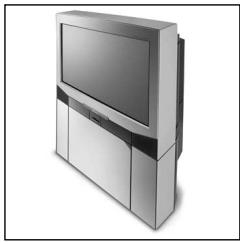
Consumer electronics
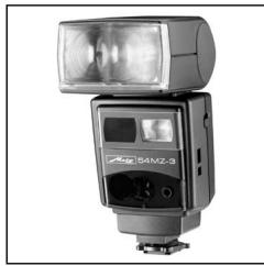
Photoelectronics
Plastics technology
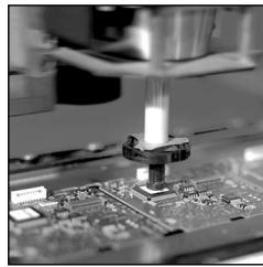
Industrial electronics
Metz. Always first class.

C E
703 47 0122.A3
D F NL GB I E
- Foreword
- Please also open the back cover page with the illustrations.
- MZ.. with standard foot 301
- Safety Instructions
- Preparing the flash unit for use
- Mounting the flash unit on the camera
- Mounting the standard foot or SCA adapter:
- Mounting the mecablitz:
- Dismantling the standard foot or SCA adapter:
- Power supply and battery warning indicator
- Replacing and charging the battery
- Switching the flashgun ON and OFF
- Operating concept
- Selecting and setting the flash mode TTL / A / M / (stroboscopic) 2)
- Selecting and setting the special functions
- Setting ISO / Zoom / Aperture ⑤ , "P" Partial Light Output and EV (Flash Exposure Correction)
- TTL flash mode
- Setting procedure for the TTL flash mode:
- Sub-modes of TTL flash mode
- Setting a sub-mode of TTL flash mode:
- Automatic flash mode
- Setting procedure for automatic flash mode:
- Automatic flash mode with an SCA 300 adapter or the SCA 301 standard foot:
- Sub-modes of the automatic flash mode
- Setting a sub-mode of the automatic flash mode:
- Manual flash mode
- Setting procedure for manual flash mode:
- Manual flash mode of the mecablitz with an SCA 3xx2 adapter:
- Setting partial light output:
- Deleting the set partial light output:
- Bounce flash
- Bounce flash with secondary reflector
- Bounce flash in automatic and TTL flash mode
- Bounce flash in manual flash mode
- Remote mode
- General
- Metz cordless TTL remote mode
- Setting procedure for Metz TTL remote controller operation:
- Setting procedure for Metz TTL remote slave operation:
- mecablitz unit without slave adapter (Fig. 4):
- Checking and changing the slave address on the 50 MZ-5 und 70 MZ-5:
- Changing the address setting on the 50 MZ-5 and 70 MZ-5:
- Deactivating the Metz TTL remote mode:
- Metz cordless auto remote mode
- Setting procedure for the Metz auto remote controller mode:
- this event do not forget to manually transfer the camera settings (ISO, f-stop and zoom position) to the mecablitz!
- Setting procedure for Metz auto remote slave mode:
- Assessing the overall lighting conditions in remote mode (not possible with 70 MZ-4)
- Fill-in flash in daylight
- Fill-in flash in TTL mode
- Example: Matrix-controlled fill-in flash (only for certain Nikon cameras):
- Example: 3D multi-sensor fill-in flash (only for certain Nikon cameras):
- Fill-in flash in automatic mode
- Example:
- Tip:
- Stroboscopic mode
- Correct exposure indication
- To trigger a test flash, hold the camera and flash unit in the same manner as for the actual shot!
- AF measuring beam
- Special functions
- Bleep function (acoustic alarm)
- Acoustic signal after the mecablitz has been switched on:
- Bleep signals after exposure:
- Bleep signals associated with settings in "A" automatic mode:
- Setting the bleep function:
- Deactivating the bleep function:
- Locking and unlocking the controls (key function) (not possible with 70 MZ-4)
- REAR - Second curtain synchronisation
- Switching on the REAR function:
- Deactivating the REAR function:
- Modelling light ML
- Setting the modelling light function:
- Deactivating the modelling light function when setting b) has been selected:
- Adapting the focal length to the camera format
- Setting procedure to adapt the focal length to the camera format:
- Flash bracketing ("Fb") (Fig. 8)
- ,Fb" flash bracketing in A mode:
- With some cameras "Fb" flash bracketing in A mode is not possible for technical reasons!
- Activating "Fb" flash bracketing:
- Re-establishing the basic setting
- Power-zoom reflector
- Changing the zoom position when using an SCA 3xx2 adapter and a data-transmitting camera:
- Returning to „AutoZoom“ mode:
- m - ft changeover
- Programme storage mode
- Setting procedure to store a programme:
- Calling a stored programme:
- The "Rapid" function
- Wide-angle diffuser
- Manual flash exposure correction
- Setting manual flash exposure correction:
- Deactivating manual flash exposure correction:
- Maintenance and care
- Forming the flash capacitor
- Technical data
- Glossary
- Optional extras
- Troubleshooting hints
- Disposal of batteries
- ①
- Do not touch the SCA contacts !
- Avertenza:
Brand : METZ
Model : MECABLITZ 70 MZ-4
Category : External Flash