
BEMPE 090 - Air conditioner BEKO - Free user manual and instructions
Find the device manual for free BEMPE 090 BEKO in PDF.


| Product Type | Portable Air Conditioner |
| Brand | Beko |
| Model | BEMPE 090 |
| Cooling Capacity | 9000 BTU/h |
| Operating Modes | Cooling, Fan, Dehumidification |
| Fan Speeds | 3 speed settings |
| Airflow Rate | 300 m³/h |
| Noise Level | 65 dB(A) maximum |
| Refrigerant | R290 |
| Power Supply | 220-240 V, 50 Hz |
| Power Consumption | 950 W |
| Current Draw | 4.2 A |
| Dimensions (W x D x H) | 350 x 350 x 700 mm |
| Net Weight | 25 kg |
| Exhaust Hose Length | 150 cm |
| Window Kit | Included |
| Drainage Type | Continuous drain option |
| Energy Efficiency Class | A |
| Temperature Setting Range | 16 °C to 31 °C |
| Timer | 24-hour programmable |
| Air Filter | Washable dust filter |
| Maintenance | Clean filter every 2 weeks |
| Safety Features | Overheating protection, auto restart |
| Spare Parts | Filter and exhaust hose are user-replaceable |
| Included Accessories | Window sealing plate, hose, remote control |
Frequently Asked Questions - BEMPE 090 BEKO
User questions about BEMPE 090 BEKO
0 question about this device. Answer the ones you know or ask your own.
Ask a new question about this device
Download the instructions for your Air conditioner in PDF format for free! Find your manual BEMPE 090 - BEKO and take your electronic device back in hand. On this page are published all the documents necessary for the use of your device. BEMPE 090 by BEKO.
USER MANUAL BEMPE 090 BEKO
Free match split type air conditioner
User Manual
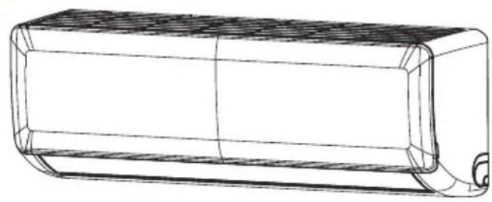
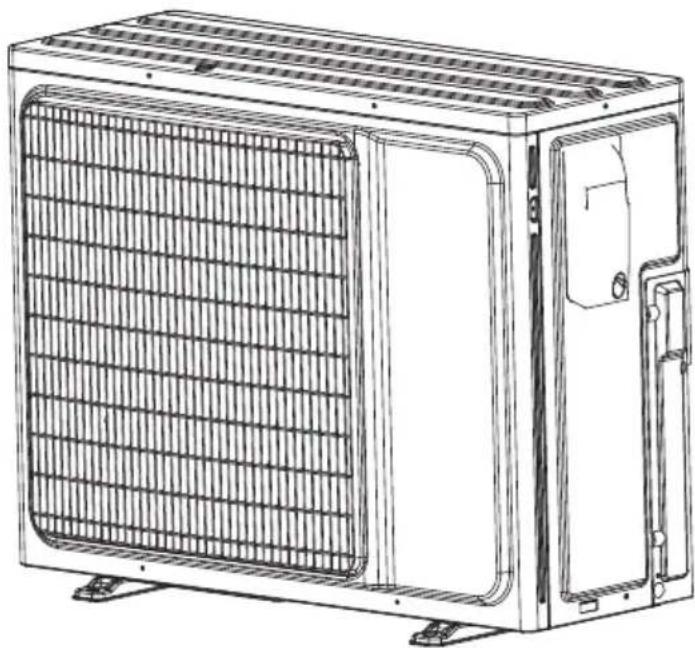
BEMPE 090 BEMPE 120 BEMPF 181 BEMPF 271
EN IT ES
Please read this user manual first!
Dear Customer,
Thank you for preferring a Beko product. We hope that you get the best results from your product which has been manufactured with high quality and state-of-the-art technology. Therefore, please read this entire user manual and all other accompanying documents carefully before using the product and keep it as a reference for future use. If you handover the product to someone else, give the user manual as well. Follow all warnings and information in the user manual.
Meanings of the symbols
Following symbols are used in the various section of this manual:

Important information or useful hints about usage.

Warning for hazardous situations with regard to life and property.

Warning to actions that must never perform.
Warning for electric shock.
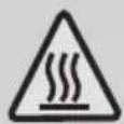
Warning for hot surfaces.
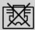
Do not cover it.

This symbol shows that the operation manual should be read carefully.
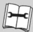
This symbol shows that a service personnel should be handling this equipment with reference to the installation manual.
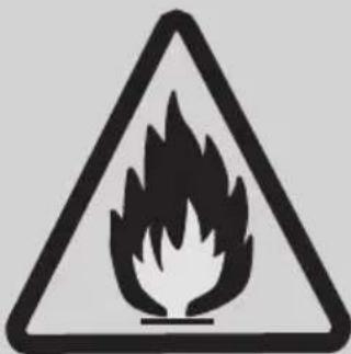
This symbol shows that this appliance used a flammable refrigerant. If the refrigerant is leaked and exposed to an external ignition source, there is a risk of fire.

This product has been produced in environmentally friendly, modern facilities
Contents
1 Safety instructions 5
2 WEEE warning 12
3 Operation 13
3.1 Remote controller 13
3.2 Usage....15
3.3 Fix batteries....16
3.4 Attention 16
4 Manual operation 17
4.1 Manual operation....17
4.2 Adjusting air flow direction....17
5 Notices 18
5.1 Checking before operation 18
5.2 Safety tips....18
5.3 Notices for R32 models....18
6 Care and maintenance 19
6.1 Cleaning....19
6.1.1 Cleaning the indoor unit....19
6.1.2 Cleaning air filter 19
6.2 Maintenance 19
7 Troubleshooting 20
8 Installation guide 26
8.1 Guide for customer 26
9 Notices of installation 27
9.1 Unpacking inspection 27
9.2 Safety principles for installing air conditioner....27
9.3 Requirements for installation position....27
9.4 Installation environment inspection 28
Contents
10 Selection of the installing position 29
10.1 Indoor unit....29
10.2 Outdoor unit....29
11 Installation of the indoor unit 31
11.1 Wall-mounted installation....31
11.2 Wall-mounted air conditioner unit 31
11.3 Check the water exhausting 32
12 Installation of the outdoor unit 34
13 Pipe connection 35
13.1 The form of pipe....36
13.2 Expelling the air in the pipes and the indoor unit 37
14 Electrical connection 38
15 Test running 39
16 Maintenance notice 40
16.1 Qualification requirements of maintenance personnel 40
16.2 Inspection of the site....40
16.3 Operating procedures 40
16.4 Inspection of cable 42
16.5 Leakage check of R32 refrigerant 42
16.6 Removal and vacuum pumping....43
16.7 Procedures of charging refrigerants 43
16.8 Scrap and recovery 44
17 Installation instructions 46
17.1 F-Gas instruction....46
18 Information servicing 47
19 Specifications 53
1 Safety instructions
Thank you for purchasing this air conditioner. This manual will provide you with information on how to operate, maintain, and troubleshoot your air conditioner. Following the instructions will ensure the proper function and extended lifespan of your unit.
Warning
- Ask an authorized dealer to install this air conditioner. Inappropriate installation may cause water leakage, electric shock, or fire.
- The warranty will be voided if the unit is not installed by professionals.
- If abnormal situation arises (like burning smell), turn off the power supply and call your dealer for instructions to avoid electric shock, fire or injury.
- Do not let the indoor unit or the remote control get wet. It may cause electric shock or fire.
- Do not insert fingers, rods or other objects into the air inlet or outlet. This may cause injury, since the fan may be rotating at high speeds.
- Do not use a flammable spray such as hair spray, lacquer or paint near the unit. This may cause fire or combustion.
- Do not touch the air outlet while the swing flap is in motion. Fingers might get caught or the unit may break down.
- Do not inspect the unit by yourself. Ask an authorized dealer to perform the inspection.
1 Safety instructions
- To prevent product deterioration, do not use the air conditioner for preservation purposes (storage of food, plants, animals, works of art, etc.).
- Do not touch the evaporator coils inside the indoor unit. The evaporator coils are sharp and may cause injury.
- Do not operate the air conditioner with wet hands. It may cause electric shock.
- Do not place items that might be affected by moisture damage under the indoor unit. Condensation can occur at a relative humidity of 80%.
- Do not expose heat-producing appliances to cold air or place them under the indoor unit. This may cause incomplete combustion or deformation of the unit due to the heat.
- After long periods of usage, check the indoor unit to see if anything is damaged. If the indoor unit is damaged, it may fall and cause injury.
- If the air conditioner is used together with other heating devices, thoroughly ventilate the room to avoid oxygen deficiency.
- Do not climb onto or place objects on top of the outdoor unit.
- Do not operate the air conditioner when using fumigant insecticides. The chemicals may become layered with the unit and endanger those who are hypersensitive to chemicals.
- Do not let children play with the air conditioner.
1 Safety instructions
Read safety precautions before installation
Incorrect installation due to ignoring instructions can cause serious damage or injury.
The seriousness of potential damage or injuries is classified as a warning.
Warning
- Carefully read the safety precautions before installation.
- In certain functional environments, such as kitchens, server rooms, etc., the use of specially designed air-conditioning units is highly recommended.
- Only trained and certified technicians should install, repair and service this air conditioning unit.
Improper installation may result in electrical shock, short circuit, leaks, fire or other damage to the equipment and personal property. - Strictly follow the installation instructions set forth in this manual. Improper installation may result in electrical shock, short circuit, leaks, fire or other damage to the equipment.
- Before you install the unit, consider strong winds, typhoons and earthquakes that might affect your unit and locate it accordingly. Failure to do so could cause the equipment to fail.
- After installation, ensure there are no refrigerant leaks and that the unit is operating properly. Refrigerant is both toxic and flammable and poses a serious health and safety risk.
1 Safety instructions
- If the supply cord is damaged, it must be replaced by the manufacturer or its agent or similarly qualified person in order to avoid hazard.
- The appliance shall state the insulation of a residual current device (RCD) having rated residual operating current not exceeding 30mA.
-
This appliance is intended to be used in household and similar applications such as
-
Staff kitchen areas in shops, offices and other working environments;
- farm houses;
- by clients in hotels, motels and other residential type environments;
- bed and breakfast type environments;
- Detail of type and rating of fuse, or rating of circuit breakers, please refer to the content of Chapter 14 - Electrical connection.
- This appliance can be used by children aged from 8 years and above if they have been given supervision or instruction concerning use of the appliance in a safe way and understand the hazards involved. Cleaning and user maintenance shall not be made by children unless they are aged from 8 years and above and supervised. Keep the appliance and its cord out of reach of children aged less than 8 years.
- Do not use means to accelerate the defrosting process or to clean, other than those recommended by the manufacturer.
1 Safety instructions
- The appliance shall be stored in a room without continuously operating ignition sources (for example: open flames, an operating gas appliance or an operating electric heater).
- Do not pierce or burn.
- The appliance shall be stored so as to prevent mechanical damage from occurring.
- Be aware that the refrigerants may not contain an odour.
- Compliance with national gas regulations shall be observed.
- Keep ventilation openings clear of obstruction.
- A warning that the appliance shall be stored in a well-ventilated area where the room size corresponds to the room area as specified for operation.
- Any person who is involved with working on or breaking into a refrigerant circuit should hold a current valid certificate from an industry-accredited assessment authority, which authorises their competence to handle refrigerants safely in accordance with an industry recognised assessment specification.
- Servicing shall only be performed as recommended by the equipment manufacturer.
Maintenance and repair requiring the assistance of other skilled personnel shall be carried out under the supervision of the person competent in the use of flammable refrigerants. - Appliance shall be stored in a well-ventilated area where the room size corresponds to the room area as specified for operation.
1 Safety instructions
- The appliance disconnection must be incorporated with an all-pole disconnection device in the fixed wiring in accordance with the wiring rules.
- Appliance shall be stored in a room without continuously operating open flames (for example an operating gas appliance) and ignition sources (for example an operating electric heater).
- Appliance shall be installed, operated and stored in a room with a floor area larger than X m2 (Please see the following form). The appliance shall not be installed in an unventilated space, if that space is smaller than X m2 (Please see the following form).
| Model (Btu/h) Amount of refrigerant to be charged (kg) | Maximum installation height (m) | Minimum room area (m2) |
| ≤30000 ≤2.048 2.2m 4 | ||
| ≤30000 ≤2.048 1.8m 4 | ||
| ≤30000 ≤2.048 0.6m 35 | ||
| 30000-48000 2.048-3.2 2.2m 7 | ||
| 30000-48000 2.048-3.2 1.8m 10 | ||
| 30000-48000 2.048-3.2 0.6m 80 | ||
| >48000 >3.6 2.2m 9 | ||
| >48000 >3.6 1.8m 13 | ||
| >48000 >3.6 0.6m 80 |
1 Safety instructions

Note about fluorinated gasses
- This air-conditioning unit contains fluorinated gasses. For specific information on the type of gas and the amount, please refer to the relevant label on the unit itself.
- Installation, service, maintenance and repair of this unit must be performed by a certified technician.
- Product uninstallation and recycling must be performed by a certified technician.
- If the system has a leak-detection system installed, it must be checked for leaks at least every 12 months.
- When the unit is checked for leaks, proper record-keeping of all checks is strongly recommended.
2 WEEE warning
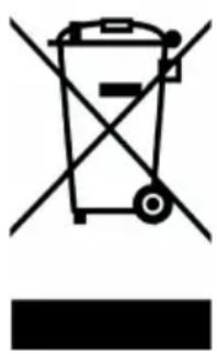
This symbol indicates that this product shall not be disposed with other household wastes at the end of its service life.
Used device must be returned to official collection point for recycling of electrical and electronic devices.
To find these collection systems please contact to your local authorities or retailer where the product was purchased.
Each household performs important role in recovering and recycling of old appliance.
Appropriate disposal of used appliance helps prevent potential negative consequences for the environment and human health.
3 Operation
3.1 Remote controller
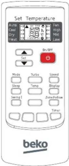

Note:
All the figures above are the displays after being initially electrified or re-electrified after power off. In actual operations, the remote controller screen displays related items only.
-
[On/Off] button
You can start or stop the air-conditioner by pressing this button. -
[Speed] button
You can select fan speed as the following:
![graph LR A["Low Med High Auto"] --> B["Step 1"] B --> C["Step 2"] C --> D["Step 3"]](/content/2026/08/1617907/images/21e9798fc2e37ec0dfbf27b7a45ab66ae6f960dee1c550380451498609afc6b1.jpg)
-
[Swing] button
Press this button to activate up/down swing and press it again to fix the swing position. -
[Zone Follow] button
Press this button to set the temperature display on the remote controller to ambient temperature and press this button again to set it to preset temperature.
- [Timer] button
Setting the "On" timer time:
a. When remote controller is at off state, press "Timer" button, the LCD displays "Timer On" and the timer time, the range of setting time is 0.5h to 24h.
3 Operation
b. You can press the "or" button to adjust the timer time, each touch will be set time to increase or reduce 0.5 h before 10 hours ago, after ten hours will be set time to increase or reduce 1 h per pressing, to enable your required timer.
c. Press "Timer" button again, to set the timer on function.
d. You can set another function to insure the suitable state after air conditioner turn on (including mode, temperature, swing, fan speed and etc). The LCD will display all your setting and keep it, when the timer reach to the set time, the air conditioner will be working according to your set automatically.
Setting the "Off" timer time:
a. When remote controller is at on state, press "Timer" button, the LCD displays "Timer Off" and the timer time, the range of setting time is 0.5h to 24h.
b. You can press the "or" button to adjust the timer time, each touch will be set time to increase or reduce 0.5h before 10 hours ago, after ten hours will be set time to increase or reduce 1h per pressing, to enable your required timer.
c. Press "Timer" button again, to set the timer off function.
- [▲or [ ] button
Press the "+" or "-" button, you can set the temperature range from 16°C to 32°C, Display will change when you touch the button.
- [Mode] button
Which enables you to select different operation mode, after each pressing, the operation mode will be changed. It shows in the following display.
Auto → Cool → Dry → Heat → Fan → Auto

Note: Cold wind type has no heating function.
-
[Sleep] button
-
Press the Sleep button, the sleeping indicator light of indoor unit flashes on.
- After the setting of sleeping mode, the cooling operation enables the set temperature to increase 1° C after 1 hour and another 1° C automatically after 1 hour.
- After the setting of sleeping mode, the heating operation enables the set temperature to drop 2° C after 1 hour and another 2° C automatically after 1 hour.
- The air-conditioner runs in sleeping mode for 7 hours and stops automatically.

Note: Press the Mode or On/Off button, the remote controller clears sleeping mode away.
3 Operation
3.2 Usage
Automatic operation mode
- Press the On/Off button, the air-conditioner starts to operate.
- Press the Mode button, select the automatic operation mode.
- Press the Speed button, you can select fan speed. You can select fan speed from Low, Mid, High, Auto.
- Press the button again, the air-conditioner stops.
• Cooling/Heating operation mode (cold wind type has no heating function)
- Press the On/Off button, the air-conditioner starts to operate.
- Press the Mode button, select the Cooling or Heating operation mode.
- Press the "or" button, set the temperature, temperature can be set at 1° C difference range from 16 - 32° C .
- Press the Speed button, you can select fan speed. You can select fan speed from Low, Mid, High, Auto.
- Press the button again, the air-conditioner stops.
- Fan operation mode
- Press the On/Off button, the air-conditioner starts to operate.
- Press the Mode button, select the Cooling or Heating operation mode.
- Press the Speed button, you can select fan speed. You can select fan speed from Low, Mid, High.
- Press the button again, the air-conditioner stops.

Note: In the circulation operation mode, to set the temperature is noneffective.
- Drying operation mode
- Press the On/Off button, the air-conditioner starts to operate.
- Press the Mode button, select the Dry operation mode.
- Press the "▲or" button, set the temperature, temperature can be set at 1°C difference range from 16-32°C.
- Press the Speed button, you can select fan speed. You can select fan speed from Low, Mid, High, Auto.
- Press the button again, the air-conditioner stops.

Note: This manual introduces function for all of the remote control, maybe you press one button without any reaction, well, the air-conditioner you bought hasn't this function.
3 Operation
3.3 Fix batteries
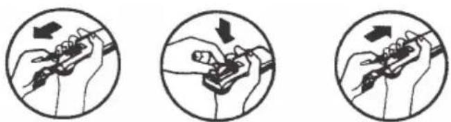
- Slide open the cover according the direction indicated by arrowhead.
- Put into two brand new batteries (7#), position the batteries to right electric poles (+&-).
- Put back the cover.
3.4 Attention
- Aim the remote controller towards the receiver on the air-conditioner.
- The remote controller should be within 8 meters away from the receiver.
- No obstacles between the remote controller and receiver.
- Do not drop or throw the remote controller.
- Do not put the remote controller under the forceful sun rays or heating facilities and other heating sources.
- Use two 7# batteries, do not use the electric batteries.
- Take the batteries out of remote controller before stop its using for long.
- When the noise of transmitting signal can t be heard indoor unit or the transmission symbol on the display screen does not flare, batteries need be replaced.
- If reset phenomenon occurs on pressing the button of the remote controller, the electric quantity is deficient and new batteries need to be substituted.
- The waste battery should be disposed properly.
4 Manual operation
4.1 Manual operation
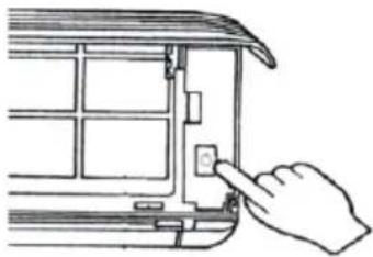
When the remote controller does not work or can not be found, please follow these steps:
- As the unit is operating, you can press the "Auto button" to stop operating.
- As the unit is stopping, you can press the "Auto button" to start operating.
4.2 Adjusting air flow direction
1. Adjusting horizontal air flow manually.
Use your hands to move the vertical airflow vane and change the horizontal wind direction.
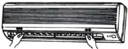

Note:
a. Adjust the horizontal air flow direction before the air-conditioner starts. Don't insert your finger into air intake or outlet vents when the air-conditioner is operating.
b. For appliance with auto pendulum wind function, please refer to "air conditioner remote controller instruction" for how to adjust horizontal air flow.
2. Adjusting vertical air flow direction (up-down)
Refer to "air conditioner remote controller instruction" for how to adjust vertical airflow direction through adjusting the horizontal airflow vane by remote controller.

Note:
- Adjust the vertical air flow direction by remote controller. When you adjust the horizontal airflow vane by hand, the machine may cause problem.
- Manual operation can be used temporarily in case you can not use remote controller or its batteries are exhausted.
- When the air-conditioner stops, the horizontal wind vane will close the wind outlet of air conditioner.
5 Notices
To prevent injury and property damage, Please pay attention to these following before operating the air conditioner.
5.1 Checking before operation
- Make sure that the earth wire is connected safely and reliably.
- Make sure the filter net is properly fixed.
- Make sure that air outlet and inlet are not blocked.
- Please clean the filter before starting the air-conditioner referring to page 19 to "6.1 Cleaning" for how to operate.
- Check to see whether the outdoor install bracket is damage. If yes, please contact our Service center locally.
5.2 Safety tips
In order to use the air conditioner properly, please refer to its working temperature range. Otherwise, indoor unit automatic protection function may be activated, cooling or heating efficiency will be weakened.
The air-conditioner may not run normally in the following situation:
| Cooling | Outdoor | >52°C |
| <-10°C | ||
| Indoor <18°C |
| Heating | Outdoor | >24°C |
| <-15°C | ||
| Indoor >30°C |
5.3 Notices for R32 models
This product contains fluorinated greenhouse gases.
Refrigerant leakage contributes to climate change. Refrigerant with lower global warming potential (GWP) would contribute less to global warming than a refrigerant with higher GWP, if leaked to the atmosphere. This appliance contains a refrigerant fluid with a GWP equal to [675]. This means that if 1 kg of this refrigerant fluid would be leaked to the atmosphere, the impact on global warming would be [675] times higher than 1 kg of CO 2 , over a period of 100 years. Never try to interfere with the refrigerant circuit yourself or disassemble the product yourself and always ask a professiona.
6 Care and maintenance
6.1 Cleaning
6.1.1 Cleaning the indoor unit
- Turn off the air-conditioner and remove the electrical plug from the outlet.
- Wipe the indoor unit with dry cloth or wet cloth which is dipped by cold water.

Note:
- Don't use water above 45°C to wash the panel, or it could cause deformation or depigment.
- Don't use thinner, polishing powder, benzene and other volatile chemicals.
- Don't use liquid or corrosive detergent clean the appliance and don't splash water or other liquid onto it, otherwise, it may damage the plastic components, even cause electric shock.
6.1.2 Cleaning air filter
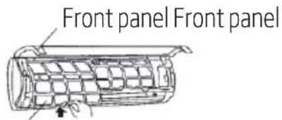
Air filter Air filter
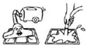
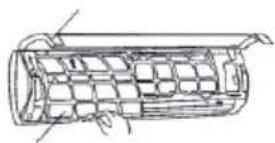
- Raise up the front panel of indoor unit until it suddenly stop, then raise up the protruded part of air filter, and then take it out.
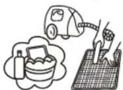
- Use a vacuum cleaner or wash them with water, then dry it in the shade.
- Reinsert the air filter into the indoor unit until being entirely fixed, then close the front panel.
6.2 Maintenance
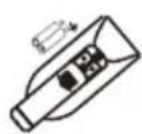
- Select "Fan" operation mode, make the air conditioner run a short time to dry.

- Take out the batteries from the remote controller.
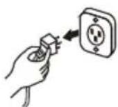
- Turn off the air conditioner and cut off the power supply.
- Clean air filters and other parts.
7 Troubleshooting
Check the following before requesting on service centre of BEKO if the malfunction occurs.
| Phenomenon Troubleshooting | |
| Air conditioner dose not operate at all | Has the power been shut down?Is the wiring loose?Is the voltage higher than 1.1 times of max rated voltage or lower than 0.9 times of min rated voltage?Is the fuse burnt?Does it reach the set time for start up? |
| Remote controller is not available | Is the remote controller out of effective distance to the indoor unit?Is the battery exhausted?Are there any obstructions between the controller and the signal receptor? |
| Cooling (Heating) efficiency is not good | Is the setting temperature suitable?Is the air inlet or outlet obstructed?Are air filter dirty?Is indoor fan speed set at low speed?Is there any heat source in your room? |
| Indoor unit does not operate immediately when the air conditioner is restarted | Once the air conditioner is stopped, it will not operate in approximately 3 minutes to protect itself. |
| There is unusual smell blowing from the outlet after operation is started. | This is caused by the odour in the room permeated from building material, furniture, or smoke. |
| Sound of water flow can be heard during cooling operation | This is caused by the refrigerant flowing inside the unit. |
| Mist is emitted during cooling operation. | Because the air of the room is cooled down rapidly by the cold wind and it looks like the fog. |
| Mist is emitted during heating operation. | This generate due to moisture in defrosting process. |
| A low hissing sound is caused by the refrigerant flowing. | Low noise can be heard during operationA low squeak sound is caused by the deformation of plastic due to temperature. |
7 Troubleshooting
| Mode interfereFor the reason that all indoor units use one outdoor unit, outdoor unit can only run with same mode (cooling or heating), so, when the mode you set is different from the mode, that outdoor is running with, mode interfere occurs. Following shows the mode interfere scene. | cooling dry heating fancooling --normal √ × √ √dry --mode interfere√ × √ ×heating × × √ √fan √ √ √ √outdoor unit always run with the mode of first indoor unit that turned on. When the setting mode of following indoor unit is interfere with it, 3 beeps would be heard, and the indoor unit interfered with the normal running units would turn off automatically. |
Fault code
When the air conditioner fails, the LED light on indoor display board will show the corresponding fault code according to different fault.

Note: For the unit with digital tube, it will show the corresponding fault codes; for the unit no digital tube only LED light, it will only show the corresponding fault codes with timer light.
Specific correspondis as follows:
Wall mounted
| Fault code | Fault description Causes of possible failure | |
| E1 | Fault with the room temperature sensor on the N # indoor unit | Damage of the room temperature sensor on the indoor unit |
| Poor contact of the room temperature sensor on the indoor unit | ||
| Damage of wiring of the room temperature sensor on the indoor unit | ||
| Damage of the main PCB on the indoor unit | ||
| E2 | Fault with the Defrosting/Condenser Temperature Sensor in Outdoor | Damage of the temperature sensor on the outdoor unit |
| Poor contact of the temperature sensor on the outdoor unit | ||
| Damage of wiring of the temperature sensor on the outdoor unit | ||
| Damage of the main PCB on the outdoor unit | ||
| E3 | Fault with the temperature Sensor in the Middle of N # indoor evaporator | Damage of the temperature sensor on the indoor unit |
| Poor contact of the temperature sensor on the indoor unit | ||
| Damage of wiring of the temperature sensor on the indoor unit | ||
| Damage of the main PCB on the indoor unit | ||
7 Troubleshooting
| E4 | Fault with the Fan motor of N # indoor unit | Low voltage |
| Poor wiring | ||
| Damage of the main PCB on the indoor unit | ||
| Damage of the motor | ||
| E5 | Communication error between the outdoor unit and the N # indoor unit | Damage of the main PCB on the indoor unit |
| Damage of the main PCB on the outdoor unit | ||
| Poor wiring | ||
| E8 | Communication error between the display board and main PCB of the indoor unit | Damage of the main PCB on the indoor unit |
| Damage of the display board on the indoor unit | ||
| Poor wiring | ||
| F1 Module protection failure | Compressor damage | |
| Compressor IPM Module damage | ||
| System blockage | ||
| F0 | Fault with the Fan motor of outdoor unit | Damage of motor |
| F2 | Compressor drive PFC protection | Damage of the PFC circuit components |
| Reactor damage | ||
| F3 Compressor protection failure | Compressor power line not connected | |
| Compressor sequence connection error | ||
| Damage of compressor | ||
| System blockage | ||
| F4 | Fault with the discharge temperature sensor | Damage of the discharge temperature sensor on the outdoor unit |
| Poor contact of the discharge temperature sensor on the outdoor unit | ||
| Damage of wiring of the discharge temperature sensor on the outdoor unit | ||
| Damage of the main PCB on the outdoor unit | ||
| F5 | Temperature protection of compressor top cover | Damage of compressor top cover switch |
| System blockage | ||
| F6 | Fault with the Environmental temperature sensor on the outdoor unit | Damage of the Environmental temperature sensor on the outdoor unit |
| Poor contact of the Environmental temperature sensor on the outdoor unit | ||
| Damage of wiring of the Environmental temperature sensor on the outdoor unit | ||
| Damage of the main PCB on the outdoor unit | ||
7 Troubleshooting
| F7 | Fault with the over-voltage or low voltage protection | Excessive input voltage |
| Lower input voltage | ||
| F8 | Communication error between the driver PCB and main PCB of the outdoor unit | Damage of the driver PCB on the outdoor unit |
| Damage of the main PCB on the outdoor unit | ||
| Poor wiring | ||
| F9 | Fault with the outdoor unit EEPROM | Chip damage |
| FA | Fault with the suction temperature sensor | Damage of the suction temperature sensor on the outdoor unit |
| Poor contact of the suction temperature sensor on the outdoor unit | ||
| Damage of wiring of the suction temperature sensor on the outdoor unit | ||
| Damage of the main PCB on the outdoor unit | ||
| H1 | Fault with the drainage on N# Indoor unit | Float switch disconnected or poor wiring |
| Error setting of model parameters | ||
| Drain plug | ||
| Damage of the pump | ||
| H2 | Communication error between the wired controller and main PCB of the N# indoor unit | Poor wiring |
| Damage of the wired controller | ||
| Damage of the main PCB on the indoor unit | ||
| H3 | Fault of temperature sensor at N # evaporator inlet | Damage of temperature sensor at N # evaporator inlet |
| Poor contact of temperature sensor at N # evaporator inlet | ||
| Damage of wiring of temperature sensor at N # evaporator inlet | ||
| Damage of the main PCB on the outdoor unit | ||
| H4 | Fault of temperature sensor at N# evaporator outlet | Damage of temperature sensor at N# evaporator outlet |
| Poor contact of temperature sensor at N# evaporator outlet | ||
| Damage of wiring of temperature sensor at N# evaporator outlet | ||
| Damage of the main PCB on the outdoor unit | ||
| H5 | Protection lower temperature discharge | Temperature sensor shedding |
| Damage of the main PCB on the outdoor unit | ||
| H6 | Low pressure switch protection | Lack of the refrigerant |
| Stop valve unopened | ||
| Damage of low pressure switch | ||
| H7 Low pressure protection | Lack of the refrigerant | |
| Heat exchanger mismatch | ||
7 Troubleshooting
| H8 Fault of four way valve | Damage of four-way valve | |
| Damage to coil of four-way valve | ||
| H9 | Inter-computer communication line connection fault | / |
| L0 | Overvoltage and undervoltage protection of indoor DC motor | Excessive input voltage |
| Lower input voltage | ||
| L1 | Overcurrent protection of compressor | Damage of compressor |
| System mismatch | ||
| L2 Compressor operation failure | Damage of compressor | |
| System mismatch | ||
| L3 | Phase-absence protection of compressor | Damage of compressor |
| Compressor power line not connected | ||
| L4 | IPM Fault of compressor Drive module | Compressor drive module damage |
| L5 | Compressor drive PFC hardware protection | Damage of the PFC circuit components |
| Reactor damage | ||
| L6 | Compressor drive PFC software protection | Excessive running current of the unit |
| Voltage drops abruptly in operation | ||
| L7 | AD Abnormal protection for compressor current detection | Sensor damage of compressor IPM module |
| L8 | Compressor superpower protection | Sampling resistance damage |
| Excessive operating power of compressor | ||
| L9 IPM | Temperature sensor fault | Compressor IPM Module sensor damage |
| Poor contact between compressor IPM module and radiator | ||
| LA Compressor start failure Compressor | Power line not connected | |
| LC | PFC Current Detection AD Abnormal Protection | Failure of PFC Module Circuit Device |
| LD | AD Abnormal Protection for Outdoor DC Fan Current Detection | Failure of DC Fan Module Circuit Device |
| LE | Phase-lacking protection of outdoor DC fans | DC fan line not connected |
| Three wires of DC fan are disconnected | ||
| LF | Outdoor DC Fan Out-of-step Protection | DC motor failure |
| High Speed of DC Fan | ||
| System dirty blocking | ||
| LH | IPM Protection of Outdoor DC Fan | The IPM Device of DC Motor is Bad |
7 Troubleshooting
| P8 | AC Over-current Protection of the Whole Machine | Excessive running current of the unit |
| Voltage drops abruptly during operation | ||
| P5 | Protection high temperature discharge | Lack of the refrigerant |
| Stop valve unopened | ||
| Damage of the main PCB on the outdoor unit | ||
| P4 | High Temperature Protection for Refrigeration Outdoor | Poor outdoor heat transfer |
| P6 High Temperature Protection Over | temperature in indoor heat exchanger | |
| p7 | Indoor anti-freezing protection | Dirty Blockage of Heat Exchanger in Refrigeration Indoor Unit |
| Blockage of Internal Fan | ||
| P2 | High Pressure Switch Protection | System dirty blocking |
| Damage of High Pressure Switch | ||
| P3 | Protection of System Lack of Fluid | Lack of refrigerant |
| Globe Valve Not Opened | ||
| 5E | Communication error between the outdoor unit and the indoor unit | Damage of the main PCB on the indoor unit |
| Damage of the main PCB on the outdoor unit | ||
| Poor wiring | ||
8 Installation guide
8.1 Guide for customer
- Please read the instructions carefully before installation of the air-conditioner.
- The installation should be carried out by specialists.
- Installation the air-conditioner and connecting the pipe and wires must be strict to reference the instructions.
- The wiring must be done by qualified electrician according to the electrical safety requirements.
- The customer should have a qualified power supply which coincides with the tag of air conditioner, the normal voltage should be in the range of 90-110% of its rated voltage.
- The air conditioner must be well grounded, the switch of the main power of air-conditioner must be reliably grounded.

Warning:
- The air conditioner must be installed on well strong supporter.
- The appliance shall be installed in accordance with national wiring regulations.
- Fix the machine firmly, otherwise it will produce abnormal noise and vibration.
- Install the outdoor unit in the place where it wouldn't disturb your neighbour.
- The method of connection of the appliance to the electrical supply and inter connection of separate components, please see the electric diagram which stick on the machine.
- If the power supply cord is damaged, it must be replaced by the manufacture or its service agent or a similar qualified person.
- After installation, the power plug should be easily reached.
9 Notices of installation
9.1 Unpacking inspection
- Open the box and check air conditioner in area with good ventilation (open the door and window) and without ignition source.

Note: Operators are required to wear anti-static devices.
- It is necessary to check by professional whether there is refrigerant leakage before opening the box of outdoor machine; stop installing the air conditioner if leakage is found.
- The fire prevention equipment and anti-static precautions shall be prepared well before checking. Then check the refrigerant pipeline to see if there is any collision traces, and whether the outlook is good.
9.2 Safety principles for installing air conditioner
• Fire prevention device shall be prepared before installation.
- Keep installing site ventilated.(open the door and window)
- Ignition source, smoking and calling is not allowed to exist in area where R32 refrigerant located.
- Anti-static precautions in necessary for installing air conditioner, e.g. wear pure cotton clothes and gloves.
- Keep leak detector in working state during the installation.
- If R32 refrigerant leakage occurs during the installation, you shall immediately detect the concentration in indoor environment until it reaches a safe level. If refrigerant leakage affects the performance of the air conditioner, please immediately stop the operation, and the air conditioner must be vacuumed firstly and be returned to the maintenance station for processing.
- Keep electric appliance, power switch, plug, socket, high temperature heat source and high static away from the area underneath sidelines of the indoor unit.
- The air conditioner shall be installed in an accessible location to installation and maintenance, without obstacles that may block air inlets or outlets of indoor/outdoor units, and shall keep away from heat source, inflammable or explosive conditions.
- When installing or repairing the air conditioner and the connecting line is not long enough, the entire connecting line shall be replaced with the connecting line of the original specification; extension is not allowed.
- Use new connection pipe, unless re-flaring the pipe.
9.3 Requirements for installation position
- Avoid places of inflammable or explosive gas leakage or where there are strongly aggressive gases.
9 Notices of installation
- Avoid places subject to strong artificial electric/magnetic fields.
- Avoid places subject to noise and resonance.
- Avoid severe natural conditions (e.g. heavy lampblack, strong sandy wind, direct sunshine or high temperature heat sources).
- Avoid places within the reach of children.
- Shorten the connection between the indoor and outdoor units.
- Select where it is easy to perform service and repair and where the ventilation good.
- The outdoor unit shall not be installed in any way that could occupy an aisle, stairway, exit, fire escape, catwalk or any other public area.
- The outdoor unit shall be installed as far as possible from the doors and windows of the neighbors as well as the green plants.
9.4 Installation environment inspection
- Check nameplate of outdoor unit to make sure whether the refrigerant is R32.
- Check the floor space of the room. The space shall not be less than usable space(5m 2 ) in the specification. The outdoor unit shall be installed at a well-ventilated place.
- Check the surrounding environment of installation site: R32 shall not be installed in the enclosed reserved space of a building.
- When using electric drill to make holes in the wall, check first whether there is pre-buried pipeline for water, electricity and gas. It is suggested to use the reserved hole in the roof of the wall.
10 Selection of the installing position
10.1 Indoor unit
- There is no heating and steaming source nearby.
- No obstacles for installing position nearly.
- Keep good air circulation.
- Convenient to adopt measures to reduce noises.
- Do not install them near the doorway.
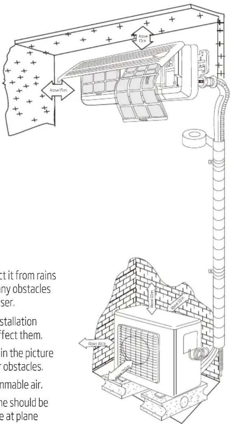
• Make sure to have the distance between the ceiling, wall, furniture and other obstacles.
• 2 meters high above the floor.
10.2 Outdoor unit
- In case that you put up a canopy to protect it from rains and sunrays, pay attention not to cause any obstacles for the heating dispersion for the condenser.
- Do not grow animals or plants near the installation location for the cold and hot air out will affect them.
• Make sure to have the distance specified in the picture between ceiling, wall, furniture and other obstacles. - Stay away from heating source and inflammable air.
- The installation base and supporting frame should be strong and secure. The machine should be at plane surface.
10 Selection of the installing position
You can adjust the vertical location of indoor and outdoor units according to the installation requirement. If the outdoor unit is installed higher than indoor units and H1, H2, H3, H4, H5 > 7m, please set the oil bend every 3 meters on the vertical gas pipe. In other cases don't need to install oil bend.
![graph TD A["Indoor unit A"] --> B["Indoor unit B"] B --> C["Indoor unit C"] C --> D["Indoor unit D"] D --> E["Indoor unit E"] E --> F["Indoor unit E"] style A fill:#f9f,stroke:#333 style B fill:#ccf,stroke:#333 style C fill:#cfc,stroke:#333 style D fill:#fcc,stroke:#333 style E fill:#cff,stroke:#333…](/content/2026/08/1617907/images/894faf06189d78cf4346526c0c2c29f0293a52cf48d1d5158fd74b905abfcece.jpg)

Note: All the requirements below should be met at the same time:
L1+L2≤40mL1+L2+L3≤60mL1+L2+L3+L4≤80mL1+L2+L3+L4+L5≤ 8 0 mH≤10m
H 1, H 2, H 3, H 4, H 5 ≤ 1 5 m
Each machine's standard piping is 7.5 meters, if the total liquid pipe length of indoor units more than 7.5*N meters, additional refrigerant is need. N = 1,2,3,4,5
PIPE LENGTH AND HEIGHT DIFFERENCE
| Pipe length | Up to 7.5*N m No additional charge is required |
| Exceeding 7.5*N m Additional charge is required. | |
| Refrigerant to be added 20g/m x | (refrigerant piping length(m)-7.5*N) |
11 Installation of the indoor unit
11.1 Wall-mounted installation
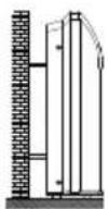

Warning: The unit must be horizontal or declined to drain hose when finished installation.
11.2 Wall-mounted air conditioner unit
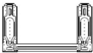
- First make changes to wall and make sure that is hard and secure. Using four "+" type screws to fasten the installation board onto the wall. Keep the mounting plate horizontal during installation, without slope. Otherwise it might cause water drops when air-conditioner is running cooling operation.
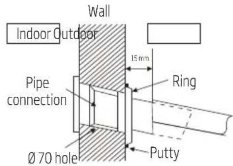
- Drilling 70mm diameter pipe hole at the left down or right down side of the installation board. The hole shall slant outward slightly.
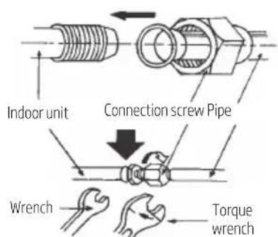
- Pull out the indoor unit pipes after detached the fixed parts on them. Connect the interconnected pipes to the indoor unit: point to the center of pipe and fasten the connection screw at first by hand and then by wrench until you hear the "Click" sound. Fastening direction is shown in the right picture. Using torque is shown in the following table.
11 Installation of the indoor unit
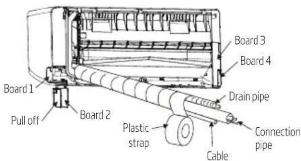
- Before installation, confirm connection pipes' direction. Remove the board 1 and board 2 on the correct connecting side. Press connection pipes to the board gap, then install board 2 to the original location. If connection pipes are on the other side, install them as above.
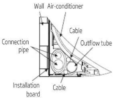

Note: The installed air-conditioner won't be tightly appressed to the wall if that is not arranged shown in the picture. The outflow tube must be in the bottom and the highest point of it can not exceed the position of water basin.
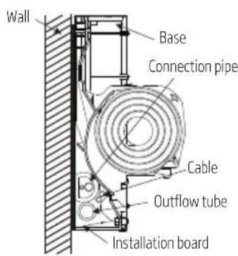
11.3 Check the water exhausting
-
Take off the frame the unit cover. Take off the front frame for maintenance according to the following steps:
-
Turn perpendicular airflow direction handle from "I" to horizontal direction.
- As shown in the picture on the below, take off two covers from the front frame and then unfasten two fixture screws.
• Pull the front frame towards yourself and take it off.
11 Installation of the indoor unit
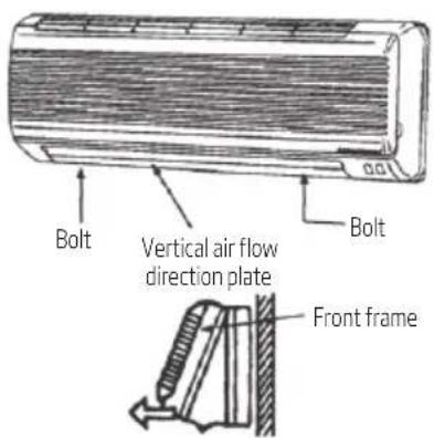
In case that put the front frame back, turn the perpendicular airflow direction handle from "I" to horizontal, then proceed according to the third and the second steps.
You should check whether the front frame is firmly inside the fixture groove on the top.
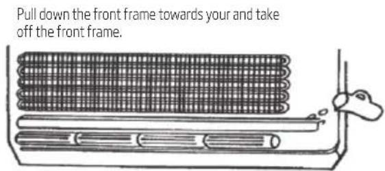
- Check the water exhausting.
• Put a cup of water into groove.
- Check whether the water flow through the water exhausting hole.
12 Installation of the outdoor unit
• The outdoor unit must be firmly fixed to avoid falling in the strong wind.
- Please install the air conditioner on the cement base according to the belowing drawing.
- If it will be installed at seaside or at a place high above the ground and with strong wind, the AC should be installed against the wall to ensure the normal operation of the fan and the blocking plate should be used.
- If it will be installed in type, the structure of the mounting surface should be made of solid stick, cement or materials with equivalent strength, and be of enough bearing capacity. Otherwise, measures such as reinforcement, support or vibration damping should be adopted.
Installation outdoor unit bolt
| Model Unit size A (mm) B (mm) | |||
| 1 drive 2 80 | 0x315x545 545 315 | ||
| 1 drive 3 83 | 4x328x655 540 335 | ||
| 1 drive 4 | 985x395x808 675 409 | ||
| 1 drive 5 | |||
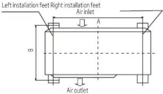
Outdoor Unit
13 Pipe connection
- Connect the pipe to the unit: point to the center of pipe and fasten by wrench until it is tightly fastened, the fastening direction is in the following picture.
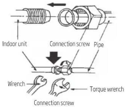
| The size of pipe Torque |
| ∅6.35mm (1/4") 18N.m |
| ∅9.52mm (3/8") 42N.m |
| ∅12.7mm (1/2") 55N.m |
| ∅15.88mm (5/8") 75N.m |

Note: Carefully check if there is any damage of joints before installation. The joints shall not be reused, unless after re-flaring the pipe.
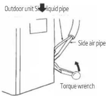
- Pointing towards the center of pipe, fasten the screw with strength.
- Wrench the screw in the end until you hear the "Click" sound.
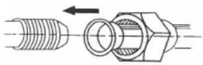
Refer the direction to the picture
13 Pipe connection
13.1 The form of pipe
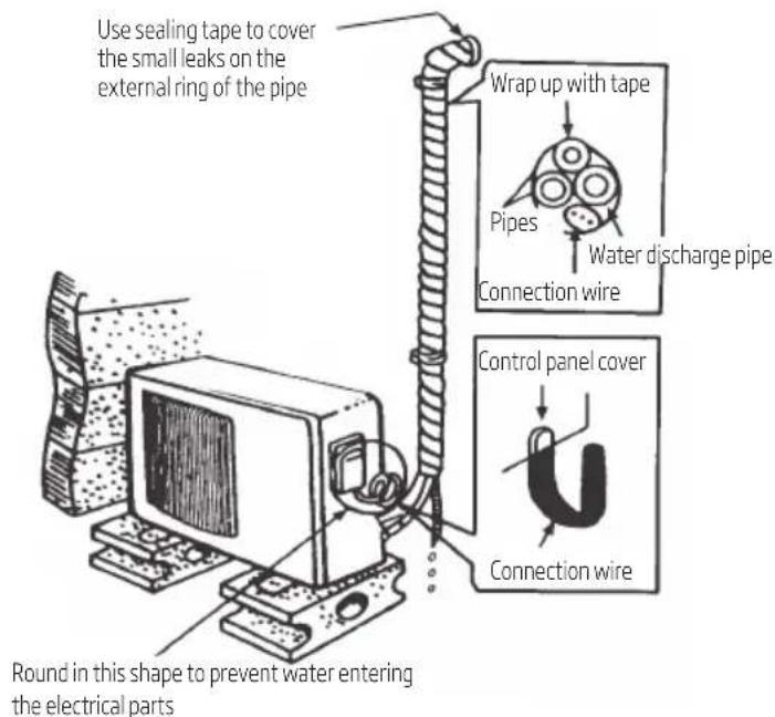
- Wrap up all pipe, water discharge and connection wire from top to below.
• Cover the connection and fix them with two plastic rings. - Wrap up the pipes with tape alongside the wall and fix them to the wall with clips. These steps are usually adopted when outdoor unit is installed below the indoor unit.
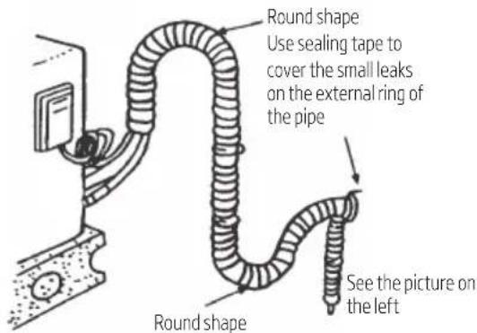
- In case that you want to have additional water discharge pipe, the end of pipe should be within certain distance towards to surface (don't let it under the water. Fix it onto the wall so it won't be swayed by the wind).
- Wrap the pipes and connection wire well from below to top.
- Wrap up the pipes that are rounded up by the wall corners in the way shown in the picture so it can prevent water entering the room.
• Use clips or other fixture to fasten the pipes to the walls.
13 Pipe connection
13.2 Expelling the air in the pipes and the indoor unit
Exclusive R32 refrigerant pump must be used in making R32 refrigerant vacuum.
- Connect the pipes of indoor units and outdoor unit according to the figure below, and tighten all the bell coupling nuts of indoor and outdoor to prevent leakage.
- Connect the cut-off valves, charge hose, manifold valve, vacuum pump as the figure below.
- Please fully open the manifold valve handle Lo and Hi, and do the vacuum processing, vacuum should be running more than 15 minutes, make sure the vacuum gauge indicates the pressure has reached -0.1MPa (-76cmHg);
- After completion of vacuum processing, use the hex wrench to open a little the liquid valve of unit A and unit B, and then quickly remove the hose of gas valve (remove the hose to prevent air from entering the system);
- Open all the cut-off valve and check the connecting mouth of indoor and outdoor, then cover the cut-off valves after confirm there is no leak.
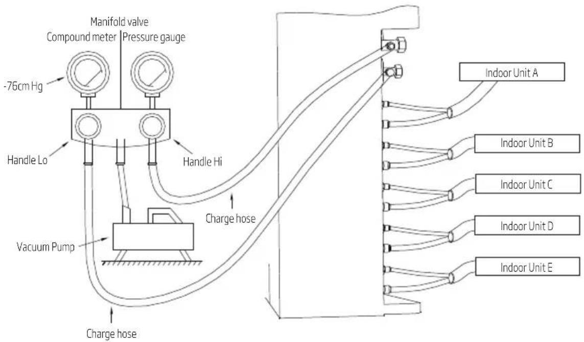
14 Electrical connection
The wiring cable specification that is needed in the installation:
| Wiring Type Cross-sectional area (mm 2 ) Switch/fuse nominal value (A) | ||
| Power line(3 core wire) | 2.5 (14k/18k/21k/27k)4 (36k/42k) | 32/25 |
| Connection wire(4 core wire) | 1.5 / | |
Connection wire between indoor and outdoor: The outdoor unit has three(AM2) /four(AM3) terminal boards, they are connected to power supply, the indoor unit A, the indoor unit B, the indoor unit C. Specific connection method as shown below:
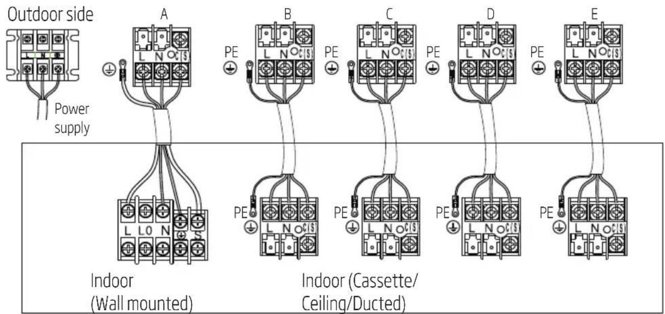
Indoor Side

Note:
- The connection wire of indoor units should be connected to the corresponding terminal board, that is the power core of A can't connected to the outdoor terminal board for B, otherwise it will cause the unit failure or even damage the units.
- Connect the grounded wire correctly, otherwise will cause the malfunction of some electrical component and shock or fire indeed.
- Don't reverse the power polarity.
- Must fix the screw nail of the firmly wire, then drag the wire lightly, confirmation whether it's firmly.
• If there is a connector, connect it directly.
15 Test running
• Make sure that pipes and wires are connected.
• Make sure that liquid side valve and air side valve both are completely open.
1. The connection of power source
- Connect the wire to independent power source socket.
• Preparation of remote controller. - Run the air-conditioner in cooling operation mode for 30 minutes or longer.
2. Performance evaluation
• Test the out and in air temperature.
• Make sure whether the outlet air temperature subtract from inlet's gives more than 10° C.
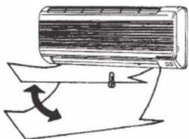
Discharged air
16 Maintenance notice

Warning:
For maintenance or scrap, please contact authorized service centers.
Maintenance by unqualified person may cause dangers.
Feed air conditioner with R32 refrigerant, and maintain the air conditioner in strictly accordance with manufacturer's requirements.
The chapter is mainly focused on special maintenance requirements for appliance with R32 refrigerant. Ask repairer to read after-sales technical service handbook for detailed information.
16.1 Qualification requirements of maintenance personnel
- Special training additional to usual refrigerating equipment repair procedures is required when equipment with flammable refrigerants is affected. In many countries, this training is carried out by national training organisations that are accredited to teach the relevant national competency standards that may be set in legislation. The achieved competence should be documented by a certificate.
- The maintenance and repair of the air conditioner must be conducted according to the method recommended by the manufacturer. If other professionals are needed to help maintain and repair the equipment, it should be conducted under the supervision of individuals who have the qualification to repair AC equipped with flammable refrigerant.
16.2 Inspection of the site
Safety inspection must be taken before maintaining equipment with R32 refrigerant to make sure the risk of fire is minimized. Check whether the place is well ventilated, whether anti-static and fire prevention equipment is perfect.
While maintaining the refrigeration system, observe the following precautions before operating the system.
16.3 Operating procedures
1. General work area:
All maintenance staff and others working in the local area shall be instructed on the nature of work being carried out. Work in confined spaces shall be avoided. The area around the workspace shall be sectioned off. Ensure that the conditions within the area have been made safe by control of flammable material.
16 Maintenance notice
- Checking for presence of refrigerant:
The area shall be checked with an appropriate refrigerant detector prior to and during work, to ensure the technician is aware of potentially toxic or flammable atmospheres. Ensure that the leak detection equipment being used is suitable for use with all applicable refrigerants, i.e. non-sparking, adequately sealed or intrinsically safe.
- Presence of fire extinguisher:
If any hot work is to be conducted on the refrigeration equipment or any associated parts, appropriate fire extinguishing equipment shall be available to hand. Have a dry powder or CO2 fire extinguisher adjacent to the charging area.
- No ignition sources:
No person carrying out work in relation to a refrigeration system which involves exposing any pipe work shall use any sources of ignition in such a manner that it may lead to the risk of fire or explosion. All possible ignition sources, including cigarette smoking, should be kept sufficiently far away from the site of installation, repairing, removing and disposal, during which refrigerant can possibly be released to the surrounding space. Prior to work taking place, the area around the equipment is to be surveyed to make sure that there are no flammable hazards or ignition risks. 'No Smoking' signs shall be displayed.
- Ventilated area (open the door and window):
Ensure that the area is in the open or that it is adequately ventilated before breaking into the system or conducting any hot work. A degree of ventilation shall continue during the period that the work is carried out. The ventilation should safely disperse any released refrigerant and preferably expel it externally into the atmosphere.
- Checks to the refrigeration equipment:
Where electrical components are being changed, they shall be fit for the purpose and to the correct specification. At all times the manufacturer's maintenance and service guidelines shall be followed. If in doubt, consult the manufacturer's technical department for assistance. The following checks shall be applied to installations using flammable refrigerants:
- The charge size is in accordance with the room size within which the refrigerant containing parts are installed.
- The ventilation machinery and outlets are operating adequately and are not obstructed.
- If an indirect refrigerating circuit is being used, the secondary circuit shall be checked for the presence of refrigerant.
- Refrigeration pipe or components are installed in a position where they are unlikely to be exposed to any substance which may corrode refrigerant containing components, unless the components are constructed of materials which are inherently resistant to being corroded or are suitably protected against being so corroded.
16 Maintenance notice
7. Checks to electrical devices:
Repair and maintenance to electrical components shall include initial safety checks and component inspection procedures. If a fault exists that could compromise safety, then no electrical supply shall be connected to the circuit until it is satisfactorily dealt with. If the fault cannot be corrected immediately but it is necessary to continue operation, an adequate temporary solution shall be used. This shall be reported to the owner of the equipment so all parties are advised.
Initial safety checks shall include:
- That capacitors are discharged: this shall be done in a safe manner to avoid possibility of sparking.
- That no live electrical components and wiring are exposed while charging, recovering or purging the system.
- Keep continuity of earthing.
16.4 Inspection of cable
Check the cable for wear, corrosion, overvoltage, vibration and check if there are sharp edges and other adverse effects in the surrounding environment. During the inspection, the impact of aging or the continuous vibration of the compressor and the fan on it should be taken into consideration.
16.5 Leakage check of R32 refrigerant

Note: Check the leakage of the refrigerant in an environment where there is no potential ignition source. No halogen probe (or any other detector that uses an open flame) should be used.
Leak detection method:
For systems with refrigerant R32, electronic leak detection instrument is available to detect and leak detection should not be conducted in environment with refrigerant. Make sure the leak detector will not become a potential source of ignition, and is applicable to the measured refrigerant. Leak detector shall be set for the minimum ignitable fuel concentration (percentage) of the refrigerant. Calibrate and adjust to proper gas concentration (no more than 25%) with the used refrigerant.
The fluid used in leak detection is applicable to most refrigerants. But do not use chloride solvents to prevent the reaction between chlorine and refrigerants and the corrosion of copper pipeline.
If you suspect a leak, then remove all the fire from the scene or put out the fire.
If the location of the leak needs to be welded, then all refrigerants need to be recovered, or, isolate all refrigerants away from the leak site (using cut-off valve). Before and during the welding, use OFN to purify the entire system.
16 Maintenance notice
16.6 Removal and vacuum pumping
- Make sure there is no ignited fire source near the outlet of the vacuum pump and the ventilation is well.
-
Allow the maintenance and other operations of the refrigeration circuit should be carried out according to the general procedure, but the following best operations that the flammability is already taken into consideration are the key. You should follow the following procedures:
-
Remove the refrigerant.
- Decontaminate the pipeline by inert gases.
- Evacuation.
- Decontaminate the pipeline by inert gases again.
-
Cut or weld the pipeline.
-
The refrigerant should be returned to the appropriate storage tank. The system should be blown with oxygen free nitrogen to ensure safety. This process may need to be repeated for several times. This operation shall not be carried out using compressed air or oxygen.
- Through blowing process, the system is charged into the anaerobic nitrogen to reach the working pressure under the vacuum state, then the oxygen free nitrogen is emitted to the atmosphere, and in the end, vacuumize the system. Repeat this process until all refrigerants in the system is cleared. After the final charging of the anaerobic nitrogen, discharge the gas into the atmosphere pressure, and then the system can be welded. This operation is necessary for welding the pipeline.
16.7 Procedures of charging refrigerants
As a supplement to the general procedure, the following requirements need to be added:
- Make sure that there is no contamination among different refrigerants when using a refrigerant charging device. The pipeline for charging refrigerants should be as short as possible to reduce the residual of refrigerants in it.
- Storage tanks should remain vertically up.
- Make sure the grounding solutions are already taken before the refrigeration system is charged with refrigerants.
- After finishing the charging (or when it is not yet finished), label the mark on the system.
- Be careful not to overcharge refrigerants.
16 Maintenance notice
16.8 Scrap and recovery
Scrap:
Before this procedure, the technical personnel shall be thoroughly familiar with the equipment and all its features, and make a recommended practice for refrigerant safe recovery. For recycling the refrigerant, shall analyze the refrigerant and oil samples before operation. Ensure the required power before the test.
- Be familiar with the equipment and operation.
- Disconnect power supply.
-
Before carrying out this process, you have to make sure:
-
If necessary, mechanical equipment operation should facilitate the operation of the refrigerant tank.
- All personal protective equipment is effective and can be used correctly.
- The whole recovery process should be carried out under the guidance of qualified personnel.
-
The recovering of equipment and storage tank should comply with the relevant national standards.
-
If possible, the refrigerating system should be vacuumized.
- If the vacuum state can't be reached, you should extract the refrigerant in each part of the system from many places.
- Before the start of the recovery, you should ensure that the capacity of the storage tank is sufficient.
- Start and operate the recovery equipment according to the manufacturer's instructions.
- Don't fill the tank to its full capacity (the liquid injection volume does not exceed 80% of the tank volume).
- Even the duration is short, it must not exceed the maximum working pressure of the tank.
- After the completion of the tank filling and the end of the operation process, you should make sure that the tanks and equipment should be removed quickly and all closing valves in the equipment are closed.
- The recovered refrigerants are not allowed to be injected into another system before being purified and tested.

Note: The identification should be made after the appliance is scrapped and refrigerants are evacuated. The identification should contain the date and endorsement. Make sure the identification on the appliance can reflect the flammable refrigerants contained in this appliance.
16 Maintenance notice
Recovery:
- The clearance of refrigerants in the system is required when repairing or scrapping the appliance. It is recommended to completely remove the refrigerant.
- Only a special refrigerant tank can be used when loading the refrigerant into the storage tank. Make sure the capacity of the tank is appropriate to the refrigerant injection quantity in the entire system. All tanks intended to be used for the recovery of refrigerants should have a refrigerant identification (i.e. refrigerant recovery tank). Storage tanks should be equipped with pressure relief valves and globe valves and they should be in a good condition. If possible, empty tanks should be evacuated and maintained at room temperature before use.
- The recovery equipment should be kept in a good working condition and equipped with equipment operating instructions for easy access. The equipment should be suitable for the recovery of R32 refrigerants. Besides, there should be a qualified weighting apparatus which can be normally used. The hose should be linked with detachable connection joint of zero leakage rate and be kept in a good condition.
Before using the recovery equipment, check if it is in a good condition and if it gets perfect maintenance. Check if II electrical components are sealed to prevent the leakage of the refrigerant and the fire caused by it. If you have any question, please consult the manufacturer. - The recovered refrigerant shall be loaded in the appropriate storage tanks, attached with a transporting instruction, and returned to the refrigerant manufacturer. Don't mix refrigerant in recovery equipment, especially a storage tank.
- The space loading R32 refrigeration can't be enclosed in the process of transportation. Take anti electrostatic measures if necessary in transportation. In the process of transport, loading and unloading, necessary protective measures must be taken to protect the air conditioner to ensure that the air conditioner is not damaged.
- When removing the compressor or clearing the compressor oil, make sure the compressor is pumped to an appropriate level to ensure that there is no residual R32 refrigerants in the lubricating oil. The vacuum pumping should be carried out before the compressor is returned to the supplier. Ensure the safety when discharging oil from the system.
17 Installation instructions
17.1 F-Gas instruction
This product contains fluorinated greenhouse gases covered by the Kyoto protocol.
The fluorinated greenhouse gases are contained in hermetically sealed equipment.
Installs, services, maintains, repairs, checks for leaks or decommissions equipment and product recycling should be carried out by natural persons that hold relevant certificates.
If the system has a leakage detection system installed, leakage checks should be performed at least every 12 months, make sure system operate properly.
If product must be performed leakage checks, it should specify Inspection cycle, establish and save records of leakage checks.

Note: For hermetically sealed equipment, portable air conditioner, window air conditioner and dehumidifier, if CO2 equivalent of fluorinated greenhouse gases is less than 10 tonnes, it should not perform leakage check.
18 Information servicing
(Required for the units adopt R32/R290 refrigerant only)
1. Checks to the area
Prior to beginning work on systems containing flammable refrigerants, safety checks are necessary to ensure that the risk of ignition is minimised. For repair to the refrigerating system, the following precautions shall be complied with prior to conducting work on the system.
2. Work procedure
Works shall be undertaken under a controlled procedure so as to minimise the risk of a flammable gas or vapour being present while the work is being performed.
3. General work area
All maintenance staff and others working in the local area shall be instructed on the nature of work being carried out. Work in confined spaces shall be avoided. The area around the work space shall be sectioned off. Ensure that the conditions within the area have been made safe by control of flammable material.
4. Checking for presence of refrigerant
The area shall be checked with an appropriate refrigerant detector prior to and during work, to ensure the technician is aware of potentially flammable atmospheres. Ensure that the leak detection equipment being used is suitable for use with flammable refrigerants, i.e. no sparking, adequately sealed or intrinsically safe.
5. Presence of fire extinguisher
If any hot work is to be conducted on the refrigeration equipment or any associated parts, appropriate fire extinguishing equipment shall be available to hand. Have a dry power or CO2 fire extinguisher adjacent to the charging area.
6. No ignition sources
No person carrying out work in relation to a refrigeration system which involves exposing any pipe work that contains or has contained flammable refrigerant shall use any sources of ignition in such a manner that it may lead to the risk of fire or explosion. All possible ignition sources, including cigarette smoking, should be kept sufficiently far away from the site of installation, repairing, removing and disposal, during which flammable refrigerant can possibly be released to the surrounding space. Prior to work taking place, the area around the equipment is to be surveyed to make sure that there are no flammable hazards or ignition risks. “NO SMOKING” signs shall be displayed.
7. Ventilated area
Ensure that the area is in the open or that it is adequately ventilated before breaking into the system or conducting any hot work. A degree of ventilation shall continue during the period that the work is carried out. The ventilation should safely disperse any released refrigerant and preferably expel it externally into the atmosphere.
18 Information servicing
8. Checks to the refrigeration equipment
Where electrical components are being changed, they shall be fit for the purpose and to the correct specification. At all times the manufacturer's maintenance and service guidelines shall be followed.
If in doubt consult the manufacturer's technical department for assistance. The following checks shall be applied to installations using flammable refrigerants:
- the charge size is in accordance with the room size within which the refrigerant containing parts are installed;
- the ventilation machinery and outlets are operating adequately and are not obstructed;
- if an indirect refrigerating circuit is being used, the secondary circuits shall be checked for the presence of refrigerant; marking to the equipment continues to be visible and legible.
• marking and signs that are illegible shall be corrected; - refrigeration pipe or components are installed in a position where they are unlikely to be exposed to any substance which may corrode refrigerant containing components, unless the components are constructed of materials which are inherently resistant to being corroded or are suitably protected against being so corroded.
9. Checks to electrical devices
Repair and maintenance to electrical components shall include initial safety checks and component inspection procedures. If a fault exists that could compromise safety, then no electrical supply shall be connected to the circuit until it is satisfactorily dealt with. If the fault cannot be corrected immediately but it is necessary to continue operation, and adequate temporary solution shall be used. This shall be reported to the owner of the equipment so all parties are advised.
Initial safety checks shall include:
- that capacitors are discharged: this shall be done in a safe manner to avoid possibility of sparking
- that there no live electrical components and wiring are exposed while charging, recovering or purging the system;
• that there is continuity of earth bonding.
10. Repairs to sealed components
10.1. During repairs to sealed components, all electrical supplies shall be disconnected from the equipment being worked upon prior to any removal of sealed covers, etc. If it is absolutely necessary to have an electrical supply to equipment during servicing, then a permanently operating form of leak detection shall be located at the most critical point to warn of a potentially hazardous situation.
10.2. Particular attention shall be paid to the following to ensure that by working on electrical components, the casing is not altered in such a way that the level of protection is affected. This shall include damage to cables, excessive number of connections, terminals not made to original specification, damage to seals, incorrect fitting of glands, etc.
18 Information servicing
- Ensure that apparatus is mounted securely.
- Ensure that seals or sealing materials have not degraded such that they no longer serve the purpose of preventing the ingress of flammable atmospheres. Replacement parts shall be in accordance with the manufacturer's specifications.

Note: The use of silicon sealant may inhibit the effectiveness of some types of leak detection equipment. Intrinsically safe components do not have to be isolated prior to working on them.
11. Repair to intrinsically safe components
Do not apply any permanent inductive or capacitance loads to the circuit without ensuring that this will not exceed the permissible voltage and current permitted for the equipment in use. Intrinsically safe components are the only types that can be worked on while live in the presence of a flammable atmosphere. The test apparatus shall be at the correct rating. Replace components only with parts specified by the manufacturer. Other parts may result in the ignition of refrigerant in the atmosphere from a leak.
12. Cabling
Check that cabling will not be subject to wear, corrosion, excessive pressure, vibration, sharp edges or any other adverse environmental effects. The check shall also take into account the effects of aging or continual vibration from sources such as compressors or fans.
13. Detection of flammable refrigerants
Under no circumstances shall potential sources of ignition be used in the searching for or detection of refrigerant leaks. A halide torch (or any other detector using a naked flame) shall not be used.
14. Leak detection methods
The following leak detection methods are deemed acceptable for systems containing flammable refrigerants. Electronic leak detectors shall be used to detect flammable refrigerants, but the sensitivity may not be adequate, or may need re-calibration.(Detection equipment shall be calibrated in a refrigerant-free area.) Ensure that the detector is not a potential source of ignition and is suitable for the refrigerant. Leak detection equipment shall be set at a percentage of the LFL of the refrigerant and shall be calibrated to the refrigerant employed and the appropriate percentage of gas (25% maximum) is confirmed. Leak detection fluids are suitable for use with most refrigerants but the use of detergents containing chlorine shall be avoided as the chlorine may react with the refrigerant and corrode the copper pipe-work.
If a leak is suspected, all naked flames shall be removed or extinguished. If a leakage of refrigerant is found which requires brazing, all of the refrigerant shall be recovered from the system, or isolated (by means of shut off valves) in a part of the system remote from the leak. Oxygen free nitrogen (OFN) shall then be purged through the system both before and during the brazing process.
18 Information servicing
15. Removal and evacuation
When breaking into the refrigerant circuit to make repairs of for any other purpose conventional procedures shall be used. However, it is important that best practice is followed since flammability is a consideration. The following procedure shall be adhered to:
- remove refrigerant;
• purge the circuit with inert gas; - evacuate;
• purge again with inert gas; - open the circuit by cutting or brazing.
The refrigerant charge shall be recovered into the correct recovery cylinders. The system shall be flushed with OFN to render the unit safe. This process may need to be repeated several times. Compressed air or oxygen shall not be used for this task.
Flushing shall be achieved by breaking the vacuum in the system with OFN and continuing to fill until the working pressure is achieved, then venting to atmosphere, and finally pulling down to a vacuum. This process shall be repeated until no refrigerant is within the system.
When the final OFN charge is used, the system shall be vented down to atmospheric pressure to enable work to take place. This operation is absolutely vital if brazing operations on the pipe-work are to take place.
Ensure that the outlet for the vacuum pump is not closed to any ignition sources and there is ventilation available.
16. Charging procedures
In addition to conventional charging procedures, the following requirements shall be followed:
- Ensure that contamination of different refrigerants does not occur when using charging equipment. Hoses or lines shall be as short as possible to minimize the amount of refrigerant contained in them.
• Cylinders shall be kept upright. - Ensure that the refrigeration system is earthed prior to charging the system with refrigerant.
- Label the system when charging is complete (if not already).
• Extreme care shall be taken not to overfill the refrigeration system. - Prior to recharging the system it shall be pressure tested with OFN. The system shall be leak tested on completion of charging but prior to commissioning. A follow up leak test shall be carried out prior to leaving the site.
18 Information servicing
17. Decommissioning
Before carrying out this procedure, it is essential that the technician is completely familiar with the equipment and all its detail. It is recommended good practice that all refrigerants are recovered safely. Prior to the task being carried out, an oil and refrigerant sample shall be taken.
In case analysis is required prior to re-use of reclaimed refrigerant. It is essential that electrical power is available before the task is commenced.
a) Become familiar with the equipment and its operation.
b) Isolate system electrically
c) Before attempting the procedure ensure that:
- mechanical handling equipment is available, if required, for handling refrigerant cylinders;
• all personal protective equipment is available and being used correctly; - the recovery process is supervised at all times by a competent person;
• recovery equipment and cylinders conform to the appropriate standards.
d) Pump down refrigerant system, if possible.
e) If a vacuum is not possible, make a manifold so that refrigerant can be removed from various parts of the system.
f) Make sure that cylinder is situated on the scales before recovery takes place.
g) Start the recovery machine and operate in accordance with manufacturer's instructions.
h) Do not overfill cylinders. (No more than 80% volume liquid charge).
i) Do not exceed the maximum working pressure of the cylinder, even temporarily.
j) When the cylinders have been filled correctly and the process completed, make sure that the cylinders and the equipment are removed from site promptly and all isolation valves on the equipment are closed off.
k) Recovered refrigerant shall not be charged into another refrigeration system unless it has been cleaned and checked.
18. Labelling
Equipment shall be labelled stating that it has been de-commissioned and emptied of refrigerant. The label shall be dated and signed. Ensure that there are labels on the equipment stating the equipment contains flammable refrigerant.
19. Recovery
- When removing refrigerant from a system, either for service or decommissioning, it is recommended good practice that all refrigerants are removed safely.
18 Information servicing
- When transferring refrigerant into cylinders, ensure that only appropriate refrigerant recovery cylinders are employed. Ensure that the correct numbers of cylinders for holding the total system charge are available. All cylinders to be used are designated for the recovered refrigerant and labelled for that refrigerant (i.e. special cylinders for the recovery of refrigerant). Cylinders shall be complete with pressure relief valve and associated shut-off valves in good working order.
• Empty recovery cylinders are evacuated and, if possible, cooled before recovery occurs. - The recovery equipment shall be in good working order with a set of instructions concerning the equipment that is at hand and shall be suitable for the recovery of flammable refrigerants. In addition, a set of calibrated weighing scales shall be available and in good working order.
- Hoses shall be complete with leak-free disconnect couplings and in good condition. Before using the recovery machine, check that it is in satisfactory working order, has been properly maintained and that any associated electrical components are sealed to prevent ignition in the event of a refrigerant release. Consult manufacturer if in doubt.
- The recovered refrigerant shall be returned to the refrigerant supplier in the correct recovery cylinder, and the relevant Waste Transfer Note arranged. Do not mix refrigerants in recovery units and especially not in cylinders.
- If compressors or compressor oils are to be removed, ensure that they have been evacuated to an acceptable level to make certain that flammable refrigerant does not remain within the lubricant. The evacuation process shall be carried out prior to returning the compressor to the suppliers. Only electric heating to the compressor body shall be employed to accelerate this process. When oil is drained from a system, it shall be carried out safely.
20. Transportation, marking and storage for units
- Transport of equipment containing flammable refrigerants
Compliance with the transport regulations
- Marking of equipment using signs
Compliance with local regulations
- Disposal of equipment using flammable refrigerants
Compliance with national regulations
- Storage of equipment/appliances
The storage of equipment should be in accordance with the manufacturer's instructions.
- Storage of packed (unsold) equipment
Storage package protection should be constructed such that mechanical damage to the equipment inside the package will not cause a leak of the refrigerant charge.
The maximum number of pieces of equipment permitted to be stored together will be determined by local regulations.
19 Specifications
| Beko Model Name BEMPE 090 BEMPE 120 | ||
| Cooling Capacity - (Btu/h) 8803 11942 | ||
| Cooling Capacity - (W) 2580 3500 | ||
| Heating Capacity - (Btu/h) 9215 11942 | ||
| Heating Capacity - (W) 2700 3500 | ||
| Air flow volume - (m3/h) 600/480/370 600/480/370 | ||
| Sound Pressure Level - (dBA) 40/38/34 42/40/36 | ||
| Sound Power Level - (dBA) 54 54 | ||
| Power Supply - (Ph / V~ / Hz) 220~240V, 50Hz | 220~240V, 50Hz | |
| Power Supply Part | Outdoor | Outdoor |
| Net Dimensions (WxHxD) - mm | 750×200×285 | 750×200×285 |
| Net Weigh - kg | 7.5 | 8 |
| Packing Dimensions (WxHxD) - mm | 820×277×347 | 820×277×347 |
| Gross Weight - kg | 9 | 10 |
| Beko Model Name | BEMPF 181 | BEMPF 271 |
| Product Mix | (BEMPE 090*1pc + BEMPE 120*1pc) | (BEMPE 090*2pcs + BEMPE 120*1pc) |
| Type | Multi ODU | Multi ODU |
| Climate Class | T1 | T1 |
| Refrigerant | R32 | R32 |
| Total Refrigerant Amount - g | 1100 | 1200 |
| Cooling Operation Ambient Temperature Range - °C | -10~52 | -10~52 |
| Heating Operation Ambient Temperature Range - °C | -15~24 | -15~24 |
| Maximum drive Indoor unit NO. - Unit | 2 | 3 |
| Pdesign - Cooling Capacity - (Btu/h) | 18084 (Pdesign C) | 26955 (Pdesign C) |
| Pdesign - Cooling Capacity - (W) | 5300 (Pdesign C) | 7900 (Pdesign C) |
| Pdesign - Heating Capacity - (Btu/h) | 15695 (Pdesign H Average) | 22860 (Pdesign H Average) |
| Pdesign - Heating Capacity - (W) | 4600 (Pdeisgn H Average) | 6700 (Pdeisgn H Average) |
| Adjustable Compressor Frequency Range (Hz) [Cooling] | 30~80 | 25~80 |
| Adjustable Cooling Capacity Range - (Btu/h) | 6824-19892 | 7848~29650 |
19 Specifications
| Adjustable Cooling Capacity Range - W | 2000~5830 2300~8690 | |
| Adjustable Compressor Frequency Range (Hz) [Heating] | 30~100 25~100 | |
| Adjustable Heating Capacity Range - Btu/h | 7541~21071 8359~30776 | |
| Adjustable Heating Capacity Range - (W) | 2210~6160 2450~9020 | |
| SEER/AEER/Weight EER (W/W) 6.10 | (SEER, EU) 6.10 (SEER, EU) | |
| SCOP/ACOP/Weight EER (W/W) 4.0 | SCOP Average, EU) 4.0 (SCOP Average, EU) | |
| SEER/AEER/SASO/TICK etc. A++ (EU) | A++ (EU) | |
| SCOP/ACOP/SASO/TICK etc. A+ (EU) | Average Season) A+ (EU, Average Season) | |
| Pdesign C (kw) 5.3 7.9 | ||
| Pdesign H (kw) 4.6 6.7 | ||
| Annual Energy Consumption-Cooling (kwh) | 304 453 | |
| Annual Energy Consumption-Heating (kwh) | 1610 | 2345 |
| The declared capacity for calculation of SCOP at reference design condition (kW) | 4.3 6.6 | |
| The back up heating capacity assumed for calculation of SCOP at reference design condition (kW) | 0.3 0.1 | |
| Moisture removal - (L/H.r) | / | / |
| Sound Pressure Level - (dBA) | 55 | 58 |
| Sound Power Level - (dBA) | 62 | 65 |
| Power Supply - (Ph / V~ / Hz) | 220~240V, 50Hz | 220~240V, 50Hz |
| Power Supply Part | Outdoor unit | Outdoor unit |
| Rated Power Input - Cooling - (W) | 1750 | 2460 |
| Rated Power Input - Heating -(W) | 1540 | 2270 |
| Air flow volume - (m3/h) | 2300 | 3100 |
| Net Dimensions (WxHxD) - mm | 800×545×315 | 834×655×328 |
| Net Weigh - (kg) | 36 | 46 |
| Packing Dimensions (WxHxD) - mm | 920×620×400 945×725×435 | |
| Gross Weight - (kg) | 39 | 49 |
| Importer in PolandImporter W PolsceBeko S.A.ul. Puławska 366 02-819Warszawawww.beko.pl | Importer in Czech RepublicDovozce do České republikyBEKO S.A., organizačnísložka Bucharova 1423/6, Praha 13 - Nové Butovice,158 00www.bekocr.cz | Importer in SlovakiaDovozca na SlovenskoBEKO Slovakia s.r.o. Suchémýto 1 811 03 Bratislavawww.bekosk.sk | Importer in EstoniaImportija EestiBeko S.A. TănavPuławska 366 02-819 Varssavi (Poola) | |||
| Importer in GermanyBeko Deutschland GmbHThomas-Edison-Platz 3 63263Neu-Isenburg | Importer in UKBEKO Plc, Beko House, 1 GreenhillCrescent, Watford, Herts,WD18 8QU | KSA ImporterAL BABTAIN TRADING CO. P.O.Box# 181, Riyadh 11411-KSA+966-11-4744788 | Importer in FranceBEKO France / Immeuble Stadium 266,Avenue du Président Wilson 93218La Plaine Saint-Denis Cedex | |||
| Importer in SpainBEKO ELECTRONICESPANA S.L.C/ Provenza388 1° Piso/08025 Barcelona | Importer for MaltaETV LTD119/120Archbishop StreetVALLETTA MALTA | Importer in LatviaImportētāja LatvijāBeko S.A.Ielas Puławska 366 02-819Varšava (Polija) | Importer in LithuaniaImportuotojas LietuvojeBeko S.A.Gatvė Puławska 366 02-819Varšuva (Lenkija) | |||
| Importer in AustriaELEKTRA BREGENZ AGPFARRGASSE 77 VIENNA postcode 1230 | Importer in SwitzerlandGrundig Nordic ABIsafjordsgatan 39B16440Kista SWEDEN | Importer in HungaryHauser Magyarorszagimited Baross utca89 PC: 2040Budaörs/Hungary | Importer in SloveniaBIG BANG, D.O.O.Šmartinska cesta 152PC: 1000Ljubljana/Slovenia | Importer in ItalyBEKO ITALY SRLViale Del Ghisallo,20/I-20151 Milano (MI) | ||
| Importer in RomaniaARCTIC S.A.Str. 13 Decembrie, nr.210 Găeşti,135200, Româniawww.arctic.ro | Importer in BeneluxSchaliënhoevedreefB -2800Mechelen - Belgium | Importer in GreecePAR. SEITANIDIS S.A.Polistilo, P.O. Box:1402Kavala, 64003 | Importer in BulgariaVideolux LTD/PO Box2109/2109 Sofia | Importer in CroatiaE PLUS dooZA Unutarnju/GOSPODARSKA 16c/10225 GORNJI STUPNIK/ZAGREP | ||
| Importer in Russia Импортер на территории РФ: ООО «БЕКО», 601021, Россия, Владимирская область,Киржачский район, деревня Федоровское, улица Сельская, 49Бесплатная линия сервисного обслуживания и информационной поддержки по установке и эксплуатации(только для звонков по России) 8-800-200-23-56Изготовитель: Arcelik A.Ş. Турция, Karaagac caddesi No: 2-6 Istanbul 34445 Sutluce, Istanbul | ||||||
| Виробник: «Arçelik A.Ş» Karaağaç Caddesi No: 2-6, Sütlüce, 34445 İstanbul, Turkey, «Arçelik A.Ş», м. Стамбул,Сютлюдже, вул. Караагач No 2-6, 34445, ТуреччинаИмпортер на території України:ТОВ «Беко Україна», адреса: 03150, м. Київ, вул. Антоновича, буд. 72, тел/факс.: 0-800-500-4-3-2 Термін служби 3 роки | ||||||
| Manufactured by Arcelik A.S. Karaagac Cd. No: 2-6 34445 Sutluce, Beyoglu, Istanbul, Turkey 19/10 Rev: 01 | ||||||
3 Funzionamento
3.1 Telecomando
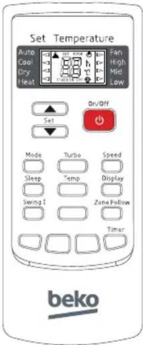

Nota:

Nota:
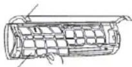
Aria di scarico
16.3 Procedure operative
3 Funcionamiento

Nota:

Nota:
Panel frontal Panel frontal
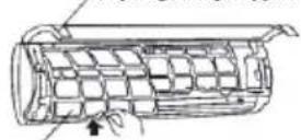
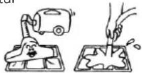
Aire descargado
- FREE MATCH SPLIT TYPE AIR CONDITIONER
- PLEASE READ THIS USER MANUAL FIRST
- MEANINGS OF THE SYMBOLS
- CONTENTS
- SAFETY INSTRUCTIONS
- WEEE WARNING
- OPERATION
- MANUAL OPERATION
- NOTICES
- CARE AND MAINTENANCE
- TROUBLESHOOTING
- INSTALLATION GUIDE
- NOTICES OF INSTALLATION
- SELECTION OF THE INSTALLING POSITION
- INSTALLATION OF THE INDOOR UNIT
- INSTALLATION OF THE OUTDOOR UNIT
- PIPE CONNECTION
- WARNING
- NOTE ABOUT FLUORINATED GASSES
- REMOTE CONTROLLER
- NOTE
- SETTING THE "ON" TIMER TIME
- SETTING THE "OFF" TIMER TIME
- USAGE
- AUTOMATIC OPERATION MODE
- COOLING/HEATING OPERATION MODE (COLD WIND TYPE HAS NO HEATING FUNCTION)
- FAN OPERATION MODE
- DRYING OPERATION MODE
- FIX BATTERIES
- ATTENTION
- ADJUSTING AIR FLOW DIRECTION
- ADJUSTING HORIZONTAL AIR FLOW MANUALLY
- ADJUSTING VERTICAL AIR FLOW DIRECTION (UP-DOWN)
- CHECKING BEFORE OPERATION
- SAFETY TIPS
- NOTICES FOR R32 MODELS
- CLEANING
- CLEANING THE INDOOR UNIT
- CLEANING AIR FILTER
- MAINTENANCE
- FAULT CODE
- GUIDE FOR CUSTOMER
- UNPACKING INSPECTION
- SAFETY PRINCIPLES FOR INSTALLING AIR CONDITIONER
- REQUIREMENTS FOR INSTALLATION POSITION
- INSTALLATION ENVIRONMENT INSPECTION
- INDOOR UNIT
- OUTDOOR UNIT
- WALL-MOUNTED INSTALLATION
- WALL-MOUNTED AIR CONDITIONER UNIT
- CHECK THE WATER EXHAUSTING
- THE FORM OF PIPE
- EXPELLING THE AIR IN THE PIPES AND THE INDOOR UNIT
- ELECTRICAL CONNECTION
- TEST RUNNING
- THE CONNECTION OF POWER SOURCE
- PERFORMANCE EVALUATION
- MAINTENANCE NOTICE
- QUALIFICATION REQUIREMENTS OF MAINTENANCE PERSONNEL
- INSPECTION OF THE SITE
- OPERATING PROCEDURES
- GENERAL WORK AREA
- CHECKS TO ELECTRICAL DEVICES
- INSPECTION OF CABLE
- LEAKAGE CHECK OF R32 REFRIGERANT
- REMOVAL AND VACUUM PUMPING
- PROCEDURES OF CHARGING REFRIGERANTS
- SCRAP AND RECOVERY
- SCRAP
- RECOVERY
- INSTALLATION INSTRUCTIONS
- F-GAS INSTRUCTION
- INFORMATION SERVICING
- (REQUIRED FOR THE UNITS ADOPT R32/R290 REFRIGERANT ONLY)
- CHECKS TO THE AREA
- WORK PROCEDURE
- CHECKING FOR PRESENCE OF REFRIGERANT
- PRESENCE OF FIRE EXTINGUISHER
- NO IGNITION SOURCES
- VENTILATED AREA
- CHECKS TO THE REFRIGERATION EQUIPMENT
- INITIAL SAFETY CHECKS SHALL INCLUDE
- REPAIRS TO SEALED COMPONENTS
- REPAIR TO INTRINSICALLY SAFE COMPONENTS
- CABLING
- DETECTION OF FLAMMABLE REFRIGERANTS
- LEAK DETECTION METHODS
- REMOVAL AND EVACUATION
- CHARGING PROCEDURES
- DECOMMISSIONING
- LABELLING
- TRANSPORTATION, MARKING AND STORAGE FOR UNITS
- FUNZIONAMENTO
- TELECOMANDO
- NOTA
- PROCEDURE OPERATIVE
- FUNCIONAMIENTO
Brand : BEKO
Model : BEMPE 090
Category : Air conditioner