
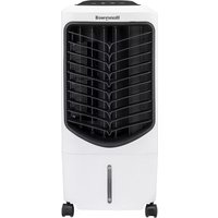
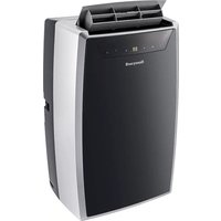
KALTECCOOL PW60A-B - Portable air conditioner HONEYWELL - Free user manual and instructions
Find the device manual for free KALTECCOOL PW60A-B HONEYWELL in PDF.
| Product type | Water softener |
| Available models | PW60-A (single-family houses) / PW60-B (two-family houses) |
| Supply voltage | 230 V / 50 Hz (external transformer) |
| Low protection voltage | 24 V |
| Power consumption | 2 W (during treatment) |
| Protection rating | IP 22 |
| Water connection | 1" AG |
| Effluent connection | Olive fitting 1/2" |
| Nominal pressure | PN 10 |
| Operating pressure | 2 to 6 bar |
| Nominal flow rate (wellness mode) | 2.8 m³/h with Δp = 0.8 bar |
| Permissible water temperature | 5 to 30 °C |
| Ambient temperature | 2 to 40 °C |
| Resin volume | 4 L (PW60-A) / 10 L (PW60-B) |
| Salt consumption per regeneration | 790 g (PW60-A) / 1980 g (PW60-B) |
| Effluent volume per regeneration | 30 L (PW60-A) / 59 L (PW60-B) |
| Delivery contents | Tank, control head, resin bottle, external transformer, flexible hoses |
| Functions | Automatic regeneration (flow or time), holiday mode, flow and reserve indicator |
| Maintenance | Annual by professional (WS60-A kit) |
| Optional accessories | Filter FK74C, pressure regulator, separator R295/BA295, connection piece DA74C, recharge bag VC51-A |
Frequently Asked Questions - KALTECCOOL PW60A-B HONEYWELL
User questions about KALTECCOOL PW60A-B HONEYWELL
0 question about this device. Answer the ones you know or ask your own.
Ask a new question about this device
Download the instructions for your Portable air conditioner in PDF format for free! Find your manual KALTECCOOL PW60A-B - HONEYWELL and take your electronic device back in hand. On this page are published all the documents necessary for the use of your device. KALTECCOOL PW60A-B by HONEYWELL.
USER MANUAL KALTECCOOL PW60A-B HONEYWELL
natural_image
Illustration of a Honeywell industrial gas pump unit with control panel and digital display (no text or symbols on main body)CE
Wasserbehandlung
Water Treatment
Traitement de l'eau
Waterbehandeling
Honeywell
CE
KONFORMITÄTSERKLÄRUNG DECLARATION OF CONFORMITY DECLARATION DE CONFORMITE
Gemäß / In Accordance with / Conforme à: 89/336/ECC, 73/23/ECC
Titel
Title
Titre
Low Voltage Directive
Electromagnetic Compatibility – Generic Emission Standard, Part 1: Commercial, Residential, Industrial
Electromagnetic Compatibility – Generic Immunity Standard, Part 1: Commercial, Residential, Light Industrial
EC guidelines & harmonized norms, EC-project norms
The monitoring is performed by:
Uwe Pfeiffer - Engineering Leader
(Name, Funktion/ Name, Function/ Nom, fonction)
Mosbach, 11.12.2005
Declaration of conformity in accordance with DIN EN 45014 and ISO/IEC Guide 22
natural_image
Mechanical valve assembly diagram showing internal components and a shaft (no text or labels)natural_image
Mechanical valve assembly diagram showing internal components and a handle (no text or labels)natural_image
Technical illustration of a pressure regulator valve with three fittings and a central gauge (no text or symbols)D06F

DA74C
AS60-Y
natural_image
Cross-sectional illustration of a mechanical pressure relief device (no text or symbols visible)FKN74C

natural_image
Technical illustration of a pressure regulator with valve and gauge (no text or symbols)R295
natural_image
Technical illustration of a mechanical valve assembly (no text or symbols visible)BA295
15. Zubehör
D06F Druckminderer
- Follow the installation instructions.
- Use the appliance
• according to its intended use -
in good condition
• with due regard to safety and risk of danger. -
Note that the appliance is exclusively for use in the applications detailed in these installation instructions. Any other use will not be considered to comply with requirements and would invalidate the warranty.
-
Please take note that any assembly, commissioning, servicing and adjustment work may only be carried out by authorized persons.
-
Immediately rectify any malfunctions which may influence safety.
2. Functional description
Hard or medium-hard drinking water contains large amounts of lime, which can deposit in pipes, fittings and devices and result in irreparable damages.
The water treatment device is based on the simple exchange of salts. Calcium ions are replaced by other ion pairs.
3. Application
Water temperature 5 - 30 °C
Ambient temperature 2 - 40 °C
Operating pressure 2 - 6 bar
4. Technical data
Nominal pressure PN 10
Flow rate at p=0,8 bar 2,8 m ^3 /h (wellness mode)
Supply voltage (ext. transfor-230 V / 50 Hz mer)
Protective extra low voltage 24 V
Power consumption 2 W (during conditioning)
Safety class IP 22
Connection size 1" AG
Drain connection 1/2" hose nozzle
| Model | Resin volume (l) | Waste water, regeneration water (l/regeneration) | Salt/magnesium consumption (g/regeneration) |
| PW60-A | 4 | 30 | 790 |
| PW60-B | 10 | 59 | 1980 |
5. Scope of delivery
KaltecCool consists of:
• Cabinet in modern, space-saving design
- Flow controlled electronic regeneration automatics with time priority control, holiday control.
• Status indicator and control panel
• Control valve element
- Flask with monodisperse ion exchanger resin
- External transformer; the device is only fed with a protective low voltage of 24 V
- Two armoured hoses with matching piece to DA74C
6. Options
PW60-A = Use in detached houses
PW60-B = Use in two to three family houses
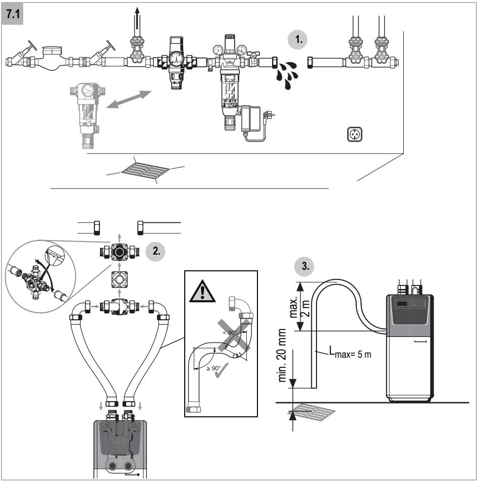
7. Assembly
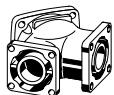
- In order to protect the device against foreign particles, it must only be installed with an upstream fine filter (recommended by Honeywell FK74C)
- In case of high inlet pressure (> 6 bar) a pressure reducer must be installed in upstream
- A drain connection within five meters distance or two meters height must be available. The drain hose must not be kinked in any way as this will lead to an overflow of the device.
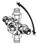
- When using DA74C, connection in horizontal or vertical pipelines is possible
- All works should only be carried out by a qualified person, in compliance with local water regulations
- The installation location should be protected against frost and extreme heat
- The device is fitted with a check valve and therefore must not be fitted between a water heater and the pressure relief safety valve
- After the installation one must set time and water hardness on the device and trigger a manual regeneration process
- The device must be secured according to the corresponding national implementation of the standard EN 1717. For installation in Germany the device must be secured with a pipe separator (type Honeywell R295) or a system separator (type Honeywell BA295) according to DIN EN 1717 or DIN 1988/T4. With low inlet pressure (< 3 bar) the use of the pipe separator is recommended.
7.1 Assembly instructions

Caution!
In order to avoid irreversible damages to the water conditioning device, all welding and soldering work in the immediate vicinity has to be completed prior to assembly!
- Thoroughly flush pipework
- Install the water conditioning device.
o Connect the water conditioning device
o Use of connecting fitting DA74C
o Note flow direction
- Connect the waste water hose to the hose socket on the back of the control head

Caution!
Make sure the seal is fitted properly!
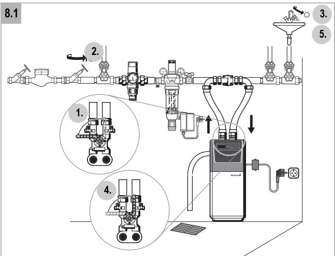
8. Commissioning

Caution!
Commissioning has to take place in the following order!
8.1 Flush and Deaerate
- Set the water conditioning device to "Bypass".
- Open the main water supply.
- Open the nearest cold water tap and allow the water to run. Impurities and soldering remains are flushed out of the pipework.
- Set the water conditioning device to "Service".
- Deaerate the water conditioning device, flush for approx. 10 minutes, e.g. by opening a tap
- Close the cold water tap.

Noise development can occur during regeneration due to incomplete deaerating. However, this will disappear after 2-3 regenerations!
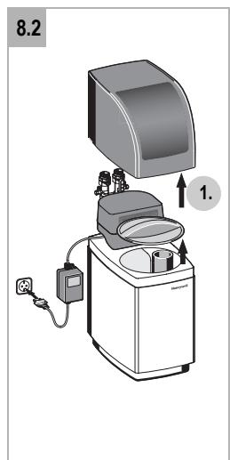
8.2 Filling the cabinet
- Remove covering cap and salt lid. The brine tube remains closed.
- Fill the cabinet up to approx. 3 l with water and then fill up with 1 bag of magnesium salt

The "Min-Max" marks refer to the salt filling level.
- Wait approx. 15 minutes, until brine has developed
8.3 Time Setting
- Connect the power supply, the display starts flashing

Caution!
The socket outlet must have continuous voltage, it must not be linked with light switches or similar.
- Set the time via the ▲ and ▼ buttons.
8.4 Determining Water Hardness
-
Determine the water hardness on the inlet side (using the enclosed hardness measuring instruments) o Sample water from the sample tap on the connecting set, or set the water conditioning device to "bypass" position and extract a water sample from the first tapping point
-
Determine the water hardness via a hardness measuring instrument.
-
Set the water conditioning device to "Service".
-
Set water hardness on the device, see 10.3
8.5 Manual Regeneration
- Press the button ☐. Manual regeneration starts immediately.

Flushing takes place via the drain tube during regeneration!
9. Operation
9.1 Control Buttons, Display and Indicators
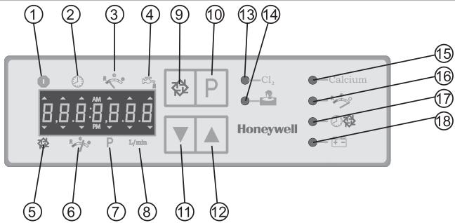
Display
1 Operation indicator
• Arrow lights up = valve is in operation
• Arrow flashes = regeneration at night*
2 Time
3 Reserve indicator*
4 Flow display
• Arrow flashes = water draw-off
5 Regeneration indicator
• Arrow flashes = regeneration phase is running
6 Remaining volume indicator
7 Programming Mode
• Arrow lights up = Programming Mode active
8 External*
*Display deactivated
Function keys
9 Start the manual regeneration
10 Programming
11 Adjusting displayed value downwards
12 Adjusting displayed value upwards
Indicator lamps
13 Chlorine generation (function not active)
14 Holiday Mode active
15 Setting the water hardness
16 Setting the capacity of the system*
17 Setting the time for regeneration at night*
18 Power indicator
9.2 Display during Operation
During operation the time alternates with the remaining volume on the display. During the usage of water the remaining volume (only treated part) decreases to zero. Afterwards – every 4 days, however, the latest – a manual regeneration is actuated.
Time

Residual volume (litre)

9.3 Display during Regeneration
During regeneration the active regeneration phase is displayed. In addition to the phase number the remaining time of the active phase is also displayed. After all 6 phases have been completed, the water conditioning device returns to normal operation.
The total time is between 45 and 60 minutes.
Time
Example: Regeneration has reached phase no. 3, the remaining time of this phase is 9,3 minutes.

Phase
1 Quick flushing, formation of brine
2 Active time
3 Slow flushing
4 Quick flushing
5 Backwashing
6 Refilling

All 6 regeneration phases run in succession.
With PW 60-A phase 6 is not separately indicated.
9.4 Holiday Mode
Device can be set into a Holiday Mode, i. e.:
- If no water has been drawn off 4 days after the last regeneration a new regeneration is started. Afterwards the device rests in holiday position.
- As soon as water is drawn off again the device stops the regeneration.
9.5 Guidelines for operation

Regular inspection of magnesium level - approx. every 4 weeks
The system needs to be filled up if the magnesium level has dropped below the "Min"-mark. Use a complete bag of VC51-A to fill up.
10. Maintenance
10.1 Settings
10.2 Time Setting
In order to set the time press arrow keys ▲ and ▼.
10.3 Setting the water hardness
In order to set the water hardness press the Ⓗ key for 5 seconds, set hardness via arrow keys ▲ and ▼ and store entry by pressing the Ⓞ key again.
10.4 Changing and/or omitting phases
A manual regeneration can be actuated at any time, even if the remaining volume has not reached zero yet.
- Briefly press the ☐ key.
10.5 Changing and/or omitting phases
In order to quickly jump to the next phase during the regeneration press the ☐ key.
11. Working method during power failure
In case the power supply is interrupted for a longer period of time it is recommended to set the device to bypass position for the time of power failure.
12. Maintenance
In accordance with the directive DIN 1988 the device must be maintained regularly, normally at least once a year. Honeywell provides suitable Maintenance-Sets.
The maintenance must be carried out by expert personnel (fitter, service technician).
13. Further settings
For magnesium operation you can choose between wellness mode (13.1) and sanitation mode (13.2). Apart from this, you can use any desired setting between these two modes, in order to achieve a treatment result that matches your requirements.
13.1 Wellness Mode
This operating mode stands out due to favorable consumption of magnesium and water.

Please note that for Wellness and Cleaning Modes the water hardness remains unaltered and therefore washing machines and dishwashers should be operated as before, that is with the same quantities of washing, rinsing and softening materials as before.
Even in Wellness Mode some removal of deposits may occur and in the initial period this may lead to some detached particles of scale appearing on the outlets.
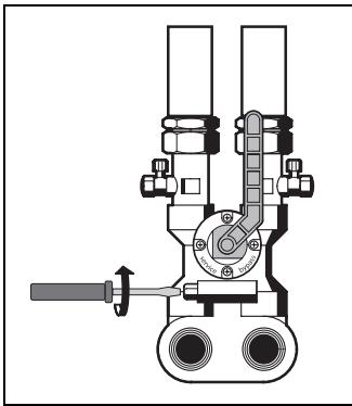
- In order to activate wellness mode turn the setscrew first completely in anti-clockwise, then back it out in clockwise direction, until the hand points to the red mark.
o Do not turn in too far!
natural_image
Mechanical valve assembly diagram showing internal components and a handle (no text or labels)13.2 Cleaning Mode
This operating mode is characterized by an optimal conditioning result and cleans old systems of existing scale deposits.

- During Cleaning Mode scale deposits which have become detached from the pipework walls may appear at the outlets.
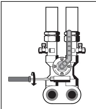
- In order to activate the sanitation mode turn the setscrew completely in anti-clockwise.
o Do not turn in too far
natural_image
Technical line drawing of a mechanical valve assembly (no text or symbols)- Troubleshooting
| Problem | Cause | Remedy |
| No water supply to the device | Shut-off device in the bypass is not open or only partially open | Open shut off valve fully |
| Pipework of the drinking water supply is calcified or blocked | Clean or replace the pipework | |
| Device does not regenerate | Flow meter is defective | Check and, if necessary, replace the flow meter (CS*) |
| Incorrect settings at the control valve | Check the control valve settings | |
| Water meter is contaminated or defective | Clean and, if necessary, replace water meter (CS*) | |
| Internal electric cabling is defective | Check internal electric cabling (CS*) | |
| Call Technical Customer Service | ||
| Wrong connection of connecting hoses | Connect the flexible connection lines correctly | |
| Device does not regenerate, "Holiday Mode" LED is permanently on (> 10 minutes) despite tapping of water | No signal from flow meter | Check and, if necessary, replace the flow meter (CS*) |
| Nothing is displayed | Power supply has been interrupted | Check power supply (mains plug, fuse) |
| Control head is defective | Call Technical Customer Service | |
| Incorrect time is displayed | Power failure occurred | Set the time |
| Tank overflows | Internal pipework is contaminated or leaking | Check pipework (CS*) |
| Float valve is defective | Check float valve (CS*) | |
| Insufficient function | Device not deaerated | Deaerate device |
| Device is in "Bypass" position | Set device to "Service" position | |
| Incorrect settings at the control valve | Check the control valve settings | |
| Storage tank is almost or completely empty | Check salt level | |
| Blending has been set incorrectly | Check the control valve settings | |
| Check blending valve and mixing ratio | ||
| Control valve is contaminated or defective | Clean control valve or, if necessary, replace control head (CS*) | |
| Permanent regeneration | Control head is defective | Call Technical Customer Service |
| Incorrect settings at the control valve | Check the control valve settings | |
| No brine intake | Incorrect settings at the control valve | Check the control valve settings |
| Drain tube is blocked | Clean and, if necessary, replace drain tube | |
| Min. operating pressure not available | Min. operating pressure is 2.0 bar | |
| Nozzles clogged | Replace nozzles (fitter, CS*) | |
| *CS = Customer Service Permanent discharge into sewerage tube | Back pressure in drain tube is too high | Clean and, if necessary, replace sewerage tube |
| Control head is defective | Call Technical Customer Service | |
| High salt or magnesium consumption | Incorrect settings at the control valve | Check the control valve settings |
| Blending has been set incorrectly | Check blending valve and mixing ratio | |
| Too much water in the storage tank | Fault "too much water in the storage tank" | |
| No or insufficient magnesium consumption | Incorrect settings at the control valve | Check the control valve settings |
| Blending has been set incorrectly | Check blending valve and mixing ratio | |
| Brine tube is contaminated | Clean brine tube | |
| Nozzles clogged | Replace nozzles (fitter, CS*) | |
| Differential pressure at the device is too high | Construction of the device is too small | Call Technical Customer Service |
| Blending has been closed too widely | Check blending and mixing ratio (Chapter 7.5) | |
| Water pressure reduction / slowly decreasing effectiveness | Pipework of the drinking water supply is calcified or blocked | Clean or replace the pipework |
| Control valve is contaminated or defective | Clean control valve or, if necessary, re-place control head (CS*) | |
| Water meter is contaminated or defective | Clean and, if necessary, replace water meter (CS*) | |
| Increasing iron deposit in the resin | Exchange resin (CS*) | |
| Too much water in the storage tank | Brine tube is contaminated | Clean brine tube |
| Drain tube is blocked | Clean and, if necessary, replace drain tube | |
| Incorrect settings at the control valve | Check the control valve settings | |
| Brine valve is contaminated or defective | Clean and, if necessary, replace brine valve (CS*) | |
| Magnesium build up in cabinet | May be caused by temperature fluctuations in the cabinet | Pour a cup of hot water over the lumps and keep stirring, until all lumps have disappeared |
| Formation of brown sediment in the storage tank | Normal excretions from consumables | Remove when cleaning |
| Time is flashing | Device suffered a power failure | Reset the clock (has no effect on the function) |
| Incorrect display „H—25“ | Operating program has been deleted | Call Technical Customer Service |
| Irregular removal of magnesium in the cabinet, "magnesium accumulation" on cabinet wall | Magnesium is initially dissolved in the centre of the cabinet, near the brine pipe | Before refilling, move the undissolved magnesium to the middle of the cabi-net, using a spoon or similar. Then fill in new magnesium salt |
| Extremely high salt consumption | Control orifice got stuck | Correct the position of the control orifi-ce or replace the complete adapter. |
*CS = Customer Service
natural_image
Technical illustration of a pressure regulator valve with three fittings and a central gauge (no text or symbols)D06F

DA74C
AS60-Y
natural_image
Technical illustration of a mechanical assembly with gears and shafts (no text or symbols)FK74C

natural_image
Technical illustration of a pressure regulator with valve and gauge (no text or symbols)R295

natural_image
Technical illustration of a mechanical valve assembly (no text or symbols)BA295
15. Accessories
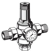
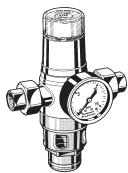
D06F Pressure reducing valve
Noise protected pressure reducing valve with setting scale. Maximum inlet pressure 16 bar, with brass filter bowl 25 bar, outlet pressure range 1.5 - 6.0 bar
A = With clear filter bowl up to 40 °C / 16 bar B = With brass filter bowl up to 70 °C / 25 bar
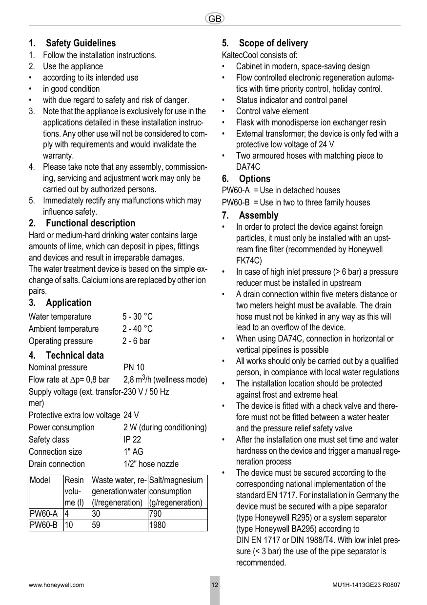
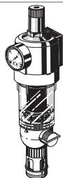
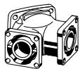
DA74C Rotatable piece
Available in 3/4", 1" and 11/4"
AS60-Y Y-adapter
Y-adapter for attachment to an already existing DA74C connection piece of a Honeywell filter; installation without having to open the pipe
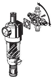
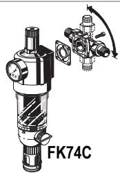
FK74C Filter combination
Combination of backwashable fine filter and pressure reducer with unloaded single seat valve
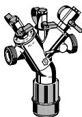
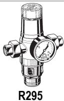
R295 Mechanical disconnector
To protect drinking water systems against back pressure, backflow and withdrawal. Protection against fluids up to and including fluid category 3 acc. to DIN EN 1717.
BA295 Backflow Preventer
To protect drinking water systems against back pressure, backflow and withdrawal. Protection against fluids up to and including fluid category 4 acc. to DIN EN 1717.
VC51-A Refill package (not shown)
Magnesium containing consumable for Kal-tecCool PW60A/B (2 bags of 25 kg each)
WS60-A Service Set
With replacement parts for annual maintenance
natural_image
Mechanical valve assembly diagram showing internal components and a handle (no text or labels)13.2 Mode assainissement
natural_image
Mechanical valve assembly diagram showing internal components and a shaft (no text or labels)natural_image
Technical illustration of a pressure regulator valve (no text or symbols on the diagram itself)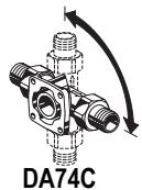
natural_image
Mechanical component diagram labeled DA74C, showing threaded and flanged parts with directional arrows (no text beyond label)
natural_image
Technical illustration of a pressure regulator with valve and fittings (no text or symbols)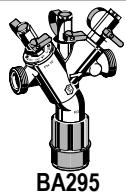
natural_image
Technical illustration of a mechanical valve or fitting with no visible text or symbols15. Accessoires
D06F Manodétendeur
• Pijl knippert = water inname
natural_image
Mechanical valve assembly diagram showing internal components and a shaft (no text or labels)13.2 Reinigings Modus
natural_image
Mechanical valve assembly diagram showing internal components and a shaft (no text or labels)natural_image
Technical illustration of a pressure regulator valve with three fittings and a central gauge (no text or symbols)D06F
DA74C

AS60-Y

natural_image
Technical illustration of a mechanical assembly with gears and shafts (no text or symbols)FK74C
natural_image
Technical illustration of a pressure regulator with valve and gauge (no text or symbols)R295

natural_image
Technical illustration of a mechanical valve assembly (no text or symbols)BA295
15. Accesoires
Automation and Control Solutions
Honeywell GmbH
Hardhofweg
D-74821 Mosbach
Phone: (49) 6261 810
Fax: (49) 6261 81309
http://europe.hbc.honeywell.com
www.honeywell.com
Manufactured for and on behalf of the
Environmental and Combustion Controls
Division of Honeywell Technologies Sàrl,
Ecublens, Route du Bois 37, Switzerland by
its Authorised Representative Honeywell
GmbH
MU1H-1413GE23 R0807
Subject to change without notice
Honeywell
Inhalt
- Safety Guidelines ...... 12
- Functional description ..... 12
- Application 12
- Technical data 12
- Scope of delivery 12
- Options 12
- Assembly 12
- Commissioning 13
- Operation 14
- Maintenance 15
- Working method during power failure 15
- Maintenance 15
- Further settings ...... 16
- Troubleshooting 17
- Accessories 19
Index


- Honeywell
- CE
- KONFORMITÄTSERKLÄRUNG DECLARATION OF CONFORMITY DECLARATION DE CONFORMITE
- Titel
- Zubehör
- D06F Druckminderer
- Functional description
- Application
- Technical data
- Scope of delivery
- Options
- Assembly
- Assembly instructions
- Commissioning
- Flush and Deaerate
- Filling the cabinet
- Time Setting
- Determining Water Hardness
- Manual Regeneration
- Operation
- Control Buttons, Display and Indicators
- Display
- Function keys
- Indicator lamps
- Display during Operation
- Display during Regeneration
- Phase
- Holiday Mode
- Guidelines for operation
- Maintenance
- Settings
- Time Setting
- Setting the water hardness
- Changing and/or omitting phases
- Changing and/or omitting phases
- Working method during power failure
- Maintenance
- Further settings
- Wellness Mode
- Cleaning Mode
- Accessories
- D06F Pressure reducing valve
- DA74C Rotatable piece
- AS60-Y Y-adapter
- FK74C Filter combination
- R295 Mechanical disconnector
- BA295 Backflow Preventer
- VC51-A Refill package (not shown)
- WS60-A Service Set
- Mode assainissement
- Accessoires
- D06F Manodétendeur
- Reinigings Modus
- Accesoires
- Automation and Control Solutions
- Inhalt
- Index
Brand : HONEYWELL
Model : KALTECCOOL PW60A-B
Category : Portable air conditioner