
BA298I-F - Network separator HONEYWELL - Free user manual and instructions
Find the device manual for free BA298I-F HONEYWELL in PDF.

| Product type | Network separator (disconnector) |
| Brand | HONEYWELL |
| Model | BA298I-F |
| Fluid | Water |
| Max. upstream pressure | 10.0 bar |
| Service pressure | 1.5 bar |
| Max. service temperature | 65 °C |
| Outlet connection | DN150 |
| Connection dimensions | DN65 to DN150 |
| Connection type | Flanged PN 10 |
| Mounting position | Horizontal, outlet connection downward |
| Body materials | Stainless steel, red brass, brass |
| Delivery contents | Body, check valves, drain valve, 3 ball valves |
| Applicable standard | DIN EN 1717 |
| Inspection | Every 6 months with kit TKA295 or TK295 |
| Maintenance | Every 1 to 3 years by a professional |
| Cleaning | Without solvents or alcohol, entrusted to an installer |
| Main spare parts | Drain valve (0901856), check valves (0901652/0901653), ball valve (0901662), gaskets (0904031/0904032), clip (0904033/0904034) |
| Recommended accessories | Strainer FY69P, test kits TK295/TKA295, valve replacement tool WBA-298 |
| Frost protection | Mounting location protected from frost |
| Drain opening differential pressure | 0.14 bar |
Frequently Asked Questions - BA298I-F HONEYWELL
User questions about BA298I-F HONEYWELL
0 question about this device. Answer the ones you know or ask your own.
Ask a new question about this device
Download the instructions for your Network separator in PDF format for free! Find your manual BA298I-F - HONEYWELL and take your electronic device back in hand. On this page are published all the documents necessary for the use of your device. BA298I-F by HONEYWELL.
USER MANUAL BA298I-F HONEYWELL
natural_image
Technical line drawing of a mechanical valve assembly (no text or symbols)
Keep instructions for later use!
11. Ersatzteile
BA298-F
- Follow the installation instructions.
- Use the appliance
• according to its intended use
- in good condition
• with due regard to safety and risk of danger.
3. Note that the appliance is exclusively for use in the applications detailed in these installation instructions. Any other use will not be considered to comply with requirements and would invalidate the warranty.
4. Please take note that any assembly, commissioning, servicing and adjustment work may only be carried out by authorized persons.
5. Immediately rectify any malfunctions which may influence safety.
2. Functional description
BA type backflow preventers are divided into three pressure zones. The pressure in zone ① is higher than in zone ②, which in turn is higher than in zone ③. A discharge valve is connected to zone ② which opens at the latest when the differential pressure between zones ① and ② falls to 0.14 bar. The water from zone ② discharges to atmosphere. In this way the danger of back pressure or back syphonage into the supply network is prevented. The pipework connection is interrupted and the drinking water network is protected.
3. Application
| Medium | Water |
| Inlet pressure | 10.0 bar |
| Operating pressure | 1.5 bar |
4. Technical data
Installation position Horizontal with discharge valve downwards
Max. operating temperature65 °C
Discharge pipe connection DN150
Connection size DN65 - DN150
5. Scope of delivery
The backflow preventer consists of:
- Housing
- Inlet and outlet check valves
- Discharge valve
- Three ball valves for the connection of a differential pressure gauge
6. Options
BA298-... FA = Standard version, in sizes DN 65 - 150 flanges in sizes, PN 10
BA298I-... FA = Standard version, in sizes DN 65 - 150 flanges in sizes, PN 10 Connection size
7. Assembly
7.1 Installations Guidelines
• Install shutoff valves before and after backflow preventer
- Install in horizontal pipework with the discharge valve downwards
- Ensure good access
o Simplifies maintenance and inspection
- Do not install in places where flooding can occur
- The installation environment should be protected against frost and ventilated well
• Install discharge pipework which has adequate capacity
- Where backflow preventers are installed care must be taken that discharges are safely carried away by the discharge pipework.
- Inlet pressure fluctuation, even without water draw off, can lead to brief operation of the discharge valve. It is therefore recommended that a pressure reducing valve be fitted upstream of the backflow preventer.
- No other unprotected potable water system may be connected downstream of the back flow preventer.
- Individual connections in the downstream system are not protected against backflow or back syphonage. If required, further protective measures can be installed as necessary to protect individual parts of the system
- The backflow preventer must be installed so that the discharge valve is above the surrounding maximum water table..

Use and type of installation according to DIN EN 1717
7.2 Assembly instructions
- Thoroughly flush pipework
- Ensure that connections on back flow preventer are clean
-
Install backflow preventer
-
Install in horizontal pipework with discharge connection directed downwards
- Note flow direction (indicated by arrow) o Install without tension or bending stresses
- Provide a straight section of pipework of at least five times the nominal valve size after the backflow preventer
- Observe required clearances
- Connect discharge pipework close coupled and without tight bends according to connection dimensions (see table)
- Install discharge pipework in such a way that the discharge connection and the discharge valve can be removed for inspection
8. Maintenance

We recommend a planned maintenance contract with an installation company

Maintenance of backflow preventer must be carried out by authorized personnel!
8.1 Inspection

• Frequency: every 6 month (depending on local operating conditions)
• To be carried out by an installation company
- Inspection with a test control unit and maintenance-set (see accessories)
The inspection should also include ancillary equipment such as strainers and shutoff valves.
8.1.1 Testing inlet check valve

Take note of the instructions of the test control unit TKA295 or TK295
- Procedure according to instruction of the test control unit TKA295 resp. TK295
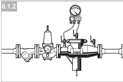
8.1.2 Testing discharge valve

Take note of the instructions of the test control unit TKA295 or TK295
- Procedure according to instruction of the test control unit TKA295 resp. TK295

Quick test for the discharge valve:
- Lower the inlet pressure o if the discharge valve opens (it drops), the function is o.k.
8.1.3 Testing outlet check valve

Take note of the instructions of the test control unit TKA295 or TK295
- Procedure according to instruction of the test control unit TKA295 resp. TK295
8.2 Maintenance

We recommend a planned maintenance contract with an installation company
In accordance with DIN EN 1717 a regular maintenance must be taken.

Frequency: every 1-3 years (depending on local operating conditions)
To be carried out by an installation company

Under no circumstances may check valves and discharge valves be disassembled. To doso is highly dangerous!
8.2.1 Discharge valve
- Close shutoff valve on inlet
- Release pressure on outlet side (e.g. through water tap)
- Close shut off valve on outlet
- Unscrew pressure control line
-
Loosen screws, pull the discharge connection downwards and unscrew the discharge valve with the aid of an oil filter strap wrench.
-
Remove the discharge valve o Clean or replace as required
-
Lubricate the 'O' ring well with grease, replace damaged 'O' rings
-
Reassemble in reverse order
-
Test function (see chapter inspection)
8.2.2 Check valve
- Close shutoff valve on inlet
- Release pressure on outlet side (e.g. through water tap)
- Close shut off valve on outlet
- Open the fixing clip
- Remove cover

Risk of injury - Check valves are under spring tension!
-
Remove the check valves o first unscrew the outlet and then the inlet check valve. An assembly tool is available as an accessory.
-
Fill with water and check for leakage o Leaking check valves must be replaced. They cannot be repaired
-
Reassemble in reverse order
• Well lubricate check valve 'O' ring with grease
- Do not damage 'O' ring during assembly
• The check valve tightening torque is 100 to 120 Nm
- Test function (see chapter inspection)
8.3 Cleaning

- To be carried out by an installation company - To be carried out by the operator

Do not use any cleaning agents containing solvents and/or alcohol to clean the plastic parts!

Detergents must not be allowed to enter the environment or the sewerage system!
- Procedure see Maintenance
9. Disposal
The backflow preventer consists of:
- Stainless steel
- Red bronze
- Brass

Observe the local requirements regarding correct waste recycling/disposal!
- Troubleshooting
| Disturbance | Cause | Remedy |
| Discharge valve opens without apparent reason | Pressure strokes in water supply system | Install a pressure reducing valve upstream the backflow preventer |
| Fluctuating inlet pressure | Install a pressure reducing valve upstream the backflow preventer | |
| Inlet check valve and/or discharge valves are dirty | Remove check valve or discharge valve and clean it | |
| Leaky inlet check valve | Replace check valve | |
| Discharge valve don’t close | Deposits on valve seat | Remove discharge valve, clean or replace it |
| Damaged ’o’ring | Remove discharge valve and replace ’o’ring | |
| Leaky discharge valve | Remove discharge valve, clean or replace it | |
| Discharge valve don’t open | Blocked pressure control pipe | Remove control pipe and clean it |
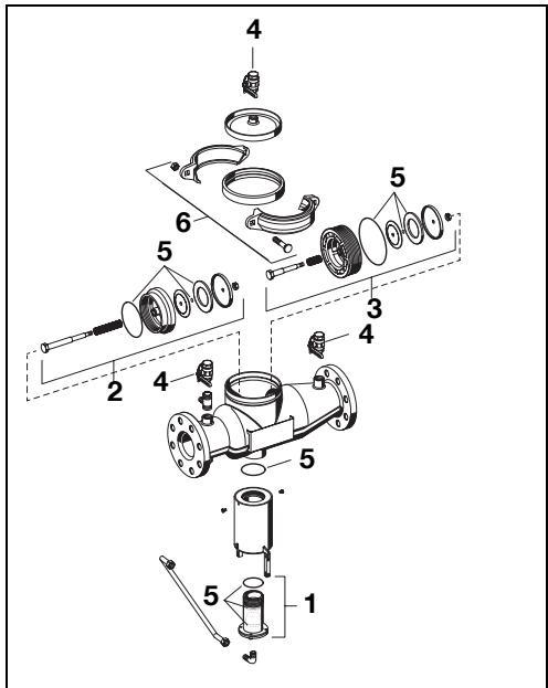
11. Spare Parts
BA298-F
1 Discharge valve DN65-150 0901855
2 Inlet check valve DN65 -100 0901650
DN150 0901654
3 Outlet check valve DN65-100 0901651
DN150 0901655
4 Ball valve DN65-150 0901659
5 Sealing set DN65-100 0904031
DN150 0904032
6 Clamp complete DN65-100 0904033
DN150 0904034
12. Spare Parts
BA298I-F
1 Discharge vlave DN65 -150 0901856
2 Inlet check valve DN65 -100 0901652
3 DN150 0901656
4 Outlet check valve DN65 -100 0901653
DN150 0901657
5 Ball valve DN65 -150 0901662
6 Sealing set DN65-100 0904031
DN150 0904032
7 Clamp complete DN65 -100 0904033
DN150 0904034
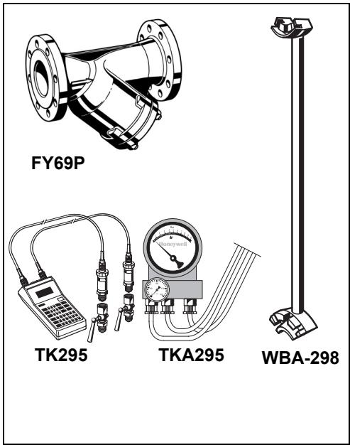
13. Accessories
FY69P Strainer
With double mesh, grey cast iron housing, powder coated inside and outside.
A = Mesh size approximately 0.5 mm
TK295 Test kit
Electronic pressure measuring device with digital indicator, battery-operated.
With case and accessories, ideal for inspection and maintenance of backflow preventer type BA.
TKA295 Test kit
Analogue pressure measuring device with differential pressure display.
With case and accessories, ideal for inspection and maintenance of backflow preventer type BA.
WBA-298 Check valve replacement tool
WBA-298-100 for connection sizes DN 65 - 100
WBA-298-150 for connection size DN 150
11. Części zamienne
BA298-F
Automation and Control Solutions
Honeywell GmbH
Hardhofweg
D-74821 Mosbach
Phone: (49) 6261 810
Fax: (49) 6261 81309
http://europe.hbc.honeywell.com
www.honeywell.com
Manufactured for and on behalf of the
Environmental and Combustion Controls Division of
Honeywell Technologies Sàrl, Rolle, Z.A. La Pièce 16,
Switzerland by its Authorised Representative Honeywell GmbH
MU1H-1218GE23 R0309
Subject to change
natural_image
Technical diagram of a mechanical piping system with pressure gauges and valves (no text or labels)| A | B | C | D | E | F | G | |
| 65 | 650 | 600 | 160 | 150 | 345 | 395 | 75 |
| 80 | 650 | 600 | 160 | 150 | 345 | 395 | 75 |
| 100 | 650 | 600 | 160 | 150 | 345 | 395 | 75 |
| 150 | 650 | 600 | 200 | 150 | 375 | 435 | 75 |
natural_image
Technical diagram of a mechanical piping system with gauges and valves (no text or labels)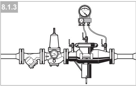
natural_image
Technical line drawing of a mechanical valve assembly with pressure gauge and actuator (no text or symbols)
D
- Safety Guidelines 6
- Functional description ...... 6
- Application 6
- Technical data 6
- Scope of delivery 6
- Options ...... 6
- Assembly 6
- Maintenance 7
- Disposal 8
- Troubleshooting 8
- Spare Parts BA298-F....9
- Spare Parts BA298I-F....9
- Accessories 9
F
- Ersatzteile
- Functional description
- Application
- Technical data
- Scope of delivery
- Options
- Assembly
- Installations Guidelines
- Assembly instructions
- Maintenance
- Inspection
- Testing inlet check valve
- Testing discharge valve
- Testing outlet check valve
- Maintenance
- Discharge valve
- Check valve
- Cleaning
- Disposal
- Spare Parts
- Spare Parts
- Accessories
- Części zamienne
- Automation and Control Solutions
- D
- F
Brand : HONEYWELL
Model : BA298I-F
Category : Network separator