
6210701X54N - Snowplows MURRAY - Free user manual and instructions
Find the device manual for free 6210701X54N MURRAY in PDF.
User questions about 6210701X54N MURRAY
0 question about this device. Answer the ones you know or ask your own.
Ask a new question about this device
Download the instructions for your Snowplows in PDF format for free! Find your manual 6210701X54N - MURRAY and take your electronic device back in hand. On this page are published all the documents necessary for the use of your device. 6210701X54N by MURRAY.
USER MANUAL 6210701X54N MURRAY
en Instruction Book - Snowthrower Model 6210701x54NA
fr Manuel de l'utilisateur - Chasse-neige modele 6210701x54NA
de Betriebsanleitung - Schneeschleuder modell 6210701x54NA
it Manuale di istruzioni - Spalaneve meccanico modello 6210701x54NA
Instruktieboek - Sneeuwblazer model 6210701x54NA
da Instruktionsbog - Sneslynge model 6210701x54NA
Bruksanvisning - Snøfreser modell 6210701x54NA
Användarhandbok - Snösunga modell 6210701x54NA
Ohjekirja - Lumilinko malli 6210701x54NA
es Manual de instrucciones - Quitanieves modelos 6210701x54NA
et Kasutusjuhend - Lumekoristaja mudel 6210701x54NA
el o O v - E k x i o v i o n p a M o v t o 6210701x54NA
Hu Kezelési utmutató - Hómaró modell 6210701x54NA
Lietošanas instrukciju - Sniega putejs modelis 6210701x54NA
It Instrukcija - Sniego valymo mašina i'rengimas modelis 6210701x54NA
pl Instrukcja obstugi - Odsnieżarka model 6210701x54NA
cs Navod na používanie - Snehová fréza, model 6210701x54NA
sk Návod na obsluhu - Snežá fréza, model 6210701x54NA
Knjizica z navodili - Snezná fréza, model 6210701x54NA
RuPykoBoDCTBO no 3KcIpyaTauN - CheroOuHCTnTeJb MoJeB 6210701x54NA

18
CONTENTS
HAZARD SYMBOLS AND THE MEANINGS 8
OPERATING SYMBOLS AND THEIR MEANINGS 8
TROUBLESHOOTING CHART 15
LIMITED WARRANTY 16
General Information
This instruction book is written for a person with some mechanical ability. Like most service books, not all the steps are described. Steps on how to loosen or tighten fasteners are steps anyone can follow with some mechanical ability. Read and follow these instructions before you use the unit.
Know your product: If you understand the unit and how the unit operates, you will get the best performance. As you read this manual, compare the illustrations to the unit. Learn the location and the function of the controls. To help prevent an accident, follow the operating instructions and the safety rules. Keep this manual for future reference.
IMPORTANT: Many units are not assembled and are sold in cartons. It is the responsibility of the owner to make sure the assembly instructions in this manual are exactly followed. Other units are purchased in an assembled condition. On assembled units, it is the responsibility of the owner to make sure the unit is correctly assembled. The owner must carefully check the unit according to the instructions in this manual before it is first used.
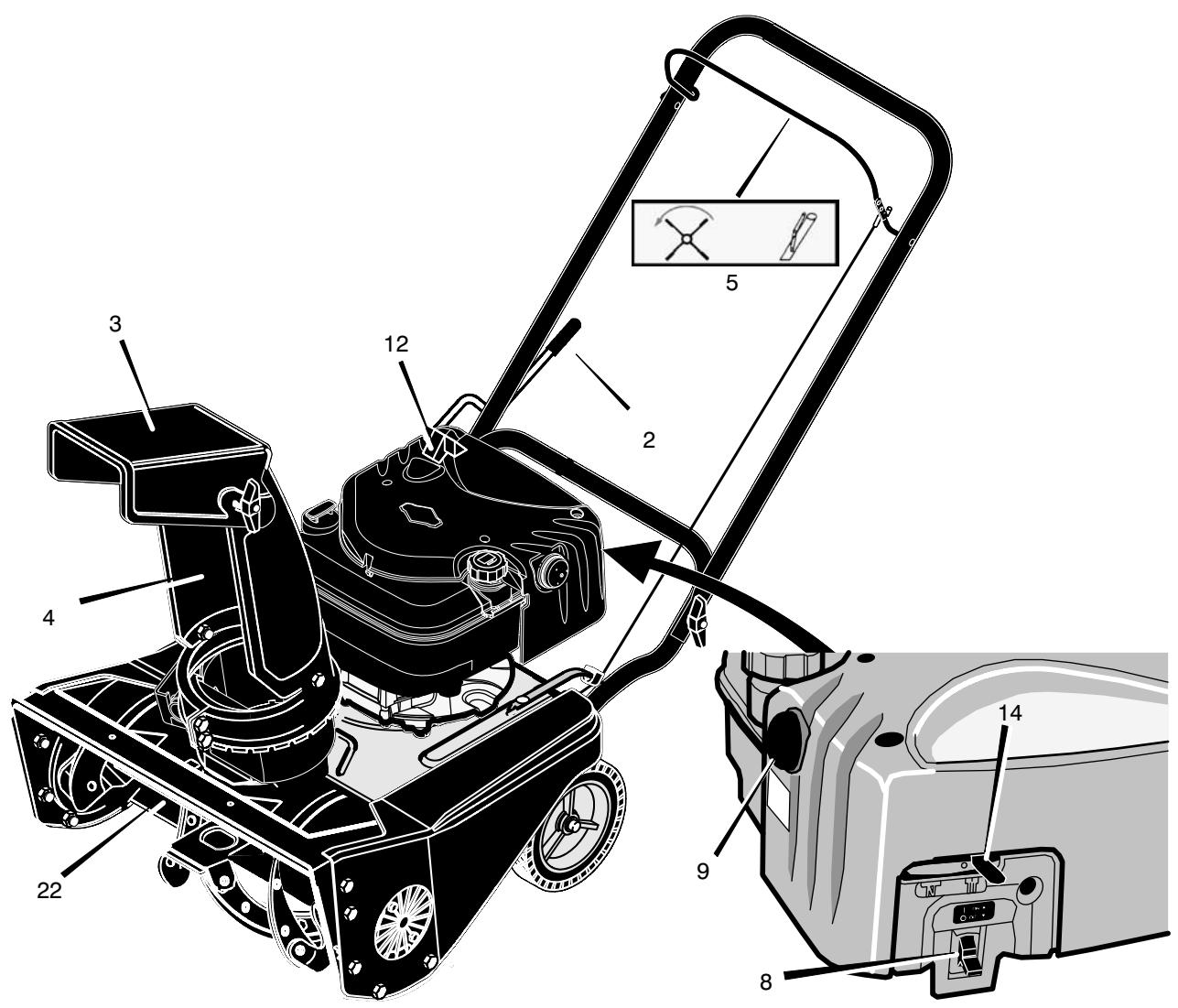
Controls & Equipment Features (see Figure 1)
Crank Assembly (2) - Changes the direction of the discharge chute.
Chute Deflector (3) - Changes the distance the snow is thrown.
Discharge Chute (4) - Changes the direction the snow is thrown.
Auger Drive Lever (5) - Starts and stops the auger (snow gathering and throwing) which also propels the snowthrower..
Engine Features
Stop Switch (8) - If equipped, move to the ON position to start the engine.
Primer Button (9) - Injects fuel directly into the carburetor for fast starts in cold weather.
Recoil Starter Handle (12) - Use to manually start the engine.
Choke Control (14) - Use to start a cold engine.
Murray www.briggsandstratton.com
MODEL NO.: 6210701x54NA
SKU No.:
YYYY MM DD:
SERIAL NO.:
3500 min-1
30 kg
C
Assembled in Suzhou, China 215218 by Limac for Briggs & Stratton Corporation
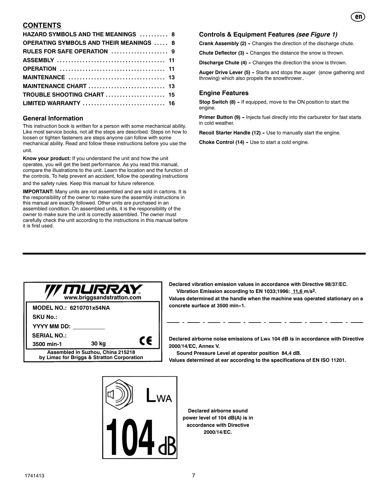
Declared vibration emission values in accordance with Directive 98/37/EC.
Vibration Emission according to EN 1033;1996: 11.6m / s^2
Values determined at the handle when the machine was operated stationary on a concrete surface at 3500 min-1.
Declared airborne noise emissions of LwA 104 dB is in accordance with Directive 2000/14/EC, Annex V.
Sound Pressure Level at operator position 84,4 dB.
Values determined at ear according to the specifications of EN ISO 11201.

Declared airborne sound power level of 104 dB(A) is in accordance with Directive 2000/14/EC.

This manual contains safety information to make you aware of the hazards and risks associated with snow
throwers, and how to avoid them. The snow thrower is designed and intended for removal of snow, and should not be used for any other purpose. It is important that you read and understand these instructions, and anyone operating the equipment read and understand these instructions.

WARNING
The engine exhaust from this product contains chemicals known to the State of California to cause cancer, birth defects, or other reproductive harm.
A signal word (DANGER, WARNING, or CAUTION) is used with the alert symbol to indicate the likelihood and the potential severity of injury. In addition, a hazard symbol may be used to represent the type of hazard.

DANGER indicates a hazard which, if not avoided, will result in death or serious injury.

WARNING indicates a hazard which, if not avoided, could result in death or serious injury.

CAUTION indicates a hazard which, if not avoided, might result in minor or moderate injury.
CAUTION, when used without the alert symbol, indicates a situation that could result in damage to the equipment.
Hazard Symbols and the meanings
These symbols are used on your equipment and defined in your operating manual. Review and understand the meanings. The use of one of these symbols combined with a signal word will alert you to potential hazards and how to avoid them.


Safety Alert - Identifies safety information about hazards that can result in personal injury.
Operator's Manual - Read and understand before performing any activity or running equipment.
Rotating auger

Fire

Explosion
Rotating impeller
Toxic fumes
Rotating gears
Thrown objects
Keep a safe distance from the equipment.


Shock
Hot Surface

Never reach into rotating parts.

Recommended ear protection for extended use.


Shut off engine and remove spark plug connector before performing maintenance or repair work.
Operating Symbols and their meanings
These symbols are used on your equipment and defined in your operating manual. It is important that you review and understand the meanings. Failure to understand the symbols might result in harm to you.

Oil

Fuel

On Off

Primer bulb

Throttle

Choke off

Choke on

Stop

Slow

Fast

Engage

Engage

Traction
Auger Collector

Auger Clutch

Drive Clutch
Discharge Chute

LEFT

RIGHT
Foward
Neutral
Reverse

Ignition On

Ignition Off

Ignition Key
Push to engage electric start

Electric
Start

Engine
Start

Engine Run

Engine Off

Engage

Disengage
Heated Grips
Chute Deflector

UP

DOWN
Safe Operation Practices for Snowthrowers
IMPORTANT: Safety standards require operator presence controls to minimize the risk of injury. Your snowthrower is equipped with such controls. Do not attempt to defeat the function of the operator presence control under any circumstances.
Training
- Read, understand, and follow all instructions on the machine and in the manuals before operating this unit. Be thoroughly familiar with the controls and the proper use of the equipment. Know how to stop the unit and disengage the controls quickly.
- Never allow children to operate the equipment. Never allow adults to operate the equipment without proper instruction.
- Keep the area of operation clear of all persons, particularly small children and pets.
- Exercise caution to avoid slipping or falling especially when operating in reverse.
Preparation
- Thoroughly inspect the area where the equipment is to be used and remove all doormats, sleds, boards, wires, and other foreign objects.
- Disengage all clutches and shift into neutral before starting the engine (motor).
- Do not operate the equipment without wearing adequate winter outer garments. Wear footwear that will improve footing on slippery surfaces. Avoid loose fitting clothing that can get caught in moving parts.
- Handle fuel with care; it is highly flammable.
a. Use an approved fuel container.
b. Never add fuel to a running engine or hot engine.
c. Fill fuel tank outdoors with extreme care. Never fill fuel tank indoors. Replace fuel cap securely and wipe up spilled fuel.
d. Never fill containers inside a vehicle or on a truck or trailer bed with a plastic liner. Always place containers on the ground, away from your vehicle, before filling.
e. When practical, remove gas-powered equipment from the truck or trailer and refuel it on the ground. If this is not possible, then refuel such on a trailer with a portable container, rather than from a gasoline dispenser nozzle.
f. Keep nozzle in contact with the rim of the fuel tank or container opening at all times, until refueling is complete. Do not use a nozzle lock-open device.
g. Replace gasoline cap securely and wipe up spilled fuel.
h. If fuel is spilled on clothing, change clothing immediately.
- Use extension cords and receptacles as specified by the manufacturer for all units with electric drive motors or electric starting motors.
- Adjust the collector housing height to clear gravel or crushed rock surfaces.
- Never attempt to make any adjustments while the engine (motor) is running (except when specifically recommended by manufacturer).
- Let engine (motor) and snowthrower adjust to outdoor temperatures before starting to clear snow.
- Always wear safety glasses or eye shields during operation or while performing an adjustment or repair to protect eyes from foreign objects that may be thrown from the machine.
Operation
- Do not put hands or feet near or under rotating parts. Keep clear of the discharge opening at all times.
- Exercise extreme caution when operating on or crossing gravel drives, walks or roads. Stay alert for hidden hazards or traffic.
- After striking a foreign object, stop the engine (motor), remove the wire from the spark plug, disconnect the cord on electric motors, thoroughly inspect snowthrower for any damage, and repair the damage before restarting and operating the snowthrower.
- If the unit should start to vibrate abnormally, stop the engine (motor) and check immediately for the cause. Vibration is generally a warning of trouble.
- Stop the engine (motor) whenever you leave the operating position, before unclogging the collector/impeller housing or discharge chute and when making any repairs, adjustments, or inspections.
- When cleaning, repairing, or inspecting, make certain the collector/impeller and all moving parts have stopped. Disconnect the spark plug wire and keep the wire away from the spark plug to prevent accidental starting.
- Do not run the engine indoors, except when starting the engine and for transporting the snowthrower in or out of the building. Open the outside doors; exhaust fumes are dangerous (containing CARBON MONOX-IDE, an ODDORLESS and DEADLY GAS).
- Exercise extreme caution when operating on slopes. Do not attempt to clear steep slopes.
- Never operate the snowthrower without proper guards, plates, or other safety protective devices in place and working.
- Never direct the discharge toward people or areas where property damage can occur. Keep children and others away.
- Do not overload the machine capacity by attempting to clear snow at too fast a rate.
- Never operate the machine at high transport speeds on slippery surfaces. Look behind and use care when operating in reverse.
- Disengage power to the collector/impeller when snowthrower is transported or not in use.
- Use only attachments and accessories approved by the manufacturer of the snowthrower (such as cabs, tire chains, etc.).
- Never operate the snowthrower without good visibility or light. Always be sure of your footing and keep a firm hold on the handles. Walk, never run.
- Never touch a hot engine or muffler.
- Never operate the snowthrower near glass enclosures, automobiles, window wells, drop-offs, and the like without proper adjustment of the snow discharge angle.
- Never direct discharge at bystanders or allow anyone in front of the unit.
- Never leave a running unit unattended. Always disengage the auger and traction controls, stop engine, and remove keys.
- Do not operate the unit while under the influence of alcohol or drugs.
- Keep in mind the operator is responsible for accidents occurring to other people or property.
- Data indicates that operators, age 60 years and above, are involved in a large percentage of power equipment-related injuries. These operators should evaluate their ability to operate the unit safely enough to protect themselves and others from injury.
- DO NOT wear long scarves or loose clothing that could become entangled in moving parts.
- Snow can hide obstacles. Make sure to remove all obstacles from the area to be cleared.
Children
Tragic accidents can occur if the operator is not alert to the presence of children. Children are often attracted to the unit and the operating activity. Never assume that children will remain where you last saw them.
- Keep children out of the area and under the watchful care of another responsible adult.
- Be alert and turn off if children enter the area.
- Never allow children to operate the unit.
- Use extra care when approaching blind corners, shrubs, trees, or other objects that may obscure vision.
Clearing A Clogged Discharge Chute
Hand contact with the rotating impeller inside the discharge chute is the most common cause of injury associated with snowthrowers. Never use your hand to clean out the discharge chute.
To clear the chute:
- SHUT OFF THE ENGINE.
- Wait 10 seconds to be sure the impeller blades have stopped rotating.
- Always use a clean out tool, not your hands.
Service, Maintenance And Storage
- Check shear bolts and other bolts at frequent intervals for proper tightness to be sure the equipment is in safe working condition.
- Never store the machine with fuel in the tank inside a building where ignition sources are present such as hot water and space heaters, or clothes dryers. Allow the engine to cool before storing in any enclosure.
- Always refer to operator's manual for important details if the snow-thrower is to be stored for an extended period.
- Maintain or replace safety and instruction labels as necessary.
- Run the machine a few minutes after throwing snow to prevent freeze-up of the collector/impeller.
-
If fuel is spilled, do not attempt to start the engine but move the machine away from the area of spillage and avoid creating any source of ignition until fuel vapors have dissipated.
-
Always observe safe refueling and fuel handling practices when refueling the unit after transportation or storage.
- Always follow the engine's manual instructions for storage preparations before storing the unit for both short and long term periods,
- Always follow the engine manual instructions for proper start-up procedures when returning the unit to service.
- Maintain or replace safety and instruction labels as necessary.
- Keep nuts and bolts tight and keep equipment in good condition.
- Never tamper with safety devices. Check their proper operation regularly and make necessary repairs if they are not functioning properly.
- Components are subject to wear, damage, and deterioration. Frequently check components and replace with manufacturer's recommended parts, when necessary.
- Check control operation frequently. Adjust and service as required.
- Use only factory authorized replacement parts when making repairs.
- Always comply with factory specifications on all settings and adjustments.
- Only authorized service locations should be utilized for major service and repair requirements.
- Never attempt to make major repairs on this unit unless you have been properly trained. Improper service procedures can result in hazardous operation, equipment damage and voiding of manufacturer's warranty.
- Check shear bolts (pins) and other bolts at frequent intervals for proper tightness to be sure the equipment is in safe working condition.
Emissions
- Engine exhaust from this product contains chemicals known, in certain quantities, to cause cancer, birth defects, or reproductive harm.
- If available, look for the relevant Emissions Durability Period and Air Index information on the engine emissions label.
Ignition System
- This spark ignition system complies with Canadian ICES-002.
Read and follow the assembly and adjustment instructions for your snow thrower. All fasteners are in the parts bag. Do not discard any parts or material until the unit is assembled.

WARNING: Before doing any assembly or maintenance to the snow thrower, remove the wire from the
spark plug.
NOTE: In this instruction book, left and right describe the location of a part from the operator's position behind the unit.
NOTE: Torque is measured in foot pounds (metric N.m). This measurement describes how tight a nut or bolt must be. The torque is measured with a torque wrench.
NOTE: Illustrations are located on page 2 and on pages 3 through 6.
Tools Required
1 Knife
1 Pliers
How To Remove The Snow Thrower From The Carton
- Locate and remove the container of oil.
- Locate all parts that are packed separately and remove from the carton.
- Remove and discard the packing material from around the snow thrower.
- Cut down all four corners of the carton and lay the side panels flat.
- Hold onto the lower handle and pull the snow thrower off the carton.
CAUTION: DO NOT back over cables.
- Remove the packing material from handle assembly. Remove the lower insert from the axle.
How To Assemble The Handle
- Remove the packing material from the upper and lower handles.
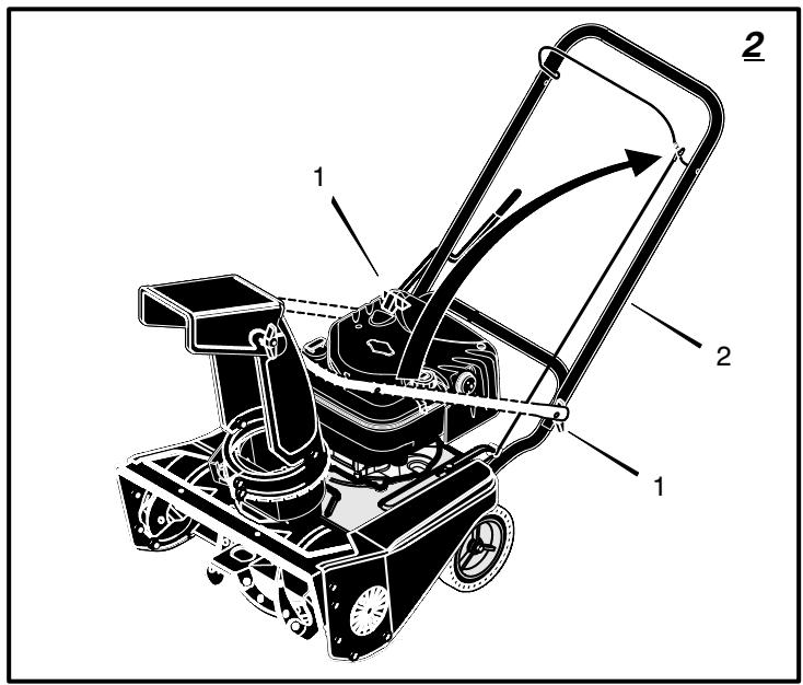
- (Figure 2) Loosen the knobs (1) on each side of the handle (2).
- Raise the upper handle (2) to the operating position. Hold the upper handle (2) apart to prevent scratching the lower handle.
NOTE: Make sure the auger drive cable is not caught between the upper and lower handle.
- Tighten the knobs (1).
How To Prepare The Engine

WARNING: Follow the engine manufacturer's instructions for the type of fuel and oil to use. Always
use a safety fuel container. Do not smoke when adding fuel to the fuel tank. When inside an enclosure, do not fill the fuel tank. Before you add the fuel, stop the engine. Let the engine cool for several minutes.
See the engine manufacturer's instructions for the type of fuel and oil to use. Before you use the unit, read the information on safety, operation, maintenance, and storage.
1741413
NOTE: Engine horsepower ratings may vary by engine adjustments, manufacturing variances, altitude, atmospheric conditions, fuel and maintenance.
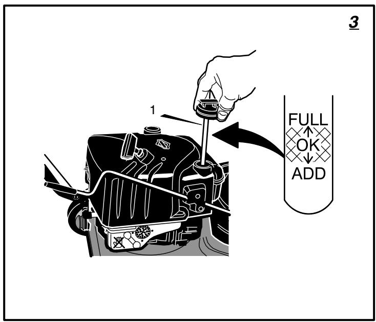
Add Oil To The Engine (Figure 3)
NOTE: Engine may already contain some residual oil. Check frequently when filling the crankcase. DO NOT overfill.
The snow thrower was shipped with a container of 5W30 motor oil. This oil must be added to the engine before operating.
- Make sure the unit is level.
- Remove the oil fill cap/dipstick (1) and fill the crankcase to "FULL" line on dipstick. DO NOT overfill.
- Tighten the oil fill cap/dipstick (1) securely each time you check the oil level.
NOTE: Synthetic oil can assist with starting in extreme cold temperatures. Synthetic 5W30 is acceptable for all temperatures. DO NOT mix oil with petrol.
Add Petrol To The Engine
This engine is certified to operate on petrol. Exhaust Emission Control System: EM (Engine Modifications).

WARNING: Alcohol blended fuels (called gasohol or those using ethanol or methanol) can attract
moisture which leads to separation and formation of acids during storage. Acidic gas can damage the fuel system of an engine while in storage.
NOTE: To avoid engine problems, the fuel system must be emptied before storage for 30 days or longer. Start the engine and let it run until the fuel lines and carburetor are empty. Use fresh fuel next season. See the Storage section in this manual for additional information.
Fill the fuel tank only with a fresh, clean, unleaded regular, unleaded premium, or reformulated automotive petrol with a minimum of 85 octane. DO NOT use leaded petrol. Make sure that the container you pour the petrol from is clean and free from rust or other foreign particles. Never use petrol that may be stale from long periods of storage in the container.
Before You Operate
Before you operate your new snow thrower, please review the following checklist:
Make sure all assembly instructions have been completed.
Make sure the discharge chute rotates freely.
Make sure that no loose parts remain in the carton.
As you learn how to properly use the snow thrower, pay extra attention to the following important items.
Make sure the engine oil is at the proper level. For the type engine oil to use, see the Engine Manufacturer's manual.
Make sure gas tank is filled properly with clean, fresh, unleaded petrol with a minimum of 85 octane.
- Become familiar with the location of all controls and understand their function.
Before starting the engine, make sure all controls operate correctly.
OPERATION
NOTE: Illustrations are located on page 2 and on pages 3 through 6.
CAUTION: Use only attachments and accessories approved by the manufacturer of the snow thrower (such as tire chains, electric start kits, etc.).
Know Your Snow Thrower (Figure 1)
Read this Instruction Book and safety rules before operation the snow thrower. Compare the illustration with your snow thrower to familiarize yourself with the location of various controls and adjustments.
How To Control
The Discharge Of The Snow

WARNING: Never direct the discharge of snow toward bystanders.

WARNING: Always stop the engine before unclogging the discharge chute or the auger housing and be
fore leaving the snow thrower.
- (Figure 1) Turn the crank assembly (2) to change the discharge direction of the snow.
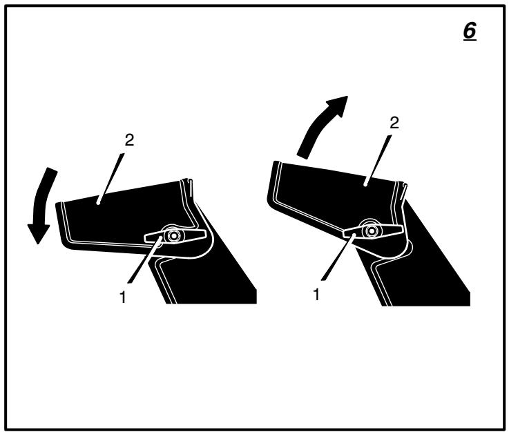
- (Figure 6) Loosen the wing knob (1) on the chute deflector (2).
- Move the chute deflector (2) up for more distance or down for less distance.
- Tighten the wing knob (1).
How To Throw Snow (Figure 1)
- Engage the auger drive lever (5).
- To stop throwing snow, release the auger drive lever (5).

WARNING: The operation of any snow thrower can result in foreign objects being thrown into the eyes, can result in severe eye damage.
Always wear safety glasses or eye shields while operating the snow thrower. We recommend standard safety glasses or use a wide vision safety mask over your glasses.
How To Stop Discharging Snow (Figure 1)
- To stop discharging snow, release the auger drive lever (5).
NOTE: If the snow thrower continues to slowly move forward, see "How To Adjust The Auger Control Cable" in the Maintenance Section. - To stop the engine, push the stop switch (8) to the off position.
CAUTION: To stop the engine, do not move the choke control to CHOKE position. Backfire or engine damage can occur.
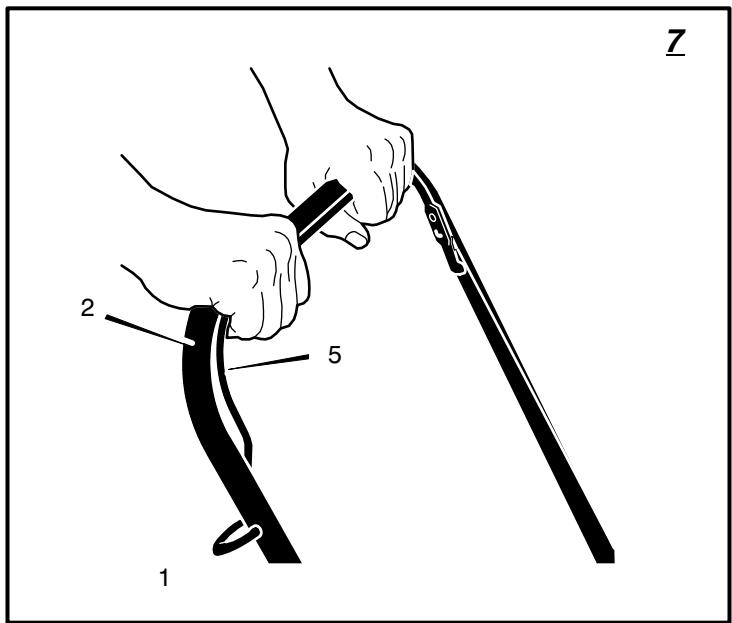
How To Move Forward (Figure 7)
- Hold the auger drive lever (5) against the handle (2). The auger will begin rotating.
- To go forward, raise the handle (2) to allow the rubber auger blades to contact the ground. Maintain a firm hold on the handle (2) as the snow thrower starts to move forward. Guide the snow thrower by moving the handle (2) either left or right. Do not attempt to push the snow thrower.
- To stop, release the auger drive lever (5). NOTE: If the auger continues to rotate, see "How To Adjust The Auger Control Cable" in the Maintenance section.
Before Starting The Engine
- Before you service or start the engine, familiarize yourself with the snow thrower. Be sure you understand the function and location of all controls.
- Make sure that all fasteners are tight.
- Make sure gas tank is filled properly with clean, fresh, unleaded petrol with a minimum of 85 octane.
- Become familiar with the location of all controls and understand their function.
- Before starting the engine, make sure all controls operate currently.
How To Stop The Engine (Figure 1)
To stop the engine, push the stop switch (8) to the off position.
CAUTION: To stop the engine, do not move the choke control to CHOKE position. Backfire or engine damage can occur.
How To Start The Engine (Figure 1)
Make sure that the engine oil is at FULL mark on dipstick. The engine is equipped with a recoil starter. Before starting the engine, make certain that you have read the following information. If engine floods, set the choke to the OPEN/ RUN position and crank until the engine starts.

WARNING: Rapid retraction of the starter cord (kickback) will pull your hand or arm toward the en
gine faster than you can let go of the starter cord.
- When starting the engine, slowly pull the starter cord until resistance is felt. Then, rapidly pull the starter cord.
- Make sure components; such as impellers, pulleys or sprockets, are securely attached.
How To Start A Cold Engine (Figure 1)
- (Figure 1) Push the stop switch (8) to the ON position.
- When starting the engine, do not engage the auger drive lever.
- Move the choke control (14) to the FULL choke position.
- Push the primer button (9) two times. Remove finger from the primer button (9) between primes.
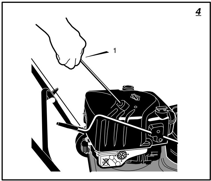
- (Figure 4) Slowly pull the recoil starter handle (1) until resistance is felt and then pull rapidly to start the engine. Do not allow the recoil starter handle (1) to snap back. Slowly return the recoil starter handle (1).
1741413
NOTE: In temperatures below 0^ , allow the engine to warm up for several minutes before blowing snow.

WARNING: Never run the engine indoors or in enclosed, poorly ventilated areas. Engine exhaust comparonoxide, an odorless and gas. Keep hands, feet, hair and clothing away from any moving parts on the engine or the snow thrower. Temperature of muffler and nearby may exceed 150^ . Avoid these
How To Start A Warm Engine (Figure 1)
If an engine has been running and is still warm, leave the choke control (14) in the off position and do not push the primer button (9). If the engine fails to start, follow the instructions "How To Start A Cold Engine".
NOTE: Do not use the primer button (9) to start a warm engine.
How To Start An Engine With A Frozen Electric Starter (Figure 1)
If the starter is frozen and will not turn the engine, follow the instructions below.
- Pull out the recoil starter handle (12) as far as possible.
- Quickly release the recoil starter handle (12). Allow the recoil starter handle (12) to snap back against the recoil starter.
If the engine still fails to start, repeat the two previous steps until the engine starts. Then, continue with the directions "How To Start A Cold Engine".
To help prevent the possible freeze-up of the recoil starter and of the engine controls, proceed as follows after each snow removal job.
- Before storing, run the snow thrower a few minutes to prevent freeze-up of the auger/ impeller.
- With engine off, allow engine to cool for several minutes.
- Pull starter rope very slowly until resistance is felt, then stop. Allow the starter rope to recoil. Repeat three times.
- With the engine not running, wipe all snow and moisture from the carburetor cover in area of controls and levers. Also, move the choke control and starter handle several times.
How To Remove Snow or Debris From The Auger Housing (Figure 1)

WARNING: Do not attempt to remove snow or debris that may become lodged in auger housing, taking the following precautions.
- Release the auger drive lever (5).
- To stop the engine, move the stop switch (8) to the stop position.
- Disconnect the spark plug wire.
- Do not place your hands in the auger housing (22) or the discharge chute (4). Use a pry bar to remove any snow or debris.
Snow Throwing Tips
- This snow thrower will propel itself forward when the handle is raised enough to cause the auger blades to contact the ground. The auger should stop when auger control bar is released. If it does not stop, see "How To Adjust The Auger Control Cable" in the adjustment section.
- Most efficient snow throwing is accomplished when the snow is removed immediately after if falls.
CAUTION: Do not overload the machine capacity by attempting to clear snow at too fast a rate.
- For complete snow removal, slightly overlap each previous path.
- Whenever possible, discharge the snow down wind.
- The distance the snow will be discharged can be adjusted by moving the discharge chute deflector. Raise the deflector for more distance or lower the deflector for less distance.
- In windy conditions, lower the chute deflector to direct the discharged snow close to the ground where it is less likely to blow into unwanted areas.
- For safety and to prevent damage to the snow thrower, keep the area to be cleared free of stones, toys and other foreign objects.
- Do not use the auger propelling feature when clearing gravel or crushed rock driveways. Move the handle down to slightly raise the auger.
- The forward speed of the snow thrower is dependent on the depth and weight of the snow. Experience will establish the most effective method of using the snow thrower under different conditions.
- After each snow throwing job, allow the engine to run for a few minutes. The snow and accumulated ice will melt off the engine.
- Clean the snow thrower after each use.
- Remove ice, snow and debris from the entire snow thrower. Flush with water to remove all salt or other chemicals. Wipe snow thrower dry.
Dry And Average Snow
- Snow up to eight inches deep can be removed rapidly and easily by walking at a moderate rate. For snow or drifts of a greater depth, slow your pace to allow the discharge chute to dispose of the snow as rapidly as the auger receives the snow.
- Plan to have the snow discharged in the direction the wind is blowing.
Wet Packed Snow
Move slowly into wet, packed snow. If the wet, packed snow causes the auger to slow down or the discharge chute begins to clog, back off and begin a series of short back and forth jabs into the snow. These short back and forth jabs, four to six inches, will "belch" the snow from the chute.
Snow Banks And Drifts
In snow of greater depth than the unit, use the same "jabbing" technique described above. Turn the discharge chute away from the snow bank. More time will be required to remove snow of this type than level snow.
MAINTENANCE CHART
CUSTOMER RESPONSIBILITIES
| SERVICE RECORDS Fill in dates as you complete regular service. | Before Each Use | First 2 Hours | Every 5 Hours | Every 10 Hours | Every 25 Hours | Each Season | Before Storage | SERVICE DATES |
| Check And Tighten All Screws and Nuts | ✓ | ✓ | ||||||
| Check Spark Plug | ✓ | ✓ | ||||||
| Check Drive Belt | ✓ | |||||||
| Check Fuel | ✓ | |||||||
| Drain Fuel | ✓ | |||||||
| Lubricate Chute Control Flange | ✓ | |||||||
| Check Adjustment of Auger Control Cable | ✓ | |||||||
| Auger Drive Belt | ✓ |
MAINTENANCE
NOTE: Illustrations are located on page 2 and on pages 3 through 6.
Use the following maintenance section to keep your unit in good operating condition.
All the maintenance information for the engine is in the engine manufacturer's instructions. Before you start the engine, read this book.

WARNING: Before you make an inspection, adjustment (except carburettor), or repair, disconnect
the wire from the spark plug.
Emissions Control
Maintenance, replacement, or repair of the emissions control devices and systems may be performed by any non-road engine repair establishment or individual. However, to obtain a "no charge" emissions control service, the work must be performed by a factory authorized dealer. See the Emissions Warranty.
General Recommendations
The warranty on this snow thrower does not cover items that have been subjected to operator abuse or negligence. To receive full value from the warranty, the operator must maintain the snow thrower as instructed in this manual.
Some adjustments must be made periodically to properly maintain the snow thrower.
After Each Use
- Check for any loose or damaged parts.
- Tighten any loose fasteners.
Check and maintain the auger. - Check controls to make sure they are functioning properly.
If any parts are worn or damaged, replace immediately. - Check all safety and instruction decals and labels. Replace any decals or labels that are missing or cannot be clearly read.
1741413
All adjustments in the Maintenance section of this manual should be checked at least once each season.
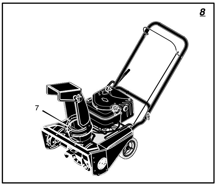
How To Remove The Top Cover (Figure 8)
- Remove the five screws (1) from the top cover (2).
- Remove the top cover (2).
- To install the top cover (4), reverse the above steps.
Lubrication
Before Storage (Figure 8)
- Lubricate the clute control flange (7). Apply a clinging type of grease such as Lubriplate.
How To Adjust The Auger Control Cable
The auger control cable is adjusted at the factory. During normal use, the auger control cable can become stretched and the auger drive lever will not properly engage or disengage the auger.
-
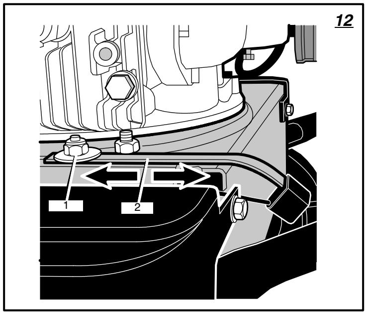
(Figure 12) Loosen the nut (1) that holds the cable tension spring (2).
-
Slide the cable tension spring (2) toward the rear of the unit until all cable slack is removed.
NOTE: The auger control cable is properly adjusted when the free cable slack is removed and there is no tension on the idler arm.
- Tighten the nut (1) that holds the cable tension spring (2).
If belt stretch has occurred, move the end the auger control cable to the outside hole as follows:
- (Figure 12) Loosen the nut (1) that holds the cable tension spring (2).
- Move the cable tension spring (2) toward the front of the unit to achieve maximum cable slack.
-
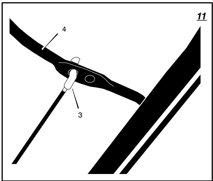
(Figure 11) Remove the upper end of the auger control cable (3) from the auger drive lever (4).
-
Install the auger control cable (3) in the hole shown in Figure 11.
- (Figure 12) Slide the cable tension spring (2) toward the rear of the unit until all cable slack is removed.
NOTE: The auger control cable (3) is properly adjusted when the free cable slack is removed and there is no tension on the idler arm.
- Tighten the nut (1) that holds the cable tension spring (2).
- To check the adjustment, start the snow thrower. Make sure the auger does not rotate when the auger drive lever is released.
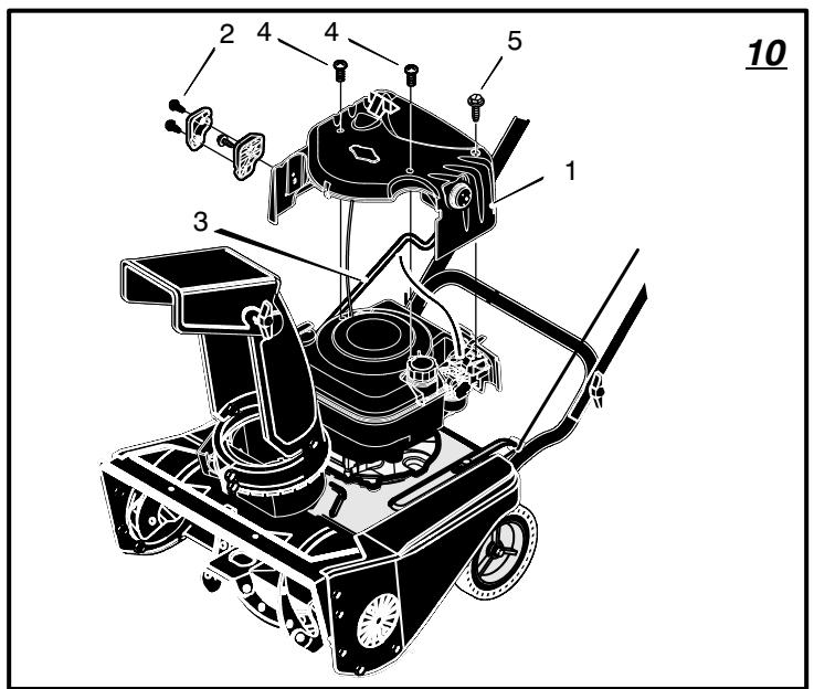
How To Remove The Top Cover (Figure 10)
There are no adjustments under the top cover (1). To clean the engine cooling system, follow the steps below to remove the top cover (1).
- Remove screws (2) that attach the rod support clamp the the top cover (1). Pivot the crank assembly rod (3) up and lay on unit.
- Remove screws (4).
- Remove attachment screws (5).
- Remove the top cover (1).
- To install the top cover (1), reverse the above steps.
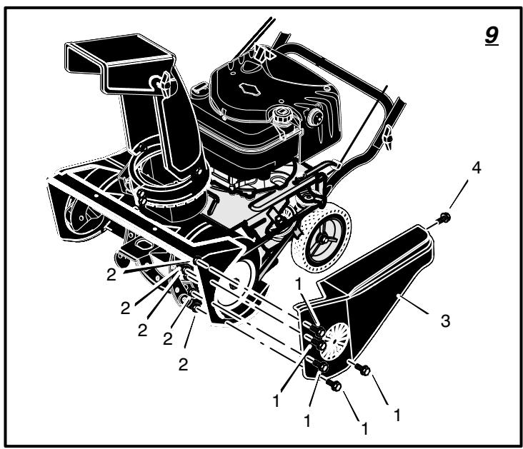
How To Remove The Belt Cover (Figure 9)
- Remove the screws (1) and nuts (2) from the belt cover (3).
- Remove attachment screw (4) from the rear of the belt cover (3).
- Remove the belt cover (3) from the unit.
- To install the belt cover (3), reverse the above steps.
NOTE: The belt cover (3) has belt guides moulded onto the inside of the belt cover (3). When you install the belt cover (3), engage the auger drive lever to tighten the belt against the pulley. This will provide adequate clearance for the belt guides when installing the belt cover (3).
How To Replace The Auger Drive Belt
The drive belt is of special construction and must be replaced with an original factory re
placement belt available from your nearest authorized service center.
If the auger drive belt is damaged, the snowthrower will not discharge snow and will not move forward. Replace the damaged belt as follows:
- Disconnect the spark plug wire.
- Remove the belt cover. See "How To Remove The Belt Cover".
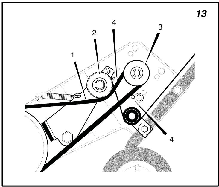
- Note the path of the auger drive belt (1). For assistance, a diagram decal is provided.
- (Figure 14) Remove the belt guide screw (2) and the belt guide (3). To remove the belt guide (3), rotate the belt guide (3) down.
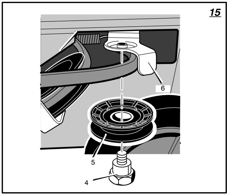
- (Figure 15) Remove the idler screw (4) and idler pulley (5) from the idler arm (6).
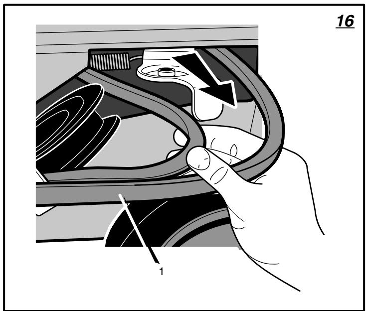
- (Figure 16) Remove the auger drive belt (1) from the engine pulley and pull through side of motor box.
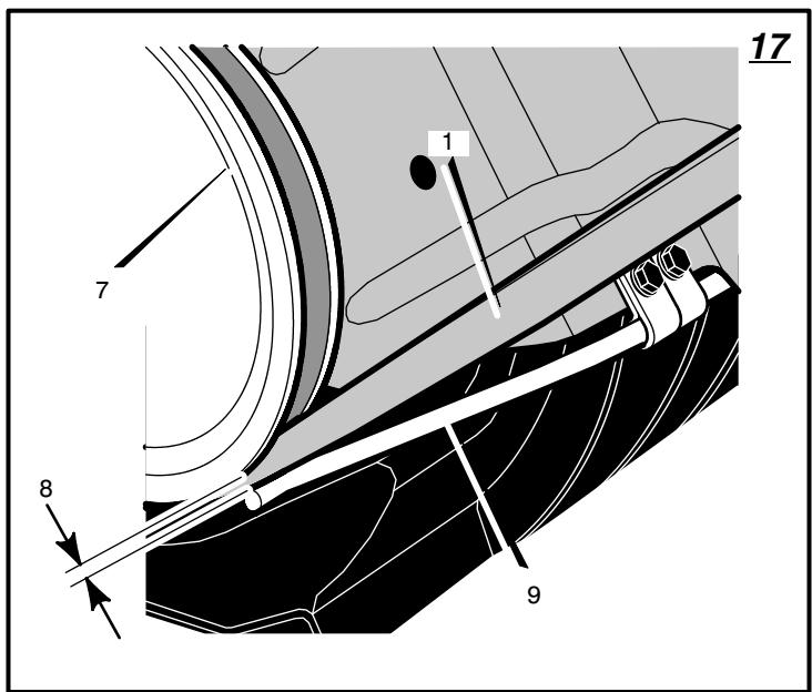
- (Figure 17) To remove the auger drive belt (1) from the impeller pulley (7), move the idler arm to the engaged position. This will provide clearance (8) between the impeller pulley (7) and the brake arm (9) to remove the auger drive belt.
- To install a new auger drive belt (1), reverse the above steps.
- Check the adjustment of the auger drive cable. See "Adjust Auger Control Cable".
How To Remove The Auger
- Remove the belt cover. See "How To Remove The Belt Cover".
- Remove the auger drive belt. See "How To Replace The Auger Drive Belt".
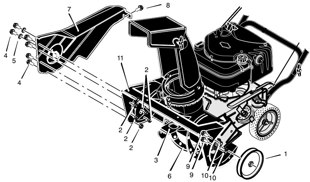
- (Figure 18) Remove the auger pulley (1) from the auger shaft (threads are left hand; turn clockwise to remove).
- To keep the auger (6) from rotating, set a 2^ × 4^ piece of wood on the center paddle (3) to secure auger (6).
- Remove bolts (4), washer (5), and nuts (2) from front of right cover (7).
- Remove screw (8) from back of right cover (7).
- Remove bolts (9) and nuts (10).
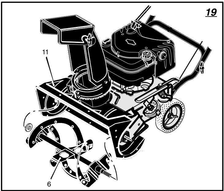
- (Figure 19) Slide the auger (6) out of the right side of the auger housing (11).
- Slide the auger (6) out of the bearing on the left side of the auger housing (11).
- To install auger (6), reverse the above steps.
Lubrication
How To Check The Engine Oil (Figure 3)
Check the oil level before starting the engine and after each eight (8) hours of continuous use.
- Make sure the unit is level.
- Remove the oil fill cap/dipstick (1) and fill the crankcase to "FULL" line on dipstick. DO NOT overfill.
- Tighten the oil fill cap/dipstick (1) securely each time you check the oil level.
NOTE: Synthetic oil can assist with starting in extreme cold temperatures. Synthetic 5W30 is acceptable for all temperatures. DO NOT mix oil with petrol.
How To Change The Engine Oil
Change the engine oil every fifty (50) hours or at least once a year if the snow thrower is not used for fifty (50) hours.
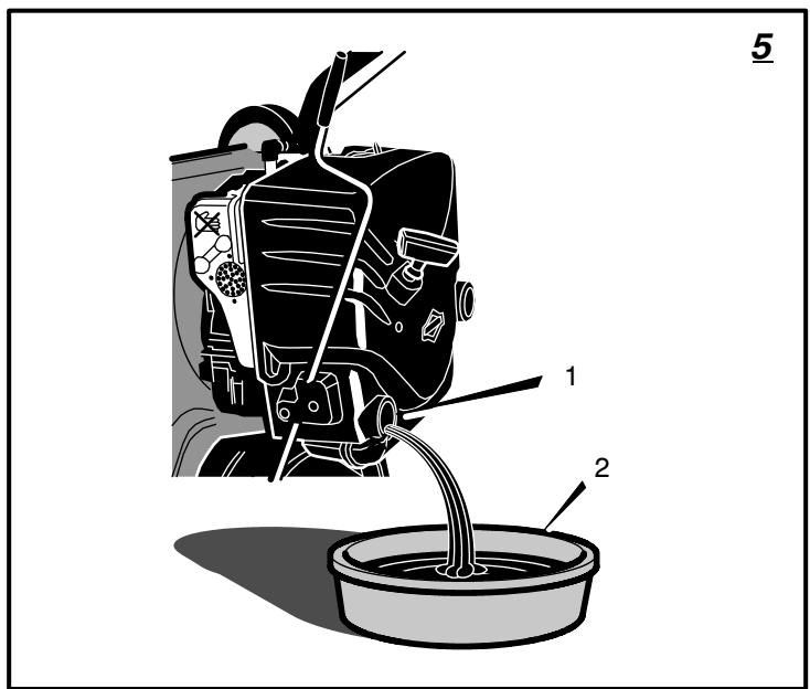
To change the engine oil, the engine must be tilted forward and the oil drained from the oil fill tube. Change oil when the engine is warm.
- (Figure 5) Lift the rear of the snowthrower and tilt the unit forward. In the correct position, the snowthrower will be setting on the front of the auger housing.
- Put an oil drain pan (1) under the oil fill tube (2).
- Carefully remove the oil fill cap/dipstick. Oil will begin to flow into the oil drain pan (2).
- After all the oil has drained from the engine, set the snowthrower in the upright operating position.
- (Figure 3) Fill the engine with S.A.E. 5W30 oil. Make sure the oil reaches the FULL mark on the oil fill cap/dipstick. DO NOT OVER-FILL.
NOTE: Synthetic oil can assist with starting in extreme cold temperatures. Synthetic 5W30 is acceptable for all temperatures. DO NOT mix oil with petrol.
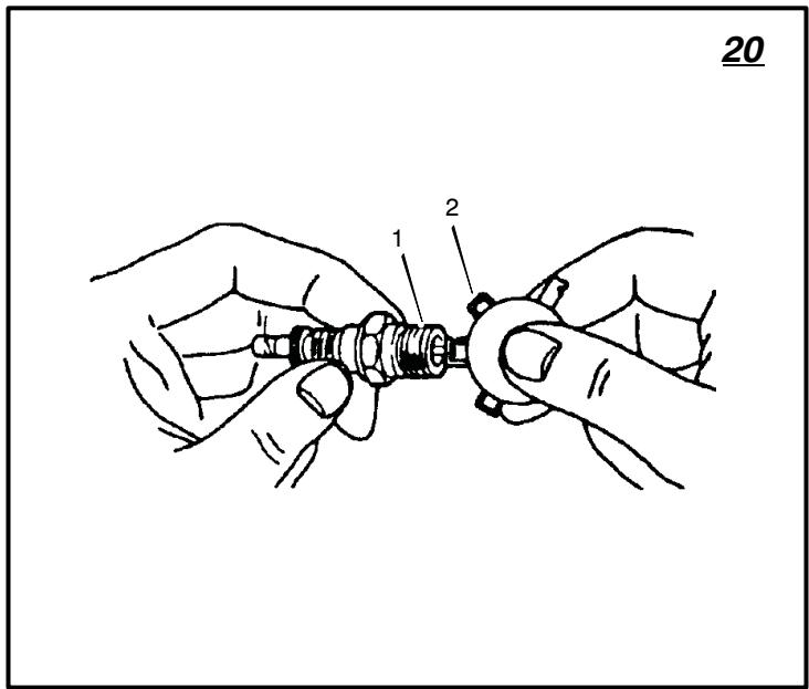
How To Replace The Spark Plug (Figure 20)
NOTE: This spark ignition system meets all requirements of the Canadian Interference-Causing Equipment Regulations.
NOTE: This engine complies with all current Australian and New Zealand limitations electromagnetic interference.
Check the spark plug (1) every twenty-five (25) hours. Replace the spark plug (1) if the electrodes are pitted or burned, if the porcelain is cracked, or every 100 hours of use.
- Make sure the spark plug (1) is clean. Clean the spark plug (1) by carefully scraping the electrodes (do not sand blast or use a wire brush).
- Check the spark plug (1) gap with a feeler gauge (2) and reset gap to 0.030" if necessary..
- Before installing the spark plug (1), coat the threads lightly with oil for easy removal. Tighten the spark plug (1) to a torque of 15 foot-pounds.
How To Prepare The Snow Thrower For Storage

WARNING: Do not remove petrol while inside a building, near a fire, or while you smoke. Petrol fumes use an explosion or a fire.
If the snow thrower is to be stored for an extended period, refer to the engine manufactur
er's operating manual (included with some models) for important maintenance or storage details.
- Drain the fuel tank.
- Let the engine run until it is out of gasoline.
- Never store the snow thrower with fuel in the tank inside a building where ignition sources are present such as hot water and space heaters, clothes dryers, and the like. Allow the engine (motor) to cool before storing in any enclosure.
- Drain the oil from the warm engine. Fill the engine crankcase with new oil.
- Remove the spark plug from the cylinder. Pour one ounce of oil into the cylinder. Slowly pull the recoil-start grip so that the oil will protect the cylinder. Install a new spark plug in the cylinder.
- Thoroughly clean the snow thrower.
- Lubricle all lubrication points. See the Maintenance section.
- Be sure that all nuts, bolts and screws are securely fastened. Inspect all visible moving parts for damage, breakage and wear. Replace if necessary.
- Cover the bare metal parts of the blower housing and auger with spray rust preventative lubricant.
- Put the unit in a building that has good ventilation.
- If the machine must be stored outdoors, block up the snow thrower to be sure the entire machine is off the ground.
- Cover the snow thrower with a suitable protective cover that does not retain moisture. Do not use plastic.
How To Order Replacement Parts
The replacement parts are shown either on the back pages of this Instruction Book or in a separate Parts List Book.
Use only manufacturer's authorized or approved replacement parts. The letter placed on the end of the part number denotes the type of finish for the part, C for chrome, Z for zinc, a PA for purchased assembly. It is important that you include this when ordering a part. Do not use attachments or accessories not specifically recommended for this unit. In order to obtain proper replacement parts you must supply the model number (see nameplate).
Warranty service is available only through Authorized Service Dealers. Locate your nearest dealer in our locator map at www.murray.com.
Replacement parts for the engine, transaxle, or transmission, are available from the manufacturer's authorized service center found in the yellow pages of the telephone directory. Also, see the individual engine or transmission warranties to order replacement parts.
When ordering the following information is required:
(1) The Model Number
(2) Serial Number
(3) Part Number
(4) Quantity
| TROUBLE | CAUSE | CORRECTION |
| Difficult starting | Defective spark plug. | Replace spark plug. |
| Water or dirt in fuel system. | Use carburetor bowl drain to flush and refill with fresh fuel. | |
| Engine runs erratic | Blocked fuel line, empty gas tank, or stale gasoline | Clean fuel line; check fuel supply; add fresh gasoline |
| Engine stalls | Unit running on CHoke. | Set choke lever to RUN position. |
| Engine runs erratic; Loss of power | Water or dirt in fuel system. | Use carburetor bowl drain to flush and refill with fresh fuel. |
| Excessive vibration | Loose parts: damaged impeller | Stop engine immediately and disconnect spark plug wire. Tighten all bolts and make all necessary repairs. If vibration continues, have the unit serviced by a competent repairman. |
| Unit fails to propel itself | Drive belt loose or damaged. | Replace drive belt. |
| Unit fails to discharge snow | Auger drive belt loose or damaged. | Adjust auger drive belt; replace if damaged. |
| Auger control cable not adjusted correctly. | Adjust auger control cable. | |
| Discharge chute clogged. | Stop engine immediately and disconnect spark plug wire. Clean discharge chute and inside of auger housing. | |
| Foreign object lodged in auger | Stop engine immediately and disconnect spark plug wire. Remove object from auger. |
BRIGGS & STRATTON CORPORATION OWNER WARRANTY POLICY
Effective January 1, 2006 replaces all undated Warranties and all Warranties dated before January 1, 2006
LIMITED WARRANTY
Briggs & Stratton Corporation will repair or replace, free of charge, any part(s) of the product that is defective in material or workmanship or both. Transportation charges on product submitted for repair or replacement under this warranty must be borne by purchaser. This warranty is effective for the time periods and subject to the conditions stated below. For warranty service, find the nearest Authorized Service Dealer in your area. For warranty service, find the nearest Authorized Service Dealer in our dealer locator map at www.murray.com.
THERE IS NO OTHER EXPRESS WARRANTY. IMPLIED WARRANTY, INCLUDING THOSE OF MERCHANTABILITY AND FITNESS FOR A PARTICULAR PURPOSE, ARE LIMITED TO ONE YEAR FROM PURCHASE, OR TO THE EXTENT PERMITTED BY LAW ANY AND ALL IMPLIED WARRANTY ARE EXCLUDING. LIABILITY FOR INCIDENTAL OR CONSEQUENTIAL DAMAGES ARE EXCLUDING TO THE EXTENT EXCLUSION IS PERMITTED BY LAW. Some states or countries do not allow limitations on how long an implied warranty lasts, and some states or countries do not allow the exclusion or limitation of incidental or consequential damages, so the above limitation and exclusion may not apply to you. This warranty gives you specific legal rights and you may also have other rights which vary from state to state or country to country.
WARRANTY TERMS
Brand / Unit
Consumer
Use
Commercial
Use
Condition of
Warranty Term
Single Stage Snowthrower 1 year 90 days
Dual Stage Snowthrower 2 year 90 days
The warranty period begins on the date of purchase by the first retail consumer or commercial end user, and continues for the period of time stated in the table above. "Consumer use" means personal residential household use by a retail consumer. "Commercial use" means all other uses, including use for commercial, income producing or rental purposes. Once product has experienced commercial use, it shall thereafter be considered as commercial use for purposes of this warranty.
No warranty registration is necessary to obtain warranty on Murray branded products. Save your proof of purchase receipt. If you do not provide proof of the initial purchase date at the time warranty service is requested, the manufacturing date of the product will be used to determine the warranty.
ABOUT YOUR WARRANTY
We welcome warranty repair and apologize to you for being inconvenienceed. Any Authorized Service Dealer may perform warranty repairs. Most warranty repairs are handled routinely, but sometimes requests for warranty service may not be appropriate. For example, warranty service would not apply to the product if damage occurred because of misuse, lack of routine maintenance, shipping, handling, warehousing or improper installation. Similarly, the warranty is void if the serial number on the product has been removed or the product has been altered or modified.
This warranty covers product related defective material and/or workmanship only. To avoid misunderstanding which might occur between the customer and the Dealer, listed below are some of the causes of product failure that the warranty does not cover.
- Normal Wear: Small Engine Powered Equipment, like all mechanical devices, needs periodic parts and service to perform well. Warranty does not cover repair when normal use has exhausted the life of the product or part.
Installation: This warranty does not apply to product that has been subjected to improper or unauthorized installation, alteration or modification. Nor installations that prevent starting, cause unsatisfactory engine performance. - Improper Maintenance: The life of this product depends upon the conditions under which it operates, and the care it receives. Recommended maintenance and adjustment intervals are stated in the Operator's Manual. Often product, such as tillers, edgers, rotary mowers, are used in dusty or dirty conditions, which can cause what appears to be premature wear. Such wear, when caused by dirt, dust, or other abrasive material entering the product because of improper maintenance is not covered by warranty. The warranty will not cover repairs due to problems caused by replacement parts that are not original manufactured part(s).
Incorrect and/or insufficient fuel or lubrication: This warranty does not cover damage caused by the use of stale fuel, or altered gasolines. Damage to engine or engine components ie, combustion chamber, valves, valve seats, valve guides, burned starter motor windings caused by use of alternate fuels such as liquified petroleum, natural gas, are not covered unless engine is certified for this operation. Parts which are scored or broken because product was operated with insufficient, contaminated or incorrect grade of lubricating oil as well as product components damaged due to lack of lubrication are not covered. - Operational Misuse: Proper operation of the product is stated in the Operator's Manual. Product damaged by overspeeding, overheating, or operation in a confined area without sufficient ventilation. Product broken by excessive vibration caused by a loose engine mounting, loose or unbalanced blades, impellers, overspeeding, or bent crankshaft due to striking of solid object. Damage or malfunctions resulting from accidents, abuse, or improper servicing or freezing or chemical deterioration, as well as operating in excess of recommended capacities as outlined in the Operator's Manual are not covered.
Routine tune-up, wear items or adjustments: This warranty excludes wear items such as oil, belts, blades, o-rings, filters, etc.
Other exclusions: Repair or adjustments for part(s) that are not manufactured by Briggs & Stratton Corporation, are not covered, see warranty for respective manufacturers. This warranty excludes failures due to acts of God and other force majeure events beyond the manufacturers control. Also excluded are used, reconditioned, and demonstration products.
Warranty service is available only through Authorized Service Dealers. Locate your nearest dealer in our locator map at www.murray.com.
TABLE DES MATIÈRES
SYMBOLES DE DANGERS ET SIGNIFICATIONS .... 18
SYMBOLES DE DANGERS ET LEURS SIGNIFICATIONS 18
CONSEILS DE SECURITE 19
ASSEMBLAGE 21
FONCTIONNEMENT 21
ENTRETIEN 24
TABLEAU D'ENTRETIEN 24
TABLEAU DE DÉPANNAGE 26
GARANTIE LIMITEE 27
Informations generales
Assembled in Suzhou, China 215218 by Limac for Briggs & Stratton Corporation
CONDITIONS DE LA GARANTIE
Usage
privé
Usage
professionnel
Condition
particulière
Assembled in Suzhou, China 215218 by Limac for Briggs & Stratton Corporation
Assembled in Suzhou, China 215218 by Limac for Briggs & Stratton Corporation
Assembled in Suzhou, China 215218 by Limac for Briggs & Stratton Corporation

LwA
104
dB
AANGAANDE UW GARANTIE
Assembled in Suzhou, China 215218 by Limac for Briggs & Stratton Corporation
Assembled in Suzhou, China 215218 by Limac for Briggs & Stratton Corporation
Angitte vibrasjonsverdier er i samsvar med direktiv 98/37/EF.

Kobling for transportskrue

Kobling for kraftoverfaring
Fremover
Noytral
Bakover

Tenning pà

Tenning av

Tenningsnokkel
Press for aktivere elektrisk start

Elektrisk start

Motorstart

Motoren gå


Motor av
Aktiver

Frigjør
Oppvarmedegripehändtak
Sjaktdeflektor

VENSTRE

HØYRE

OPP

NED
Assembled in Suzhou, China 215218 by Limac for Briggs & Stratton Corporation
- Dra at rattarna (1).
Förbereda motorn

Assembled in Suzhou, China 215218 by Limac for Briggs & Stratton Corporation
Assembled in Suzhou, China 215218 by Limac for Briggs & Stratton Corporation
Assembled in Suzhou, China 215218 by Limac for Briggs & Stratton Corporation
AIAPAMMA SYNTHPHES 128
AIAPAMMAANTIMETQNIIZH
ПЮВАHMATQN 130
NEPIOIPIzMENH EITYHsH 131
FevikecπλnpoopipieC
To napov oyniwov npoopiετai yia atoua με ερiεκ, uynavikéc ywωεic. Onwc oλa ta yexεipidia, etoi kal to napov dev nepiypapéi ola ta bμata. Kaθε atopo με ερiεκ c uynavikéc ywωεic μnpoei va akolouθησe i ta bμata yia tov tpóno xalapomegaç n ouωφiεnc twv σφiyktnpωv. DαβαoTe kai akoλouθησe autec tic oδnyiec πiv tn xρon tnμováδac.
Vwpiote To npoiov oac: Av katavonoe Te novada Ka Tov tpono aeitoupyiaac Tnc, 0a exete Tnv bEaioTn ano. Kata tv avaywn Tou napovtoc eYxepidiou, ouykpivete tic anekovieic tnc movadae. MaTe Tn thcog kai aeitoupyia twv xeiipotnpivv. Ia va anopuyete atuxmuata, akolouhnte tic obnyie c aeitoupyia cai touc kavoce aospaleiac. OlaTe to eYxepidio auto yia meAiovvtikxpnon.
\SHMANTIKO: NnAe c mavc d ev iau ouvapmooyneves kai nawvta e oukeuaic. Anotele euovn tou idoktn va povtioe ot io oyie kataoekun tou yxepidou autou akolououvtai e akbetaia. Aaee c mvoabc diatihvtae ouvapmooyneyn kataoaon. Se ouvapmooynevec movaec, anotel e uohn tou idoktnva baiowte ot io mvada exi ouvapmooyntc owta. O idoktnnc npenei va elyEi npoektka tn movda ouwov a tC odnyiec tou napovtoc yxepidou npiv tn npwtn tc xpno.
Xapaktnpiotiká xεiplotiπpivw kai μnxavnμatoc (δειτε Eikóva 1)
Sigma 067 2) - Aaaa 1 tnv kateuohon tou otoiou ekphiotwnc.
Aywooc ektpoinnc (3)-Alambda tnv anoostan ektoEeuonc tou xiovlou.
Assembled in Suzhou, China 215218 by Limac for Briggs & Stratton Corporation

Anwteioe tsie eKnopnnc doynoic oupwva e Tnv Obyia 98/37/EK.
Eknoi n dovnoc oupwva u to npotuno EN 1033;1996: 11.6m/s2.Ot tue c meptnogkav stn laahtav n unxavn leitoupyooe o e taepn theon oia ouyekpiv en eipavla otouc 3500 min-1.
Oi i c EKIOIaNEc aepoeprWv OOpuBw Tou LWA 104 dB nInpov Tnv Odyia 2000/14/EK, Napaprtma V.
NPOEIANOIHSH: Npv KaveTe eIeWpO, puOuO (Eaipetai to Kapunipatep) n EIOKEuec,
anouvdeoTe to kaawdo ano tov avaepkntpa.
ELevXoc EKnOpnWv Kauoaeipwv Tn ouvtnpon, avtikataoTaN kai eIIOKEunTwv OuaKeuwv KAI OUsOtnmuTov eLeyou EknOuWv KIVntnpw Nou xPoumoioUovta EKToc 8pouu Mnpouv va avalaBauov uWTEc n Etapeic eIIOKeune. OToTO, tn ouvtnpon Tou oUsOtnmuToc ELeVxou EKnOuWv Kauoaeipw v Xpuic Etnapuvon npTeiva avalaBavE EouoOtoNTnevoC AVtnpooswnoc Tou kataoKeuaoT.N AvatpeTe OTNV Eyyunon Tou UoTmaoc EKnOuWv Kauoaepiou.
Γενικες Σωταδεις
H eyyunon yia tov ouykepiévo ekxiovotnpa
δev kaunpei ta avtikeiemeva nou unéoanav
kakoeetaxeipion n aieleia ano tov xeiipotn.
Ppokεiévou va naβei tvn pnoan eia tnC
eyuunoc, o xeiipotnc npénei va ouvtpei
tov ekxiovotnpa onwoc opizeta tOTo npov
eyxepioio.
Opiouevc puoiic npenla va yiovotai nepioika yia va biaopalotei n katalnn ouvtnpon Tou ekxiovotnpa.
Meta ano kαθε χρήσι
ELeyTeYia tuxov xaalapa n xaalaaeva epn.
1741413
ΣφεTE touc tuxóv xaalapouc σργκτηρεc.
ElyTe kal kavete ouvtipnon oTo TpuaniV.
ELeyTe ta xeiipotnpia yia va a i e oTI λειορύγουν κατάλληλ.
Eav kanoia npn napouiaouv oepoc n 3aBc, avukataohtote ta aoeowc.
ElyTe 0eTc Tc EInypaec kEtkeTc aospaleia kai obnyw. AvtikataoThe Tc EInypaepn ETKETC nou aeinoun nou devivalduvato va diaBaotoiv.
OLeC oI puθmuoiC nou avapépovtai otnv evotnta SuvtnponTou napovtoc Exyeiipoiou npenei va eEyxovtai Toulambdaiotov mApopa ava enoxn.
Piωs va aφαIpεoεTe to avw Kanáku (Eikóva 8)
- ApaipéoTe touc koxlaεc (1) ano to avw kanaki (2).
- ApaipéoTe to avw kanaki (2).
- Tia va tonoetnoeTo avw kanaki (4), avtipteTa npapanavw nmuata.
Ainavon
PivTnV aOnθκεuON (Eikóva 8)
- AnáveTn ΦλavTca λéγxou tou aywyou (7). Anawoté eva eloç yáocu onwcto Lubriplate.
Pioc va puOmuoTe to kaIawio eLeyxou tou tpunavloi
To kaawdo x o u Tou tpunaviou npoapntnei oTo epyoostaoio.Kata tvkavovikxon,To kaawdo x o u Toutpunaviou mopoe va Tevtwei anotetela o moxoc kivanc tou tpunaviouva unovdelta tai katalna na v a anoouvdelta tai to tpunavi.
Assembled in Suzhou, China 215218 by Limac for Briggs & Stratton Corporation
C
Assembled in Suzhou, China 215218 by Limac for Briggs & Stratton Corporation
Aprikojuma vibracijas limenis ir saskaña ar Direktivu 98/37/EC.
Vibracijas limenis atbilst standartam EN 1033;1996: 11,6m / s^2
Visi parametri tika nodefineti stacionaros izmeginajumos uz cementa virmas, 3500 min-1.
Gaisa izplatamā troksna limenis LwA 104 dB ir saskaña ar Direktivu 2000/14/EC, Annex V.
Skañas spiedena limenis masinas operadora vieta ir 84,4 dB. Parametri tika nodefineti pec dzirdes atbilstoşi EN ISO 11201 standarta specifikacjajam.
BRIGGS & STRATTON CORPORATION: RAŽOTÁJA GARANTIJU POLITIKA
RIBOTA GARANTIJA 161
Bendroji informacija
Assembled in Suzhou, China 215218
by Limac for Briggs & Stratton Corporation
WYKAZ CZYNNOSCIX KONSERWACYJNYCH 169
ROZWIAZYWANIE PROBLEMOW TECHNICZNYCH 171
GWARANCJA OGRANICZONA 172
Informacja ogólne
Assembled in Suzhou, China 215218 by Limac for Briggs & Stratton Corporation
Assembled in Suzhou, China 215218
by Limac for Briggs & Stratton Corporation
POZOR: NECOUVEJTE pres kabely.
GRAF RIESENIA PROBLEMOV 192
OBMEDZENÁ ZÁRUKA 193
Assembled in Suzhou, China 215218 by Limac for Briggs & Stratton Corporation
Assembled in Suzhou, China 215218
by Limac for Briggs & Stratton Corporation
Navedene vrednosti tresljaje so v skladu z direktivo 98/37/ES.
Tresljaji so v skladu z EN 1033;1996: 11.6 m/s^2 .