USER MANUAL SCRUBTEC 553E NILFISK
SCRUBTEC 545B - 545BL553B - 553BL - BOOST 5
NilfiskALTO
Why Compromise
DEUTSCH
BETRIEBSANLEITUNG
ORIGINALANLEITUNG
FRANÇAIS
MANUEL D'UTILISATION
INSTRUCTIONS D'ORIGINE
ENGLISH
USER MANUAL
ORIGINAL INSTRUCTION
NEDERLANDS
GEBRUKSAANWIJZING
ORIGINELE INSTRUCTIES
| Certrúnφíkat 3a csbOTbETCTBVE | Conformity certificate | Declaração de conformidade |
| Osvěděčéní o shodě | ПiotroюитÍKÓ Šúmpóρφωσης | Deklaracja zgodnosci |
| Konformitätserklärung | Megelelósségi nyilatkozat | Certificat de conformitate |
| Overensstemmelsescertifikat | Dichiarazione di conformità | Заavednéme o cootbETCTBIV |
| Declaración de conformidad | Atitikties deklaracija | Överensstämmelsecertifikat |
| Vastavussertifikaat | Atbilstības deklarācija | Certifikát sūladu |
| Déclaration de conformité | Konformitetssertifisering | Certifikat o ustreznosti |
| Yhdenmukaisuustodistus | Conformiteitsverklaring | Uyumluluk servifikasi |
Moden / Model / Modell / Model / Modelo / Mudel / Modèle / Malli /Model / Mové/Jo / Modell / Modello / Modelis / Modelis / Modell / Model / Modelo / Model / Model / Modèle / Modell / Model / Model :
SCRUBTEC 545B - 545BL 553B - 553BL - BOOST 5
Tün / Typ / Typ / Type / Tipo / Tüüp / Type / Typpi / Type / Tüπoç / Tipus / Tipo / Tipas / Tips / Type / Tipo / Typ / Tip / Tün / Typ / Typ / Tip :
SCRUBBER-DRYER
CepneH homep / Vyrobni cislo / Seriennummer / Seriennummer / Numero de série / Seerianumber / Numero de série / Sarjanumero / Serial number / Σειριακός αριθός / Sorozatszám /Numero di série / Serijos numeris / Sērijas numurs / Seriennummer / Seriennummer / Numero de série / Numer seryjny / Numar de série / CepnHbI Homep / Seriennummer / Vyrobné cislo / Serijska stevilka / Seri Numarasi :
Tódnha napanosboctbo / Rok vroby / Baujahr / Fabrikationsar / Año de fabricacion / Väljalaskaeaasta / Année de fabrication / Valmistusvuosi / Year of construction / Etoç katακεuç / Gyartási év / Anno di costruzione / Pagaminimo metal / Izgatavosanas gads / Byggår / Bauwjaar / Ano de fabrico / Rok produkcji / Anul fabricatiei / Tód bblnyca / Tillverkningsar / Rok vroby / Leto izdelave / Leto izdelave/imal yili :

ДулковиянnotВьрждава,Ye ropeCnOmeHaTnT MoJe n e npOn3BveH B CbOTBeTcTBne CbC CJIeHNTe DInpeKtNBn I CTaHdapTN.

The undersigned certify that the above mentioned model is produced in accordance with the following directives and standards.

O katwU tOyEvpauevoc TIOToTIOeiOt n TAPaywyTu TPOaVapeEvoTc MOVTALY iYivTeA Ououvae TIC akoloue oOnyie KAI TPOTUTTA.

GERÄT IN BETRIEB (WASCHEN/TROCKNEN) 18
TANKS ENTLEEREN 20
GERÄT IN BETRIEB (WASCHEN/TROCKNEN)
CONSERVATION DU MANUEL 2
DECLARATION DE CONFORMITE 2
DONNEES D'IDENTIFICATION 2
STRUCTURE DE LA MACHINE 6
TABLEAU DE BORD 8
ACCESSIONS / OPTIONS 9
CHARACTERISTIQUES TECHNIQUES 9
SCHEMA ELECTRIQUE (SCRUBTEC 545B - 553B) 10
SCHEMA ELECTRIQUE (SCRUBTEC 545BL - 553BL - BOOST 5) 11
UTILISATION 12
CONTROLE / PREPARATION DES BATTERIES SUR UNE MACHINE NEUVE 12
INSTALLATION DES BATTERIES ET CONFIGURATION DU TYPE DE BATTERIES (WET OU GEL) 13
AVANT LA MISE EN MARCHE DE LA MACHINE 14
MISE EN MARCHE ET ARRET DE LA MACHINE 17
MACHINE AU TRAVAIL (LAVAGE / SECHAGE) 18
VIDANGE DES RESERVOIRS 20
APRES L'UTILISATION DE LA MACHINE 20
INACTIVITE PROLONGEE DE LA MACHINE 20
PREMIERE PERIODE D'UTILISATION 20
ENTRETIEN 21
PLAN D'ENTRETIEN PROGRAMME 21
CHARGEMENT DES BATTERIES 22
CONTROLE DES HEURES DE TRAVAIL DE LA MACHINE 23
NETTOYAGE DE L'EMBOUCHURE 23
CONTROLE ET REMPLACEMENT DES LAMELLES EN CAOUTCHOUC DE L'EMBOUCHURE 24
NETTOYAGE DES BROSSES/DISQUES 24
NETTOYAGE DES RESERVOIRS, DE LA GRILLE D'ASPIRATION AVEC FLOTTEUR ET CONTROLE DU JOINT
D'ETANCHEITE DU COUVERCLE 25
NETTOYAGE DU FILTRE DU MOTEUR DU SYSTEME D'ASPIRATION 26
NETTOYAGE DU FILTRDE LA SOLUTION/DE L'EAU PROPRE 26
CONTROLE / REMPLACEMENT DES FUSIBLES 27
NETTOYAGE DU RESERVOIR DU DETERGENT 27
DEPISTAGE DES PANNES 28
MISE A LA FERRAILLE 28
INTRODUCTION

REMARQUE
CONSERVATION DU MANUEL
STRUCTURE DE LA MACHINE
ACCESSIONS / OPTIONS
| Disques |
| DISQUES ROUGES (5 PCS.) |
| DISQUES NOIRS (5 PCS.) |
| DISQUES BLANCS (5 PCS.) |
| DISQUES BLEUS (5 PCS.) |
| DISQUES MARRONS (10 PCS.) |
| Brosses |
| BROSSE POLY |
| BROSSE NYLON |
| BROSSE GRIT |
MANUAL PURPOSE AND CONTENTS 2
TARGET 2
HOW TO KEEP THIS MANUAL 2
DECLARATION OF CONFORMITY 2
IDENTIFICATION DATA. 2
OTHER REFERENCE MANUALS 2
SPARE PARTS AND MAINTENANCE 2
CHANGES AND IMPROVEMENTS 3
ACCESSIONS/OPTIONS 9
TECHNICAL DATA. 9
WIRING DIAGRAM (SCRUBTEC 545B - 553B) 10
WIRING DIAGRAM (SCRUBTEC 545BL - 553BL - BOOST 5) 11
USE 12
BATTERY CHECK/SETTING ON A NEW MACHINE 12
BATTERY INSTALLATION AND BATTERY TYPE SETTING (WET OR GEL) 13
BEFORE MACHINE START-UP 14
MACHINE START AND STOP 17
MACHINE OPERATION (SCRUBBING/DRYING) 18
TANK EMPTYING 20
AFTER USING THE MACHINE 20
MACHINE LONG INACTIVITY 20
FIRST PERIOD OF USE 20
MAINTENANCE 21
SCHEDULED MAINTENANCE TABLE 21
BATTERY CHARGING 22
MACHINE WORKING HOUR CHECK 23
SQUEEGEE CLEANING 23
SQUEEGEE BLADE CHECK AND REPLACEMENT 24
BRUSH/PAD CLEANING 24
TANK AND VACUUM GRID WITH FLOAT CLEANING, AND COVER GASKET CHECK 25
VACUUM SYSTEM MOTOR FILTER CLEANING 26
SOLUTION/CLEAN WATER FILTER CLEANING 26
FUSE CHECK/REPLACEMENT 27
DETERGENT TANK CLEANING 27
TROUBLESHOOTING 28
SCRAPPING 28
INTRODUCTION

NOTE
The numbers in brackets refer to the components shown in Machine Description chapter.
MANUAL PURPOSE AND CONTENTS
The purpose of this Manual is to provide the operator with all necessary information to use the machine properly, in a safe and autonomous way. It contains information about technical data, safety, operation, storage, maintenance, spare parts and disposal. Before performing any procedure on the machine, the operators and qualified technicians must read this Manual carefully. Contact Nilfisk Alto in case of doubts concerning the interpretation of the instructions and for any further information.
TARGET
This Manual is intended for operators and technicians qualified to perform the machine maintenance.
The operators must not perform procedures reserved for qualified technicians. Nilfisk Alto will not be answerable for damages coming from the non-observation of this prohibition.
HOW TO KEEP THIS MANUAL
The User Manual must be kept near the machine, inside an adequate case, away from liquids and other substances that can cause damage to it.
The Declaration of Conformity, supplied with the machine, certifies the machine conformity with the law in force.

NOTE
Two copies of the original declaration of conformity are provided together with the machine documentation.
IDENTIFICATION DATA
The machine model and serial number are marked on the plate (34).
The machine production year is written in the declaration of conformity and it is also indicated by the first two figures of the machine serial number.
This information is useful when requiring machine spare parts. Use the following table to write down the machine identification data.
MACHINE model
MACHINE serial number
OTHER REFERENCE MANUALS
Electronic Battery Charger Manual (if equipped), to be considered as integral part of this Manual
Moreover, the following Manuals are available:
Service Manual (that can be consulted at Nilfisk Alto Service Centers)
- Spare Parts List (supplied with the machine)
SPARE PARTS AND MAINTENANCE
All necessary operating, maintenance and repair procedures must be performed by qualified personnel or by Alto Service Centers. Only original spare parts and accessories must be used.
Contact Nilfisk Alto for service or to order spare parts and accessories, specifying the machine model and serial number.
CHANGES AND IMPROVEMENTS
Nilfisk Alto constantly improves its products and reserves the right to make changes and improvements at its discretion without being obliged to apply such benefits to the machines that were previously sold.
Any change and/or addition of accessories must be approved and performed by Nilfisk Alto.
These scrubber-dryers are used to clean (scrubbing and drying) smooth and solid floors, in civil or industrial environment, under safe operation conditions by a qualified operator.
The scrubber-dryers cannot be used for fitted carpet and carpet cleaning.
CONVENTIONS
Forward, backward, front, rear, left or right are intended with reference to the operator's position, that is to say in driving position with the hands on the handlebar (2).
UNPACKING/DELIVERY
To unpack the machine, carefully follow the instructions on the packing.
When the machine is delivered, check that the packing and the machine were not damaged during transportation. In case of visible damages, keep the packing and have it checked by the carrier that delivered it. Call the carrier immediately to fill in a damage claim. Check that the machine is equipped with the following features:
-
Technical documents:
-
Scrubber-dryer User Manual
Electronic Battery Charger Manual (if equipped)
-
Scrubber-dryer Spare Parts List
-
No. 1 connector for battery charger (for machines without on board battery charger)
- No. 2 lamellar fuses
SAFETY
The following symbols indicate potentially dangerous situations. Always read this information carefully and take all necessary precautions to safeguard people and property.
The operator's cooperation is essential in order to prevent injury. No accident prevention program is effective without the total cooperation of the person responsible for the machine operation. Most of the accidents that may occur in a factory, while working or moving around, are caused by failure to comply with the simplest rules for exercising prudence. A careful and prudent operator is the best guarantee against accidents and is essential for successful completion of any prevention program.
SYMBOLS

DANGER!
It indicates a dangerous situation with risk of death for the operator.

WARNING!
It indicates a potential risk of injury for people or damage to objects.

CAUTION!
It indicates a caution or a remark related to important or useful functions. Pay careful attention to the paragraphs marked by this symbol.

NOTE
It indicates a remark related to important or useful functions.

CONSULTATION
It indicates the necessity to refer to the User Manual before performing any procedure.
GENERAL INSTRUCTIONS
Specific warnings and cautions to inform about potential damages to people and machine are shown below.

DANGER!
Before performing any cleaning, maintenance, repair or replacement procedure disconnect the battery connector and remove the ignition key.
- This machine must be used by properly trained operators only. Children or disabled people cannot use this machine.
- Keep the battery away from sparks, flames and incandescent material. During the normal operation explosive gases are released.
- Do not wear jewels when working near electrical components.
- Do not work under the lifted machine without supporting it with safety stands.
- Do not operate the machine near toxic, dangerous, flammable and/or explosive powders, liquids or vapours: This machine is not suitable for collecting dangerous powders.
- Battery charging produces highly explosive hydrogen gas. Keep the tank assembly open during battery charging and perform this procedure in well-ventilated areas and away from naked flames.

WARNING!
- Carefully read all the instructions before performing any maintenance/repair procedure.
Before using the battery charger, ensure that frequency and voltage values, indicated on the machine serial number plate, match the electrical mains voltage.
- Do not pull or carry the machine by the battery charger cable and never use the battery charger cable as a handle. Do not close a door on the battery charger cable, or pull the battery charger cable around sharp edges or corners. Do not run the machine on the battery charger cable.
- Keep the battery charger cable away from heated surfaces.
- Do not use the machine if the battery charger cable or plug is damaged. If the machine is not working as it should, has been damaged, left outdoors or dropped into water, return it to the Service Center.
- To reduce the risk of fire, electric shock, or injury, do not leave the machine unattended when it is plugged in. Before performing any maintenance procedure, disconnect the battery charger cable from the electrical mains.
- Do not smoke while charging the batteries.
- Do not allow to be used as a toy. Close attention is necessary when used near children.
- Use only as shown in this Manual. Use only Nilfisk Alto's recommended accessories.
Take all necessary precautions to prevent hair, jewels and loose clothes from being caught by the machine moving parts.
- To avoid any unauthorized use of the machine, remove the ignition key.
- Do not leave the machine unattended without being sure that it cannot move independently.

WARNING!
- Do not use the machine on slopes with a gradient exceeding the specifications.
- Do not use the machine in particularly dusty areas.
While using this machine, take care not to cause damage to people or objects.
- Do not bump into shelves or scaffoldings, especially where there is a risk of falling objects.
- Do not put any can containing fluids on the machine.
- The machine working temperature must be between 0^ and +40^ .
The machine storage temperature must be between 0^ and +40^ .
The humidity must be between 30% and 95% .
- Always protect the machine against the sun, rain and bad weather, both under operation and inactivity condition. Store the machine indoors, in a dry place: This machine must be used in dry conditions, it must not be used or kept outdoors in wet conditions.
Before using the machine, close all doors and/or covers.
- When using floor cleaning detergents, follow the instructions on the labels of the detergent bottles.
- To handle floor cleaning detergents, wear suitable gloves and protections.
- Do not use the machine as a means of transport.
- Do not allow the brushes to operate while the machine is stationary to avoid damaging the floor.
In case of fire, use a powder fire extinguisher, not a water one.
- Do not tamper with the machine safety guards and follow the ordinary maintenance instructions scrupulously.
- Do not allow any object to enter into the openings. Do not use the machine if the openings are clogged. Always keep the openings free from dust, hairs and any other foreign material which could reduce the air flow.
- Do not remove or modify the plates affixed to the machine.
- This machine cannot be used on roads or public streets.
- Pay attention during machine transportation when temperature is below freezing point. The water in the recovery tank or in the hoses could freeze and seriously damage the machine.
- Use brushes and pads supplied with the machine and those specified in the User Manual. Using other brushes or pads could reduce safety.
In case of machine malfunctions, ensure that these are not due to lack of maintenance. Otherwise, request assistance from the authorised personnel or from an authorised Service Center.
If parts must be replaced, require ORIGINAL spare parts from an Authorised Dealer or Retailer.
To ensure machine proper and safe operation, the scheduled maintenance shown in the relevant chapter of this Manual, must be performed by the authorised personnel or by an authorised Service Center.
- Do not wash the machine with direct or pressurised water jets, or with corrosive substances.
The machine must be disposed of properly, because of the presence of toxic-harmful materials (batteries, etc.), which are subject to standards that require disposal in special centres (see Scrapping chapter).
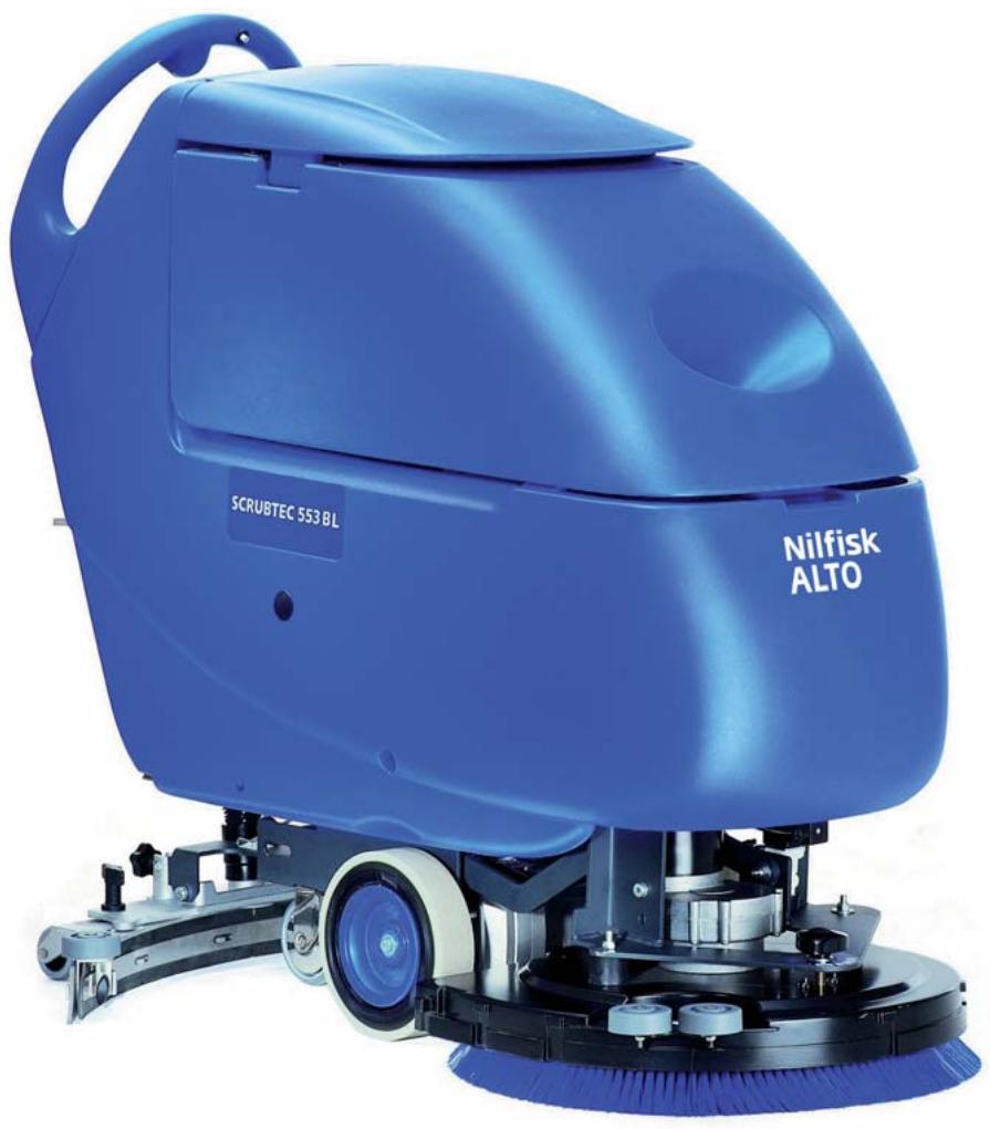
MACHINE DESCRIPTION
MACHINE STRUCTURE
- Control panel
- Handlebar
- Brush/forward gear switch () Brush switch (^*)
- Drive speed adjuster (*)
- Battery charger data inspection window (optional)
- Battery charger cable (optional)
- Battery charger cable holder (optional)
- Recovery water drain hose plug
- Reverse gear switch
- Squeegee lifting/lowering lever
- Deck lifting/lowering pedal
11a. Pedal position when deck is lifted
11b. Pedal position when deck is lowered
11c. Extra pressure activation (optional)
- Battery connector (red) (this connector also works as EMERGENCY push-button, to stop immediately all functions)
- Rear steering wheels
- Front wheels on fixed axle. Driving wheels (^*)
- Squeegee vacuum hose
- Recovery water drain hose
- Solution/clean water drain and level check hose
- Brush/pad-holder deck
- Brush/pad-holder
- Solution/clean water tank
- Recovery tank
- Recovery tank cover
- Can holder
- Solenoid valve
- Squeegee
- Squeegee mounting handwheels
-
Squeegee adjusting handwheel
-
Machine straight forward movement adjusting handwheel
- Machine forward speed adjusting handwheel (^**)
- Recovery water tank cover (opened)
- Tank cover gasket
- Cover movable retaining plate
- Cover fixed retaining plate (do not remove!)
- Serial number plate/technical data/conformity certification
- Squeegee bumper wheels
- Vacuum grid with automatic shut-off float
- Solution filler neck
- Filter
- Deck bumper wheels
- Recovery water tank (opened)
- Detergent/clean water hose
- Tank safety cable
- Vacuum system motor cover
- Vacuum system motor sound-deadening filter
- Detergent tank (^**)
- Detergent tank plug (^**)
- Detergent tank handle (^**)
- Detergent feed hose (^**)
- Detergent pump (^**)
- Detergent tank - pump connecting hose (^**)
- Solution/clean water filter
- Solution/clean water tap
- Batteries
- Battery caps
- Reference table for detergent proportioning (^**)
- Battery connection diagram
- BOOST 5 deck
- BOOST 5 deck pad
() Only for SCRUBTEC 545BL, 553BL e BOOST 5
(^) Only for machines with Chemical Mixing System (optional)
(**) Only for SCRUBTEC 545B and 553B
P100101
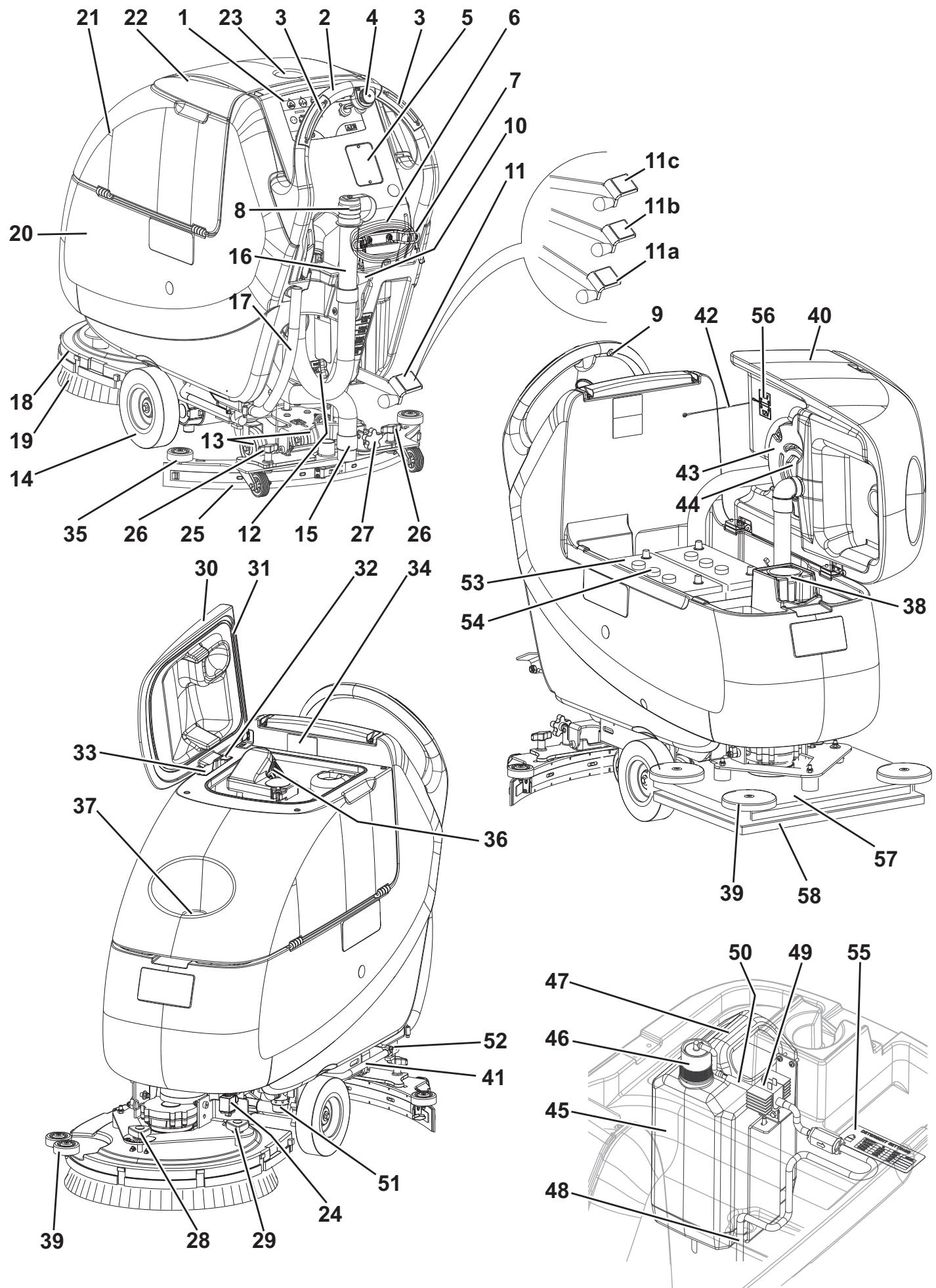
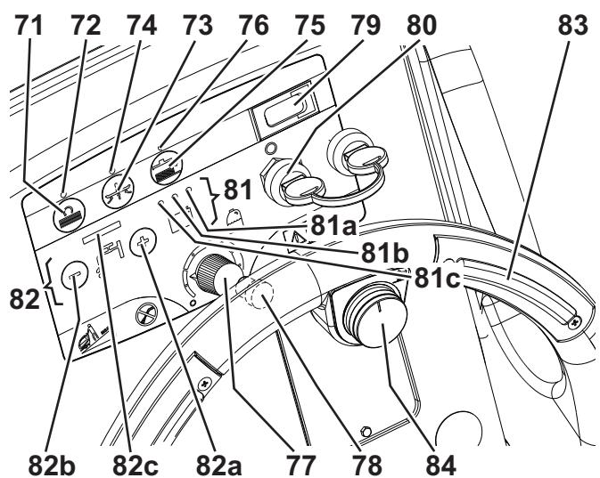
CONTROL PANEL
- Brush/pad-holder switch
- Brush/pad-holder switch warning light
- Vacuum system switch
- Vacuum system switch warning light
- Brush/pad-holder release switch
- Brush/pad-holder release switch warning light
- Detergent flow control knob (^**)
- Reverse gear switch (*)
- Hour counter (optional)
- Ignition key (0 - 1)
- Battery charge indicator
81a. Charged battery warning light (green)
81b. Semi-discharged battery warning light (yellow)
81c. Discharged battery warning light (red)
82. Washing water flow control switches
82a. Flow increase switch
82b. Flow decrease switch
82c. Washing water flow indicator
83. Brush/forward gear switch (). Brush switch (*)
84. Speed adjuster ()
() Only for SCRUBTEC 545BL, 553BL e BOOST 5
() Only for machines with Chemical Mixing System (optional)
(^*) Only for SCRUBTEC 545B and 553B
SCRUBTEC 545B - 553B
P100102
SCRUBTEC 545BL - 553BL - BOOST 5
P100103
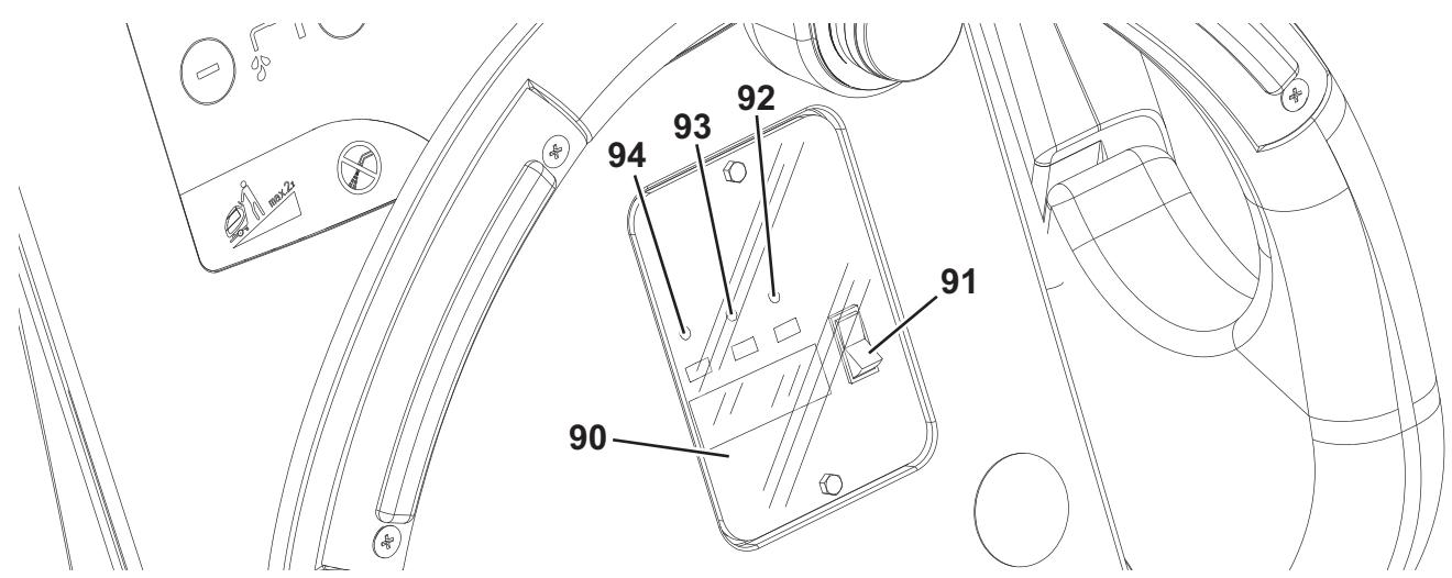
BATTERY CHARGER DATA INSPECTION WINDOW (optional)
- Electronic battery charger
- Lead (WET) or gel (GEL) battery selector
-
Green warning light (the battery charger is on and batteries are charged)
-
Yellow warning light (the battery charger is on and batteries are semi-discharged)
- Red warning light (the battery charger is on and it is charging the batteries)
P100104
ACCESSORIES/OPTIONS
In addition to the standard components, the machine can be equipped with the following accessories/options, according to the machine specific use:
- GEL batteries
- Electronic battery charger
- Brushes of different materials
- Pads of different materials
- Polyurethane squeegee blades
- Chemical Mixing System
- Front and rear wheels of different materials
- Hour counter
For further information concerning the optional accessories, contact an authorised Retailer.
TECHNICAL DATA
| Model | SCRUBTEC 545B
1 brush/pad-hold-
er, without drive system | SCRUBTEC 545BL
1 brush/pad-
holder, with drive system | SCRUBTEC 553B
1 brush/pad-hold-
er, without drive system | SCRUBTEC 553BL
1 brush/pad-
holder, with drive system | SCRUBTEC BOOST 5
Vibrating deck,
with drive system |
| Machine height | 1,058.5 mm |
| Solution/clean water tank capacity | 42 litres |
| Recovery tank capacity | 42 litres |
| Front wheel diameter | 200 mm |
| Front and rear wheel specific pressure on the floor | 0.9 N/mm² - 3 N/mm² |
| Rear wheel diameter | 100 mm |
| Vacuum system motor power | 330 W |
| Drive system motor power | — | 200 W | — | 200 W |
| Drive speed (variable) | — | 0 to 4.5 km/h | — | 0 to 4.5 km/h |
| Gradeability | 2 % |
| Sound pressure level at workstation (ISO 11201, ISO 4871) (LpA) | 65.8 dB(A) ± 3 dB(A) |
| Machine sound pressure level (ISO 3744, ISO 4871) (LwA) | 84 dB(A) |
| Vibration level at the operator's arms (ISO 5349-1) | < 2.5 m/s² |
| Standard batteries | (2 x 12 V) 95 - 165 Ah @ 20 h |
| Battery compartment size (width x length x height) | 350 x 350 x 300 mm |
| Vacuum system circuit capacity | 1,055 mm H₂O |
| Cleaning width | 450 mm | 530 mm | 510 mm |
| Squeezegee width | 760 mm |
| Machine maximum length | 1,190 mm | 1,228 mm |
| Machine width without squeezegee | 512 mm | 540.8 mm |
| Brush diameter | 450 mm | 530 mm |
| BOOST® brush size | — | — | 355 x 508 mm |
| Weight without batteries and with empty tanks | 81 kg | 96 kg | 81 kg | 96 kg | 92 kg |
| Maximum weight with batteries and full tanks | 213 kg | 229 kg | 213 kg | 229 kg | 182 kg |
| Brush motor power | 480 W | 560 W |
| Brush speed | 153 rpm | 2,250 rpm |
| Brush/pad-holder pressure with extra-pressure function turned off | 19.0 kg | 20.5 kg | 18 kg |
| Brush/pad-holder pressure with extra-pressure function turned on | Optional | 29 kg | Optional | 30 kg | 34 kg |
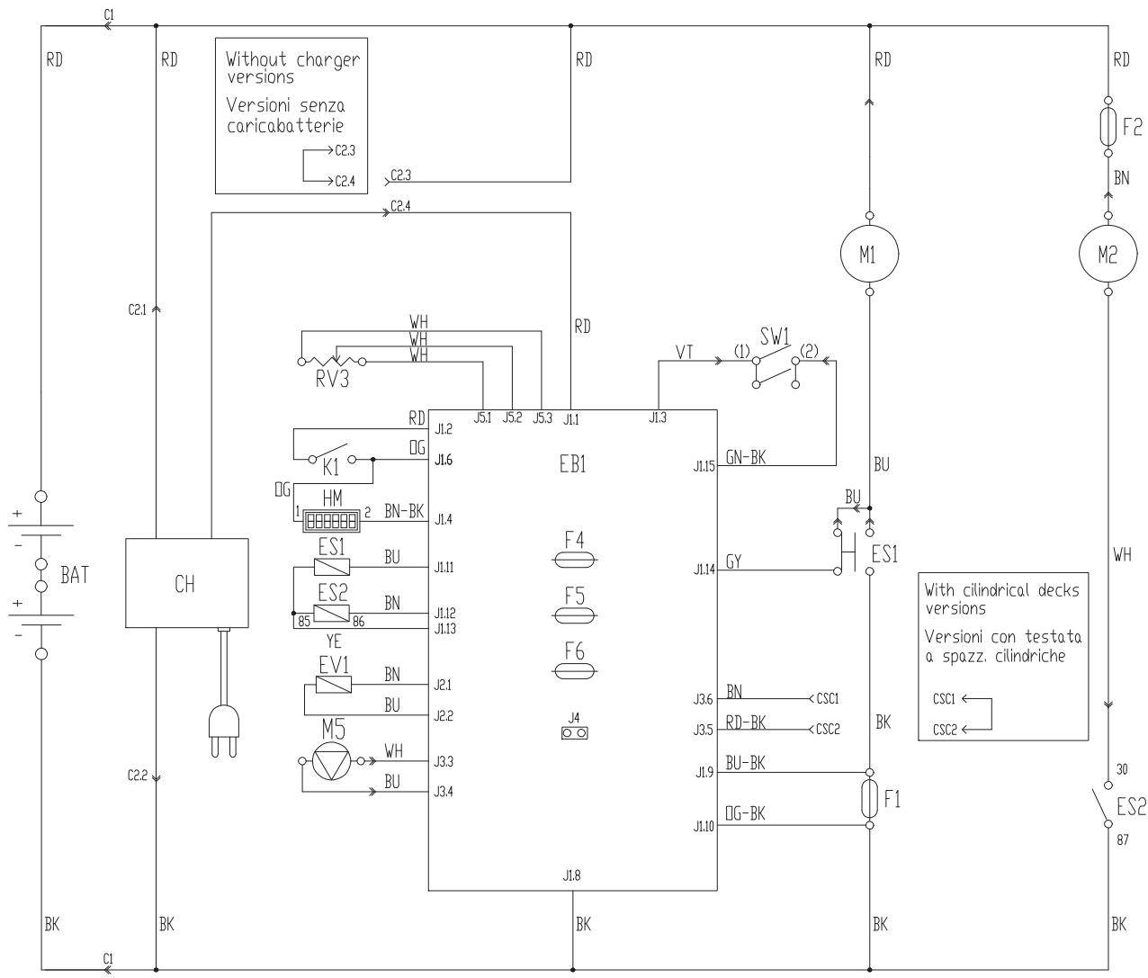
WIRING DIAGRAM (SCRUBTEC 545B - 553B)
Key
| BAT | 24 V battery |
| C1 | Battery connector |
| C2 | Battery charger connector |
| CH | Battery charger (optional) |
| CS | Deck connector |
| EB1 | Function electronic board |
| ES1 | Brush electromagnetic switches |
| ES2 | Vacuum system relay |
| EV1 | Water solenoid valve |
| F1 | Deck fuse |
| F2 | Vacuum system fuse |
| F4 | Signal circuit fuse |
| F5 | Brush release fuse |
| F6 | Pump fuse |
| HM | Hour counter (optional) |
| K1 | Ignition key |
| M1 | Brush/pad-holder motor |
| M2 | Vacuum system motor |
| M5 | Detergent pump (optional) |
| RV3 | Detergent % potentiometer (optional) |
| SW1 | Brush/drive system enabling switch |
Colour codes
| BK | Black |
| BU | Blue |
| BN | Brown |
| GN | Green |
| GY | Grey |
| OG | Orange |
| PK | Pink |
| RD | Red |
| VT | Violet |
| WH | White |
| YE | Yellow |
P100127
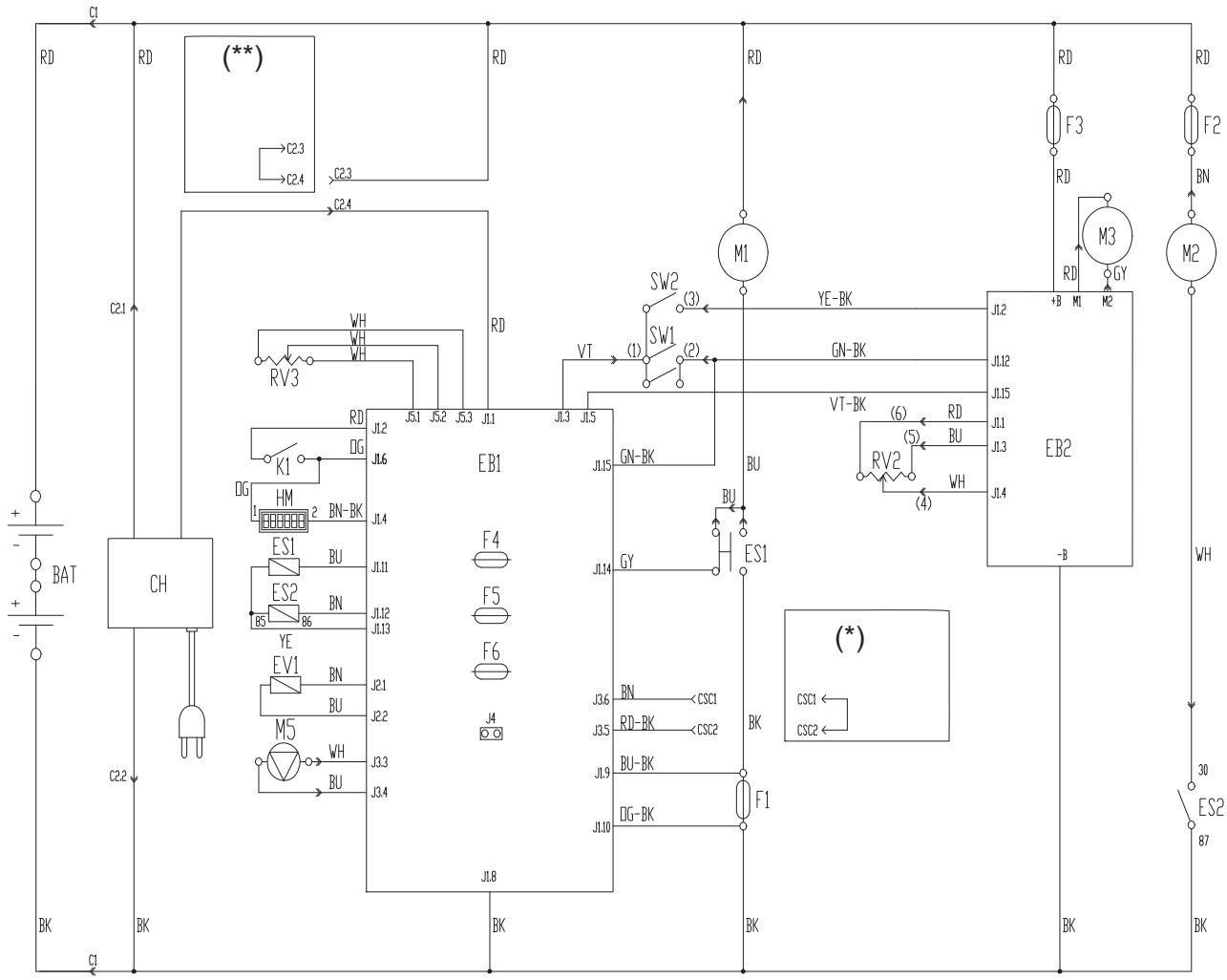
WIRING DIAGRAM (SCRUBTEC 545BL - 553BL - BOOST 5)
Key
| BAT | 24 V battery |
| C1 | Battery connector |
| C2 | Battery charger connector |
| CH | Battery charger (optional) |
| EB1 | Function electronic board |
| EB2 | Drive system electronic board |
| ES1 | Brush electromagnetic switches |
| ES2 | Vacuum system relay |
| EV1 | Detergent solenoid valve (optional) |
| F1 | Deck fuse |
| F2 | Vacuum system fuse |
| F3 | Drive system fuse |
| F4 | Signal circuit fuse |
| F5 | Brush/pad-holder release fuse |
| F6 | Pump fuse |
| HM | Hour counter (optional) |
| K1 | Ignition key |
| M1 | Brush/pad-holder motor |
| M2 | Vacuum system motor |
| M3 | Drive system motor |
| M5 | Detergent pump (optional) |
| RV2 | Maximum speed potentiometer |
| RV3 | Detergent % potentiometer (optional) |
| SW1 | Brush/drive system enabling switch |
| SW2 | Reverse gear switch |
Colour codes
| BK | Black |
| BU | Blue |
| BN | Brown |
| GN | Green |
| GY | Grey |
| OG | Orange |
| PK | Pink |
| RD | Red |
| VT | Violet |
| WH | White |
| YE | Yellow |
(^**) Only for machines without on-board battery charger
P100128
USE

WARNING!
On some points of the machine there are some adhesive plates indicating:
DANGER
WARNING
- CAUTION
CONSULTATION
While reading this Manual, the operator must pay particular attention to the symbols shown on the plates.
Do not cover these plates for any reason and immediately replace them if damaged.
BATTERY CHECK/SETTING ON A NEW MACHINE

WARNING!
The electric components of the machine can be seriously damaged if the batteries are either improperly installed or connected. The batteries must be installed by qualified personnel only. Set the function electronic board and the battery charger (optional) according to the type of batteries used (WET or GEL).
Check the batteries for damage before installation.
Disconnect the battery connector and the battery charger plug.
Handle the batteries with great care.
Install the battery terminal protection caps supplied with the machine.
The machine requires two 12 V batteries, connected according to the diagram (56).
The machine can be supplied in one of the following modes:
A) Batteries (WET or GEL) already installed and ready to be used
- Check that the batteries are connected to the machine with the connector (12).
- Insert the ignition key (80) and turn it to "I".
If the green warning light (81a) turns on, the batteries are ready to be used.
If the yellow or red warning light (81b or 81c) turns on, the batteries must be charged (see the procedure in Maintenance chapter).
B) Batteries (WET) installed on the machine, but without electrolyte
- Open the cover (22) and check that the recovery tank (21) is empty, otherwise empty it with the drain hose (16).
- Carefully lift the tank (40).
- Remove the caps (54) of the batteries (53).

WARNING!
Pay attention when using sulphuric acid, as it is corrosive. If it comes in contact with skin or eyes, rinse thoroughly with water and consult a physician.
Batteries have to be filled in a well-ventilated area. Wear protective gloves.
- Fill up the battery cells with sulphuric acid for batteries (density 1.27 to 1.29kg at 25^ ) in accordance with the instructions shown in the Battery Manual. The correct quantity of sulphuric acid is shown in the Battery Manual.
- To avoid damaging the floor, dry with a cloth both acid and water on the top of the batteries after charging.
- Let the batteries rest and fill in with sulphuric acid as shown in the Battery Manual.
- Charge the batteries (see the procedure in Maintenance chapter).
C) Without batteries
- Buy appropriate batteries (see Technical Data paragraph).
- For battery choice and installation, apply to qualified battery Retailers.
- Set the machine and the battery charger (if equipped) according to the type of batteries installed (WET or GEL) as shown in the following paragraph.
BATTERY INSTALLATION AND BATTERY TYPE SETTING (WET OR GEL)
Set the electronic board of the machine and of the battery charger (if equipped) according to the type of batteries installed (WET or GEL) according to the following procedure:
Machine setting
- Turn the ignition key (80) to "I" and pay attention to the following in the very first seconds of machine operation:
If the green warning light (81a) is flashing, the machine is set to GEL.
If the red warning light (81c) is flashing, the machine is set to WET.
- If the setting is to be changed, perform the following procedure.
- Turn off the machine by turning the ignition key (80) to "0".
- Press and hold the switches (71) and (73) at the same time, then turn the ignition key (80) to "I".
- Release the switches (71) and (73) at least 8 seconds after starting the machine.
- Within 3 seconds, press the switch (73) again for a few seconds and check that the warning light for the required setting is flashing (as shown in step 1).
Battery charger setting (for machines with on-board battery charger)
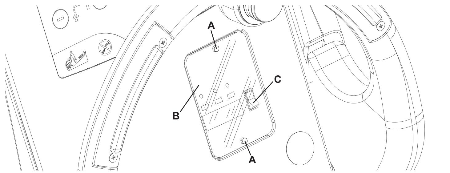
- Remove the battery charger data inspection window screws (A, Fig. 1).
- Remove the window (B).
- Turn the battery charger selector (C) to WET position for lead batteries, or to GEL position for gel batteries.
- Install the window (B) and tighten the screws (A).
Battery installation
- Open the cover (22) and check that the recovery tank (21) is empty, otherwise empty it with the drain hose (16).
- Carefully lift the tank (40).
- Install the batteries.
Battery charging
- Charge the batteries (see the procedure in Maintenance chapter).
P100105
Figure 1
BEFORE MACHINE START-UP
Brush/pad-holder installation/removal (for SCRUBTEC 545B - 545BL - 553B - 553BL)
- According to the kind of cleaning to be performed, the machine can be equipped either with the brush (A, Fig. 2) or the pad-holder (B) with pad (C) together with the appropriate deck.
- Insert the ignition key (80) and turn it to "I".
- If equipped, turn the speed adjuster (84) to idle by turning it counter-clockwise.
- Place the brush (A) or the pad-holder (B) under the deck (18).
- Lower the deck on the brush/pad-holder by pressing the pedal (11).
- Turn the ignition key (80) to "I".
- Press the brush/pad-holder switch (71).
- Press one of the switches (83) to engage the brush/pad-holder, then release it. If necessary, repeat the procedure until the brushes/pad-holders are engaged.
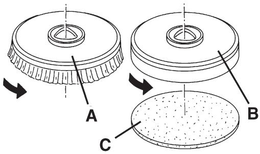
Figure 2
S311334

WARNING!
(Only for SCRUBTEC 545BL and 553BL): Turn the speed adjuster (84) counter-clockwise to drive the machine at the minimum speed.
To engage the brush/pad-holder press the switch (83) which turns on the brush/pad-holder motor.
- To remove the brush/pad-holder, the deck must be lifted by pressing the pedal (11), then press the switch (75) and wait for the brush/pad-holder to fall on the floor.
Turn the ignition key (80) to "0".
Types of brushes available (for SCRUBTEC 545B - 545BL - 553B - 553BL)
| 450 mm-models |
| PROLENE |
| MIDLITE GRIT 180 |
| MIDGRIT 240 |
| PROLITE |
| UNION MIX |
| 530 mm-models |
| PROLENE |
| MIDLITE GRIT 180 |
| MIDGRIT 240 |
| PROLITE |
| UNION MIX |
Brush/pad application guide (for SCRUBTEC 545B - 545BL - 553B - 553BL) (suggestions only)
| Models | MIDLITE GRIT 180 | MIDGRIT 240 | PROLENE | PROLITE | UNION MIX |
| General cleaning: |
| Concrete | | | | | |
| Terrazzo floor | | | | | |
| Ceramic tiles/quarrystones | | | | | |
| Marble | | | | | |
| Vinyl tiles | | | | | |
| Rubber tiles | | | | | |
| Polishing: |
| Rubber tiles | | | | | |
| Marble | | | | | |
| Vinyl tiles | | | | | |
Brush/pad-holder installation/removal (for SCRUBTEC BOOST 5)
- The machine can be equipped with pads (58) according to the type of floor to be cleaned.
- Turn the ignition key (80) to "0".
- Lift the deck (57) by pressing the pedal (11).
- Install the pads (58) so that it engages the Boost deck.
- To remove the pad, perform steps 2 to 4 in the reverse order.
Types of brushes available (for BOOST 5)
| Pads |
| RED PADS (5 PIECES) |
| BLACK PADS (5 PIECES) |
| WHITE PADS (5 PIECES) |
| BLUE PADS (5 PIECES) |
| MAROON PADS (10 PIECES) |
| Brushes |
| POLY BRUSH |
| NYLON BRUSH |
| GRIT BRUSH |
Cylindrical brush application guide (for SCRUBTEC BOOST 5) (suggestions only)
| Models | POLYPROPYLENE | NYLON | CLEAN GRIT |
| Concrete | | | |
| Terrazzo floor | | | |
| Ceramic tiles/quarrystones | | | |
| Marble | | | |
| Vinyl tiles | | | |
| Rubber tiles | | | |
Squeegee installation
- Install the squeegee (25) and fasten it with the handwheels (26), then connect the vacuum hose (15) to the squeegee.
- Adjust the squeegee with the handwheel (27) so that the rear blade - in all its length - touches the floor.
Solution or washing water tank filling

NOTE
If the machine is equipped with Chemical Mixing System (adjusting knob (77) (optional)) the tank must be filled with clean water, otherwise the tank must be filled with solution.
1. (For machines without Chemical Mixing System)
Use the filler neck (37) to fill the tank (20) with a solution suitable for the work to be performed.
Do not fill the solution tank completely, leave a few centimetres from the edge. Use the removable hose (17) as reference.
Always follow the dilution instructions on the label of the chemical product used to prepare the solution.
The solution temperature must not exceed 40^ .

WARNING!
Use only low-foam and non-flammable detergents, intended for automatic scrubber applications.
(For machines with Chemical Mixing System)
Fill the tank (20) with clean water by using the filler neck (37).
Do not fill the clean water tank completely, leave a few centimetres from the edge.
The water temperature must not exceed 40^ .
Detergent tank filling (For machines with Chemical Mixing System)
- Open the cover (22) and check that the recovery tank (21) is empty, otherwise empty it with the drain hose (16).
- Carefully lift the tank (40).
- Open the plug (46).
- Fill the tank (45) with a detergent suitable for the work to be performed (highly concentrated detergent).
- Do not fill the detergent tank completely, leave a few inches from the edge.

CAUTION!
Use only low-foam and non-flammable detergents, intended for automatic scrubber applications.

NOTE
In case of new system, system emptied for cleaning, etc., wait for the hoses to fill up, before starting the Chemical Mixing System.
MACHINE START AND STOP
Starting the machine
-
Prepare the machine as shown in the previous paragraph.
-
Insert the ignition key (80) and turn it to "I". Check that the green warning light (81a) turns on (charged batteries). If the yellow or red warning light (81b or 81c) turns on, turn the ignition key back to "0" and charge the batteries (see the procedure in Maintenance chapter).
-
Drive the machine to the working place:
-
By pushing it with the hands on the handlebar (2) (only for SCRUBTEC 545B and 553B).
- By pushing it with the hands on the handlebar (2) and pressing the switch (83) to move forward, or pressing the switch (83) together with the switch (78) to move rearward (only for SCRUBTEC 545BL, 553BL and BOOST 5).
The forward speed can be adjusted with the adjuster (84).
- Lower the squeegee (25) with the lever (10).
- Lower the brush/pad-holder deck by pressing the pedal (11).
- Press the brush/pad-holder and vacuum system switch (71).
- Press the washing water flow control switches (82) as necessary, depending on the type of cleaning to be performed.
- Start cleaning, by moving the machine as shown in step 3. If necessary, adjust the maximum speed with the adjuster (84).
- If it is necessary to use the vacuum system only, stop the brush/pad-holder and the vacuum system with the switch (71), and press the vacuum system switch (73).

NOTE
To move the machine forward, press either the left or right switch (83) or both.
Stopping the machine
- Stop the machine with the handlebar (2) (only for SCRUBTEC 545B and 553B).
Stop the machine by releasing the switches (83) (only for SCRUBTEC 545BL, 553BL and BOOST 5).
- Turn off the brush/pad-holder and the vacuum system with the switch (71).
- Lift the brush/pad-holder deck by pressing the pedal (11).
- Lift the squeegee (25) with the lever (10).
- Make sure that the machine cannot move independently.
MACHINE OPERATION (SCRUBBING/DRYING)
- Start the machine as shown in the previous paragraph.
- If necessary, press the washing water flow control switches (82) as necessary, depending on the type of cleaning to be performed.
- If necessary, stop the machine and turn the squeegee adjusting handwheel (27) so that the rear blade - in all its length - touches the floor.
- If necessary, stop the machine and turn the adjusting handwheel (28); when turning it clockwise or counter-clockwise the machine forward speed can be adjusted.
-
If necessary, stop the machine and turn the machine forward speed adjusting handwheel (29) (only for SCRUBTEC 545B and 553B) as shown below:
-
Turn it counter-clockwise to increase the forward speed;
- Turn it clockwise to decrease the forward speed.

NOTE
For correct scrubbing/drying of floors at the sides of the walls, Nilfisk Alto suggests to go near the walls with the right side of the machine as shown in figure 3.
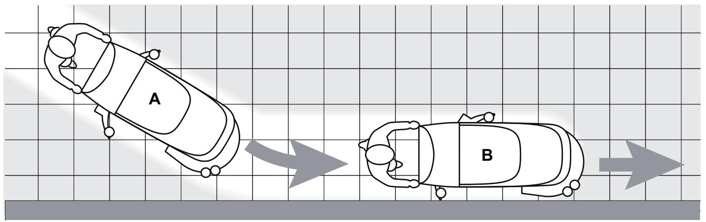
P100106A

Figure 3
CAUTION!
To avoid any damage to the floor surface, turn off the brush/pad-holder when the machine stops in one place, especially when the extra pressure function is on.
Detergent flow adjustment
(For machines with Chemical Mixing System)
- Turn the knob (A, Fig. 4) clockwise or counter-clockwise to increase or decrease the detergent concentration.
- The average detergent concentration values, matching the 4 coloured areas of the scale (B), are shown in the figure.
- To set the detergent quantity to zero, fully turn the knob (A) counter-clockwise.

NOTE
The detergent concentration is kept constant even if the washing water flow is changed with the switches (C) or (D).
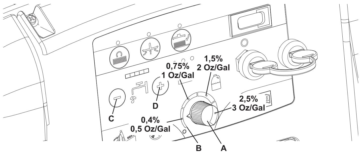
Figure 4
P100107
If the floor proves to be particularly difficult to clean, it is possible to turn on the brush/pad-holder extra pressure function by pressing the pedal (11) to position (11c).

CAUTION!
In case of brush/pad-holder motor overload, due to foreign bodies which prevent them from turning, or to excessively aggressive floors/brushes, the safety system stops the brush/pad-holder after about one minute of continuous overload.
The overload is shown by the three warning lights (81a, 81b, 81c) flashing simultaneously.
If the overload takes place when the extra pressure function (11c) is on, the pedal position must be changed to (11b). If the overload persists, the brush/pad-holder stops.
To start scrubbing again after a brush/pad-holder stop due to overload, stop the machine by turning the ignition key (80) to "0". Turn on the machine by turning the ignition key (80) to "1".
Battery discharge during operation
Until the green warning light (81a) stays on, the batteries allow the machine to work normally.
When the green warning light (81a) turns off, and the yellow warning light (81b) turns on, it is advisable to charge the batteries, because the residual autonomy will last for a few minutes (depending on battery characteristics and work to be performed).
When the red warning light (81c) turns on, the autonomy is over. After a few seconds, the brush/pad-holder is automatically tuned off, while the vacuum system and (only for SCRUBTEC 545BL, 553BL and BOOST 5) the drive system stay on, to finish drying the floor and drive the machine to the appointed recharging area.

CAUTION!
Do not use the machine with discharged batteries, to avoid damaging the batteries and reducing the battery life.
TANK EMPTYING
An automatic float shut-off system (36) turns off the vacuum system when the recovery tank (21) is full.
The vacuum system deactivation is signalled by a sudden increase in the vacuum system motor noise frequency, and the floor is not dried.

CAUTION!
If the vacuum system turns off accidentally (for example, when the float is activated because of a sudden machine movement), to resume the operation: turn off the vacuum system by pressing the switch (73), then open the cover (22) and check that the float inside the grid (36) has gone down to the water level. Then close the cover (22) and turn on the vacuum system by pressing the switch (73).
When the recovery tank (21) is full, empty it according to the following procedure.
Recovery tank emptying
- Stop the machine.
- Lift the brush/pad-holder deck by pressing the pedal (11).
- Lift the squeegee (25) with the lever (10).
- Drive the machine to the appointed disposal area.
- Empty the recovery tank with the hose (16). Then, rinse the tank with clean water.
Solution/clean water tank emptying
- Perform steps 1 to 4.
- Empty the solution tank with the hose (17). Then, rinse the tank with clean water.
AFTER USING THE MACHINE
After working, before leaving the machine:
- Remove the brush/pad-holder as shown in the relevant paragraph.
- Empty the tanks (20 and 21) as shown in the relevant paragraphs.
- Perform the daily maintenance procedures (see the Maintenance chapter).
- Store the machine in a clean and dry place, with the brush/pad-holder and the squeegee lifted or removed.
MACHINE LONG INACTIVITY
If the machine is not going to be used for more than 30 days, proceed as follows:
- Perform the procedures shown in After Using the Machine paragraph.
- Disconnect the battery connector (12).
FIRST PERIOD OF USE
After the first 8 hours, check the machine fastening and connecting parts for proper tightening and check the visible parts for integrity and leakage.
MAINTENANCE
The lifespan of the machine and its maximum operating safety are ensured by correct and regular maintenance.
The following table provides the scheduled maintenance. The intervals shown may vary according to particular working conditions, which are to be defined by the person in charge of the maintenance.

WARNING!
The procedures must be performed with the machine off and the battery disconnected.
Moreover, read carefully the instructions in Safety chapter before performing any maintenance procedure.
All scheduled or extraordinary maintenance procedures must be performed by qualified personnel, or by an authorised Service Center.
This Manual describes only the easiest and most common maintenance procedures.
For other maintenance procedures shown in the Scheduled Maintenance Table, refer to the Service Manual that can be consulted at any Service Center.
SCHEDULED MAINTENANCE TABLE
| Procedure | Daily, after using the machine | Weekly | Every six months | Yearly |
| Battery charging | | | | |
| Squeegee cleaning | | | | |
| Brush/pad cleaning | | | | |
| Tank and vacuum grid with float cleaning, and cover gasket check | | | | |
| Chemical Mixing System cleaning and draining (optional) | | | | |
| Squeegee blade check and replacement | | | | |
| Solution/clean water filter cleaning | | | | |
| Vacuum system motor filter cleaning | | | | |
| WET battery fluid level check | | | | |
| Screw and nut tightening check | | | (1) | |
| Brush/pad-holder motor carbon brush check or replacement | | | | (2) |
| Vacuum system motor carbon brush check or replacement | | | | (2) |
| Drive system motor carbon brush check or replacement (only for SCRUBTEC 545BL, 553BL and BOOST 5) | | | | (2) |
| Vibration-dampers replacement (only for BOOST 5) | | | | (2) |
(1) And after the first 8 working hours.
(2) This maintenance procedure must be performed by Nilfisk Alto authorised Service Center.
BATTERY CHARGING

NOTE
Charge the batteries when the yellow or red warning light (81b or 81c) turns on, or at the end of every working cycle.

CAUTION!
Keeping the batteries charged make their life last longer.

CAUTION!
When the batteries are discharged, charge them as soon as possible, as that condition makes their life shorter.
Check for battery charge at least once a week.

CAUTION!
If the machine is not equipped with on-board battery charger, choose an external battery charger suitable for the type of batteries installed.

CAUTION!
WET battery charging produces highly explosive hydrogen gas. Charge the batteries in well-ventilated areas and away from naked flames. Do not smoke while charging the batteries.
Keep the tank assembly open while charging the batteries.

WARNING!
Pay careful attention when charging the batteries as there may be battery fluid leakages. The battery fluid is corrosive. If it comes in contact with skin or eyes, rinse thoroughly with water and consult a physician.
Preliminary operations
- Open the cover (22) and check that the recovery tank (21) is empty, otherwise empty it with the drain hose (16).
- Drive the machine to the appointed recharging area.
- Turn the ignition key (80) to "0".
- Carefully lift the tank (40).
-
For WET batteries only:
-
Check the level of electrolyte inside the batteries (53); if necessary, top up through the caps (54).
-
Then leave all the caps (54) open for battery charging.
If necessary, clean the upper surface of the batteries.
-
Charge the batteries according to one of the following procedures, depending on the presence of the battery charger (90).
Charging the batteries with an external battery charger
- Check that the external battery charger is suitable by referring to the relevant Manual. The battery charger voltage rating must be 24V .
- Disconnect the battery connector (12) and connect it to the external battery charger.
- Connect the battery charger to the electrical mains.
- After charging, disconnect the battery charger from the electrical mains and from the battery connector (12).
- (Only for WET batteries)
Check the level of electrolyte inside the batteries and close all the caps (54).
- Connect the battery connector (12) to the machine.
- Carefully lower the tank (40).
Battery charging with (optional) battery charger installed on the machine
- Connect the battery charger cable (6) to the electrical mains (the electrical mains voltage and frequency must be compatible with the battery charger values shown on the machine serial number plate (34)).
When the battery charger is connected to the electrical mains, all machine functions are automatically cut off. If the red warning light (94) on the battery charger control panel stays on, the battery charger is charging the batteries.
- When the green warning light (92) turns on, the battery charging is completed.
- When the battery charging is completed, disconnect the battery charger cable (6) from the electrical mains and wind it round its housing (7).
- Carefully lower the tank (40).

NOTE
For further information about the battery charger (90) operation, see the relevant Manual.
MACHINE WORKING HOUR CHECK
(Only if the machine is equipped with hour counter)
- Turn the ignition key (80) to "I".
- Press the switch (73) and read on the hour counter (79) the total number of working hours (scrubbing/drying) performed by the machine.
- Press the switch (73) again.
- Turn the ignition key (80) to "0".
SQUEEGEE CLEANING

NOTE
The squeegee must be clean and its blades must be in good conditions in order to get a good drying.

CAUTION!
It is advisable to wear protective gloves when cleaning the squeegee because there may be sharp debris.
- Drive the machine on a level floor.
- Turn the ignition key (80) to "0".
- Lower the squeegee (25) with the lever (10).
- Loosen the handwheels (26) and remove the squeegee (25).
- Disconnect the vacuum hose (15) from the squeegee.
- Wash and clean the squeegee (Fig. 4). In particular, clean the compartments (A, Fig. 4) and the vacuum hole (B) from dirt and debris. Check the front blade (C) and the rear blade (D) for integrity, cuts and tears; if necessary replace them (see the procedure in the following paragraph).
- Install the squeegee in the reverse order of removal.
SQUEEGEE BLADE CHECK AND REPLACEMENT
-
Clean the squeegee (Fig. 5) as shown in the previous paragraph.
-
Check that the edge (E, Fig. 5) of the front blade (C) and the edge (F) of the rear blade (D) lay down on the same level, along their length; otherwise adjust their height according to the following procedure:
-
Remove the tie rod (G), disengage the retainers (M) and adjust the rear blade (D); then engage the retainers and install the tie rod.
-
Loosen the handwheels (I) and adjust the front blade (C); then tighten the handwheels.
-
Check the front blade (C) and rear blade (D) for integrity, cuts and tears; if necessary replace them as shown below. Check that the front corner (J) of the rear blade is not worn; otherwise, overturn the blade to replace the worn corner with an integral one. If the other corners are worn too, replace the blade according to the following procedure:
-
Remove the tie rod (G), disengage the fasteners (M) and remove the retaining strip (K), then replace/overturn the rear blade (D). Install the blade in the reverse order of removal.
- Unscrew the handwheels (I) and remove the retaining strip (L), then replace the front blade (C). Install the blade in the reverse order of removal.
After the blade replacement (or overturning), adjust the height as shown in the previous step.
- Connect the vacuum hose (15) to the squeegee.
- Install the squeegee (25) and screw down the handwheels (26).
- If necessary, adjust the squeegee adjusting handwheel (27).
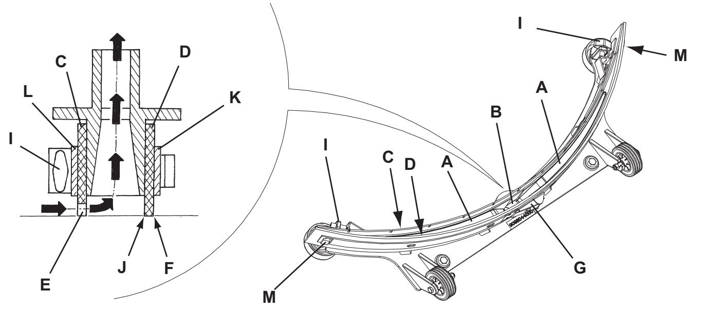
Figure 5
S311336
BRUSH/PAD CLEANING

CAUTION!
It is advisable to wear protective gloves when cleaning the brush/pad because there may be sharp debris.
- Remove the brush/pad from the machine, as shown in Use chapter.
- Clean and wash the brush/pad with water and detergent.
- Check the brush bristles for integrity and wear; if necessary, replace the brush.
- Check the pad for wear; if necessary, replace the pad.
TANK AND VACUUM GRID WITH FLOAT CLEANING, AND COVER GASKET CHECK
- Drive the machine to the appointed disposal area.
- Turn the ignition key (80) to "0".
- Open the cover (A, Fig. 6) to washing position (L).
- Wash with clean water the cover (A), the tanks (B and C) and the vacuum grid with automatic shut-off float (D). Drain the water from the tanks with the hoses (16 and 17).
- If necessary, release the fasteners (E) and open the grid (D), recover the float (F), clean all the components and then reinstall them.
- Check the tank cover gasket (G) for integrity.

NOTE
The gasket (G) creates vacuum in the tank that is necessary for vacuuming the recovery water.
If necessary replace the gasket (G) by removing it from its housing (H). When assembling the new gasket, install the joint (I) in the rear central area, as shown in the figure.
- Check that the seating surface (J) of the gasket (G) is integral and adequate for the gasket itself.

NOTE
The hole (K), allowing to compensate the air in the cover air gap, contributes to create vacuum in the tank.
- Close the cover (A).

P100108
Figure 6
VACUUM SYSTEM MOTOR FILTER CLEANING
- Drive the machine on a level floor.
- Turn the ignition key (80) to "0".
- Open the recovery water tank.
- If necessary, drain the water from the tank in order to make the filter visible.
- Check that the pre-filter is clean. If necessary clean it with water and compressed air, then install it.
- Perform steps 1, 2 and 3 in the reverse order.
SOLUTION/CLEAN WATER FILTER CLEANING
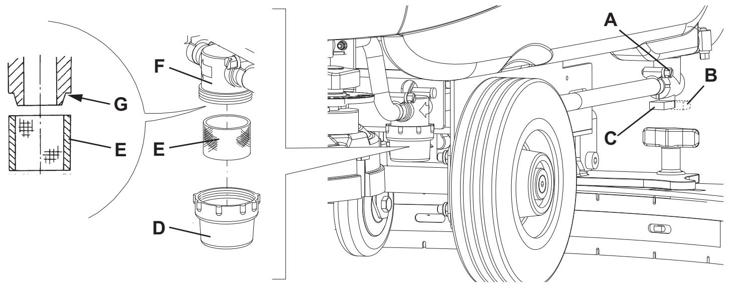
- Drive the machine on a level floor.
- Turn the ignition key (80) to "0".
- Close the solution tap (A, Fig. 7) under the machine, behind the right rear wheel. The tap (A) is closed when it is in the position (B) and it is open when it is in the position (C).
- Remove the transparent cover (D), then remove the filter strainer (E). Clean and install them on the support (F).

NOTE
The filter strainer (E) must be correctly positioned on the housing (G) of the support (F) .
- Open the tap (A).
Figure 7
P100109
FUSE CHECK/REPLACEMENT
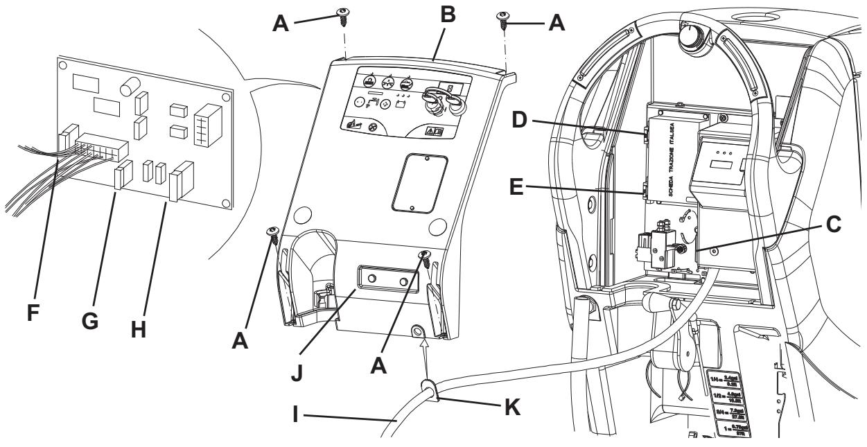
- Disconnect the battery connector (12).
- Move aside the recovery water drain hose (16).
- Remove the battery charger cable (I, Fig. 8), if equipped, from the cable holder (J).
- Remove the screws (A) and carefully move aside the panel (B) by disengaging the grommet (K) from its housing on the panel (B).
- Check/replace the following fuses:
C) Brush deck fuse F1: (40 A)
D) Vacuum system fuse F2: (30 A)
E) Drive system fuse F3: (30 A) ()
F) Signal circuits fuse F4: (3 A)
G) Brush/pad-holder release fuse F5: (20 A)
H) Pump fuse F6: (3 A)
() Only for SCRUBTEC 545BL, 553BL e BOOST 5
- Perform steps 1 to 4 in the reverse order.
Figure 8
P100110
DETERGENT TANK CLEANING
(For machines with Chemical Mixing System)
Clean the detergent tank (45) according to the following procedure:
- Drive the machine to the appointed disposal area.
- Open the cover (22) and check that the recovery tank (21) is empty, otherwise empty it with the drain hose (16). Close the cover (22).
- Carefully lift the tank (40).
- Unscrew the plug (46) and disconnect the hose (50) from the tank (45).
- Remove the tank.
- Wash the tank in the appointed disposal area.
- Install the tank (45) and connect it to the hose (50).
- After draining the detergent tank, drain the Chemical Mixing System too by running the system with clean water only.

NOTE
Drain the Chemical Mixing System when it is dirty/clogged and after long inactivity/uncleaning of the machine.
TROUBLESHOOTING
| Trouble | Possible Cause | Remedy |
| The motors do not operate: no warning light turns on | The battery connector (12) is disconnected. | Connect. |
| The batteries are completely discharged. | Charge the batteries. |
| The machine does not move.
(Only for SCRUBTEC 545BL, 553BL e BOOST 5) | The machine has been turned on by using the ignition key (80) and by keeping the switches (83) pressed. | Turn the ignition key (80) to “0”, then try to start the machine again without pressing the switches (83). |
| The warning lights (81) flash simultaneously. | The brush deck motor is overloaded. | Use a less aggressive brush suitable for the floor to be cleaned or avoid working with extra pressure function turned on. |
| The brush does not work, the red warning light (81c) is on. | The batteries are discharged. | Charge the batteries. |
| The recovery water vacuuming is insufficient. | The recovery water tank (21) is full. | Empty the tank. |
| The hose (15) is disconnected from the squeezegee. | Connect. |
| The vacuum grid (36) is clogged or the float is stuck closed. | Clean the grid or check the float. |
| The squeezegee (25) is dirty or the squeezegee blades are worn or damaged. | Clean and check the squeezegee. |
| The tank cover is not properly closed or the gasket (31) is damaged. | Close the cover or clean/replace the gasket. |
| The solution flow to the brush is insufficient. | The solution/clean water filter (51) is dirty. | Clean the filter. |
| The tank is dirty (the drain hole is clogged). | Clean. |
| The Chemical Mixing System tank (optional) is dirty/clogged. | Clean with the drain cycle. |
| The squeezegee leaves marks on the floor. | There are debris under the squeezegee blades. | Remove the debris. |
| The squeezegee blades are worn, chipped or torn. | Replace the blades. |
| The squeezegee has not been adjusted with the handwheel (27). | Adjust. |

NOTE
If the machine has an optional battery charger installed, the machine cannot operate if the charger is not on board. In case of battery charger malfunction, contact an authorised Service Center.
For further information refer to the Service Manual, available at any Nilfisk Alto Service Center.
SCRAPPING
Have the machine scrapped by a qualified scrapper.
Before scrapping the machine, remove and separate the following materials, which must be disposed of properly according to the Law in force:
Batteries
Brushes/pads
- Plastic hoses and components
- Electrical and electronic components (*)
(*) Refer to the nearest Nilfisk Alto Center especially when scrapping electrical and electronic components.
INHOUDSOPGAVE
INLEIDING 2
DOEL EN INHOUD VAN DEZE HANDLEIDING 2
BETREFFENDE PERSONEN 2
OPBERGEN VAN DE HANDLEIDING 2
CONFORMITEITSVERKLARING 2
IDENTIFICATIEGEGEVENS 2
ANDERE GEBRUIKERSHANDLEIDINGEN 2
VERVANGINGSONDERDELEN EN ONDERHOUD 2
MODIFICATIES EN VERBETERINGEN 3
BEDRIJFSCAPACITEIT 3
ALGEMENE OPMERKINGEN 3
VERPAKKING VERWIJDEREN/AFLEVERING 3
VEILIGHEID 3
GEBRUIKTE SYMBOLEN 3
ALGEMENE INSTRUCTIES 4
BESCHRIJVING VAN DE MACHINE 6
OPBOUW VAN DE MACHINE 6
BEDIENINGSPANEEL 8
KLEPJE VOOR HET AFLEZEN VAN DE GEGEVENS VOOR DE ACCULADER (optioneel) 8
ACCESSORIES / OPTIES 9
TECHNISCHE EIGENSCHAPPEN 9
ELEKTRISCHE INSTALLATIE (SCRUBTEC 545B - 553B) 10
ELEKTRISCHE INSTALLATIE (SCRUBTEC 545BL - 553BL - BOOST 5) 11
GEBRUIK 12
CONTROLE / VOORBEREIDINGEN VOOR ACCU'S OP EEN NIEUWE MACHINE 12
DE ACCU'S MONTEREN EN HET TYPE ACCU INSTellen (WET OF GEL) 13
VOOR HET STARTEN VAN DE MACHINE 14
DE MACHINE STARTEN EN STOPPEN 17
MACHINE IN GEBRUIK (WASSEN/DROGEN) 18
DE TANKS LEGEN 20
NA GEBRUIK VAN DE MACHINE 20
LANGE PERIODEVAN STILLSTAND 20
EERSTE GEBRUKSPERIODE 20
ONDERHOUD 21
ONDERHOUDSSCHEMA 21
ACCU'S OPLADEN 22
CONTROLE VAN DE BEDRIJFSUREN VAN DE MACHINE 23
REINIGING VAN DE TREKKER 23
CONTROLE EN VERVANGING VAN DE RUBBERS VAN DE TREKKER 24
REINIGING VAN DE BORSTELS/PADS 24
REINIGING VAN DE TANKS, VAN HET AANZUIGROOSTER MET VLOTTER EN CONTROLE VAN DE PAKKING VAN DE AFDEKKING 25
REINIGING VAN HET FILTER VOOR DE MOTOR VAN HET AANZUIGSYSTEEM 26
REINIGING VAN HET FILTER VAN HET REINIGINGSMIDDEL/SCHOON WATER 26
CONTROLE / VERVANGING VAN DE ZEKERINGEN 27
REINIGING VAN DE TANK MET REINIGINGSMIDDEL 27
STORINGEN LOKALISEREN 28
VERWIJDERING 28
INLEIDING

OPMERKING
Dornveld/Sphere Business Park
Industrie Asse 3, nr 11 - bus 41
1731 Zellik-Asse
Belgium
Tel.: (+32) 02 467 60 50
Fax: (+32) 02 466 61 50
E-mail: info.be@nilfisk-alto.com
AUSTRIA
Nilfisk-Advance GmbH.
Nilfisk-ALTO
Metzgerstrasse 68
Part of the Nilfisk-Advance Group
4080 B Sladeview Crescent, Unit 1
Mississauga, Ontario L5L 5Y5
Canada
Division of Nilfisk-Advance A/S
Industrivej 1
9560 Hadsund
Denmark
Tel.: (+45) 72182100
Fax: (+45) 72182111
Nilfisk-ALTO Food Division
Division of Nilfisk-Advance A/S
Blytaekkervej 2,
9000 Aalborg Denmark
Tel.: (+45) 72 18 21 00
Fax: (+45) 72 18 20 99
E-mail: scanio.techology@nilfisk-alto.dk
www.nilfisk-alto.com
FRANCE
Nilfisk-ALTO
ALTO France SAS
Aeroparc 1
19 rue lcare
67960 Entzheim
France
Tel.: (+33) 388288400
Fax: (+33) 388300500
E-mail: info@nilfisk-alto-fr
www.nilfisk-alto.com
GERMANY
Nilfisk-ALTO
Division of Nilfisk-Advance AG
Division of Nilfisk-Advance BV
Camastraat 9
NL-1322 BB Almere
Tel.: (+31) 365460760
Fax: (+31) 36 5460 761
E-mail: info@nilfisk-alto.nl
www.nilfisk-alto.nl
HONG KONG
Nilfisk-Advance Ltd.
2001 HK Worsted Mills Ind'l Bldg.,
31-39 Wo Tong Tsui St.
Kwai Chung,
Hong Kong
Tel.: (+852) 2427 5951
Fax: (+852) 2487 5828
HUNGARY
Nilfisk-Advance Kereskedelmi Kft.
PEOPLE'S REPUBLIC OF CHINA
Nilfisk-Advance (Shenzhen) Ltd
Blok 3, Unit 130, 1001 Honghua Road
Int. Commercial & Trade Center
Fuitian Free Trade Zone
518038 Shenzhen
P.R. China
Tel.: (+86) 755 8359 7937
Fax: (+86) 755 8359 1063
POLAND
Nilfisk-Advance Sp. Z.O.O.
05-800 Pruszków
ul. 3-go MAJA 8
Poland
Tel.: (+48) 227383750
Fax: (+48) 22 738 37 51
info@nilfisk-alto.pl
www.nilfisk-alto.pl
PORTUGAL
Nilfisk-ALTO
Division of Nilfisk-Advance Lda.
Sintra Business Park
Zona Industrial Da Abrunheira
Edificio 1, 10 A
P-2710-089 Sintra
Tel.: (+35) 808 200 537
Fax: (+35) 121 911 2679
E-mail: mkt@nilfisk-advance.es
www.nilfisk-alto.com
RUSSIA
Nilfisk-Advance LLC
127015 Moskow
Vyatskaya str. 27, bld. 7
Russia
Member of Nilfisk-Advance Group
Aminogatan 18, Box 4029
S-431 04 Molndal
Sweden
Tel.: (+46) 317067300
Fax: (+46) 31706 7340
E-mail: info@nilfisk-alto.se
www.nilfisk-alto.se
TAIWAN
Nilfisk-Advance Taiwan Branch
No. 5, Wan Fang Road
Taipei
Taiwan, R.O.C
Tel.: (+886) 227 002 268
Fax: (+886) 227 840 843
THAILAND
Nilfisk-Advance Co. Ltd.
89 Soi Chokechai-Ruammitr
Viphavadee-Rangsit Road
Ladyao, Jatuchak, Bangkok 10900
Thailand
Tel.: (+66) 2 275 5630
Fax: (+66) 2 691 4079
TURKEY
Nilfisk-Advance Professional Temizlik
Gilwilly Industrial Estate
Penrith Cumbria CA11 9BQ
Great Britain
Tel.: (+44) (0) 1768 868995
Fax: (+44) (0) 1768 864713
E-mail: sales@nilfisk-alto.co.uk
www.nilfisk-alto.co.uk
VIETNAM
Nilfisk-Advance Representative Office
No. 46 Doc Ngu Str.
Ba Dinh Dist.
Hanoi
SR. Vietnam
Tel.: (+84) 47615642
Fax: (+84) 47615643
E-mail: nilfisk@vnn.vn
USAALTO
Cleaning Systems Inc.
Part of the Nilfisk-Advance Group
12249 Nations Ford Road
Pineville, NC 28134
USA
Clarke American Sanders
2100 Highway 265
Springdale, AR 72764
USA
Bowling Green, OH 43402
USA
Tel.: (+1) 4193527511 option 2
Fax: (+1) 4193734221
E-mail:
customerservice@americanlincoln.com
www.AmericanLincoln.com