
SR 1000S P - Floor cleaner NILFISK - Free user manual and instructions
Find the device manual for free SR 1000S P NILFISK in PDF.
| Product type | Floor cleaner (vacuum sweeper) |
| Brand | NILFISK |
| Model | SR 1000S P |
| Length | 1 255 mm |
| Width (without side brushes) | 795 mm |
| Height (steering wheel) | 1 173 mm |
| Cleaning width (with side brushes) | 1 000 mm |
| Main brush dimensions | Ø 265 mm x 600 mm |
| Side brush dimensions | Ø 420 mm |
| Weight (without batteries) | 284.31 kg |
| Maximum forward speed | 5.5 km/h |
| Maximum reverse speed | 4.4 km/h |
| Maximum climbable slope | 16 % |
| Waste container capacity | 50 liters |
| Hourly productivity (main brush only) | 3 060 m²/h |
| Hourly productivity (main brush + side brushes) | 5 100 m²/h |
| Sound pressure level (LpA) | 77.4 dB(A) |
| Batteries | 24 V (2 x 12 V / 80 Ah) |
| Petrol engine | Honda GX100, 98 cm³, 2.2 kW |
| Filter surface area | 3 m² |
| Power supply | Petrol + 24 V batteries |
| Shaker actuation | Electric |
| Available options | Handheld vacuum, working light, rotating beacon |
| Safety | Emergency stop, seat microswitch, chest switch |
| Routine maintenance | Oil check, air filter, brush height, container emptying |
Frequently Asked Questions - SR 1000S P NILFISK
User questions about SR 1000S P NILFISK
0 question about this device. Answer the ones you know or ask your own.
Ask a new question about this device
Download the instructions for your Floor cleaner in PDF format for free! Find your manual SR 1000S P - NILFISK and take your electronic device back in hand. On this page are published all the documents necessary for the use of your device. SR 1000S P by NILFISK.
USER MANUAL SR 1000S P NILFISK
Authorized signatory: Franco Mazzini, General Mgr
Date:
Signature:
EINLEITUNG 2
CONSERVATION DU MANUEL 2
ATTESTATION DE CONFORMITE 2
DONNEES D'IDENTIFICATION 2
ACCESSIONS / OPTIONS 7
UTILISATION 8
AVANT LA MISE EN MARCHE 8
MISE EN MARCHE ET ARRET DE LA MACHINE 8
MACHINE AU TRAVAIL 9
VIDANGE DU CONTENEUR DECHETS 9
APRES L'UTILISATION DE LA MACHINE 9
MOUVEMENT PAR POUSSEE / REMORQUAGE DE LA MACHINE 9
INACTIVITE PROLONGEE DE LA MACHINE 10
PREMIERE PERIODE D'UTILISATION 10
ENTRETIEN 10
PLAN RECAPITULATIF D'ENTRETIEN PROGRAMME 11
CONTROLE ET REGLAGE DE LA HAUTEUR DU BALAI CENTRAL 12
REEMPLACEMENT DU BALAI CENTRAL 12
CONSERVATION DU MANUEL
ACCESSORIES / OPTIONS
REEMPLACEMENT DU BALAI CENTRAL

REMARQUE
MANUAL PURPOSE AND CONTENTS 2
TARGET 2
HOW TO KEEP THIS MANUAL 2
CONFORMITY CERTIFICATE 2
IDENTIFICATION DATA 2
OTHER REFERENCE MANUALS 2
SPARE PARTS AND MAINTENANCE 2
CHANGES AND IMPROVEMENTS 2
SAFETY 3
SYMBOLS 3
GENERAL INSTRUCTIONS 3
UNPACKING/DELIVERY 4
MACHINE DESCRIPTION 5
UNDER-HOOD COMPARTMENT 6
TECHNICAL DATA 6
ELECTRICAL FUSES 7
ACCESSIONS/OPTIONS 7
USE 8
BEFORE MACHINE START-UP 8
MACHINE START AND STOP 8
MACHINE OPERATION 9
HOPPER DUMPING 9
AFTER MACHINE USE 9
PUSHING/TOWING THE MACHINE 9
MACHINE LONG INACTIVITY 10
FIRST PERIOD OF USE 10
MAINTENANCE 10
SCHEDULED MAINTENANCE TABLE 11
MAIN BROOM HEIGHT CHECK AND ADJUSTMENT 12
MAIN BROOM REPLACEMENT 12
SIDE BROOM HEIGHT CHECK AND ADJUSTMENT 13
SIDE BROOM REPLACEMENT 13
DUST FILTER CLEANING AND INTEGRITY CHECK 13
MANUAL PURPOSE AND CONTENTS
The purpose of this Manual is to provide the operator with all necessary information to use the machine properly in a safe and autonomous way. It contains information about technical data, operation, storage, maintenance, spare parts and safety.
Before carrying out any procedure on the machine, the operators and qualified technicians must read this Manual carefully. Contact Nilfisk-Advance in case of doubts regarding the interpretation of the instructions and for any further information.
TARGET
This Manual is intended for operators and technicians qualified to perform the machine maintenance.
The Operators must not carry out operations reserved for qualified Technicians. Nilfisk-Advance will not be answerable for damages coming from the non-observance of this prohibition.
HOW TO KEEP THIS MANUAL
The User Manual must be kept near the machine, inside an adequate case, away from liquids and other substances that can cause damage to it.
CONFORMITY CERTIFICATE
Figure A shows the documentation certifying the sweeper conformity with the law in force.

NOTE
Two copies of the original EC Declaration of Conformity are provided together with the machine documentation.
IDENTIFICATION DATA
The machine model and serial number are marked on the plate (1, Fig. U) applied on the frame and can be read by lifting the hood (4).
The machine model year is written in the EC statement and it is also indicated by the first two figures of the machine serial number.
The petrol engine serial number and model are marked in the positions (2 and 3, Fig. U).
This information is useful when ordering machine spare parts. Use the following table to write down the machine and engine identification data for any further reference.
MACHINE model
MACHINE serial number
ENGINE model
ENGINE serial number
OTHER REFERENCE MANUALS
Petrol Engine Manual, supplied with the machine, which is to be considered an integral part of this Manual.
Moreover, the following Manuals are available:
- Spare Parts List (supplied with the machine)
Service manual (that can be consulted at Nilfisk-Advance Service Centers)
SPARE PARTS AND MAINTENANCE
All necessary operating, maintenance and repair procedures must be carried out by qualified personnel or by
Nilfisk-Advance Service Centers. Only original spare parts and accessories must be used.
Contact Nilfisk-Advance for service or to order spare parts and accessories, specifying the machine model and serial number.
CHANGES AND IMPROVEMENTS
Nilfisk-Advance constantly improves its products and reserves the right to make changes and improvements at its discretion without being obliged to apply such benefits to the machines that were sold previously.
Any change and/or addition of accessory must be approved and performed by Nilfisk-Advance.
SAFETY
The following symbols indicate potentially dangerous situations. Always read this information carefully and take all necessary precautions to safeguard people and property. The machine Operator's cooperation is essential in order to prevent injury. No accident prevention program is effective without the total cooperation of the person responsible for the machine operation. Most of the accidents that may occur in a factory, while working or moving around, are caused by failure to comply with the simplest rules for exercising prudence. A careful and prudent operator is the best guarantee against accidents and is essential for successful completion of any prevention program.
SYMBOLS

DANGER!
It indicates a dangerous situation with risk of death for the operator.

WARNING!
It indicates a potential risk of injury for people.

CAUTION!
It indicates a caution or a remark related to important or useful functions. Pay attention to the paragraphs marked by this symbol.

NOTE
It indicates that it is necessary to consult the User Manual before performing any procedure.
GENERAL INSTRUCTIONS
Specific warnings and cautions to inform about potential damages to people and machine are shown below.

DANGER!
- Remove the key from the ignition switch before performing any maintenance/repair procedure.
- This machine must be used by properly trained and authorised personnel only. Children or disabled people cannot use this machine.
- Do not wear jewels when working near moving parts.
-
Do not work under the lifted machine, if it is not securely fixed.
-
Do not operate the machine near toxic, dangerous, flammable and/or explosive powders, liquids or vapours.
- Be careful: fuel is highly flammable.
- Do not smoke or bring naked flames in the area where the machine is refuelled or where the fuel is stored.
- Do not fill the fuel tank beyond the upper limit mark (1, Fig. T).
After refuelling, check that the fuel tank cap is firmly closed. - If any fuel is spilled while refuelling, clean the tank area and allow the vapours to evaporate before starting the engine.
- Do not let fuel come into contact with your skin; do not breathe fuel vapours. Keep out of reach of children.
- Do not tilt the engine more than 20^ ; excessive tilting can cause the fuel to come out.
- Petrol engine exhaust gases contain carbon monoxide, which is inodorous and colourless but extremely dangerous. Do not inhale. Do not keep the engine running in a closed area.
- Do not lay any object on the engine.
- Stop the petrol engine before performing any procedure on it. To avoid any accidental start, disconnect the ignition spark plug cap.

WARNING!
- Carefully read all the instructions before carrying out any maintenance/repair procedure.
Take all necessary precautions to prevent hair, jewels and loose clothes from being caught in the moving parts of the machine. - Do not leave the machine unattended with the key inserted in the ignition switch and the parking brake disengaged.
- Do not use the machine on slopes with a gradient exceeding the value shown on the machine.
- Do not wash the machine with direct or pressurised water jets, or with corrosive substances. Do not use compressed air to clean this type of machine.
- Do not use the machine in particularly dusty areas.
While using this machine, take care not to cause damage to other people, and children especially. - Do not put any can containing fluids on the machine.
- The storage temperature must be between 0^ and +40^ .
- The machine operating temperature must be between 0^ and +40^ .
The humidity must be between 30% and 95% .
Always protect the machine against the sun, rain and bad weather, both under operation and inactivity condition.
- Do not use the machine as a means of transport.
- Do not allow the brooms to operate while the machine is stationary to avoid damaging the floor.
In case of fire, possibly use a powder fire extinguisher, not a water one.
- Do not bump into shelves or foldings, especially where there is a risk of falling objects.
- Adjust the operation speed to suit the floor conditions.
- Do not tamper with the machine safety guards and follow the ordinary maintenance instructions scrupulously.
- Do not remove or modify the plates affixed to the machine.
In case of machine malfunctions, ensure that these are not due to lack of maintenance. Otherwise, request assistance from the authorised personnel or from an authorised Service Center.
In case of part replacement, order ORIGINAL spare parts from an authorised Dealer or Retailer.
- To ensure the proper and safe operation of the machine, have the scheduled maintenance, detailed in the relevant chapter of this Manual, performed by the authorised personnel or an authorised Service Center.
- The machine must be disposed of properly, because of the presence of toxic-harmful materials (oils, plastics, etc.), which are subject to standards that require disposal in special centres (see the Scrapping chapter).
- If the machine is used according to the instructions, the vibrations do not cause dangerous situations. The machine vibration level is less than 2.5 ~m / s^2 (98/37/EEG-EN-1033/1995-EN 1032).
While the petrol engine is running, the silencer warms up; do not touch the silencer when it is hot to avoid burns or fires.
- Running the engine with an insufficient quantity of fuel can seriously damage the engine. Check the oil level with the engine off and the machine on a level surface.
- Never run the engine if the air filter is not installed, because the engine could be damaged.
Technical service procedures on the engine must be performed by an authorised Dealer. - Use only original spare parts or equivalent for the engine. Using spare parts of lower quality can seriously damage the engine.

WARNING!
Carbon monoxide (CO) can cause brain damage or death. The internal combustion engine of this machine can emit carbon monoxide. Do not inhale exhaust gas fumes. Only use indoors when adequate ventilation is provided, and when a second person has been instructed to look after you.
UNPACKING/DELIVERY
Upon delivery carefully check that the machine and its packing have not been damaged during transportation. In case of visible damages, keep the packing and have it checked by the Carrier that delivered it. Call the Carrier immediately to fill in a damage claim.
Please check that the following items have been supplied with the machine:
- Sweeper User Manual
Petrol Engine Manual - Spare Parts List
No. 150 A fuse
MACHINE DESCRIPTION
This sweeper has been designed and built to clean (by sweeping and vacuuming) smooth and solid floors, in civil and industrial environments and to collect dust and light debris under safe operation conditions by a qualified operator.
CONVENTIONS
Forward, backward, front, rear, left or right are intended with reference to the operator's position, that is to say on the driver's seat with the hands on the handlebar (1, Fig. C).
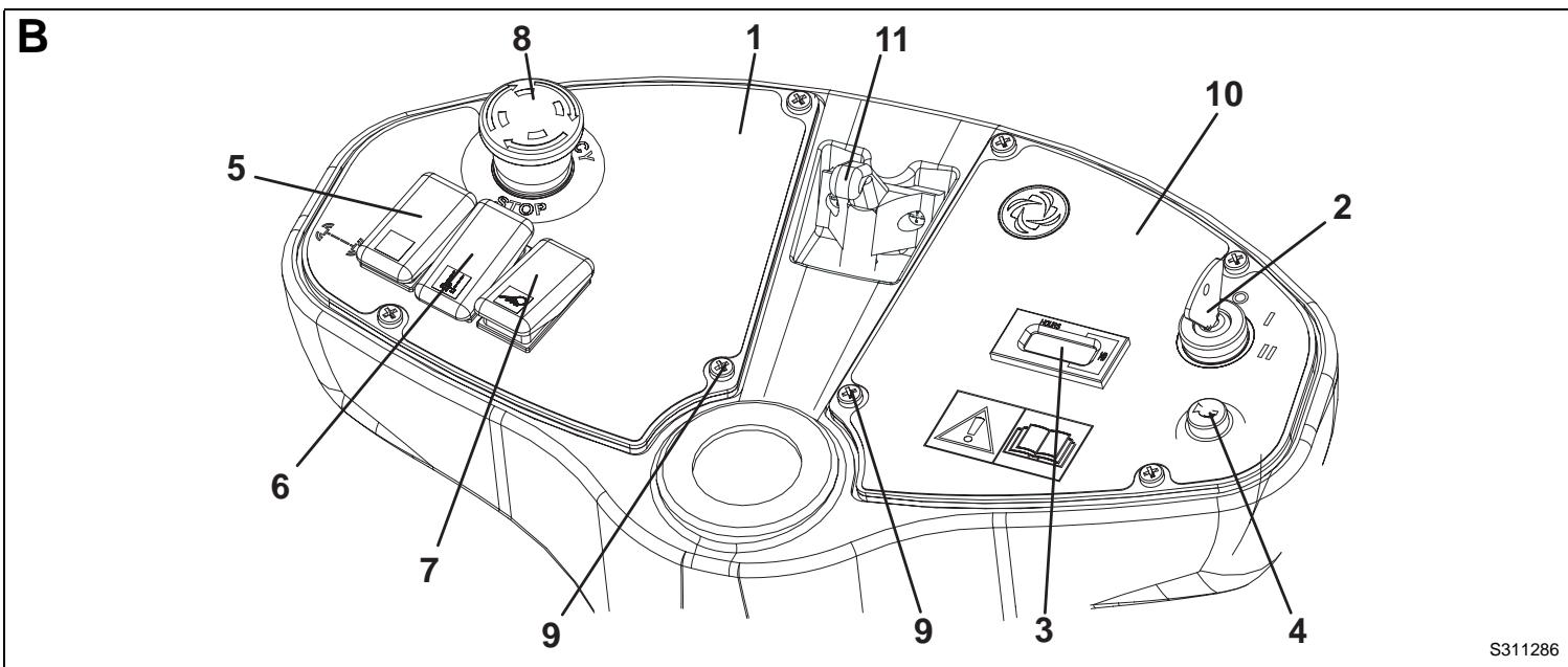
CONTROL PANEL
(See Fig. B)
- Left control panel
- Ignition switch
- Hour counter
- Horn switch
- Filter shaker switch
- Manual vacuum system switch (optional)
- Working light switch (optional)
- Emergency push-button
- Control panel mounting screws
- Right control panel
- Steering column inclination adjusting lever
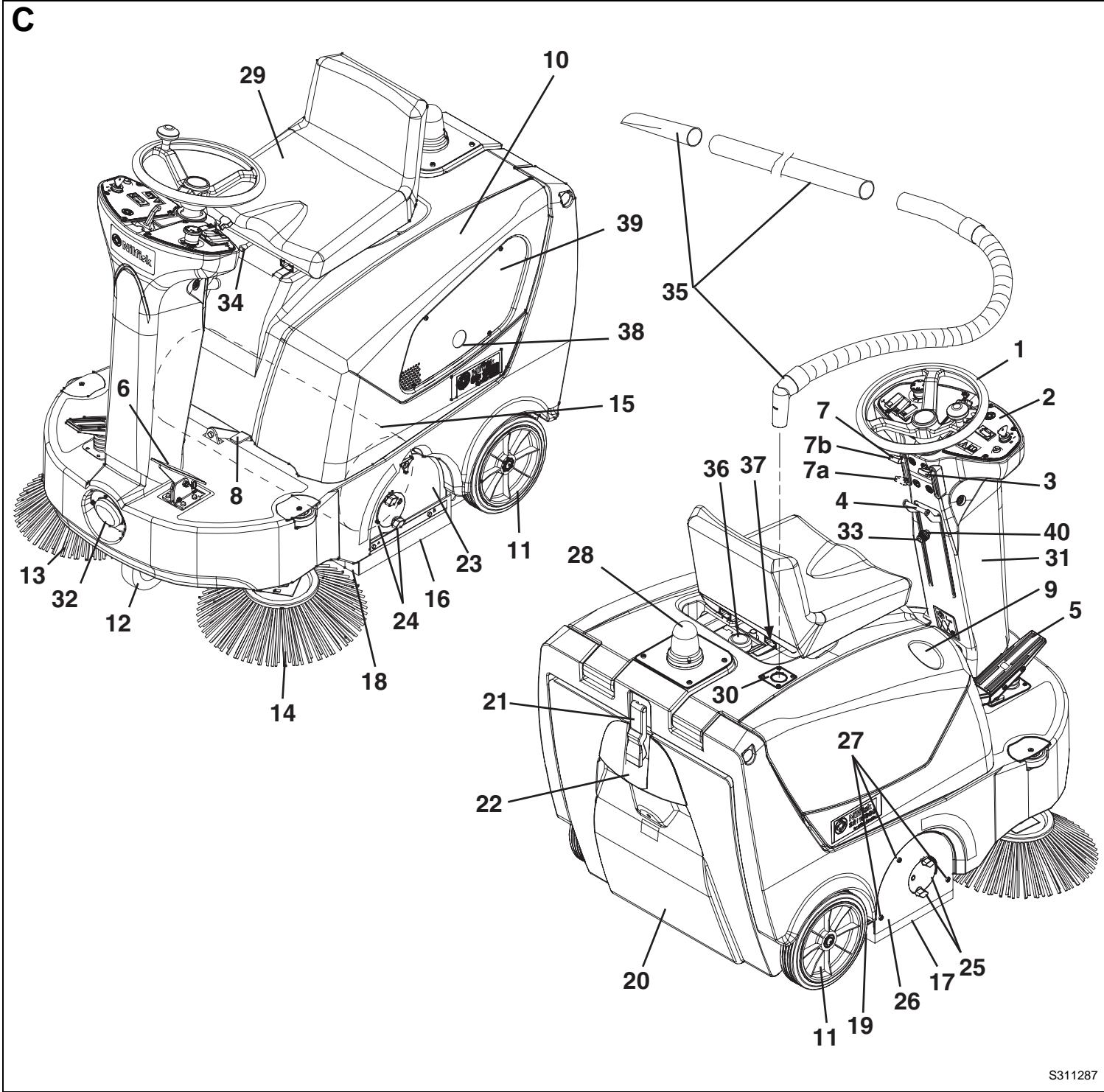
OUTSIDE VIEW
(See Fig. C)
- Steering wheel
- Control panel
- Vacuum activation/deactivation lever
- Side broom lifting/lowering lever
- Forward/reverse gear pedal
- Service brake pedal
- Parking brake lever (it acts on the front wheel)
7a. Brake engaged
7b. Brake disengaged - Front skirt lifting pedal
- Can holder
- Hood
- Rear wheels on fixed axle
- Front driving and steering wheel
- Right side broom
- Left side broom
- Main broom
- Left side skirt
- Right side skirt
- Front skirt
- Rear skirt
- Hopper
- Hopper hook
- Hopper handle
- Main broom left door
- Main broom height left adjusting knob
- Main broom height right adjusting knob
- Main broom right door
- Main broom right door mounting screws
- Pivoting light (always on when the ignition switch is turned to "I" position) (optional)
- Driver's seat with safety microswitch
- Additional hole for manual vacuum system (optional)
- Adjustable steering column
- Working light (optional)
- Side broom height adjusting knob
- Seat longitudinal position adjusting lever
- Manual vacuum system (optional)
- Fuel tank cap
- Fuel tap and engine choke lever compartment
- Engine exhaust pipe
- Engine ventilation grid
- Side broom height adjusting knob ring nut
UNDER-HOOD COMPARTMENT
(See Fig. U)
- Serial number plate/technical data/EC certification
- Engine model
- Engine serial number
- Hood (open)
- Hood support rod
- Petrol engine
- Ignition spark plug
- Engine choke lever
- Fuel tap
- Fuel tank
- Fuel tank cap
- Engine air filter
- Accelerator lever (adjusted by the Manufacturer: do not tamper with it nor use it to change the engine speed!)
- Engine oil filler/level check plug
- Engine oil drain plug
- Engine belt
- Main broom belt
- Main broom drive pulley
- Vacuum fan
- Engine silencer
- Batteries
- Battery caps
- Lamellar fuse box (accessories)
- Drive system thermal fuse
- Starter and dynamo
- Manual vacuum system (optional)
- Switch for machine pushing
- Battery installation diagrams
- Dynamofuse
(See Fig. V)
- Fuel tap
(See Fig. W)
- Engine choke lever
TECHNICAL DATA
| General | Values |
| Machine length | 1,255 mm |
| Machine width (without side brooms) | 795 mm |
| Machine height (steering wheel with knob) | 1,173 mm |
| Cleaning width (with side brooms) | 1,000 mm |
| Main broom size | Ø 265 mm x 600 mm |
| Side broom size | Ø 420 mm |
| Front driving and steering wheel | Ø 200 x 50 mm |
| Rear wheels | Ø 250 x 50 mm |
| Total machine weight (with batteries) | 284.31 kg |
| Maximum forward/reverse speed | 5.5 km/h / 4.4 km/h |
| Gradeability | 16% |
| Hopper capacity | 50 litres |
| Cleaning rate (with main broom) | 3,060 m²/h |
| Cleaning rate (with main and side brooms) | 5,100 m²/h |
| Sound pressure level (LpA) | 77.4 dB (A) |
| Batteries | Values |
| Battery voltage | 24 V |
| Starter batteries | 2x12 V/80 Ah |
| Petrol engine | Data的价值 |
| Make | Honda |
| Model | GX100 |
| Displacement | 98 cm³ |
| Engine power | 2.2 kW |
| Specific fuel consumption | 327 g/kW·h |

NOTE
For other petrol engine data/values, see the relevant Manual.
| Dust vacuuming and filtering | Values |
| Dust filter (one side) | 3 m² |
| Filter shaker activation | Electric |
Wiring diagram (See Fig. X)
BAT: 24 V batteries
BE1: Pivoting light
BLK: Engine frame
BZ1: Reverse gear buzzer
EB1: Battery charge electronic board
EB2: Drive system electronic board
ESO: Starting relay
ES1: Engine electromagnetic switch
ES2: Filter shaker relay
ES3: Vacuum system relay (optional)
FC: Dynamofuse(50A)
FT: Drive system fuse
F1: Main fuse (ignition switch circuit) (10 A)
F2: Filter shaker fuse (25 A)
F3: Manual vacuum system fuse (40 A) (optional)
F4: Accessory fuse (15 A)
F5: Side broom fuse (10 A)
HM: Hour counter
HN1: Horn
K1: Ignition switch
L1: Working light (optional)
M1: Starter and dynamo
M2: Drive system motor
M3: Filter shaker motor
M4: Right side broom motor
M5: Left side broom motor
M6: Manual vacuum system motor (optional)
P1: Horn switch
R1: Drive speed potentiometer
SPK: Engine ignition coil (spark plug)
SWC: Hood safety switch
SWS: Emergency push-button
SW1: Manual vacuum system switch (optional)
SW2: Driver's seat safety microswitch
SW3: Forward/reverse gear microswitch
SW4: Side broom microswitch
SW5: Drive system switch
SW6: Working light switch
Colour code
BK: Black
BU: Blue
BN: Brown
GN: Green
GY: Grey
OG: Orange
PK: Pink
RD: Red
VT: Violet
WH: White
YE: Yellow
ELECTRICAL FUSES
The following fuses are located under the hood (10, Fig. C):
Circuit breakers, which can be reset by pressing the relevant key:
Drive system (24, Fig. U)
Lamellar fuses, protected by a transparent plastic cover, which protect the following circuits:
(23, Fig. U, from the top):
F1 (10 A): Main fuse (ignition switch circuit)
F2 (25 A): Filter shaker motor
F3 (40 A): Manual vacuum system (optional)
F4 (15 A): Accessories
F5 (10 A): Side broom motors
F6 (25 A): Spare
F7 (15 A): Spare
F8 (10 A): Spare
(29, Fig. U):
FC (50 A): Dynamo
ACCESSORIES/OPTIONS
In addition to the standard components, the machine can be equipped with the following accessories/options, according to the machine specific use:
- Main and side brooms with harder or softer bristles
- Antistatic polyester or polyester BIA C dust filter
Manual vacuum system
Working light
Pivoting light
Skirts of various materials
For further information concerning the optional accessories, contact an authorised Retailer.
USE

WARNING!
On some points of the machine there are some adhesive plates indicating:
DANGER
-WARNING
- CAUTION
- NOTE
While reading this Manual, the operator must pay particular attention to these symbols.
Do not cover these plates for any reason and immediately replace them if they are damaged.
BEFORE MACHINE START-UP

CAUTION!
Make sure that there are no open doors/woods and that the machine is in normal operating conditions.
Make sure that the hopper (20, Fig. C) is properly closed.
If the machine has not been used after being transported, check that all the blocks used for the transportation have been removed.
- If necessary, remove the cap (36, Fig. C) and refuel the machine; if necessary, to gain access to the cap (36), move the seat (29) forward with the adjusting lever (34).

CAUTION!
Do not fill the fuel tank beyond the upper limit mark (1, Fig. T).
- Open the hood (10, Fig. C) and open the fuel tap (1, Fig. V), then close the hood again.
MACHINE START AND STOP
Starting the machine
- Sit on the driver's seat (29, Fig. C) and, if it is necessary for an easier access to the machine, push the lever (11, Fig. B) and tilt the steering column (31, Fig. C) forward.
- Push the lever (11, Fig. B) forward and tilt the steering column (31, Fig. C) forward or backward, to reach a comfortable position. Then release the lever (11, Fig. B) and lock the steering column.
-
Only in case of very low temperatures, turn the engine choke lever (1, Fig. W) to closed position (2) by introducing your hand into the compartment (37, Fig. C), without opening the hood (10, Fig. C).
-
Turn the ignition switch (2, Fig. B) to "II" and start the engine. When the engine starts, release the ignition switch immediately.

CAUTION!
When starting the engine with the ignition switch (2, Fig. B) do not press the drive pedal (5, Fig. B).

CAUTION!
Engine cannot start when the hood (10, Fig. C) is open. A safety system prevents the engine from starting.

CAUTION!
When the engine is running, the main broom rotates, while the side brooms do not move, if lifted.
When the engine is running, the vacuum fan is always operating.
- 5 seconds after the engine has been running, disengage the engine choke lever (1, Fig. W) by introducing your hand into the compartment (37, Fig. C), without opening the hood (10, Fig. C).
-
Disengage the parking brake according to the following procedure:
-
Press the pedal (6, Fig. C) and turn the lever (7, Fig. C) from (7a) position to (7b) position.
-
Release the pedal (6).
-
Drive the machine to the working area, by keeping the hands on the steering wheel and pressing the pedal (5, Fig. C) on the front side to move forward and on the rear side to move backward.
The drive speed can be adjusted from zero to maximum speed by increasing the pressure on the pedal (5, Fig. C).

NOTE
The seat (29, Fig. C) is equipped with a safety sensor, which allows the machine to be driven by pressing the pedal (5, Fig. C) only when the operator is on the driver's seat.
- Turn on the vacuum system with the lever (3, Fig. C).
- Lower the side brooms (13 and 14, Fig. C) by lowering the lever (4).

NOTE
The side brooms (13 and 14, Fig. C) can be lowered and lifted even when the machine is moving.
The side brooms do not rotate when they are lifted, but they rotate when they are lowered.
- Start sweeping by turning the steering wheel (1, Fig. C) and move the machine forward by pressing the pedal (5).
Stopping the machine
- To stop the machine, release the pedal (5, Fig. C). To stop the machine more quickly, also press the service brake pedal (6, Fig. C). In case of emergency, press the emergency push-button (8, Fig. B) to immediately stop the machine. To deactivate the emergency push-button (8), turn it clockwise.
- To turn off the side brooms (13 and 14, Fig. C), lift them by using the lever (4).
- To turn off the main broom (15, Fig. C), the vacuum fan (19, Fig. U) and the engine, turn the ignition switch (2, Fig. B) to "0" position.
-
Engage the parking brake according to the following procedure:
-
Press the pedal (6, Fig. C) as necessary, then engage the brake by turning the lever (7, Fig. C) from (7b) position to (7a) position.
-
Release the pedal (6).
-
Open the hood (10, Fig. C) and close the fuel tap (1, Fig. V), then close the hood again.
MACHINE OPERATION
- Avoid stopping for a long time with the machine in the same position and the brooms rotating: this could create unwanted marks on the floor.
- To collect light and bulky debris, lift the front skirt by pressing the pedal (8, Fig. C); remember that while the front skirt is lifted, the machine vacuum power decreases.

CAUTION!
When operating on wet grounds, it is essential to turn off the vacuum system with the lever (3, Fig. C) to prevent the dust filter from being damaged.
- For machine proper operation, the dust filter must be as clean as possible. To keep the dust filter clean while sweeping, turn off the vacuum system with the lever (3, Fig. C), then press the filter shaker switch (5, Fig. B) for a while.
After cleaning the filter, turn on the vacuum system with the lever (3, Fig. C).
While working, repeat the procedure every 10 minutes on average (depending on the dustiness of the area to be cleaned).

NOTE
When the dust filter is clogged and/or the hopper is full, the machine cannot collect dust and debris anymore.
The hopper (20, Fig. C) should be dumped after each working period and whenever it is full (see the procedure in the next paragraph).

CAUTION!
The engine is equipped with a warning system to prevent damages to the engine itself in case the oil quantity in the carter is insufficient. Before the oil level goes below the safety limit, the warning system automatically stops the engine.
HOPPER DUMPING
- Stop the machine by releasing the drive pedal.
- Turn the ignition switch (2, Fig. B) to "0" position.
- Disengage the hook (21, Fig. C) by pulling its lower end.
- Remove the hopper (20, Fig. C) by using the handle (22), and dump it into special containers.
- Reinsert the hopper and fasten it with the hook (21).
- The machine is ready to start working again.
AFTER MACHINE USE
After working, before leaving the machine:
- Lift the side brooms with the lever (4, Fig. C).
- Turn off the vacuum system with the lever (3, Fig. C).
- Turn on the filter shaker with the switch (5, Fig. B).
- Turn the ignition switch (2, Fig. B) to "0" position and remove the key.
- Close the fuel tap (1, Fig. V) in the compartment (37, Fig. C).
- Dump the hopper (20, Fig. C) (see the previous paragraph).
-
Engage the parking brake according to the following procedure:
-
Press the pedal (6, Fig. C) as necessary, then engage the brake by turning the lever (7, Fig. C) from (7b) position to (7a) position.
- Release the pedal (6).
To easily push/tow the machine when it is off, proceed as follows:
- Open the hood (10, Fig. C).
- Turn the switch (27, Fig. U) to "0" position and close the hood (10, Fig. C).
- Push or tow the machine.
- After pushing/towing the machine, turn the switch (27, Fig. U) back to "l" position.
MACHINE LONG INACTIVITY
If the machine is not going to be used for more than 30 days, proceed as follows:
- Check that the machine storage area is dry and clean.
- Disconnect the negative terminal from the batteries (21, Fig. U).
- Slightly lift the machine so that the skirts, the main broom and the wheels do not touch the ground.
- Handle the engine according to the instructions in the relevant Manual.
FIRST PERIOD OF USE
After the first 8 hours, check the machine fastening and connecting parts for proper tightening and check the visible parts for integrity and leakage.
After the first 20 hours of work, or after the first month, change the engine oil (see the relevant Manual).
MAINTENANCE
The lifespan of the machine and its maximum operating safety are ensured by correct and regular maintenance.
The following table provides the scheduled maintenance. The intervals shown may vary according to particular working conditions, which are to be defined by the person in charge of the maintenance.

WARNING!
To carry out maintenance procedures, switch off the machine (remove the key from the ignition switch) and, if necessary, disconnect the batteries. Moreover, carefully read the instructions in the Safety paragraph.
All scheduled or extraordinary maintenance procedures must be performed by qualified personnel, or by an authorised Service Center.
This Manual describes only the easiest and most common maintenance procedures.

NOTE
For other maintenance procedures included in the Scheduled Maintenance table, see the Petrol Engine Manual and/or the Service Manual.
SCHEDULED MAINTENANCE TABLE
| Procedure | On delivery | Every 10 hours (1) | First month or after 20 hours (1) | Every 50 hours (1) | Every 100 hours (1) | Every 200 hours (1) | Every 400 hours (1) | Every 2 years |
| Battery fluid level check | (2) | |||||||
| Engine oil level check | (2) (7) | |||||||
| Engine air filter check | (2) (7) | |||||||
| Side and main broom height check and adjustment | ||||||||
| Dust filter cleaning and integrity check | (2) | |||||||
| Engine oil change | (7) | (4) (7) | ||||||
| Engine air filter cleaning | (5) (7) | |||||||
| Skirt height and operation check | ||||||||
| Filter shaker operation check | (3) | |||||||
| Hood safety switch operation check | ||||||||
| Engine and main broom drive belt visual inspection | (3) | (3) | ||||||
| Engine spark plug check/cleaning | (7) | |||||||
| Fuel tank and filter cleaning | (6) | |||||||
| Nut and screw tightening check | (3) (1) | |||||||
| Engine speed check | (3) | |||||||
| Service and parking brake check and adjustment | (3) | |||||||
| Engine and main broom drive belt replacement | (3) (8) | |||||||
| Engine air filter replacement | (5) (7) | |||||||
| Spark plug replacement | (4) (7) | |||||||
| Engine valve clearance check/adjustment | (6) | |||||||
| Engine combustion chamber cleaning | (6) (9) | |||||||
| Starter-dynamo and drive system motor carbon brush check and replacement | (3) | |||||||
| Fuel pipe check/replacement | (6) |
(1): And after the first 8 running-in hours.
(2): Or before use.
(3): For the relevant procedure, see the Service Manual.
(4): Or every year.
(5): Or more often in dusty areas.
(6): Maintenance procedures to be performed by an authorised Honda Dealer, unless the operator has the service equipment and data, and is qualified to perform such procedures.
(7): For the procedure, see the Petrol Engine Manual.
(8): If the person in charge for the maintenance consider it necessary.
(9): Or every 300 hours, if necessary.
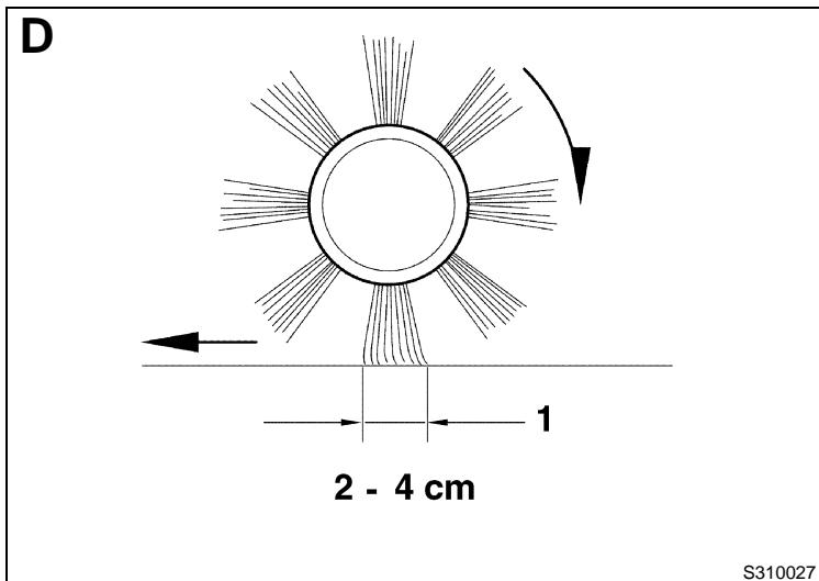
MAIN BROOM HEIGHT CHECK AND ADJUSTMENT

NOTE
Brooms of various hardness are available. This procedure is applicable to all types of brooms.
- Check that the main broom is at the correct height from the ground, according to the following procedure:
Drive the machine on a level ground.
- Keep the machine stationary and rotate the main broom for a few seconds.
- Stop the main broom, then move the machine and switch it off.
- Check that the main broom print (1, Fig. D), along its length, is 2 to 4 cm wide.
If the print (1) is not within specifications, it is necessary to adjust the broom height, according to the procedure shown in step 2.
- Drive the machine on a level ground and engage the parking brake (6 and 7, Fig. C).
- Turn the ignition switch (2, Fig. B) to "0" position.
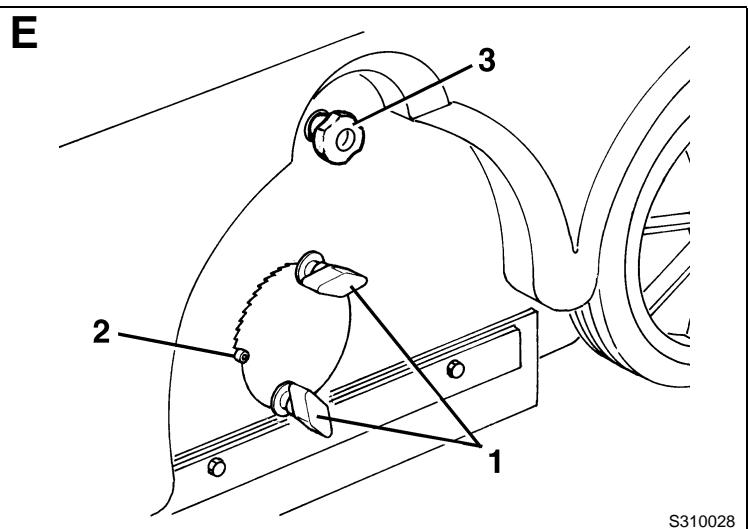
- Loosen the knobs (1, Fig. E) on both sides of the machine.
- Operating on the knobs (1, fig. E) move, on both sides of the machine, the broom height variation indicator (2) as necessary and then screw down the knobs (1).
The indicator (2) must be at the same position on both sides of the machine; the maximum difference allowed is 2 notches to obtain the print (1, Fig. D) from 2 to 4cm as shown in step 1.
- Perform step 1 again to check that the main broom is at the correct height from the ground.
- When the broom is too worn and can no longer be adjusted, replace it according to the instructions in the following paragraph.

CAUTION!
An excessive print (larger than 4cm ) of the main broom can lead to the machine malfunction and the overheating of the moving parts, thus reducing machine life.
Pay careful attention when performing the above-mentioned checks, and always use the machine according to the indicated conditions.
MAIN BROOM REPLACEMENT

NOTE
Brooms of various hardness are available. This procedure is applicable to all types of brooms.

CAUTION!
It is advisable to use protective gloves when replacing the side brooms because there can be sharp debris between the bristles.
- Drive the machine on a level ground and engage the parking brake (6 and 7, Fig. C).
- Turn the ignition switch (2, Fig. B) to "0" position.
- Loosen the knobs (1, Fig. E) on both sides of the machine.
- Move the broom height variation indicators (2, Fig. E) until the broom is at the maximum distance from the ground. Screw down the knobs (1).
- On the left side of the machine, loosen the knob (3, Fig. E).
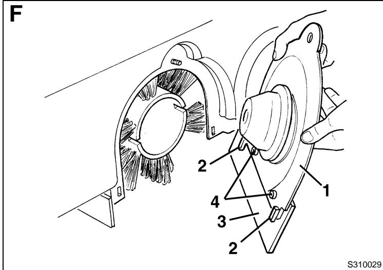
- Remove the broom door (1, Fig. F) by pulling it upwards to disengage the retainers (2).
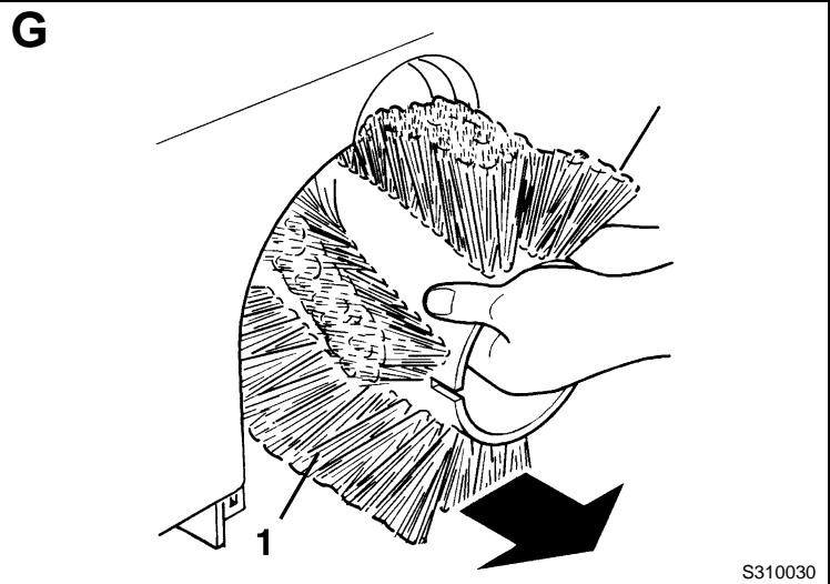
- Remove the broom (1, Fig. G).
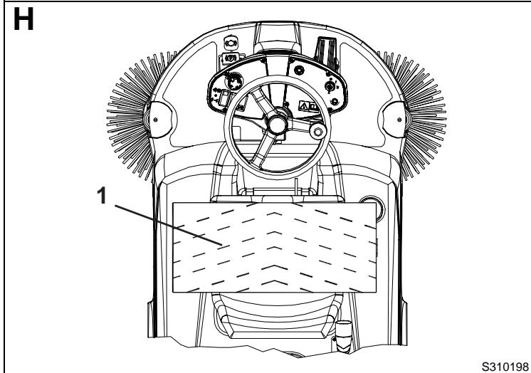
- The new broom must be installed with the bristles rows bent as shown in the figure H (top view).
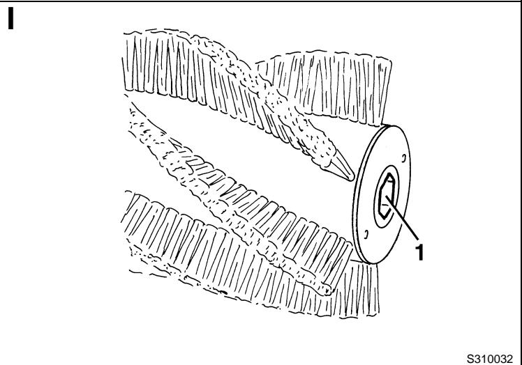
- Install the new broom on the machine and ensure that its mesh (1, Fig. 1) correctly fits into the relevant drive hub (4, Fig. R). Check that the drive hub is free from dirt or foreign materials (cords, rags, etc.) accidentally rolled up.
- Install the broom door (1, Fig. F) by engaging the retainers (2).
- Screw down the knob (3, Fig. E).
- Carry out the main broom height check and adjustment, as shown in the previous paragraph.
SIDE BROOM HEIGHT CHECK AND ADJUSTMENT

NOTE
Brooms of various hardness are available. This procedure is applicable to all types of brooms.
-
Check the side broom height from the ground, according to the following procedure:
-
Drive the machine on a level ground and lower the side brooms.
- Keep the machine stationary and rotate the side brooms for a few seconds.
- Stop and lift the side brooms, then move the machine and switch it off.
-
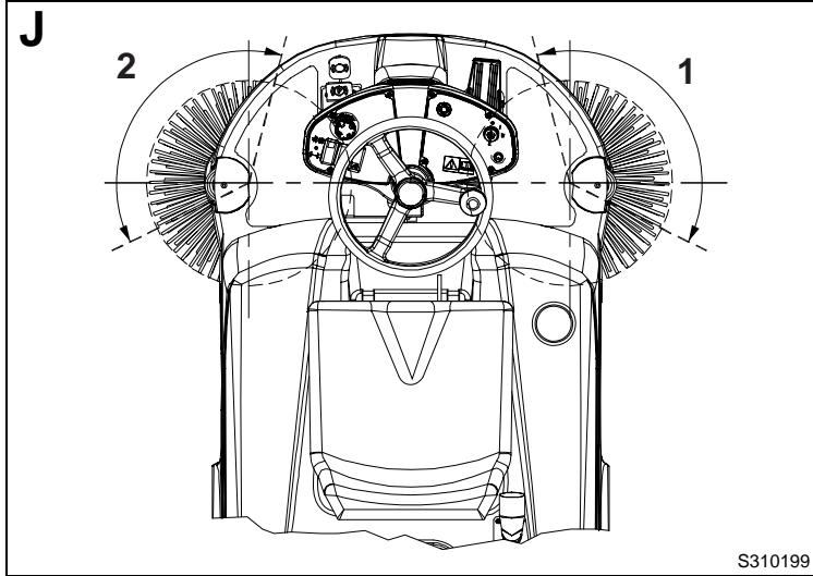
Check if the size and orientation of the prints left by the side brooms are as shown in the figure (1 and 2, Fig. J). If the print is not within specifications, it is necessary to adjust the broom height, according to the procedure shown in step 2.
-
Unlock the ring nut (40, Fig, C) by turning it counterclockwise, then turn the knob (33) as necessary, clockwise or counterclockwise, to adjust the broom height; then lock the knob (33) with the ring nut (40).
- Perform step 1 again to check the proper adjustment of the side broom height from the ground.
- When the brooms are too worn to be adjusted, replace them as shown in the next paragraph.
SIDE BROOM REPLACEMENT

NOTE
Brooms of various hardness are available. This procedure is applicable to all types of brooms.

CAUTION!
It is advisable to use protective gloves when replacing the side brooms because there can be sharp debris between the bristles.
- Drive the machine on a level ground and engage the parking brake (6 and 7, Fig. C).
- Turn the ignition switch (2, Fig. B) to "0" position.
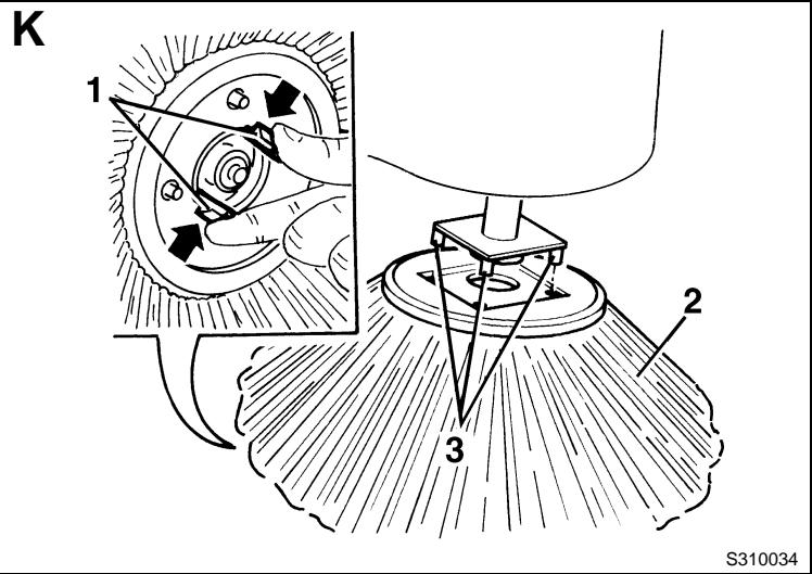
- Introduce the hand inside the side broom and press the tabs (1, Fig. K) inwards, then remove the broom (2) disengaging it from the four pins (3).
- Install the new broom on the machine engaging it on the pins (3) and on the tabs (1).
- Carry out the side broom height check and adjustment, as shown in the previous paragraph.
DUST FILTER CLEANING AND INTEGRITY CHECK

NOTE
Besides the standard paper filter, polyester filters are also available. The following procedure is applicable to each type of filter.
- Drive the machine on a level ground and engage the parking brake (6 and 7, Fig. C).
- Turn the ignition switch (2, Fig. B) to "0" position.
- Remove the hopper hook (21, Fig. C).
- Remove the hopper (20, Fig. C) by using the handle (22).
- Turn the handle (1, Fig. L) downwards ( 90^ approximately) and let the filter frame (2) rotate outwards.
- Remove the dust filter (3).
- In an appropriate outdoor area, clean the filter by shaking it on a level and clean surface, tapping the side (1, Fig. M) opposite to the wire gauze (2). Complete the cleaning by using compressed air (3) at maximum 6 bars, blowing only from the side protected by the wire gauze (2), at a minimum distance of 30~cm (see the figure).
According to the filter type, observe the following cautions:
-
Paper filter (standard): Do not use water or detergents to clean it; the filter can be damaged.
Polyester filter (optional): To clean it, see the above-mentioned instructions. If necessary, for a better cleaning, it is allowed to wash the filter with water and non-lathering detergents. This provides better quality cleaning but reduces the life of the filter, which will have to be replaced more frequently. The use of inadequate detergents can damage the filter. -
Check the filter body for tears.
- If necessary, clean the filter compartment rubber seal (4, Fig. L) along its perimeter and check it for integrity. If necessary, replace it.
- Assemble in the reverse order of disassembly.

NOTE
Assemble the filter with the wire gauze (2, Fig. M) facing the vacuum fan (19, Fig. U).
- Drive the machine on a level ground that is suitable for checking the skirt height. Engage the parking brake (6 and 7, Fig. C).
- Turn the ignition switch (2, Fig. B) to "0" position.
Side skirt check
- Check the side skirts (16 and 17, Fig. C) for integrity. Replace the skirts when they have cuts (1, Fig. N) larger than 20mm or cracks (2) larger than 10mm (for skirt replacement, refer to the Service Manual).
- Check that the side skirt (16 and 17, Fig. C) height from the ground is within 0 - 3mm (Fig. O). If necessary, adjust the skirt height, according to the following procedure:
Left skirt:
- Open the machine hood (10, Fig. C) and engage the hood support rod (5, Fig. U).
- Loosen the knob (3, Fig. E) and remove the broom left door (1, Fig. F), pulling it upwards to disengage the retainers (2).
- Adjust the skirt (3, Fig. F) height by using the slots (4).
-
Assemble in the reverse order of disassembly. Right skirt:
-
Remove the main broom, as shown in the relevant paragraph.
- Remove the belt (17, Fig. U) from the pulley (18); for a easier removal, turn the pulley (18) by operating on the vacuum fan (19) manually.
- Remove the screws (27, Fig. C) and the right door (26) together with the belt (17, Fig. U). Adjust the skirt (1, Fig. S) height by using the slots (2).
- Assemble in the reverse order of disassembly.
Front and rear skirt check
- Remove the main broom, as shown in the relevant paragraph.
- Check the front (1, Fig. R) and rear (2) skirts for integrity.
- Replace the skirts when they have cuts (1, Fig. N) larger than 20mm or cracks (2) larger than 10mm (for skirt replacement, refer to the Service Manual).
-
Check that:
-
The front skirt (1, Fig. R) slightly touches the ground and that it is not detached from the ground (1, Fig. P).
-
The rear skirt (2, Fig. R) height from ground is within 0 - 3mm (1, Fig. O).
-
If necessary, adjust the skirt height by using the slots (3, Fig. R).
- Press the front skirt lifting pedal (8, Fig. C) and check that the front skirt (1, Fig. Q) rotates upward of about 90^ (as shown in figure); release the pedal and check that the skirt does not remain in an intermediate position but returns to its initial position. If necessary, for the front skirt control cable adjustment or replacement, refer to the Service Manual.
- Assemble in the reverse order of disassembly.
HOOD SAFETY SWITCH OPERATION CHECK
While the engine is running, slightly open the hood (10, Fig. C) and check that the engine stops immediately.
If opening the hood (10) does not cause the engine to stop, contact an authorised Service Center or Retailer.
SAFETY FUNCTIONS
The machine is equipped with the following safety functions.
EMERGENCY PUSH-BUTION
It is located in an easily accessible position (8, Fig. B). It has to be pressed in case of emergency, to stop all the machine functions.
HOOD SAFETY SWITCH
It activates when the machine hood is opened: It stops all functions.
If the machine keeps operating when the hood is open, contact an authorised Service Center or Retailer immediately
DRIVER'S SEAT MICROSWITCH
It is located inside the driver's seat and it does not allow the machine drive system to operate if the operator is not seated on the driver's seat.
TROUBLESHOOTING
| TROUBLE | REMEDY |
| The engine does not start by turning on the ignition switch. | Check the engine oil level (1). |
| Check if the fuel tap is open. | |
| Check if there is fuel in the tank. | |
| Check if the hood is closed. | |
| Check if the fuel reaches the carburettor (1). | |
| Check if the spark plug produces a spark (1). | |
| The engine stops during operation. | Check the engine oil level (1). |
| Check if there is fuel in the tank. | |
| The side brooms do not rotate. | Lower the side brooms. |
| Check the fuse F5 in the box (23, Fig. U) for integrity. | |
| The machine does not move by pressing the pedal (5, Fig. C). | Check that the parking brake (6 and 7, Fig. C) has been released. |
| Check that the switch (27, Fig. U) is in "I" position. | |
| Check that the drive pedal (5, Fig. C) is not pressed while starting the machine with the ignition switch (2, Fig. B), or while the operator is sitting on the driver's seat. The drive pedal (5, Fig. C) has to be pressed only after the operator has sit on the driver's seat and the machine has been started. |
(1): For the procedure, see the Petrol Engine Manual.
For further information, refer to the Service Manual, available at any Nilfisk-Advance Service Center.
SCRAPPING
Have the machine scrapped by a qualified scraper.
Before scrapping the machine, remove the following
materials, which must be disposed of properly according to the law in force.
Polyester dust filter
Main and side brooms
Engine oil
- Electrical and electronic components (*)
- Plastic components and hoses
(*) Refer to the nearest Nilfisk-Advance Center especially when scrapping electrical and electronic components.
INLEIDING 2
DOEL EN INHOUD VAN DEZE HANDLEIDING 2
BETREFFENDE PERSONEN 2
OPBERGEN VAN DE HANDLEIDING 2
BEWIJS VAN CONFORMITEIT 2
IDENTIFICATIEGEGEVENS 2
ANDERE GEBRUIKERSHANDLEIDINGEN 2
VERVANGINGSONDERDELEN EN ONDERHOUD 2
MODIFICATIONS EN VERBETERINGEN 2
VEILIGHEID 3
GEBRUIKTE SYMBOLEN 3
ALGEMENE INSTRUCTIES 3
VERPAKKING VERWIJDEREN/AFLEVERING 4
BESCHRIJVING VAN DE MACHINE 5
BEDRIJFSCAPACITEIT 5
ALGEMENE OPMERKINGEN 5
BEDIENINGSPANEEL EN KNOPPEN 5
BUITENZIJDE (ALGEMEEN) 5
RUIMTE ONDER DE KLEP 6
ACCESSIONS / OPTIES 7
GEBRUK 8
VOOR HET STARTEN VAN DE MACHINE 8
DE MACHINE STARTEN EN STOPPEN 8
MACHINE IN BEDRIJF 9
DE AFVALCONTAINER LEGEN 9
NA GEBRUIK VAN DE MACHINE 9
DUW-/TREKBEWEGING VAN DE MACHINE 9
LANGE PERIODE VAN STILLSTAND 10
F4: Zekering services (15 A)
ACCESSORIES / OPTIES
- GEVAAR!
- LETOP!
WAARSCHUWING - OPMERKING