
RS 851 - Industrial sweeper NILFISK - Free user manual and instructions
Find the device manual for free RS 851 NILFISK in PDF.
| Product type | Industrial sweeper |
| Brand | NILFISK |
| Model | RS 851 |
| Length | 3,630 mm (142.9 in) without options |
| Width | 1,350 mm (53.1 in) |
| Height (with beacon) | 2,470 mm (97.2 in) |
| Total weight in working order | 2,730 kg (6,019 lb) without operator |
| Maximum authorized total mass | 3,750 kg (8,267 lb) |
| Power source | Diesel engine VM D703 IE3, 48 kW (64.4 HP), fuel tank 65 L |
| Main functions | Sweeping, suction, water dust suppression, filtration, transport and waste dumping |
| Cleaning width (2 brushes) | 1,600 mm (63.0 in) |
| Cleaning width (3 brushes) | 2,100 mm (82.7 in) |
| Waste container capacity | 850 liters (224.5 US gal) |
| Maximum working speed | 12 km/h (7.4 mph) |
| Maximum negotiable slope | 22% |
| Braking system | Hydraulic service brake, mechanical parking brake |
| Scheduled maintenance | Intervals MA0 (150 h) and MA1 (500 h) with indicator on display |
| Spare parts and repairability | Original Nilfisk parts, spare parts catalog, approved technical support |
| Safety | Emergency stop button, operator presence sensors, parking brake, seat belt, automatic stop in emergency |
| General information | User manual in French, diesel engine manual, electrical diagram, possible road approval |
Frequently Asked Questions - RS 851 NILFISK
User questions about RS 851 NILFISK
0 question about this device. Answer the ones you know or ask your own.
Ask a new question about this device
Download the instructions for your Industrial sweeper in PDF format for free! Find your manual RS 851 - NILFISK and take your electronic device back in hand. On this page are published all the documents necessary for the use of your device. RS 851 by NILFISK.
USER MANUAL RS 851 NILFISK
EC Machinery Directive 2006/42/EC EC EMC Directive 2004/104/EC
EN ISO 12100-1, EN ISO 12100-2, EN 294, EN 349, EN 982, EN 13019, EN 15429-1
EN 55012, EN 50366
Manufacturer: Nilfsk-Advance S.p.A.
Oprized signatory: Franco Mazzini, General
Date: Signature
Address: Strada Comunale della Braglia, 18, 26862 GUARDAMIGLIO (LO) - ITALY Tel.: +30 (0)277.451124 Fax: +30 (0)277.514143
Technical file compiled by the manufacturer
B
C
S310809
Model: RS 851
Serial No: 08XXXXXXXXX
Total Weight: KG 2600
KW48
Prod. Nr: 13300113
Date code : H07
3 dB(A)80,5
Battery: 12VDC


Nilfisk Advance
setting standards
Manufactured By: Nilfisk - Advance S.p.a. 26862 Guardamiglio (LO) - Italy www.nilfisk-advance.com

Made in Italy
S311278
D
S311305
E
S311315
F
S311317
G
S311261

I_6
S311310
1_7
S311306
1_8
S311308
J_1
S311296
J_2
S311297
J_3
S311320
K
S311298
L
S311299

U
S310823
S310824
W
S310825
S310826
Y
S310827
S310828
AA
S310829
AB
S310830
AI
S310837
AJ
S310838
AK
S311263
AL
S310840
AM
S311264
AN
S310842
AO
S310843
S310845
AR1
S311288
AR2
S311289
AS
S310847
AT
S310848
AU
S310849

AV
S311318
AW
S311316
AX
S311321
AY
S311275
AZ
S311260

INHALTSVERZEICHNIS
EINLEITUNG 3
REEMPLACEMENT DES BALAIS 37
CONTROLE DU FREIN DE STATIONNEMENT 37
CONTROLE DU Niveau D'HUILE DU MOTEUR DIESEL 37
REEMPLACEMENT DE L'HUILDE DU MOTEUR DIESEL 38
REEMPLACEMENT DU FILTRE A HUIL DE MOTEUR DIESEL 38
NETTOYAGE/REMPLACEMENTDUFILTREAAIRDU MOTEUR DIESEL 38
CONTROLE DU NETTOYAGE DES AILETTES DU RADIATEUR DU MOTEUR DIESEL 39
CONTROLE DU Niveau DU LIQUIDE DE REFROIDISSEMENT DU MOTEUR DIESEL 39
REEMPLACEMENT DU FILTRE CARBURANT DU MOTEUR DIESEL 39
REEMPLACEMENT DU PREFILTRE CARBURANT DU MOTEUR DIESEL 39
REEMPLACEMENT DU FILTRE A AIR DANS LA CABINE DE CONDUITE 39
REEMPLACEMENT DES ROUES 40
REplacement DES FUSIBLES 41
DEPOSE / REPOSE DE LA BOUCHE D'ASPIRATION 42
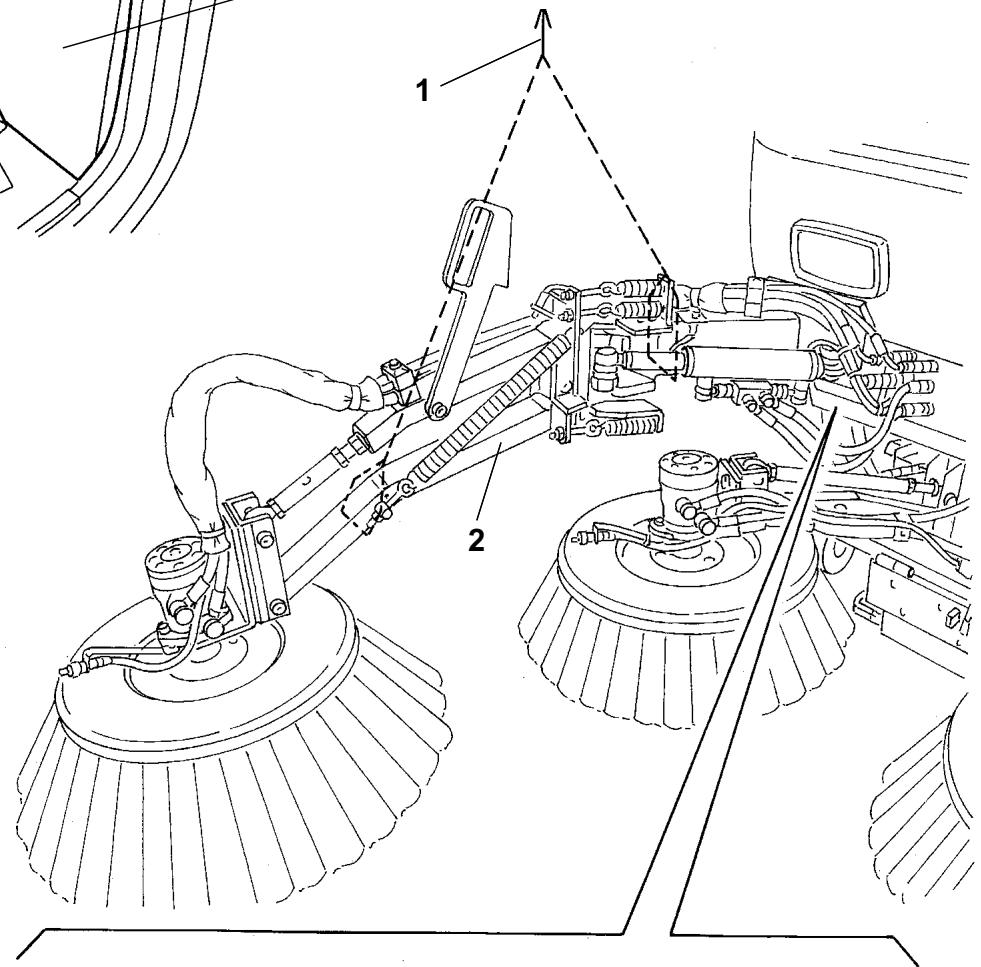
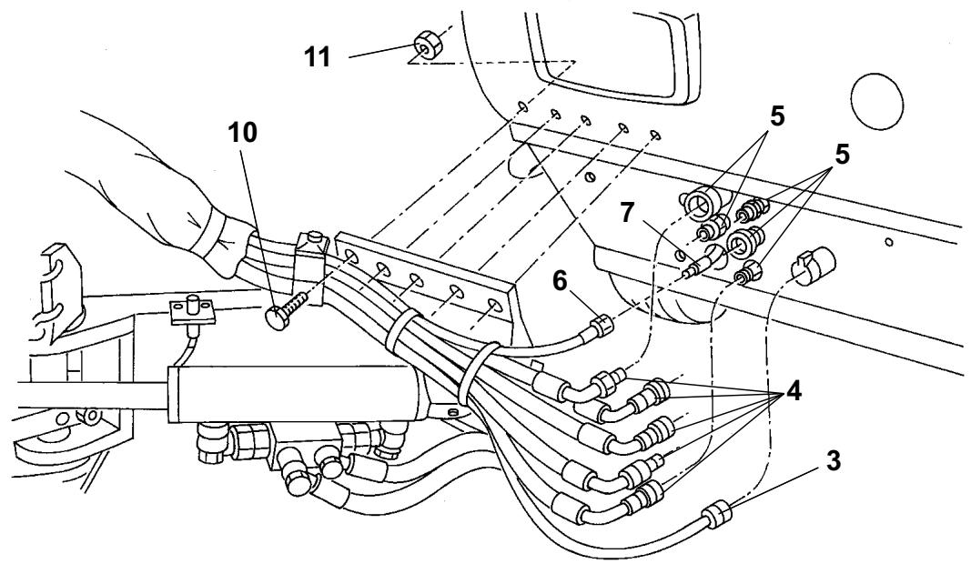
DEPOSE / REPOSE DU BRAS DU TROISIEME BALAI 42
ENTRETIEN D'HIVER 43
FONCTIONS DE SECURITE 43
DEPISTAGE DES PANNES 44
CONSERVATION DU MANUEL
ACCESSIONS / OPTIONS
TRANSPORT / DEPLACEMENT
REEMPLACEMENT DES BALAIS

REMARQUE
REEMPLACEMENT DES ROUES
MANUAL PURPOSE AND CONTENTS 3
TARGET 3
HOW TO KEEP THIS MANUAL 3
CONFORMITY CERTIFICATE 3
IDENTIFICATION DATA. 3
OTHER REFERENCE MANUALS 4
SPARE PARTS AND MAINTENANCE 4
CHANGES AND IMPROVEMENTS 4
SAFETY 4
SYMBOLS 4
GENERAL INSTRUCTIONS 5
UNPACKING/DELIVERY 7
MACHINE DESCRIPTION 7
OPERATION CAPABILITIES 7
CONVENTIONS 7
DESCRIPTION 7
TECHNICAL DATA. 12
ENVIRONMENTAL CONDITIONS 15
HYDRAULIC DIAGRAM 15
ELECTRICAL FUSES 15
ALARM DESCRIPTIONS 16
ACCESSIONS/OPTIONS 16
USE 17
GENERAL CAUTIONS 17
BEFORE START-UP 17
DIESEL ENGINE START AND STOP 18
STARTING AND STOPPING THE MACHINE 19
MACHINE OPERATION 22
HOPPER DUMPING 23
USING THE REAR SUCTION PIPE (^) 24
USING THE WINDSCREEN WIPER/WASHER 24
USING THE CAB HEATING 24
USING THE CAB CLIMATE CONTROL SYSTEM () 24
LIGHTING SYSTEM OPERATION 25
HAZARD WARNING LIGHT OPERATION 25
WORKING LIGHT OPERATION 25
HOPPER MANUAL LIFTING 25
LIFTED HOPPER SUPPORT ROD INSTALLATION 25
LIFTED HOPPER DOOR SUPPORT ROD INSTALLATION 26
USING THE HIGH-PRESSURE WATER GUN (^*) 26
USING THE CAMERA KIT (optional) 26
AFTER USING THE MACHINE 27
DUST CONTROL SYSTEM WATER TANK EMPTYING 27
TOWING THE MACHINE 27
TRANSPORTING BY TRAILER 28
MACHINE STORAGE 28
FIRST PERIOD OF USE 28
MAINTENANCE 29
SCHEDULED MAINTENANCE TABLE 29
HOPPER, FILTER AND SUCTION PIPE CLEANING, GASKET CHECK AND SUCTION FAN BEARING LUBRICATION 31
DUST CONTROL SYSTEM NOZZLE AND FILTER CLEANING 32
DUST CONTROL SYSTEM WATER FILTER CLEANING 32
HYDRAULIC SYSTEM OIL LEVEL CHECK 33
HYDRAULIC SYSTEM OIL COOLER FIN CLEANING CHECK 33
HYDRAULIC SYSTEM FILTER CHECK/REPLACEMENT 33
BATTERY FLUID LEVEL CHECK 34
3RD BROOM POSITION CHECK AND ADJUSTMENT 37
BROOM REPLACEMENT 37
ENGINE OIL FILTER REPLACEMENT 38
ENGINE AIR FILTER CLEANING/REPLACEMENT 38
ENGINE RADIATOR FIN CLEANING CHECK 39
ENGINE COOLANT LEVEL CHECK 39
ENGINE FUEL FILTER REPLACEMENT 39
FUEL PRE-FILTER REPLACEMENT 39
CAB AIR FILTER REPLACEMENT 39
WHEEL REPLACEMENT 40
FUSE REPLACEMENT 41
SUCTION INLET DISASSEMBLY/ASSEMBLY 42
3RD BROOM ARM DISASSEMBLY/ASSEMBLY 42
WINTER MAINTENANCE 43
SAFETY FUNCTIONS 43
TROUBLESHOOTING 44
PROBLEMS AND REMEDIES 44
SCRAPPING 48
INTRODUCTION
MANUAL PURPOSE AND CONTENTS
This Manual is an integral part of the machine; its purpose is to provide the operator with all necessary information to use the machine properly in a safe and autonomous way. It contains information about technical data, safety, operation, storage, maintenance, spare parts and disposal.
Before performing any procedure on the machine, the operators and qualified technicians must read this Manual carefully. Contact Nilfisk in case of doubts regarding the interpretation of the instructions and for any further information.
TARGET
This Manual is intended for operators and technicians qualified to perform the machine maintenance.
The operators must not carry out operations reserved for qualified technicians. Nilfisk will not be responsible for damages coming from failure to follow these instructions.
HOW TO KEEP THIS MANUAL
The User Manual must be kept inside the machine cab, away from liquids and other substances that can cause damage to it.
CONFORMITY CERTIFICATE
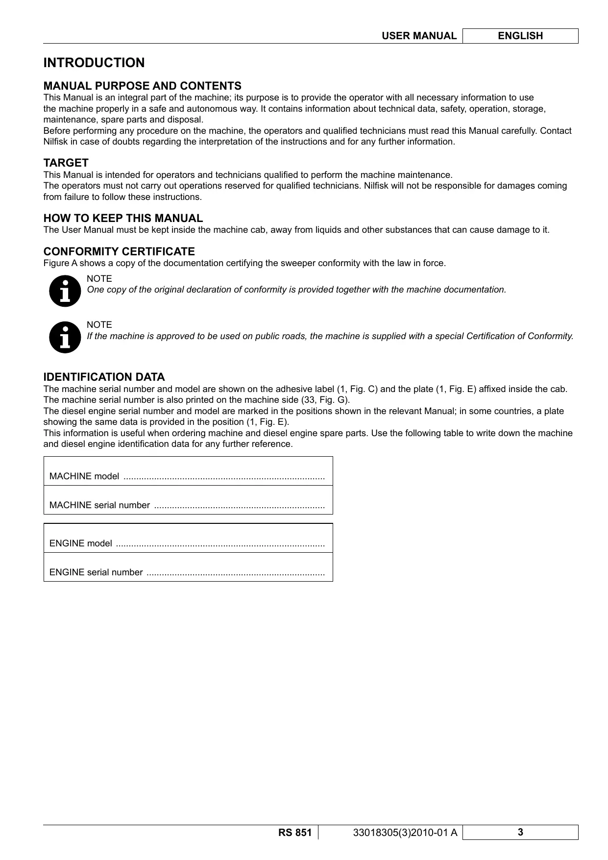
Figure A shows a copy of the documentation certifying the sweeper conformity with the law in force.

NOTE
One copy of the original declaration of conformity is provided together with the machine documentation.

NOTE
If the machine is approved to be used on public roads, the machine is supplied with a special Certification of Conformity.
IDENTIFICATION DATA
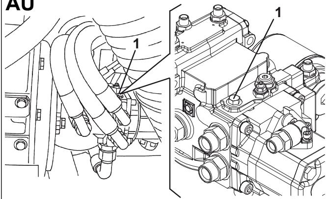
The machine serial number and model are shown on the adhesive label (1, Fig. C) and the plate (1, Fig. E) affixed inside the cab. The machine serial number is also printed on the machine side (33, Fig. G).
The diesel engine serial number and model are marked in the positions shown in the relevant Manual; in some countries, a plate showing the same data is provided in the position (1, Fig. E).
This information is useful when ordering machine and diesel engine spare parts. Use the following table to write down the machine and diesel engine identification data for any further reference.
MACHINE model
MACHINE serial number
ENGINE model
ENGINE serial number
OTHER REFERENCE MANUALS
The road sweeper is supplied with the following documentation:
Diesel Engine Manual ()
- Sweeper Spare Parts List
- Sweeper Wiring Diagram (CD and paper format)
- Camera Kit Manual (optional) ()
Camera Kit Spare Parts List (optional)
(*) These manuals are to be considered as integral part of the Sweeper User Manual.
At Nilfisk Service Centers the following Manual is also available:
- Sweeper Service Manual
SPARE PARTS AND MAINTENANCE
All necessary operating, maintenance and repair procedures must be performed by qualified personnel or by Nilfisk Service
Centers. Only original spare parts and accessories must be used.
Call Nilfisk for service or to order spare parts and accessories, specifying the machine model and serial number.
CHANGES AND IMPROVEMENTS
Nilfisk constantly improves its products and reserves the right to make changes and improvements at its discretion without being obliged to apply such benefits to the machines that were previously sold.
Any change and/or addition of accessory must be approved and performed by Nilfisk.
SAFETY
The following symbols indicate potentially dangerous situations. Always read this information carefully and take all necessary precautions to safeguard people and property.
The operator's cooperation is essential in order to prevent injury. No accident prevention program is effective without the total cooperation of the person responsible for the machine operation. Most of the accidents that may occur while working or moving around are caused by failure to comply with the simplest rules for exercising prudence. A careful and prudent operator is the best guarantee against accidents and is essential for successful completion of any prevention program.
SYMBOLS

DANGER!
It indicates a dangerous situation with risk of death for the operator.

WARNING!
It indicates a potential risk of injury for people.

CAUTION!
It indicates a caution or a remark related to important or useful functions.
Pay careful attention to the paragraphs marked by this symbol.

NOTE
It indicates a remark related to important or useful functions.

CONSULTATION
It indicates that it is necessary to consult the User Manual before performing any procedure.
GENERAL INSTRUCTIONS
Specific warnings and cautions to inform about potential damages to people and machine are shown below.

DANGER!
-
This machine must be used by properly trained and authorised personnel only.
Moreover, the operator must: -
Be 18 years or older
- Have a driving license
- Be in normal psycho-physical conditions
-
Not be under the effect of substances that alters the nervous system (alcohol, psycpharmaceuticals, drugs, etc.)
-
Remove the ignition key before performing any maintenance/repair procedure.
- This machine must be used by properly trained and authorised personnel only. Children or disabled people cannot use this machine.
- Do not wear jewels when working near moving parts.
- Do not work under the lifted machine without supporting it with safety stands.
- Do not operate the machine near toxic, dangerous, flammable and/or explosive powders, liquids or vapours.
- Be careful, fuel is highly flammable.
- Do not smoke or bring open flames in the area where the machine is refuelled or where the fuel is stored.
- Refuel outdoors or in a well-ventilated area, with the engine off.
- Do not fill the fuel tank to the top, but leave at least 1.6 in (4 cm) from the filler neck to allow the fuel to expand.
- After refuelling, check that the filler cap is tightly closed.
If any fuel is spilled while refuelling, clean up the affected area and allow the vapours to dissipate before starting the engine. - Avoid contact with skin and do not breathe in fuel vapours. Keep out of reach of children.
Before performing any maintenance/repair procedure remove the ignition key, engage the parking brake and disconnect the battery. - When working under open hoods/doors, make sure that they cannot be closed by accident.
- When performing maintenance procedures with the lifted hopper, fix it with the support rods.
- During machine transportation, the fuel tank must not be full.
- Diesel engine exhaust gases contain carbon monoxide, an extremely poisonous, colourless, and odourless gas. Do not inhale. Do not keep the engine running in a closed area.
- Do not lay any object on the engine.
-
Before working on the diesel engine turn it off. To prevent the engine from starting accidentally, disconnect the battery negative terminal.
See also the SAFETY RULES in the Diesel Engine Manual, which is to be considered an integral part of this Manual.
See also the SAFETY RULES in the Manuals of the following kit (optional), which are to be considered an integral part of this Manual: -
Camera kit

WARNING!
- To drive on public roads, the machine must follow local licensing requirements.
- The machine has been designed to be used as a sweeper, do not use it for different purposes.
- While using this machine, take care not to cause damage to people and property.
- Do not use the machine as a means of transport.
- Do not leave the machine unattended with the ignition key inserted and the parking brake disengaged.
- Do not bump into shelves or scaffoldings, particularly where there is a risk of falling objects.
- Pay careful attention when lifting and emptying the hopper.
- Adjust the operation speed to suit the ground conditions.
- Carefully read all the instructions before performing any maintenance/repair procedure.
Take all necessary precautions to prevent hair, jewels and loose clothes from being caught by the machine moving parts.
Take all necessary precautions to prevent hair, jewels and loose clothes from being caught by the machine moving parts. - Protect body parts (eyes, hair, hands, etc.) properly, when performing cleaning procedures using compressed air or water gun.
- Avoid contact with battery acid, do not touch hot parts.
- Do not allow the brooms to operate while the machine is stationary to avoid damaging the ground.
In case of fire, use a powder fire extinguisher, not a water one. - Do not wash the machine with corrosive substances.
- Do not use the machine in particularly dusty areas.
- Do not tamper with the machine safety guards and follow the ordinary maintenance instructions scrupulously.
- Do not remove or modify the plates affixed to the machine.
In case of machine malfunctions, ensure that these are not due to lack of maintenance. Otherwise, request assistance from the authorised personnel or from an authorised Service Center.
In case of part replacement, order ORIGINAL spare parts from an authorised Dealer or Retailer.
To ensure the proper and safe operation of the machine, have the scheduled maintenance, detailed in the relevant chapter of this Manual, performed by the authorised personnel or an authorised Service Center. - The machine must be disposed of properly, because of the presence of toxic-harmful materials (oils, batteries, plastics, etc.), which are subject to standards that require disposal in special centres (see Scrapping chapter).
- If the machine is used according to these instructions, the vibrations do not cause dangerous situations. Vibration level at the operator's body is 0,495 ~m / s^2 (19.5 in/s²) (ISO 2631-1) at maximum working speed (1,850 rpm).
- While the engine is running the silencer heats up. Do not touch the silencer to avoid serious scalding or fire.
- Do not run the engine if the oil level is low, to avoid damaging it seriously. Check the oil level with the engine off and the machine on a level surface.
- Do not run the engine if the air filter is not installed, to avoid damaging it.
- The engine coolant line is pressurised. Perform any check when the engine is off and after having allowed it to cool down. Even when the engine is cool, open the radiator cap carefully.
- The engine is equipped with a fan; do not stand near the engine when it is hot, because the fan can start operating even if the machine is off.
- All diesel engine servicing procedures should be performed by an authorised Dealer.
-
Only use original spare parts or parts of matching quality for the diesel engine. Using spare parts of lower quality can seriously damage the engine.
See also the SAFETY RULES in the Diesel Engine Manual, which is to be considered an integral part of this Manual.
See also the SAFETY RULES in the Manuals of the following kit (optional), which are to be considered an integral part of this Manual: -
Camera kit


WARNING!
Carbon monoxide (CO) can cause brain damage or death.
The internal combustion engine of this machine can emit carbon monoxide.
Do not inhale exhaust gas fumes.
Only use indoors when adequate ventilation is provided, and when an assistant has been instructed to look after you.
UNPACKING/DELIVERY
The machine is delivered already assembled and ready-to-use, unpacking/installation procedures are not necessary. Please check that the following items have been supplied with the machine:
Technical documents:
- Sweeper User Manual
Diesel Engine Manual - Sweeper Spare Parts List
- Wiring Diagram
- Manual and Spare Parts List of the following optional kit: - Camera kit
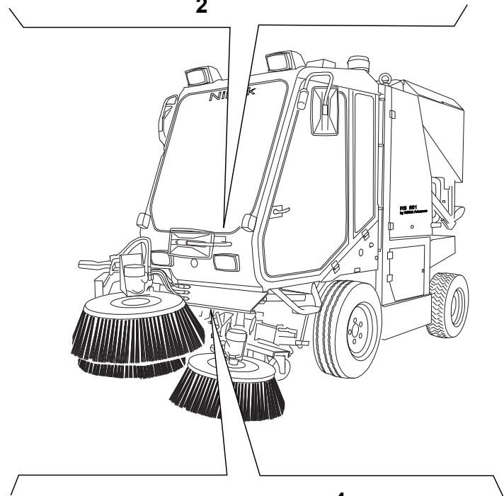
MACHINE DESCRIPTION
This sweeper has been designed and built to be used by a qualified operator to clean (by sweeping and suctioning) roads, smooth and solid floors, in civil and industrial environments, and to collect dust and light debris under safe operation conditions.
CONVENTIONS
Forward, backward, front, rear, left or right are intended with reference to the operator's position, while on the driver's seat (14, Fig. E).
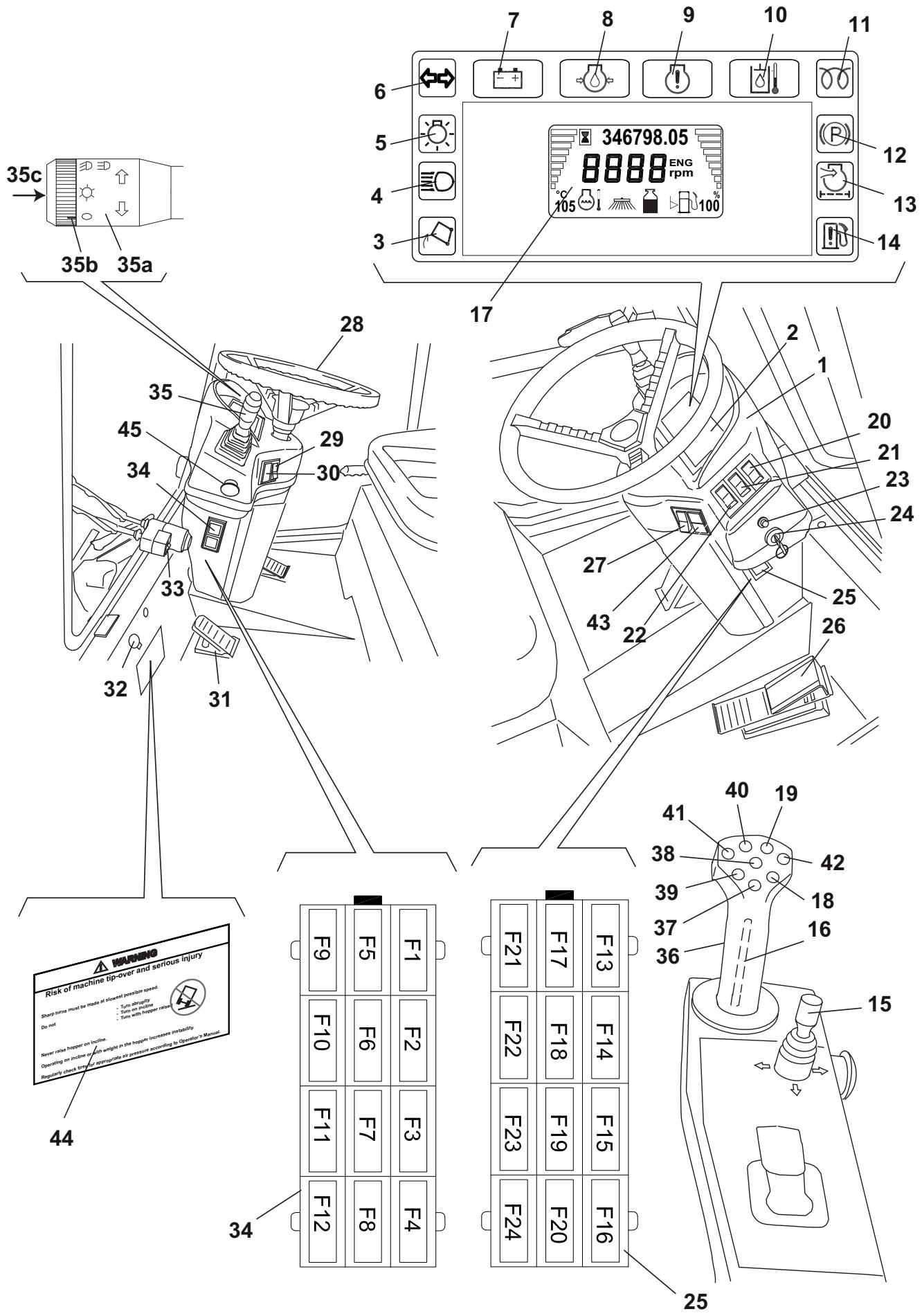
DESCRIPTION
Description of the control area
(See Fig. D)
- Meter and control panel
- Meter
- Lifted hopper warning light
- High beam indicator light
- Running light indicator light
- Turn signal indicator light
- Battery warning light
- Engine oil pressure warning light
- Check engine warning light (high temperature)
- Hydraulic system oil high temperature and hydraulic system fault warning light
- Glow plug pre-heating warning light
- Parking brake warning light
- Clogged engine air filter warning light
- Water-in-fuel warning light
- 3rd broom joystick (*), to activate the following functions (after pressing the 3rd broom switch):
Forward: 3rd broom lowering
- Backward: 3rd broom lifting
Right side: arm to the right side
- Left side: arm to the left side
- Safety push-button (press and hold it to enable the other push Buttons on the joystick) (*)
- Display (^**)
- Hopper lowering push-button (*)
- Hopper lifting push-button (*)
- Hazard warning light switch
- Hopper door opening/closing switch
- Front skirt lifting switch
- Windscreen washer switch
- Ignition key
- Right fuse box
-
Drive pedal
-
Dust control system water pump switch:
-
When the switch is turned to the first position, the nozzles sprinkle a medium quantity of water
-
When the switch is turned to the second position, the nozzles sprinkle the maximum quantity of water
-
Steering wheel
- Side brooms (first position) and 3rd broom (second position) switch
- Upper/ lower headlight selector
- Brake pedal
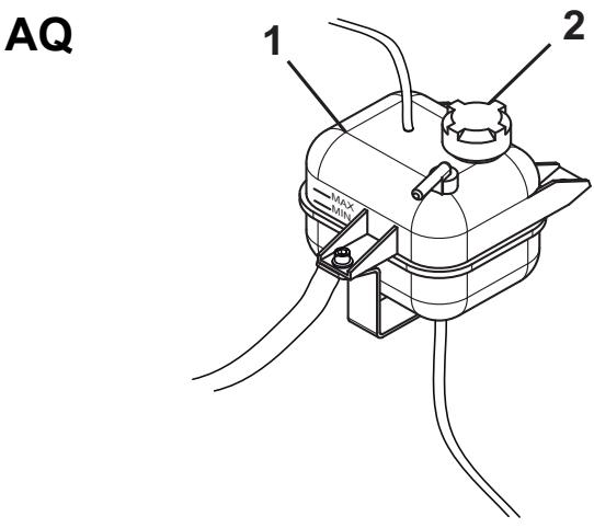
- Windscreen wiper fluid tank
- Windscreen wiper switch
- Left fuse box
- Combination switch (***)
- Suction inlet, brooms, hopper joystick (^*)
- Suction inlet and side broom lowering push-button (*)
- Suction inlet and side broom lifting push-button (*)
- Hopper return push-button (*)
- Hopper dumping push-button (*)
- Suction inlet and side broom left shifting push-button (*)
- Suction inlet and side broom right shifting push-button (*)
- Display scroll button
- Warning decal
- Emergency stop push-button
() In the machines with left-hand drive, these components are on the left door of the cab.
(^) See the display functions below.
(^*) See the combination switch functions below.
Display functions:
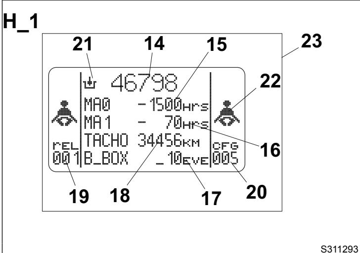
1. When the key is turned to ON
When the ignition key (24, Fig. D) is turned to the first position, the display (17) shows for a few seconds the first page (23, Fig. H) with numbers or symbols that indicate the machine condition. The parameters that can be checked are shown below.
Scheduled maintenance intervals.
MA0 (15, Fig. H) indicates the scheduled maintenance at 150 hours, while MA1 (16) indicates the scheduled maintenance at 500 hours. If one of the intervals is nearly expired or expired (negative number), maintenance procedures must be performed as shown in the relevant chapter.

NOTE
When one of the maintenance intervals has expired, one of the symbols (15 or 16, Fig. H) flashes for a few seconds at machine start-up.
- Enabled hydraulic system (21, Fig. H).

WARNING!
If the symbol is not shown, but the key appears on the display, it means that the maintenance interval has expired. Proceed as shown in the relevant chapter.
Number of working hours (14, Fig. H).
- Odometer (18, Fig. H).
- Alarm counter (17, Fig. H). It counts the number of alarms occurred after the last reset of the control unit. If the number is different from zero, contact a Nilfisk Service Center to reset the system.
- Software overhaul (19, Fig. H).
- Road sweeper identification number (20, Fig. H). The number "005" identifies the RS 851 model, with VM D703 IE3 engine.
- Fasten the seat belts. The flashing symbols (22, Fig. H) warns that the seat belts must be fastened.
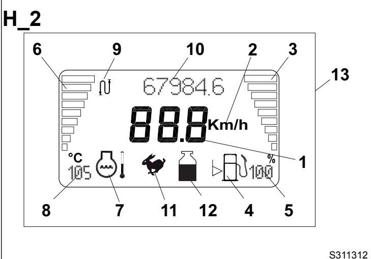
2. Transport mode visualisation
When the key is turned to ON, the display (17, Fig. D) automatically shows the transport mode visualisation (13, Fig. H) thus replacing the screen (23). The screen (13, Fig. H) remains even after the engine has been turned on. This screen shows the following parameters.
Machine speed: 3-digit number (1, Fig. H) with the following symbol Km/h (2).

WARNING!
The speedometer sensor cannot be checked for efficiency, so the system detects that the machine is stopped even if the sensor is disconnected or shorted, so the related safety systems are disabled.
- Fuel level: the fuel level is shown by the horizontal bar indicator (3, Fig. H). The last bars indicate the reserve, they flash when the level is low. The fuel level instantaneous value in % (5, Fig. H) is shown too.

CAUTION!
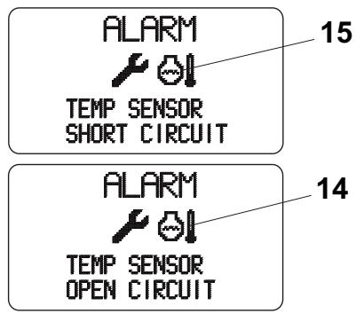
If the level sensor is faulty, the display shows warning messages according to the type of fault (short or open circuit) (for the alarm coding see the Alarm Description paragraph). To repair the circuit and replace the level sensor, contact a Nilfisk Service Center.
The symbol (4, Fig. H) indicates that the fuel level indicator is activated.
- Engine coolant temperature: the temperature level is shown by the horizontal bar indicator (6, Fig. H). The bars flashes in case of overheating. The temperature instantaneous value (8, Fig. H) is shown too. The symbol (7, Fig. H) indicates that the temperature indicator is activated.

CAUTION!
If the temperature sensor is faulty, the display shows warning messages according to the type of fault (short or open circuit) (for the alarm coding see the Alarm Description paragraph). To repair the circuit and replace the temperature sensor, contact a Nilfisk Service Center.
-
Dust control system tank water level with the relevant indicator (12, Fig. H):
-
main tank and sub-tank are full
- main tank is empty and sub-tank is full
- main tank and sub-tank are empty. In this condition, the dust control system and high-pressure washing system turn off after about 5 seconds.
the level sensors are faulty or exchanged.
Machine operation mode with the relevant indicator (11, Fig. H):
- transport mode
Total kilometres travelled (10, Fig. H) with the relevant symbol (9).

WARNING!
If the symbol is not shown, but the key appears on the display, it means that the maintenance interval has expired. Proceed as shown in the relevant chapter.

WARNING!
If the symbol shown is not the specified one but the warning symbol! appears, it means that some alarms are stored in the B_BOX. Check the B_BOX (as shown in the relevant paragraph) and send the stored alarm codes to a Nilfisk Service Center to reset the alarms.
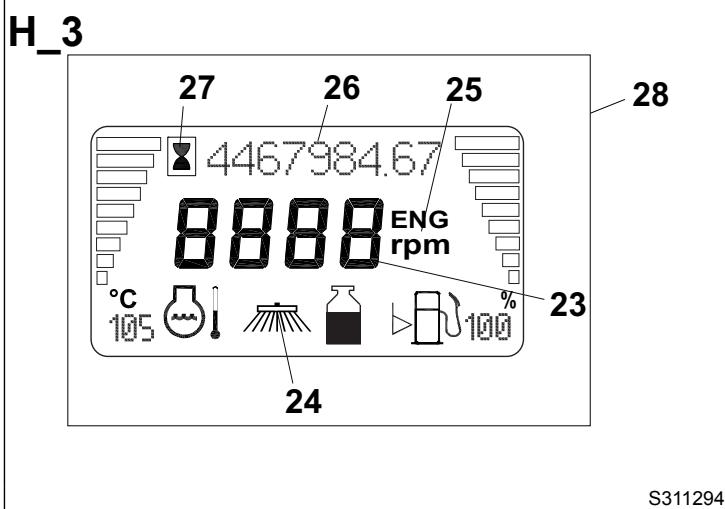
3. Working mode visualisation
When the engine is running, if the machine is set to working mode with the brooms turned on (see the procedure in the relevant paragraph), the display (17, Fig. D) shows the working mode (28, Fig. H) which contains the following parameters. Only the parameters different from transport mode are shown.
- Engine speed: 4-digit number (23, Fig. H) with the following symbol [ENG] (25).
Machine operation mode with the relevant indicator (24, Fig. H): working mode - Engine operation hours (26, Fig. H) with the relevant symbol (27).

WARNING!
If the symbol is not shown, but the key appears on the display, it means that the maintenance interval has expired. Proceed as shown in the relevant chapter.

WARNING!
If the symbol shown is not the specified
one but the warning symbol !
appears, it means that some alarms are stored in the B_BOX. Check the B_BOX (as shown in the relevant paragraph) and send the stored alarm codes to a Nilfisk Service Center to reset the alarms.
4. Alarm visualisation
When the engine is running, in case of machine malfunctions, the alarms will be shown on the display (17, Fig. D).
These alarms are shown in the visualisation (11, Fig. I). To fully understand the alarms, see the Alarm Description paragraph.
5. Machine memory visualisation

CAUTION!
This reading and/or check must be performed with the machine stopped, in order not to distract attention from driving.
When the key is turned to ON and the machine is stopped, it is possible to check the data about the machine condition by performing:
-
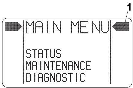
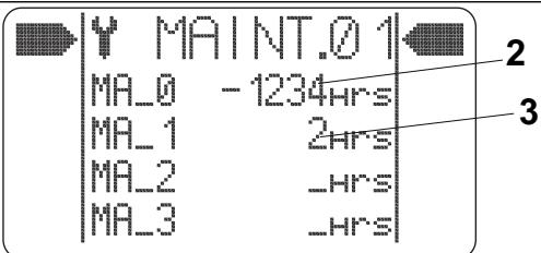
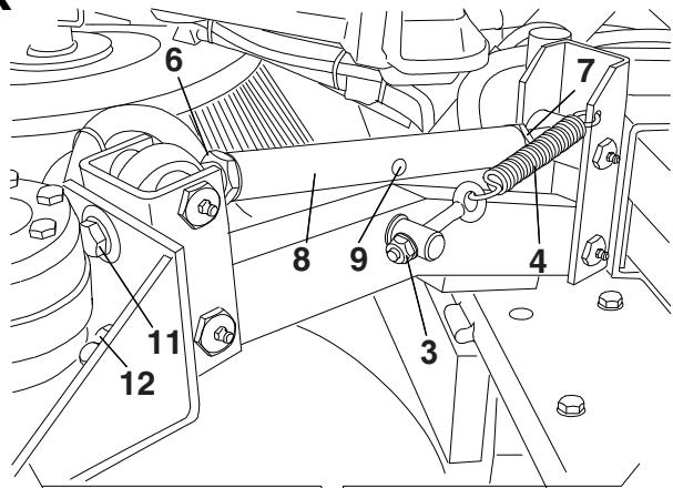
Consultation of maintenance intervals, in "MAIN MENU" on the display (17, Fig. D). To do this, repeatedly press the upper part of the push-button (15, Fig. D) until the above-mentioned item appears. Confirm by pressing the lower part of the push-button (15, Fig. D). The arrow cursor (1, Fig. J) will be placed near the word "STATUS". Press the lower part of the push-button (15, Fig. D) again to bring the arrow cursor near the word "MAINTENANCE". Confirm by pressing the upper part of the push-button (15, Fig. D). On the display (17, Fig. D) the page "MAINT.01" will be displayed. The number of hours (2, Fig. J) indicates how many hours there are before maintenance MA_0 will expire (150 hours), while the number of hours (3) indicates how many hours there are before maintenance MA_1 will expire (500 hours). By pressing the upper part of the push-button (15, Fig. D) again, the display (17) will show the page "MAINT.02". The number of hours (4, Fig. J) indicates the diesel engine running hours, the number of hours (5) indicates the machine working hours, the number of km (6) indicates the total number of km travelled by the machine, while the number (7) indicates the alarms occurred after the last system reset.
-
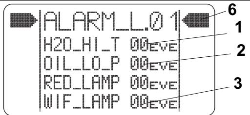
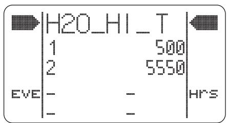
Consultation of ALARM LIST, in "MAIN MENU" on the display (17, Fig. D). To do this, repeatedly press the upper part of the push-button (15, Fig. D) until the above-mentioned item appears. Confirm by pressing the lower part of the push-button (15, Fig. D). The arrow cursor (6, Fig. J) will be placed near the word "STATUS". Press the lower part of the push-button (15, Fig. D) again to bring the arrow cursor near the word "DIAGNOSTIC". Confirm by pressing the upper part of the push-button (15, Fig. D). On the display (17, Fig. D) the page "ALARM_L.01" is shown. By pressing the upper part of the push-button (15, Fig. D) again, the page "ALARM_L.02" will be shown. These two pages contain the alarms shown in Alarm Description paragraph. The numbers (1, 2, 3 and 5, Fig. K) indicate how many times the alarm occurred. The alarm (4, Fig. K) indicates how many hours have passed since the clogged filter has been detected. If one of these numbers is different from zero, it is possible to check when the malfunction occurred. Press the lower part of the push-button (15, Fig. D) until the arrow cursor (6, Fig. K) is placed near the required data. By pressing the upper part of the push-button (15, Fig. D) again, the page of the required alarm will be shown. For example, Fig. L shows the "engine coolant overtemperature" alarm occurred for the first time after 500 hours, and the second time after 5,550 hours.
-
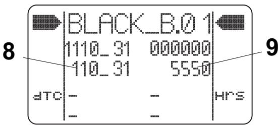
Consultation of B_BOX (7, Fig. J), where all the alarms occurred after the last memory reset are stored. The alarm is identified by a number code that can be displayed as shown below: repeatedly press the upper part of the push-button (15, Fig. D) until "MAIN MENU" appears. Confirm by pressing the lower part of the push-button (15, Fig. D). The arrow cursor (6, Fig. J) will be placed near the word "STATUS". Press the lower part of the push-button (15, Fig. D) again to bring the arrow cursor near the word "MAINTENANCE". Confirm by pressing the upper part of the push-button (15, Fig. D). On the display (17) the page "MAINT.01" is shown; when pressing the upper part of the push-button (15) again, the page "MAINT.02" is shown. When pressing the lower part of the push-button (15, Fig. D), the cursor aligns with B_BOX, then enter the B_BOX by pressing the upper part of the push-button (15). In this page, the first series of numbers (8, Fig. J) indicates the alarm identification number, while the second series of numbers (9) indicates the time at which the alarm occurred. The stored alarms are up to 16 displayed on four pages, which can be scrolled by pressing the push-button (15, Fig. D) repeatedly.

CAUTION!
In the B_BOX the alarms are stored one after the other, so when the alarms are detected, always check for the time at which the alarm occurred to have a real chronology of the alarms.
Combination switch functions:
- Headlights off, with mark (35b) at the symbol O
Running lights on, with mark (35b) at the symbol - Low beam on, with mark (35b) at the symbol 10 . When the combination switch is in this position, the working light turns on too.
High beam on, with mark (35b) at the symbol and lowered lever (35a)
High beam temporary on, lifting the lever (35a) - Right turn signal on, bringing the lever (35a) forward
- Left turn signal on, bringing the lever (35a) backward
- Horn activation, pushing the lever (35a) in the direction shown by the arrow (35c)
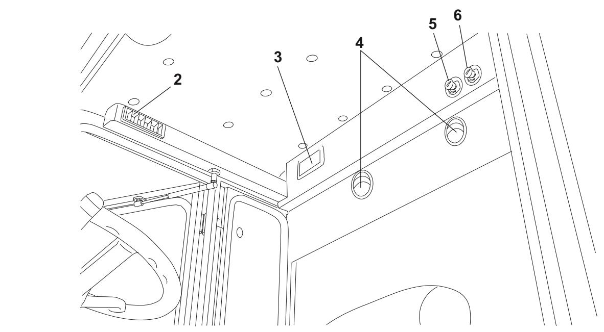
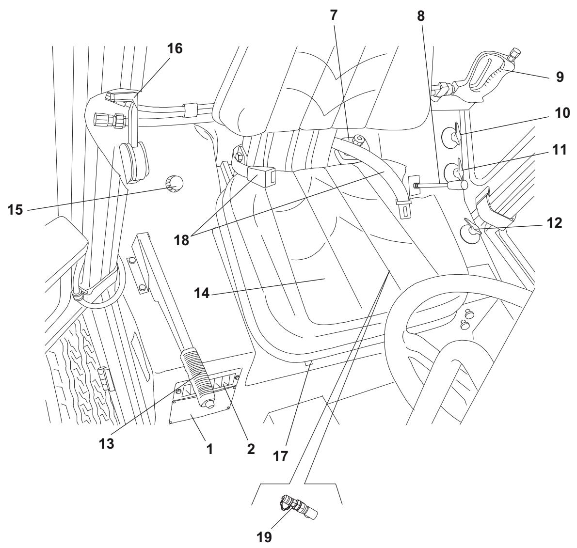
(See Fig. E)
- Serial number plate/technical data/conformity certification
- Cab vents
- Ceiling light
- Cab air recirculation vents
- Climate control knob
- Cab air flow control knob
- Brake fluid tank (^**)
- Suction fan/optional equipment lever
- High-pressure water gun
-
Dust control system nozzle valve:
-
Suction hose (from suction inlet to hopper)
Rear suction pipe (^*) -
Side broom dust control system nozzle valve
- 3rd broom dust control system nozzle valve
- Parking brake lever
- Driver's seat
- Cab heater control knob
- Diesel engine throttle lever
- Driver's seat forward/backward adjustment lever
- Driver's seat safety belt
- Emergency stop push-button
- Accessory distributor pressure inlet
(*) Optional
(**) In the machines with right-hand drive, these components are on the right side of the driver's seat.
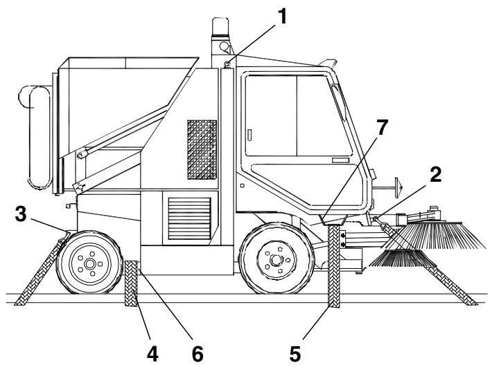
Outside view
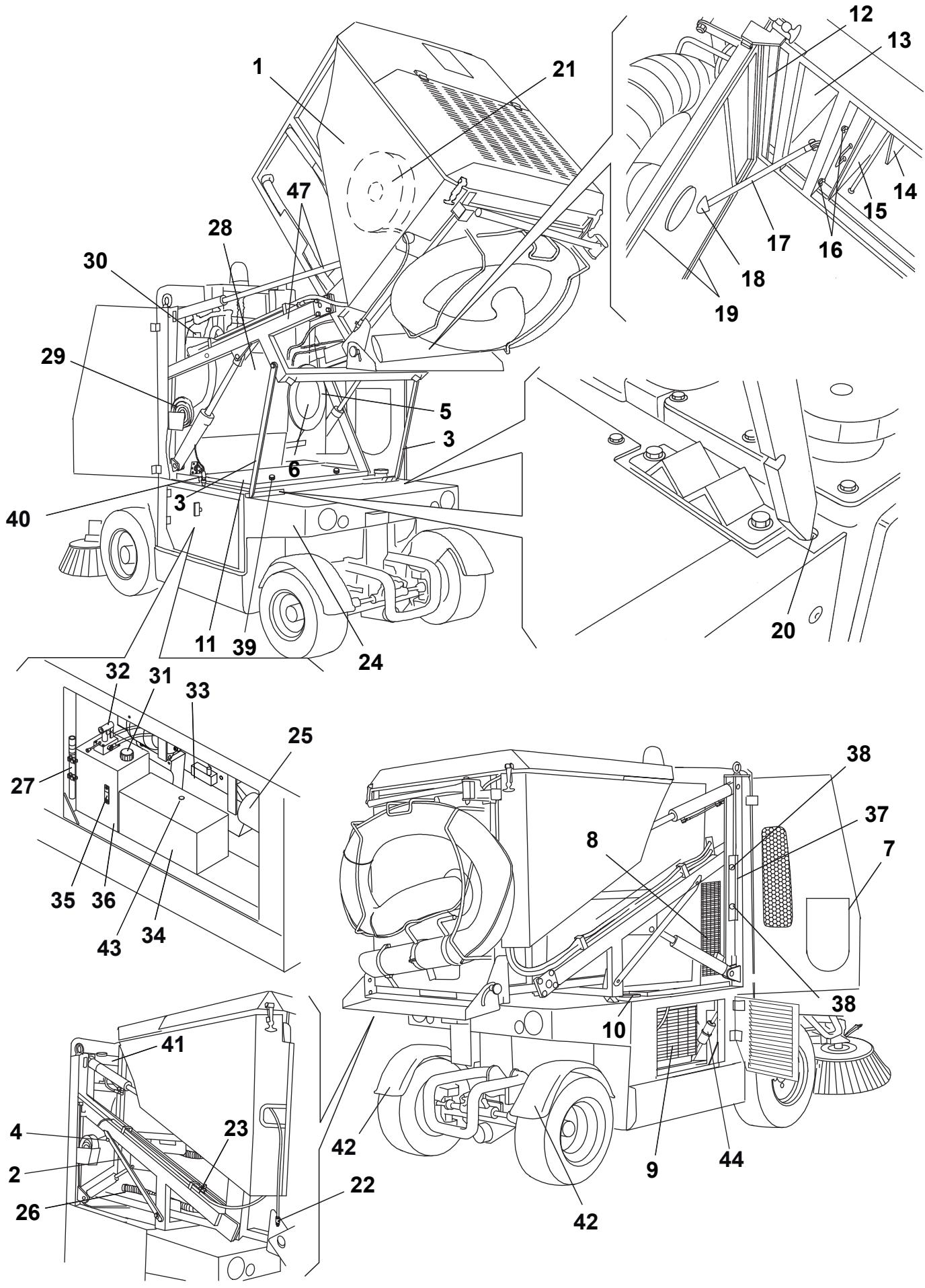
(See Fig. F)
1. Lifted and dumped hopper
2. Lifted hopper support rods (not applied)
3. Lifted hopper support rods (applied)
4. Lifted hopper support rod fasteners (not applied)
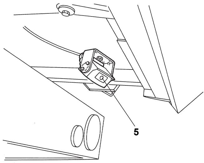
5. Suction hose gasket
6. Suction hose (from suction inlet to hopper)
7. Hopper front suction hole cover
8. Cab climate control condenser
9. Hydraulic system oil cooler
10. Fuel tank filler neck
11. Engine compartment panel
12. Inlet air breather filter
13. Suction fan compartment
14. Debris deflector
15. Dust and debris suction filter
16. Suction filter fasteners
17. Hopper door (open) support rod
18. Hopper door support rod housing
19. Suction sealing gasket
20. Hopper support rod housing
21. High-pressure washing system hose with reel
22. High-pressure water quick coupling
23. Rear suction pipe dust control system nozzles valve
24. Dust control system sub-tank
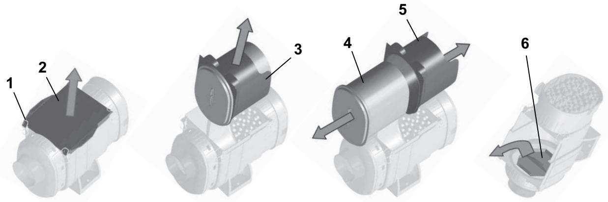
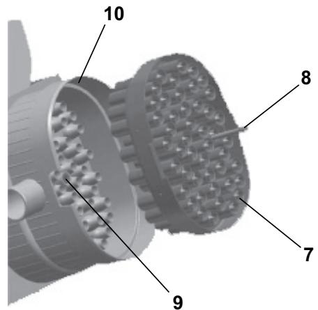
25. Engine air filter
26. Hopper water drain hose
27. Hopper manual lifting hand pump lever
28. Dust control system main tank
29. Dust control system water supply hose
30. Dust control system main tank plug
31. Filler plug
32. Hopper manual lifting hand pump
33. Diesel engine (for a description of the diesel engine components, refer to the relevant Manual)
34. Battery
35. Hydraulic system oil level indicator
36. Hydraulic system oil tank
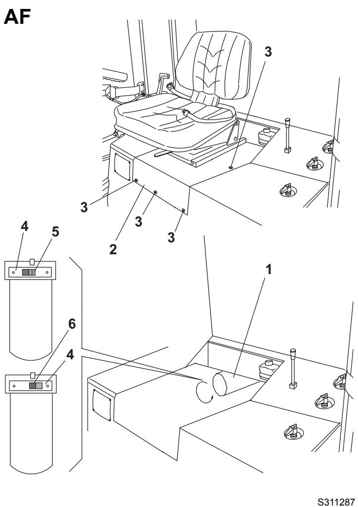
37. Front wheel lifting bracket
38. Bracket mounting knobs
39. Mounting knob
40. High-pressure water gun nozzle hose
41. Expansion tank
42. Fenders (*)
43. Battery hygrometer
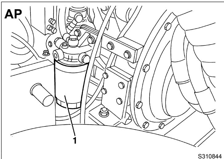
44. Fuel pre-filter
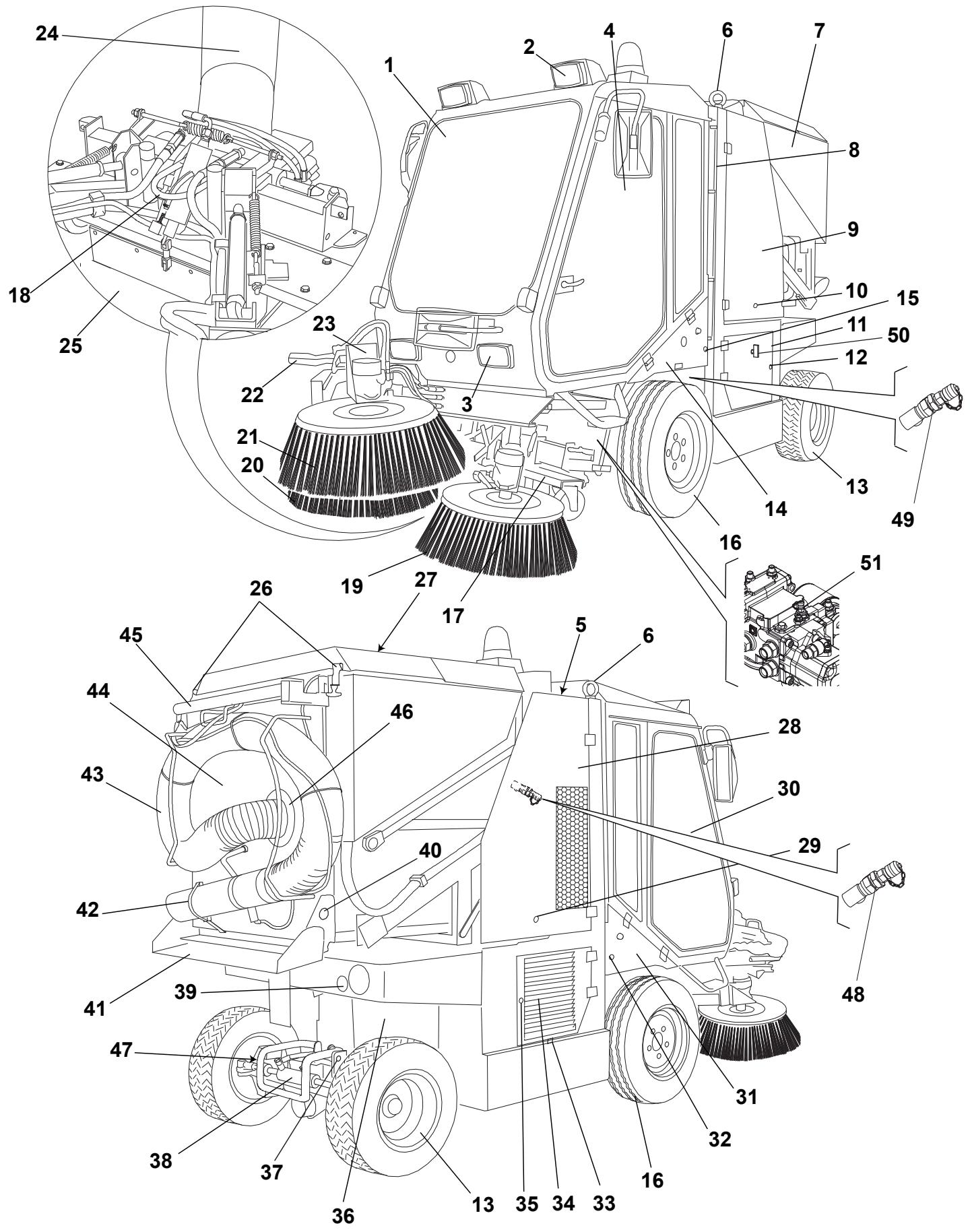
(See Fig. G)
- Cab
- Headlights (upper)
- Headlights (lower)
- Cab left door
- Engine coolant tank
- Machine lifting hooks (to be used only when the hopper is empty)
- Hopper
- Dust control system water level indicator
- Left side upper door
- Door fastener
- Left side lower door
- Door fastener
- Rear steering wheels
- Left under-cab door
- Door fastener
- Front driving wheels (fixed)
- Suction inlet
- Front towing hook
- Left broom
- Right broom
- 3rd broom (*)
- 3rd broom safety arm for machine transport (disengaged)
- 3rd broom arm
- Suction hose (from suction inlet to hopper)
- Front skirt
- Inlet air breather filter hood fasteners
- Inlet air breather filter hood
- Right side upper door
- Door fastener
- Cab right door
- Right under-cab door
- Door fastener
- Machine serial number
- Right side lower door
- Door fastener
- Diesel engine
- Rear towing hook
- Rear steering axle
- Tail lights
- Rear shoote side mounting knob
- Rear dumping shoote (open)
- Rear suction pipe fastener
- Rear suction pipe (*)
- Hopper door
- Rear suction pipe support arm (engaged)
- Rear suction pipe cover
- Rear bumper (*)
- Suction fan pressure inlet
- 3rd broom pressure inlet
- Battery release device
- Drive system pump pressure inlet
(*) Optional
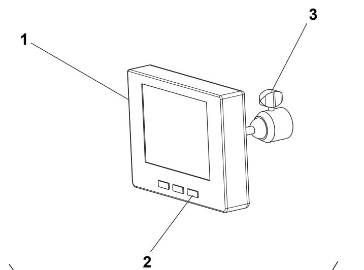
Camera kit description (optional)
(See Fig. AX)
- Display
- ON/OFF switch
- Video adjustment knobs
- Front camera
- Rear camera
TECHNICAL DATA
| Dimensions and weights | Values |
| Machine length | 142.9 in (3,630 mm) |
| Machine length with rear pipe | 150.8 in (3,830 mm) |
| Machine length with 3rd broom | 163.4 in (4,150 mm) |
| Machine length with 3rd broom and rear pipe | 171.1 in (4,350 mm) |
| Machine width | 53.1 in (1,350 mm) |
| Distance between front and rear wheels | 66.1 in (1,680 mm) |
| Front wheel base | 43.9 in (1,115 mm) |
| Rear wheel base | 44.9 in (1,140 mm) |
| Machine height with flashing light | 97.2 in (2,470 mm) |
| Machine height with rain cap on muffler | 92.9 in (2,360 mm) |
| Machine height with bend pipe on muffler | 92.9 in (2,360 mm) |
| Minimum distance from the ground (skirts not included) | 3.5 in (90 mm) |
| Maximum front working angle | 16° |
| Maximum dumping height | 63.8 in (1,620 mm) |
| Front tyres | 195 R 14C 106/104N (8 PR) |
| Rear tyres | 23x8.50-12 (10 PR) |
| Tyre pressure | 72.5 psi (5 Bar) |
| Left/right broom diameter | 25.6 in (650 mm) |
| Total machine weight, in running condition (without operator) | 6,019 lb (2,730 kg) |
| 3rd broom weight | 220.5 lb (100 kg) |
| Total mass | 8,267 lb (3,750 kg) |
| Machinehare weight | 5,181 lb (2,350 kg) |
| Machine weight for shipment | 5,291 lb (2,400 kg) |
| Performance data | Values |
| Maximum forward speed (for transport only) | 11.8 mph (19 km/h) |
| Maximum working speed | 7.4 mph (12 km/h) |
| Maximum reverse speed | 5.0 mph (8 km/h) |
| Gradeability at full load | 22% |
| Minimum inner turning radius | 132.9 in (3,375 mm) |
| Maximum side broom speed | 80 rpm |
| Collection system | Suction |
| Cleaning width with 2 brooms | 63.0 in (1,600 mm) |
| Cleaning width with 3 brooms | 82.7 in (2,100 mm) |
| Filtering system | Metallic net |
| Sound pressure level at workstation (ISO/EN3744) at maximum working speed | 81 dB(A) |
| Certified sound power (2000/14/EC) at maximum working speed | 109 dB(A) |
| Hopper capacity | 224.5 USgal (850 litres) |
| Hopper maximum load | 2,535 lb (1,150 kg) |
| Dust control system | By water |
| Dust control system tank total capacity (no. 2) | 60.7 USgal (230 litres) |
| Lighting and signalling system | Road type |
| Transmission | Hydrostatic servoassisted |
| Steering system | On the rear axle, power assisted |
| Brake | Hydraulic |
| Parking brake | Mechanic |
| Controls | Electrohydraulic |
| Diesel engine data (*) | Values |
| Make | VM MOTORI |
| Type | D703 IE3 87C/3 |
| Cylinders | 3 |
| Displacement | 127.0 in³ (2,082 cm³) |
| Maximum speed | 2,600 rpm |
| Maximum working speed | 2,050 rpm |
| Maximum power | 64.4 Hp (48 kW) |
| Idle speed | 1,000 rpm |
| Engine coolant | 50% of AGIP antifreeze and 50% of water |
| Antifreeze type | AGIP Antifreeze Extra (**) |
| Engine oil type | AGIP Sigma Super TFE 10W40 (*** ) |
| Engine oil pan capacity (maximum/minimum) | 12.0/10.0 lb (5.45/4.45 kg) |
| Consumption in running conditions during transport | 2.1 USgal/h (8 l/h) |
| Consumption in running conditions during operation | 1.8 USgal/h (6.7 l/h) |
() For other diesel engine data/values, see the relevant Manual.
(^) See the coolant technical data and reference data tables below.
(^*) See the engine oil technical data and reference data tables below.
| AGIP ANTIFREEZE EXTRA SPECIFICATIONS | ||
| Boiling point | °F (°C) | 338 (170) |
| Boiling point in solution with 50% water | °F (°C) | 230 (110) |
| Freezing point in solution with 50% water | °F (°C) | -36.4 (-38) |
| Colour | / | Turquoise blue |
| Density at +59 °F (+15 °C) | kg/l | 1.13 |
| Approvals and specifications |
| CUNA NC 956-16 97 |
| FF.SS cat. 002/132 |
| ASTM D 1384 |
| AGIP SIGMA SUPER TFE 10W40 SPECIFICATIONS | ||
| SAE QUALITY | / | 10W40 |
| Viscosity at +212 °F (+100 °C) | mm²/s | 14.5 |
| Viscosity at +104 °F (+40 °C) | mm²/s | 107 |
| Viscosity at -13 °F (-25 °C) | mm²/s | 6,400 |
| Viscosity index | / | 138 |
| Flash point COC | °F (°C) | 428 (220) |
| Pour point | °F (°C) | -16.6 (-27) |
| Density at +59 °F (+15 °C) | kg/l | 0.876 |
| Approvals and specifications |
| ACEA E4, E5, E7, B4 |
| APICH-4, CF/SL |
| MAN M 3277 + M 3277 low ash |
| Mercedes Benz 228.5 + 229.1 |
| MTU typ 3 |
| VW 505.00 level |
| RVI RXD |
| VOLVO VDS2 |
| CAT-TO 2 |
| ALLISON C-4 |
| ZF TE ML 04C |
| DEUTZ DQC IV 05 level |
| ISOTTA FRASCHINI |
| Refuelling data | Values |
| Fuel tank capacity | 17.2 USgal (65 litres) |
| Hydraulic system oil tank capacity | 14.5 USgal (55 litres) |
| Electrical system data | Values |
| System voltage | 12 V |
| Starting battery | 12 V – 100 Ah |
| Hydraulic system data | Values |
| Maximum drive system pressure | 4,351 psi (300 Bar) |
| Suction fan system maximum pressure | 3,046 psi (210 Bar) |
| Maximum accessory system pressure | 1,595 psi (110 Bar) |
| Hydraulic system oil viscosity [at ambient temperatures above +50 °F (+10 °C)] (*) | 46 cSt |
| Hydraulic system oil type | AGIP Arnica 46 (**) |
| Brake fluid type | DOT4 (*** ) |
() If the machine is to be used at ambient temperatures below +50^ (+10^) , the oil should be replaced with equivalent oil having a viscosity of 32 cSt. For temperatures below +32^ (0^) , use oil with lower viscosity.
(^) See the hydraulic system oil technical data and reference data tables below.
(^*) See the brake fluid technical data and reference data tables below.
| AGIP ARNICA SPECIFICATIONS | 46 | 32 | |
| Viscosity at +104 °F (+40 °C) | mm²/s | 45 | 32 |
| Viscosity at +212 °F (+100 °C) | mm²/s | 7.97 | 6.40 |
| Viscosity index | / | 150 | 157 |
| Flash point COC | °F (°C) | 419 (215) | 395.6 (202) |
| Pour point | °F (°C) | -32.8 (-36) | -32.8 (-36) |
| Density at +59 °F (+15 °C) | kg/l | 0.87 | 0.865 |
| Approvals and specifications |
| ISO-L-HV |
| ISO 11158 |
| AFNOR NF E 48603 HV |
| AISE 127 |
| ATOS Tab. P 002-0/I |
| BS 4231 HSE |
| CETOP RP 91 H HV |
| COMMERCIAL HYDRAULICS |
| Danieli Standard 0.000.001 (AGIP ARNICA 22, 46, 68) |
| EATON VICKERS I-286-S3 |
| EATON VICKERS M-2950 |
| DIN 51524 t.3 HVLP |
| LAMB LANDIS-CINCINNATI P68, P69, P70 |
| LINDE |
| PARKER HANNIFIN (DENISON) HF-0 |
| REXROTH RE 90220-1/11.02 |
| SAUER-DANFOSS 520L0463 |
| DOT4 SPECIFICATIONS | ||
| Viscosity at -40 °F (-40 °C) | mm²/s | 1,300 |
| Viscosity at +212 °F (+100 °C) | mm²/s | 2.2 |
| Dry boiling point | °F (°C) | 509 (265) |
| Wet boiling point | °F (°C) | 338 (170) |
| Density at +59 °F (+15 °C) | kg/l | 1.07 |
| Colour | / | Yellow |
| Approvals and specifications |
| SAE J 1703 |
| FMVSS 116 - DOT4&DOT3 |
| ISO 4925 |
| CUNA NC 956 DOT4 |
| Climate control system data | Values |
| Gas type | Reclin 134a |
| Gas quantity | 1.76 lb (0.8 kg) |
| Camera kit description (optional) (*) | Values (*) |
| Make | Continental VDO - |
| Type | LCD 5" colour monitor Infrared colour camera |
(*) For other data/values of the optional equipment, see the relevant Manuals.
ENVIRONMENTAL CONDITIONS
In the environment where the machine operates, there must not be any danger of explosion.
- To avoid inhaling exhaust gas, the machine must be used only where there is a proper ventilation.
- The machine operates properly (*) in the following environmental conditions:
Temperature: +14 °F to +104 °F (-10 °C to +40 °C)
Humidity: 30% to 95%
(*) When using the machine at ambient temperatures between +14^ and +32^ (-10 °C and 0 °C), the dust control system cannot be used; moreover the water tanks and the dust control system itself must be empty.
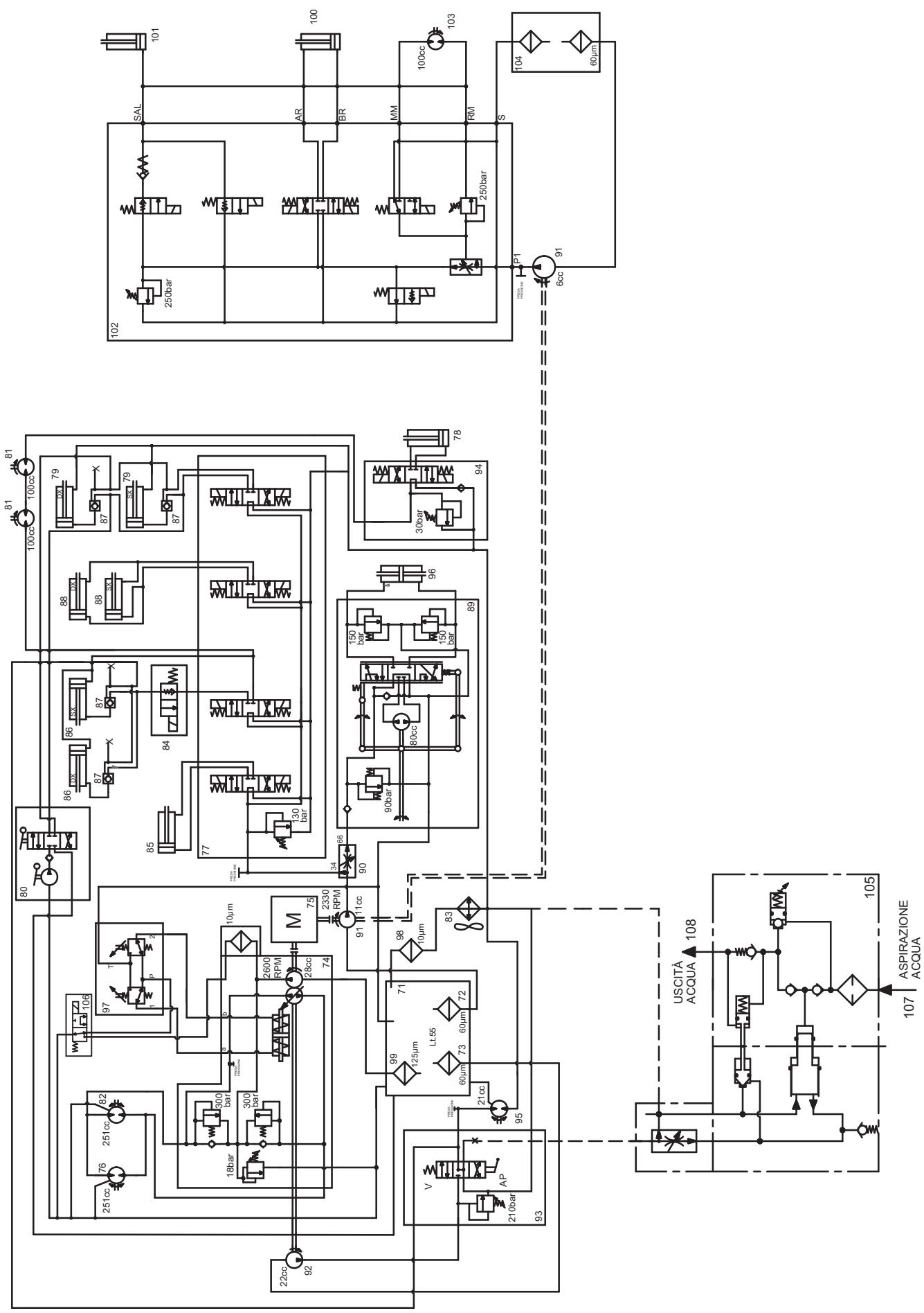
HYDRAULIC DIAGRAM
(See Fig. AW)
71. Hydraulic system oil tank
72. Drain filter
73. Suction filter
74. Drive system pump
75. Diesel engine
76. Drive system hydraulic motor
77. Accessory system distributor
78. Front skirt lifting cylinder
79. Hopper lifting cylinder
80. Hand pump
81. Side broom motor
82. Drive system hydraulic motor
83. Hydraulic system oil cooler
84. Solenoid valve
85. Suction inlet side shifting cylinder
86. Suction inlet lifting cylinder
87. Check valve
88. Hopper dumping cylinder
89. Power steering
90. Flow separator (priority valve)
91. Accessory and 3rd broom pump
92. Suction fan pump
93. Suction fan distributor
94. Front skirt distributor
95. Suction fan motor
96. Power steering cylinder
97. Drive pedal assist
98. Hydraulic system oil suction filter
99. Hydraulic system oil suction filter
100. 3rd broom arm rotation cylinder ()
101. 3rd broom lifting cylinder ()
102. Solenoid valve ()
103. 3rd broom motor ()
104. Hydraulic filter ()
105. High-pressure washing system pump ()
106. Forced idle gear solenoid valve
107. Water suction ()
108. Water outlet ()
(*) Optional
ELECTRICAL FUSES
At the right and left sides of the steering column there are two fuse boxes (25 and 34, Fig. D), with a transparent cover, containing the following fuses:
Fuse box A (34, Fig. D)
- Right side high beam fuse (15 A)
- Low beam fuse (15 A)
- Turn signal fuse (10 A)
- Brake light fuse (10 A)
- Right side running light fuse (7.5 A)
- Left side running light fuse (7.5 A)
- Flashing light fuse (7.5 A)
- Windscreen wiper motor fuse (7.5 A)
- Hazard warning lights (+30)/horn fuse (15 A)
- Glow plug control unit fuse (7.5 A)
- Fuel solenoid valve fuse (7.5 A)
- Condenser blower/ceiling light fuse (10 A)
Fuse box B (25, Fig. D)
- Door actuator power supply fuse (10 A)
- Meter power supply fuse (7.5 A)
- Broom motor solenoid valve/driver's seat microswitch fuse (10 A)
- Water pump fuse (15 A)
- Camera/speedometer sensor power supply fuse (7.5 a)
- Sensor power supply fuse (10 A)
- Accessory solenoid valves and neutral gear fuse (10 A)
- Compressor/cab electric fan fuse (20 A)
- Parking brake warning buzzer/water-in-fuel sensor fuse (10 A)
- Skirt solenoid valve fuse (7.5 A)
- Hopper microswitch fuse (7.5 A)
- Exchanger blower fuse (20 A)
ALARM DESCRIPTIONS

WARNING!
The alarms are shown for up to 5 seconds. Then the alarm is stored in the B_BOX (see the Display Function Description paragraph).
The alarms are shown also in the ALARM LIST (refer to ALARM.01 and ALARM.02 in Display Function Description paragraph).
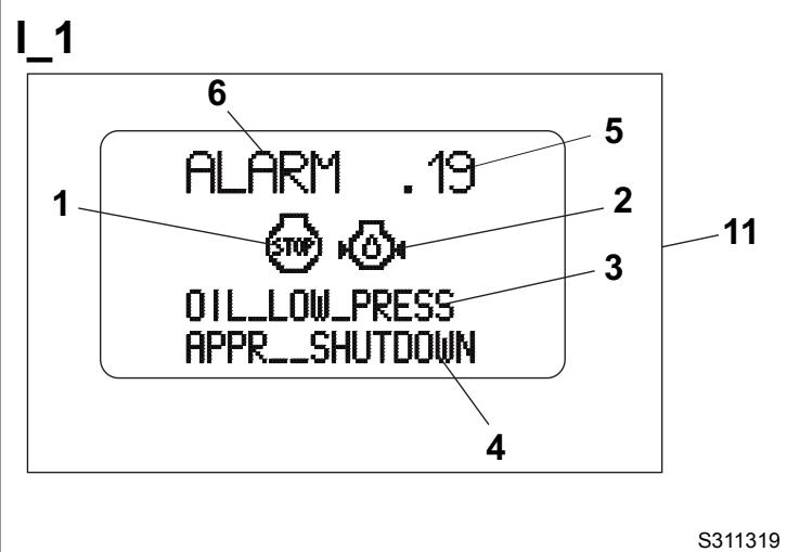
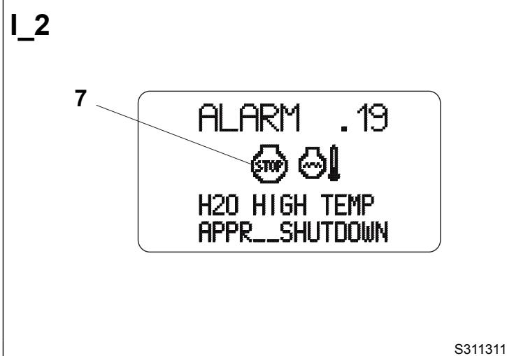
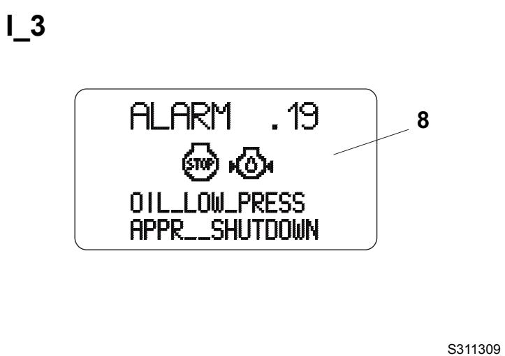
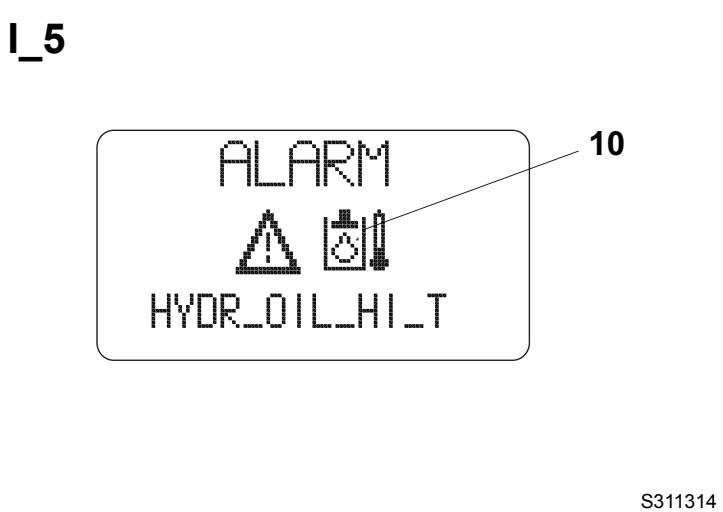
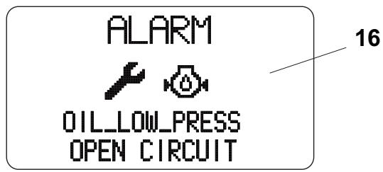
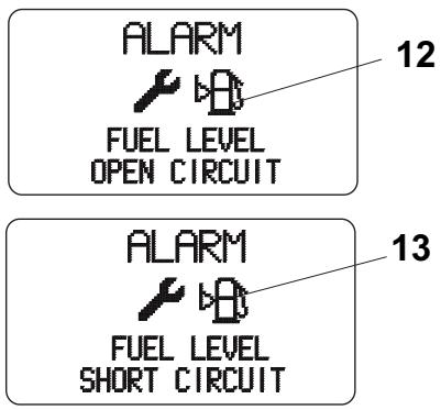
The alarms are indicated by the name "ALARM" (6, Fig. I) and by some symbols which identify the source (2) and the seriousness (1) of the alarm. The visualisation shown on the second line of the text identifies the alarm description (3, Fig. I). For some serious alarms, the machine will be automatically shutdown. In this case the counter (5, Fig. I) resets after a countdown of 20 seconds, then a message appears (4).
In the alarm indications, the seriousness symbol can be different:
- Alarm which does not compromise the machine operation. Check/replace the component which caused the alarm.
- Serious alarm which does not cause the machine shutdown. Contact a Nilfisk Service Center.
- Serious alarms which causes the machine shutdown. Contact a Nilfisk Service Center.
The alarms recognised and shown on the display (17, Fig. D) are shown below.
Shorted fuel level sensor (13, Fig. I)
- Open fuel level sensor (12, Fig. 1)
Engine coolant overtemperature (7, Fig. 1) (the engine is automatically shut-off)
Engine oil low pressure (8, Fig. 1) (the engine is automatically shut-off)
Water in fuel (9, Fig. 1)
Hydraulic oil overtemperature (10, Fig. 1)
- Open or disconnected engine coolant temperature sensor (14, Fig. I)
Shorted coolant temperature sensor (15, Fig. I)
- Open or disconnected engine oil pressure sensor (16, Fig. 1)
The above-mentioned alarms are also indicated by the activation of the relevant warning lights shown in Description of the Control Area paragraph.
ACCESSORIES/OPTIONS
In addition to the standard components, the machine can be equipped with the following accessories/options, according to the machine specific use:
- 3rd broom (^)(^)
Brooms with harder and softer bristles
Camera kit (^)
High-pressure washing system (^)(^)
Rear bumper
Rear fenders
Ready for radio installation
Cab climate control system (^)(^)
Rear suction pipe (^*)^() - Driver's seat safety belt (^*)
() Optional
(^*) In order to use these accessories, the sweeper must be equipped with the appropriate fittings.
USE

WARNING!
On some points of the machine there are some adhesive plates indicating:
DANGER
WARNING
- CAUTION
CONSULTATION
While reading this Manual, the operator must pay particular attention to the symbols shown on the plates.
Do not cover these plates for any reason and immediately replace them if they are damaged.
GENERAL CAUTIONS
This machine is designed as a high performance, high capacity sweeper that can clean in tight and congested areas.
By design this means a narrow wheel base with tight steering capability.
These design requirements can under certain conditions create instability during machine operation.
Instability can be caused by a combination of machine travel speed, abrupt manoeuvring, operation on an incline, low tyre pressure, weight in the hopper and or raised hopper.
For this reason the machine must be driven by a qualified operator who must be properly instructed on how to use it and be aware of the potential risks.
The following are situations known to cause instability in the machine and care should be taken by the operator to assure safe operation:
Lifting the hopper on an incline
- Manoeuvring the machine with the hopper lifted
Abrupt steering
- Manoeuvring with speed, on a slope and/or with weight in the hopper
Low tyre pressure
Inside the cab there is a decal (44, Fig. D) that warns the operator of the risk of instability and provides information on activities to avoid to prevent machine instability.
BEFORE START-UP
- If necessary, open the right upper door (28, Fig. G) by releasing the fastener (29) with the supplied key, and refuel the machine through the filler neck (10, Fig. F).

CAUTION!
Do not fill the fuel tank to the top, but leave at least 1.6 in (4 cm) from the filler neck to allow the fuel to expand.
Check the dust control system water level through the indicator (8, Fig. G).
If necessary, supply water according to the following procedure:
- Disengage the fastener (10, Fig. G) with the supplied key, then open the left door (9).
- Pour the water in the tanks through the plug (30, Fig. F), or the hose (29).
- Close the plug (30), or roll up the hose (29) and place it back in its housing.
-
Close the door (9, Fig. G) and secure it with the fastener (10) by using the supplied key.
-
Check that there are no open doors/hoods and that the machine is in normal operating conditions.
DIESEL ENGINE START AND STOP
Diesel engine start
- Insert the battery by turning the key of the release device (50, Fig. G) to horizontal position.
- Sit on the driver's seat (14, Fig. E) and check that the parking brake (13) is engaged.

NOTE
The machine is equipped with a safety system that does not allow for engine start up when the operator is not on the driver's seat (14, Fig. E).
- Check that the emergency push-button (19, Fig. E) is not activated.
- With the lever (17, Fig. E), adjust the seat for a comfortable position.
- Fasten the seat belts (18, Fig. E).

CAUTION!
For the operator's safety, the seat belts must always be fastened.
- Turn the engine throttle lever (16, Fig. E) to idle.
- Check that the brooms are lifted, otherwise check that the broom switch is not pressed to avoid any inconvenience caused by broom immediate activation at engine start-up.
- Check that the machine is in neutral [drive pedal (26, Fig. D) not pressed].

NOTE
The machine is equipped with a safety system that does not allow for engine start up when the drive pedal (26, Fig. D) is pressed.
- Insert the ignition key (24, Fig. D), turn it clockwise and hold it in the first position. On the warning light panel (2, Fig. D) the following warning lights turn on:
Diesel engine glow plug pre-heating warning light (11, Fig. D)
- Charged battery indicator light (7, Fig. D)
Engine oil pressure warning light (8, Fig. D)
- Parking brake warning light (12, Fig. D)
On the display (17, Fig. D) the first page is shown. To know the display options and information, see Display Functions paragraph.
When the glow plug pre-heating warning light (11, Fig. D) turns off, turn the ignition key clockwise, to the end of stroke, and then release it when the diesel engine starts.

CAUTION!
Preheating times must be respected especially in harsh climate areas, to avoid excessive smoke.

CAUTION!
When starting the diesel engine, do not keep the ignition key in cranking position too long (maximum 15 seconds) to avoid damaging the starter. If the engine does not start, wait a minute before trying again. Before trying to start the engine again, turn the ignition key counterclockwise, to the initial position. If the engine does not start after two attempts, do not persist, ask for help from the person responsible for the machine.
- Make sure that all the warning lights are off when the engine is running.
- With the throttle lever (16, Fig. E) in an intermediate position, let the engine run for a few minutes to allow it to warm up, especially when the air temperature is low.
Diesel engine stop
- Turn the engine throttle lever (16, Fig. E) to idle, and hold it in this position for a few minutes to let the system stabilize.
- Turn the ignition key (24, Fig. D) counterclockwise, to the end of stroke, then remove it.
- Engage the parking brake with the lever (13, Fig. E).
STARTING AND STOPPING THE MACHINE
The machine can be started and set to:
Transport mode
Working mode
The relevant procedures are shown below.

WARNING!
When steering, avoid abrupt direction changes, pay careful attention and drive the machine at slow speed, especially when the hopper is full or when operating on inclines.

CAUTION!
Before operating the machine, check that the tyre pressure is correct (72.5 psi [5 bar]) and, if necessary, adjust it.
Setting the machine to transport mode

CAUTION!
Before setting the machine to transport mode, check that alarms or expired maintenance intervals are not shown on the display (17, Fig. D) (see Display Functions paragraph).
To transport the machine (without sweeping), it is necessary to set the transfer mode according to the following procedure:
- Check that the parking brake (13, Fig. E) is engaged.
- Start the engine as shown in the previous paragraph.
- Check that the hopper (7, Fig. G) is lowered and that the warning light (3, Fig. D) is off.

CAUTION!
If the machine speed exceeds 3 mph (5 km/h) with the hopper lifted, the warning light (3, Fig. D) flashes to warn about the dangerous manoeuvre.
- Check that the suction fan is off; the lever (8, Fig. E) must be in central position.
- Lift the suction inlet and side brooms by pressing the push-button (38, Fig. D).
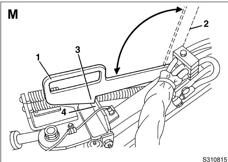
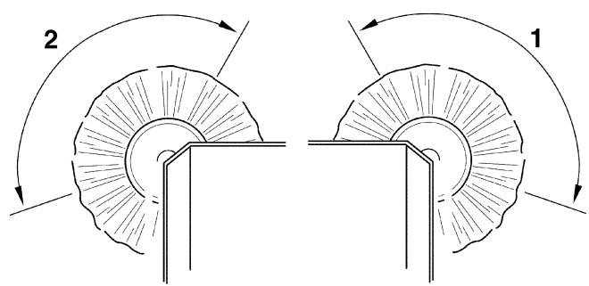
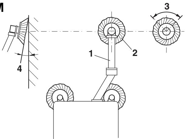
- Get out of the machine and bring the 3rd broom safety arm from the position (2, Fig. M) (disengaged) to the position (1) (engaged), by engaging the tooth (3) on the bracket (4).
- Sit on the driver's seat (14, Fig. E) and disengage the parking brake (13).

NOTE
The machine is equipped with a safety system that does not allow for engine start up when the operator is not on the driver's seat (14, Fig. E).
- Gradually bring forward the engine throttle lever (16, Fig. E) and set the engine speed on the display (17, Fig. D) to 2,600 rpm.
- Start to transport the machine, by keeping the hands on the steering wheel (28, Fig. D) and gradually pressing the pedal (26), on the front side to move forward and on the rear side to move backward.
The drive speed can be adjusted from zero to maximum speed by increasing the pressure on the pedal.

WARNING!
The machine is equipped with a safety system that stops the movement (machine in neutral) and disables the hydraulic functions controlled by the joysticks (15 and 36, Fig. D) when the operator is not on the driver's seat (14, Fig. E) for more than 3 seconds. The movement and the hydraulic functions restarts automatically when the operator returns on the driver's seat (14). Only the suction fan for the manual rear pipe, and the high-pressure pump for the washing system can be used in these conditions.

WARNING!
Remind that the steering is on the rear axle. Use rearview mirrors to see rear end of machine when manoeuvring.

WARNING!
In case of obstacles (for example a footpath), remind to lift the suction inlet.
Stopping the machine in transport mode
- To stop the machine release the pedal (26, Fig. D).
- To stop the machine quickly, press also the brake pedal (31).
- Turn the engine throttle lever (16, Fig. E) to idle, and hold it in this position for a few minutes to let the system stabilize.
- Turn off the engine, by turning the ignition key (24, Fig. D) counterclockwise, to the end of stroke, then remove it.
- Engage the parking brake with the lever (13, Fig. E).
Setting the machine to working mode

CAUTION!
Before setting the machine to working mode, check that alarms or expired maintenance intervals are not shown on the display (17, Fig. D) (see Display Functions paragraph).
Set the machine to working mode according to the following procedure:
- Start the engine as shown in the relevant paragraph.
- Check that the hopper (7, Fig. G) is lowered and that the warning light (3, Fig. D) is off.
- Bring the 3rd broom safety arm from the position (1, Fig. M) (engaged) to the position (2) (disengaged).
-
Gradually bring forward the engine throttle lever (16, Fig. E) and set the engine speed on the display (17, Fig. D) to:
-
minimum 1,800 rpm
maximum 2,030 rpm

CAUTION!
If 2,050 rpm are exceeded when working, a safety system stops the accessory system and the rpm number (1, Fig. H) flashes to warn about the fault.
- Turn on the suction fan by bringing the lever (8, Fig. E) in upper position.
- Start the side broom rotation by turning the switch (29, Fig. D) to the first position, and the 3rd broom rotation by turning the switch (29) to the second position.

NOTE
If the water pump switch (27, Fig. D) is pressed, the water supply to the nozzles starts automatically.
- Lower the suction inlet and side brooms by pressing the push-button (37, Fig. D).

NOTE
Side brooms lower only if the suction fan is on.

CAUTION!
Do not leave the sweeper stationary with the suction inlet lowered and the brooms rotating.
- Shift the 3rd broom arm to working mode, by moving the joystick (15, Fig. D) to the right/left.
- Lower the 3rd broom by pushing the joystick (15, Fig. D) forward.
- Check and, if necessary, top up the dust control system water tanks, and check which symbol (12, Fig. H) turns on:
main tank and sub-tank are full
- main tank is empty and sub-tank is full
- main tank and sub-tank are empty. In this condition, the dust control system and high-pressure washing system turn off after about 5 seconds.
- failure in the dust control system tank water level detection or visualisation system. Contact a Nilfisk Service Center.
-
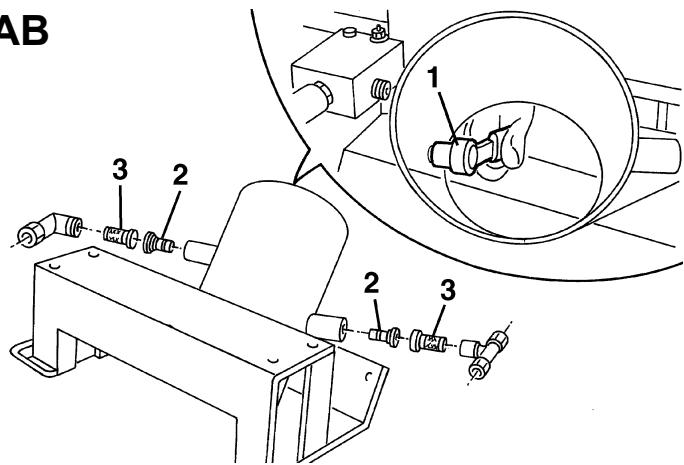
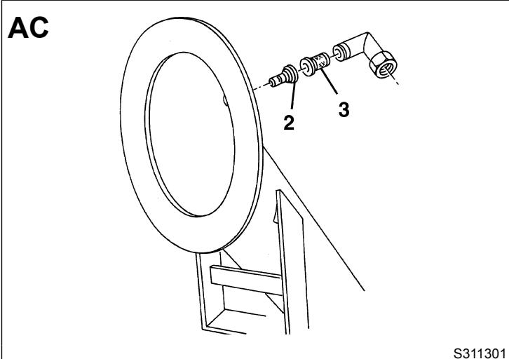
If necessary, open the dust control system valves (10, 11, 12, Fig. E), considering the following:
-
Suction pipe dust control system nozzle valve (10, Fig. E): Open it always, except when the floor to be cleaned is wet.
- This valve sends water also to the rear pipe dust control system nozzle (optional).
- Side broom dust control system nozzle valve (11, Fig. E): Open it when the floor is dry and dusty.
-
3rd broom dust control system nozzle valve (12, Fig. E): Open it when the floor is dry and dusty.
-
Turn on the dust control system water pump with the switch (27, Fig. D) according to the following procedure:
-
When the switch is turned to the first position, the nozzles sprinkle a medium quantity of water (use it when there is little dust)
- When the switch is turned to the second position, the nozzles sprinkle the maximum quantity of water (use it when there is a lot of dust)

CAUTION!
The machine is equipped with an automatic system that, when the operator is on the driver's seat (14, Fig. E) and the water pump switch (27, Fig. D) is pressed, allows for water supply to the nozzles only if the broom rotation is enabled.
If the operator is not on the driver's seat (14, Fig. E) to use the rear pipe, water can be supplied by the nozzles using the water pump switch (27, Fig. D) only.
- Disengage the parking brake with the lever (13, Fig. E).
- Start sweeping, by keeping the hands on the steering wheel (28, Fig. D) and gradually pressing the pedal (26), on the front side to move forward and on the rear side to move backward.
The drive speed can be adjusted from zero to maximum speed by increasing the pressure on the pedal.
While working, the machine picks up both light materials such as dust, paper, leaves, etc. and heavy materials such as stones, bottles, etc.

WARNING!
The machine is equipped with a safety system that stops the movement (machine in neutral) and disables the hydraulic functions controlled by the joysticks (15 and 36, Fig. D) when the operator is not on the driver's seat (14, Fig. E) for more than 3 seconds. The movement and the hydraulic functions restarts automatically when the operator returns on the driver's seat (14). Only the suction fan for the manual rear pipe, and the high-pressure pump for the washing system can be used in these conditions.

NOTE
All brooms (19, 20, 21, Fig. G) can be lifted or lowered when the machine is moving.
The brooms rotate even when they are lifted.
Stopping the machine in working mode
- To stop the machine release the pedal (26, Fig. D).
To stop the machine quickly, press also the brake pedal (31, Fig. D). - Engage the parking brake with the lever (13, Fig. E).
- Turn off the dust control system water pump with the switch (27, Fig. D).
- If open, close the dust control system valves (10, 11, 12, Fig. E).
- Lift the 3rd broom by pushing the joystick (15, Fig. D) rearward.
- If necessary, shift the 3rd broom arm to working mode, by moving the joystick (15, Fig. D) to left.
- Stop the 3rd broom and side broom rotation with the switch (29, Fig. D).

NOTE
The machine is equipped with an automatic switch that stops the water supply to the nozzles when the broom rotation has been stopped by pressing the switch (29, Fig. D) and the water supply has not been previously stopped by pressing the switch (27).
- Lift the suction inlet and side brooms by pressing the push-button (38, Fig. D).
- Turn off the suction fan by bringing back the lever (8, Fig. E) in central position.
- Turn the engine throttle lever (16, Fig. E) to idle, and hold it in this position for a few minutes to let the system stabilize.
- Check that the hopper (7, Fig. G) is lowered and that the warning light (3, Fig. D) is off.
- If necessary, bring the 3rd broom safety arm from the position (2, Fig. M) (disengaged) to the position (1) (engaged), by engaging the tooth (3) on the bracket (4).
- Turn off the engine, by turning the ignition key (24, Fig. D) counterclockwise, to the end of stroke, then remove it.
- Engage the parking brake with the lever (13, Fig. E).
MACHINE OPERATION
- Avoid stopping for a long time with the machine in the same position and the brooms rotating: this could create unwanted marks on the floor.
Suction inlet and side broom shifting
- When necessary, in working mode, shift the suction inlet and side brooms to the left or to the right by pressing the pushbuttons (41 or 42, Fig. D) together with the safety push-button (16).
3rd broom shifting
- When necessary, in working mode, shift the 3rd broom to the left or to the right by moving the joystick (15, Fig. D) to left or to the right.
Bulky debris collection
- To collect bulky debris, lift the front skirt (25, Fig. G) by pressing the switch (22, Fig. D).
Note that, while the skirt is lifted, the machine suction power decreases.
To lower the front skirt (25, Fig. G), press the switch (22, Fig. D) again.
-
If necessary, to collect bulky debris, it is also possible to remove the front skirt (25, Fig. G); remove it according to the following procedure:
-
Lift the side brooms, then stop the machine and turn off the engine.
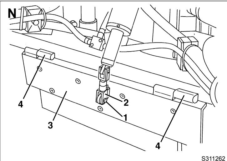
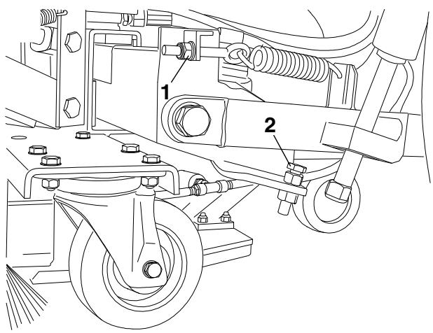
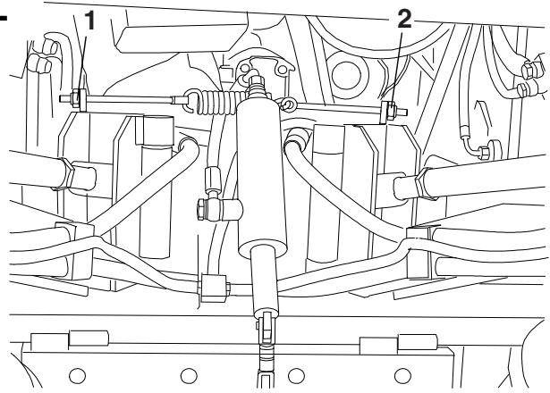
- Remove the clip (1, Fig. N) and disconnect the tie rod (2) from the skirt (3).
- Remove the skirt (3) by withdrawing it from the hinges (4).
- Turn on the machine and start working again.
Install the skirt (3) in the reverse order of removal, after stopping the machine and turning off the engine.

NOTE
When the hopper is full, the machine cannot collect dust and debris anymore.
- After each working cycle, and when the hopper (7, Fig. G) is full, it must be emptied. For the relevant procedure, see the next paragraph.
HOPPER DUMPING
The maximum hopper dumping height is 63.78 in (1,620 mm).
Dump the hopper according to the following procedure.
-
Turn off the dust control system water pump with the switch (27, Fig. D).
-
If open, close the dust control system valves (10, 11, 12, Fig. E).
-
Lift the 3rd broom by pushing the joystick (15, Fig. D) rearward.
-
Lift the suction inlet and side brooms by pressing the push-button (37, Fig. D).
-
Stop the 3rd broom and side broom rotation with the switch (29, Fig. D).
-
Turn off the suction fan with the lever (8, Fig. E).
-
If necessary, shift the 3rd broom arm to working mode, by moving the joystick (15, Fig. D) to left.
-
If the machine must be transferred to an appointed dumping area, engage the parking brake (13, Fig. E), get out of the machine and bring the 3rd broom safety arm from the position (2, Fig. M) (disengaged) to the position (1) (engaged), by engaging the tooth (3) on the bracket (4).
-
Drive the machine to the appointed dumping area.
-
If the hopper may contain a lot of water, it is possible to drain it before lifting and dumping the hopper according to the following procedure:
-
Engage the parking brake with the lever (13, Fig. E) and get out of the machine.
- Open the left upper door (9, Fig. G).
- Disengage the hose (26, Fig. F) and drain the water from the hopper.
Install the hose (26, Fig. F). - Close the left upper door (9, Fig. G).

WARNING!
Perform the hopper dumping on a solid and level ground, to avoid machine unbalance.
Keep people away from the machine and especially from the hopper (7, Fig. G).
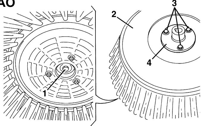
- Loosen the side knobs (1, Fig. O) and open the rear shooe by turning it from the position (2) to the position (3).
- Carefully lift the hopper (7, Fig. G), by pressing the push-button (19, Fig. D) and the safety push-button (16).

WARNING!
Do not move the machine when the hopper is lifted!
If machine movement with lifted hopper cannot be prevented, be sure to drive slowest possible speed to avoid lateral instability.
If the machine speed exceeds 3 mph (5 km/h) with the hopper lifted, the warning light (3, Fig. D) flashes to warn about the dangerous manoeuvre.
- Open the hopper door (44, Fig. G) with the switch (21, Fig. D); keep the switch pressed until the door is totally opened.
- Carefully dump the hopper (7, Fig. G), by pressing the push-button (40, Fig. D) and the safety push-button (16). Empty the hopper.
- When the dumping is completed, return the hopper to the horizontal position, by pressing the push-button (39, Fig. D) and the safety push-button (16).
- Lower the hopper (7, Fig. G) completely, by pressing the push-button (18, Fig. D) and the safety push-button (16). Keep the push Buttons pressed, until the warning light (3) turns off.
-
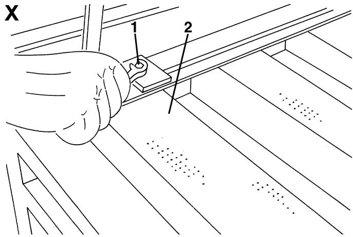
If necessary, check for hopper metal filter clogging, according to the following procedure:
-
Engage the parking brake and turn off the engine.
- Lift the hopper door manually and secure it with the support rod (17, Fig. F).
- As shown in the Maintenance chapter, remove the filters (15 and 12, Fig. F) and check for clogging. If the filters are clogged, clean them according to the relevant procedure. Install the filters.
-
Disengage the support rod (17, Fig. F) and place it in its housing.
-
Start the engine and close the hopper door (44, Fig. G) with the switch (21, Fig. D); keep the switch pressed until the warning light turns off.
- The machine is ready to start working again.
USING THE REAR SUCTION PIPE (*)
(*) Optional
To collect dust/debris with the rear suction pipe (optional) (43, Fig. G), rather than the suction inlet (17, Fig. G), perform the following procedure.
-
Turn off the engine and engage the parking brake with the lever (13, Fig. E).
-
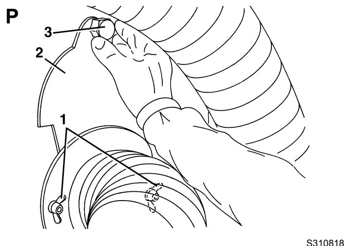
Loosen the suction pipe mounting knobs (1, Fig. P), then remove the suction hole cover (2) using the knob (3).
-
As shown in the Hopper Dumping paragraph, lift the hopper for 3.9-5.9 in (10-15 cm) approximately, then turn off the engine.
-
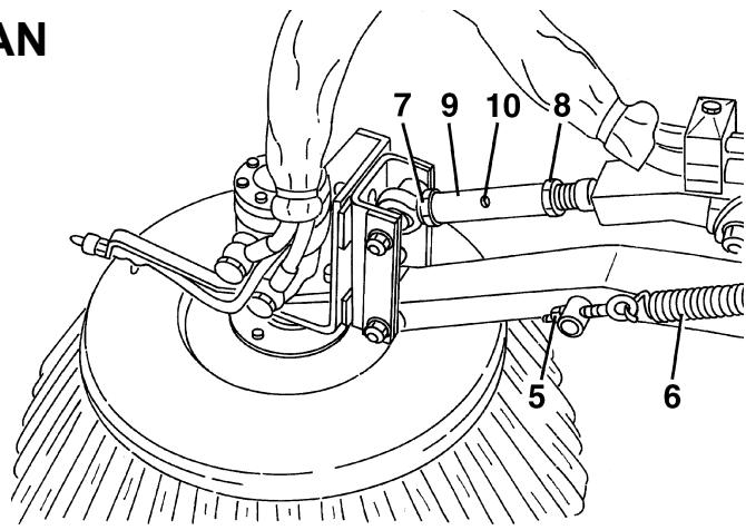
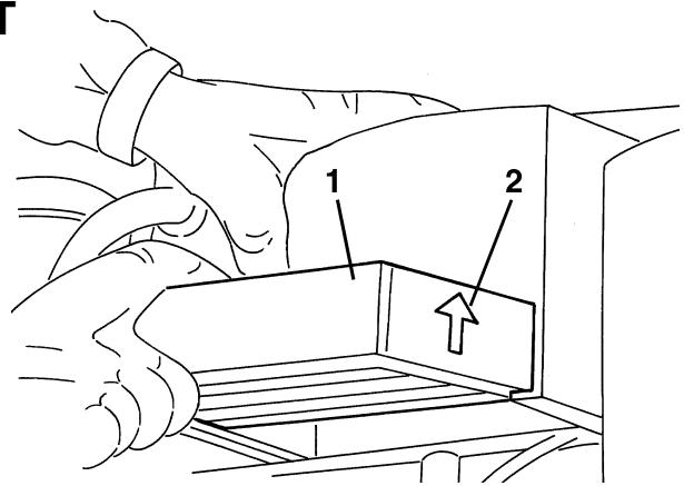
Open the right upper door (28, Fig. G) and remove the gasket (7, Fig. F).
-
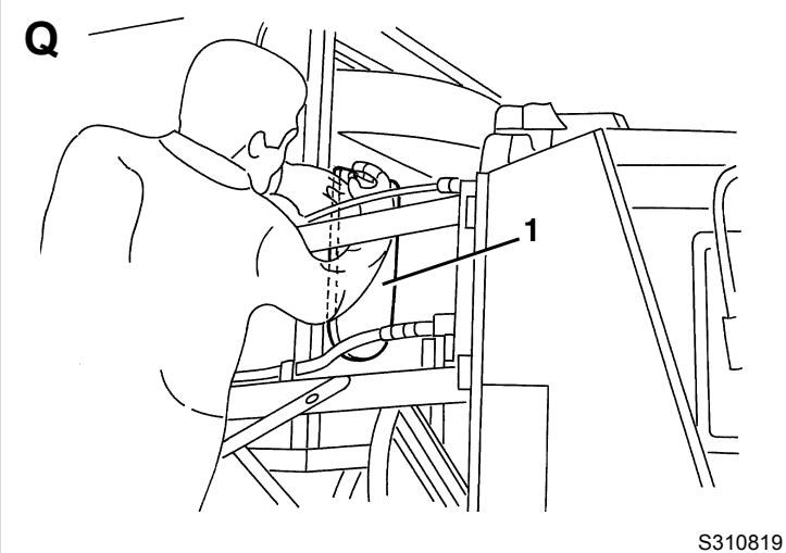
With a suitable ladder, insert and secure the gasket (7, Fig. F) on the hopper suction hole (1, Fig. Q).
-
Lower the hopper completely, as shown in Hopper Dumping paragraph.
-
Release the fastener (42, Fig. G) of the rear suction pipe (43).
-
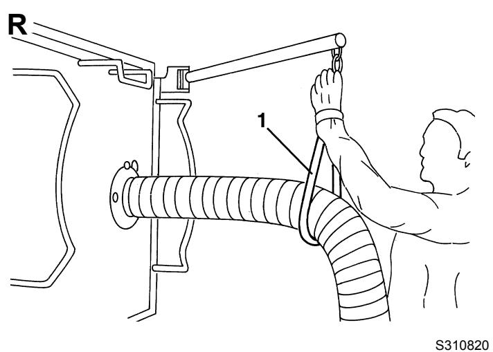
Open the support arm (45, Fig. G) and connect the chain (1, Fig. R) to the suction pipe to support it.
-
Open the dust control system nozzle valve (23, Fig. F).
-
Start the engine as shown in the relevant paragraph.
-
Check that the hopper (7, Fig. G) is lowered and that the warning light (3, Fig. D) is off.
-
Gradually bring forward the engine throttle lever (16, Fig. E) and set the engine speed on the display (17, Fig. D) to:
-
minimum 1,800 rpm
maximum 2,030 rpm -
Turn on the suction fan with the lever (8, Fig. E).
-
Turn on the dust control system water pump with the switch (27, Fig. D) according to the following procedure:
-
When the switch is turned to the first position, the nozzles sprinkle a medium quantity of water (use it when there is little dust)
- When the switch is turned to the second position, the nozzles sprinkle the maximum quantity of water (use it when there is a lot of dust)

CAUTION!
The machine is equipped with an automatic system that, when the operator is on the driver's seat (14, Fig.
E) and the water pump switch (27, Fig. D) is pressed, allows for water supply to the nozzles only if the broom rotation is enabled.
If the operator is not on the driver's seat (14, Fig. E) to use the rear pipe, water can be supplied by the nozzles using the water pump switch (27, Fig. D) only.
- Disengage the parking brake with the lever (13, Fig. E).
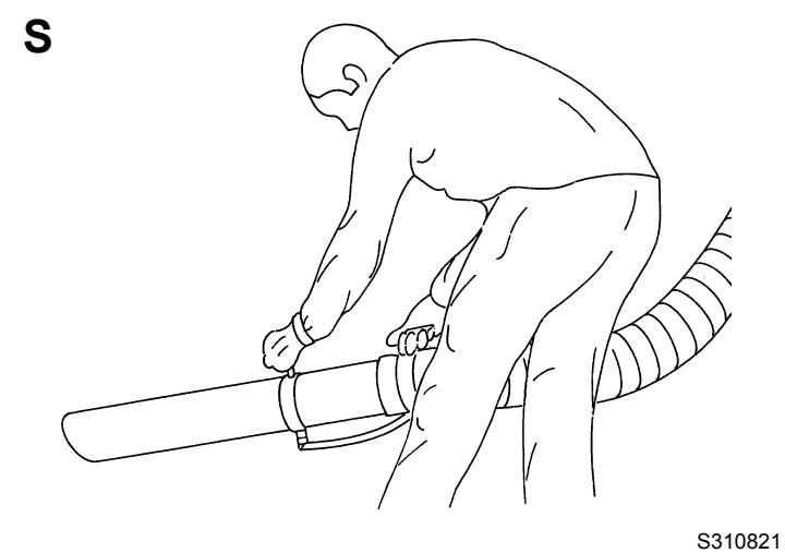
- With the help of an assistant, start to collect debris with the rear suction pipe, by grasping it as shown in Figure S. While working, the machine picks up both light materials such as dust, paper, leaves, etc. and heavy materials such as stones, bottles, etc.
- If necessary, open the valve (23, Fig. F) to supply water to the plastic pipe.
- To restore the machine operation with the suction inlet (17, Fig. G), perform the steps 2 to 17 in the reverse order.
USING THE WINDSCREEN WIPER/WASHER
- Press the switch (23, Fig. D) to sprinkle the detergent on the windscreen.
- Press the switch (33, Fig. D) to start and stop the windscreen wiper.
USING THE CAB HEATING
- To turn on the cab heating, turn the knob (15, Fig. E) counterclockwise as necessary.
- Adjust the blower speed with the knob (6, Fig. E).
- To turn off the cab heating, turn the knob (15, Fig. E) clockwise to the end of stroke.
USING THE CAB CLIMATE CONTROL SYSTEM (*)
(*) Optional
- Turn the climate control knob (5, Fig. E) as necessary.
- Adjust the blower speed with the knob (6, Fig. E).
-
To turn on the lighting and signalling system, use the combination switch (35, Fig. D), having the following functions:
-
Headlights off, with mark (35b) at the symbol O
Running lights on, with mark (35b) at the symbol - Low beam on, with mark (35b) at the symbol l
High beam on, with mark (35b) at the symbol and lowered lever (35a)
High beam temporary on, lifting the lever (35a) - Right turn signal on, bringing the lever (35a) forward
- Left turn signal on, bringing the lever (35a) backward
-
Horn activation, pushing the lever (35a) in the direction shown by the arrow (35c)
-
To turn on the lower headlights (3, Fig. G), or the upper headlights (2), use the selector (30, Fig. D).
Turn on the hazard warning lights with the switch (20, Fig. D).
The suction inlet working light turns on together with the running lights.
To lift/lower the hopper (7, Fig. G) manually (when the diesel engine is faulty, etc.) perform the following procedure.
Hopper manual lifting
- Check that the machine is on a solid and level ground, especially if the hopper (7, Fig. G) is full.
- Turn off the engine, by turning the ignition key (24, Fig. D) counterclockwise, to the end of stroke, then remove it.
- Engage the parking brake (13, Fig. E) and remove the battery release device key (50, Fig. G) by pressing and turning it.
- Open the left lower door (11, Fig. G) by disengaging the fastener (12) with the supplied key.
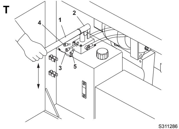
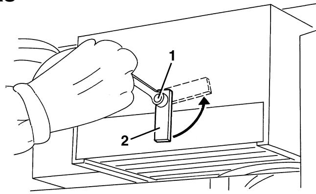
- Remove the manual hand pump lever from its housing (27, Fig. F).
- Install the lever (1, Fig. T) on the hand pump (2).
- Check that the hopper lifting/lowering selector (3, Fig. T) is in lifting position (4).
- Carefully activate the pump (2, Fig. T) with the lever (1) and lift the hopper completely.
- Install the lifted hopper support rods (3, Fig. F), according to the instructions shown on the relevant paragraph.
Hopper manual lowering
- Remove the lifted hopper support rods (3, Fig. F), according to the instructions shown on the relevant paragraph.
- Bring the selector (3, Fig. T) in lowering position (5) and activate the pump (2) with the lever (1) until the hopper is completely lowered.
- Remove the lever (1, Fig. T) from the pump and place it in its housing (27, Fig. F).
- Turn the pump selector to the centre.
- Close the left lower door (11, Fig. G) by engaging the fastener (12) with the supplied key.
LIFTED HOPPER SUPPORT ROD INSTALLATION
Before working under the lifted hopper (1, Fig. F), it is necessary to install the support rods (3) according to the following procedure.

WARNING!
For safety purposes, before working under the lifted hopper, it is necessary to install the support rods (3, Fig. F). This procedure is necessary even if the hopper lifting cylinders are equipped with parachute valves that prevent the hopper from lowering accidentally in case of break/leakage from a pipe/fitting on the hydraulic system.
Support rod installation
- Lift the hopper (7, Fig. G) completely according to the procedure shown in the relevant paragraph.
- Disengage the two rods (2, Fig. F) from the fasteners (4) and bring them in the position (3), by inserting their ends in the housings (20).
- Lower the hopper slightly to lean it on the rods.
Support rod removal
- Lift the hopper slightly to remove it from the rods.
- Disengage the two rods (3, Fig. F) from the housings (20) and bring them in the position (2), then engage and secure them with the fasteners (4).
- Lower the hopper (7, Fig. G) completely according to the procedure shown in the relevant paragraph.
LIFTED HOPPER DOOR SUPPORT ROD INSTALLATION
Before working under the lifted hopper door (44, Fig. G), it is necessary to install the support rod (17, Fig. F) according to the following procedure.
Support rod installation
- Remove the rod (17, Fig. F) from the housing and lift the door as necessary, then install the rod in the housing (18).
Support rod removal
- Perform the procedures described in step 1 in the reverse order.
USING THE HIGH-PRESSURE WATER GUN (*)
(*) Optional
The machine is equipped with a high-pressure water system (optional) to be used for washing the machine or other purposes. The following procedure refers to the high-pressure water gun use.

WARNING!
Do not run the high pressure pump when the water tanks are empty or low (the pump can be damaged).
- Pick up the high-pressure water gun (9, Fig. E) inside the cab.
- Withdraw part of the hose (21, Fig. F) and connect the gun (9, Fig. E) to the quick coupling (22, Fig. F).
- Start the diesel engine at idle speed, as shown in the relevant paragraph.
- Turn on the high-pressure pump by bringing the lever (8, Fig. E) in lower position.
- If necessary, bleed the air from the system by turning the water gun knob completely counter-clockwise and by pressing the water gun lever until the water comes out constantly and at low pressure. Release the water gun lever and turn the knob clockwise to use the high pressure nozzle.
- Run the engine at the desired speed.
- Use the water gun by pressing the relevant trigger.

WARNING!
Protect body parts (eyes, hair, hands, etc.) properly, when performing cleaning procedures using compressed air or water gun.

WARNING!
Do not run the high pressure pump for long periods without using the water gun.
- After using the water gun, perform steps 1 to 4 in the reverse order.
USING THE CAMERA KIT (optional)
- To turn on the video system (1, Fig. AX) and the cameras (4 and 5), press the switch (2) when the ignition key (24, Fig. D) is inserted. The monitor (1) will show the image of the front camera (4).
- When the reverse gear is selected, the video system and the cameras turn on automatically, and the monitor will show the image of the rear camera (5). For the functions of other switches on the right side of the display, refer to the camera kit Manual.
AFTER USING THE MACHINE
After working, before leaving the machine, perform the following operations.
- Turn off the dust control system water pump with the switch (27, Fig. D).
- If open, close the dust control system valves (10, 11, 12, Fig. E).
- Stop the 3rd broom and side broom rotation with the switch (29, Fig. D).
- Lift the 3rd broom by pushing the joystick (15, Fig. D) rearward.
- If necessary, shift the 3rd broom arm to working mode, by moving the joystick (15, Fig. D) to left.
- Lift the suction inlet and side brooms by pressing the push-button (38, Fig. D).
- Turn off the suction fan with the lever (8, Fig. E).
- Turn the engine throttle lever (16, Fig. E) to idle, and hold it in this position for a few minutes to let the system stabilize.
- Check that the hopper (7, Fig. G) is lowered and that the warning light (3, Fig. D) is off.
- If necessary, bring the 3rd broom safety arm from the position (2, Fig. M) (disengaged) to the position (1) (engaged), by engaging the tooth (3) on the bracket (4).
- Clean the hopper, the filters and the suction pipe, check the gaskets and lubricate the suction fan bearings, as shown in Maintenance chapter.
- Turn off the engine, by turning the ignition key (24, Fig. D) counterclockwise, to the end of stroke, then remove it.
- Engage the parking brake with the lever (13, Fig. E).
- The headlights must be turned off.
DUST CONTROL SYSTEM WATER TANK EMPTYING
When necessary, empty the dust control system water tanks according to the following procedure.
- Engage the parking brake (13, Fig. E).
- Turn the ignition key (24, Fig. D) to OFF position and remove it.
- Operating over the right side of the rear axle, unscrew the water filter cover (1, Fig. AE) and remove it together with the filter.
- Drain all the water from the tanks.
- Install the cover (1, Fig. AE) and the filter.
TOWING THE MACHINE
To tow the machine, proceed as follows.
- Engage the parking brake (13, Fig. E).
- Turn the ignition key (24, Fig. D) to OFF position and remove it.
- Disengage the fastener (32, Fig. G) with the supplied key, then lift right under-cab door (31).
- Loosen the drive system pump screw (1, Fig. AU) two turns.
- Tow the machine.
- After towing the machine, tighten the screw (1, Fig. AU), then lower the right under-cab door (31, Fig. G) and engage the fastener with the supplied key.
To transport the machine with a trailer, use the hooks and anchors shown below.

WARNING!
Machine anchor/lifting must be performed by qualified personnel.
Available hooks
- The machine is equipped with the following hooks:
No. 2 lifting hooks (1, Fig. B), to be used only when the hopper is empty.
No. 1 front towing/anchor hook (2, Fig. B).
No. 1 rear towing/anchor hook (3, Fig. B).
Anchorage
-
To anchor the machine in case of transport by trailer, proceed as follows:
-
Set the machine to transport mode (see the procedure in the relevant paragraph).
- Remove the ignition key (24, Fig. D).
- Engage the parking brake (13, Fig. E).
- Close all doors, panels, etc.
- Anchor the machine with the front and rear towing hooks (2 and 3, Fig. B).
- Anchor the machine with two suitable bands (4 and 5, Fig. B), placed over the rear axle support (6), and on the front left and right cab footboards (7) respectively.
Temporary lifting
-
To lift the machine temporarily, proceed as shown below:
-
Set the machine to transport mode (see the procedure in the relevant paragraph).
- Check that the hopper is empty.

WARNING!
If it is necessary to lift the machine in case of emergency and the hopper is not empty, pay special attention, because the waste weight can cause the machine unbalance, moreover the hooks are subject to a greater stress.
- Remove the ignition key (24, Fig. D).
- Engage the parking brake (13, Fig. E).
- Close all doors, panels, etc.
- Anchor the machine to the lifting hooks (1, Fig. B) with suitable ropes.
- Lift the machine carefully, as shortly as possible, with a suitable hoisting system and according to the accident-prevention rules.
MACHINE STORAGE
If the machine is not going to be used for more than 30 days, proceed as follows:
- Empty the dust control system water tanks according to the following procedure.
- Prepare the machine, as shown in the After Machine Use paragraph.
- Store the machine indoor, in a clean and dry place, protected from bad weather conditions and with the following values:
Temperature: +33.8 °F to +122 °F (+1 °C to +50 °C)
Humidity: max. 95%
- Disconnect the negative connector from the battery (34, Fig. F).
- Handle the diesel engine as shown in the relevant Manual.
FIRST PERIOD OF USE
After the first period of use (first 8 hours) it is necessary to perform the following procedures:
- Check the fastening and connecting elements for proper tightening. Check the visible parts for integrity and leaks.
- After the first 50 working hours, perform checks and replacements shown in the Scheduled Maintenance Table.
MAINTENANCE
The lifespan of the machine and its maximum operating safety are ensured by correct and regular maintenance.
The following table provides the scheduled maintenance. The intervals shown may vary according to particular working conditions, which are to be defined by the person in charge of the maintenance.

WARNING!
Maintenance procedures must be performed when the machine is off (ignition key removed).
Moreover, read carefully the instructions in Safety chapter before performing any maintenance procedure.

NOTE
The display (17, Fig. D) is programmed to show an expired or nearly expired maintenance by means of the symbol . Maintenance must be performed at 150 and 500 hours (see Display Functions paragraph).
All scheduled or extraordinary maintenance procedures must be performed by qualified personnel, or by an authorised Service Center.
This Manual contains the Scheduled Maintenance Table and describes only the easiest and most common maintenance procedures.
For other maintenance procedures contained in the Scheduled Maintenance Table or for extraordinary maintenance procedures see the Service Manual that can be consulted at any Service Center.
For scheduled and extraordinary maintenance of the following optional equipment, refer to the relevant Manuals:
Camera kit
SCHEDULED MAINTENANCE TABLE
| Maintenance | After 50 hours | Every 10 hours or before use | Every 150 hours | Every 300 hours | Every 500 hours | Every 1,000 hours | Every 2,000 hours | Long periods |
| Engine oil level check | ||||||||
| Hydraulic system oil level check | ||||||||
| Engine air filter cleaning | ||||||||
| Air filter cyclone block cleaning | ||||||||
| Engine radiator fin cleaning/check | ||||||||
| Engine coolant level check | ||||||||
| Hydraulic system oil cooler fin check | ||||||||
| Battery fluid level check | ||||||||
| Hopper, filter and suction hose cleaning, gasket check and fan bearing lubrication | ||||||||
| Water nozzle and filter cleaning | ||||||||
| Brake fluid level check | ||||||||
| Reverse gear buzzer operation check and sensor adjustment | ||||||||
| Diesel engine start-up safety system check | (8) | |||||||
| Engine fuel filter cleaning | (1) | |||||||
| Engine radiator fin cleaning | (1) (8) | |||||||
| Tyre pressure check | ||||||||
| Suction inlet and skirt height and operation check | ||||||||
| Side broom position check and adjustment | ||||||||
| 3rd broom position check and adjustment | ||||||||
| Hopper and suction hose gasket wear check | (8) | |||||||
| Coolant line check | ||||||||
| Fuel feeding pump filter cleaning | ||||||||
| Dust control system water filter cleaning | ||||||||
| Alternator belt tension check | (8) | (8) | ||||||
| Climate control system compressor belt tension check | (8) | (8) | ||||||
| Parking brake check | ||||||||
| Engine oil change | (2) (3) | |||||||
| Diesel engine oil filter replacement | (3) | |||||||
| Fuel filter element replacement | (3) | |||||||
| Fuel pre-filter replacement | (3) | |||||||
| Engine cylinder head tightening | (7) | |||||||
| Lubrication | (8) | |||||||
| Engine coolant line check | (8) | |||||||
| Hydraulic system oil suction filter replacement | (8) | (8) | ||||||
| Hydraulic system oil drain filter replacement | (8) | (8) | ||||||
| Engine fuel fitting and screw tightening | ||||||||
| Glow plug check | (7) | |||||||
| Injector check | (7) | |||||||
| Engine air filter replacement | ||||||||
| Climate control system air filter replacement | ||||||||
| Alternator belt replacement | (8) | |||||||
| Climate control system belt replacement | (8) | |||||||
| Fuel tank cleaning | (8) | |||||||
| Engine coolant change | (4) (8) | |||||||
| Hydraulic system oil change | (3) (8) | |||||||
| Starter carbon brush check | (7) | |||||||
| Brake system check | (8) | |||||||
| Turbocharger check | (7) | |||||||
| Minor engine overhaul | (5) (7) | |||||||
| Major engine overhaul | (6) (7) |
(1) Every 100 hours, for D703 IE3 engines
(2) For severe conditions, every 150 hours
(3) Or every year
(4) Or every two years
(5) After 4,000 hours
(6) After 8,000 hours
(7) Contact an authorised VM Motori S.p.A. workshop
(8) For the procedure see the Service Manual, at any Nilfisk Service Center.
HOPPER, FILTER AND SUCTION PIPE CLEANING, GASKET CHECK AND SUCTION FAN BEARING LUBRICATION

WARNING!
Protect body parts (eyes, hair, hands, etc.) properly, when performing cleaning procedures using compressed air or water gun.
Preliminary operations
- Empty the hopper (7, Fig. G), drive the machine to a cleaning/washing appointed area, then engage the parking brake (13, Fig. E).
- Lift and dump the hopper (7, Fig. G), according to the procedure shown in the relevant paragraphs.
- Install the support rod (17, Fig. F) as shown on the relevant paragraph.
Hopper cleaning (after every use)
- Clean the hopper (1, Fig. F) and the deflector (14) with pressurized water.
- Carefully check the suction sealing gasket (19, Fig. F) for integrity, and replace it if necessary.
Suction pipe cleaning (after every use)
- Thoroughly clean the suction pipe (6, Fig. F) inside, up to the suction inlet, with pressurised water.
- Carefully check the suction pipe gasket (5, Fig. F) for integrity, and replace it if necessary.
Suction filter and fan cleaning (after every use)
- Inside the hopper, remove the fasteners (16, Fig. F) of the suction filter (15).
-
Remove the suction filter (15, Fig. F).
-
Operating in the compartment (13, Fig. F), wash the fan (1, Fig. U) with pressurised water; check that all fan sectors (2) are clean.
-
Clean the suction filter (1, Fig. V) with pressurised water.
- Install the suction filter and secure it with the fasteners (16, Fig. F).
- Remove the door support rod (17, Fig. F) and lower the hopper (7, Fig. G) according to the instructions shown in the relevant paragraph.
- Turn the ignition key (24, Fig. D) to OFF position and remove it.
Breather filter cleaning (after every use)
- With a ladder and the help of an assistant, disengage the fasteners (26, Fig. G) of the breather filter hood (27).
- Open the hood (1, Fig. W) and install the safety pins (2).
- Remove the mounting screws (1, Fig. X), then remove the breather filter (2).
- Clean the breather filter (1, Fig. Y) with pressurised water.
- Install the breather filter and its hood performing steps from 15 to 17 in reverse order.
Suction fan bearing lubrication (after every use)
- Open the left side door (9, Fig. G).
- Lubricate the suction fan bearings with the grease nipples (1, Fig. Z).
Grease quantity to be applied:
4-5 pumping, in case of a manual pump.
15 - 20 seconds of injection, in case of an air pump.
Protect body parts (eyes, hair, hands, etc.) properly, when performing cleaning procedures using compressed air or water gun.
Preliminary operations
- Engage the parking brake (13, Fig. E).
- Turn the ignition key (24, Fig. D) to OFF position and remove it.
Cleaning of nozzles and filters on side brooms
- Unscrew the ring nuts (1, Fig. AA).
- Remove and clean the nozzles (2, Fig. AA) and filters (3) with compressed air. Remove calcium deposits. If necessary, replace the filters (3).
- Install the filters and nozzles, and secure them with the ring nuts.
Cleaning of nozzles and filters in the suction pipe, from suction inlet to hopper
- Empty the hopper (7, Fig. G); if it contains a small quantity of waste, it is not necessary to dump it.
- Drive the machine on a solid and level ground, then engage the parking brake (13, Fig. E).
- Lift the hopper (7, Fig. G), according to the procedure shown in the relevant paragraph.
- Turn the ignition key (24, Fig. D) to OFF position and remove it.
- To avoid that the hopper lowers by accident, install the lifted hopper support rods (3, Fig. F), according to the instructions shown on the relevant paragraph.
- Operating inside the suction pipe (6, Fig. F), with a 0.55 in (14 mm) socket wrench (1, Fig. AB), unscrew the nozzle (2, Fig. AB, AC) and remove the filter (3) (check the actual position of the nozzle).
- Clean the nozzle (2, Fig. AB, AC) and filter (3) with compressed air. Remove calcium deposits. If necessary, replace the filter (3).
- Install the filter and nozzle in the reverse order of removal.
- Remove the lifted hopper support rods (3, Fig. F) and lower the hopper (7, Fig. G) (see the procedure in the relevant paragraphs).
Cleaning of nozzle and filter in the rear suction pipe (optional)
- Loosen the clamp (1, Fig. AD) and separate the rigid part of the rear suction pipe (2) from the hose (3).
- Operating inside the pipe (2, Fig. AD), with a 0.55 in (14 mm) socket wrench, unscrew the nozzle (4) and remove the filter (5) (check the actual position of the nozzle).
- Clean the nozzle (4, Fig. AD) and filter (5) with compressed air. Remove calcium deposits. If necessary, replace the filter (5).
- Install the filter and nozzle in the reverse order of removal.
- Install the hose (3, Fig. D) on the rigid part of the rear suction pipe (2) and secure with the clamp (1).
DUST CONTROL SYSTEM WATER FILTER CLEANING

WARNING!
Protect body parts (eyes, hair, hands, etc.) properly, when performing cleaning procedures using compressed air or water gun.

NOTE
When the filter is removed, the water inside the tanks comes out. It is advisable to perform this maintenance procedure when the tanks are empty.
- Engage the parking brake (13, Fig. E).
- Turn the ignition key (24, Fig. D) to OFF position and remove it.
- Operating over the right side of the rear axle, unscrew the water filter cover (1, Fig. Z) and remove it together with the filter.
- Separate the filter (2, Fig. Z) from the cover (3), then wash and clean them. If necessary, replace the filter.
- Install the filter and the cover.
HYDRAULIC SYSTEM OIL LEVEL CHECK

CAUTION!
This procedure must be performed with the hopper (6, Fig. G) completely lowered.
- Engage the parking brake (13, Fig. E).
- Start the engine as shown in the relevant paragraph.
- Open the left side upper and lower doors (9 and 11, Fig. G) by disengaging the fasteners (10 and 12) with the supplied key.
- Check that there are no oil leaks in the upper area of the hydraulic system oil tank.
- Turn off the engine, by turning the ignition key (24, Fig. D) counterclockwise, to the end of stroke, then remove it.
- Using the indicator (35, Fig. F), check that the oil level in the tank is between the MIN and MAX marks.
- If necessary, unscrew the plug (31, Fig. F) and top up. For the types of oil to be used, see the Technical Data chapter.

NOTE
Top up by using the same type of oil that is in the tank.
- Screw the plug (31).
- Close the left side upper and lower doors (11 and 9, Fig. G) by engaging the fasteners (10 and 12) with the supplied key.
HYDRAULIC SYSTEM OIL COOLER FIN CLEANING CHECK

WARNING!
Protect body parts (eyes, hair, hands, etc.) properly, when performing cleaning procedures using compressed air or water gun.
- Empty the hopper (7, Fig. G); if it contains a small quantity of waste, it is not necessary to dump it.
- Drive the machine on a solid and level ground, then engage the parking brake (13, Fig. E).
- Lift the hopper (7, Fig. G), according to the procedure shown in the relevant paragraph.
- Turn the ignition key (24, Fig. D) to OFF position and remove it.
- To avoid that the hopper lowers by accident, install the lifted hopper support rods (3, Fig. F), according to the instructions shown on the relevant paragraph.
- Close the left and right side upper doors (9 and 28, Fig. G) by engaging the fasteners (10) and (29) with the supplied key.
- Remove the screws, then remove the engine compartment panel (11, Fig. F).
- Open the right side lower door (34, Fig. G) by disengaging the fastener (35) with the supplied key.
- Clean the hydraulic system oil cooler fins (9, Fig. F) with compressed air (maximum 87.0 psi [6 Bar]). If necessary, point the compressed air in the opposite direction of the cooling air.
- Inside the radiator (9, Fig. F), check that the fan turns freely.
- Perform steps 3 to 8 in the reverse order.
HYDRAULIC SYSTEM FILTER CHECK/REPLACEMENT
- Turn off the engine, by turning the ignition key (24, Fig. D) counterclockwise, to the end of stroke, then remove it.
- Engage the parking brake (13, Fig. E).
- Remove the driver's seat panel (2, Fig. AF) by unscrewing the 5 mounting screws (3).
- Check that the clogging indicator (4, Fig. AF) is in the green area (5) at the centre mark.
- If the clogging indicator (4, Fig. AF) is in the red area (6) at the centre line the filter element (1) is to be replaced.
- Remove the element (1) with a suitable tool and pay attention to oil leakages.
- Replace the filter element with an original spare part.

WARNING!
The oil and filters should be disposed of properly according to the environmental laws in force.
- Install the driver's seat panel (2).
BATTERY FLUID LEVEL CHECK

WARNING!
Protect body parts (eyes, hair, hands, etc.) properly, when performing battery check and cleaning procedures.
- Engage the parking brake (13, Fig. E).
- Turn off the engine, by turning the ignition key (24, Fig. D) counterclockwise, to the end of stroke, then remove it.
- To disconnect the battery (34, Fig. F), turn the key of the release device (50, Fig. G) and then remove it by pressing and turning it.
- Open the left side upper and lower doors (9 and 11, Fig. G) by disengaging the fasteners (10 and 12) with the supplied key.
-
Check the colour of the hygrometer (43, Fig. F); if it is green the battery is ok, if is red:
-
The battery must be refilled with distilled water
The battery must be charged.
If the colour of the hygrometer (43, Fig. F) is still red, the battery must be replaced.
- If necessary, clean the battery.
- Check the battery terminals for oxidation.
- Close the left side upper and lower doors (11 and 9, Fig. G) by engaging the fasteners (10 and 12) with the supplied key.
- Engage the parking brake (13, Fig. E).
- Turn the ignition key (24, Fig. D) to OFF position and remove it.
- Check the brake system fluid level in the tank (7, Fig. E). The level must be at 0.4 in (1 cm) from the tank filler neck. If necessary, top up using the same type of brake fluid that is in the line.
Type of fluid used: DOT4.
REVERSE GEAR BUZZER SENSOR CHECK
Check that, when the machine moves in reverse, the relevant buzzer sounds.
If necessary, perform the adjustment according to the instructions in the Service Manual.
TYRE PRESSURE CHECK
- Engage the parking brake (13, Fig. E).
- Turn the ignition key (24, Fig. D) to OFF position and remove it.
-
The tyre pressure should be as follows:
-
Front tyres: 72.5 psi (5.0 Bar)
Rear tyres: 72.5 psi (5.0 Bar)

WARNING!
Please respect the recommended tyre pressure as stated in the relevant decals.
The manufacturer rating is based on standard drive speed and standard load rating, different from the actual machine application.
SUCTION INLET AND SKIRT HEIGHT AND OPERATION CHECK
Preliminary operations
- Engage the parking brake (13, Fig. E).
- Lift the suction inlet (17, Fig. G) according to the procedure shown in the relevant paragraph.
- Turn the ignition key (24, Fig. D) to OFF position and remove it.
Suction inlet wheel check
- Check that the three wheels (1, Fig. AH) of the suction inlet are in good conditions and turn freely (they must not be bent/ misshapen because of bumps or excessive pressure, etc.). Check also that the rubber thickness (2) is not lower than some millimetre.
If necessary replace the wheels (1) (see the procedure in the Service Manual).
Sliding panel check
- Check that the main sliding panel (3, Fig. AH) and the front sliding panels (4) and (5) are in good conditions and that their thickness (6) is not lower than 0.2 in (5 mm), otherwise replace them (see the procedure in the Service Manual).
It is important to replace the sliding panels (3), (4), (5) when they are not completely worn, to avoid damaging the relevant mounting screws and making them difficult to remove.
Replace the sliding panels (3), (4), (5) as a unit, to avoid steps in the union areas (7), caused by different levels of wear.
Suction inlet skirt, baffle plate and wheel adjustment check
- Check that the skirt (8, Fig. AH) and baffle plate (9) are integral and that they do not have excessive tears (10) or lacerations (11), which can affect the suction inlet operation.
If necessary replace the skirt (8) and the baffle plate (9) (see the procedure in the Service Manual). - Drive the machine on a level ground and lower the suction inlet (17, Fig. G) according to the procedure shown in the relevant paragraph.
- Turn the ignition key (24, Fig. D) to OFF position and remove it.
- Check that the distance (12, Fig. AH) of the skirt from the ground is not bigger than 0.4 in (1 cm). Greater distances can affect the suction inlet operation.
If necessary replace the skirt (8) (see the procedure in the Service Manual).
- Check that all the wheels (1, Fig. AH) contact the ground.
If the rear wheel does not contact the ground, or if it contacts the ground with too much force, adjust its height according to the following procedure:
-
On both sides of the suction inlet, unscrew/screw the self-locking nuts (1, Fig. AI) until the rear wheel reaches the correct position.
-
Also check that, when the three wheels (1, Fig. AH) contact the ground, the sliding panels (3), (4), (5) do not touch the ground, otherwise the wheels (1) must be replaced to avoid an excessive wear of the sliding panels (for wheel replacement procedure, see the Service Manual).
- The adjuster (2, Fig. AH) is used to balance the suction inlet when it is lifted.
-
Start the machine according to the procedure shown in the relevant paragraph, then lift the skirt (8, Fig. AH) and check that it lifts freely. Check that it lifts also when a force of some kg is applied (simulating to move bottles or other heavy objects that must then be collected). If necessary, adjust the opening force of the skirt (8) according to the following procedure:
-
Turn off the machine.
-
Loosen the control valve locknut (13, Fig. AH) and turn the screw (14) as necessary, reminding that:
-
The opening force decreases by loosening the screw;
- The opening force increases by tightening the screw.
-
When the adjustment is completed, tighten the locknut (13, Fig. AH).
-
Assemble the components in the reverse order of disassembly.
SIDE BROOM HEIGHT CHECK AND ADJUSTMENT

NOTE
Brooms of various hardness are available. This procedure is applicable to all types of brooms.
Check
-
Check the side brooms for proper height and tilting, according to the following procedure:
-
Drive the machine on a level ground.
While keeping the machine stationary, fully lower the side brooms and allow them to rotate for a few seconds. - Stop and lift the side brooms, then move the machine.
-
Check that the size and orientation of the prints left by the side brooms are as follows:
-
The right side broom must touch the ground along a circle arc ranging from "11 o'clock" position to "4 o'clock" position (1, Fig. AJ).
-
The left side broom must touch the ground along a circle arc ranging from "8 o'clock" position to "1 o'clock" position (2, Fig. AJ).
-
Adjust the broom height when the prints are out of specification, according to the following procedure.
-
Engage the parking brake with the lever (13, Fig. E).
- Turn the ignition key (24, Fig. D) to OFF position and remove it.
Side broom height adjustment
-
On both sides of the machine, operate on the tensioning self-locking nut (3, Fig. AK) of the spring (4) and consider the following:
-
To lower the broom, the nut (3) must be unscrewed;
-
To lift the broom, the nut (3) must be screwed.
-
Perform step 1 again.
Side broom forward tilting angle (5, Fig. AK) adjustment
- On both sides of the machine, loosen the locknuts (6 and 7, Fig. AK), then adjust the forward tilting angle (5) by placing a lever in the hole (9) and turning the tie rod (8).
- When the adjustment is completed, tighten the locknuts (6) and (7).
- Perform step 1 again.
Side broom side tilting angle (10, Fig. AK) adjustment
- On both sides of the machine, loosen the screws (11 and 12, Fig. AK), then adjust the side tilting angle (10). When the adjustment is completed, tighten the screws (11) and (12).
- Perform step 1 again.
Side broom side position adjustment
- The purpose of this adjustment is to improve the side position of the brooms as to the suction inlet (17, Fig. G).
- To perform the adjustment, loosen/tighten the self-locking nuts (1 and/or 2, Fig. AL), thus changing the side position of the brooms. To have a optimum adjustment, the arms must be slightly tensioned outwards.
- When the side brooms are too worn out, the adjustment is not possible; replace the brooms according to the instructions in the relevant paragraph.
3RD BROOM POSITION CHECK AND ADJUSTMENT

NOTE
Brooms of various hardness are available. This procedure is applicable to all types of brooms.
3rd broom position check
-
Check the 3rd broom for proper height and tilting, according to the following procedure:
-
Drive the machine on a level ground.
- Start the machine and bring the 3rd broom arm (1, Fig. AM) straight in front of the cab (as shown in the figure) according to the procedure shown in the relevant paragraph.
- Keeping the machine stationary, lower the 3rd broom completely (2, Fig. AM) and allow it to rotate for a few seconds.
- Stop and lift the 3rd broom, then move the machine.
-
Check that the size and orientation of the print left by the 3rd broom is as follows:
-
The broom must touch the ground along a circle arc ranging from "10 o'clock" position to "2 o'clock" position (3, Fig. AM).
- The broom forward tilting angle (4, Fig. AM) must be 10 degrees approximately.
If necessary, adjust the broom according to the following procedure.
- Engage the parking brake (13, Fig. E).
- Turn the ignition key (24, Fig. D) to OFF position and remove it.
3rd broom height adjustment
-
Operate on the tensioning self-locking nut (5, Fig. AN) of the spring (6) and consider the following:
-
To lower the broom, the nut (5) must be unscrewed;
-
To lift the broom, the nut (5) must be screwed.
-
Perform step 1 again.
3rd broom forward tilting angle (4, Fig. AM) adjustment
- Loosen the locknuts (7 and 8, Fig. AN), then adjust the forward tilting angle (4) by placing a lever in the hole (10) and turning the tie rod (9).
- When the adjustment is completed, tighten the locknuts (7) and (8).
- Perform step 1 again.
- When the broom is too worn out the adjustment is no more possible; replace the broom according to the instructions in the relevant paragraph.
BROOM REPLACEMENT

NOTE
Brooms of various hardness are available. This procedure is applicable to all types of brooms.

CAUTION!
It is advisable to wear protective gloves when replacing the side brooms because there can be sharp debris between the bristles.
- Lift the brooms and engage the parking brake (13, Fig. E).
- Turn the ignition key (24, Fig. D) to OFF position and remove it.
- Remove the lower centre screw (1, Fig. AO), then remove the broom (2) to be replaced. Recover the key.
- Remove the screws (3, Fig. AO) and the flange (4) from the removed broom.
- Install the flange (4, Fig. AO) and secure it with the screws (3) on the new broom.
- Install the new broom (2, Fig. AO) with the key, then tighten the centre screw (1).
- Adjust the height of the new broom according to the procedure shown in the relevant paragraph.
PARKING BRAKE CHECK
- Engage the parking brake lever (13, Fig. E) and check for proper operation. Check also that the brake operates in the same way on both the front wheels.
- If necessary, adjust the parking brake according to the instructions in the Service Manual.
ENGINE OIL LEVEL CHECK
- Engage the parking brake (13, Fig. E).
- Turn the ignition key (24, Fig. D) to OFF position and remove it.
- Open the left side lower door (11, Fig. G) by disengaging the fastener (12) with the supplied key.
- Check the oil level as shown in the Diesel Engine Manual.
- Close the left side lower door (11, Fig. G) by engaging the fastener (12) with the supplied key.
ENGINE OIL CHANGE
- Empty the hopper (7, Fig. G); if it contains a small quantity of waste, it is not necessary to dump it.
- Drive the machine on a solid and level ground, then engage the parking brake (13, Fig. E).
- Lift the hopper (7, Fig. G), according to the procedure shown in the relevant paragraph.
- Turn the ignition key (24, Fig. D) to OFF position and remove it.
- To avoid that the hopper lowers by accident, install the lifted hopper support rods (3, Fig. F), according to the instructions shown on the relevant paragraph.
- Close the left and right side upper doors (9 and 28, Fig. G) by engaging the fasteners (10) and (29) with the supplied key.
- Remove the screws, then remove the engine compartment panel (11, Fig. F).
- Open the left side lower door (11, Fig. G) by disengaging the fastener (12) with the supplied key.
- Change the oil as shown in the diesel engine Manual.
- Perform steps 3 to 8 in the reverse order.
ENGINE OIL FILTER REPLACEMENT

NOTE
This procedure must be performed when the engine oil has been drained.
- Empty the hopper (7, Fig. G); if it contains a small quantity of waste, it is not necessary to dump it.
- Drive the machine on a solid and level ground, then engage the parking brake (13, Fig. E).
- Lift the hopper (7, Fig. G), according to the procedure shown in the relevant paragraph.
- Turn the ignition key (24, Fig. D) to OFF position and remove it.
- To avoid that the hopper lowers by accident, install the lifted hopper support rods (3, Fig. F), according to the instructions shown on the relevant paragraph.
- Close the left and right side upper doors (9 and 28, Fig. G) by engaging the fasteners (10) and (29) with the supplied key.
- Remove the screws, then remove the engine compartment panel (11, Fig. F).
- Open the left side lower door (11, Fig. G) by disengaging the fastener (12) with the supplied key.
- Replace the oil filter as shown in the Diesel Engine Manual.
- Perform steps 3 to 8 in the reverse order.

CAUTION!
When replacing the engine oil filter, it is recommended to change the engine oil as shown in the relevant paragraph.
ENGINE AIR FILTER CLEANING/REPLACEMENT

WARNING!
Protect body parts (eyes, hair, hands, etc.) properly, when performing cleaning procedures using compressed air or water gun.
Preliminary operations
- Lift the hopper and engage the support rods as shown in the relevant paragraph.
- Engage the parking brake (13, Fig. E).
- Turn off the engine, by turning the ignition key (24, Fig. D) counterclockwise, to the end of stroke, then remove it.
- Remove the engine case (11, Fig. F) by unscrewing the two mounting knobs (40).
Filter cleaning/replacement
- Remove the 4 side fasteners (1, Fig. AR) on the left side of the machine and remove the cover (2).
- Remove the plastic frame with the filter element (3, Fig. AR).
- Remove the filter element (4, Fig. AR) from the plastic frame (5) and dispose of it properly according to the environmental laws in force.
- Remove the secondary filter element (6, Fig. AR) by pulling the built-in handles.
- With compressed air (maximum 87.0 psi [6 Bar]), clean the filter elements (4) and (6) carefully, blowing from the inside to the outside (in the opposite direction of the suction flow).
- If necessary, replace the filter elements and dispose of them properly according to the environmental laws in force.
- Install the filter elements (4) and (6) by performing steps 5, 6, 7 and 8 in the reverse order.
- When the cyclone block (7, Fig. AR) is to be cleaned, remove the mounting screw (8) from the threaded insert (9) and then remove the cyclone block (7) from its housing (10).
- Clean the cyclone block (7) with compressed air or water.
- Install the cyclone block (7).
ENGINE RADIATOR FIN CLEANING CHECK
- Empty the hopper (7, Fig. G); if it contains a small quantity of waste, it is not necessary to dump it.
- Drive the machine on a solid and level ground, then engage the parking brake (13, Fig. E).
- Lift the hopper (7, Fig. G), according to the procedure shown in the relevant paragraph.
- Turn the ignition key (24, Fig. D) to OFF position and remove it.
- To avoid that the hopper lowers by accident, install the lifted hopper support rods (3, Fig. F), according to the instructions shown on the relevant paragraph.
- Close the left and right side upper doors (9 and 28, Fig. G) by engaging the fasteners (10) and (29) with the supplied key.
- Remove the screws, then remove the engine compartment panel (11, Fig. F).
- Open the left side lower door (11, Fig. G) by disengaging the fastener (12) with the supplied key.
- Check the radiator fin cleaning as shown in the diesel engine Manual.
- Perform steps 3 to 8 in the reverse order.
ENGINE COOLANT LEVEL CHECK
- Engage the parking brake (13, Fig. E).
- Turn the ignition key (24, Fig. D) to OFF position and remove it.
- With a suitable ladder, reach the coolant tank (5, Fig. G).

WARNING!
The coolant line is pressurized; do not perform any check until the engine has cooled down and, even if the engine is cold, the tank plug (2, Fig. AQ) must be opened with extreme care.
- Check that the coolant level in the tank (1, Fig. AQ) is between the minimum and maximum marks, as shown in the diesel engine Manual. If necessary, unscrew the plug (2) and top up.
-
Coolant components:
-
50% of AGIP antifreeze
50% of water -
After top up, tighten the plug (2, Fig. AQ).
ENGINE FUEL FILTER REPLACEMENT
- Engage the parking brake (13, Fig. E).
- Turn the ignition key (24, Fig. D) to OFF position and remove it.
- Open the right under-cab door (31, Fig. G) by disengaging the fastener (32) with the supplied key.
- Open the right side lower door (34, Fig. G) by disengaging the fastener (35) with the supplied key.
- Replace the fuel filter (1, Fig. AP) as shown in the diesel engine Manual.
- Perform steps 3 to 5 in the reverse order.
FUEL PRE-FILTER REPLACEMENT
- Engage the parking brake (13, Fig. E).
- Turn off the engine, by turning the ignition key (24, Fig. D) counterclockwise, to the end of stroke, then remove it.
- Open the right side upper door (28, Fig. G) by disengaging the fasteners (29) with the supplied key.
- Open the right side lower door (34, Fig. G) by disengaging the fastener (35) with the supplied key.
- Replace the fuel pre-filter (44, Fig. F) by loosening the clamps (2, Fig. AV) and by removing the hose (1) from the fittings on the element (3). Pay attention to the fuel that spills out during this procedure.
- Replace the filter element (3, Fig. AV).
- Perform steps 3 to 5 in the reverse order.
CAB AIR FILTER REPLACEMENT
- Empty the hopper (7, Fig. G); if it contains a small quantity of waste, it is not necessary to dump it.
- Drive the machine on a solid and level ground, then engage the parking brake (13, Fig. E).
- Lift the hopper (7, Fig. G), according to the procedure shown in the relevant paragraph.
- Turn the ignition key (24, Fig. D) to OFF position and remove it.
- To avoid that the hopper lowers by accident, install the lifted hopper support rods (3, Fig. F), according to the instructions shown on the relevant paragraph.
- Open the left side upper door (9, Fig. G) by disengaging the fastener (10) with the supplied key.
- With a suitable ladder, loosen the screw (1, Fig. AS) and turn the retainer (2).
- Remove the cab air filter (1, Fig. AT).
- Install the new filter (1, Fig. AT) with the arrows (2) pointing in the direction of the air flow (upwards).
- Perform steps 3 to 7 in the reverse order.
WHEEL REPLACEMENT
Preliminary operations
- Turn the ignition key (24, Fig. D) to OFF position and remove it.
- Engage the parking brake (13, Fig. E).
- Check that the machine cannot move with one wheel lifted (the parking brake operates only on the front wheels). If necessary, keep the machine stationary by placing wedges on the wheels contacting the ground.
- Remove the wheel according to the following procedure.
Front wheel removal/installation
- Open the right side upper door (28, Fig. G) by disengaging the fastener (29) with the supplied key.
- Unscrew the knobs (38, Fig. F) and remove the machine lifting bracket (37).
- Near the wheel to be removed (1, Fig. AG), place the lifting bracket (2) on the bosses (3) of the machine frame as shown in the figure, then secure it with the split pin (4). Place a jack (5) under the bracket (2), as shown in the figure.
- Loosen tyre nuts before jacking.

WARNING!
The jack (5, Fig. AG) is not part of the machine equipment. Use a suitable jack with a minimum lifting capacity of 6,614 lb (3,000kg)
- Activate the jack (5, Fig. AG) carefully, and lift the wheel (1) until it is slightly detached from the ground.
- Unscrew the mounting nuts and remove the wheel (1, Fig. AG).
- Install the wheel (1, Fig. AG) by performing steps from 5 to 9 in the reverse order. Wheel mounting nut tightening torque: 295 lb·ft (400 N·m).
Rear wheel removal/installation
- Place a jack (6, Fig AG) under the relevant housing (9) in the rear axle (7), as shown in the figure.
- Loosen tyre nuts before jacking.

WARNING!
The jack (5, Fig. AG) is not part of the machine equipment. Use a suitable jack with a minimum lifting capacity of 6,614 lb (3,000 kg).
- Activate the jack (6, Fig. AG) carefully, and lift the wheel (8) until it is slightly detached from the ground.
- Unscrew the mounting nuts and remove the wheel (8, Fig. AG).
- Install the wheel (8, Fig. AG) by performing steps from 11 to 13 in the reverse order.
Wheel mounting nut tightening torque: 295 lb·ft (400 N·m).
FUSE REPLACEMENT
- Engage the parking brake (13, Fig. E).
- Turn the ignition key (24, Fig. D) to OFF position and remove it.
- Remove the transparent cover of the fuse box (25 or 34, Fig. D) and replace the relevant fuse among the following:
Fuse box (25, Fig. D)
- Free fuse holder (10 A)
- Free fuse holder (7.5 A)
- Parking brake warning buzzer and water-in-fuel sensor fuse (10 A)
- Dashboard fuse (7.5 A)
- Reverse gear warning buzzer, cameras, start safety relay, and hopper door fuse (10 A)
- Skirt solenoid valve fuse (10 A)
- Broom rotation fuse (10 A)
- Relay board fuse (10 A)
- Lifted hopper warning light/windscreen washer fuse (7.5 A)
- Dust control system water pump fuse (15 A)
- Climate control system fuse (15 A)
- Hydraulic system oil cooling fan fuse (20 A)
Fuse box (34, Fig. D)
- High beam fuse (15 A)
- Running light fuse (7.5 A)
- Hazard warning light and horn fuse (10 A)
- Low beam fuse (15 A)
- Running light fuse (7.5 A)
- Glow plug control unit fuse (7.5 A)
- Turn signal fuse (7.5 A)
- Flashing light fuse (7.5 A)
- Fuel solenoid valve fuse (engine off) (10 A)
- Brake light fuse (10 A)
- Windscreen wiper fuse (7.5 A)
-
Climate control system blower fuse (20 A)
-
Install the transparent cover of the fuse box (25 or 34, Fig. D).
SUCTION INLET DISASSEMBLY/ASSEMBLY

NOTE
This is a basic procedure, it is often recalled during other procedures, when necessary.
Disassembly
- Remove the side brooms (see the procedure in the relevant paragraph).
- Move the 3rd broom (21, Fig. G) aside, and lower the suction inlet (17) according to the procedure shown in the relevant paragraph.
- Engage the parking brake (13, Fig. E).
- Turn the ignition key (24, Fig. D) to OFF position and remove it.
- Mark the position of the pipes (1 and 2, Fig. AY) (for proper assembly), then disconnect them from the suction inlet (3) and plug them.
- Mark the position of the pipes (4 and 5, Fig. AY) (for proper assembly), then disconnect them from the suction inlet (3) and plug them.
- Disconnect the dust control system pipes (6 and 7, Fig. AY).
- Disconnect the connectors (8 and 9, Fig. AY) and remove the gasket.
- Remove the screws (10, Fig. AY).
- Move the suction inlet (3, Fig. AY) forward, and loosen the suction pipe clamp (11).
- Disconnect the suction pipe (12, Fig. AY) from the suction inlet.
- On both sides of the suction inlet, unscrew the nuts (13, Fig. AY) and disconnect the relevant springs.
- Remove the suction inlet (3).
- Collect the pipes (15, Fig. AY) disconnected from the suction inlet, and secure them with clamps (14). Fit a dust boot to prevent dirt and foreign material from entering the pipes (15).
Assembly
- Assemble the components in the reverse order of disassembly.
- If necessary, check the suction inlet and skirt height and operation (see the procedure in the relevant paragraph).
3RD BROOM ARM DISASSEMBLY/ASSEMBLY

NOTE
This is a basic procedure, it is often recalled during other procedures, when necessary.

CAUTION!
This procedure is applicable only for sweepers with appropriate fittings for installation of snow brush.
Disassembly
- Extend the 3rd broom arm (23, Fig. G) and lift the broom (21) according to the procedure shown in the relevant paragraph.
- Turn off the engine and engage the parking brake (13, Fig. E).
- Operating according to the safety rules, with a proper hoisting system (1, Fig. AZ), sling the 3rd broom arm (2) in the points shown in the figure. Move the pipes and cable aside, to avoid squashing them during the lifting operation. 3rd broom arm weight: approx. 176.4 lb (80 kg).
- Disconnect the electrical connector (3, Fig. AZ).
- Disconnect the hydraulic system quick couplings (4, Fig. AZ) from the corresponding pipe couplings (5), then install the protection covers.
- Disconnect the dust control system quick coupling (6, Fig. AZ) from the corresponding pipe coupling (7), then install the protection covers.
- Inside the cab, remove the screw (8, Fig. AZ), then remove the panel (9).
- Slightly tighten the hoisting system (1, Fig. AZ), then remove the screws (10) and the nut (11).
- Remove the 3rd broom arm (2, Fig. AZ).
Assembly
- Assemble the components in the reverse order of disassembly.
- If necessary, check and adjust the 3rd broom position (see the procedure in the relevant paragraph).
WINTER MAINTENANCE
In winter, perform the following maintenance procedures carefully.
Procedures for machine storage or for machines working at less than +32^ (0^)
- Drain the nozzles and water tanks.
- Drain and clean/replace the water filter.
- Pour antifreeze in the water tanks (check the quantity).
- Turn on the water pump (see the procedure in the relevant paragraphs) to let the antifreeze flow through the system until it comes out from the broom nozzles, from the suction hose nozzle and from the rear pipe nozzle (if equipped). When the antifreeze comes out from the nozzles, stop the pump.
- Start the engine as shown in the relevant paragraph.
- Turn on the high-pressure washing system pump (see the procedure in the relevant paragraphs) and let the antifreeze flow through the high-pressure washing system until it comes out of the water gun. When the antifreeze comes out, stop the pump.

WARNING!
Do not use the dust control system when the outside temperature is lower than +32^ ( 0^ ) because it can create ice sheets on the pavement.
Procedures to perform when the machine has been stored for two months
- Replace the engine oil and oil filter (see the relevant paragraphs).
- Fill the fuel tank (see the relevant paragraph).
- Lubricate the machine.
- Charge the battery.
- Check the tyre pressure (see the relevant paragraph).
Procedures to perform when the machine has been stored for three months
- Perform the same procedures of the second month.
- Each month connect a battery charger and keep the battery charged for 12/24 hours.
SAFETY FUNCTIONS
The machine is equipped with the following safety functions.
Reverse gear buzzer
The machine is equipped with a sensor and a buzzer to indicate that the machine is moving in reverse.
Broom speed limiter
The machine is calibrated to stop broom rotation when the engine speed is above 2,050 rpm.
Joystick safety push-button
The push Buttons on the joystick are active only if the safety push-button (on the joystick) is pressed.
Safety device for control sequence during broom start-up
The suction inlet lowers only when the broom switch is pressed; the broom rotation starts only when the suction inlet is completely lowered.
Sensor for engine start-up inhibition when the drive pedal is pressed
The machine is equipped with a sensor that does not allow for engine start up when the drive pedal is pressed.
Manual battery release
The machine is equipped with a manual battery release device to protect the machine when it is stored for long periods or when it is left unattended.
Safety system that does not allow for engine start up when the operator is not on the driver's seat
The machine is equipped with a system that does not allow for engine start up when the operator is not on the driver's seat.
Emergency stop push-button
The machine is equipped with an emergency push-button to stop the engine in case of immediate danger.
TROUBLESHOOTING
The following table shows the most common problems that may arise when using the machine, the possible causes and the suggested remedies to solve them.

WARNING!
The suggested remedies must be performed by qualified personnel, according to the instructions shown in this Manual, if present, otherwise contact a Nilfisk Service Center, where it is possible to consult the Service Manual.
For explanation or information, contact a Nilfisk Service Center.
For troubleshooting the following optional equipment, refer to the relevant Manuals:
Camera kit
PROBLEMS AND REMEDIES
| Problem | Possible cause | Remedy |
| BROOMS | ||
| The brooms do not clean properly | The brooms are not properly adjusted | Adjust |
| The broom speed is not correct | Adjust the speed | |
| The brooms do not rotate | The safety system stopped broom rotation because the engine speed was excessive | Decrease the engine speed to 2,050 rpm |
| Lack of tension in the solenoid valve | Check the electrical system | |
| There are oil leaks from the hydraulic system fittings/hoses | Repair/replace | |
| The motors are faulty | Replace | |
| The accessory system pump does not pressurise the oil in the circuit | Check the oil pressure in the hydraulic system | |
| The broom switch is off | Turn on | |
| The fuse is burned | Replace | |
| The solenoid valve is burned | Replace | |
| The operator is not on the driver's seat | The operator must sit on the driver's seat | |
| The driver's seat microswitch is faulty | Check the connections/replace the microswitch | |
| 3RD BROOM ARM | ||
| The 3rd broom arm swings | The tensioning springs are not properly adjusted | Adjust |
| The end-of-stroke sensors are not properly adjusted | Adjust | |
| The 3rd broom arm does not shift sideways | The safety pin is broken | Replace |
| Lack of tension in the solenoid valve | Check the electrical system | |
| The distributor is stuck | Repair | |
| The cylinder gaskets are worn | Overhaul the cylinder | |
| The switch is off | Turn on | |
| The fuse is burned | Replace | |
| There is an open in the left/right shifting push-buttons | Replace | |
| The relay is burned | Replace | |
| The solenoid valves are burned | Replace | |
| The 3rd broom arm does not lift/lower | The distributor is stuck | Repair |
| The cylinder gaskets are worn | Overhaul the cylinder | |
| The fuse is burned | Replace | |
| Open lowering push-button | Replace | |
| Open lifting push-button | Replace | |
| The relay is burned | Replace | |
| The solenoid valve is burned | Replace | |
| SUCTION FAN | ||
| The suction fan is noisy | The fan bearing are not lubricated | Lubricate |
| The fan bearings are worn | Replace | |
| The motor is faulty | Repair | |
| The suction fan turns but it is not efficient | The closed pocket filter is clogged | Clean |
| The suction hose is clogged | Clean | |
| The suction hose is cut/torn | Replace | |
| The gasket between the suction inlet and the hopper is broken or misadjusted | Replace/adjust | |
| There is no pressure at the suction fan motor drive pump | Adjust the pump pressure | |
| The suction fan does not turn | The distributor is stuck | Repair |
| The motor is faulty | Replace | |
| The pump is faulty | Replace | |
| The engine is over revving | Decrease the engine speed to 2,050 rpm | |
| SUCTION INLET AND SKIRT | ||
| The suction inlet does not collect debris efficiently | The suction inlet position is not correct | Check the suction inlet and skirt height and operation |
| The suction inlet does not lift | There is an open in the electrical contact | Repair the electrical system |
| The distributor is stuck | Repair | |
| The cylinder gaskets are worn | Overhaul the cylinder | |
| There is no pressure at the hydraulic system | Check the pump pressure | |
| The fuse is burned | Replace | |
| Open lifting push-button | Replace | |
| There is an open in the joystick safety push- button | Replace | |
| The relay electronic board is faulty | Overhaul | |
| The solenoid valve is burned | Replace | |
| The suction inlet does not lower | The suction fan is off | Turn on |
| There is no pressure at the parachute valve | Check the suction fan distributor pressure | |
| Lack of pressure in the distributor solenoid valve | Check the pressure | |
| The fuse is burned | Replace | |
| The broom switch is off | Turn on | |
| Open lowering push-button | Replace | |
| There is an open in the joystick safety push- button | Replace | |
| The relay electronic board is faulty | Overhaul | |
| The solenoid valve is burned | Replace | |
| The suction inlet does not shift sideways | Lack of pressure in the cylinder because of worn gaskets | Overhaul the cylinder |
| The fuse is burned | Replace | |
| Open left shifting push-button | Replace | |
| Open right shifting push-button | Replace | |
| Open safety push-button | Replace | |
| The relay electronic board is faulty | Replace | |
| The solenoid valve is burned | Replace | |
| The skirt opening force is not sufficient | The skirt opening pressure is incorrect | Adjust the opening pressure |
| The skirt does not open/close | The switch is off | Turn on |
| The solenoid valve is burned | Replace | |
| HOPPER AND RELEVANT DOOR | ||
| The hopper does not lift/dump | The distributor is stuck | Repair |
| There is an open in the push-button | Replace | |
| The fuse is burned | Replace | |
| Open safety push-button | Replace | |
| The broom switch is turned on | Turn off | |
| The hopper does not return to horizontal position/lower | The cylinder gaskets are worn | Overhaul the cylinders |
| The fuse is burned | Replace | |
| There is an open in the push-button | Replace | |
| Open safety push-button | Replace | |
| The relay electronic board is faulty | Replace | |
| The solenoid valves are burned | Replace | |
| The hopper door does not open/close | There is no voltage in the actuator | Repair the electrical system |
| Open control push-button | Replace | |
| The actuator caps are misadjusted | Adjust the actuator caps | |
| The actuator is faulty | Replace | |
| The machine is moving | Stop the machine | |
| The hopper door does not open/close | There is no voltage in the actuator | Repair the electrical System |
| Open control push-button | Replace | |
| The actuator caps are misadjusted | Adjust the actuator caps | |
| The actuator is faulty | Replace | |
| The machine is moving | Stop the machine | |
| The display is disconnected or faulty | Check-reset the connections or replace the display | |
| DUST CONTROL SYSTEM NOZZLES | ||
| No water from the nozzles | The water filter is clogged | Clean/replace |
| The nozzles are clogged | Clean | |
| No water to the nozzles | The water pump relay is burned | Replace |
| The pump does not operate | Repair/replace | |
| The water pump switch is off | Turn on | |
| The fuse is burned | Replace | |
| The water pump relay is burned | Replace | |
| The water tanks are empty | Fill the tanks | |
| The water pump does not stop | The float is stuck | Repair |
| The float is not properly installed | Install properly | |
| STEERING SYSTEM | ||
| The machine does not move straightforward | The rear axle toe-in is incorrect | Adjust |
| The steering is hard | The power steering is faulty | Replace |
| The priority valve is faulty | Replace | |
| The rear wheel hydraulic control cylinder is faulty | Replace | |
| BRAKE SYSTEM | ||
| The machine brake system is not efficient | The brake fluid is insufficient | Check the brake fluid level |
| The braking masses are worn or greasy | Replace | |
| There is air in the line | Bleed the system | |
| The drum brake cylinder is faulty | Replace | |
| The brake fluid pump is faulty | Overhaul | |
| The parking brake is not efficient | The brake is misadjusted | Adjust |
| STABILITY | ||
| When the machine moves the stability is reduced | The tyre pressure is incorrect | Check the tyre pressure |
| WHEELS | ||
| The rear wheels are noisy | The wheel bearings are worn | Replace |
| DRIVE POWER | ||
| The machine drive power is reduced | The drive pedal is faulty | Replace |
| The by-pass is open | Check the by-pass screw tightening | |
| The drive system pump power decreases | Check the hydraulic system oil pressure on the drive system pump | |
| The drive system motors are worn | Replace | |
| The machine has no drive power | The drive system pump deactivation screw for machine pushing/towing is unscrewed | Deactivate |
| There are oil leaks from the hydraulic system | Repair | |
| The drive system pump is broken | Replace | |
| The drive system motor is broken | Replace | |
| The machine does not move when the drive pedal is pressed | The operator is not on the driver's seat | The operator must sit on the driver's seat |
| The driver's seat microswitch is faulty | Check the connections/replace the microswitch | |
| The parking brake must be engaged | Disengage the parking brake | |
| DRIVE PEDAL | ||
| The machine moves even if the drive pedal is released | The drive pedal is misadjusted | Adjust |
| CAB HEATING | ||
| There is no hot air | The valve or the hot water feed hoses are broken | Replace |
| There are water leaks from the heater | Replace | |
| The switch is off | Turn on | |
| The fuse is burned | Replace | |
| CAB CLIMATE CONTROL SYSTEM | ||
| There is no fresh air | The compressor does not turn because the drive belt is loosen/broken | Adjust the tension/replace the belt |
| The thermostat is not turned on | Turn on | |
| There are gas leaks from the system | Repair the leak and integrate the gas | |
| The expansion valve is faulty | Replace | |
| The switch is off | Turn on | |
| The fuse is burned | Replace | |
| There is an open in the gas pressure switch | Replace | |
| The relay is burned | Replace | |
| DIESEL ENGINE | ||
| When turning the ignition key, the engine does not start | The drive pedal is pressed | Do not press the drive pedal when starting the engine. |

NOTE
For diesel engine complete troubleshooting, see the relevant Manual.
SCRAPPING
Have the machine scrapped by a qualified scraper.
Before scrapping the machine, remove and separate the following materials, which must be disposed of properly according to the law in force:
Brooms
Engine oil
Hydraulic system oil
Hydraulic system oil filters
- Plastic components
- Electrical and electronic components

NOTE
Refer to the nearest Nilfisk Center especially when scrapping electrical and electronic components.
INHOUDSOPGAVE
INLEIDING 3
DOEL EN INHOUD VAN DEZE HANDLEIDING 3
BETREFFENDE PERSONEN 3
OPBERGEN VAN DE HANDLEIDING 3
BEWIJS VAN CONFORMITEIT 3
IDENTIFICATIEGEGEVENS 3
ANDERE GEBRUKERSHANDLEIDENGIN 4
VERVANGINGSONDERDELEN EN ONDERHOUD 4
MODIFICATIES EN VERBETERINGEN 4
VEILIGHEID 4
GEBRUIKTE SYMBOLEN 4
ALGEMENE INSTRUCTIONS 5
VERPAKKING VERWIJDEREN/AFLEVERING 7
BESCHRIJVING VAN DE MACHINE 7
BEDRIJFSCAPACITEIT 7
ALGEMENE OPMERKINGEN 7
BESCHRIJVING 7
BESCHRIJVING ALARMMELDINGEN 16
ACCESSIONS / OPTIES 16
GEBRUIK 17
ALGEMENE WAARSCHUWINGEN 17
VOOR HET STARTEN 17
STARTEN EN STOPPEN VAN DE DIESELMOTOR 18
DE MACHINE STARTEN EN STOPPEN 19
MACHINE IN BEDRIJF 22
DE AFVALCONTAINER LEGEN 23
GEBRUK VAN DE AANZUIIGSLANG AAN DE ACHTERKANT (*) 24
GEBRUK VAN RUITENWISSERS EN -SPROEIERS 24
GEBRUK VAN DE VERWARMING VAN DE STUURCABINE 24
GEBRUK VAN DE KLIMAATREGELAAR VAN DE STUURCABINE (^*) 24
BESCHRIJVING ALARMMELDINGEN

LET OP!
ALGEMENE WAARSCHUWINGEN
50% antiviries AGIP
- 50% water