BA 551 CD - Industrial vacuum cleaner NILFISK - Free user manual and instructions
Find the device manual for free BA 551 CD NILFISK in PDF.

User questions about BA 551 CD NILFISK
0 question about this device. Answer the ones you know or ask your own.
Ask a new question about this device
Download the instructions for your Industrial vacuum cleaner in PDF format for free! Find your manual BA 551 CD - NILFISK and take your electronic device back in hand. On this page are published all the documents necessary for the use of your device. BA 551 CD by NILFISK.
USER MANUAL BA 551 CD NILFISK
The undersigned certify that the above mentioned model is produced in accordance with the following directives and standards.
Authorized signatory: Franco Mazzini, General Mgr
Date:
Signature:
EINLEITUNG 3
CONSERVATION DU MANUEL
STRUCTURE DE LA MACHINE
MANUAL PURPOSE AND CONTENTS 3
TARGET 3
HOW TO KEEP THIS MANUAL 3
DECLARATION OF CONFORMITY 3
IDENTIFICATION DATA 3
OTHER REFERENCE MANUALS 4
SPARE PARTS AND MAINTENANCE 4
CHANGES AND IMPROVEMENTS 4
OPERATION CAPABILITIES 4
CONVENTIONS 4
UNPACKING/DELIVERY 4
SAFETY 5
SYMBOLS 5
GENERALINSTRUCTIONS 5
MACHINE DESCRIPTION 7
MACHINE STRUCTURE 7
CONTROL PANEL 9
BATTERY CHARGER DATA INSPECTION WINDOW (optional) 9
MACHINE STRUCTURE - DESCRIPTION 10
CONTROL AND SWITCH DESCRIPTION 11
WARNING LIGHT AND INDICATOR DESCRIPTION 12
BATTERY WARNING LIGHT DESCRIPTION 12
ACCESSIONS/OPTIONS 12
TECHNICAL DATA 13
WIRING DIAGRAM FOR BA 551 14
WIRING DIAGRAM FOR BA 551 D, BA 551 CD AND BA 611 D 15
USE 16
BATTERY CHECK/SETTING ON A NEW MACHINE 16
BATTERY INSTALLATION AND BATTERY TYPE SETTING (WET OR GEL) 17
BEFORE MACHINE START-UP 18
MACHINE START AND STOP 21
MACHINE OPERATION (SCRUBBING/DRYING) 22
TANK EMPTYING 23
AFTER USING THE MACHINE 24
MACHINE LONG INACTIVITY 24
FIRST PERIOD OF USE 24
MAINTENANCE 25
SCHEDULED MAINTENANCE TABLE 25
CHARGING THE BATTERIES 26
MACHINE WORKING HOUR CHECK 27
SQUEEGEE CLEANING 27
SQUEEGEE BLADE CHECK AND REPLACEMENT 28
BRUSH/PAD CLEANING 29
TANK AND VACUUM GRID WITH FLOAT CLEANING, AND COVER GASKET CHECK 29
VACUUM SYSTEM MOTOR FILTER CLEANING 30
SOLUTION FILTER CLEANING 30
CLEAN WATER FILTER CLEANING 31
FUSE CHECK/REPLACEMENT 31
BRUSH/PAD-HOLDER/CYLINDRICAL BRUSH DECK DISASSEMBLY/ASSEMBLY 32
DETERGENT TANK CLEANING 33
The numbers in brackets refer to the components shown in Machine Description chapter.
MANUAL PURPOSE AND CONTENTS
The purpose of this Manual is to provide the operator with all necessary information to use the machine properly, in a safe and autonomous way. It contains information about technical data, safety, operation, storage, maintenance, spare parts and disposal.
Before carrying out any procedure on the machine, the operators and qualified technicians must read this Manual carefully.
Contact Nilfisk-Advance in case of doubts regarding the interpretation of the instructions and for any further information.
TARGET
This Manual is intended for operators and technicians qualified to perform the machine maintenance.
The operators must not carry out procedures reserved for qualified technicians. Nilfisk-Advance will not be answerable for damages coming from the non-observation of this prohibition.
HOW TO KEEP THIS MANUAL
The User Manual must be kept near the machine, inside an adequate case, away from liquids and other substances that can cause damage to it.
DECLARATION OF CONFORMITY
The Declaration of Conformity, supplied with the machine, certifies the machine conformity with the law in force.

NOTE
Two copies of the original EC Declaration of Conformity are provided together with the machine documentation.
IDENTIFICATION DATA
The machine model and serial number are marked on the plate (34).
The machine model year is written in the EC Declaration of Conformity and it is also indicated by the first two figures of the machine serial number.
This information is useful when requiring machine spare parts. Use the following table to write down the machine identification data.
MACHINE model
MACHINE serial number
OTHER REFERENCE MANUALS
Electronic Battery Charger Manual (if equipped), to be considered as integral part of this Manual. Moreover, the following Manuals are available:
Service Manual (that can be consulted at Nilfisk-Advance Service Centers)
- Spare Parts List (supplied with the machine)
SPARE PARTS AND MAINTENANCE
All necessary operating, maintenance and repair procedures must be carried out by qualified personnel or by Nilfisk-Advance Service Centers. Only original spare parts and accessories must be used.
Contact Nilfisk-Advance for service or to order spare parts and accessories, specifying the machine model and serial number.
CHANGES AND IMPROVEMENTS
Nilfisk-Advance constantly improves its products and reserves the right to make changes and improvements at its discretion without being obliged to apply such benefits to the machines that were previously sold.
Any change and/or addition of accessories must be approved and performed by Nilfisk-Advance.
These scrubber-dryers are used to clean (scrubbing and drying) smooth and solid floors, in civil or industrial environment, under safe operation conditions by a qualified operator.
The scrubber-dryers cannot be used for fitted carpet and carpet cleaning.
CONVENTIONS
Forward, backward, front, rear, left or right are intended with reference to the operator's position, that is to say in driving position with the hands on the handlebar (2).
UNPACKING/DELIVERY
To unpack the machine, carefully follow the instructions on the packing.
When the machine is delivered, check that the packing and the machine were not damaged during transportation. In case of visible damages, keep the packing and have it checked by the Carrier that delivered it. Call the Carrier immediately to fill in a damage claim.
Check that the machine is equipped with the following features:
-
Technical documents:
-
Scrubber-dryer User Manual
Electronic Battery Charger Manual (if equipped) -
Scrubber-dryer Spare Parts List
-
No. 1 connector for battery charger (for machines without on board battery charger)
- No. 2 lamellar fuses
SAFETY
The following symbols indicate potentially dangerous situations. Always read this information carefully and take all necessary precautions to safeguard people and property.
The operator's cooperation is essential in order to prevent injury. No accident prevention program is effective without the total cooperation of the person responsible for the machine operation. Most of the accidents that may occur in a factory, while working or moving around, are caused by failure to comply with the simplest rules for exercising prudence. A careful and prudent operator is the best guarantee against accidents and is essential for successful completion of any prevention program.
SYMBOLS

DANGER!
It indicates a dangerous situation with risk of death for the operator.

WARNING!
It indicates a potential risk of injury for people or damage to objects.

CAUTION!
It indicates a caution related to important or useful functions.
Pay the greatest attention to the paragraphs marked by this symbol.

NOTE
It indicates a note related to important or useful functions.

CONSULTATION
It indicates the necessity to refer to the User Manual before performing any procedure.
GENERAL INSTRUCTIONS
Specific warnings and cautions to inform about potential damages to people and machine are shown below.

DANGER!
- Disconnect the batteries before performing any maintenance/repair procedure.
This machine must be used by properly trained and authorised personnel only. Children or disabled people cannot use this machine. - Keep the battery far from sparks, flames and incandescent material. During the normal operation explosive gases are released.
- Do not wear jewels when working near electrical components.
- Do not work under the lifted machine without supporting it with safety stands.
- Do not operate the machine near toxic, dangerous, flammable and/or explosive powders, liquids or vapours.
- Battery charging produces highly explosive hydrogen gas. Keep the tank assembly open during battery charging and perform this procedure in well-ventilated areas and away from naked flames.

WARNING!
Before using the battery charger, ensure that frequency and voltage values, indicated on the machine serial number plate, match the electrical mains voltage.
- Do not pull or carry the machine by the battery charger cable and never use the battery charger cable as a handle. Do not close a door on the battery charger cable, or pull the battery charger cable around sharp edges or corners. Do not run the machine on the battery charger cable. Keep the battery charger cable away from heated surfaces.
- Do not charge the batteries if the battery charger cable or the plug are damaged. If the machine is not working as it should, has been damaged, left outdoors or dropped into water, return it to the Service Centre.
- To reduce the risk of fire, electric shock, or injury, do not leave the machine unattended when it is plugged in. Before performing any maintenance procedure, disconnect the battery charger cable from the electrical mains.
- Do not smoke while charging the batteries.
Always protect the machine against the sun, rain and bad weather, both under operation and inactivity condition. Store the machine indoors.
- Do not allow to be used as a toy. Close attention is necessary when used near children.
- Use only as shown in this Manual. Only Nilfisk-Advance recommended accessories must be used.
Take all necessary precautions to prevent hair, jewels and loose clothes from being caught by the machine moving parts.
- Do not leave the machine unattended without being sure that it cannot move independently.
- Do not use the machine on slopes with a gradient exceeding the specifications.
- Do not use the machine in particularly dusty areas.
While using this machine, take care not to cause damage to people or objects.
- Do not bump into shelves or scaffoldings, especially where there is a risk of falling objects.
- Do not put any can containing fluids on the machine.
- The machine working temperature must be between 0^ and +40^ .
- The machine storage temperature must be between 0^ and +40^ .
The humidity must be between 30% and 95% .
- Do not use the machine as a means of transport.
- Do not use the machine on slopes with an inclination higher than 2% .
- Do not allow the brushes to operate while the machine is stationary to avoid damaging the floor.
In case of fire, use a powder fire extinguisher, not a water one.
- Do not tamper with the machine safety guards and follow the ordinary maintenance instructions scrupulously.
- Do not leave any object penetrate in the openings. Do not use the machine if the openings are clogged. Always keep the openings free from dust, hairs and any other foreign material which could reduce the air flow.
- Do not remove or modify the plates affixed to the machine.
- If the machine is used according to the instructions, the vibrations are not dangerous. The machine vibration level is less than 2.5 ~m / s^2 (98/37/EEC-EN 1033/1995).
This machine cannot be used on roads or public streets.
- Pay attention during machine transportation when temperature is below freezing point. The water in the recovery tank or in the hoses could freeze and seriously damage the machine.
- Use brushes and pads supplied with the machine and those specified in the User Manual. Using other brushes or pads could reduce safety.
In case of machine malfunctions, ensure that these are not due to lack of maintenance. Otherwise, request assistance from the authorised personnel or from an authorised Service Center.
If parts must be replaced, require ORIGINAL spare parts from a Dealer or Authorised Retailer.
- To ensure machine proper and safe operation, the scheduled maintenance shown in the relevant chapter of this Manual, must be performed by the authorised personnel or by an authorised Service Centre.
- Carefully read all the instructions before carrying out any maintenance/repair procedure.
- Do not wash the machine with direct or pressurised water jets, or with corrosive substances.
The machine must be disposed of properly, because of the presence of toxic-harmful materials (batteries, etc.), which are subject to standards that require disposal in special centres (see the Scrapping chapter).
MACHINE DESCRIPTION
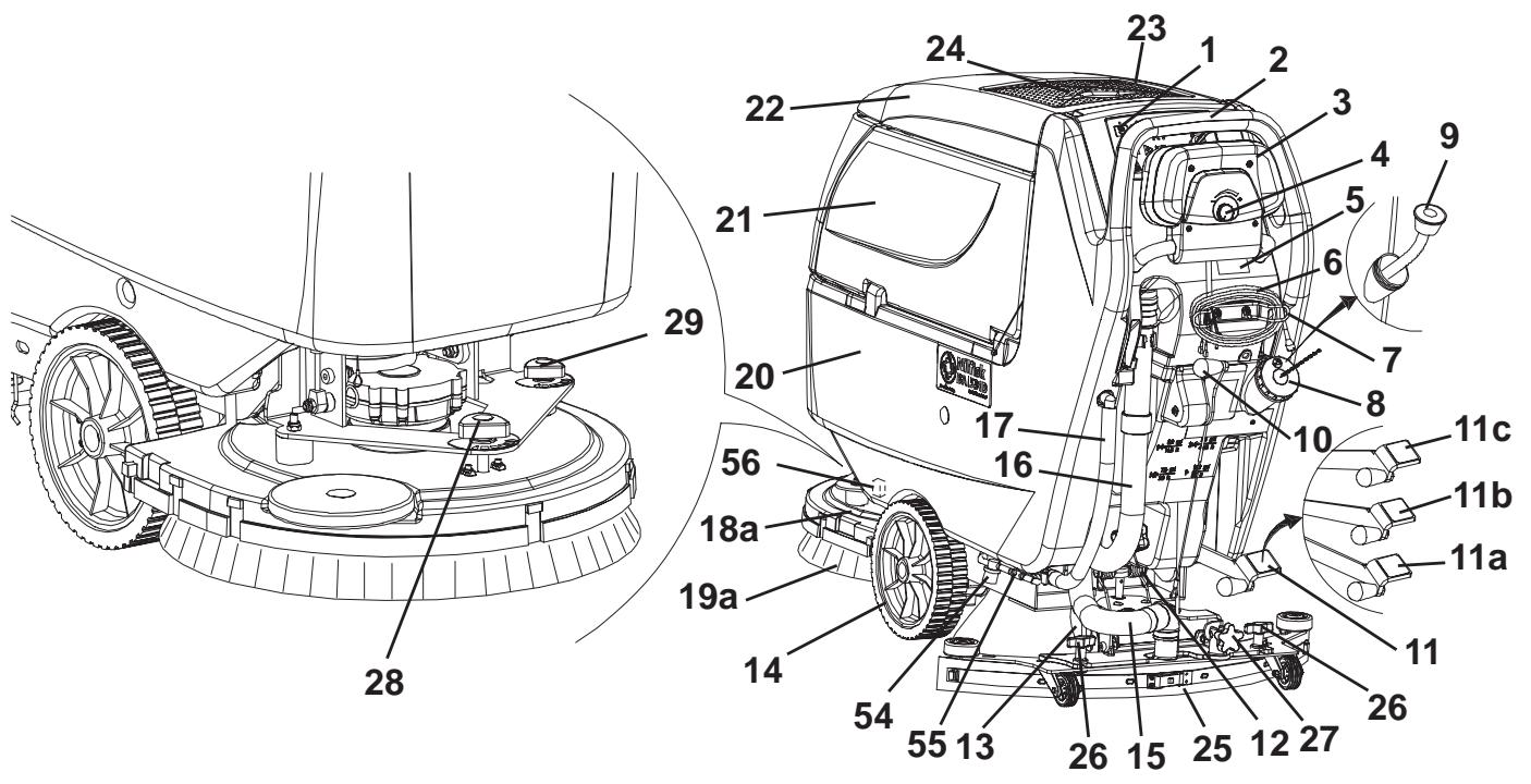
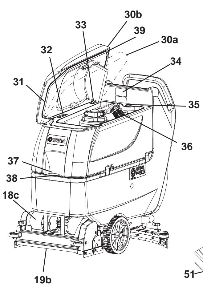
MACHINE STRUCTURE
- Control panel
- Handlebar
- Drive paddle (*)
- Drive speed adjuster (*)
- Battery charger data inspection window (optional)
- Battery charger cable (optional)
- Battery charger cable holder (optional)
- Solution/clean water rear filler neck
- Water removable filler hose (optional)
- Squeezee lifting/lowering lever
- Deck lifting/lowering pedal
11a. Pedal position when deck is lifted
11b. Pedal position when deck is lowered
11c. Extra pressure activation (optional) - Battery connector (red). This connector also works as EMERGENCY switch, to stop immediately all functions.
- Rear steering wheel
- Front wheels on fixed axle
- Squeegee vacuum hose
- Recovery water drain hose
- Solution/clean water drain and level check hose
18a. Deck with one brush/pad-holder
18b. Deck with two brushes/pad-holders
18c. Deck with two cylindrical brushes
19a. Brushes/pad-holders
19b. Cylindrical brushes - Solution/clean water tank
- Recovery water tank
- Recovery water tank cover
- Can holder
- Document retainer (optional)
- Squeezee
- Squeegee mounting handwheels
- Squeegee balance adjusting handwheel
-
Machine straight forward movement adjusting handwheel (^**)
-
Machine forward speed adjustment handwheel (^***)
30a. Recovery water tank cover (opened to be cleaned)
30b. Recovery water tank cover (completely opened) - Tank cover gasket
- Cover movable retaining plate
- Cover fixed retaining plate
- Serial number plate/technical data/conformity certification
- Plug for squeezegee vacuum hose cleaning
- Vacuum grid with automatic shut-off float
- Solution front filler neck
- Foam filter
- Compensation hole
- Recovery water tank (open)
- Tank lifting handle
- Tank safety cable
- Vacuum system motor cover
- Vacuum system motor sound-deadening filter
- Detergent tank (^**)
- Detergent tank filler plug (^**)
- Detergent tank handle (^**)
- Detergent feed hose (^**)
- Detergent tank (^**)
- Water pump (^**)
- Clean water filter (^**)
- Batteries
- Battery caps
- Solution filter (^**)
- Solution/clean water tap
- Solenoid valve
- Reference table for detergent proportioning (^**)
- Battery connection diagram
() Only for BA 551 D, BA 551 CD, BA 611 D
() Only for machines equipped with EDS - ECO Dosage Solution (optional)
(^*) Only for BA 551
S311310
CONTROL PANEL
- Brush/pad-holder and vacuum system switch
- Brush/pad-holder and vacuum system switch warning light
- Vacuum system switch
- Vacuum system switch warning light
- Brush/pad-holder release switch
- Brush/pad-holder release switch warning light
- Detergent flow control switch (^**)
- Detergent flow control switch warning light
- Hour counter (^**)
- Ignition key (0 - 1) (*)
- Battery charge indicator
81a. Charged battery warning light (green)
BA 511

S311311
81b. Semi-discharged battery warning light (yellow)
81c. Discharged battery warning light (red)
82. Washing water flow control switches
82a. Flow increase switch
82b. Flow decrease switch
82c. Washing water flow indicator
83. Forward/reverse gear paddle (^)
84. Forward/reverse gear speed adjuster ()
() Only for BA 551 D, BA 551 CD, BA 611 D
(*) Only for machines equipped with EDS - ECO Dosage Solution (optional)
BA 551 D, BA 551 CD, BA 611 D
S311312
BATTERY CHARGER DATA INSPECTION WINDOW (optional)
- Electronic battery charger
- Lead (WET) or gel (GEL) battery selector
-
Green warning light (ON: the battery charger is on and batteries are charged)
-
Yellow warning light (ON: the battery charger is on and batteries are semi-discharged)
- Red warning light (ON: the battery charger is on and it is charging the batteries)
S311313
MACHINE STRUCTURE - DESCRIPTION
Control panel (1) - It is the area where machine controls are located, see Control and Switch Description paragraph.
Handlebar (2) - Grasp it and use it to manoeuvre the machine.
Drive paddle (*) (3) - See Control and Switch Description paragraph.
Drive speed adjuster (*) (4) - See Control and Switch Description paragraph.
Battery charger data inspection window (optional) (5) - See Battery Warning Light Description paragraph.
Battery charger cable (optional) (6) - Connect it to the electrical mains to charge the batteries.
Battery charger cable holder (optional) (7) - Use it to roll up the battery charger cable when it is not in use. Fasten the cable safely.
Solution/clean water rear filler neck (8) - Open it to pour solution/clean water (^***) in the tank. Use only low-foam detergents.
Water removable filler hose (optional) (9) - For easily filling the tank with water (^**)
Squeegee lifting/lowering lever (10) - To lift or lower the squeezee.
Deck lifting/lowering pedal (11) - It has the following functions:
(11a) Pedal position when deck is lifted
(11b) Pedal position when deck is lowered
(11c) Extra pressure activation (optional)
This function is not equipped on BA 551 D and BA 611 D with cylindrical brush deck.
Battery connector (red) (12) - It connects the batteries to the machine electrical system. It must be connected to the external battery charger, when the machine is not equipped with on-board battery charger. This connector also works as EMERGENCY switch, to stop immediately all functions. If necessary, grasp the handle and disconnect the connector by pulling it strongly.
Rear steering wheel (13) - It allows the machine to steer.
Front wheels on fixed axle (14) - They bear the machine weight. Driving wheels (^*)
Squeegee vacuum hose (15) - It conveys the recovery water from the squeezegee to the recovery water tank. To easily clean it, remove the plug (35).
Recovery water drain hose (16) - It drains the recovery water from the tank.
Solution/clean water drain and level check hose (^**) (17) - It is equipped with level marks to check the solution/water level in the tank. Disconnect the upper end to drain the tank.
Brush/pad-holder deck (18a, 18b, 18c) - On the deck, brushes or pad-holders and the relevant motors are installed. Decks are easy to remove (with tools) and can be replaced with other types of deck. Three types of deck are available: with one brush/pad-holder, with two brushes/pad-holders, with two cylindrical brushes (for instructions, see the relevant paragraphs).
Brushes/pads (19a, 19b) - According to the type of deck, the machine can be equipped with: brushes, pad-holders or cylindrical brushes.
Solution/clean water tank (20) - It contains the solution/clean water (^**)
Recovery water tank (21) - It contains the recovery water collected by the squeegee and vacuumed.
Recovery water tank cover (22) - It hermetically closes the recovery water tank.
Can holder (23) - Compartment to store a can or small objects.
Document retainer (optional) (24) - Elastic retainer for documents.
Squeegee (25) - It collects the solution after scrubbing. Choose the squeezegee according to the type of deck (see the relevant paragraph).
Squeegee mounting handwheels (26) - They fasten the squeegee to the machine.
Squeegee balance adjusting handwheel (27) - To adjust the squeegee blade position.
Machine straight forward movement adjusting handwheel (^****) (28) - Turn it clockwise or counter-clockwise for machine straight forward movement.
Machine forward speed adjustment handwheel (***)(29) - Turn it clockwise or counter-clockwise to change the machine forward speed.
Recovery water tank (open) - By turning the retaining plate (32), it can be removed.
It can be opened in one of the following positions:
(30a) Opened to be cleaned.
(30b) Completely opened.
Tank cover gasket (31) - The gasket must be integral for an efficient vacuuming of the recovery water.
Cover retaining plates (32) and (33) - Turn the retaining plate (32) to remove the tank cover.
Serial number plate/technical data/conformity certification (34) - It contains the machine data.
Plug for squeegee vacuum hose cleaning (35) - Remove it to clean the vacuum hose.
Vacuum grid with automatic shut-off float (36) - Keep it clean, to avoid a stuck in the vacuum system.
Solution front filler neck (37) - For easily filling the tank with solution.
Foam filter (38) - It prevents debris or foreign materials from entering into the tank.
Compensation hole (39) - Keep it clean, for an efficient vacuuming of the recovery water.
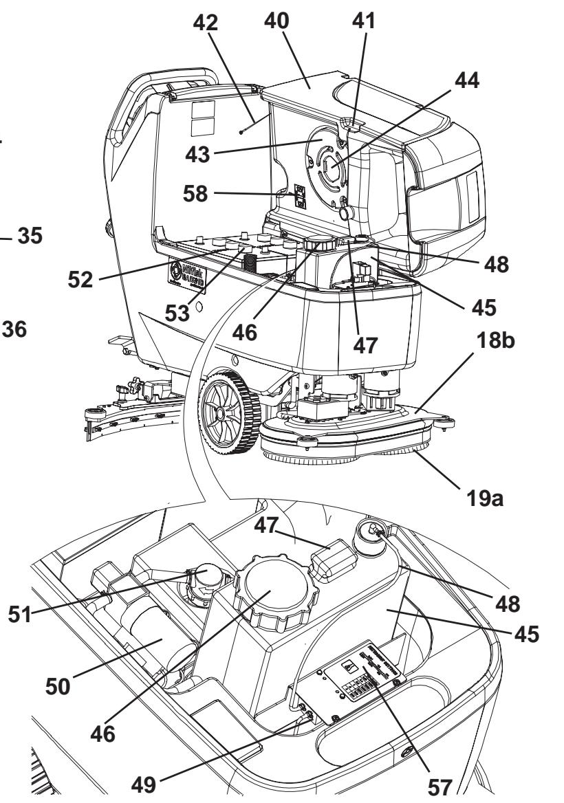
Recovery water tank (open) (40) - Empty and lift it to reach the batteries and the detergent tank.
Tank lifting handle (41) - Grasp it to lift the tank, only when it is empty.
Tank safety cable (42) - It keeps the tank opened.
Vacuum system motor cover (43) - It retains the sound-deadening filter and protects the vacuum system motor.
Vacuum system motor sound-deadening filter (44) - It protects the motor from debris and foreign material, and it deadens the vacuum system motor noise.
Detergent tank (^**) (45) - It contains the detergent that will be mixed with the clean water.
Detergent tank filler plug (^**) (46) - Open it to pour the detergent in the tank. Use only low-foam detergents.
Detergent tank handle (^**) (47) - Use it to lift/lower the tank.
Detergent feed hose (^**) (48) - It supplies the detergent to the brushes.
Detergent pump (^**) (49) - It vacuums the detergent from the tank and supplies it, together with the clean water, to the brushes.
Water pump (^**) (50) - It vacuums the water from the tank and supplies it to the brushes.
Clean water filter (^**) (51) - It filters the clean water before supplying it to the pump and brushes.
Batteries (52) - They supply current for machine operation. The machine can be equipped with lead (WET) or gel (GEL) batteries.
Battery caps (53) - WET batteries are equipped with caps for maintenance purposes.
Solution filter (^**) (54) - It filters the solution before supplying it to the solenoid valve and brushes.
Solution/clean water tap (55) - It closes the solution/clean water flow.
Solenoid valve (56) - It controls the water flow. If the machine is equipped with EDS - ECO Dosage Solution, it functions as a tap.
Reference table for detergent proportioning (^**) (57) - It indicates the percentages of detergent in the washing water. The same percentages are shown by the flow indicator (82c).
Battery connection diagram (58) - It shows how to connect the batteries.
() Only for BA 551 D, BA 551 CD, BA 611 D
() Only for machines equipped with EDS - ECO Dosage Solution (optional)
() If the machine is equipped with EDS - ECO Dosage Solution [switch (77) (optional) enabled] pour clean water in the tank, otherwise pour solution.
(^) Only for deck with one brush/pad-holder.
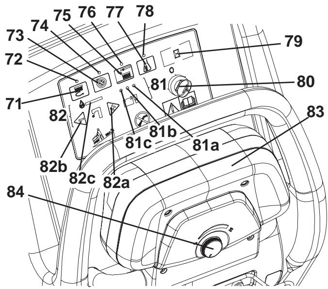
CONTROL AND SWITCH DESCRIPTION
Brush/pad-holder and vacuum system switch (71) - It turns on the brushes/pad-holders and the vacuum system. When pressed twice, it turns off the brushes/pad-holders. To turn off the vacuum system, press the switch (73).
Vacuum system switch (73) - It turns the vacuum system on and off.
Brush/pad-holder release switch (75) - It releases the brushes/pad-holders, and it can be pressed only when the brushes/pad-holders are off.
Detergent flow control switch (^**) (77) - It turns the EDS - ECO Dosage Solution on and off and it allows to change the detergent concentration.
Ignition key (*) (80) - It turns the control panel on and off.
Washing water flow control switches (82) - To control the detergent quantity supplied to the brushes.
Flow increase switch (82a) - It increases the water quantity supplied to the brushes.
Flow decrease switch (82b) - It decreases the water quantity supplied to the brushes.
Washing water flow indicator (82c) - It shows the water quantity supplied to the brushes.
Drive paddle (*) (83) - Push it forward to move the machine forward, push it backwards to move the machine in reverse. The brushes/pad-holders and the water flow turn on only when the paddle is pushed in either directions. When the paddle is released, the brushes/pad-holders turn off.
Forward/reverse gear speed adjuster (*) (84) - It adjusts the machine maximum speed, when the drive paddle is pushed to the end of stroke.
() Only for BA 551 D, BA 551 CD, BA 611 D
(*) Only for machines equipped with EDS - ECO Dosage Solution (optional)
WARNING LIGHT AND INDICATOR DESCRIPTION
Brush/pad-holder and vacuum system switch warning light (72) - When the warning light turns on, it means that the relevant function is activated.
Vacuum system switch warning light (74) - When the warning light turns on, it means that the relevant function is activated.
Brush/pad-holder release switch warning light (76) - When the warning light turns on, it means that the relevant function is activated.
Detergent flow control switch warning light (78) - When the warning light turns on, it means that the relevant function is activated.
Hour counter (optional) (79) - It shows the machine working hours.
BATTERY WARNING LIGHT DESCRIPTION
Battery charge indicator (81) - It shows battery autonomy.
Green warning light (81a) - When it is on, the battery are charged (residual autonomy depends on battery capacity and working conditions.)
Yellow warning light (81b) - When it is on, the battery are semi-discharged (residual autonomy is 10 minutes approximately.)
Red warning light (81c) - When it is on, the battery are discharged (the autonomy is over, the batteries must be recharged (see the procedure in the relevant paragraph.))
ACCESSIONS/OPTIONS
In addition to the standard components, the machine can be equipped with the following accessories/options, according to the machine specific use:
- GEL batteries
- Electronic battery charger
- Brushes and cylindrical brushes of different materials
- Pads of different materials
- Polyurethane squeegee blades
- EDS - ECO Dosage Solution
- Front and rear wheels of different materials
- Hour counter
- Solution/clean water removable filler hose
For further information concerning the optional accessories, contact an authorised Service Centre or Retailer.
TECHNICAL DATA
General technical data
| Model | BA 551(1 brush/pad-holder, without drive system) | BA 551 D(1 brush/pad-holder, with drive system) | BA 551 CD(2 cylindrical brushes, with drive system) | BA 611 D(2 brushes/pad-hol ders, with drive system) |
| Machine height | 1,088 mm | |||
| Solution/clean water tank capacity | 58 litres | |||
| Recovery water tank capacity | 60 litres | |||
| Front wheel diameter | 250 mm | |||
| Front wheel specific pressure on the ground | 1.2 N/mm2 | |||
| Rear wheel diameter | 100 mm | |||
| Vacuum system motor power | 330 W | |||
| Drive system motor power | — | 200 W | ||
| Drive speed (variable) | — | 0 to 5.6 km/h | ||
| Gradeability | 2% | |||
| Sound pressure level (at the operator's position) | 65.8 dB(A) | |||
| Standard batteries | GEL: (2 x 12 V) 24 V 110 Ah / 5 h | |||
| Battery compartment size (width x length x height) | 350 x 350 x 300 mm | |||
| Vacuum system circuit capacity | 1,055 mm H2O | |||
Technical data for machines with brush/pad-holder deck
| Model | BA 551(1brush/pad-holder, without drive system) | BA 551 D(1brush/pad-holder, with drive sys-tem) | BA 611 D(2brushes/pad-holders, with drive system) |
| Cleaning width | 530 mm | 530 mm | 610 mm |
| Squeezeeep width | 760 mm | 810 mm | |
| Machine maximum length | 1,323 mm | 1,311 mm | |
| Machine width without squeezegee | 541 mm | 646 mm | |
| Brush diameter | 530 mm | 305 mm | |
| Weight without batteries and with empty tanks | 88 kg | 102 kg | |
| Maximum weight with batteries and full tanks | 236 kg | 250 kg | |
| Brush motor power | 480 W | 350 W | |
| Brush speed | 153 rpm | 230 rpm | |
| Brush/pad-holder pressure with extra-pressure turned off | 20.5 kg | ||
| Brush/pad-holder pressure with extra-pressure function turned on | 27.8 kg | ||
Technical data for machines with cylindrical brush deck
| Model | BA 551 CD (2 cylindrical brushes, with drive system) |
| Cleaning width | 510 mm |
| Squeezeeep width | 760 mm |
| Machine maximum length | 1,253 mm |
| Machine width without squeezegee | 575.5 mm |
| Cylindrical brush size (diameter x length) | 110 x 485 mm |
| Weight without batteries and with empty tanks | 112 kg |
| Maximum weight with batteries and full tanks | 260 kg |
| Brush motor power | 400 W |
| Cylindrical brush speed | 570 rpm |
| Cylindrical brush pressure | 26.5 kg |
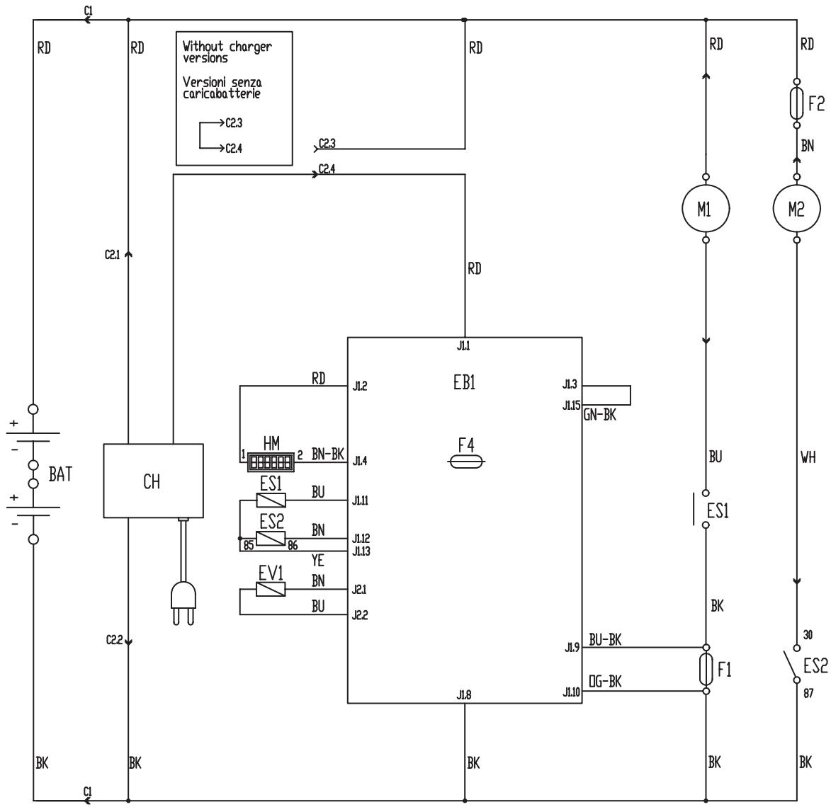
WIRING DIAGRAM FOR BA 551
BAT: 24 V battery
C1: Battery connector
C2: Battery charger connector
CH: Battery charger (optional)
CS: Deck connector
EB1: Function electronic board
ES1: Brush electromagnetic switches
ES2: Vacuum system relay
EV1: Water solenoid valve
F1: Deck fuse
F2: Vacuum system fuse
F4: Signal circuit fuse
HM: Hour counter (optional)
M1: Brush/pad-holder motor
M2: Vacuum system motor
Colour codes
BK: Black
BU: Blue
BN: Brown
GN: Green
GY: Grey
OG: Orange
PK: Pink
RD: Red
VT: Violet
WH: White
YE: Yellow
S311314
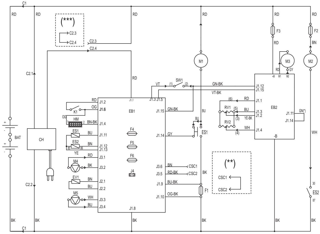
WIRING DIAGRAM FOR BA 551 D, BA 551 CD AND BA 611 D
BAT: 24 V battery
C1: Battery connector
C2: Battery charger connector
CH: Battery charger (optional)
CSC: Cylindrical brush deck secondary connector
EB1: Function electronic board
EB2: Drive system electronic board
ES1: Brush electromagnetic switches
ES2: Vacuum system relay
EV1: Detergent solenoid valve (optional)
F1: Deck fuse
F2: Vacuum system fuse
F3: Drive system fuse
F4: Signal circuit fuse
F5: Brush/pad-holder release fuse
F6: Pump fuse
HM: Hour counter (optional)
K1: Ignition key
M1: Brush/pad-holder motor
M2: Vacuum system motor
M3: Drive system motor
M4: Water pump (optional)
M5: Detergent pump (optional)
RV1: Speed potentiometer
RV2: Maximum speed potentiometer
SW1: Brush/drive system enabling microswitch
() Only for machine with wheel diameter of 250 mm
() Only for machines with cylindrical brush deck
(^*) Only for machines without on-board battery charger
Colour codes
BK: Black
BU: Blue
BN: Brown
GN:Green
GY: Grey
OG: Orange
PK: Pink
RD: Red
VT: Violet
WH: White
S311315
USE

WARNING!
On some points of the machine there are some adhesive plates indicating:
DANGER
-WARNING
- CAUTION
CONSULTATION
While reading this Manual, the operator must pay particular attention to the symbols shown on the plates. Do not cover these plates for any reason and immediately replace them if they are damaged.
BATTERY CHECK/SETTING ON A NEW MACHINE

WARNING!
The electric components of the machine can be seriously damaged if the batteries are either improperly installed or connected. The batteries must be installed by qualified personnel only. Set the function electronic board and the battery charger (optional) according to the type of batteries used (WET or GEL). Check the batteries for damage before installation.
Disconnect the battery connector and the battery charger plug.
Handle the batteries with great care.
Install the battery terminal protection caps supplied with the machine.
The machine requires two 12V batteries, connected according to the diagram (58).
The machine can be supplied in one of the following modes:
a) Batteries (WET or GEL) already installed and ready to be used
- Check that the batteries are connected to the machine with the connector (12).
- (Only for BA 551 D, BA 551 CD, BA 611 D): Insert the ignition key (80) and turn it to "l" position.
(Only for BA 551): Turn on the machine by pressing the switch (71) and/or (73).
If the green warning light (81a) turns on, the batteries are ready to be used.
If the yellow or red warning light (81b or 81c) turns on, the batteries must be charged (see the procedure in the
Maintenance chapter).
b) Batteries (WET) installed on the machine, but without electrolyte
- Open the cover (22) and check that the recovery water tank (21) is empty, otherwise empty it with the drain hose (16).
- Grasp the handle (41) and carefully lift the tank (40).
- Remove the caps (53) of the batteries (52).

WARNING!
Pay attention when using sulphuric acid, as it is corrosive. If it comes in contact with skin or eyes, rinse thoroughly with water and consult a physician.
Batteries have to be filled in a well-ventilated area. Wear protective gloves.
- Fill up the battery cells with sulphuric acid for batteries (density 1.27 to 1.29kg at 25^ ) in accordance with the instructions shown in the Battery Manual. The correct quantity of sulphuric acid is shown in the Battery Manual.
- To avoid damaging the floor, dry with a cloth both acid and water on the top of the batteries after charge.
- Let the batteries rest and fill in with sulphuric acid in accordance with the instructions shown in the Battery Manual.
- Charge the batteries (see the procedure in the Maintenance chapter).
c) Without batteries
- Buy appropriate batteries (see the Technical Data paragraph).
For battery choice and installation, apply to qualified battery Retailers. - Set the machine and the battery charger (if equipped) according to the type of batteries installed (WET or GEL), according to the procedure shown in the following paragraph.
BATTERY INSTALLATION AND BATTERY TYPE SETTING (WET OR GEL)
According to the type of batteries (WET or GEL), set the electronic board of the machine and of the battery charger (if equipped), according to the following procedure:
Machine setting (only for BA 551)
- Press the switch (71) or (73) and pay attention to the following in the very first seconds of machine operation:
- If the green warning light (81a) is flashing, the machine is set to GEL.
If the red warning light (81c) is flashing, the machine is set to WET. - If the setting is to be changed, perform the following procedure.
- Turn off the machine by pressing the switch (71) and/or (73).
- Press and hold the switches (71) and (73) at the same time.
- Release the switches (71) and (73) at least 8 seconds after starting the machine.
- Within 3 seconds, press the switch (73) again for a few seconds and check that the warning light for the required setting is flashing (as shown in step 1).
Machine setting (only for BA 551 D, BA 551 CD, BA 611 D)
- Turn the ignition key (80) to "l" position and pay attention to the following in the very first seconds of machine operation:
- If the green warning light (81a) is flashing, the machine is set to GEL.
If the red warning light (81c) is flashing, the machine is set to WET. - If the setting is to be changed, perform the following procedure.
- Turn off the machine by turning the ignition key (80) to "0" position.
- Press and hold the switches (71) and (73) at the same time, then turn the ignition key (80) to "I".
- Release the switches (71) and (73) at least 8 seconds after starting the machine.
- Within 3 seconds, press the switch (73) again for a few seconds and check that the warning light for the required setting is flashing (as shown in step 1).
Battery charger setting (for machines with on-board battery charger)
- Remove the battery charger data inspection window screws (A, Fig. 1).
- Remove the window (B).
- Turn the battery charger selector (C) to WET position for lead batteries, or to GEL position for gel batteries.
- Install the window (B) and tighten the screws (A).
Battery installation
- Open the cover (22) and check that the recovery water tank (21) is empty, otherwise empty it with the drain hose (16).
- Grasp the handle (41) and carefully lift the tank (40).
- Install the batteries.
Battery charging
- Charge the batteries (see the procedure in the Maintenance chapter).
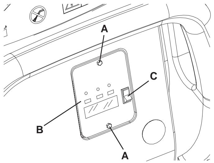
Figure 1
S311316
BEFORE MACHINE START-UP
Deck installation/removal
The machine can be equipped with either the brush/pad-holder deck (18a and 18b) or the cylindrical brush deck (18c). For deck installation/removal see the procedure in the Maintenance chapter.

NOTE
When the deck is installed/removed, it could be necessary to replace the squeegee, because they must have the same width. For correct matching of deck and squeegee, see the Squeegee Installation paragraph.
Brush/pad-holder installation/removal
- According to the kind of cleaning to be carried out, the machine can be equipped either with brushes (A, Fig. 2) or pad-holders (B) with pads (C) together with the appropriate deck.
- (Only for BA 551 D, BA 551 CD, BA 611 D): Turn the ignition key (80) to "0" position. (Only for BA 551): Turn off the machine by pressing the switch (71) and/or (73).
- If equipped, turn the speed adjuster (84) to idle by turning it counter-clockwise.
- Place the brushes (A) or the pad-holders (B) under the appropriate deck (18a) or (18b).
- Lower the deck on the brushes/pad-holders by pressing the pedal (11).
- (Only for BA 551 D, BA 551 CD, BA 611 D): Turn the ignition key (80) to "l" position.
- Press the brush/pad-holder and vacuum system switch (71).
- Slightly press the paddle (83) forward to engage the brushes/pad-holders, then release it. If necessary, repeat the procedure until the brushes/pad-holders are engaged.
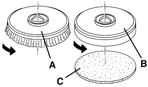
Figure 2
S311317

WARNING!
(Only for BA 551 D, BA 551 CD, BA 611 D): Do not press the paddle (83) completely, otherwise the machine will start moving.
A slight pressure on the paddle (83) is enough to engage the brushes/pad-holders and to turn on the relevant motors.
- To remove the brushes/pad-holders, the deck must be lifted by pressing the pedal (11), then press the switch (75) (if equipped) and wait for the brush/pad-holder to fall on the floor.
(Only for BA 551 D, BA 551 CD, BA 611 D): Turn the ignition key (80) to "0" position.
(Only for BA 551): Press the switch (71).
If the machine is not equipped with the automatic release system (switch 75), manually remove the brush/pad-holder from the hub, by turning it in the opposite direction to the normal rotation direction.
Types of brushes available
| 305 mm-models | 530 mm-models |
| 08603842 - Prolene | 08837025 - Prolene |
| 08603872 - Midlite Grit 180 | 08837028 - Midlite Grit 180 |
| 08603873 - Midgrit 240 | 08837029 - Midgrit 240 |
| 08603874 - Prolite | 08837026 - Prolite |
| 08603875 - Union Mix | 08837027 - Union Mix |
Brush/pad application guide (suggestions only)
| Models | Midlite Grit 180 | Midgrit 240 | Prolene | Prolite | Union Mix |
| General cleaning: | |||||
| Concrete | |||||
| Terrazzo floor | |||||
| Ceramic tiles/quarrystones | |||||
| Marble | |||||
| Vinyl tiles | |||||
| Rubber tiles | |||||
| Polishing: | |||||
| Rubber tiles | |||||
| Marble | |||||
| Vinyl tiles | |||||
Cylindrical brush installation/removal (only for BA 551 CD)
- Turn the ignition key (80) to "0" position.
- Lift the cylindrical brush deck by pressing the pedal (11).
- Remove the handwheels (A, Fig. 3) and the lids (B) by pushing them downwards and pressing on the handwheels.
- Install the cylindrical brushes (C).
The cylindrical brushes can be installed on either sides.
- Install the lids (B) and fasten them with the handwheels (A).
- To remove the cylindrical brushes, carry out steps 1 to 5 in the reverse order.
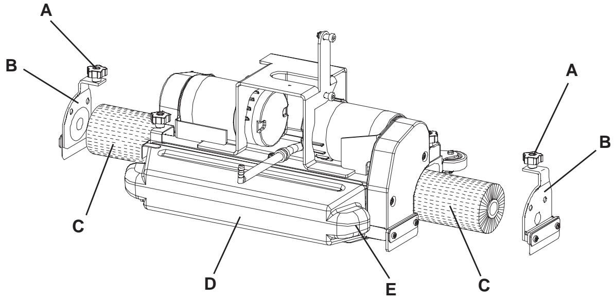
Figure 3
S311318
Types of cylindrical brushes available
| 485 mm-models |
| 909 5823 000 - Polypropylene 0.40 |
| 909 5825 000 - Hard nylon 0.60 |
| 909 5824 000 - Soft nylon 0.45 |
Cylindrical brush application guide (suggestions only)
| Models | Polypropylene 0.40 | Hard nylon 0.60 | Soft nylon 0.45 |
| General cleaning: | |||
| Concrete | |||
| Terrazzo floor | |||
| Ceramic tiles/quarrystones | |||
| Marble | |||
| Vinyl tiles | |||
| Rubber tiles | |||
Squeezegee installation
- Install the squeegee (25) and fasten it with the handwheels (26), then connect the vacuum hose (15) to the squeegee.
- With the handwheel (27), adjust the squeezegee so that the rear blade - in all its length - touches the floor and the front blade is slightly detached from the floor.
Guide to match squeezees and brush/pad-holder decks
| Deck model | Squeegee model |
| Deck with one brush (18a), brush diameter: 530 mm | Aluminium (Fig. 6), width 760 mm |
| Deck with two brushes (18b), brush diameter: 305 mm | Steel (Fig. 5), width 810 mm |
| Deck with two cylindrical brushes (18c), brush length: 485 mm | Aluminium (Fig. 6), width 760 mm |
Solution or washing water tank filling

NOTE
If the machine is equipped with EDS - ECO Dosage Solution [switch (77) (optional) enabled] pour clean water in the tank, otherwise pour solution.
- Open the filler neck (8).
- (For machines without EDS - ECO Dosage Solution)
Fill the tank (20) with a solution suitable for the work to be carried out.
Do not fill the solution tank completely, leave a few centimetres from the edge.
Always follow the dilution instructions on the container label on the chemical product used to create the solution.
The solution temperature must not exceed 40^

CAUTION!
Use only low-foam and non-flammable detergents, intended for automatic scrubber applications.
(For machines with EDS - ECO Dosage Solution)
Fill the tank (20) with clean water.
Do not fill the clean water tank completely, leave a few centimetres from the edge.
The water temperature must not exceed 40^ .
Detergent tank filling (for machines with EDS - ECO Dosage Solution)
- Open the cover (22) and check that the recovery water tank (21) is empty, otherwise empty it with the drain hose (16).
- Grasp the handle (41) and carefully lift the tank (40).
- Open the plug (46).
- Fill the tank (45) with a detergent suitable for the work to be carried out (highly concentrated detergent).
Do not fill the detergent tank completely, leave a few centimetres from the edge.

CAUTION!
Use only low-foam and non-flammable detergents, intended for automatic scrubber applications.

NOTE
If the detergent hose (48) is empty (in case of new system, system emptied for cleaning, etc.), in order to fill the hose quickly, it may be useful to drain the EDS - ECO Dosage Solution once or several times (see the procedure in the Maintenance chapter).
MACHINE START AND STOP
Starting the machine
- Prepare the machine as shown in the previous paragraph.
- (Only for BA 551 D, BA 551 CD, BA 611 D): Turn the ignition key (80) to "l" position.
(Only for BA 551): Turn on the machine by pressing the switch (71) and/or (73).
Check that the green warning light (81a) turns on (charged batteries).
If the yellow or red warning light (81b or 81c) turns on, turn the ignition switch back to "0" position and charge the batteries (see the procedure in the Maintenance chapter).
-
Drive the machine to the working area:
-
By pushing it with the hands on the handlebar (2) (only for BA 551).
- By starting it with the hands on the handlebar (2) and pushing the paddle (83) forward to move forward, and backwards to move in reverse (only for BA 551 D, BA 551 CD, BA 611 D).
The maximum forward speed can be adjusted with the adjuster (84).
- Lower the squeegee (25) with the lever (10).
- Lower the brush/pad-holder deck by pressing the pedal (11).
- Press the brush/pad-holder and vacuum system switch (71).
- Press the washing water flow control switches (82) as necessary, depending on the type of cleaning to be carried out.
- Start cleaning, by moving the machine as shown in step 3. If necessary, adjust the maximum speed with the adjuster (84).
Stopping the machine
- Stop the machine with the handlebar (2) (only for BA 551).
- Stop the machine by releasing the paddle (83) (only for BA 551 D, BA 551 CD, BA 611 D).
- Turn off the brushes and the vacuum system by pressing the switches (71 and 73).
- Lift the brush/pad-holder deck by pressing the pedal (11).
- Lift the squeegee (25) with the lever (10).
- Make sure that the machine cannot move independently.
MACHINE OPERATION (SCRUBBING/DRYING)
- Start the machine as shown in the previous paragraph.
- If necessary, press the washing water flow control switches (82) as necessary, depending on the type of cleaning to be carried out.
- If necessary, stop the machine and adjust the balancing handwheel (27) of the squeezegee (25).

CAUTION!
To avoid any damage to the floor surface, turn off the brushes/pad-holders when the machine stops in one place, especially when the extra pressure function is on.
Detergent flow adjustment
(For machines with EDS - ECO Dosage Solution)
To check the actual setting of the detergent percentage to be added to the washing water, perform the following procedure:
- Turn off the flow control switch (A, Fig. 4) [the warning light (B) must be off].
- Press and hold the flow control switch (A). 3 seconds after pressing the switch, the indicator (C) turns on, thus indicating the percentage, as shown in the figure.
To change the actual setting of the detergent percentage to be added to the washing water, perform the following procedure:
- Turn off the flow control switch (A, Fig. 4) [the warning light (B) must be off].
- Press and hold the flow control switch (A) until the warning light (B) flashes.
- Release the switch (A). Press it again shortly, to go to the next percentage shown by the indicator (C); repeat the procedure until the desired setting is reached.
- Wait for the warning light (B) to turn off and for the indicator (C) to show the washing water flow: the new percentage is now set.

NOTE
Detergent percentage setting is stored into memory, even if the machine is turned off.
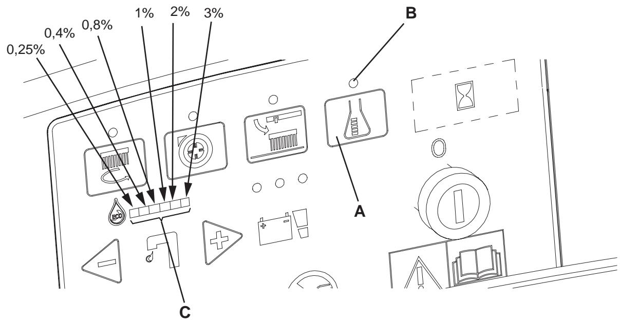
Figure 4
S311319
Working with brush/pad-holder extra pressure function turned on
- If the floor proves to be particularly difficult to clean, it is possible to turn on the brush/pad-holder extra pressure function by pressing the pedal (11) to position (11c).

CAUTION!
When the cylindrical brush deck (18c) is installed, the extra pressure function is not enabled.
Battery discharge during operation
- Until the green warning light (81a) stays on, the batteries allow the machine to work normally.
When the green warning light (81a) turns off, and the yellow warning light (81b) turns on, it is advisable to charge the batteries, because the residual autonomy will last for a few minutes (depending on battery characteristics and work to be performed).
When the red warning light (81c) turns on, the autonomy is over. After a few seconds, the brushes/pad-holders are automatically tuned off, while the vacuum system and (only for BA 551 D, BA 551 CD, BA 611 D) the drive system stay on, to finish drying the floor and drive the machine to the appointed recharging area.

CAUTION!
Do not use the machine with discharged batteries, to avoid damaging the batteries and reducing the battery life.
TANK EMPTYING
An automatic float shut-off system (36) turns off the vacuum system when the recovery water tank (21) is full.
The vacuum system deactivation is signalled by a sudden increase in the vacuum system motor noise frequency.

CAUTION!
If the vacuum system turns off accidentally (for example, when the float is activated because of a sudden machine movement), to resume the operation: turn off the vacuum system by pressing the switch (73), then open the cover (22) and check that the float inside the grid (36) has gone down to the water level. Then close the cover (22) and turn on the vacuum system by pressing the switch (73).
When the recovery water tank (21) is full, empty it according to the following procedure.
Recovery water tank emptying
- Stop the machine.
- Lift the brush/pad-holder deck by pressing the pedal (11).
- Lift the squeegee (25) with the lever (10).
- Drive the machine to the appointed disposal area.
- Empty the recovery water tank with the hose (16). After working, rinse the tank with clean water. Use the removable hose (9) (if equipped).
Solution/clean water tank emptying
- Perform steps 1 to 4.
- Empty the solution tank with the hose (17). After working, rinse the tank with clean water.
Cylindrical brush debris container emptying (only for cylindrical brush deck)
- Stop the machine.
- Lower the cylindrical brush deck and remove the debris container (D, Fig. 3) by pulling it on one side with the handle (E).
- Empty and wash the debris container (D), and then install it by engaging it on the retainers.
AFTER USING THE MACHINE
After working, before leaving the machine:
- Remove the brushes/pad-holders according to the procedure shown in the relevant paragraph.
- Empty the tanks (20 and 21) and the debris container (D, Fig. 3) as shown in the relevant paragraph.
- Perform the daily maintenance procedures (see the Maintenance chapter).
- Store the machine in a clean and dry place, with the brushes/pad-holders and the squeegee lifted or removed.
MACHINE LONG INACTIVITY
If the machine is not going to be used for more than 30 days, proceed as follows:
- Perform the procedures shown in After Machine Use paragraph.
- Disconnect the battery connector (12).
FIRST PERIOD OF USE
After the first 8 hours, check the machine fastening and connecting parts for proper tightening and check the visible parts for integrity and leakage.
MAINTENANCE
The lifespan of the machine and its maximum operating safety are ensured by correct and regular maintenance. The following table provides the scheduled maintenance. The intervals shown may vary according to particular working conditions, which are to be defined by the person in charge of the maintenance.

WARNING!
The procedures must be carried out with the machine off and the battery disconnected.
Moreover, read carefully the instructions in the Safety chapter before performing any maintenance procedure.
All scheduled or extraordinary maintenance procedures must be performed by qualified personnel, or by an authorised Service Center.
This Manual describes only the easiest and most common maintenance procedures.
For other maintenance procedures shown in the Scheduled Maintenance Table, refer to the Service Manual that can be consulted at any Service Center.
SCHEDULED MAINTENANCE TABLE
| Procedure | Daily, after machine use | Weekly | Every six months | Yearly |
| Battery charging | ||||
| Squeegee cleaning | ||||
| Brush/pad cleaning | ||||
| Tank and vacuum grid with float cleaning, and cover gasket check | ||||
| Squeegee blade check and replacement | ||||
| Solution/clean water filter cleaning | ||||
| Vacuum system motor cleaning | ||||
| WET battery fluid level check | ||||
| Screw and nut tightening check | (1) | |||
| Brush/pad-holder motor carbon brush check or replacement | (2) | |||
| Vacuum system motor carbon brush check or replacement | (2) | |||
| Drive system motor carbon brush check or replacement (only for BA 551 D, BA 611 D) | (2) |
(1): And after the first 8 working hours.
(2): This maintenance procedure must be performed by an authorized Nilfisk-Advance Service Center.
CHARGING THE BATTERIES

NOTE
Charge the batteries when the yellow or red warning light (81b or 81c) turns on, or at the end of every working cycle.

CAUTION!
Keeping the batteries charged make their life last longer.

CAUTION!
When the batteries are discharged, charge them as soon as possible, as that condition makes their life shorter. Check for battery charge at least once a week.

CAUTION!
If the machine is not equipped with on-board battery charger, choose an external battery charger suitable for the type of batteries installed.

WARNING!
WET battery charging produces highly explosive hydrogen gas. Charge the batteries in well-ventilated areas and away from naked flames. Do not smoke while charging the batteries. Keep the tank assembly open while charging the batteries.

WARNING!
Pay careful attention when charging the batteries as there may be battery fluid leakages. The battery fluid is corrosive. If it comes in contact with skin or eyes, rinse thoroughly with water and consult a physician.
Preliminary operations
- Open the cover (22) and check that the recovery water tank (21) is empty, otherwise empty it with the drain hose (16).
- Drive the machine to the appointed recharging area.
- (Only for BA 551 D, BA 551 CD, BA 611 D): Turn the ignition key (80) to "0" position.
(Only for BA 551): Turn off the machine by pressing the switch (71) and/or (73).
- Grasp the handle (41) and carefully lift the tank (40).
-
For WET batteries only:
-
Check the level of electrolyte inside the batteries (52); if necessary, top up through the caps (53).
-
Then leave all the caps (53) open for battery charging.
If necessary, clean the upper surface of the batteries. -
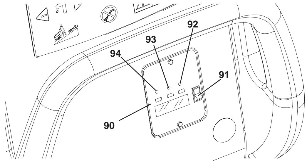
Charge the batteries according to one of the following procedures, depending on the presence of the battery charger (90).
Charging the batteries with an external battery charger
- Check that the external battery charger is suitable by referring to the relevant Manual. The battery charger voltage rating must be 24V .
- Disconnect the battery connector (12) and connect it to the external battery charger.
- Connect the battery charger to the electrical mains.
- After charging, disconnect the battery charger from the electrical mains and from the battery connector (12).
- (For WET batteries only) Check the level of electrolyte inside the batteries and close all the caps (53).
- Connect the battery connector (12) to the machine.
- Grasp the handle (41) and carefully lower the tank (40).
Battery charging with (optional) battery charger installed on the machine
- Connect the battery charger cable (6) to the electrical mains (the electrical mains voltage and frequency must be compatible with the battery charger values shown on the machine serial number plate (34)).
When the battery charger is connected to the electrical mains, all machine functions are automatically cut off.
If the red warning light (94) on the battery charger control panel stays on, the battery charger is charging the batteries.
- When the green warning light (92) turns on, the battery charging is completed.
- When the battery charging is completed, disconnect the battery charger cable (6) from the electrical mains and wind it round its housing (7).
- Grasp the handle (41) and carefully lower the tank (40).

NOTE
For further information about the battery charger (90) operation, see the relevant Manual.
MACHINE WORKING HOUR CHECK
(Only if the machine is equipped with hour counter)
- (Only for BA 551 D, BA 551 CD, BA 611 D): Turn the ignition key (80) to "I" position.
- Press the switch (73) and read on the hour counter (79) the total number of working hours (scrubbing/drying) performed by the machine.
- Press the switch (73) again.
- Turn the ignition key (80) to "0" position.
SQUEEGEE CLEANING

NOTE
The squeegee must be clean and its blades must be in good conditions in order to get a good drying.

CAUTION!
It is advisable to use protective gloves when cleaning the squeegee because there may be sharp debris.
- Drive the machine on a level floor.
- (Only for BA 551 D, BA 551 CD, BA 611 D): Turn the ignition key (80) to "0" position.
(Only for BA 551): Turn off the machine by pressing the switch (71) and/or (73).
- Lower the squeegee (25) with the lever (10).
- Loosen the handwheels (26) and remove the squeegee (25).
- Disconnect the vacuum hose (15) from the squeegee.
- Clean the steel squeegee (Fig. 5) or the aluminium squeegee (Fig. 6). Clean the compartments (A, Fig. 5 or 6) and the hole (B) especially. Check the front blade (C) and the rear blade (D) for integrity, cuts and tears; otherwise replace them (see the procedure in the following paragraph).
- Install the squeegee in the reverse order of removal.
SQUEEGEE BLADE CHECK AND REPLACEMENT
- Clean the steel squeezegee (Fig. 5) or the aluminium squeezegee (Fig. 6), according to the procedure shown in the previous paragraph.
-
Check that the edges (E, Fig. 5 or 6) of the front blade (C) and the edges (F) of the rear blade (D) lay down on the same level, along their length; otherwise adjust their height according to the following procedure:
-
Release the tie rod (G, Fig. 5 or 6) and loosen the wing nuts (H, Fig. 5), or disengage the retainers (M, Fig. 6) and adjust the rear blade (D, Fig. 5 or 6), then tighten the wing nuts, or engage the retainers, and then engage the tie rod.
-
Loosen the handwheels (I) and adjust the front blade (C, Fig. 5 or 6); then tighten the handwheels.
-
Check the front blade (C, Fig. 5 or 6) and rear blade (D) for integrity, cuts and tears; if necessary replace them according to the following procedure. Check that the front corner (J) of the rear blade is not worn; otherwise, overturn the blade to replace the worn corner with an integral one. If the other corners are worn too, replace the blade according to the following procedure:
-
Release the tie rod (G), remove the wing nuts (H) or disengage the retainers (M), remove the retaining strip (K), then replace/overturn the rear blade (D). Install the blade in the reverse order of removal.
- Unscrew the handwheels (I) and remove the retaining strip (L), then replace the front blade (C). Install the blade in the reverse order of removal.
After the blade replacement (or overturning), adjust the height as shown in the previous step.
- Connect the vacuum hose (15) to the squeegee.
- Install the squeegee (25) and screw down the handwheels (26).
- If necessary, adjust the squeegee balance adjusting handwheel (27).
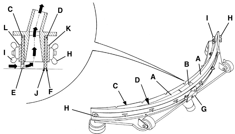
Figure 5
S311320
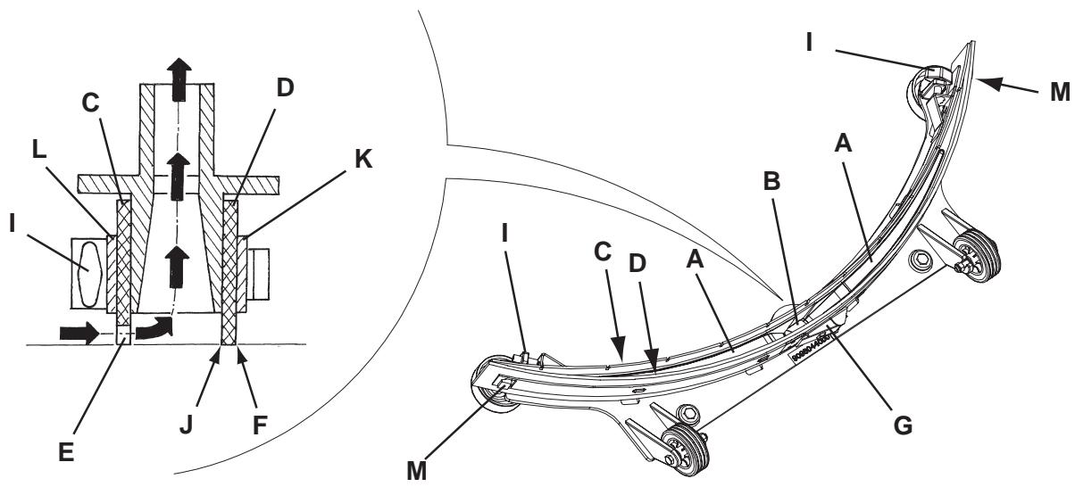
Figure 6
S311326
BRUSH/PAD CLEANING

CAUTION!
It is advisable to wear protective gloves when cleaning the brushes/pads/cylindrical brushes because there can be sharp debris.
- Remove the brushes/pads from the machine, as shown in the Use chapter.
- Clean and wash the brushes/pads with water and detergent.
- Check that the brush/pads are integral and not excessively worn; otherwise replace them.
- On the machines equipped with the cylindrical brush deck, remove the debris container (D, Fig. 3) by pulling it on one side with the handle (E).
Empty and wash the debris container (D), and then install it by engaging it on the retainers.
TANK AND VACUUM GRID WITH FLOAT CLEANING, AND COVER GASKET CHECK
- Drive the machine to the appointed disposal area.
- (Only for BA 551 D, BA 551 CD, BA 611 D): Turn the ignition key (80) to "0" position.
(Only for BA 551): Turn off the machine by pressing the switch (71) and/or (73).
- Open the cover (A, Fig. 7) to washing position (L).
- Wash with clean water the cover (A), the tanks (B and C) and the vacuum grid with automatic shut-off float (D).
Drain the water from the tanks with the hoses (16 and 17).
- If necessary, release the retainers (E) and open the grid (D), recover the float (F), clean all the components and then reinstall them.
- Check the tank cover gasket (G) for integrity.

NOTE
The gasket (G) creates vacuum in the tank that is necessary for vacuuming the recovery water.
If necessary replace the gasket (G) by removing it from its housing (H). When assembling the new gasket, install the joint (I) in the rear central area, as shown in the figure.
- Check that the bearing surface (J) of the gasket (G) is integral and adequate for the gasket itself.
- Check the compensation hole (K) for clogging, and clean it if necessary.

NOTE
The hole (K), allowing to compensate the air in the cover interspaces, contributes to create vacuum in the tank.
- Close the cover (A).
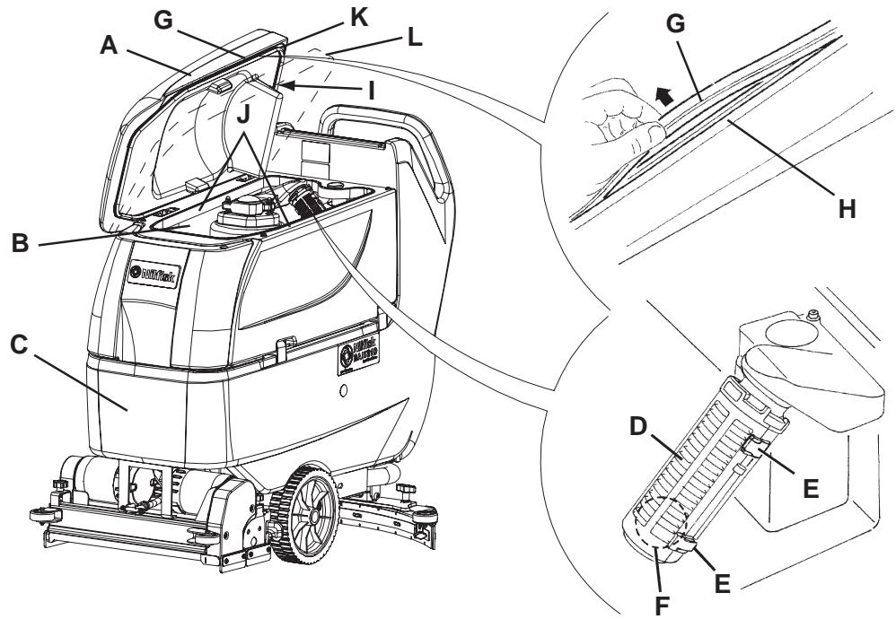
Figure 7
S311321
VACUUM SYSTEM MOTOR FILTER CLEANING
- Drive the machine on a level floor.
- (Only for BA 551 D, BA 551 CD, BA 611 D): Turn the ignition key (80) to "0" position.
(Only for BA 551): Turn off the machine by pressing the switch (71) and/or (73). - Open the recovery water tank.
- If necessary, drain the water from the tank in order to make the filter visible.
- Check that the pre-filter is clean. If necessary clean it with water and compressed air, then install it.
- Carry out steps 1, 2 and 3 in the reverse order.
SOLUTION FILTER CLEANING
(For machines without EDS - ECO Dosage Solution)
- Drive the machine on a level floor.
- (Only for BA 551 D, BA 551 CD, BA 611 D): Turn the ignition key (80) to "0" position.
(Only for BA 551): Turn off the machine by pressing the switch (71) and/or (73). - Close the solution tap (A, Fig. 8) under the machine, behind the right rear wheel. The tap (A) is closed when it is on the position (B) and it is open when it is on the position (C).
- Remove the transparent cover (D), then remove the filter strainer (E). Clean and install them on the support (F).

NOTE
The filter strainer (E) must be correctly positioned on the housing (G) of the support (F).
- Open the tap (A).

Figure 8
S311322
CLEAN WATER FILTER CLEANING
(For machines with EDS - ECO Dosage Solution)
- Drive the machine on a level floor.
- Turn the ignition key (80) to "0" position.
- Open the cover (22) and check that the recovery water tank (21) is empty, otherwise empty it with the drain hose (16).
- Grasp the handle (41) and carefully lift the tank (40).
- Slightly lift the hoses (A, Fig. 9), then, operating on the clean water filter assembly (F) unscrew the transparent cover (B) and remove the filter strainer (C). Clean and install them on the support (D).

NOTE The filter strainer (C) must be correctly positioned on the housing (E) of the support (D).
- Lower the hoses (A) and the filter strainer (F).
FUSE CHECK/REPLACEMENT
- Disconnect the battery connector (12).
- Move aside the recovery water drain hose (16).
- Remove the battery charger cable (I, Fig. 10), if equipped, from the cable holder (J).
- Remove the screws (A) and carefully move aside the panel (B) by disengaging the grommet (K) from its housing on the panel (B).
- Check/replace the following fuses:
(C) Brush deck fuse F1: (40 A)
(D) Vacuum system fuse F2: (30 A)
(E) Drive system fuse F3: (30 A) ()
(F) Signal circuits fuse F4: (3 A)
(G) Brush/pad-holder release fuse F5: (20 A) ()
(H) Pump fuse F6: (3 A) (*)
(*) Only for BA 551 D, BA 551 CD, BA 611 D
- Perform steps 1 to 4 in the reverse order.
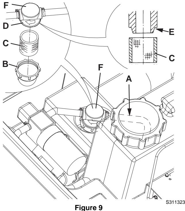
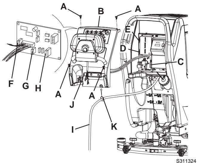
Figure 10
BRUSH/PAD-HOLDER/CYLINDRICAL BRUSH DECK DISASSEMBLY/ASSEMBLY
The machine can be equipped with either the brush/pad-holder deck (18a and 18b) or the cylindrical brush deck (18c).

NOTE
When the deck is installed/removed, it could be necessary to replace the squeegee, because they must have the same width. For correct matching of deck and squeegee, see the Squeegee Installation paragraph.
Disassembly
- Drive the machine on a level floor.
- Remove the brushes/pad-holders according to the procedure shown in the relevant paragraph. Do not remove the cylindrical brushes.
- Lower the brush/pad-holder deck by pressing the pedal (11).
- If equipped, remove the cotter pins (B, Fig. 11) and the gas spring (A).
- Disconnect the brush/pad-holder motor electrical connection (D).
- Disconnect the solution hose union (E).
- Remove the screws (C), then remove the brush/pad-holder deck (F).
Assembly
-
Assemble the components in the reverse order of disassembly, and note the following:
-
When the machine is equipped with the cylindrical brush deck (18c), the gas spring (A) must not be installed.
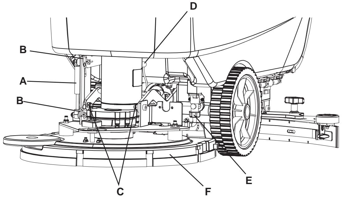
Figure 11
S311325
DETERGENT TANK CLEANING
(For machines with EDS - ECO Dosage Solution)
Clean the detergent tank (45) according to the following procedure:
- Drive the machine to the appointed disposal area.
- Open the cover (22) and check that the recovery water tank (21) is empty, otherwise empty it with the drain hose (16). Close the cover (22).
- Grasp the handle (41) and carefully lift the tank (40).
- Unscrew the plug and disconnect the hose (48) from the tank (45).
- Remove the tank by releasing it from the retainers.
- Wash the tank in the appointed disposal area.
- Install the tank (45) and connect it to the hose (48).
- When the detergent tank has been drained, the EDS - ECO Dosage Solution must be drained too (see the procedure in the following paragraph).
(For machines with EDS - ECO Dosage Solution)
- Clean the detergent tank according to the procedure shown in the previous paragraph. To remove the detergent remained in the hoses and in the pump, perform the following procedure.
- Grasp the handle (41) and carefully lower the tank (40).
- Turn on the machine by turning the ignition key (80) to "l" position.
- Turn on the EDS - ECO Dosage Solution by pressing the switch (77). Check that the switch warning light (78) turns on.
- Simultaneously press the switches (77 and 82a), until the switch warning light (78) starts flashing (after about 5 seconds).
- Release the switches and wait for the warning light (78) to stop flashing and for the vacuum system to turn on.
- Collect the detergent remained on the floor.
- Turn the ignition key (80) to "0" position.
- Grasp the handle (41) and carefully lift the tank (40), then check that the hose (48) is empty, otherwise perform the steps 3 to 9 again.

NOTE
The draining cycle lasts about 30 seconds, then the vacuum function automatically turns on, which allows to remove the solution remained.
The draining cycle can also be performed with the detergent tank (45) full of water, thus cleaning the system thoroughly.
It is advisable to perform the draining cycle when the EDS - ECO Dosage Solution is really dirty/encrusted because the machine has not been used/cleaned for a long time.
The draining cycle can be performed also to quickly fill the detergent suction hose when the tank (45) is full but the system is still empty.
If necessary, the draining cycle can be repeatedly performed.
TROUBLESHOOTING
| Trouble | Possible Cause | Remedy |
| The motors do not work; no warning light turns on. | The battery connector (12) is disconnected. | Connect. |
| The batteries are completely discharged. | Charge the batteries. | |
| The machine does not move. (Only for BA 551 D, BA 551 CD, BA 611 D) | The machine has been turned on by using the ignition key (80) and by keeping the paddle (83) pressed. | Turn the ignition key (80) to “0” position, then try to start the machine without pressing the paddle (83). |
| The brushes do not work, the red warning light (81c) is on. | The batteries are discharged. | Charge the batteries. |
| Insufficient recovery water vacuuming. | The recovery water tank (21) is full. | Empty the tank. |
| The hose (15) is disconnected from the squeezegee. | Connect. | |
| The vacuum grid (36) is clogged or the float is stuck closed. | Clean the grid or check the float. | |
| The squeezegee (25) is dirty or the squeezegee blades are worn or damaged. | Clean and check the squeezegee. | |
| The tank cover is not correctly closed, or the gasket (31) is damaged, or the compensation hole (33) is clogged. | Close the cover correctly, or replace the gasket or clean the compensation hole. | |
| Insufficient solution flow to the brushes. | The solution filter (54) or the clean water filter (51) is dirty. | Clean the filter. |
| The tank (21) is dirty (the drain hole is clogged). | Clean. | |
| Marks caused by the squeezegee. | There are debris under the squeezegee blades. | Remove the debris. |
| The squeezegee blades are worn, chipped or torn. | Replace the blades. | |
| The squeezegee has not been balanced with the handwheel (27). | Balance. |

NOTE
If the machine has an optional battery charger installed, the machine cannot operate if the charger is not on board. In case of battery charger malfunction, contact an authorised Service Center.
For further information, refer to the Service Manual, available at any Nilfisk-Advance Service Centre.
SCRAPPING
Have the machine scrapped by a qualified scraper.
Before scrapping the machine, remove and separate the following materials, which must be disposed of properly according to the Law in force:
Batteries
Brushes/pads
- Plastic hoses and components
- Electrical and electronic components (*)
(*): Refer to the nearest Nilfisk-Advance Center especially when scrapping electrical and electronic components.
INLEIDING 3
DOEL EN INHOUD VAN DEZE HANDLEIDING 3
BETREFFENDE PERSONEN 3
OPBERGEN VAN DE HANDLEIDING 3
CONFORMITEITSVERKLARING 3
IDENTIFICATIEGEGEVENS 3
ANDERE GEBRUIKERSHANDLEIDINGEN 4
VERVANGINGSONDERDELEN EN ONDERHOUD 4
MODIFICATIONS EN VERBETERINGEN 4
BEDRIJFSCAPACITEIT 4
ALGEMENE OPMERKINGEN 4
VERPAKKING VERWIJDEREN/AFLEVERING 4
VEILIGHEID 5
GEBRUIKTE SYMBOLEN 5
ALGEMENE INSTRUCTIES 5
BESCHRIJVING VAN DE MACHINE 7
OPBOUW VAN DE MACHINE 7
BEDIENINGSPANEEL 9
KLEPJE VOOR HET AFLEZEN VAN DE GEGEVENS VOOR DE ACCULADER (optionel) 9
OPBOUW VAN DE MACHINE-BESCHRIJVING 10
FUNCTIONELE BESCHRIJVING VAN DE KNOPPEN EN BEDIENGINEN 11
BESCHRIJVING VAN DE LAMPJES EN INDICATOREN OP HET BEDIENINGSPANEEL 12
BESCHRIJING VAN DE LAMPJES VOOR DE ACCU'S 12
ACCESSIONS / OPTIES 12
TECHNISCHE EIGENSCHAPPEN 13
ELEKTRISCH SCHEMA VOOR BA 551 14
ELEKTRISCH SCHEMA VOOR BA 551 D, BA 551 CD, BA 611 D 15
GEBRUK 16
CONTROLE / VOORBEREIDINGEN VOOR ACCU'S OP EEN NIEUWE MACHINE 16
DE ACCU'S MONTEREN EN HET TYPE ACCU INSTELLEN (WET OF GEL) 17
VOOR HET STARTEN VAN DE MACHINE 18
DE MACHINE STARTEN EN STOPPEN 21
MACHINE IN GEBRUIK (WASSEN/DROGEN) 22
DE TANKS LEGEN 23
NA GEBRUIK VAN DE MACHINE 24
LANGE PERIODE VAN STILLSTAND 24
EERSTE GEBRUIKSPERIODE 24
ONDERHOUD 25
ONDERHOUDSSCHEMA 25
ACCU'S OPLADEN 26
CONTROLE VAN DE BEDRIJFSUREN VAN DE MACHINE 27
REINIGING TREKKER 27
CONTROLE EN VERVANGING VAN DE RUBBERS VAN DE TREKKER 28
REINIGING VAN DE BORSTELS/PADS 29
REINIGING VAN DE TANKS, VAN HET AANZUIGROOSTER MET VLOTTER EN CONTROLRE VAN DE PAKKING VAN DE AFDEKKING 29
REINIGING VAN HET FILTER VOOR DE MOTOR VAN HET AANZUIGSYSTEEM 30
REINIGING VAN HET FILTER VAN HET REINIGINGSMIDDEL 30
REINIGING VAN HET SCHOONWATERFILTER 31
CONTROLE/VERVANGING VAN DE ZEKERINGEN 31
DEMONTAGE/MONTAGE VAN HET SCHROBDEK MET BORSTELHOUDER/PADHOUDER/HOUDER VOOR CILINDRISCHE BORSTELS 32
REINIGING VAN DE TANK MET REINIGINGSMIDDEL 33
EDS (TOEVOERSYSTEEM REINIGINGSMIDDEL) SPOELEN 33
STORINGEN LOKALISEREN 34
VERWIJDERING 34
INLEIDING

OPMERKING
-
GEVAAR!
-
LET OP!
WAARSCHUWING - ADVIES