TX-NR1000 - AV receiver ONKYO - Free user manual and instructions
Find the device manual for free TX-NR1000 ONKYO in PDF.
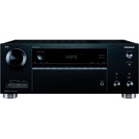
| Product type | Audio-video receiver |
| Brand | ONKYO |
| Model | TX-NR1000 |
| Channels | 7.1 |
| Output power | 130 W per channel (8 ohms, 20 Hz–20 kHz, 0.05% THD) |
| Frequency response | 5 Hz – 100 kHz (±3 dB) |
| Signal-to-noise ratio | 106 dB |
| HDMI inputs | 2 (version 1.1) |
| Component inputs | 3 |
| Composite video inputs | 5 |
| Digital audio inputs | 4 optical, 3 coaxial |
| Preamp outputs | 7.1 channels |
| Audio decoders | Dolby Digital, DTS, Dolby Pro Logic IIx |
| Network connectivity | None (non-network model) |
| Remote control | Infrared (included) |
| Dimensions (W × H × D) | 435 × 194 × 502 mm |
| Weight | 25 kg |
| Power supply | 220–240 V AC, 50/60 Hz |
| Power consumption | 750 W (max), 0.3 W (standby) |
| Maintenance and cleaning | Unplug before cleaning; use a soft dry cloth. Do not use solvents. |
| Safety | Do not expose to moisture; respect plug polarity. |
| Spare parts and repairability | Contact an authorized ONKYO service center. Parts availability depends on model. |
Frequently Asked Questions - TX-NR1000 ONKYO
User questions about TX-NR1000 ONKYO
0 question about this device. Answer the ones you know or ask your own.
Ask a new question about this device
Download the instructions for your AV receiver in PDF format for free! Find your manual TX-NR1000 - ONKYO and take your electronic device back in hand. On this page are published all the documents necessary for the use of your device. TX-NR1000 by ONKYO.
USER MANUAL TX-NR1000 ONKYO
Installation and Connections 18
Operations 48
Setup Menu 82
Using the Remote Controller 124
Thank you for purchasing an Onkyo AV Receiver. Please read this manual thoroughly before making connections and plugging in the unit.
Following the instructions in this manual will enable you to obtain optimum performance and listening enjoyment from your new AV Receiver.
Please retain this manual for future reference.
Miscellaneous 143
WARNING:
TO REDUCE THE RISK OF FIRE OR ELECTRIC SHOCK, DO NOT EXPOSE THIS APPARATUS TO RAIN OR MOISTURE.
CAUTION:
TO REDUCE THE RISK OF ELECTRIC SHOCK, DO NOT REMOVE COVER (OR BACK). NO USER-SERVICEABLE PARTS INSIDE. REFER SERVICING TO QUALIFIED SERVICE PERSONNEL.

WARNING
RISK OF ELECTRIC SHOCK DO NOT OPEN
AVIS
RISIQUE DE CHOC ELECTRIQUE NE PAS OUVIRR


The lightning flash with arrowhead symbol, within an equilateral triangle, is intended to alert the user to the presence of uninsulated "dangerous voltage" within the product's enclosure that may be of sufficient magnitude to constitute a risk of electric shock to persons.

The exclamation point within an equilateral triangle is intended to alert the user to the presence of important operating and maintenance (servicing) instructions in the literature accompanying the appliance.
Important Safety Instructions

S3125A
- Read these instructions.
- Keep these instructions.
- Heed all warnings.
- Follow all instructions.
- Do not use this apparatus near water.
- Clean only with dry cloth.
- Do not block any ventilation openings. Install in accordance with the manufacturer's instructions.
- Do not install near any heat sources such as radiators, heat registers, stoves, or other apparatus (including amplifiers) that produce heat.
- Do not defeat the safety purpose of the polarized or grounding-type plug. A polarized plug has two blades with one wider than the other. A grounding type plug has two blades and a third grounding prong. The wide blade or the third prong are provided for your safety. If the provided plug does not fit into your outlet, consult an electrician for replacement of the obsolete outlet.
- Protect the power cord from being walked on or pinched particularly at plugs, convenience receptacles, and the point where they exit from the apparatus.
- Only use attachments/accessories specified by the manufacturer.
- Use only with the cart, stand, tripod, bracket, or table specified by the manufacturer, or sold with the apparatus. When a cart is used, use caution when moving the cart/ apparatus combination to avoid injury from tip-over.
PORTABLE CART WARNING - Unplug this apparatus during lightning storms or when unused for long periods of time.
- Refer all servicing to qualified service personnel. Servicing is required when the apparatus has been damaged in any way, such as power-supply cord or plug is damaged, liquid has been spilled or objects have fallen into the apparatus, the apparatus has been exposed to rain or moisture, does not operate normally, or has been dropped.
- Damage Requiring Service
Unplug the apparatus from the wall outlet and refer servicing to qualified service personnel under the following conditions:
A. When the power-supply cord or plug is damaged,
B. If liquid has been spilled, or objects have fallen into the apparatus,
C. If the apparatus has been exposed to rain or water,
D. If the apparatus does not operate normally by following the operating instructions. Adjust only those controls that are covered by the operating instructions as an improper adjustment of other controls may result in damage and will often require extensive work by a qualified technician to restore the apparatus to its normal operation,
E. If the apparatus has been dropped or damaged in any way, and
F. When the apparatus exhibits a distinct change in performance this indicates a need for service.
16. Object and Liquid Entry
Never push objects of any kind into the apparatus through openings as they may touch dangerous voltage points or short-out parts that could result in a fire or electric shock.
The apparatus shall not be exposed to dripping or splashing and no objects filled with liquids, such as vases shall be placed on the apparatus.
Don't put candles or other burning objects on top of this unit.
17. Batteries
Always consider the environmental issues and follow local regulations when disposing of batteries.
- If you install the apparatus in a built-in installation, such as a bookcase or rack, ensure that there is adequate ventilation.
Leave 20cm (8") of free space at the top and sides and 10cm (4") at the rear. The rear edge of the shelf or board above the apparatus shall be set 10cm (4") away from the rear panel or wall, creating a flue-like gap for warm air to escape.
Precautions
1. Recording Copyright
Unless it's for personal use only, recording copyrighted material is illegal without permission of the copyright holder.
2. AC Fuse
The AC fuse inside the TX-NR1000/TX-NR5000E is not user-serviceable. If you cannot turn on the TX-NR1000/ TX-NR5000E, contact your Onkyo dealer.
3. Care
Occasionally you should dust the TX-NR1000/ TX-NR5000E all over with a soft cloth. For stubborn stains, use a soft cloth dampened with a weak solution of mild detergent and water. Dry the TX-NR1000/ TX-NR5000E immediately afterwards with a clean cloth. Don't use abrasive cloths, thinners, alcohol, or other chemical solvents, because they may damage the finish or remove the panel lettering.
4. Power
WARNING
BEFORE PLugging IN THE UNIT FOR THE FIRST TIME, READ THE FOLLOWING SECTION CAREFULLY.
AC outlet voltages vary from country to country. Make sure that the voltage in your area meets the voltage requirements printed on the TX-NR1000/TX-NR5000E's rear panel (e.g., AC 230 V, 50 Hz or AC 120 V, 60 Hz).
The Worldwide model has a voltage selector for compatibility with power systems around the world. Before you plug in this model, make sure that the voltage selector is set to the correct voltage for your area.
For USA, Canadian, and Australian models
Setting the [STANDBY/ON] switch to STANDBY does not fully shutdown the TX-NR1000/TX-NR5000E. If you do not intend to use the TX-NR1000/TX-NR5000E for an extended period, remove the power cord from the AC outlet.
For British Models
Replacement and mounting of an AC plug on the power supply cord of this unit should be performed only by qualified service personnel.
IMPORTANT
The wires in the mains lead are coloured in accordance with the following code:
Blue: Neutral
Brown: Live
As the colours of the wires in the mains lead of this apparatus may not correspond with the coloured markings identifying the terminals in your plug, proceed as follows:
The wire that is coloured blue must be connected to the terminal that is marked with the letter N or coloured black.
The wire that is coloured brown must be connected to the terminal that is marked with the letter L or coloured red.
IMPORTANT
The plug is fitted with an appropriate fuse. If the fuse needs to be replaced, the replacement fuse must be approved by ASTA or BSI to BS1362 and have the same ampere rating as that indicated on the plug. Check for the ASTA mark or the BSI mark on the body of the fuse.
IF THE FITTED MOULDED PLUG IS UNSUITABLE FOR THE SOCKET OUTLET IN YOUR HOME THEN THE FUSE SHOULD BE REMOVED AND THE PLUG CUT OFF AND DISPOSED OF SAFELY. THERE IS A DANGER OF SEVERE ELECTRICAL SHOCK IF THE CUT OFF PLUG IS INSERTED INTO ANY 13 AMPERE SOCKET.
If in any doubt, consult a qualified electrician.
For U.S. Models
Note to CATV system installer:
This reminder is provided to call the CATV system installer's attention to Section 820-40 of the NEC which provides guidelines for proper grounding and, in particular, specifies that the cable ground shall be connected to the grounding system of the building, as close to the point of cable entry as practical.
FCC Information for User
CAUTION:
User changes or modifications not expressly approved by the party responsible for compliance could void the user's authority to operate the equipment.
NOTE:
This equipment has been tested and found to comply with the limits for a Class B digital device, pursuant to Part 15 of the FCC Rules. These limits are designed to provide reasonable protection against harmful interference in a residential installation.
This equipment generates, uses, and can radiate radio frequency energy and, if not installed and used in accordance with the instructions, may cause harmful interference to radio communications. However, there is no guarantee that interference will not occur in a particular installation. If this equipment does cause harmful interference to radio or television reception, which can be determined by turning the equipment off and on, the user is encouraged to try to correct the interference by one or more of the following measures:
Reorient or relocate the receiving antenna.
- Increase the separation between the equipment and the receiver.
- Connect the equipment into an outlet on a circuit different from that to which the receiver is connected.
- Consult the dealer or an experienced radio/TV technician for help.
For Canadian Models NOTE:
THIS CLASS B DIGITAL APPARATUS COMPLIES WITH CANADIAN ICES-003.
RSS 210, Low Power Licence-Exempt Radiocommunications Devices (All FrequencyBands).
For models having a power cord with a polarized plug:
CAUTION:
TO PREVENT ELECTRIC SHOCK, MATCH WIDE BLADE OF PLUG TO WIDE SLOT, FULLY INSERT.
Important Safety Instructions 2
Precautions. 3
Features 6
Supplied Accessories. 8
Connecting the Supplied Power Cord .8
Before Using the TX-NR1000/TX-NR5000E ....9
Installing the Batteries 9
Using the Remote Controller 9
Index Parts and Facilities 10
Front Panels 10
Inner Panels 12
Rear Panel. 14
Front Panel Display 15
Remote Controller (Amp Mode) 16
Installation and Connections
Speaker Placement 18
Basic Speaker Placements for Home Theater and the Function of Respective Speakers.....18
Placing the Speakers. 19
Speaker Placement Suitable for THX Audio. 20
Speaker Placement Suitable for a Music Source such as DVD-Audio. 20
Available Speaker Placements According to the Number of Speakers 21
Connection Examples. 22
Connecting Speakers. 25
Connecting to the Speaker Terminals 25
Connecting a Subwoofer 26
Connecting Auxiliary Power Amplifier (For Speaker System [A] only) 26
Using the BTL Connection. 27
Using Bi-amp Connection. 27
Connecting Antennas 28
Connecting the Indoor FM Antenna. 28
Connecting the AM Loop Antenna. 28
Connecting an Outdoor FM Antenna. 29
Connecting an Outdoor AM Antenna.29
Connecting AV Components. 30
Types of Connection Cables and Terminals 30
Connecting Monitors such as TV or
Projector. 32
Connecting a DVD Player 33
Connecting a DVD Recorder or Digital VCR (VIDEO 1). 34
Connecting a VCR (VIDEO 2,VIDEO 3).....35
Connecting a DBS Tuner, DBS TV, or BS/CS Tuner 37
Connecting a Portable DVD Player or Video Camcorder 38
Connecting a CD Player, Turntable or Tuner 38
Connecting a Recording Device such as MD Recorder, DAT Deck, CD Recorder or Cassette Deck. 39
Connection Using the i.LINK (AUDIO) Terminal ( ). 40
Connection Using HDMI Terminals 43
Connecting Components not Reached by the Remote Controller Signals (IR IN/OUT).....45
If Remote Controller Signal Does not Reach the TX-NR1000/TX-NR5000E Remote Sensor ....45 If Remote Controller Signal Does not Reach Other Components 46
Using an External Device with 12V Trigger Terminal 46
Connecting RI-compatible AV Components 47
Connections for Remote Control (RI) 47
Operations
Basic Operation of Remote Controller Buttons 48
To Operate the TX-NR1000/TX-NR5000E (AMP Mode) 48
To Select an Input Source 48
To Operate a Connected Component (Mode Switching). 49
To Select a Source in Zone 2 or Zone 3....49
To Perform a Macro Operation 49
Customizing Your Remote Controller 49
Connecting the Power/Basic Operations.....50
Turning on the Power. 50
Operating on the TX-NR1000/TX-NR5000E.... 50
Turning on the Power from the Remote Controller. 51
Operating with Remote Controller.. 51
Using the Listening Modes 56
Selecting the Listening Mode 59
Listening to Radio Broadcasts 60
Using the Tuner 60
Tuning into a Radio Station 60
Listening to RDS Broadcasts (European models only). 62
Listening to RDS Broadcasts. 62
PTY Program Types in Europe 62
Displaying Radio Text (RT) 63
Performing a PTY Scan 63
Performing a TP Scan. 63
Enjoying Multichannel Playback 64
How to Connect 64
How to Set Up. 64
Playing Back in Multichannel Sound 65
Adjusting the Volume Level of Speakers for Multichannel Playback. 65
Enjoying Movies and Music in the Remote Zone (Zone 2/3) 66
Connecting and Setup 66
Enjoying Movies and Music in a Remote Zone 67
Recording a Source 69
Recording Audio/Video While Playing 70
Recording Audio/Video on a Component While Playing Another 70
Recording the Video from One Source and the Audio from Another Source 71
Enjoying Net Audio 72
About Net-Tune. 72
Networking Your TX-NR1000/TX-NR5000E....73
About Network Configuration 73
Using the Remote Controller. 74
Enjoying Internet Radio. 76
Playing a Music File Saved on the Net-Tune Server 78
Configuring the Music Server. 80
Setup Menu
Setup Menu. 82
OSD Map (MAIN A) 82
OSD Map (MAIN B) 84
OSD Map (ZONE 2) 85
Navigating the Setup Menu. 86
Hardware Setup. 87
Remote Control Setup Sub-menu 87
TV Format Sub-menu. 87
AM Frequency Setup Sub-menu (Asian and Australian Models Only) 87
Speaker/Output Setup 88
Speaker Configuration Sub-menu. 88
Speaker Impedance Sub-menu 89
Speaker Crossover Sub-menu. 89
Speaker Distance Sub-menu 89
Notch Filter Sub-menu 90
Level Calibration Sub-menu. 90
THX Audio Setup Sub-menu. 91
Audio Output Assign Sub-menu. 91
Video Output Assign Sub-menu 92
Input Setup 93
Audio Assign Sub-menu (when input is other than NET AUDIO) 94
MusicServer Sub-menu(When input is NET AUDIO) 95
Video Assign Sub-menu. 95
Listening Mode Preset Sub-menu. 96
Character Edit Sub-menu. 97
IntelliVolume Sub-menu 98
Delay Sub-menu 98
12V Trigger Assign Sub-menu. 98
Listening Mode Setup. 99
Mono Setup Sub-menu 99
Multiplex Setup Sub-menu 99
Stereo Setup Sub-menu. 100
Direct, Pure Audio Setup Sub-menu 101
Multichannel Input Setup Sub-menu 102
i.LINK(IEEE1394):DVD-Audio Input Setup Sub-menu 103
i.LINK(IEEE1394):SACD Input Setup Sub-menu 105
Dolby Digital Setup Sub-menu 106
DTS Setup Sub-menu 108
AAC Setup Sub-menu 109
Dolby Pro Logic IIx/DTS NEO:6 (2ch Input only)
Setup Sub-menu 110
THX Setup Sub-menu 112
Mono Movie Setup/Enhance Setup/Orchestra Setup/Unplugged Setup/Studio-Mix Setup/TV Logic Setup Sub-menu 114
All Ch Stereo Setup/Full Mono Setup Sub-menu 115
Dolby Virtual Speaker Setup Sub-menu ....116
Dolby Headphone Setup Sub-menu 117
Audio Adjust 118
Tone Control Sub-menu 118
Preferences. 119
Volume Setup Sub-menu 119
Headphone Level Setup Sub-menu 119
OSD Setup Sub-menu. 119
OSD Position Sub-menu 119
i.LINK Setup. 120
Wakeup Setup. 120
OSD for DVD 120
OSD for DVD (Zone 2) 120
DVD Output Synchro 120
Network Setup 121
IP Address Sub-menu 121
Proxy Sub-menu. 121
MAC Address Sub-menu. 121
Client Sub-menu 122
Lock/Version Setup. 123
Lock Setup Sub-menu 123
Firmware Version Sub-menu. 123
Using the Remote Controller
Operating Onkyo Products Using the Remote Controller 124
Operating Onkyo Products Using the RI Connection 124
DVD Mode 124
CD Mode 126
MiniDisc Mode 127
Tape Mode 128
Using the Remote Controller with Other Components. 129
Entering a Remote Control Code 129
Learning Commands from Another Remote Controller 136
Using Macros. 137
Other Settings for the Remote Controller...139
Editing Remote Controller Modes. 139
Resetting the Remote Controller 141
Using the Remote Controller with Radio Frequency (RC-558M only) 141
Changing the Remote Controller's Control ID. 142
Miscellaneous
Relationship Between Input Source and Listening Mode 143
Troubleshooting 146
Power 146
Audio 146
Video 147
Tuner 147
Remote Controller 147
Recording 148
Zone 2/Zone 3. 148
Net-Tune. 148
Others. 148
Error Messages 149
Specifications 150
Features
Amplifier Features
192 kHz/24-Bit DAC for All Channels
Color-Coded Heavy Duty Dual Banana Plug Compatible Transparent Speaker Posts
Color-Coded 7.1 Multi-Channel Inputs and Pre Outs
- Powered Zone 2 and Zone 3
- 5 12V DC Trigger Outputs and 3 IR Inputs/ Outputs
- Massive, Shielded Toroidal Transformer, the kind you find only in the best high end audio equipment, to provide copious amounts of pure current
- Huge Custom Designed Audio Tuned Reference Capacitors to deliver greater power at low frequencies, and provide tremendous continuous power reserves during the most dynamic sound effects and music demands
- Powerful Transistors. These high power, high quality transistors are ready to amplify your electrical signals for the highest performance possible
- High Grade Dual Aluminum Extruded Heatsinks and auto-switched cooling fan to keep things cool when the action gets hot
- WRAT (Wide Range Amplifier Technology)
- Optimum Gain Volume Circuitry
Audio/Video Features
- THX Ultra2 Certified
- THX Surround EX, DTS-ES Discrete/Matrix 6.1, DTS NEO:6, DTS 96/24, Dolby Digital EX, Dolby Pro Logic II/IIx, Dolby Headphone, Dolby Virtual Surround
- 4 Wideband Component Video Inputs and 2 Outputs
- Dual Monitor Outputs (S Video/Composite) to route the onscreen signal to a small monitor and make adjustments without distracting the audience
13 Digital Inputs (1 Optical on Front) (7 Optical/6 Coaxial/12 Assignable) to connect any variety of digital sources to the TX-NR1000/TX-NR5000E's powerful digital processor - 4 Digital Outputs (2 Optical/2 Coaxial/4 Assignable) to make direct digital dubs to other digital devices
- Wolfson 192kHz / 24 -Bit D/A Converters for all channels
- Dual 32-Bit DSP Chips for high grade main and multizone decoding
Non-Scaling Configuration
Next Generation User Interface
- HDMI (High Definition Multimedia Interface)
- i.Link (IEEE1394) Digital Input for DVD-Audio and SACD
- Net-Tune Function with MP3/WAV/WMA Decoding
- Ethernet Plug-In Capability and 1 Output
- Bi-Directional RS-232 Port to download new programs and provide easy interface with touchscreen controllers from other manufacturers
- Composite and S Video to Component Video Upconversion (NTSC and PAL Compatible)
- Speaker A and B Mode for 7.1 Channels
- BTL and Bi-Wiring Connectable for FL/FR with SBR/SBL
- Dual 32-Bit DSP Chips for high grade main and multizone decoding
- 5 12V DC Trigger Outputs and 3 IR Inputs/ Outputs for multizone operation of multiple components
- Individual Crossover Adjustment
FM/AM Tuner Features
40 FM/AM Presets
FM/AM Auto Tuning
Other Performance Features
- VLSC (Vector Linear Shaping Circuitry)
- Solid Aluminum Volume Knob for quality you can feel—ergonomically pleasing and convenient for those quick in-the-dark level changes
- Separate PC Boards to keep audio and video signals completely separate
- Rec Out Selector (On Front) to tape one program while watching or listening to another
- Gold-Plated RCA Jacks to resist corrosion and provide distortion-free signal transmission
- 2 Sets of Color-Coded Heavy Duty, Transparent, Dual-Banana-Plug Speaker Terminals for all channels to provide distortion-free signal transfer and accommodate heavy gauge speaker cable
- Impeccable Quality Materials — a heavy gauge, reinforced steel chassis, rigid aluminum panels and brazen stabilizers to enhance overall chassis stability
- Large Multi-Emitter Output Transistors to provide faster switching speed, which translates into a wider dynamic range
- Zone 2 Multiroom/Multisource (audio and video) to set up additional rooms
-
Detachable Heavy Duty IEC Power Cord to minimize interference from external sources and increase power stability—detachable for ease of installation
-
Audiophile Grade Parts
- IntelliVolume
Pure Audio Mode - Digital Upsampling
- Absolute Ground Plate
Large, Fluorescent, 35 Dot Matrix Display With 4 Mode Dimmer - For Ultimate Control—The Last Remote You'll Ever Need
- A-Form Listening Mode Memory
In catalogs and on packaging, the letter added to the end of the product name indicates the color of the TX-NR1000/TX-NR5000E. Specifications and operation are the same regardless of color.
- THX is a trademark or registered trademark of THX Ltd.
- HDMI, the HDMI logo and High Definition Multimedia Interface are trademarks or registered trademarks of HDMI Licensing, LLC.
- Manufactured under license from Dolby Laboratories. "Dolby," "Pro Logic," "Surround EX," and the double-D symbol are trademarks of Dolby Laboratories.
- "DTS," "DTS 96/24," "DTS-ES," and "NEO:6" are trademarks of Digital Theater Systems, Inc.
- The i.LINK logo is a trademark of Sony Corporation, registered in the U.S. and other countries.

- Re-Equalization and the "Re-EQ" logo are trademarks of THX Ltd.
- "Net-Tune" is a trademark of Onkyo Corporation.
- Windows Media and the Windows logo are trademarks, or

Plays Windows MediaTM
registered trademarks of Microsoft Corporation in the United States and/or other countries.
Intel and Pentium are registered trademarks of Intel Corporation.
- MPEG Layer-3 audio coding technology licensed from Fraunhofer IIS and THOMSON multimedia.
Xantech is a registered trademark of Xantech Corporation.
- Niles is a registered trademark of Niles Audio Corporation.
"This product incorporates copyright protection technology that is protected by U.S. patents and other intellectual property rights. Use of this copyright protection technology must be authorized by Macrovision Corporation, and is intended for home and other limited consumer uses only unless otherwise authorized by Macrovision. Reverse engineering or disassembly is prohibited."
THX Ultra2
Before any home theater component can be THX Ultra2 certified, it must pass a rigorous series of quality and performance tests. Only then can a product feature the THX Ultra2 logo, which is your guarantee that the Home Theater products you purchase will give you superb performance for many years to come. THX Ultra2 requirements define hundreds of parameters, including power amplifier performance, and pre-amplifier performance and operation for both digital and analog domains. THX Ultra2 receivers also feature proprietary THX technologies (e.g., THX Mode) which accurately translate film soundtracks for home theater playback.
For European Models
Declaration of Conformity
We, ONKYO EUROPE ELECTRONICS GmbH LIEGNITZERSTRASSE 6, 82194 GROEBENZELL, GERMANY

declare in own responsibility, that the ONKYO product described in this instruction manual is in compliance with the corresponding technical standards such as EN60065, EN55013, EN55020 and EN61000-3-2, -3-3.
GROEBENZELL, GERMANY

ONKYO EUROPE ELECTRONICS GmbH
Supplied Accessories
Make sure you have the following accessories:

Remote Controller & Three Batteries (AA/R6)
AM Loop Antenna (not supplied with USA and Canadian models)
Indoor FM antenna (not supplied with USA and Canadian models)

connector type varies from country to country
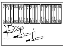
Speaker Labels
Terminal Wrench

A wrench to screw/unscrew the speaker terminal cap.
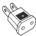
Power Plug adapter
Only supplied in certain countries. Use this adapter if your AC outlet does not match the plug on the TX-NR1000/TX-NR5000E's power cord (adapter varies from country to country).

Power Cord
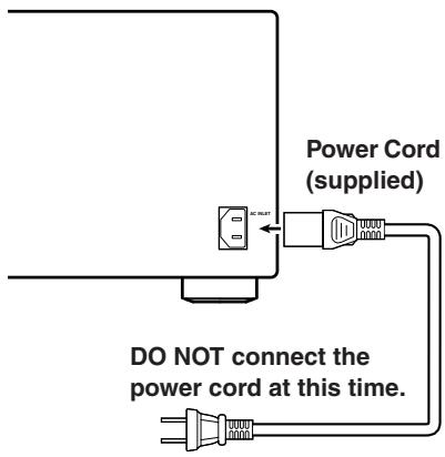
Connecting the Supplied Power Cord
Plug the supplied power cord into this AC INLET.
- Do not use a power cord other than the one supplied with the TX-NR1000/TX-NR5000E. The power cord supplied is designed for use with the TX-NR1000/ TX-NR5000E and should not be used with any other device.
- Never have the power cord disconnected from the TX-NR1000/TX-NR5000E while the other end is plugged into the wall outlet. Doing so may cause an electric shock. Always connect by plugging into the wall outlet last and disconnect by unplugging from the wall outlet first.
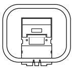
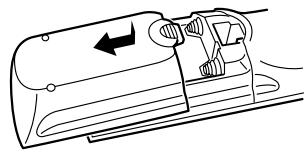
Installing the Batteries
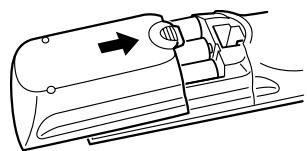
1 To open the battery compartment, press the small hollow and slide off the cover.
2 Insert the three supplied batteries (AA/R6) in accordance with the polarity diagram inside the battery compartment.
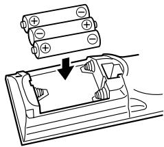
3 Put the cover onto the remote controller and slide it shut.
Notes:
- The supplied batteries should last for about six months, although this will vary with usage.
- If the remote controller doesn't work reliably, try replacing the batteries.
- Don't mix new and old batteries, or different types of batteries.
- If you intend not to use the remote controller for a long time, remove the batteries to prevent possible leakage and corrosion.
- Expired batteries should be removed as soon as possible to prevent damage from leakage or corrosion.
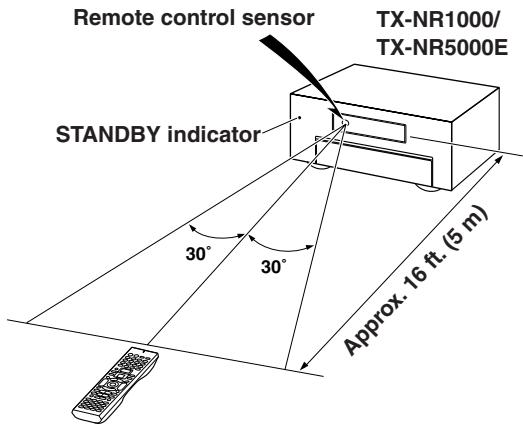
Using the Remote Controller
To use the remote controller, point it at the TX-NR1000/TX-NR5000E's remote control sensor, as shown below. The TX-NR1000/TX-NR5000E's [STANDBY] indicator flashes while a signal is being received from the remote controller.
Notes:
- The remote controller may not work reliably if the TX-NR1000/TX-NR5000E is subjected to bright light, such as direct sunlight or inverter-type fluorescent lights. Keep this in mind when installing the TX-NR1000/TX-NR5000E.
- If another remote controller of the same type is used in the same room, or the TX-NR1000/TX-NR5000E is installed close to equipment that uses infrared rays, the remote controller may not work reliably.
- Don't put anything, such as a book, on the remote controller, because the buttons may be pressed inadvertently, thereby draining the batteries.
- The remote controller may not work reliably if the TX-NR1000/TX-NR5000E is installed in a rack behind colored glass doors. Keep this in mind when installing the TX-NR1000/TX-NR5000E.
- The remote controller will not work if there's an obstacle between it and the TX-NR1000/ TX-NR5000E's remote control sensor.
- (RC-558M only) You can set the transmission signal format to infrared (IR), or radio frequency (RF) for use with the optional RF Receiver. This is useful when, for example, the TX-NR1000/TX-NR5000E is installed in a rack or is not in line of sight of the remote controller.
- To select AMP mode, press the scroll wheel. "AMP" appears on the display.
Index Parts and Facilities
Here is an explanation of the controls and displays on the front panel of the TX-NR1000/TX-NR5000E. The specifications for your model may differ due to regional requirements.
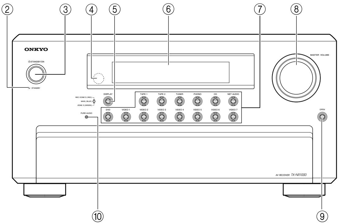
Front Panels
USA, Canadian, and Australian models
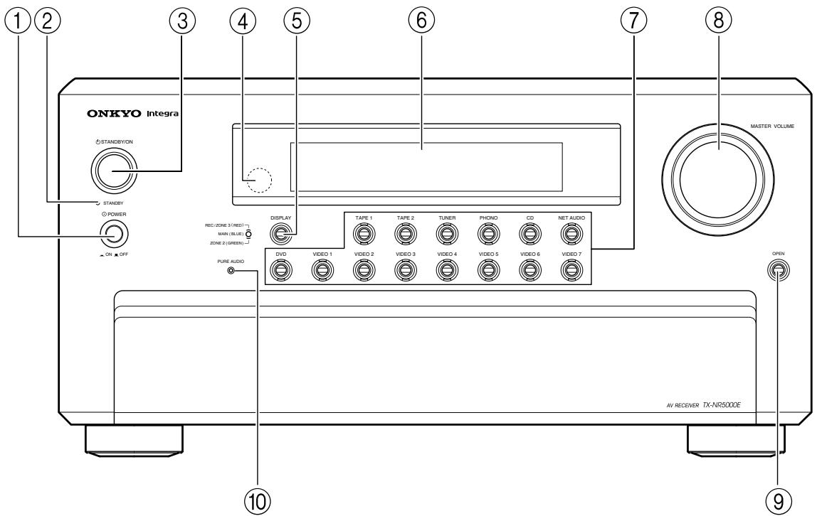
European models
For further operational instructions, see the pages indicated in brackets [ ].
① POWER switch (for all models other than USA, Canadian, and Australian models) [50]
Press to turn on and off the main power supply for the TX-NR1000/TX-NR5000E. When the TX-NR1000/TX-NR5000E is turned on with the [POWER] switch, the [STANDBY] indicator lights.
- Before turning on the power, check to make sure that all cords are properly connected.
- When the power is turned on, a sudden surge of current will occur that may adversely affect the operation of other devices. To prevent this, do not plug the TX-NR1000/TX-NR5000E into the same circuit used by sensitive equipment, e.g., computers.
② STANDBY indicator [9, 50]
Lights when the TX-NR1000/TX-NR5000E is in the standby state and when a signal is received from the remote controller.
③ STANDBY/ON button [50]
If pressed with the [POWER] switch turned on (with the receiver plugged in for USA, Canadian, and Australian models), the TX-NR1000/TX-NR5000E turns on and the display lights up. If pressed again, the TX-NR1000/TX-NR5000E returns to the standby state. In the standby state, the display is turned off and the TX-NR1000/TX-NR5000E cannot be operated.
Remote control sensor [9]
⑤ DISPLAY button [54]
Press to display information about the current input source signal. Each time you press the [DISPLAY] button, the screen changes to show you different information concerning the input signal.
⑥ Front display
⑦ Input source buttons and indicators (DVD,VIDEO 1-7, TAPE 1-2, TUNER, PHONO, CD, and NET AUDIO) [50, 60, 63, 76]
Press these buttons to select the input source for the main zone.
After selecting the input source, the corresponding indicator turns blue. If you select Zone 2, the indicator turns green. If you select Zone 3 or Rec, the indicator turns red.
⑧ MASTER VOLUME dial [50]
Use to control the volume in the main zone. The volume for the remote zone (Zone 2 and Zone 3) is independent.
⑨ OPEN button
Press this button to open the front panel door.
10 PURE AUDIO indicator [59]
Lights during pure audio playback.
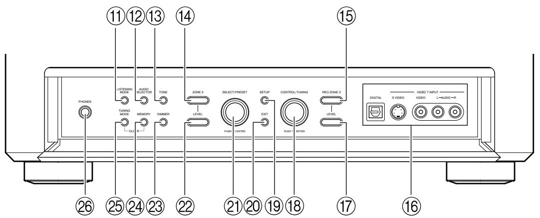
Inner Panels
USA, Canadian, and Australian models

European models
⑪ LISTENING MODE button [59]
Press this button to enter the setup mode for the listening mode. Turning the [SELECT/PRESET] allows you to select the listening mode. To confirm your selection and exit the setup mode, press the [SELECT/PRESET].
⑫ AUDIO SELECTOR button [55]
Press this button to enter the audio selector mode. Turning the [SELECT/PRESET] allows you to select the audio mode.
TONE button [52]
Press this button to enter the tone adjustment mode. Turning the [SELECT/PRESET] allows you to select the channel to adjust the tone. To adjust the tone level, turn the [CONTROL/TUNING].
14 ZONE 2 button [68]
Press this button to enter the Zone 2 configuration mode. Turning the [SELECT/PRESET] allows you to select the input source for Zone 2. Also, if you want to configure other Zone 2 settings such as standby/on setting, listening mode, volume adjustment, audio selector mode, and display settings, press this button first.
15 REC/ZONE 3 button [68, 70]
Press this button to enter the Rec/Zone 3 mode. Turning the [CONTROL/TUNING] allows you to select the input source for the Rec mode or Zone 3. Also, if you want to configure the setting for Zone 3 including standby/on setting or volume adjustment, press this button first.
Note:
Recording and Zone 3 operations uses the same circuit and therefore cannot be used at the same time.
16VIDEO7INPUTterminals
For connecting a video camera or game device.
⑰ ZONE 3 LEVEL button [68]
Press this button to enter the volume adjustment mode for Zone 3. Turning the [SELECT/PRESET] allows you to adjust the volume.
18 CONTROL/TUNING dial [52, 60, 68, 70, 86]
When the input source is FM or AM, turning this jog dial allows you to select the frequency to receive. When used with other buttons, this [CONTROL/TUNING] dial is used to select the mode settings or values. Also the dial is pressed to confirm the settings or values you select.
⑲ SETUP button [86]
Press this button to enter the setup mode. First, select the parameter to change by turning the [SELECT/PRESET] and press the [SELECT/ PRESET] to confirm the parameter. Then, change the parameter value by turning the [CONTROL/TUNING] and press the [CONTROL/TUNING] to confirm the value.
② EXIT button [86]
Press this button to return to the last menu. To exit from the setup mode, press the [SETUP] button again.
② SELECT/PRESET dial [59, 61, 63, 68, 71, 86]
When the input source is FM or AM, turning this jog dial allows you to switch between your preset stations. When used with other buttons, the [SELECT/PRESET] dial is used to select the mode settings or parameters. Also the dial is pressed to confirm the settings or parameters you select.
ZONE 2 LEVEL button [68]
Pressing this button enters the volume adjustment mode for Zone 2. To adjust volume, turn the [SELECT/PRESET].
DIMMER button (Other than European models) [52]
Press to set the brightness of the front display. There are four settings available: normal, dark, very dark, and volume only.
For European models, this function can be operated only with the remote controller.
23 RT/PTY/TP button (European models only) [63]
This button is only available on European models. Press this button to tune into the Radio Data System (RDS) for FM broadcasting. RDS was developed within the European Broadcasting Union (EBU) and is available in most European countries. Each time the button is pressed, the display changes from RT (radio text) to PTY (program type) to TP (traffic program) and then back to RT again.
24 MEMORY button [61]
Press to assign the radio station, to which you are currently tuned, as a preset channel or press to delete a previously preset station.
25 TUNING MODE button [60, 61]
This button is used to select the Auto or Manual Tuning Mode.
26 PHONES jack [52]
This is a standard stereo jack for connecting stereo headphones.
Rear Panel
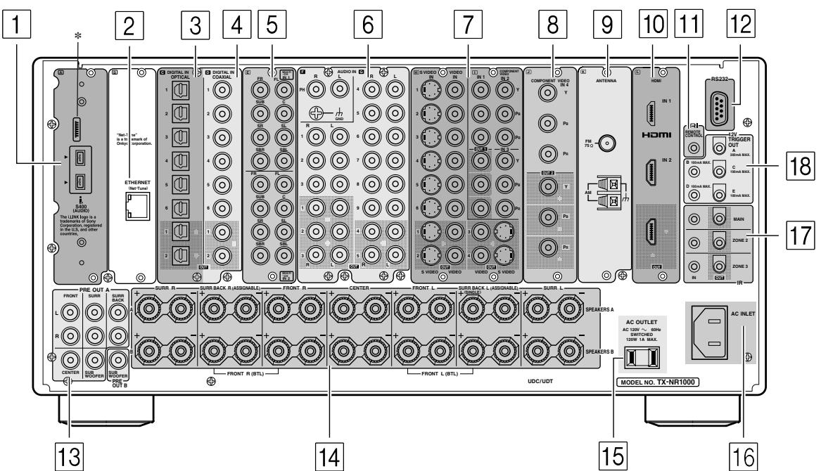
*This terminal is provided for future service enhancement and is not used currently. Never plug the cable connector for other terminals into this terminal.
1 (i) i.LINK S400 (AUDIO) terminals
Some of the Asian models are not equipped with the i.LINK(AUDIO) terminals.
These connectors are for connecting to the i.LINK (AUDIO)-ready device using a 4-pin (S400) i.LINK (AUDIO) cable. The TX-NR1000/TX-NR5000E complies with the standards on audio only transmissions.
This connector is for connecting to an Ethernet network.
3 DIGITAL OPTICAL IN/OUT
The input/output terminals for digital sound signal. The sound quality equals the signal passed through the COAXIAL terminals.
4 DIGITAL COAXIAL IN/OUT
The input/output terminals for digital sound signal. The sound quality equals the signal passed through the OPTICAL terminals.
5 MULTI-CH IN 1/2
This connector is for connecting components with a multichannel output.
Two sets of multichannel input terminals are available on the TX-NR1000/TX-NR5000E.
6 AUDIO IN/OUT
These connectors are for connecting to the audio input and output jacks on audio/video components. To connect a turntable, connect to the PH jacks. In addition to the PH jacks, the TX-NR1000/ TX-NR5000E offers nine input and five output jacks.
VIDEO/SVIDEO IN/OUT
These connectors are for connecting to the video input and output jacks on video components. Six input and 4 output jacks are available for each of VIDEO and SVIDEO connection.
8 COMPONENTVIDEOIN/OUT
These connectors are for connecting to the component video outputs/inputs of video components that have them. European and Asian models are equipped with three inputs and one output for the RCA-type COMPONENT connection and one input and output for the BNC-type COMPONENT connection.
For other than European and Asian models, there are four inputs and two outputs for the RCA-type COMPONENT connection.
Check the type of terminals or jacks on the device to connect before making connections.
9 ANTENNA (FM/AM)
These jacks are for connecting the FM indoor antenna and the AM loop antenna that are supplied with the TX-NR1000/TX-NR5000E.
10 HDMI IN/OUT
This interface can transfer digital audio and video signals simultaneously. The terminal can be connected to the HDMI terminal on the components such as DVD player, set top box (B tuner), projector, and digital TV.
11 RIREMOTECONTROL
This jack is for connecting other Onkyo components equipped with the same Rl terminal. The audio connection cables must also be connected.
12 RS 232
This port is for connecting the TX-NR1000/ TX-NR5000E to home automation and external controllers.
PRE OUT A/B
To use the TX-NR1000/TX-NR5000E as a preamplifier, connect a power amplifier to this jack.
14 SPEAKERS A/B
These terminals are for connecting the speakers. Two sets of home theater connections are available (simultaneous playback of different sources in each of two home theaters is not supported). Depending on your system, various speaker connections will be available. For example, you can use the surround back speakers for playback in a different room.
15 AC OUTLET
The TX-NR1000/TX-NR5000E is equipped with AC mains outlets for connecting the power cords from other devices so that their power is supplied through the TX-NR1000/TX-NR5000E. By doing this, you can leave the connected device turned on and have the [STANDBY/ON] button on the TX-NR1000/TX-NR5000E turn on and off the
device together with the TX-NR1000/ TX-NR5000E.
The shape, number, and total capacity of the AC outlets may differ depending on the area of purchase.
Caution:
Make sure that the total capacity of the components connected to the TX-NR1000/TX-NR5000E does not exceed the capacity that is printed on the rear panel (e.g., AC 120V - 60Hz SWITCHED 120W 1A MAX.).
16 AC INLET
This connector is for connecting the supplied power cord.
17 IR IN/OUT
These connectors are for connecting the remote sensor of a multiroom kit (sold separately). The connectors are provided for main room, Zone 2, and Zone 3.
18 12V TRIGGER OUT
These connectors are used to connect to the 12V TRIGGER IN terminal of a component. Available connectors are one with maximum current capacity of 200mA and four with 100mA .
Front Panel Display
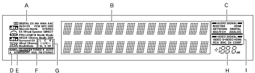
A Listening mode or input format indicators
One of these indicators lights to show the format of the current input source. In addition, one of the listening mode indicators lights to indicate the current listening mode.
B Multifunction display
During normal operation, shows the current input source. When the FM or AM input is selected, shows the frequency and preset number. When the [DISPLAY] button is pressed, shows the listening mode and input source format.
C Audio input signal path indicators
Shows from which terminal the audio input signal is coming.
D MAIN A/B indicators
Indicates which room is currently in use.
E SLEEP indicator
Lights when the sleep timer is turned on.
F Tuning indicators
AUTOindicator
Lights when receiving FM broadcasts in the stereo mode. Turns off when placed into the monaural mode.
RDS indicator (European models only)
Lights when an RDS station is being received.
TUNED indicator
Lights when a radio station is being received. MEMORY indicator
Lights when the [MEMORY] button is pressed to preset a radio station.
FM STEREO indicator
Lights when an FM broadcast station is being received in stereo. Turns off when placed into the monaural mode.
G Program format display
When the input source is DVD video, Super Audio CD, or compressed digital audio signal such as Dolby Digital and DTS, the channels corresponding to the input source light.
H Volume display
Shows the volume level.
Video input signal path indicators
Shows from which terminal the video input signal is coming.
Remote Controller (Amp Mode)
The TX-NR1000/TX-NR5000E's remote controller is a multipurpose device that can be used to control not just the TX-NR1000/TX-NR5000E but your other AV components as well. This section explains how its various operating modes can be used to control the TX-NR1000/TX-NR5000E. When you use the Net-Tune mode, see page 74 for details. See page 124-136 for information on using the remote controller to control Onkyo components connected via RI and TVs, VCRs, and AV components made by other manufacturers.
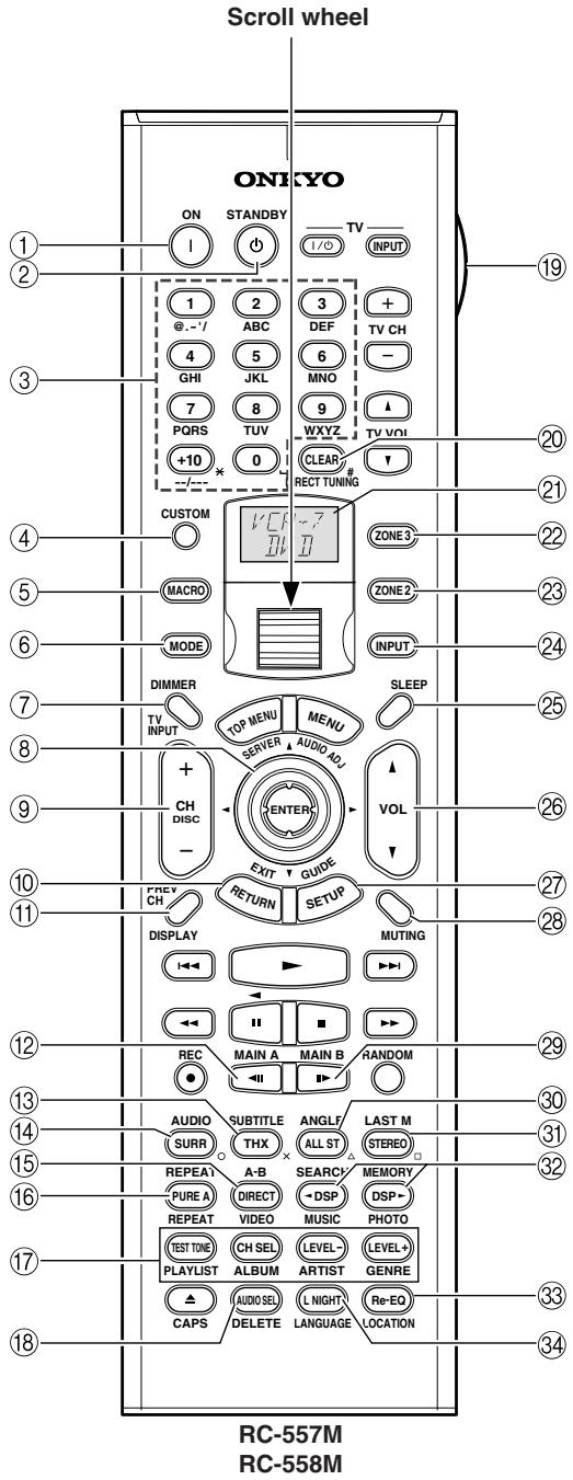
Amp mode is used to control the TX-NR1000/ TX-NR5000E. To select Amp mode, press the scroll wheel. "AMP" appears on the display.
Note:
While neither the [INPUT] button nor the [MODE] button is illuminated, rolling the scroll wheel changes the input source and remote controller mode simultaneously.
① ON button
This button is used to turn on the TX-NR1000/ TX-NR5000E.
(2) STANDBY button
This button is used to set the TX-NR1000/ TX-NR5000E to Standby.
③ Number/letter buttons
These buttons are used to enter numbers and letters.
④ CUSTOM button
This button is used to access various settings that you can use to customize the operation of the remote controller.
⑤ MACRO button
This button is used with the Macro function.
⑥ MODE button
This button is used with the scroll wheel to select the remote controller modes.
⑦ DIMMER button
This button is used to adjust the display brightness.
Up/Down/Left/Right [▲]/[▼]/[▲] /[▶] & ENTER buttons
These buttons are used to select items on the onscreen setup menus (OSD). The [ENTER] button is also used to enter names and to confirm settings.
CH +/- button
This button is used to select radio presets.
RETURN button
This button is used to return to the previously displayed onscreen setup menu (OSD).
⑪ DISPLAY button
This button is used to display various information about the currently selected input source.
12 MAIN A button
For the speakers used in main room A, every press of this button toggles the status between enabled and disabled.
⑬ THX button
This button is used to select the THX listening modes.
14 SURR button
This button is used to select the Dolby and DTS listening modes.
15 DIRECT button
This button is used to select the Direct listening mode.
16 PURE A button
This button is used to select the Pure Audio listening mode.
TEST TONE, CH SEL, LEVEL- & LEVEL+ buttons
These buttons are used to adjust the level of each speaker individually. These functions can be set only with the remote controller. The [LEVEL-] and [LEVEL+] buttons are also used to adjust the volume in Zone 2 or Zone 3.
18 AUDIO SEL button
This button is used to select the audio input signal format: analog, digital, multichannel, or i.LINK.
19 LIGHT button
This button is used to turn on or off the remote controller's illuminated buttons.
20 DIRECT TUNING button
This button is used with the number buttons to select a radio station by entering its frequency. Press this button first, and then use the number buttons to enter the frequency.
② Display
The top line of this LCD display shows the name of the currently selected input source. The bottom line shows the currently selected remote controller mode.
ZONE3button
This button is used when you want to set the volume and input source for Zone 3.
ZONE2button
This button is used when you want to set the volume and input source for Zone 2.
24 INPUT button
This button is used to select the input source. Press this button first, and then roll the scroll wheel until the name of the input source appears on the display.
25 SLEEP button
This button is used to set the Sleep function. This function can be set only with the remote controller.
VOL 1/1 button
This button is used to set the volume of the TX-NR1000/TX-NR5000E.
27 SETUP button
This button is used to access the onscreen setup menus (OSD) that appear on the TV.
28 MUTING button
This button is used to mute the TX-NR1000/ TX-NR5000E. This function can be set only with the remote controller.
29 MAIN B button
For the speakers used in main room B, every press of this button toggles the status between enabled and disabled.
30 All ST button
This button is used to select the All Ch Stereo listening mode.
③ STEREO button
This button is used to select the Stereo listening mode.
DSP/DSP buttons
These buttons are used to select the listening modes.
33 Re-EQ button
This button is used to turn on and off the Re-EQ function.
34 L NIGHT button
This button is used to set the Late Night function.
Speaker Placement
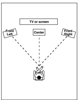
Basic Speaker Placements for Home Theater and the Function of Respective Speakers
The TX-NR1000/TX-NR5000E has many excellent features to recreate a clear three-dimensional sound image and lively sound movement. This enables you to enjoy, at home, the rich sound effects of a live theater or concert hall performance. When playing a DVD, you can enjoy sound effects provided by DTS or Dolby Digital, depending on recording format. In addition, you can enjoy THX sound and Onkyo's proprietary DSP surround playback for TV or digital satellite broadcasts.
Front left and right speakers
Outputs overall sound. They play the most important role in a home theater system, by creating basic sound images and fields.
Center speaker
Complements the sound effects from front left and right speakers to enrich and clear the sound image and movement. In movies, an actor's speech comes mainly from the center speaker.
Subwoofer
Outputs only bass sounds to enhance and complement bass sound effects.
Surround back speakers
Enhances the sound space representation with surround channel signals. Recreating sound movement effects and sound fields behind the listener gives a more realistic experience.
Surround left and right speakers
Enhances the sensation of being at a live performance by giving three-dimensional sound movement to the sound effects.
- For optimum surround playback, set the distance between the listener and the speakers so that the time it takes the sound to reach the listener is same. Also, you need to set each speaker volume level individually in order to balance the volume level between speakers (See pages 88 and 90).
Placing the Speakers
To fully enjoy surround sound, the configuration and placement of the speakers used are important. Be sure to read through the descriptions in the previous page and shown below.
This section provides the examples and descriptions that assume a typical situation.
Front Left and Right Speakers, and Center Speaker
- Place the front left and right speakers symmetrically and so that the distance from the listening position is the same.
- When placing speakers, direct the speakers toward the position of the listener's ears where the listener sits to enjoy music or movies.
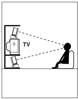
- Place the three speakers so that the heights of the three speakers are aligned. The ideal height for the speakers is the height of the listener's ears. When placing the center speaker above or below the TV, tilt it toward the listener's ears.
- Place the center speaker as close to the screen or monitor as possible and in the center between the left and right front speakers. When placing the center speaker near the TV, use
- If no center speaker is used, place the left and right front speakers closer to each other.
Left and Right Surround Speakers
- Place these speakers on each side of, or angled behind, the listener.
- Place the surround speakers symmetrically from the listener position and so that the distance from the listener is equal between left and right surround speakers.
- When enjoying mainly movies, placing the surround speakers about 3 feet (1 m) higher than the height of the listener's ears, results in more of a surround effect.
- When enjoying mainly music, placing the surround speakers at the height of the front speakers may provide a better surround effect.
- When using surround back speakers in addition to the surround speakers, placing the surround speakers slightly forward from their current position will make the sound movement smoother.
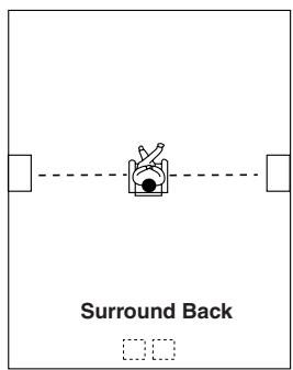
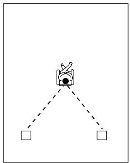
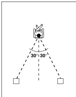
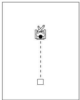
Surround Back Speakers
- Place the speakers about 3 feet (1 m) or higher than the height of the listener's ears.
- When using one surround back speaker, place it behind the listener.
- When using two surround back speakers, place them behind the listener so that the angles between the lines from each surround back speaker to the listener and a line straight back from the listener are about 30 degrees, forming an equilateral triangle of the listener and the two surround back speakers.
*When using a THX-certified speaker system, also refer to "Speaker Placement Suitable for THX Audio" on the next page.
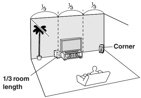
Subwoofer
Using a subwoofer greatly improves the volume level and sound quality of bass sounds. The subwoofer effect depends not only on the listening position but also on the shape of the listening room.
- In general, place the subwoofer in a corner of the room or at a point 1/3 the width of the room.
- Play a movie or music that contains high quality bass sounds to determine the subwoofer placement. Change the subwoofer's position and check the effect, then select the position where the bass sounds are best heard.
- You can place two subwoofoers for more powerful and richer heavy bass sounds.
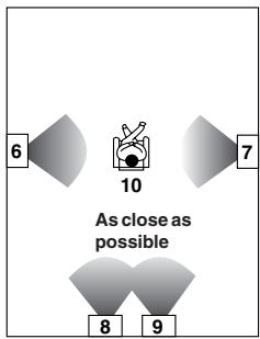
Speaker Placement Suitable for THX Audio
To enjoy sources using the THX Cinema or THX Surround EX technology, we recommend using a THX speaker system from THX Ltd. A speaker system supporting the THX Ultra2 standard is best suited for THX Ultra2 Cinema or THX Music Mode.
The layout example on the right represents a case using the dipole speakers. A dipole speaker is a two-way directivity speaker that outputs the same sound in two directions such as forward and backward.
Most dipole speakers are marked with an arrow indicating how they should be oriented in the room in order to match their phases*. Dipole surround speakers should be placed so that their arrows point forward toward the screen, and dipole surround back speakers should be placed so that their arrows point toward each other.
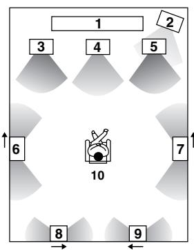
Layout with dipole speakers
1 TV or screen
2 Subwoofer
3 Front left speaker
4 Center speaker
5 Front right speaker
6 Surround left speaker
7 Surround right speaker
8 Surround back left speaker
9 Surround back right speaker
10 Listening position
*Phase: The word represents the waveform position in one cycle (0 to 360 degrees) of a sine wave. If the phase does not match between multiple waveforms due to the distance between multiple speakers, the speaker orientation, or the miswiring of positive and negative poles, the sound image or space may be obscured or the sound may be less easy to listened to.
When playing the source in the THX Ultra2 Cinema or THX Music Mode format using two surround back speakers supporting the THX Ultra2 standard, place them as close together as possible. After placing the surround back speakers, perform the settings described in the "THX Audio Setup" (page 91).
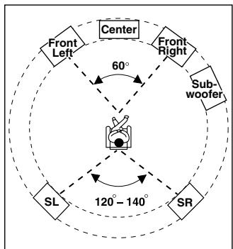
Speaker Placement Suitable for a Music Source such as DVD-Audio
This placement is based on the ITU-R* recommendation. In this placement, five speakers with the same performance capabilities are used for front left and right, center, and left and right surround speakers, and they are placed so that the distances between every speaker and the listening position are equal to each other and the heights of the speaker and the listener's ears are in the same. A mixing studio used for making multichannel DVD-Audio source material adopts this placement.
*ITU-R: International Telecommunication Union Radiocommunication Sector
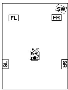
Available Speaker Placements According to the Number of Speakers
The following speaker placements will be available according to the number of speakers connected to the TX-NR1000/TX-NR5000E. For the number of speaker channel, .1 ch represents a subwoofer.
Key to abbreviations:
FL: Front left speaker, FR: Front right speaker, C: Center speaker, SL: Surround left speaker, SR: Surround right speaker, SBL: Surround back left speaker, SBR: Surround back right speaker, SW: Subwoofer
2 ch/2.1 ch
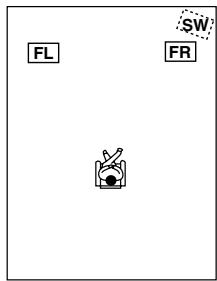
This placement is used with two speakers (front left and right speakers). It is optimum for 2 ch sources including analog 2 ch, 2 ch linear PCM, Dolby Digital, DTS, DTS96/24, and AAC format sources. When the number of channels in the source is 3.1 or greater, the signals will be distributed
through the left and right channels accordingly.
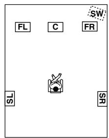
3 ch/3.1 ch
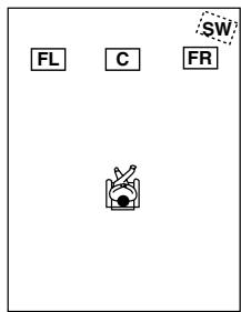
This placement is used with three speakers (front left, front right, and center speakers). When the number of channels in the source is 4.1 or greater, the signal for surround and surround back channels will be output through the front left and right speakers.
4 ch/4.1 ch
In this placement, when the number of channels in the source is 5.1 or greater, the center channel signal will be output through the front left and right speakers, and the surround back channels will be output through the surround speakers.
5 ch/5.1 ch
This placement is suitable for playing 5.1 ch sources including analog multichannel, Dolby Digital, DTS, and AAC format sources. When the source is 2 ch or mono, the signal will be decoded with Dolby Pro Logic II or DTS NEO:6 format and played as 5.1 ch sources.
When the number of channels in the source is 6.1 or greater, the surround back signal will be distributed through the surround left and right speakers accordingly.
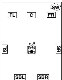
6 ch/6.1 ch/7 ch/7.1 ch (with center speaker)
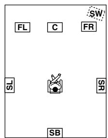
This placement is suitable for playing 6.1 ch sources including DTS-ES Matrix/ Discrete and Dolby Surround EX format signals.
When you use two surround back speakers, the same signal will be output from them because the surround back channel is mono. When the source is 2 ch or mono, it will be decoded with the Dolby Pro Logic IIx/DTS NEO:6 format and played as 6.1/7.1 ch sources.
6 ch/6.1 ch/5 ch/5.1 ch (without center speaker)
This placement is suitable for playing 5.1 or 6.1 ch sources when the surround back sound is much more preferred than the center sound with less speaker units than the normal configuration. The center channel signal will be output through the front left and right speakers.
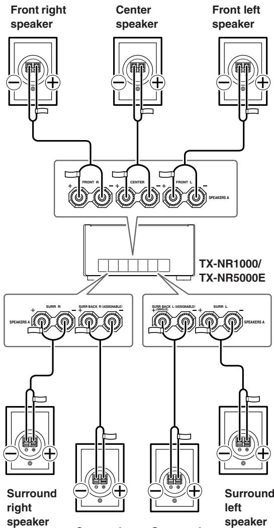
Connection Examples
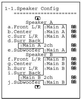
The TX-NR1000/TX-NR5000E has two speaker terminal blocks for speaker system [A] and [B]. This allows you to build two 7.1 ch home theater systems, and various speaker placements and connections are also available. For example, some channels of either speaker system can be used for another room (Zone 2), or you can select one of two speaker systems for playback according to the source.
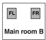
When you use two speaker systems, you have to associate the speakers with the zone (e.g., Main A, Main B, etc.). After making the association, for example, pressing the "MAIN A" button on the remote controller will output the source from the speakers configured as "Main A."
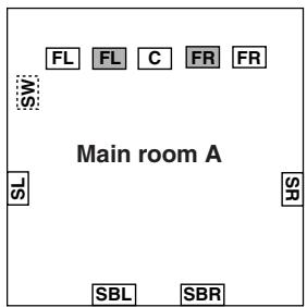
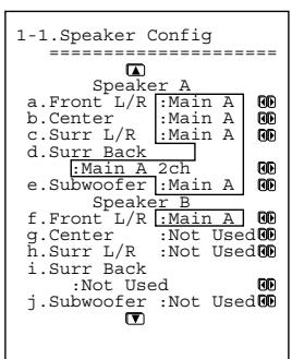
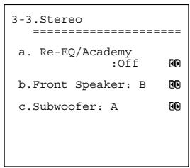
Here are some examples of speaker placement and zone association. These examples can be your reference when you build your own home theater system. The illustration on the right represents the actual settings displayed corresponding to each example. For details on configuring speaker placement and zone association, see page 88.
*In the following illustrations, white speakers denote speaker system [A] and gray ones denote speaker system [B].
*Key to abbreviations:
FL: Front left speaker; FR: Front right speaker; C: Center speaker; SL: Surround left speaker; SR: Surround right speaker; SBL: Surround back left speaker; SBR: Surround back right speaker; SW: Subwoofer
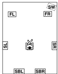
When you wish to configure 7.1 ch speaker system in the main room A only, the initial setting can be used without any modification.
Main room A: 7.1 ch speaker system; Main room B: 7.1ch speaker system
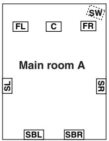
- Set all the zone parameters for speaker system [A] to "Main A."
- Set all the zone parameters for speaker system [B] to "Main B."
- Pressing the [MAIN A] or [MAIN B] button causes the sound to be output from the speaker system associated with the zone button. Both speaker systems cannot be selected simultaneously.
- If you set all the zone parameters for speaker system [B] to "Main A" and play a single source, the same audio signal will be output from both speaker systems [A] and [B].
Main room A: 7.1 ch speaker system; Main room B: 5.1 ch speaker system; Sub room (Zone 2): 2 ch speakers
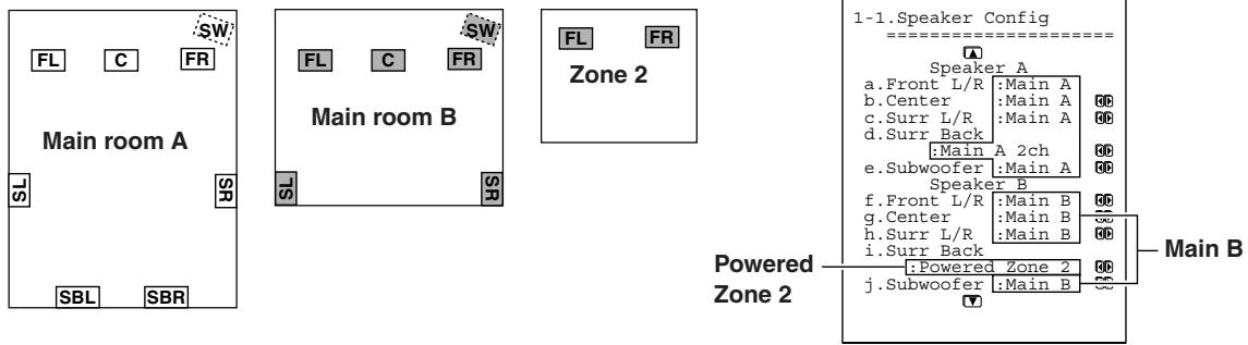
- Set all the zone parameters for speaker system [A] to "Main A." Set the zone parameters for speaker system [B] to "Main B" and "Zone 2" accordingly.
- Both main room A and B cannot be used simultaneously. However, while either of the main rooms is used, you can enjoy a different source in Zone 2.
- Note that when you use Zone 2, the surround back speakers for main room A cannot be used since Zone 2 uses the surround back speaker circuit for main room A.
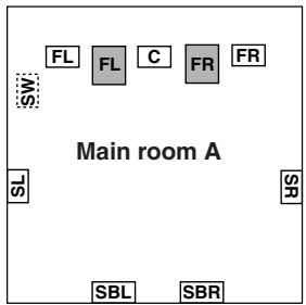
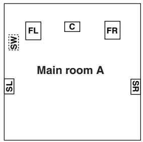
Main room A: 7.1 ch speaker systems and the two additional front speakers
(When you want to use speaker system [A] for movies and enjoy 7.1 surround sound and the two additional front speakers for classic music.)

Here is an example of the stereo sources.
- Set all the zone parameters for speaker system [A] to "Main A."
- Set the front speaker parameters for speaker system [B] to "Main A."
- If you want to use the front speakers of speaker system [B] for specific sources, select the source and set the front speaker setting parameters to "B" in the listening mode setup menu.
When you want to output to both speaker systems simultaneously, you can choose the "A+B" setting unless any of the speakers has an impedance of 8 ohm or lower.
- To output the sound, press the [MAIN A] button on the remote controller.
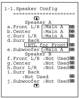
Main room A: 7.1 ch speaker system and the two additional front speakers connected through the BTL or bi-amp connection (when you want to use either the 7.1 ch speakers or the additional front speakers according to the source)
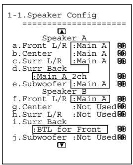
Here is an example of the stereo sources.
- Set all the zone parameters for speaker system [A] to "Main A."
- For speaker system [B], set the front speaker parameters to "Main A" and the surround back speaker parameters to "BTL for Front" or "Bi-Amp for Front" (For details on connections, see page 27).
- When you want to use the front speakers of speaker system [B] for specific sources, select the source and set the front speaker parameters to "B" in the listening mode setup menu.
*When using the BTL or bi-amp connections, the two speaker systems cannot be used to output simultaneously due to the speaker impedance limitation.
Main room A: 5.1 ch speaker system including the front speakers connected through the BTL or bi-amp connections
- For speaker system [A], set the surround back speaker parameters to "BTL for Front" or "Bi-Amp for Front" and all the other speaker parameters to "Main A" (For details on speaker connections, see page 27).
- For speaker system [B], set the speaker parameters to "Not Used."
*When using the BTL or bi-amp connections, you cannot use Zone 2 since the surround back channel is used for the front speakers of main room A.
Main room A: 7.1 ch from the speaker system [A] and additional subwoofer and surround speakers from speaker system [B] (suitable for enjoying more powerful and lively surround sound in main room A); Main room B: two front speakers from speaker system [B] using the BTL or bi-amp connections
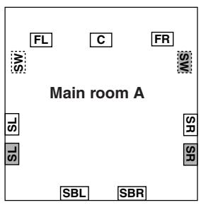
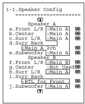
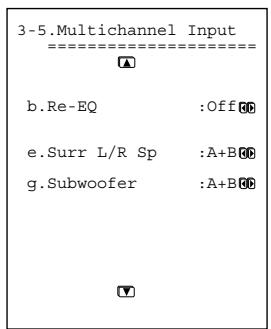
Here is an example of the multichannel sources.
- For speaker system [A], set all the speaker parameters to "Main A."
- For speaker system [B], set the surround speaker and subwoofer parameters to "Main A," the front speaker parameters to "Main B," and the surround back speaker parameters to "BTL for Front" or "Bi-Amp for Front" (For details on speaker connection, see page 27).
- When you want to use the surround speakers and subwoofer of speaker system [B] for specific sources, select the source and set the parameters for these speakers to "B" or "A+B" in the listening mode setup menu.
When you set the parameter to "B," the audio signal comes out from the surround speakers and subwoofer of speaker system [B]. When you set the parameter to "A+B," the signal comes out from the surround speakers and subwoofer of both speaker systems [A] and [B].
Connecting Speakers
Connecting to the Speaker Terminals
After determining the layout of your speaker system, it is now necessary to connect the speakers correctly to your TX-NR1000/TX-NR5000E.
For the USA and Canadian models, you can also use banana plugs/connectors.
Caution:
Connect only speakers with an impedance between 4 and 16 to the TX-NR1000/TX-NR5000E. If the impedance of even one speaker is between 4 and 6 , be sure to set the speaker impedance setting accordingly (See page 89).
Notes:
- Even if you are using only one speaker or listening to monaural (mono) sound, never connect a single speaker in parallel to both the right and left channel terminals.
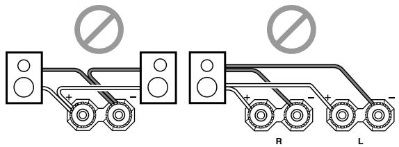
- To prevent circuitry damage, never short-circuit the positive (+) and negative (-) speaker wire.
- Be sure to connect the positive and negative cables for the speakers properly. If they are mixed up, the left and right signals will be reversed and the audio will sound
- Do not connect more than one speaker cable to one speaker terminal. Doing so may damage the TX-NR1000/TX-NR5000E.
Connecting the Speaker Cable
- Strip away approx. 5/8 inch (15 mm) of the wire insulation.
- Twist the wire ends tightly together.
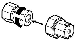
- Unscrew the speaker terminal cap.
- Insert the exposed wire end.
- Tighten speaker terminal cap.
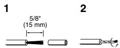
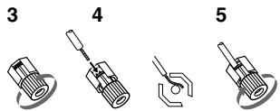
Tip:
The terminal wrench that comes with this unit is a useful tool for tightening/ loosening the speaker terminal cap.
Attaching the Speaker Labels
The positive speaker terminals on the TX-NR1000/ TX-NR5000E are color coded for easy identification. Attach the supplied speaker labels to the speaker cables, and then match the colors on the speaker cables to the corresponding terminals.
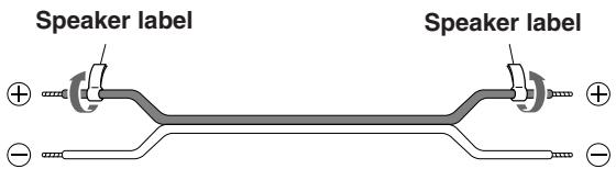
The speaker channels are colored as follows:
Front left speaker (+) : White
Front right speaker (+) : Red
Center speaker (+) :Green
Surround left speaker (+) : Blue
Surround right speaker (+) : Grey
Surround back/Zone 2 left speaker (+) : Brown
Surround back/Zone 2 right speaker (+) : Tan
Surround back right speaker
Surround back left speaker
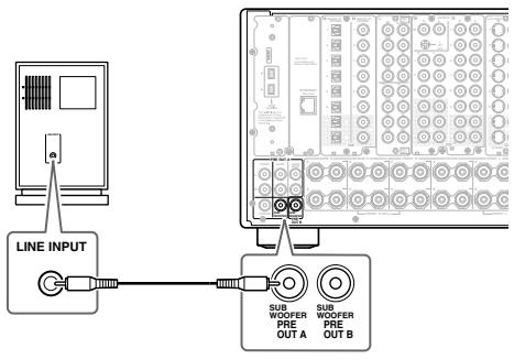
Connecting a Subwoofer
Use the SUBWOOFER PRE OUT A/B jack to connect a subwoofer with a built-in power amplifier. If your subwoofer does not have a built-in amplifier, connect an amplifier to the SUBWOOFER PRE OUT A/B jack and the subwoofer to the amplifier.
You can connect two subwoofoers for different speaker systems. You have to assign a subwoofer to the room in which it will be used (See pages 88, 89).
Connecting Auxiliary Power Amplifier (For Speaker System [A] only)
These jacks are for connecting an auxiliary power amplifier. The PRE OUT terminals on the TX-NR1000/ TX-NR5000E use the mode settings for speaker system [A].
You can use an auxiliary power amplifier to listen at louder volumes than you can with the TX-NR1000/ TX-NR5000E alone. When using a power amplifier, connect each speaker to the power amplifier.
![ONKYO TX-NR1000 - Connecting Auxiliary Power Amplifier (For Speaker System [A] only) - 1](/content/2025/01/151762/images/14ab27fdcdf216b56a55bb8efb418eeb7c1689fb36e068745238ae6c055d3703.jpg)
- Front left speaker
- Front right speaker
- Center speaker
- Surround left speaker
-
Surround right speaker
-
Surround back left speaker
- Surround back right speaker
Using the BTL Connection
To get more powerful sound output, you can make the BTL (Bridged Transless) connection using the front and surround back speaker terminals on the TX-NR1000/ TX-NR5000E. In this connection, two speaker outputs of the stereo amplifier will be used as mono output by combining the individual stereo channel outputs, allowing you to get about twice the output.
Note:
When using the BTL connection, make sure that the speaker impedance is 8 ohm or higher.
For the settings on the BTL connection, see pages 88, 89.
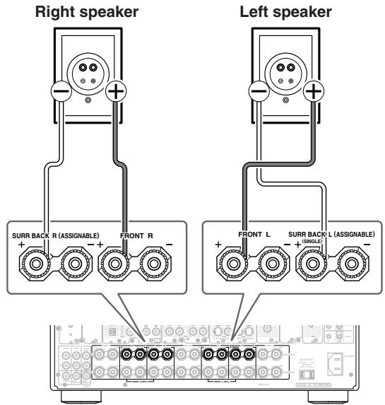
In the BTL connection, the (-) L/R speaker terminals on the TX-NR1000/TX-NR5000E will not be used.
- Connect the (+) terminal on the right speaker to the FRONT R SPEAKERS (+) terminal on the TX-NR1000/TX-NR5000E and the (-) terminal on the right speaker to the SURR BACK R SPEAKERS (+) terminal on the TX-NR1000/ TX-NR5000E.
- Connect the (+) terminal on the left speaker to the FRONT L SPEAKERS (+) terminal on the TX-NR1000/TX-NR5000E and the (-) terminal on the left speaker to the SURR BACK L SPEAKERS (+) terminal on the TX-NR1000/TX-NR5000E.
Using Bi-amp Connection
When you use bi-wiring-enabled speakers for the front speakers, you can make the bi-amp connection. In this connection, the front and surround back speaker terminals will be used for tweeter and woofer, respectively. This connection allows you to obtain high quality sound as well as maximum treble and bass performance from the tweeter and woofer, enriching your sound experience.
Caution:
- When making the bi-amp connection, make sure to remove the shorting bars connecting the high range (Tweeter) and low range (Woofer) terminals.
- When using the bi-amp connection, make sure that the speaker impedance is 8 ohm or higher.
For the settings on the bi-amp connection, see pages 88, 89.
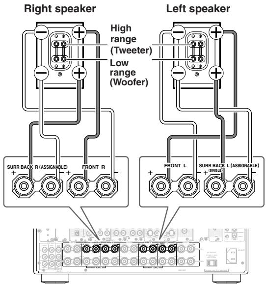
Bi-wiring-enabled speakers
- Connect the (+) tweeter terminal of the right speaker to the FRONT R SPEAKERS (+) terminal on the TX-NR1000/TX-NR5000E and the (+) woofer terminal of the right speaker to the SURR BACK R SPEAKERS (+) terminal on the TX-NR1000/TX-NR5000E.
- Connect the (-) tweeter terminal of the right speaker to the FRONT R SPEAKERS (-) terminal on the TX-NR1000/TX-NR5000E and the (-) woofer terminal of the right speaker to the SURR BACK R SPEAKERS (-) terminal on the TX-NR1000/TX-NR5000E.
- Connect the (+) tweeter terminal of the left speaker to the FRONT L SPEAKERS (+) terminal on the TX-NR1000/TX-NR5000E and the (+) woofer terminal of the left speaker to the SURR BACK L SPEAKERS (+) terminal on the TX-NR1000/ TX-NR5000E.
- Connect the (-) tweeter terminal of the left speaker to the FRONT L SPEAKERS (-) terminal on the TX-NR1000/TX-NR5000E and the (-) woofer terminal of the left speaker to the SURR BACK L SPEAKERS (-) terminal on the TX-NR1000/ TX-NR5000E.
Connecting Antennas
This chapter explains how to connect the supplied indoor FM antenna and AM loop antenna, and how to connect commercially available outdoor FM and AM antennas.
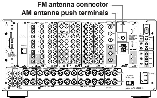
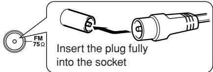
Connecting the Indoor FM Antenna
The supplied indoor FM antenna is for indoor use only.
1 Attach the FM antenna, as shown.
USA and Canadian Model
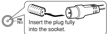
Other Models
Once your TX-NR1000/TX-NR5000E is ready for use, you'll need to tune into an FM radio station and adjust the position of the FM antenna to achieve the best possible reception.
2 Use thumbtacks or something similar to fix the FM antenna into position.
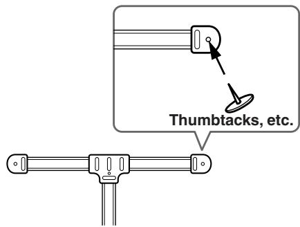
Caution: Be careful that you don't injure yourself when using thumbtacks.
If you cannot achieve good reception with the supplied indoor FM antenna, try using a commercially available outdoor FM antenna instead.
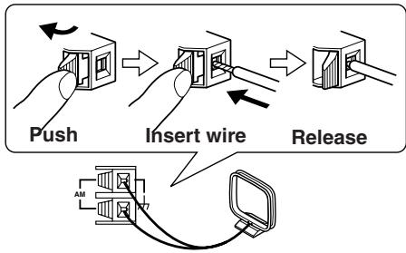
Connecting the AM Loop Antenna
The supplied indoor AM loop antenna is for indoor use only.
1 Assemble the AM loop antenna, inserting the tabs into the base, as shown.
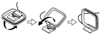
2 Connect both wires of the AM loop antenna to the AM push terminals, as shown.
(The antenna's wires are not polarity sensitive, so they can be connected in either terminal)
Make sure that the wires are attached securely and that the push terminals are gripping the bare wires, not the insulation.
Once your TX-NR1000/TX-NR5000E is ready for use, you'll need to tune into an AM radio station and adjust the position of the AM antenna to achieve the best possible reception. Keep the antenna as far away as possible from your TX-NR1000/TX-NR5000E, TV, speaker cables, and power cords.
If you cannot achieve good reception with the supplied indoor AM loop antenna, try using a commercially available outdoor AM antenna.
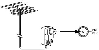
Connecting an Outdoor FM Antenna
If you cannot achieve good reception with the supplied indoor FM antenna, try using a commercially available outdoor FM antenna instead.
Notes:
- Outdoor FM antennas work best outside, but acceptable results can sometimes be obtained when installed in an attic or loft.
- For best results, install the outdoor FM antenna well away from tall buildings, preferably with a clear line of sight to your local FM transmitter.
- Outdoor antennas should be located away from possible noise sources, such as neon signs, busy roads, etc.
- For safety reasons, outdoor antennas should be situated well away from power lines and other high voltage equipment.
- Outdoor antennas must be grounded in accordance with local regulations to prevent electric shock hazards.
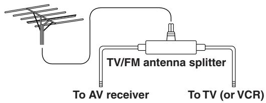
Using a TV/FM Antenna Splitter
It's best not to use the same antenna for both FM and TV reception, as this can cause interference problems. If circumstances demand it, use a TV/FM antenna splitter, as shown.
Connecting an Outdoor AM Antenna
If good reception cannot be achieved using the supplied AM loop antenna, an outdoor AM antenna can be used in addition to the loop antenna, as shown.

Outdoor AM antennas work best when installed outside horizontally, but good results can sometimes be obtained indoors by mounting it horizontally above a window. Note that the AM loop antenna should be left connected. Outdoor antennas must be grounded in accordance with local regulations to prevent electric shock hazards.
Types of Connection Cables and Terminals
In addition to the conventional terminals, the TX-NR1000/TX-NR5000E has various terminals that are capable of next-generation digital transmission.
Before connecting AV components to the TX-NR1000/TX-NR5000E, make sure that your cable type matches the terminal shape and the signal type and that the cable length is appropriate for the placement of your connected components.
Audio cables
| Cable names | Cable forms | Terminals shapes | Description |
| Optical cable | OPTICAL | The connection using these cable types transmits digital audio signals. There is no sound quality difference among these cable types. Note: Some optical cables have their own covers. Before making a connection, remove the covers. When plugging in a cable, be sure to match the connector shape with the terminal shape. Each optical terminal on the TX-NR1000/ TX-NR5000E has its own shutter-type cover. For the TX-NR1000/TX-NR5000E, plug in the optical cables so that the optical cable connector pushes the terminal cover down. | |
| Coaxial cable | COAXIAL | ||
| Audio connection cable | AUDIO | This connection transmits an analog audio signal. Plug the red connector (R) into the right channel terminal and the white connector (L) into the left channel connector. | |
| Multichannel con- nection cable | FR SUB SRF SSB | The terminals for this cable type are for DVD players that are compatible with the DVD-Audio format. This connection transmits multichannel analog audio signals. | |
| i.LINK (AUDIO) con- nection cable (4-pin (S400) type) | This connection can be used for connecting i.LINK (AUDIO)-enabled devices and to transmit digital audio signals. Also, multichannel analog audio signals from DVD-Audio or Super Audio CD format sources will be transmitted digitally. The TX-NR1000/TX-NR5000E handles only audio signals through i.LINK connection. | ||
| Ethernet cable (CAT-5 Straight type) | ETHERNET (Net-Tune) | The Ethernet cable is used for connecting multi- ple PCs or network-ready audio components that constitute a local area network (LAN). A LAN is a smaller network composed within a house or building. The connecting terminals for the Ethernet cables are often called "LAN port" or "broadband port." |
*The audio input signal from the ETHERNET (Net-Tune) or MULTI-CH IN terminal will not be output to the HDMI OUT terminal. Also, the DVD audio or SACD audio input signal from the i.LINK (AUDIO) terminal will not be output to the HDMI OUT terminal.
When you play a source in the remote zone (Zone 2 or Zone 3), the following restrictions are applied.
- When you play the audio signal from Super Audio CD or DVD-Audio format sources through the i.LINK (AUDIO) interface, the audio input signal from these sources will not be output to Zone 2 or Zone 3. With this connection, you cannot record from these sources.
- When you play the audio signal from the i.LINK (AUDIO) interface in Zone 3, only the PCM signal will be output as an analog source to the AUDIO OUT terminals. Similarly, with this connection, you can record only the PCM signal as an analog source through the AUDIO OUT terminals.
- The audio input signal from the LAN port will be output only to the AUDIO OUT terminals as an analog source.
-
When you play the audio signal from the PH or AUDIO IN terminals in Zone 3, the input source will be output only to the AUDIO OUT terminals as an analog source. Similarly, in this connection, you can record only the audio signal as an analog source through the AUDIO OUT terminals.
-
When you play the audio signal from the DIGITAL IN terminals in Zone 2, the source will be downmixed into 2-channel analog audio signal and output to the AUDIO OUT terminals.
- When you play the audio signal from the DIGITAL IN terminals in Zone 3, only the PCM signal will be output as an analog source to the AUDIO OUT terminals. Similarly, with this connection, you can record only the PCM signal as an analog source through the AUDIO OUT terminals.
- The audio input signal from the HDMI IN terminal can be output to the HDMI OUT terminal.
- The audio input signal from the MULTI-CH IN terminals in Zone 2 will be downmixed into a 2-channel source for output. You cannot play the source from the MULTI-CH IN terminals in Zone 3 and record it.
Video cables
| Cable names | Cable forms | Terminals shapes | Description |
| Component video connection cable (RCA type) | Y Y Y P B P R P R | Y P B P R | In this connection, the video signal is decom-posed into three color difference signals (Y, Pb/Cb, and Pr/Cr) and carried through three cables, which provides better video quality than the S Video connection. The terminal shape for the component video connection cable can be BNC-type or RCA-type. For the TX-NR1000/TX-NR5000E, the US model is equipped only with RCA-type termi-nals, and the other models are equipped with both RCA-type and BNC-type terminals. This connection cannot transmit information for controlling video devices (e.g., aspect ratio). |
| Component video connection cable (BNC type) | Y Y Y Y P B P R P R P R P R | Y Y P B P R P R P R | The video quality is better than with the com-posede signal. In this connection, the TX-NR1000/TX-NR5000E cannot transmit the information for controlling video devices (e.g., aspect ratio). |
| S Video connection cable | S S V D E O | S V D E O | This connection transmits the standard video signal and is widely used for various video devices such as TV and video recorder. |
| Video connection cable | V D E O | V D E O | This connection carries the video signals digi-ally. (Note that no audio signal is carried with this unit.) |
| HDMI connection cable | H D I | H D I | This connection carries the video signals digi-ally. (Note that no audio signal is carried with this unit.) |
Note:
When you play the source in the remote zone (Zone 2 or Zone 3), connect the TV or monitor to the VIDEO 1,VIDEO 2, orVIDEO 3 terminal.
- Always refer to the instructions that came with the component that you are connecting.
- Do not plug in the power cord until all connections have been properly made.
- Insert all plugs and connectors securely. Improper connections can result in noise, poor performance, or damage to the equipment.
Example: Audio connection cable

- Do not bind audio/video connection cables with power cords and speaker cables. Doing so may adversely affect the picture and sound quality.
Connecting Monitors such as TV or Projector
- This section describes the connections for displaying the video source or the operating information of the TX-NR1000/TX-NR5000E on a monitor device such as a TV or projector. Before making a connection, check the terminal types on the monitor device and acquire the necessary cables by referring to page 31.
- The TX-NR1000/TX-NR5000E incorporates a video converter, which allows you to enjoy the video source even when the connections between the playback device and the TX-NR1000/TX-NR5000E and between the TX-NR1000/TX-NR5000E and the monitors are different. When your TV or monitor has various types of input terminals, use the connection with which you can get the best video quality (For a model with no HDMI terminal, note that the input signal from the COMPONENT terminal will be output only to the COMPONENT terminal).
- The VIDEO OUT 4 and SVIDEO OUT 4 terminals can be used only for Main room A.
- When you enjoy the video source in the remote zone (Zone 2 or Zone 3), the TV or monitor should be connected to the VIDEO 1,VIDEO 2, orVIDEO 3 terminal.
*For more information on the HDMI interface, see page 43.
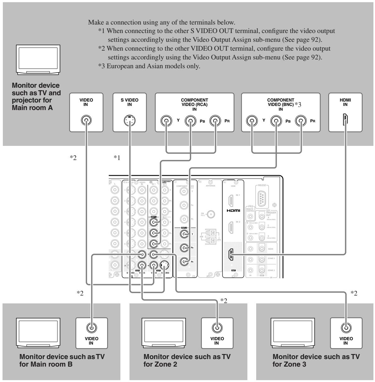
Connecting a DVD Player
- When connecting a DVD player to the TX-NR1000/TX-NR5000E, make connections for video and audio signals using digital and analog terminals. Before making connections, refer to page 30 for correct connections.
- When you want to perform analog recording of the audio signal from a DVD player or operate your RI -compatible Onkyo products via RI connections between the TX-NR1000/TX-NR5000E, you have to make analog audio signal connections. Connect the audio output terminals on the DVD player to the AUDIO IN terminals on the TX-NR1000/ TX-NR5000E using analog audio cables (RCA/phono).
- This section shows the connection example when you use the default settings of the TX-NR1000/TX-NR5000E. However, you can connect a DVD player to other terminals within the same terminal section on the TX-NR1000/ TX-NR5000E. In such case, remember to configure the audio input assignment in the Audio Assign sub-menu (See page 94) and the video input assignment in the Video Assign sub-menu (See page 95).
- For a model without a HDMI terminal, when you connect a DVD player to the COMPONENT terminals, be sure to use the COMPONENT terminal to connect a TV or projector.
For more information on the HDMI interface, see page 43.
For more information on the i.LINK (AUDIO) interface, see page 40.
DVD player
When connecting to other audio terminals within the same terminal section, configure the audio input settings accordingly using the Audio Assign sub-menu. (See page 94.)
When connecting to other video terminals within the same terminal section, configure the video input settings accordingly using the Video Assign sub-menu. (See page 95.)
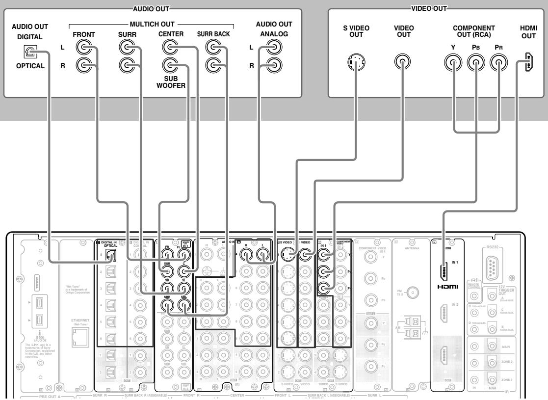
Connecting a DVD Recorder or Digital VCR (VIDEO 1)
- When connecting a DVD recorder or digital VCR to the TX-NR1000/TX-NR5000E, make connections for video and audio signals using digital and analog terminals. Before making connections, refer to page 30 for correct connections.
- This section shows the connection example when you use the VIDEO 1 as an input. In this case, you do not need additional configurations. When connecting to other terminals within the same terminal section on the TX-NR1000/ TX-NR5000E, configure the audio input assignment in the Audio Assign sub-menu (See page 94), the video input assignment in the Video Assign sub-menu (See page 95), the audio output assignment in the Audio Output Assign sub-menu (See page 91), and the video output assignment in the Video Output Assign sub-menu (See page 92).
- You can change the display name for the input source to represent the actual connected device (See page 97).
- When you want to perform analog recording of the audio signal from the digital device, you have to make analog audio signal connections. Connect the audio output terminals on the digital device to the AUDIO IN terminals on the TX-NR1000/TX-NR5000E using analog audio cables (RCA/phono).
- For a model without a HDMI terminal, when you connect a DVD recorder or digital VCR to the COMPONENT terminals, be sure to use the COMPONENT terminals to connect a TV or projector.
*For more information on the HDMI interface, see page 43.
*For more information on the i.LINK (AUDIO) interface, see page 40.
Example for connecting with the VIDEO 1 as input
Digital video recorder (DVD recorder, digital VCR)
When connecting to other audio terminals within same terminal section, configure the audio input settings accordingly using the Audio Assign sub-menu (See page 94).
When connecting to other audio terminals within the same terminal section, configure the audio output settings accordingly using the Audio Output Assign submenu (See page 91).
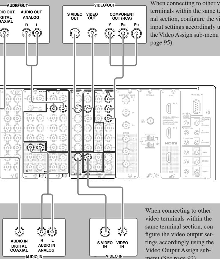
When connecting to other video terminals within the same terminal section, configure the video output settings accordingly using the Video Output Assign submenu (See page 92).
Connecting a VCR (VIDEO 2,VIDEO 3)
- When connecting a VCR to the TX-NR1000/TX-NR5000E, make connections for video and audio signals. Before making connections, refer to page 30 for correct connections.
- This section shows the connection example when you use VIDEO 2 or VIDEO 3 as an input. In this case, you do not need additional configurations. When connecting to other terminals within the same terminal section on the TX-NR1000/TX-NR5000E, configure the audio input assignment in the Audio Assign sub-menu (See page 94), the video input assignment in the Video Assign sub-menu (See page 95), the audio output assignment in the Audio Output Assign menu (See page 91), and the video output assignment in the Video Output Assign menu (See page 92).
- You can change the display name for the input source to represent the actual connected device (See page 97).
- For a model without a HDMI terminal, when you connect a VCR to the COMPONENT terminals, be sure to use the COMPONENT terminals to connect a TV or projector.
*For more information on the HDMI interface, see page 43.
*For more information on the i.LINK (AUDIO) interface, see page 40.
Example for connecting with the VIDEO 2 as input
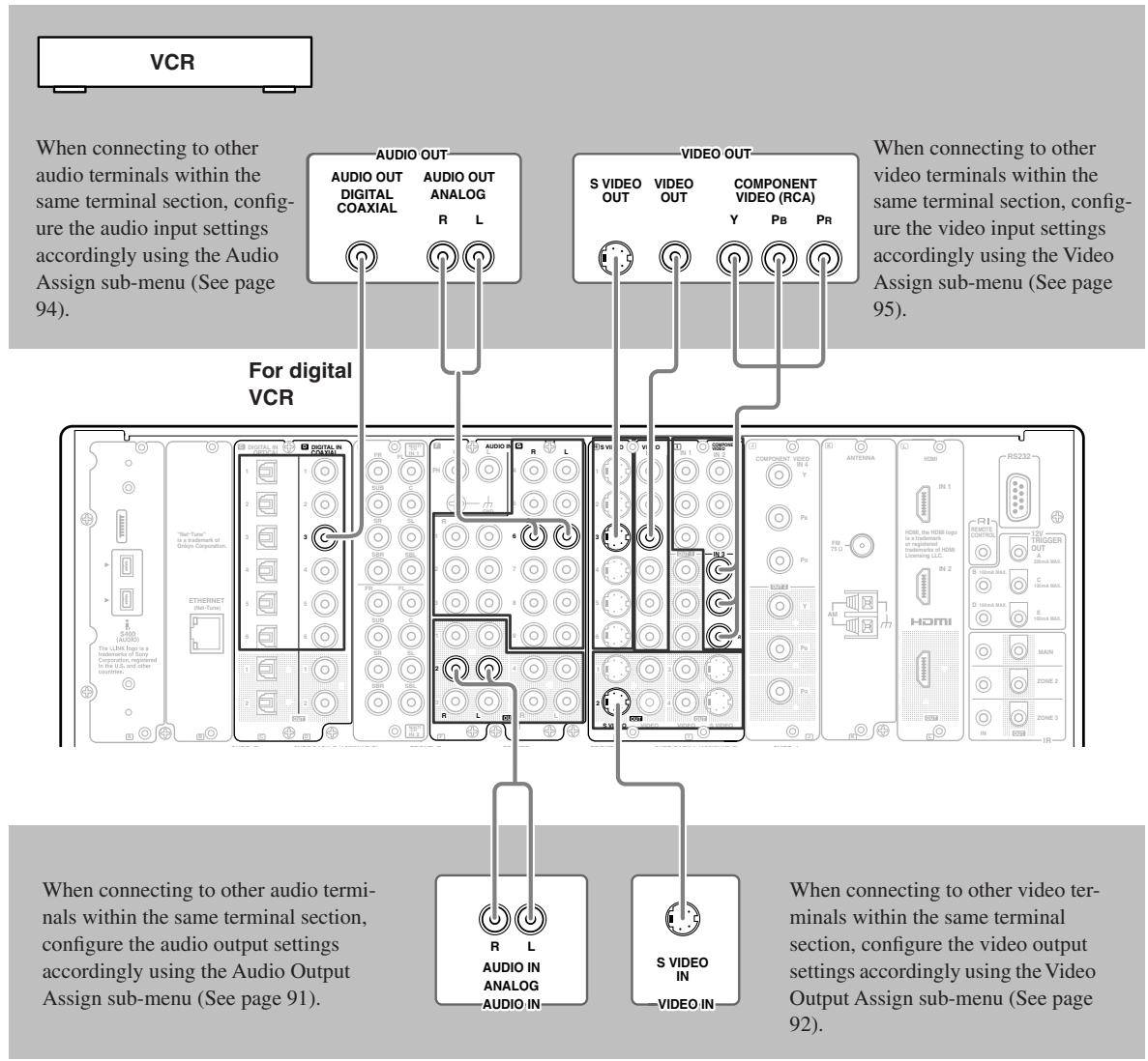
Example for connecting with the VIDEO 3 as input
VCR
When connecting to other audio terminals within the same terminal section, configure the audio input settings accordingly using the Audio Assign sub-menu (See page 94).
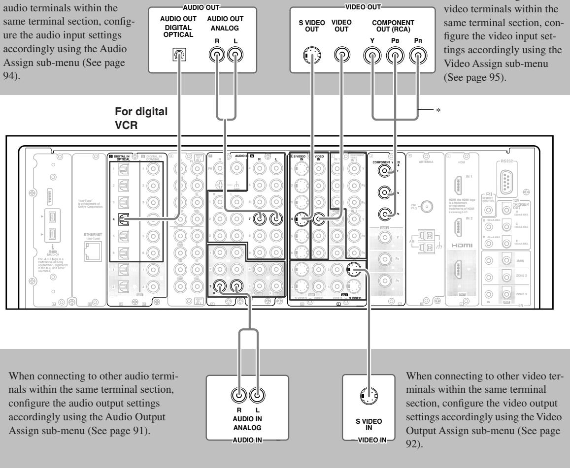
When connecting to other video terminals within the same terminal section, configure the video input settings accordingly using the Video Assign sub-menu (See page 95).
*European and Asian models use the BNC type component terminals, and other models use the RCA type.
Connecting a DBS Tuner, DBS TV, or BS/CS Tuner
- When connecting a DBS tuner, DBS TV, or BS/CS tuner to the TX-NR1000/TX-NR5000E, make connections for video and audio signals using digital and analog terminals. Before making connections, refer to page 30 for correct connections.
- This section shows the connection example when you use the VIDEO 4 or VIDEO 5 as an input. In this case, you do not need additional configurations. When connecting to other terminals within the same terminal section on the TX-NR1000/TX-NR5000E, remember to configure the audio input assignment in the Audio Assign sub-menu (See page 94) and the video input assignment in the Video Assign sub-menu (See page 95). When you use the SVIDEO terminal for connection, you should configure the Video Assign sub-menu.
- You can change the display name for the input source to represent the actual connected device (See page 97).
- For a model without a slot for the HDMI terminal, when you connect a BS/CS tuner or LD player to the COMPONENT terminals, be sure to use the COMPONENT terminals to connect a TV or projector.
*For more information on the HDMI interface, see page 43.
*For more information on the i.LINK (AUDIO) interface, see page 40.
Example for connecting with the VIDEO 4 as input
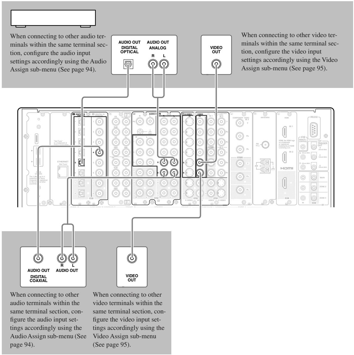
Example for connecting with the VIDEO 5 as input
Connecting a Portable DVD Player or Video Camcorder
- When connecting a portable DVD player or video camcorder to the TX-NR1000/TX-NR5000E, use the VIDEO 7 INPUT terminals on the front panel.
- You can change the display name for the input source to represent the actual connected device (See page 97).
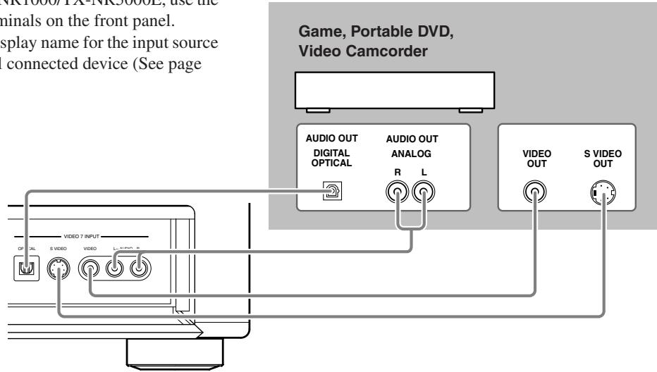
Connecting a CD Player, Turntable or Tuner
- When connecting a CD player to the TX-NR1000/TX-NR5000E, make connections using digital or analog terminals. Before making connections, refer to page 30 for correct connections. This section shows the connection example when you use the default audio input assignment settings. However, when you use coaxial cables for digital audio signals, connect the CD player to any terminal between the AUDIO IN DIGITAL COAXIAL 1 and 6, and remember to configure the audio input assignment settings in the Audio Assign sub-menu (See page 94).
- When connecting a turntable, use the PH terminal. The PH terminal on the TX-NR1000/TX-NR5000E is designed for turntables that use a moving magnet (MM) cartridge. When you want to use a turntable with a moving coil (MC) cartridge, connect the turntable through a step-up transformer or head amplifier.
- If you assign other terminals to the PHONO input source, you need to configure the audio input assignment settings in the Audio Assign sub-menu (See page 94).
- When a turntable is equipped with a ground wire, connect the wire to the GND terminal on the TX-NR1000/ TX-NR5000E. However, some turntables may produce noise when the ground wire is connected to the TX-NR1000/ TX-NR5000E. In such a case, you do not have to connect the ground wire.
- When you want to perform analog recording of the audio signal or operate your RI -compatible Onkyo products via RI connections between the TX-NR1000/TX-NR5000E, you have to make analog audio signal connections. Connect the audio output terminals on the source device to the AUDIO IN terminals on the TX-NR1000/TX-NR5000E using analog audio cables (RCA/phono).
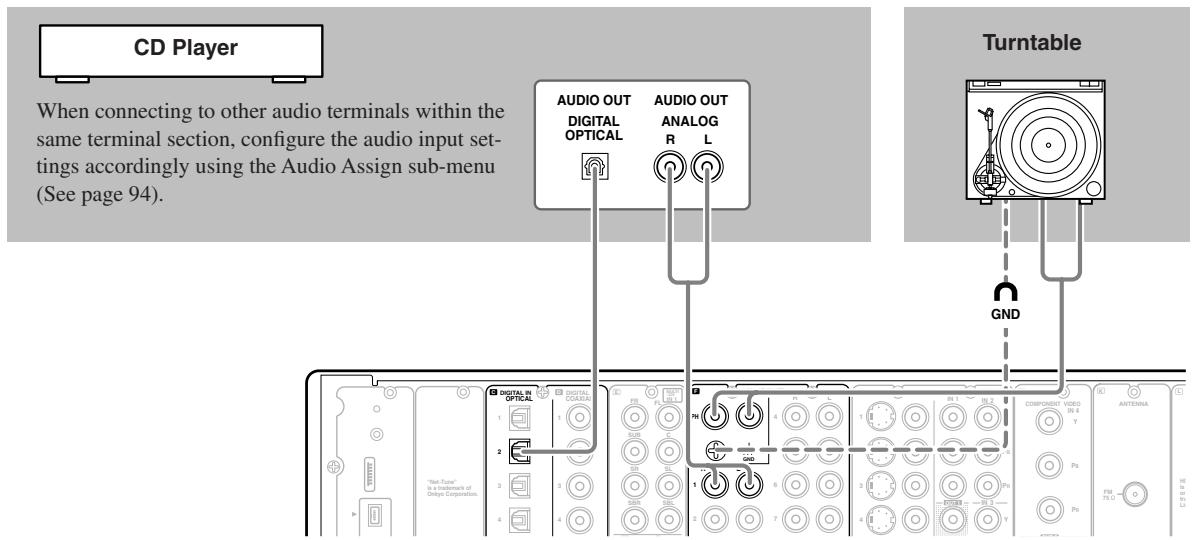
Connecting a Recording Device such as MD Recorder, DAT Deck, CD Recorder or Cassette Deck
- When connecting a MD recorder, DAT deck or CD recorder to the TX-NR1000/TX-NR5000E, make connections using digital or analog terminals. Before making connections, refer to page 30 for correct connections.
- Connect a cassette or DAT tape deck to TAPE1, and an MD or CD recorder to TAPE 2.
- When you connect a cassette deck to the TX-NR1000/TX-NR5000E, be sure to use only analog audio terminals. In the initial settings, no terminal of this unit is assigned to a REC terminal of the cassette deck. To achieve the assignment, connect the REC terminal of the cassette deck to any of the AUDIO OUT 1 to 5 terminals and set the terminal to "Tape 1 Rec Out" in the Audio Output Assign sub-menu (See page 91). In addition, you can switch the input source "TAPE2" to MD or CDR. Press the [TAPE 2] button on the front panel to display "TAPE 2," then press the [TAPE 2] button again and hold it for 3 seconds. This changes the display to "MD." If you wish to change it to "CDR," release the button once, and press and hold it again for 3 seconds. This operation enables you to operate Onkyo's MD or CD recorders with the remote controller of this unit (Please note that the RI connection is required).
- When connecting to other terminals, remember to configure the audio input assignment in the Audio Assign submenu (See page 94) and the audio output assignment in the Audio Output Assign sub-menu (See page 91).
- You can change the display name for the input source to represent the actual connected device (See page 97).
- When you want to perform analog recording of an audio signal or operate your RI -compatible Onkyo products via RI connections between the TX-NR1000/TX-NR5000E, you have to make analog audio signal connections. Connect the audio output terminals on the source device to the AUDIO IN terminals on the TX-NR1000/TX-NR5000E using analog audio cables (RCA/phono).
Example for connecting with the TAPE 1 as input
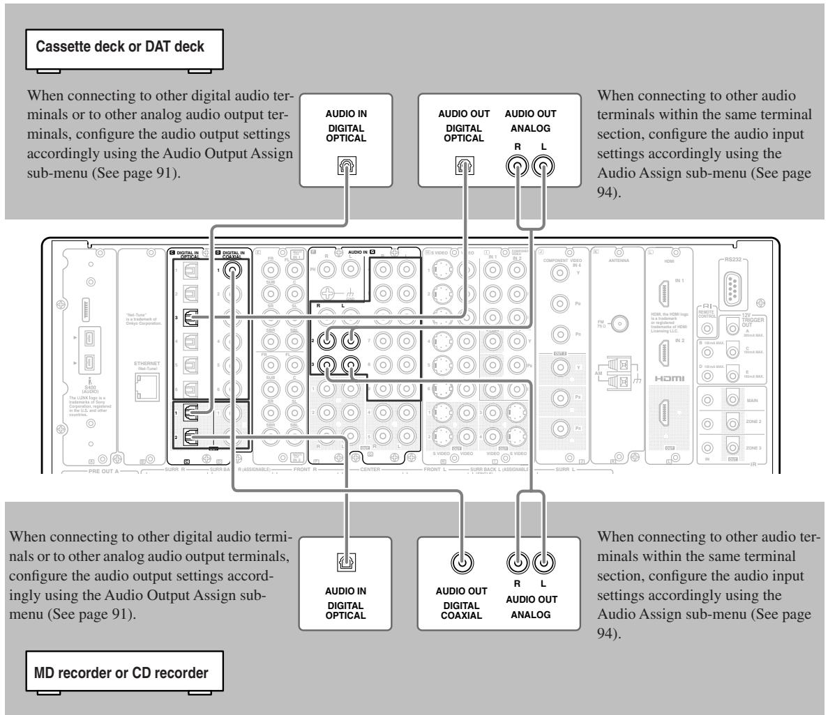
Example for connecting to the TAPE 2 as input
Connection Using the i.LINK (AUDIO) Terminal ( i ) (Other than Chinese model)
What is i.LINK
i.LINK is an appellation of IEEE1394, which is the digital interface standard defined by the Institute of Electrical and Electronics Engineers (IEEE).
Connecting i.LINK (AUDIO)-supported devices allows high speed transfer of data such as digital sound between the linked devices, and their control.
What is i.LINK (AUDIO)
The TX-NR1000/TX-NR5000E supports "i.LINK (AUDIO)" of the i.LINK transfer format. Accordingly, "i.LINK (AUDIO)" must also be supported for other devices that you want to connect to the TX-NR1000/TX-NR5000E. The TX-NR1000/TX-NR5000E does not support other i.LINK transfer formats such as "MPEG-2 TS" used for BS digital broadcasts or "DV" used for DVD recorders, digital video, etc. The TX-NR1000/TX-NR5000E connected to other i.LINK(AUDIO)-supported devices via i.LINK cable enables you to transfer multichannel digital sound such as DVD-Audio and SACD (video signal is not supported).
Even when multiple devices are connected to each other, you can perform data transfer and control of target devices via another device.
The IEEE interfaces on the TX-NR1000/TX-NR5000E are designed conforming to the standards below.
- IEEE Std 1394a-2000, Standard for a High Performance Serial Bus
- IEC60958 bitstream, DVD-Audio, and SACD in the AM824 Sequence adaptation layers of Audio and Music Data Transmission Protocol 2.0
Copyright Protection System
The TX-NR1000/TX-NR5000E supports the DTCP (Digital Transmission Contents Protection) system. The DTCP system uses technologies for data encryption and authentication during the data transfer between the i.LINK-connected digital devices in order to protect the copyright of the content against illegal duplication. To enjoy replaying DVD-Audio, etc., the DTCP must also be supported by other devices connected to the TX-NR1000/TX-NR5000E.
How to Make a Connection through the i.LINK (AUDIO) Interface
Use the S400 4-pin i.LINK (AUDIO) cable to connect the i.LINK (AUDIO) terminal on the TX-NR1000/ TX-NR5000E to the i.LINK (AUDIO) terminal on the i.LINK (AUDIO)-enabled device.
- When using the i.LINK connection, you need to configure the audio input assignment settings in the "i.LINK" section of the Audio Assign sub-menu (Some i.LINK-connected devices may require audio output settings).
- The TX-NR1000/TX-NR5000E supports only audio signal transmission through the i.LINK (AUDIO) interface. When connecting video devices, you need to make a connection using other terminals for video signal.
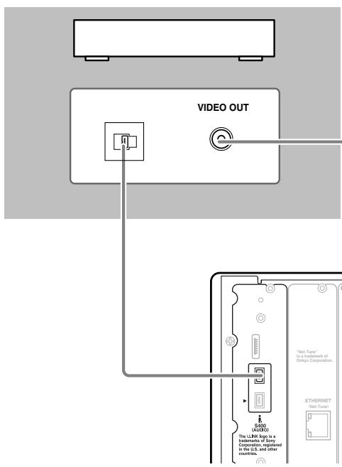
Note:
If any other Onkyo product is connected to the TX-NR1000/ TX-NR5000E via i.LINK, system operation can be achieved via i.LINK cable. In that case, disconnect the R1 connection as it may introduce errors.
In addition to the i.LINK audio connection, make sure to connect the terminals for images such as VIDEO and/or SVIDEO terminals.
Interconnection of i.LINK (AUDIO)-supported Devices
The i.LINK connection allows for data transfer, even if the TX-NR1000/TX-NR5000E is connected to other devices via another i.LINK (AUDIO)-supported device. You can connect up to 17 devices in a daisy chain (in-line) connection arrangement using the i.LINK connection.
Example: TX-NR1000/TX-NR5000E
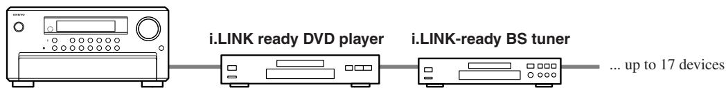
For devices in a branched connection arrangement, you can connect up to 63, as long as they have three or more i.LINK (AUDIO) terminals.
Example: TX-NR1000/TX-NR5000E
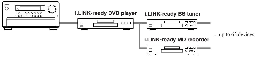
Be sure to avoid the looped connection arrangement of devices as shown below. The output signals should not be returned to the original signal output device, which may cause device failure.
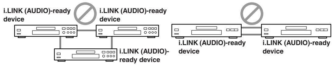
Notes:
- Do not connect any devices that do not support i.LINK (AUDIO), such as "MPEG-2 TS" ready devices used for BS digital broadcasts and "DV" ready devices used for digital video, etc.
- Do not connect/disconnect i.LINK cable to or from other devices, connect additional devices, or turn them on/off while any i.LINK (AUDIO)-ready device is playing. Otherwise, the audio sound may be interrupted.
- Some i.LINK (AUDIO)-ready devices cannot transfer data when the power mode is set to standby or off. Refer to the individual User Manual of the i.LINK (AUDIO)-ready device you want to connect.
- i.LINK (AUDIO)-ready devices have their own maximum data transfer rate: either S100 (100 Mbps), S200 (200 Mbps) or S400 (400 Mbps). The rate label is located near the i.LINK (AUDIO) terminals. The TX-NR1000/ TX-NR5000E has a maximum data transfer rate of 400 Mbps. However, this may decrease depending on the specifications or the maximum data transfer rate of devices connected to the TX-NR1000/TX-NR5000E. It is recommended to connect devices with the same maximum data transfer rate.
“Mbps” stands for “mega bits per second” which indicates the maximum data size transferred per second. For example, 400 Mbps indicates that 400 mega bits of data can be transferred every second. - The i.LINK feature does not assure successful connectivity between all i.LINK (AUDIO)-ready devices. Successful data transfer and control signal communications depend on the individual features of each device.
How to Configure i.LINK Connections
Selecting a Device
When the i.LINK connection is ready, you can use the setup menu to select any device which is connected via i.LINK. Once you have configured the i.LINK setting, the next time you select the input source, it will be selected as the playing source.
Using Remote Control
- Press the [INPUT] button, and then turn the scroll wheel to select any source for setting.
- Press the scroll wheel, and then press the [SETUP] button.
- Use the [] / [] buttons to select "Input Setup," and then press the [ENTER] button.
- Use the [] / [] buttons to select "Audio Assign," and then press the [ENTER] button.
- Use the [] / [] buttons to select "g.i.LINK."
- Use the [] / [] buttons to select any device.
If you do not want to hear audio sound regardless if the i.LINK connection is ready, select "No."
Using Control Buttons on TX-NR1000/TX-NR5000E
- Select any input source, and then press the [SETUP] button.
- Turn the [SELECT/PRESET] dial to select "Input Setup," and then press the dial.
- Turn the [SELECT/PRESET] dial to select "Audio Assign," and then press the dial.
- Turn the [SELECT/PRESET] dial to select "g. i.LINK," and then press the dial.
- Turn the [CONTROL/TUNING] dial to select any device.
If you do not want to hear audio sound regardless if the i.LINK connection is ready, select "No."
Using Useful Functions While the i.LINK Connection is Ready
If any other Onkyo product is connected to the TX-NR1000/TX-NR5000E via i.LINK and assigned as a input source (Audio Assign), you can use the following functions. The RI connection must be disconnected to use them.
i.LINK Selector Change
When the i.LINK-connected device starts playing, the input source will automatically be changed to the one assigned to the device even if another input source has been selected. See page 120 for detailed operations.
Note:
You cannot hear audio sound of i.LINK-connected devices in Zone 2.
Control of DVD Player
You can control a DVD player by emitting signals from the remote controller to the TX-NR1000/TX-NR5000E.
Auto Start (Wakeup Setup)
While the TX-NR1000/TX-NR5000E is in standby mode, you can configure the setting of any i.LINK-connected device. See page 120 for detailed operations.
OSD for DVD
If DVD player is connected to the TX-NR1000/TX-NR5000E via i.LINK, you can output the OSD of the TX-NR1000/TX-NR5000E on a TV, even if a DVD player is directly connected to the TV. You can configure the setting to specify the display area on the TV, for example, right or left side of the screen. When multiple devices are connected, you can select any specific device through which the output is sent. This function is also available in Zone 2. See page 120 for detailed operations.
Note:
While the Intelligent Monitor is used, do not change mode to standby, nor turn on/off the player.
DVD Output Synchronization
You can select on/off of the i.LINK (AUDIO) output of a DVD player from the TX-NR1000/TX-NR5000E. See page 120 for detailed operations.
Connection Using HDMI Terminals
About the HDMI (High Definition Multimedia Interface)
The High Definition Multimedia Interface (HDMI) is an interface standard for next-generation TV, designed to connect between STB (Set Top Box) and display digitally in the home, responding to technological changes such as digitalization of TV broadcasting.
In addition to the existing features provided by the Digital Visual Interface (DVI)*1 standard, HDMI allows transmission of both audio and control signals. Moreover, multiple cables are required for video, audio, and control signals in conventional connections, but the HDMI interface allows you to make a connection through a single HDMI cable, thus enabling transfer of digital video and sound data between HDMI-supported devices.
In principle, the HDMI video stream (video signals) is compatible with the DVI. You can use the HDMI-DVI conversion cables to connect with TVs or monitors that are outfitted with DVI terminals, though video images may not be visible depending on the combination of devices. The TX-NR1000/TX-NR5000E uses HDCP; you can enjoy pictures on HDCP ready monitors.
The HDMI interfaces on the TX-NR1000/TX-NR5000E are designed to conform to the standards below.
High-Definition Multimedia Interface Specification Informational Version 1.0
Copyright Protection System
The TX-NR1000/TX-NR5000E supports High-bandwidth Digital Contents Protection (HDCP) ^*2 , technology to protect copyright of digital video signals against illegal duplication. HDCP must also be supported on the devices connected to the TX-NR1000/TX-NR5000E. Use the HDMI cable supplied with the product or those from the marketplace to connect the HDMI OUT terminal on the TX-NR1000/TX-NR5000E with the HDMI input terminals on TVs or monitors.
1 DVI (Digital Visual Interface): The digital display interface standard set by DDWG ^3 in 1999.
2 HDCP (High-bandwidth Digital Contents Protection): The video data encryption technology for DVI developed by Intel. This technology is designed to protect the video content and a HDCP-compliant DVI receiver is required to play the encrypted video content.
3 DDWG (Digital Display Working Group): The standardization group for digital interface for display, operated mainly by Intel, Silicon Image, FUJITSU, and Hewlett-Packard (Compaq Computer).
How to Make a Connection through the HDMI Interface
Use the HDMI cable to connect the HDMI terminals on the TX-NR1000/TX-NR5000E and on an HDMI-enabled device such as a DVD player, TV, or projector.
Set HDMI to 1 or 2 in the Video Assign sub-menu according to the connected device you wish to use. In the initial settings, 1 is assigned to DVD, and 2 to Video 1.
Basically, the HDMI can transmit audio signals. However in order to playback the audio signal with the TX-NR1000/ TX-NR5000E, make a separate digital connection with a DVD player or other devices, since the TX-NR1000/ TX-NR5000E cannot playback any audio signals supplied from its HDMI IN 1/2 terminals.
- When other input source than 1 or 2 is selected, analog/digital audio signals and analog video signals will be converted into the HDMI format and output through the HDMI OUT terminal (In the initial settings, no audio signal is output. Appropriate setting should be made in the Audio Output Assign sub-menu).
- Analog audio signals will be output in the PCM format. Digital audio signals will be output through the HDMI OUT terminal only if the connected TV or projector can playback the digital audio signals.
A TV or projector that supports PCM audio signals only, for example, cannot playback audio signals in the Dolby Digital format supplied as an input source to the TX-NR1000/TX-NR5000E. In order to properly playback the audio signals in this case, the player should be configured to output the PCM signals.
When an analog audio connection is made on the TX-NR1000/TX-NR5000E, analog audio signal is output in the PCM format.
Connection example when the source selection is performed on the TX-NR1000/TX-NR5000E
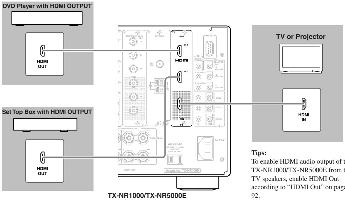
Connection example for higher video quality
When connecting an AV component equipped with the HDMI input terminal, you can use the connecting layout shown below.
Before making a connection, read the instruction manual of the connected device thoroughly.
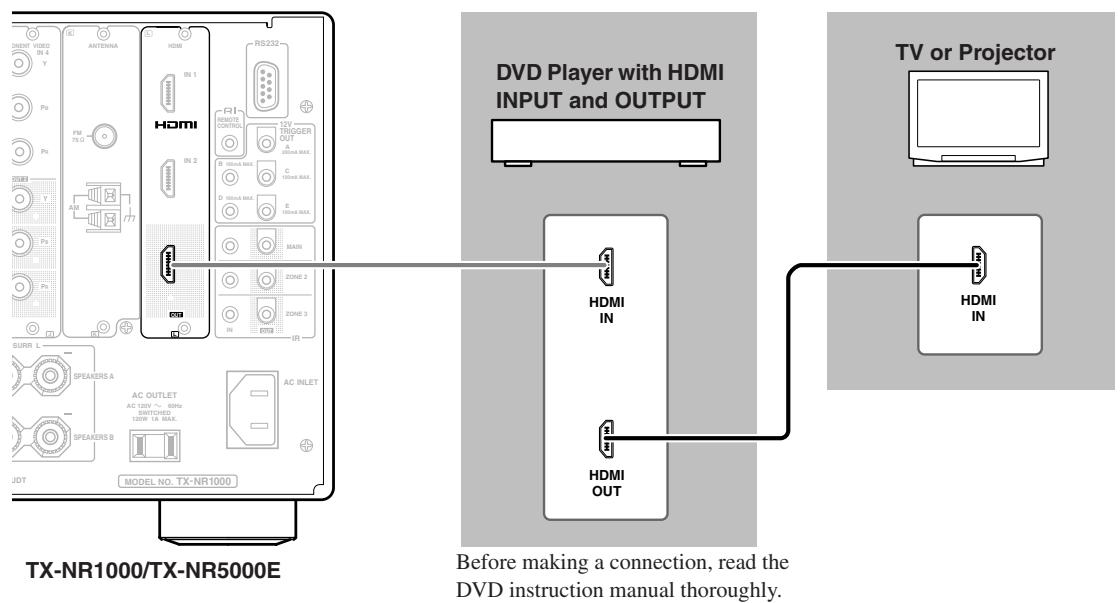
Connecting Components not Reached by the Remote Controller Signals (IR IN/OUT)
In order to use the remote controller to control the TX-NR1000/TX-NR5000E from a remote location, you will need to prepare a multiroom kit (sold separately) such as one listed below:
- Onkyo's Multi-Room System kits (IR Remote Controller Extension System)
- Multiroom A/V distribution and control system such as those from Niles® and Xantech®
RF Receivers can also be used with the remote controller to control the TX-NR1000/TX-NR5000E from a remote location. To use RF Receivers, set the Transmission Signal Format setting to "RF" (See page 141 for details).
If Remote Controller Signal Does not Reach the TX-NR1000/TX-NR5000E Remote Sensor
Effective Sensor Layout
Example for the main room
If the TX-NR1000/TX-NR5000E is located inside a cabinet or other enclosure where the infrared rays from the remote controller cannot enter, then operation with the remote controller will not be possible. In such a case, it will be necessary to install a remote sensor at a location outside of the cabinet so that the infrared rays from the controller can be sensed.
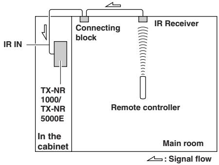
Example for the remote zone (Zone 2/Zone 3)
The IR IN input allows you to control the TX-NR1000/ TX-NR5000E from the remote zone (Zone 2/Zone 3) with the remote controller even though the remote zone may be on the other side of the building from the main zone. The diagram below shows how to make the proper connections for the remote zone.
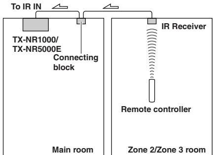
: Signal flow
Making Sensor Connections
When you place the IR receiver in the main room, connect the cable from the connecting block to the IR IN MAIN terminal. When you place the IR receiver in the remote zone, connect the cable from the connecting block to the ZONE 2 or ZONE 3 terminal accordingly. Make the connection as shown below. Do not plug any equipment into the power outlet until all the connections are complete.
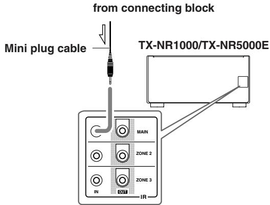
Connecting Components not Reached by the Remote Controller Signals (IR IN/OUT)—Continued
If Remote Controller Signal Does not Reach Other Components
Effective Sensor Layout
In this situation, you will need to use a commercially available IR emitter. Connect the mini plug of the IR emitter to the IR OUT terminal on the TX-NR1000/ TX-NR5000E and then place the IR emitter on the remote sensor of the component or facing it. When the IR emitter is connected, only the signal input to the IR IN terminal is output to the IR OUT terminal. The signal input from the remote sensor on the front of the TX-NR1000/TX-NR5000E will not be output to the IR OUT terminal.
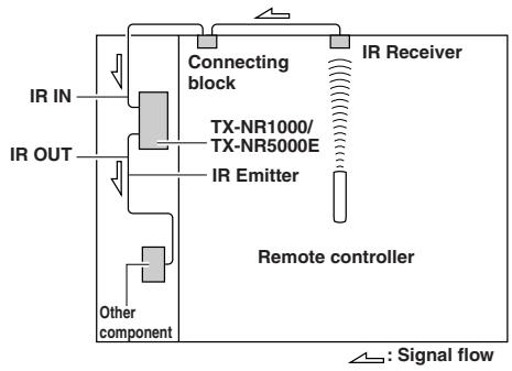
Making Sensor Connections
When you place the IR receiver in the main room, connect the cable from the connecting block to the IR OUT MAIN terminal. When you place the IR receiver in the remote zone, connect the cable from the connecting block to the ZONE 2 or ZONE 3 terminal accordingly.
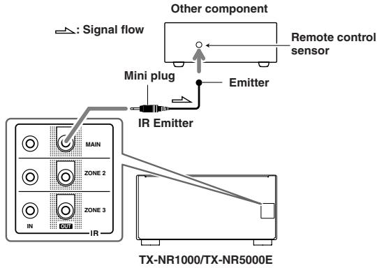
Using an External Device with 12V Trigger Terminal
You can automatically turn on the connected AV components with the output signal from the TX-NR1000/ TX-NR5000E's 12V TRIGGER OUT terminal.
Making a Connection
Connect the 12V TRIGGER OUT terminal on the TX-NR1000/TX-NR5000E to the 12V TRIGGER IN terminal on other components. Every 12V TRIGGER OUT terminal can be connected to the components whether they are placed in the main room, Zone 2, or Zone 3.
The TX-NR1000/TX-NR5000E has five 12V TRIG-GER OUT terminals and the maximum currents to be connected are as follows:
A: 200mA
B, C, D and E: 100mA
After making connections, configure the association between the room (zone) and the component to be turned on (Refer to "12V Trigger Assign" under "Input Setup" on page 98).
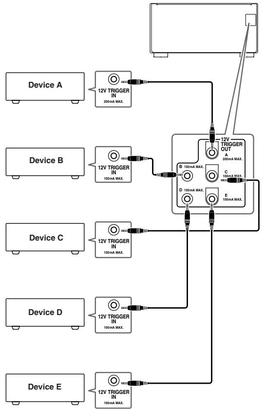
Connecting R1-compatible AV Components
The RI terminal on the TX-NR1000/TX-NR5000E is for connecting other Onkyo components equipped with the same RI terminal. When a component is connected to the RI terminal, it can be operated by the remote controller supplied with the TX-NR1000/TX-NR5000E. In addition, when you connect a component to the RI terminal, you can also perform the system operations given below.
Power on/ready function
When the TX-NR1000/TX-NR5000E is in the standby state, if an RI-connected component is turned on, the TX-NR1000/TX-NR5000E also turns on and the input source selected at the TX-NR1000/TX-NR5000E automatically switches to that component.
Be aware that this function will not work if the power cord for the RI-connected component is connected to the AC OUTLET on the TX-NR1000/TX-NR5000E, or if the TX-NR1000/TX-NR5000E has already been turned on.
Direct change function
When the play button is pressed on an RI-connected component, the input source selected at the TX-NR1000/TX-NR5000E automatically changes to that component.
Power off function
When the TX-NR1000/TX-NR5000E is placed in the standby state, all RI-connected components are also automatically put into the standby state.
Also, if you press the [ON] button on the TX-NR1000/ TX-NR5000E remote controller while the TX-NR1000/ TX-NR5000E is turned on, all RI-connected components (DVD players, CD players, MD recorders, tuners, etc.) are also turned on.
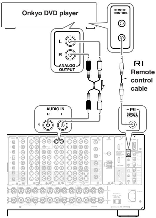
Connections for Remote Control (R1)
To connect components using the RI terminal, simply connect a remote control cable from this RI terminal to the RI terminal of the other component. An RI remote control cable with a 1/8 inch (3.5 mm) miniature two-conductor plug comes with every cassette tape deck, compact disc player, MD recorder, and DVD player that has an RI terminal.
- When performing operations with R I -connected components using the R I system, do not use the remote zone (Zone 2/Zone3).
- For remote control operation, the audio connection cables must also be connected.
- If a component has two RI terminals, you can use either one to connect to the TX-NR1000/ TX-NR5000E. The other one can be used to daisy chain with another component.
- With Onkyo DVD players, you can enter the pre-program code so that you can operate the DVD player directly with the remote controller without connecting the RI terminals (See page 129).
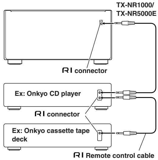
Basic Operation of Remote Controller Buttons
The remote controller supplied with the TX-NR1000/TX-NR5000E is a multifunctional remote controller, so you can operate not only the TX-NR1000/TX-NR5000E but also AV components connected to the apparatus and components placed in another room. The basic operations are explained here. It is recommended that you read and understand this page before starting actual operations. This explanation focuses on remote controller operations.
To Operate the TX-NR1000/TX-NR5000E (AMP Mode)
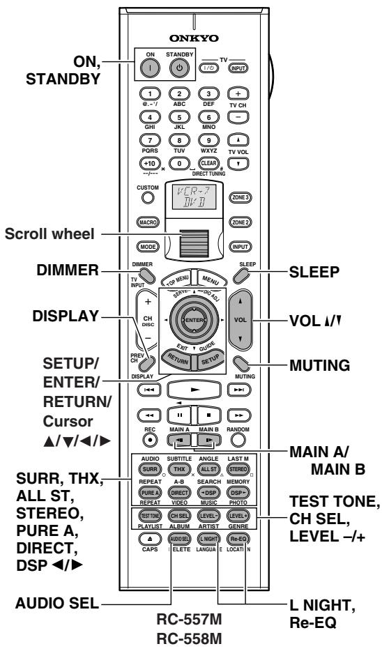
1 Press the scroll wheel.
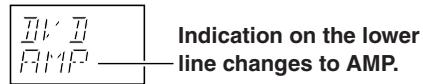
2 When the remote controller is in AMP mode, the following functions are available:
ON/STANDBY: Press to set power on/standby.
MAIN A: Used when driving the speaker that has been set to "Main A" in the Speaker Configuration sub-menu.
MAIN B: Used when driving the speaker that has been set to "Main B" in the Speaker Configuration sub-menu.
DIMMER: Used when changing brightness of the display window.
SETUP/RETURN/ENTER/Cursor / / /
): Used when operating the setup menu.
DISPLAY: Used when switching the display.
THX/SURR/PURE A/DIRECT/ALL ST/
STEREO/DSP: Used when switching the listening mode.
TEST TONE/CH SEL/LEVEL-/-+: Used for the test tone, or when temporarily changing the sound volume level.
AUDIO SEL: Used when switching the sound signal.
SLEEP: Used when setting the sleep timer.
VOL 1/1: Used when adjusting the sound volume.
MUTING: Used to temporarily turn off the sound immediately.
L NIGHT: Used when switching the dynamic range.
Re-EQ: Used when applying the Re-EQ effect.
To Select an Input Source
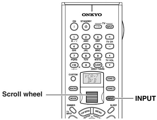
1 Press the [INPUT] button.
The [INPUT] button lights.
2 Roll the scroll wheel.
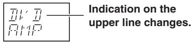
When you perform the procedures on the TX-NR1000/ TX-NR5000E, use the input source buttons on the front panel.
To Operate a Connected Component (Mode Switching)
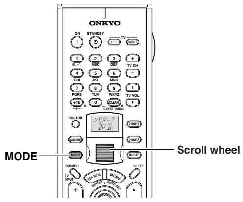
1 Press the [MODE] button.
The [MODE] button lights.
2 Roll the scroll wheel.
Indication on the lower line I1I, H changes to indicate the selected component mode.
Before operating the connected component, follow the instructions on pages 124 through 133 to make appropriate settings using the remote controller.
To Select a Source in Zone 2 or Zone 3
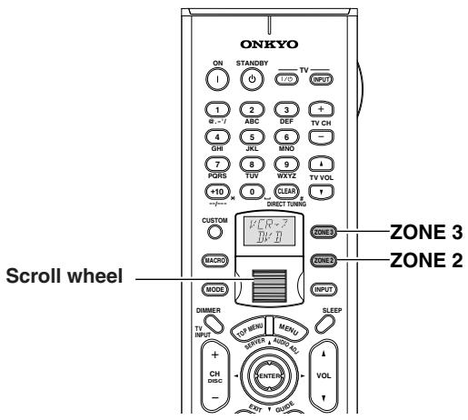
1 Press the [ZONE 2] or [ZONE 3] button.
The [ZONE 2] or [ZONE 3] button lights.
2 Roll the scroll wheel.
Indication on the upper line changes to indicate the selected input.
When you perform the procedures on the TX-NR1000/ TX-NR5000E, press the [ZONE 2] (or [REC/ZONE 3]), and turn the [SELECT/PRESET] (or [CONTROL/TUNING]).
To Perform a Macro Operation
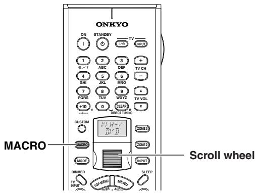
Before performing the following procedure, complete your macro settings (See page 137).
1 Press the [MACRO] button.
The [MACRO] button lights.
2 Roll the scroll wheel to select the macro's number, and then press the scroll wheel.
HACRO
Customizing Your Remote Controller
Use the [CUSTOM] button "to enter the remote controller code for another apparatus to this remote controller," "to make this remote controller learn specified operations from the remote controller for another apparatus," or "to make this remote controller learn a series of operations with macro functions" according to the configuration you are using. For detailed information, see pages 136-142.
Connecting the Power/Basic Operations
- Before you plug in the TX-NR1000/TX-NR5000E, confirm that all connections have been made properly.
- Turning on the power may cause a momentary power surge, which might interfere with other electrical equipment on the same circuit, such as computers. If this happens, use a wall outlet on a different circuit.
(All models other than USA, Canadian, and Australian models)
The TX-NR1000/TX-NR5000E is shipped with the main power (POWER) switch in the on position (ON). When the power cord is plugged in for the first time, the TX-NR1000/TX-NR5000E will automatically enter the standby state and the [STANDBY] indicator will light (same condition after step 2 below on the left column).
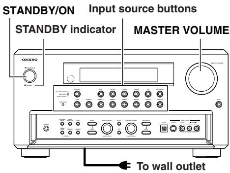
(USA, Canadian, and Australian models)
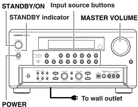
(Other models)
Turning on the Power
| 1 POWER ON OFF STANDBY | Plug the power cord into an AC wall outlet. (USA, Canadian, and Australian models) The [STANDBY] indicator will light up. (Other models) Press the [POWER] switch to set the TX-NR1000/TX-NR5000E to standby state. The [STANDBY] indicator will light up. |
| 2 STANDBY/ON TURN OFF | Press the [STANDBY/ON] button to turn on the TX-NR1000/ TX-NR5000E. The display will light up and the [STANDBY] indicator will turn off. If you press the [STANDBY/ON] button again, the TX-NR1000/TX-NR5000E returns to the standby state. |
Note:
Any components connected via RI will also be turned on when the remote controller's [ON] button is pressed.
Operating on the TX-NR1000/ TX-NR5000E
| 1 | Select an input source. Press the input source button. *You cannot listen to a source in main room A, and to another source in main room B. |
| 2 | Start playing the device selected. When playing a picture device such as a DVD player, you need to switch input to a monitor such a TV set. Some picture-playing devices such as a DVD-type game machine may also require setting of sound output. Refer to the manual of the device connected. |
| 3 | Adjust the volume level with the [MASTER VOLUME] dial. You can adjust the volume level in the range from -∞, -81.5 dB to 18.0 dB (Max) (when Relative is selected in the Volume Setup sub-menu). Hint: TX-NR1000/TX-NR5000E is a product for users to enjoy home theater, so it is equipped with a wide range of volume levels. Please fine tune the volume level aaccording to your preferences. |
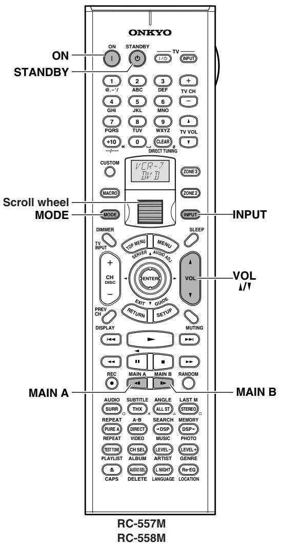
Turning on the Power from the Remote Controller
Before you can use the remote controller, you must perform steps 1 and 2 in the "Turning on the Power" section and place the TX-NR1000/TX-NR5000E in the standby state.
| 1 | Press the scroll wheel. “AMP” appears on the remote controller's display. This is the mode for controlling the TX-NR1000/ TX-NR5000E. |
| 2 | Press the [ON] button to turn on the TX-NR1000/TX-NR5000E. To set the TX-NR1000/TX-NR5000E to Standby, press the [STANDBY] button. |
Operating with Remote Controller
| 1 MAIN A MAIN B | Press the button for the room where you want to play your device. MAIN A: Switches to operations in main room A. MAIN B: Switches to operations in main room B. When MAIN A or MAIN B is selected, the indicator on the front display of the TX-NR1000/TX-NR5000E lights. If the mode is already effective, you do not need to press. If you press this button, the mode is made becomes ineffective. The speaker set in the Speaker/Output Setup menu sounds in the room selected. |
| 2 ↑ | Roll the scroll wheel to select a device to play. Carry out this operation when neither the [MODE] button nor the [INPUT] button lights. If any button lights, press it to turn it off. Rolling the scroll wheel lights both but-tons, and switches the input source and the mode at the same time. |
| 3 | Start playing the device selected. When playing a picture device such as a DVD player, you need to switch the input to a monitor such as TV set. Some picture-playing devices such as a DVD-type game machine may also require setting of sound output. Refer to the manual of the device connected. |
| 4 VOL | Adjust the volume level with the [VOL 1/1] button. You can adjust the volume level in the range from -∞, -81.5 dB to 18.0 dB (Max) (when Relative is selected in the Volume Setup sub-menue). Hint: The TX-NR1000/TX-NR5000E is a product for users to enjoy the home theater, so it is equipped with a wide range of volume levels. Please fine-tune the volume level according to you preferences. |
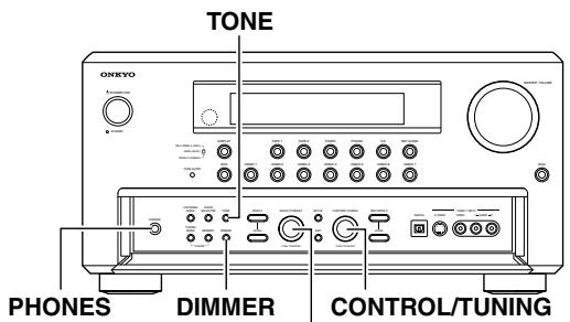
SELECT/PRESET
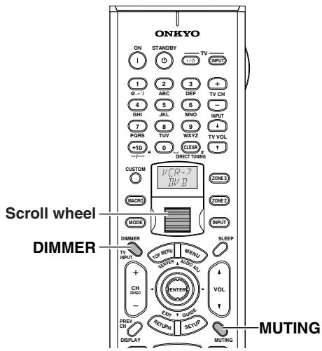
Listening with Headphones
To listen with headphones, plug a pair of headphones with a standard stereo plug into the PHONES jack on the TX-NR1000/TX-NR5000E front panel.
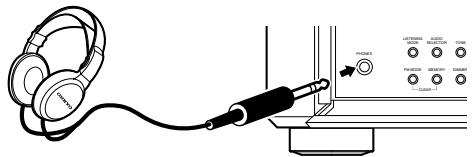
- When you connect headphones, no sound will be heard from the speakers.
While the Dolby Headphone feature is active, appears on the front display.
Refer to pages 58, 59, and 117.
Note:
The signal to the remote zone (Zone 2/3) will not be affected whether or not headphones are connected.
Adjusting the Brightness of the Front Display
You can adjust the brightness of the front display of the TX-NR1000/TX-NR5000E using the [DIMMER] button on the remote controller or on the TX-NR1000/ TX-NR5000E front panel (other than European models).
TX-NR1000/ TX-NR5000E
Use the [DIMMER] button on the TX-NR1000/TX-NR5000E to select: normal, dark, very dark, and volume only.

Remote controller


On the remote controller, press the scroll wheel, and then press the [DIMMER] button.
Temporarily Turning Off the Sound (remote controller only)
Use the [MUTING] button to temporarily turn off the sound immediately.
Remote controller
Press the scroll wheel, and then press the [MUTING] button on the remote controller.


When pressed, "Muting" is displayed on the TX-NR1000/TX-NR5000E. Press the [MUTING] button again to turn the sound back on.
H
Adjust the Tone
You can adjust bass, mid, and treble notes for each speaker set. You can also adjust the tone using the setup menu (see page 118).
1
Press the [TONE] button.
TX-NR1000/ TX-NR5000E

2
Turn the [SELECT/PRESET] dial to select the channel and tone you want to adjust.
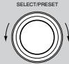
3
Turn the [CONTROL/TUNING] dial to adjust the tone.

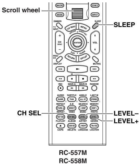
Using the Sleep Timer (remote controller only)
With the sleep timer you can set the TX-NR1000/ TX-NR5000E so that it automatically turns off after a set period.
Remote controller

Press the scroll wheel, and then press the [SLEEP] button repeatedly to select the required sleep time.
You can set the sleep time from 90 to 10 minutes in 10 minute increments.
The [SLEEP] indicator appears on the display when the sleep timer has been set, as shown. The specified sleep time appears on the display for about five seconds, then the previous display reappears.
Note:
If you are using the remote zone (Zone 2 or 3), it will turn off at the same time as the main zone.
$$ S l e e p \quad S d m i n $$
To cancel the sleep timer, press the [SLEEP] button repeatedly until the [SLEEP] indicator disappears.
To check the remaining sleep time, press the [SLEEP] button. Note that if you press the [SLEEP] button while the sleep time is being displayed, you'll shorten the sleep time by 10 minutes.
Temporarily Changing the Speaker Output Levels (remote controller only)
To change the individual speaker volumes temporarily, follow the procedure given below. Each channel can be set between -12 and +12 decibels (between -15 and +12 decibels for the subwoofer). Note that the speaker volumes will return to the original settings when the TX-NR1000/TX-NR5000E is put in the standby state.
1 Press the scroll wheel to enter the AMP mode.
Press the [CH SEL] button and select the desired speaker.
3 Press the [LEVEL -] or [LEVEL +] button to adjust the volume level.
Note:
You cannot select a speaker if it is set to "Not Used" in the Speaker Configuration Sub-menu of the Speaker/ Output Setup Menu.
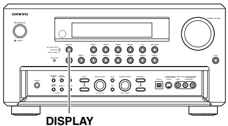
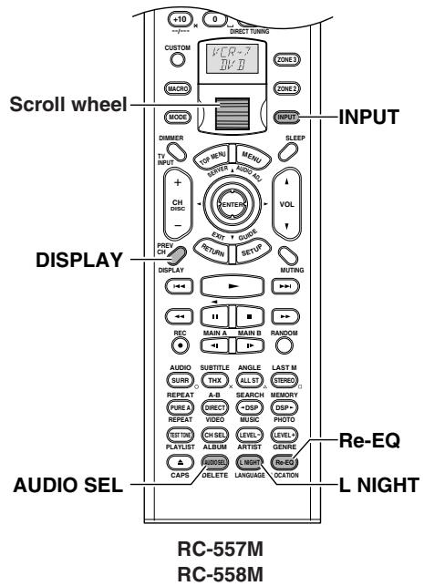
Switching the Display
While listening to or watching an input source, you can display information regarding the type of source and signal being input.

TX-NR1000/ TX-NR5000E

Remote controller


Press the [DISPLAY] button on the TX-NR1000/TX-NR5000E.
On the remote controller, press the scroll wheel, and then press the [DISPLAY] button.
When an input source other than FM or AM is selected:
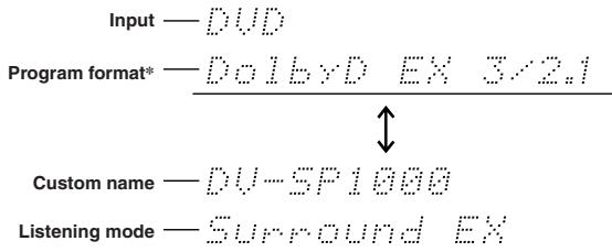
* When the input signal is digital audio other than PCM
The program format is displayed. For example, the display "Dolby D: 3/2.1" shows that the format is Dolby Digital with 5.1 discrete channels consisting of three front channels (front left, front right, and center), two surround channels (surround left and surround right), and the low frequency effect (LFE) channel.
When the front channel number is 2, they are the front left and front right; when it is 1, it is monaural. When the surround channel number is 1, it is monaural; when it is 0, there is no surround channel. When no LFE number is given, there is no LFE channel. Also, if there is no program format for the input signal, nothing will be displayed.
When the input signal is linear PCM
The sampling frequency is displayed. For example, the display "PCM fs: 44.1k" shows that the signal is PCM and that the sampling frequency is 44.1kHz .
Dialog norm
Dialogue Normalization (Dialog Norm) is a feature of Dolby Digital. When playing back software that has been encoded in Dolby Digital, sometimes you may see a brief message in the front panel display that reads Dialog Norm xdB ("x" being a numeric value). Dialogue Normalization serves to let you know if the source material has been recorded at a higher or lower level than usual. For example, if you see the message "Dialog Norm: +4" in the front panel display, to keep the overall output level constant the output volume has been automatically decreased by 4 dB. In other words, the source material that you are listening to has been recorded 4 dB louder than usual.
$$ \text {D i a l o g N o r m} + 4 $$
When FM or AM is selected as the input source:
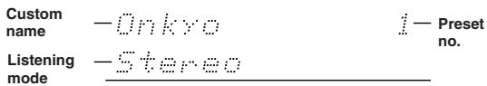
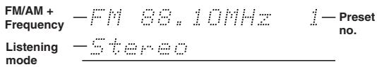
Changing the Audio Mode
The TX-NR1000/TX-NR5000E accepts analog, digital, i.LINK (AUDIO), and multichannel signals for audio input. You can choose the kind of signal to be played for a specific device. For Zone 2, the TX-NR1000/ TX-NR5000E accepts only analog and digital signals for audio input.
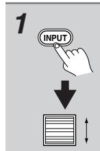
Press the [INPUT] button, and then roll the scroll wheel to select the input source you want to set.
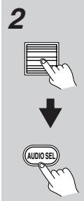
Press the scroll wheel and then press the [AUDIO SEL] button.
Each time the button is pressed, the mode changes from "Auto" "Analog" "Multich" "i.LINK" and back to "Auto." The "Auto" audio mode is recommended for normal circumstances.
Note:
This procedure can also be performed by using the TX-NR1000/TX-NR5000E. Press the [AUDIO SELECTOR] button then use the [SELECT/PRESET] dial to select the mode you want to set.
Auto (XXX) (automatic detection): With this setting, the TX-NR1000/TX-NR5000E automatically detects whether the input signal is digital or analog. When a digital signal is not input, then the analog signal is played. This setting only appears if a digital input is selected for the Digital Input setting at Setup Menu Input Setup Menu Audio Assign Sub-menu Digital Audio (See page 95). (XXX) displays the name of the assigned terminal.
Multich (Multichannel): Select this setting to play back the input from the component connected to the MULTI-CH IN 1/2 port. This setting only appears if "1" or "2" is selected for the Multichannel setting at Setup Menu Input Setup Menu Audio Assign Submenu Multichannel (See page 94).
Analog: Select this setting to playback the input from a source component connected to analog audio input jacks. With this setting, even if a digital signal is input from the same component, only the analog signal will be output.
i.LINK: Select this setting to play back the input from a source component connected to the i.LINK (AUDIO) terminal. With this setting, only the i.LINK signal will be output. This settings is available when any device is selected at Input Setup menu Audio Assign Submenu i.LINK.
Using the Re-EQ Function
This function corrects soundtracks with a strong treble level to the home theater level. This correction should be made when the treble sounds from the front speakers are too strong.
Hint:
This can also be set on the menu with OSD. The listening mode which the Re-EQ effect can be applied to has a Re-EQ option in the Listening Mode Setup menu.
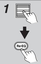
Press the scroll wheel, and then press the [Re-EQ] button (repeatedly).
Using the Late Night Function (only in Dolby Digital)
The difference between loud and quiet sounds is very large in pictures produced for movie theaters, so you have to raise the volume level to catch environmental sounds and human conversations. Since the Late Night Function is able to reduce the difference between loud and quiet sounds, you can hear quiet sounds without raising the entire volume level. This function is helpful when you enjoy movies late at night by turning down sounds.
This function is released when putting the TX-NR1000/ TX-NR5000E into the standby status.
Hint:
This function can also be set on the menu with OSD (See page 106).
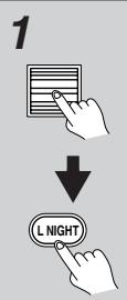
Press the scroll wheel, and then press the [L NIGHT] button (repeatedly).
Off: Turns off the Late Night function.
Low: Reduces the difference between loud and quiet sounds.
High: Further reduces the difference between loud and quiet sounds.
The previous display comes back after a while.
Notes:
- The Late Night function is effective only for Dolby Digital sources.
- The Late Night function may be less effective or have no effect depending on the Dolby Digital source.
Using the Listening Modes
Types of Listening Modes
Listening modes on the TX-NR1000/TX-NR5000E enable you to enjoy movie theater or concert hall quality sounds in your room. The TX-NR1000/ TX-NR5000E provides the following listening modes. Before playing a source in optimal sound, be sure to complete the Speaker/Output Setup (See pages 88 - 91).
Direct
This mode allows you to enjoy pure sounds straight from an original source. Every channel of the audio input source will be output "as is" to respective channels.
Pure Audio
In addition to the Direct mode, playback of music more faithful to the original sounds is enabled because the display window is turned off to minimize noise sources (the power supply to the video circuitry is also turned off, so nothing is displayed on the screen).
Stereo
Sounds are output from the right and left front speakers, and the subwoofer.
Mono
This mode is suitable for playing old movies recorded in monaural sound, or for playing the right and left channels separately on bilingual sources. This mode also allows you to listen to multiplexed soundtracks on DVDs and other sources.
Dolby Pro Logic II
This mode enables 5.1-channel playback of music and movies recorded in 2 channels. You can select the Movie mode, best designed for playing movies, the Music mode, best designed for listening to music, and the Game mode, best suited for enjoying games.
- PLII Movie
This mode can be used with VHS and DVD videos with the DOLBY SURROUND mark, and certain television programs.
- PLII Music
This mode can be used with stereo music CDs and DVD recordings of live concerts.
- PLII Game
This mode can be used with game discs.
Dolby Pro Logic IIx
This mode reproduces in 5.1-7.1 channels music CDs and movies recorded in 2 channels. Together with clearer sounds, you will hear more natural and smoother surround effects than ever before. In addition to CDs and movies, game sources are played with a dramatic spatial presentation and with sound localization. And this mode enables 7.1 channel playback of music and movies recorded in 5.1 channels. You can select the PLIIx Movie and PLIIx Music mode.
- PLIIx Movie
This is the best mode for viewing movies.
- PLIIx Music
This is the best mode for playing music.
- PLIIx Game
This is the best mode for enjoying games, providing the best sense of signal movement.
Dolby Digital
This is a surround mode that will make you feel as if you are sitting in a seat inside a theater or concert hall. This mode can be used with DVDs and LDs with the mark.
Dolby VS (Dolby Virtual Speaker)
The dynamic surround sound effects specific to 5.1 channel speakers are reproduced through 2 speakers. When combined with "Dolby Pro Logic II"/"DTS NEO:6," this mode provides 5.1 channel surround music recorded in 2 channels on CD or MP3 through only 2 speakers. This mode can also be applied to a system equipped with more than 2 speakers. If you are able to use only 2 speakers in a separate room (Zone 2 or Zone 3) or main room B, this mode will let you experience truly powerful sounds of a movie, CD or game through the virtual surround effects. When you use this mode with three or more speakers, the speakers used for output will depend on the input source and decoding mode.
Dolby Digital EX/Dolby EX
This mode enables 6.1 channel playback of music or movies recorded in 5.1 channels. Adding a surround channel to the backside of 5.1 channel speakers to make them 6.1 channel speakers will enhance space expressions that should give you a real feel of moving sounds such as 360-degree rotation or overhead flying. Since sounds on the surround back channel are divided into the surround left and right channels, this mode also enables conventional 5.1 channel playback. When playing DVDs and LDs recorded in 5.1 channels with the
mark, Dolby Digital EX mode turns on, and when playing other sources, Dolby EX turns on.
DTS
Sound data that would be of tremendous size if completely divided into 5.1 channels are compressed into digital data with a status as close as possible to the original sounds. Playing in this mode requires a DVD player able to output DTS. This mode can be used with CDs, DVDs and LDs with the mark.
DTS 96/24
This is a listening mode available with DTS 96/24. This mode allows you to enjoy delicate sounds.
DTS-ES Discrete
This is a 6.1 channel surround system based on DTS with a surround back channel added. Since all 6.1 channels including the added surround back channel are recorded as completely independent digital data, a 3-D feeling and a sense of moving sounds are reproduced more clearly. This mode can be used with CDs, DVDs,
and LDs with the mark.
DTS-ES Matrix
This mode plays in 6.1 channels the music and movies recorded in DTS-ES. Sources recorded in DTS-ES include data for the surround back channel, and each channel is reproduced in 6.1 channels. This mode can be used with CDs, DVDs, and LDs with the dts mark.
DTS NEO:6
This mode enables 6.1 channel playback of music and movies recorded in 2 channels. A broad frequency band is allocated to each channel, and every channel is kept very independent. This mode can be set to the Cinema mode, best designed for playing movies, and the Music mode, best designed for listening to music.
The sources recorded in 5.1 channels are played in NEO:6.
- NEO:6 Cinema
Surround effects full of moving sound feelings are reproduced. This mode is suitable for 2 channel recorded VHS videos, DVD videos, and television programs.
- NEO:6 Music
Since it uses a surround channel, this mode creates a natural sound field, which cannot be expected from ordinary 2 channel output. This mode is suitable for playing CDs recorded in 2 channels.
AAC
Digital data compressed through the MPEG-2 AAC system reproduces surround sounds of 5.1 channels at maximum. This mode can be used for playing AAC sources such as a BS-digital-broadcasted program.
Multiplex
This mode is used for listening to multiplex broadcasts.
THX
This mode produces the maximum effects on a THX-compliant speaker system.
- THX Cinema
This is a 5.1 channel THX mode, designed for viewing theatrical films recorded and edited on the assumption that they will be played in a sizable place like a movie theater. The audio output for the surround back channels depends on the input source and decoding mode.
THX Ultra2 Cinema
This is the THX Ultra 2 mode. This mode enables 7.1 channel playback of music and movies recorded in 5.1 channels. It analyzes surround factors to be reproduced, and distributes the factors to the surround back to optimize the atmosphere and the sense of orientation. This function reinforces the horizontal and backward extension, and the sound location.
- THX Music Mode
This is the THX Ultra 2 mode designed for playing music sources. It enables 7.1 channel playback of 5.1 channel recorded sources.
- THX Games Mode
This is the THX Ultra 2 mode designed for playing game sources.
- THX Surround EX
"THX Surround EX" - Dolby Digital Surround EX is a joint development of Dolby Laboratories and the THX Ltd.
In a movie theater, film soundtracks that have been encoded with Dolby Digital Surround EX technology are able to reproduce an extra surround back channel which has been added during the mixing of the program. A list of Surround EX encoded movies can be found on www.Dolby.com.
- Multichannel
This is a listening mode available with analog multi-channel connection.
i.LINK: DVD-Audio
This is a listening mode used for playing DVD-Audio format sources during i.LINK (AUDIO) connection.
i.LINK: SACD
This is a listening mode used for playing Super Audio CD format sources during i.LINK (AUDIO) connection.
Onkyo's Proprietary Listening Mode (DSP)
All Ch Stereo
This mode is useful for playing music as BGM. Stereo sounds are provided by all speakers, so you can enjoy a powerful sound field.
Full Mono
Monaural sounds are provided by all speakers. You can listen to the same tone of music wherever you are.
Mono Movie
This mode is suitable for playing old movies recoreded in with monaural sound. The center channel outputs straight sounds, while other speakers provide center sounds with adequate echo effects. Despite monaural sound, you can enjoy the feeling of being in a movie theater.
Enhance
This mode is suitable for playig music, and watching sports programs on television. Environmental sounds are move naturally to the surround and surround back speakers, so more dynamic sounds are reproduced.
Orchestra
This mode is suitable for playing classical music and operas. The surround effects are reinforced to extend the sound image throughout the listening room. You can enjoy the natural touch of music as if you are sitting in a large concert hall.
Unplugged
This mode is suitable for listening to acoustic sounds, vocals and jazz music. Because it focuses on the front sound image, this mode creates an image of the sound field that makes you feel as if you are listening to music in front of a stage.
TV Logic
This mode is suitable for television programs broadcast from studios. You may feel as if you are sitting in a television studio. All of the surround sounds are enhanced, and conversations are output clearly.
Listening Modes for Listeners Using Headphones
Dolby Headphone
This mode makes headphones reproduce dynamic surround sound effects like 5.1 channel speakers. The listening mode used before putting on headphones is applied to the headphones. However, the following listening modes will be decoded as follows:
- The Dolby VS or Stereo mode sources will be decoded in the Dolby Headphone mode.
- The source decoded in the 7.1ch surround format will be decoded in the 5.1ch surround format.
- The DTS 96/24 mode source will be decoded in the DTS format.
Listening modes when the Dolby Headphone is set to "Off":
Direct
When the listening mode was Direct before putting on headphones, this mode is applied. Effects are the same as the Direct mode indicated previously.
Pure Audio
When the listening mode was Pure Audio before putting on headphones, this mode is applied. Effects are the same as the Pure Audio indicated previously.
Mono
When the listening mode was Mono, Mono Movie or Full Mono before putting on headphones, this mode is applied. Effects are the same as the Mono mode indicated previously.
This mode is also applied when you listen to the monaural source in the Dolby VS listening mode before putting on headphones.
Stereo
When the listening mode was other than Direct, Pure Audio, Mono, Mono Movie or Full Mono before putting on headphones, this mode is applied. Effects are the same as the Stereo mode indicated previously.
Multiplex
When the listening mode was Multiplex before putting on headphones, this mode is applied.
Selecting the Listening Mode
The TX-NR1000/TX-NR5000E provides various listening modes.
Note:
The available modes depend on the input signal you selected.
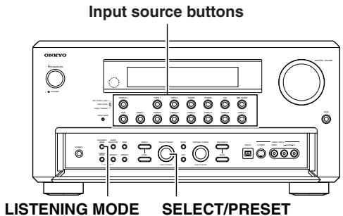
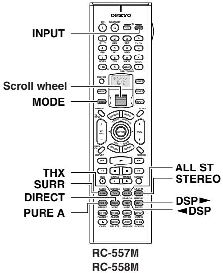
Operating on the TX-NR1000/TX-NR5000E
1 Press the input source button.
2 Start playback on the device you selected for input.
3 Press the [LISTENING MODE] button, and then turn the [SELECT/PRESET] to select a listening mode.
Operating with the Remote Controller
1 Roll the scroll wheel to select a device for playback.
Perform this operation when neither the [MODE] button nor the [INPUT] button lights. If any button lights, press it to turn it off. Rolling the scroll wheel lights both buttons, and switches the input source and the mode at the same time.
2 Start playback on the device you selected for input.
3 Press the scroll wheel, and then press the listening mode button you want to select.
PURE A button: To switch the listening mode to "Pure Audio." When you select "PURE AUDIO," the video signal is interrupted (resulting in a blacked-out screen), and the [PURE AUDIO] indicator lights up.
DIRECT button: To switch the listening mode to "Direct."
STEREO button: To switch the listening mode to "Stereo."
SURR button: To switch the listening mode to the surround mode.
- When 5 channel signals are input, every time you press the button, the listening mode changes "DolbyEX" "PLIIx Movie (Default)" "PLIIx Music" "NEO:6" "Off" "DolbyEX," and so on.
- When 2 channel signals are input, every time you press the button, the listening mode changes "PLIIx Movie (Default)" "PLIIx Music" "PLIIx Game" "NEO:6 Cinema" "NEO:6 Music" "PLIIx Movie (Default)," and so on.
THX button: To switch the listening mode to "THX."
- When Dolby Digital multichannel (^* / 2) signals are input, you can switch to any of the following decode modes. Every time you press the button, the listening mode changes "THX Cinema" "SurroundEX" "Ultra2 Cinema (Default)" "MusicMode" "Games Mode" "THX Cinema," and so on (See page 112).
DSP/DSP buttons: Every time you press the buttons, you can switch to any of the listening modes according to the input signals. ALL ST button: To switch the listening mode to "All Ch Stereo."
[ \left[ \triangleleft \right] / \left[ \triangleright \right] ] cursor buttons:
- When AAC's multiplex sound signals are input, the main-sound and sub-sound are switched. Every time you press the [] / [] buttons, the mode changes "Main" "Sub" "Main + Sub" "Main," and so on.
- When using the headphones, you can use the [] / [] buttons to switch on/off the Dolby Headphone listening mode.
Tip:
A table listed later in this manual shows which listening mode can be used with which input signal format. See page 143.
Listening to Radio Broadcasts
Using the Tuner
One of the features of the TX-NR1000/TX-NR5000E that is most frequently used is its ability to play FM and AM broadcast radio stations. The TX-NR1000/TX-NR5000E provides a number of listening modes perfect for listening to the radio and getting the most out of your audio system. Also, by presetting radio stations that you listen to frequently, you can select them easily by pressing the [CH/DISC + / - ] button on the remote controller.
Setting the AM Tuning Interval
For the Asian or Australian models, you have to adjust the "AM Frequency Step" setting according to your area. Use the Setup menu to adjust the "AM Frequency Step" setting.
To perform this setting, go to "Hardware Setup" "AM Frequency Setup" "Frequency Step," and select "9 kHz" or "10 kHz." For details on this setting, see page 87.
Tuning into a Radio Station
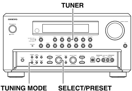
Tuning into a Radio Station Automatically (automatic tuning)

1
Press the [TUNER] input source button.
Each time you press the [TUNER] button, the input source changes between AM and FM.
![ONKYO TX-NR1000 - Press the [TUNER] input source button. - 1](/content/2025/01/151762/images/f28c8e1deb2bf2db801b77e08420cb25eed34a0c5c3543d9dee1f1fa6031f9d0.jpg)
2
Press the [TUNING MODE] button to turn on the "AUTO" indication.
![ONKYO TX-NR1000 - Press the [TUNING MODE] button to turn on the "AUTO" indication. - 1](/content/2025/01/151762/images/8419143e7d1a3ea9d3ef2cda790d1015e6b3e8589c2b58821fe8f152316a89c8.jpg)
3
Turn the [CONTROL/TUNING] dial either clockwise or counterclockwise. This starts tuning automatically.
The tunes stops automatically where it tunes into a station.
When you tune into a radio station,
TUNED indicator appears in the display. If you tune into an FM station in stereo, then "FM STEREO" appears.
FM
Band
88.
Frequency
When the FM stereo broadcast contains much noise: Press the [TUNING MODE] button to switch to the manual tuning mode. The "AUTO" indication disappears and the tuner turns into the monaural mode. In the monaural mode, the noise will be reduced and the broadcast be easier to hear.
Tuning into a Radio Station Manually (manual tuning)

1
Press the [TUNER] input source button.
Each time you press the [TUNER] button, the input source changes between AM and FM.
![ONKYO TX-NR1000 - Press the [TUNER] input source button. - 1](/content/2025/01/151762/images/33e6597e60de772d9c769b6b8e43f88c6ffce0b261155cfec999b999510e8cea.jpg)
2
Press the [TUNING MODE] button to turn off the "AUTO" indication.
![ONKYO TX-NR1000 - Press the [TUNING MODE] button to turn off the "AUTO" indication. - 1](/content/2025/01/151762/images/b6da82b7401dd9d434b726ecdb2248192869a1fa3a292ee7152cbb4a4fd2c48c.jpg)
3
Turn the [CONTROL/TUNING] dial either clockwise or counterclockwise to tune your station.
Turning counterclockwise decreases the frequency, and turning clockwise increases the frequency.
- The tune frequency changes in 200kHz (50 kHz) increments for FM and 10kHz (or 9 kHz) increments for AM.
- When you tune into an FM station manually, the tuner turns into monaural mode. If you want to listen to the FM station in stereo, press the [TUNING MODE] button.
Specifying Radio Stations by Frequency
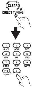
Remote controller
To select a radio station by entering its frequency, press the remote controller's
[DIRECT TUNING] button, and then use the number buttons to enter the frequency.
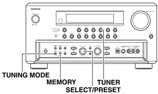
Presetting a Radio Station
Up to 40 stations can be stored in memory as preset radio stations.
| 1 | Tune into the radio station you desire (See “Tuning Into a Radio Station”). |
| 2 | Press the [MEMORY] button on the front panel. Flashes FM 88.1 MHz |
| 3 | Using the [SELECT/PRESET] dial, select a preset number (from 1 to 40) to assign the station. The “MEMORY” indicator blinks for 5 seconds. Complete the procedure while the “MEMORY” indicator blinks. If the “MEMORY” indicator disappears before completing the procedure, go back to step 2 and repeat the procedure again. |
| 4 | Press the [MEMORY] button to finalize the procedure. Lights FM 88.1 MHz |
| You can enter text names for any of the preset radio stations (See page 97). |
Selecting a Preset Radio Station
When using the TX-NR1000/TX-NR5000E:
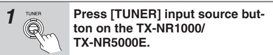
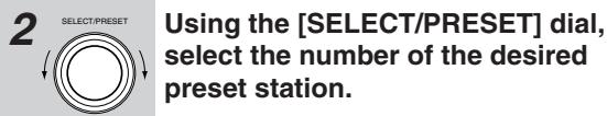
When using the remote controller:
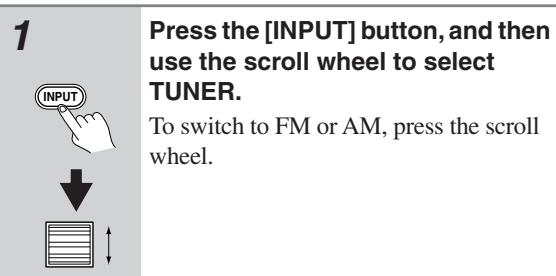
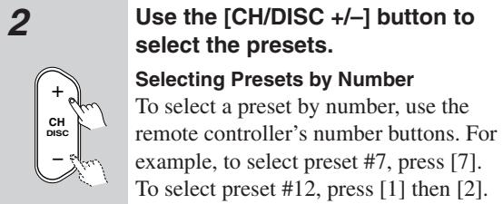
Erasing a Preset Radio Station
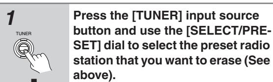
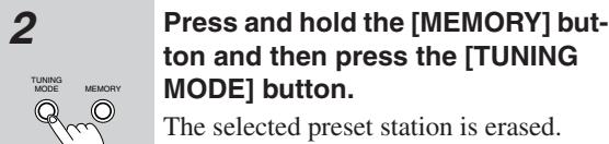
Listening to RDS Broadcasts (European models only)
Listening to RDS Broadcasts
RDS reception is available only on the European model and only in areas where RDS broadcasts are available.
What is RDS?
RDS stands for Radio Data System and is a type of FM broadcasting. RDS was developed within the European Broadcasting Union (EBU) and is available in most European countries. Many FM broadcasting stations now transmit the RDS signals, which provide the additional information required. RDS provides you with various services so that you can choose a station that broadcasts your favorite categories of music, news, or other information.
There are three main classifications of RDS broadcasts. Though they can be tuned into by using the Tuning buttons as normal stations, RDS broadcasts allow you to scan for stations of the type and classification for which you are looking. This makes it much easier for you to find the station you want (See "Performing a PTY Scan" and "Performing a TP Scan" on page 63). The three main classifications are explained below.
RT: Radio Text
When an RDS station broadcasting RT information is selected, the text information received from the station is displayed.
PTY: Program Type
When an RDS station broadcasting PTY information is selected, the station type (classification) is displayed.
TP: Traffic Program
When an RDS station broadcasting TP information is selected, traffic information will be broadcast periodically.
Notes:
- In some cases, the characters displayed on the display of the TX-NR5000E may not be exactly the same as the ones broadcast by the radio station. Also, unusual characters may appear on the display if the TX-NR5000E receives characters that cannot be displayed correctly. This is not a malfunction.
- When an RDS station broadcasting PS information is selected, the name of the station is displayed instead of the frequency.
PTY Program Types in Europe
The text given in parentheses is what is actually displayed on the TX-NR5000E.
None (NONE):
No program type.
News reports (NEWS):
Reports on current events and happenings.
Current affairs (AFFAIRS):
Topical reporting of current affairs, often with a wider range of topics than news reports.
Information (INFO):
General information such as weather forecasts, consumer affairs, medical help, etc.
Sports (SPORT):
Live sports action, sports news, and interviews.
Education (EDUCATE):
Formal educational programs.
Drama (DRAMA):
Radio plays and serials.
Culture (CULTURE):
Cultural programs (including religious affairs).
Science and technology (SCIENCE):
Programs about the natural sciences and technology.
Varied (VARIED):
Speech-based programs not covered by the above categories (e.g., quizzes, panel games, and comedy).
Pop music (POP M):
Popular commercial music, usually from past or present sales charts (e.g., Top 40).
Rock music (ROCK M):
Popular music with an alternative appeal, often not appearing on sales charts.
Middle of the road music (M.O.R. M):
Easy listening music (as opposed to Pop, Rock, or Classical).
Light classics (LIGHT M):
Classical music for general rather than specialist appreciation.
Serious classics (CLASSICS):
Performances of major orchestral works, symphonies, chamber music, etc. (including Grand Opera).
Other music (OTHER M):
Music styles not covered by the above categories (e.g., Jazz, Rhythm & Blues, Folk, Country, and Reggae).
- Alarm (ALARM):
When an RDS station is making an emergency broadcast, this ALARM will flash on the display.
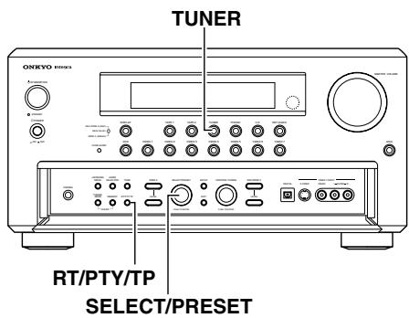
Displaying Radio Text (RT)
If the station you are currently tuned into is broadcasting RT signals, they will be displayed in the front display on the TX-NR5000E. If the station does not, this function will be ignored.

To display the radio text, press the [RT/PTY/TP] button once.
- If the current station you are listening to is not an RDS station, only the frequency of the station will appear.
- If "Waiting" appears on the display, more time is required to receive the RT information. When the information is received, the characters will scroll across the front display.
- If "No Text Data" appears on the display, RT information is not available.
- The display shows the frequency for 3 seconds and returns to program service name.
Performing a PTY Scan
Press the [TUNER] input source button and select the FM input source.

Press the [RT/PTY/TP] button twice.
The current program type appears on the display.
RIOCK
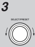
Using the [SELECT/PRESET] dial, select the PTY program type you desire.
LIGHTM
4
Press the [SELECT/PRESET] dial.
The TX-NR5000E will scan until it reaches a station of the program type you selected. It will then stop briefly at that station before continuing on until it reaches the next station. Pressing the [SELECT/PRESET] dial stops the PTY scan at that point. If you press the [RT/PTY/TP] while "NONE" is displayed, "PTY ?" will appear. In this case, return to step 3.
5
Press the [SELECT/PRESET] dial when it reaches the station that you want to listen to.
"Not Found" will appear when no RDS signal is being received from the station.
Performing a TP Scan

1
Press the [TUNER] input source button.

2
Press the [RT/PTY/TP] button three times.
PP
"[TP]" will appear if the current station is broadcasting TP signals. This station will periodically broadcast traffic information. To find a different station, proceed to the next step. Also, if "TP" is displayed, proceed to the next step.
3
Press the [SELECT/PRESET] dial.
The TX-NR5000E will scan until it reaches a station broadcasting traffic information. If "Not Found" appears on the display, a TP station cannot be located.
Enjoying Multichannel Playback
To the TX-NR1000/TX-NR5000E, you can be connected up to two devices, such as a DVD player, that deal with multichannel sounds (5.1-7.1 channels). To use multichannel connections, you need to specify settings on the Input Setup menu. In addition, you can set listening modes as you prefer. Enjoy multichannel playback in the main room.
How to Connect
Use three or four multichannel connection cables or audio connection cables to connect the multichannel output jack on the connected device to the MULTI-CH IN 1/2 jack on the TX-NR1000/TX-NR5000E.
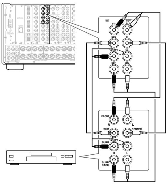
How to Set Up
Specify the input source type. At default, DVD is "1," CD is "2," and others are "No."
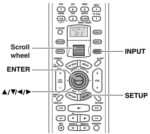
1 Press the [INPUT] button, and then roll the scroll wheel to select the input source to be set.
2 Press the scroll wheel, and then press the [SETUP] button to display the Main menu.
3 Press the [ ] / [ ] buttons to select "Input Setup," and then press the [ENTER] button.
4 Press the [ /[ ] buttons to select "Audio Assign," and then press the [ENTER] button.
5 Press the [] / [] buttons to select "Multichannel," and then select a setting with the [] / [] buttons. Select "1" when connected to MULTI-CH IN 1, or "2" when connected to MULTI-CH IN 2.
6 Press the [SETUP] button. Setting is completed, and the menu screen disappears.
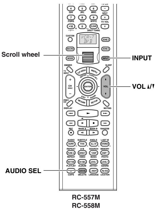
Playing Back in Multichannel Sound
1 Press the [INPUT] button, and then roll the scroll wheel to select the input source to be set.
2 Press the scroll wheel, and then press (repeatedly) the [AUDIO SEL] button to select "Multich."
3 Start playing.
4 Adjust the volume level with the [VOL 1/1 ] buttons.
You can adjust the volume level in the range from -, -81.5 dB to 18.0 dB (when Relative is set for Volume Setup).
Hint:
You can also adjust the volume level with the input source button, the [AUDIO SELECTOR] button, and the [MASTER VOLUME] dial on the TX-NR1000/TX-NR5000E.
You can also set the listening mode in advance for multichannel playback (Listening Mode Preset). To do so, select "Input Setup" "Listening Mode Preset" "Multichannel" on the Setup menu to choose the preferred mode. This defaults to "Multichannel." See page 57 for details of the listening mode, and page 97 for the listening mode preset.
To configure the listening mode settings including audio effect and playback options:
You can specify detailed settings for the decode mode and the speaker environment for multichannel playback (Listening Mode Setup). See page 102 for details.
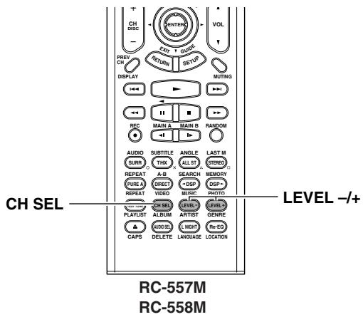
Adjusting the Volume Level of Speakers for Multichannel Playback
Press the scroll wheel, and then press the [CH SEL] button to select a speaker whose volume level you want to adjust.
Speakers set by the Speaker Configuration submenu on the Speaker/Output Setup menu are displayed on a one-by-one basis.
2 Press the [LEVEL - / + ] button to adjust the volume level.
You can adjust in the range from -12dB to +12 dB. The subwoofer can be adjusted in the range from -15dB to +12dB .
Hint:
The volume level of each speaker for multichannel sounds is different from the calibration level to be set with the test sound described on page 90. Adjustment made here is not reflected in playing other than the multichannel playback.
Enjoying Movies and Music in the Remote Zone (Zone 2/3)
You can connect speakers and amplifiers for the remote zone, and enjoy different sources in a remote zone (Zone 2 or Zone 3).
There are three ways to enjoy in a remote zone:
Connecting and Setup
When Connecting Only Speakers (Zone 2)
- You can enjoy a different source in a remote zone while a 5.1 channel source is being played in the main room.
- Adjust the volume level on the TX-NR1000/ TX-NR5000E.
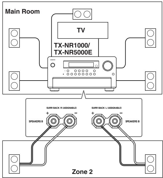
1
Connect the speakers for Zone 2 to SURR BACK L/R SPEAKERS B terminals.
2
Connect the video component for Zone 2 to any of the composite VIDEO OUT 1-4 terminals.
3
Set the Setup menu.
- On the Setup menu (See page 88), select "Speaker/Output Setup" "Speaker Configuration," and set "Speaker B Surr Bk" to "Powered Zone 2."
- Similarly, select "Speaker/Output Setup" "Video Output Assign," and set the terminal connected to the component to "Zone 2 Out."
- Press the [SETUP] button to close the menu.
When Connecting the Pre-main Amplifier or Receiver (Zone 2 or Zone 3)
- You can enjoy a different source in a remote zone while a 7.1 channel source is being played in the main room.
- Adjust the volume level on the pre-main amplifier or receiver in the remote zone.
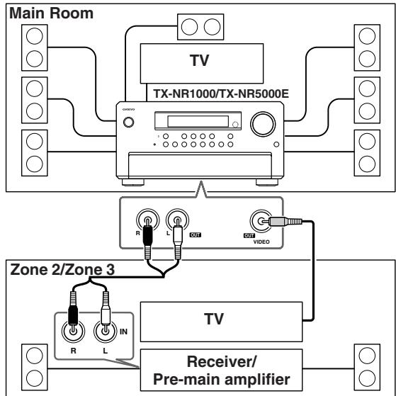
1
Connect the pre-main amplifier or receiver for Zone 2 or Zone 3 to the TX-NR1000/TX-NR5000E.
Connect to any of the following terminals:
AUDIO OUT 1-5
Default:
Analog 4 (AUDIO OUT 4): Zone 2 Out
Analog 5 (AUDIO OUT 5): Zone 3 Out
DIGITAL OUT OPTICAL 1-2
DIGITAL OUT COAXIAL 1-2
2
Connect the speakers for Zone 2 or Zone 3 to the pre-main amplifier or receiver.
3
Connect the video component for Zone 2 or Zone 3 to any of the composite VIDEO OUT 1-4 terminals.
4
Set the Setup menu.
- On the Setup menu (See page 91), select "Speaker/Output Setup" "Audio Output Assign," and set the terminal to which the component is connected to "Zone 2 Out" or "Zone 3 Out."
- Then, set "Zone 2 Out" or "Zone 3 Out" in the Audio Output Assign sub-menu to "Line Out (fixed)."
- Similarly, select "Speaker/Output Setup" "Video Output Assign," and set the terminal to which the component is connected to "Zone 2 Out" or "Zone 3 Out."
- Press the [SETUP] button to close the menu.
When Connecting the Power Amplifier (Zone 2 or Zone 3)
- You can enjoy a different source in a remote zone while a 7.1 channel source is being played in the main room.
- Adjust the volume level on the TX-NR1000/ TX-NR5000E (not on the power amplifier).
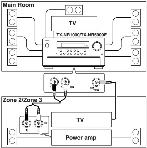
1 Connect the power amplifier for Zone 2 or Zone 3 to the TX-NR1000/TX-NR5000E.
Connect to any of the following terminals:
AUDIO OUT 1-5
- DIGITAL OUT OPTICAL 1-2
DIGITAL OUT COAXIAL 1-2
2 Connect the speakers for Zone 2 or Zone 3 to the power amplifier.
3 Connect the video component for Zone 2 or Zone 3 to any of the composite VIDEO OUT 1-4 terminals.
4 Set the Setup menu.
- On the Setup menu (See page 91), select "Speaker/Output Setup" "Audio Output Assign," and set the terminal to which the component is connected to "Zone 2 Out" or "Zone 3 Out."
- Then, set "Zone 2 Out" or "Zone 3 Out" in the Audio Output Assign sub-menu to "Pre Out (variable)."
- Similarly, select "Speaker/Output Setup" "Video Output Assign," and set the terminal to which the component is connected to "Zone 2 Out" or "Zone 3 Out."
- Press the [SETUP] button to close the menu.
Enjoying Movies and Music in a Remote Zone
- The sleep timer in the main room also works in Zone 2 and Zone 3. To make the sleep timer effective only in Zone 2 or Zone 3, set the sleep timer on the TX-NR1000/TX-NR5000E in the main room, and then put it into the standby status.
- When "Speaker B Surr Back" is set to "Powered Zone 2" on the Speaker Configuration sub-menu of the Speaker/Output Setup menu, 7.1 channel playback is disabled in the main room.
- Sounds and pictures that can be output to Zone 2 and Zone 3 are as follows:
| From Input Terminal | ZONE 2 | REC/ ZONE 3 | To Output Terminal | |
| Audio Input | i.LINK (AUDIO) | ✓ | ✓+1 | AUDIO OUT 1-5 |
| ✓+2 | ✓+2 | DIGITAL OUT OPTICAL 1-2 | ||
| ✓+2 | ✓+2 | DIGITAL OUT COAXIAL 1-2 | ||
| ETHERNET, PH, AUDIO IN 1-9 | ✓ | ✓ | AUDIO OUT 1-5 | |
| DIGITAL OUT OPTICAL 1-2 | ||||
| DIGITAL OUT COAXIAL 1-2 | ||||
| DIGITAL IN OPTICAL 1-6, DIGITAL IN COAXIAL 1-6 | ✓+3 | ✓+1 | AUDIO OUT 1-5 | |
| ✓ | ✓ | DIGITAL OUT OPTICAL 1-2 | ||
| ✓ | ✓ | DIGITAL OUT COAXIAL 1-2 | ||
| Video Input | VIDEO IN 1-6, S VIDEO IN 1-6, COMPO- NENT VIDEO IN 1-6 | ✓ | ✓ | VIDEO OUT 1-4 |
| S VIDEO OUT 1-4 | ||||
| COMPONENT VIDEO OUT |
1 Only PCM output
2 Super Audio CD and DVD-Audio are not output.
*3 Possible for 2 channel downmix signal.
Columns covered by "\" indicate that no setting related to the column is specified for Zone 2 Out or Zone 3 Out in "Audio Output Assign" or "Video Output Assign."
Operating with the Remote Controller
When operating with the remote controller, how to operate depends on the location of Zone 2 or Zone 3, or the distance from the TX-NR1000/TX-NR5000E.
- Point the remote controller at the infrared receiver on the TX-NR1000/TX-NR5000E, and then operate the controller.
- Install a remote controller sensor in Zone 2 or Zone 3 through an IR connection (See page 45).
- Switch the Transmission Signal Format to RF (Radio Frequency) (depending on the destination) (See page 141).
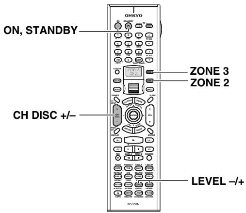
1 Power on the devices in Zone 2 or Zone 3.
Press the [ZONE 2] or [ZONE 3] button, and then the [ON] button.
2 Select a source.
Rotate the scroll wheel to select a source while the [ZONE 2] or [ZONE 3] button is lighted (if the button is not lighted, press the [ZONE2] or [ZONE 3] button to light it).
- When you have selected the tuner, you can choose a preset channel with the [CH DISC +/-] button.
3 Adjust the volume level.
Press the [ZONE 2] (or [ZONE 3]) button, and within 5 seconds, press the [LEVEL - / + ] button to adjust the volume level.
Notes:
- When the pre-main amplifier or receiver is connected, the volume level should be adjusted at the connected component side.
- When not using Zone 2 or Zone 3, press the [ZONE 2] (or [ZONE 3]) button, and then press the [STANDBY] button.
Operating on the TX-NR1000/TX-NR5000E
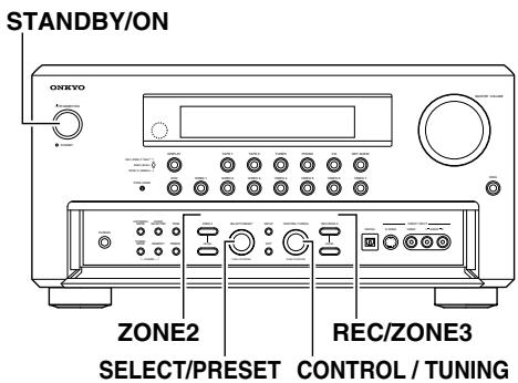
1 Turn on the power supply to the TX-NR1000/TX-NR5000E, and then select a source for Zone 2 or Zone 3.
For Zone 2, press the [ZONE 2] button, and then select the source with the [SELECT/PRESET] dial. For Zone 3, press the [REC/ZONE 3] button, and then, select the source with the [CONTROL/TUNING] dial.
When you press the [ZONE 2] or [REC/ZONE 3] button, the [STANDBY] indicator on the TX-NR1000/TX-NR5000E blinks for five seconds, so perform operations while it is blinking. The source button for Zone 2 lights in green and the source button for Zone 3 lights in red.
To switch the source for Zone 2 (or Zone 3) and the main room simultaneously:
Repeatedly press the [ZONE 2] (or [REC/ZONE 3]) button to display "Z2Sel:SOURCE," and then select the source.
2 Adjust the volume level.
For Zone 2, press the [LEVEL] button under the [ZONE 2] button, and then adjust with the [SELECT/PRESET] dial.
For Zone 3, press the [LEVEL] button under the [REC/ZONE 3] button, and then adjust with the [CONTROL/TUNING] dial.
Notes:
- When a pre-main amplifier or receiver is connected to the TX-NR1000/TX-NR5000E, the volume level should be adjusted at the connected component side.
Enjoying Movies and Music in the Remote Zone (Zone 2/3)—
Continued
- When not using Zone 2 or Zone 3, press the [ZONE 2] (or [REC/ZONE 3]) button, and then press the [STANDBY/ON] button. Or press the [ZONE 2] (or [REC/ZONE 3]) button, and then turn the [SELECT/PRESET] dial to select "Off." In the case of Zone 2, the green indicator on the input source button is turned off, and in the case of Zone 3, the red indicator is turned off.
- When operating in the main room, be sure to confirm that the [STANDBY] indicator is not blinking, and then start operations. When not using in the main room, press the [STANDBY/ON] button. If the TX-NR1000/TX-NR5000E is in the standby status, the power supply to Zone 2 and Zone 3 is not switched off.
Recording a Source
The TX-NR1000/TX-NR5000E can not only record the playing source but can also record a source while playing another source. You can also combine a video and audio to create a new source.
Signals that can be output to a video/audio recording device vary with the type of jack connected. Check the following conditions before starting recording:
Audio
- Signals (analog) from the ETHERNET, PH, or AUDIO IN jacks are output only to the AUDIO OUT jacks. Music signals of MP3, WMA, and WAVE to be played with Net-Audio are also output only to analog audio output jacks.
- No signal is output from the MULTI-CH IN jacks.
- No signal is output from the HDMI IN jacks. Recording via the HDMI OUT jack is also disabled because Rec Out is not available in Audio Output Assign.
- Signals from the DIGITAL IN OPTICAL or COAXIAL jacks are output to the DIGITAL OUT OPTICAL or COAXIAL jacks. PCM signals are converted into analog signals, and also output to the AUDIO OUT jacks.
- Only PCM signals are output from the i.LINK (AUDIO) terminals to the AUDIO OUT jacks. Digital signals are output from the i.LINK (AUDIO) terminals to the DIGITAL OUT OPTICAL or COAXIAL jacks, but signals on Super Audio CD and DVD-Audio are not output.
Video
Video signals from the VIDEO IN, SVIDEO IN, or COMPONENTVIDEO IN jack are output only to theVIDEO OUT jacks.
Some steps can also be operated on the remote controller, but described here are operations on the TX-NR1000/TX-NR5000E.
Notes:
- No surround effects can be recorded.
- No DVD or any sources whose copyright is protected can be recorded.
- There are some restrictions on recording of digital audio/video signals. Refer to the manual of your recording component.
- If recorded as analog signals, DTS signals are recorded as noise, so never record signals from a DTS-compatible CD or LD.
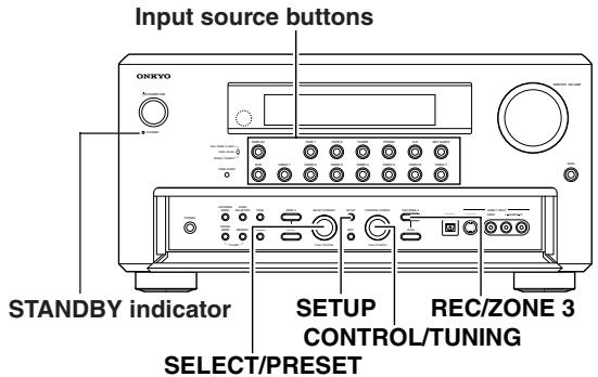
Recording Audio/Video While Playing
Recording music or a movie you are currently playing.
Operate on the TX-NR1000/TX-NR5000E in the main room.
1 Turn on the power supply to TX-NR1000/ TX-NR5000E.
2 Check the connection to your recording component.
An audio recorder should be connected to the AUDIO OUT or DIGITAL OUT jacks, and a video recorder to the VIDEO OUT jacks.
3 Check settings for a recorder connected.
- On the Setup menu (See page 91), select "Speaker/Output Setup" "Audio Output Assign," and specify "Rec Out" as the setting for the jack to which your audio recording component is connected.
- Similarly, select "Speaker/Output Setup" "Video Output Assign," and specify "Video XX Rec Out" as the setting for the jack to which your video recording component is connected.
- Press the [SETUP] button to close the menu. Hint:
Since Zone 3 Out and Rec Out use the same circuitry, audio recording is disabled if Zone 3 Out is specified. Audio/video recording is also disabled on the same component as that for playing.
4 Press the input source button to select the component for audio/video recording (player side).
5 Press the [REC/ZONE 3] button, and within 3 seconds, select "Rec Sel: SOURCE" with the [CONTROL/TUNING] dial.
Pressing the [REC/ZONE 3] button makes the [STANDBY] indicator blink for 3 seconds.
Select the target source while the indicator is blinking. The name of the source to be recorded is indicated in the display window, and the button for the source selected lights in red.
Audio/video recording is enabled on the component for which "Rec Out" was specified in step 3.
6 Prepare the component for audio/video recording (recorder side).
- Put the component for audio/video recording into the recording standby status.
- You should adjust the recording level on the recording component.
- For how to record, refer to the manual of the recoding component.
7 Start audio/video recording
Play the component selected in step 4.
- Switching the source during audio/video recording will record the source newly selected.
- If you select FM (or AM) with the [TUNER] input source button when the recording source is set to AM (or FM), the output for the recording source also changes to AM (or FM).
Recording Audio/Video on a Component While Playing Another
You can record an audio source or a video on a component while playing another source on another component. For example, you can record a CD while watching a DVD. Operate this function on the TX-NR1000/ TX-NR5000E in the main room.
1 Turn on the power supply to TX-NR1000/ TX-NR5000E in MAIN A or MAIN B mode.
Proceeding to the next step in the Standby status makes the Zone 3 mode effective, so be sure to turn on the power source.
2 Check connections and settings to the recording component.
Refer to steps 2 and 3 in "Recording Audio/ Video While Playing" in the previous section.
3 Press the [REC/ZONE3] button, and within 3 seconds, select "Rec Sel:SOURCE" with the [CONTROL/TUNING] dial.
Pressing the [REC/ZONE 3] button makes the [STANDBY] indicator blink for 3 seconds.
Select the target sources while the indicator is blinking. The name of the source to be recorded is indicated in the display window. Audio/video recording is enabled on the component for which "Rec Out" was specified in step 2.
4 Prepare the component for audio/video recording (recorder side).
5 Start audio/video recording.
You cannot listen to a broadcast from one station while recording a broadcast from another station.
Recording the Video from One Source and the Audio from Another Source
You can add audio signals from a source to a video of another source to make your own custom video recordings. Below is an example of recording audio signals from a CD player connected to the DIGITAL IN OPTICAL 2 jack and the video from a video camera connected to VIDEO IN 3 onto a video cassette tape on a VCR connected to VIDEO OUT 2.
Operate this function in the main room.
6 Turn the [SELECT/PRESET] dial to select "Composite Video," and set it to "3" with the [CONTROL/TUNING] dial.
After setting to "3," press the [SETUP] button.
7 Insert a CD in the CD player and insert a tape in the video camera connected to the VIDEO IN 3 jacks.
8 Insert a tape in the VCR connected to the VIDEO OUT 2 jacks.
9 Press the [REC/ZONE 3] button, and within 8 seconds, select "Rec Sel:SOURCE" with the [CONTROL/TUNING] dial.
Now, the CD player has been selected as the audio input source, and VIDEO 3 as the video input source.
10 Start recording on the VCR, and start playing on the CD player and the video camera.
Playback starts on the component selected in steps 3-6.
Note:
Switching the source during audio/video recording will record the source newly selected.
1 Turn on the power supply to the TX-NR1000/TX-NR5000E in MAIN A or MAIN B mode.
2 Check connections and settings to the recording component.
Refer to steps 2 and 3 in "Recording Audio/Video While Playing" on page 70.
3 Press the [CD] input source button.
4 Press the [SETUP] button to display Main menu, and turn the [SELECT/PRESET] dial to select "Input Setup."
After selecting "Input Setup," press the [ENTER] button.
To carry out steps 3-6 on the remote controller, follow the procedures described on page 95.
5 Turn the [SELECT/PRESET] dial to select "Video Setup," and press the [ENTER] button.
Enjoying Net Audio
About Net-Tune
A Net-Tune server is a computer server running NetTune system protocol, including a Net-Tune-compatible home server or a PC with Net-Tune Central installed. The TX-NR1000/TX-NR5000E can be used as a NetTune client on a standard Ethernet network. By installing Onkyo's Net-Tune Central server software on your computer, you can play all of your MP3, WMA, and WAV files through the TX-NR1000/TX-NR5000E. If your network is connected to the Internet, you can also tune into Internet radio stations.
Internet Radio
With Internet radio you can:
- Listen to stations that use MP3 or WMA format streaming.
- Select stations by genre, location, or language.
- Preset up to 30 Internet radio stations.
Net-Tune
For audio delivery over Ethernet, Onkyo developed NTSP (Net-Tune System Protocol). Since it's based on the industry standard TCP/IP protocol, it's efficient and very responsive.
You can download Onkyo's Net-Tune Central server software from the following Onkyo Web sites:
- America: http://www.onkyousa.com/net-tune/
- Europe: http://www.onkyo.net/net-tune/
Japan: http://www.onkyo.com.jp/ - Asia, Oceania, and Latin America: http://www.onkyo-intl.com/
Net-Tune Central searches your PC's hard disk for music files and automatically creates a music database, making it very easy to set up. Net-Tune clients, including the TX-NR1000/TX-NR5000E, can then play music in the database.
Net-Tune Central supports the following file formats, and sampling rates of 32kHz 44.1kHz and 48kHz
WAV: high quality, uncompressed, linear PCM.
- MP3: high quality, compressed, small file size.
- WMA: high quality, compressed, smaller file size than MP3, developed by Microsoft (Protected WMA files cannot be played).
Before you download Net-Tune Central, you'll be prompted to enter the serial number printed on the rear of your TX-NR1000/TX-NR5000E. Depending on your Internet connection, it may take 10 or more minutes to download.
Net-Tune Central Editing Functions
With Net-Tune Central you can edit the titles, album, and artist names of your MP3, WMA, and WAV files, and create and edit genre names. In addition, you can make playlists of your favorite tracks.
Computer Requirements
The computer requirements necessary for running the Net-Tune Central server software are as follows:
- Operating system: Windows XP or 2000 (Mac OS not supported).
- Processor: Intel Pentium III, 600 MHz or higher
- Memory: 128 MB (Windows 2000) 256 MB (Windows XP)
- Display: 800 × 600 pixels or higher,High Color
- LAN/Ethernet network port
Sound capabilities - Hard disk: At least 20 MB for Net-Tune Central. Obviously you'll also need space to store your music files. MP3 and WMA uses approximately 1 MB per minute, while WAV uses approximately 10 MB per minute, although this will depend on the sampling rate and bit rate that you use. MP3 files made using certain encoders may not be playable, or may be noisy when played.
Network Requirements
■ Ethernet Network
The TX-NR1000/TX-NR5000E's Ethernet port supports 10Base-T. For best results, a 100Base-T switched Ethernet network is recommended. Although it's theoretically possible to use a wireless network, due to unpredictable performance, it may not provide satisfactory results, so a wired network is recommended.
Ethernet Router
A router manages the network, routing data and supplying IP addresses. Your router must support the following:
- NAT (Network Address Translation) NAT allows several networked computers to access the Internet simultaneously via a single Internet connection. The TX-NR1000/TX-NR5000E needs Internet access for Internet radio.
- DHCP (Dynamic Host Configuration Protocol) DHCP supplies IP address information to network devices, allowing them to configure themselves automatically.
- A router with a 100Base-TX switch built-in is recommended.
Some routers have a modem built-in, and some ISPs require you to use specific routers. Please consult your ISP or computer dealer if you're unsure.
CAT5 Ethernet cable
Use a standard CAT5 Ethernet cable (straight type).
Internet Access (for Internet radio)
To use Internet radio, your Ethernet network must have Internet access. A narrowband Internet connection (e.g., 56K modem, ISDN) will not provide satisfactory results, so a broadband connection is strongly recommended (e.g., cable modem, xDSL modem, etc.). Please consult your ISP or computer dealer if you're unsure.
Notes:
To use Internet radio with the TX-NR1000/ TX-NR5000E, your broadband Internet connection needs to be up and running and able to access the Web. Please consult your ISP if you have any problems with your Internet connection.
- The TX-NR1000/TX-NR5000E uses DHCP and AutoIP to configure its network settings automatically. If you want to configure these settings manually, see page 121.
- The TX-NR1000/TX-NR5000E does not support PPPoE settings, so if you have a PPPoE-type Internet connection, you must use a PPPoE compatible router.
- Depending on your ISP, you may need to specify a proxy server to use Internet radio. If your PC is configured to use a proxy server, use the same settings (See page 121).
Networking Your TX-NR1000/TX-NR5000E
To connect the TX-NR1000/TX-NR5000E to your Ethernet network, plug one end of a CAT5 Ethernet cable into the ETHERNET (Net-Tune) port, and plug the other end into a LAN port on your router or switch.
The following diagram shows how you can connect the TX-NR1000/TX-NR5000E to your Ethernet network. Here it is connected to a LAN port on the router, which has a 4-port 100Base-TX switch built-in.
You can connect any number of TX-NR1000/TX-NR5000Es to the network, and Net-Tune Central can serve up to three clients simultaneously, so you can enjoy Net-Tune in three separate rooms simultaneously. The following diagram shows a Net-Tune network with two TX-NR1000/TX-NR5000Es.
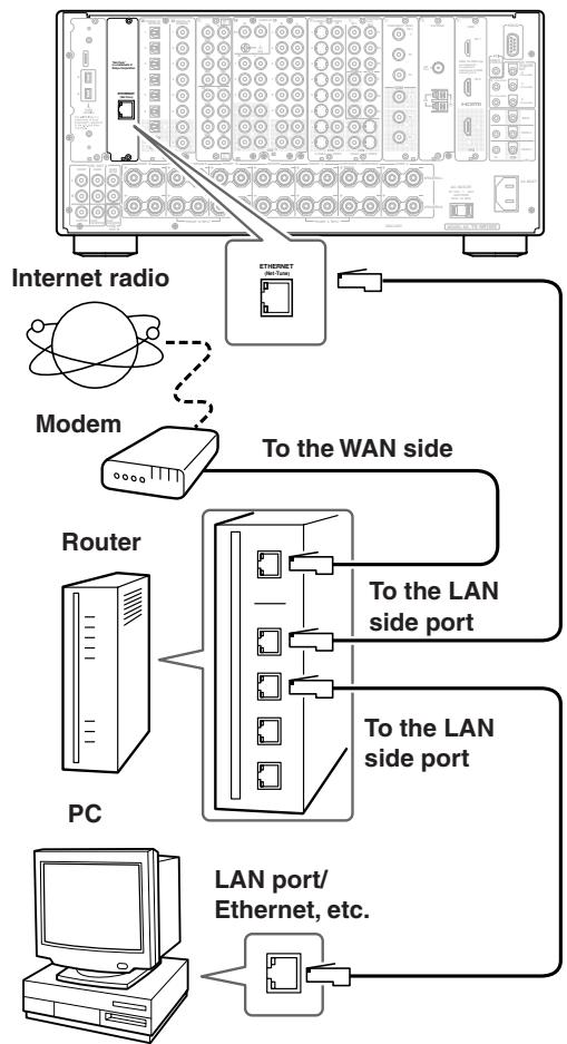
TX-NR1000/TX-NR5000E
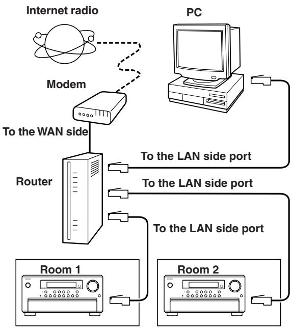
You can install Net-Tune central on several networked computers and use the TX-NR1000/TX-NR5000E's Select Server setting to select the server whose music database you want to access (See page 95).
About Network Configuration
When you use a broadband router with the DHCP function enabled, the network settings will be configured automatically. In this case, you do not have to make any settings using the setup menu. If you disabled the DHCP function on the broadband router, configure the network settings manually referring to page 121.
Using the Remote Controller
To select Net-Tune mode, press the [MODE] button, and then roll the scroll wheel until "NET-T" appears on the display.
Note:
While neither the [INPUT] button nor [MODE] button is illuminated, the scroll wheel changes the input source and remote controller mode simultaneously (when you enter the Net-Tune mode, be sure that the LCD display shows "MSRV" or "IRD" in the top line and "NET-T" in the bottom line).
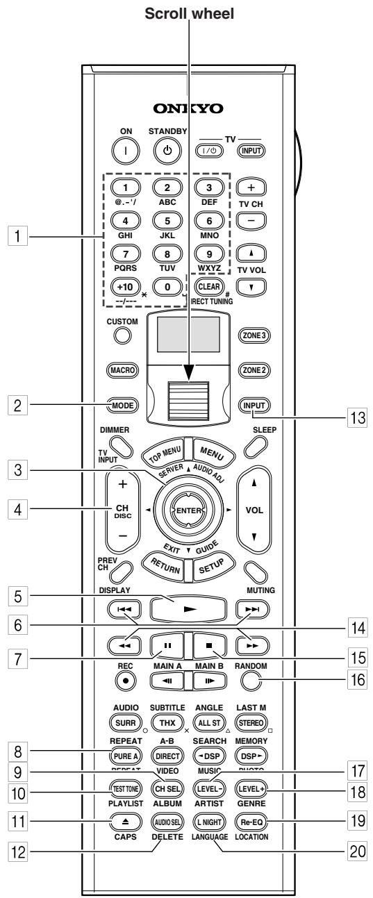
RC-557M
RC-558M
1 Number/letter buttons
These buttons are used to enter numbers and letters when searching for music in your Net-Tune server.
2 MODE button
This button is used with the scroll wheel to select the remote controller modes. Press this button first, and then roll the scroll wheel until "NET-T" appears on the display.
Up/Down/Left/Right ▲/▼/▲/▶ & ENTER buttons
These buttons are used to navigate Internet radio and Net-Tune server menus. The [ENTER] button is used to confirm items and to start playback of the Net-Tune server.
4 CH/DISC +/- button
This button is used to select Internet radio presets.
5 Play button
This button is used to start playback of the Net-Tune server.
Previous/Next / buttons
The Previous button is used to select the previous track. During playback it selects the beginning of the current track. The Next button is used to select the next track.
7 Pause button
This button is used to pause playback.
8 REPEAT button
This button is used for repeat playback.
9 ALBUM button
This button is used to search the Net-Tune server's music library by album.
10 PLAYLIST button
This button is used to search the Net-Tune server's library by playlist.
CAPS button
This button is used to select lowercase letters, uppercase letters, and numbers when searching for the Net-Tune server's music by album, artist, or playlist.
12 DELETE button
This button is used to delete characters entered with the number/letter buttons.
13 INPUT button
This button is used to select the input source. Press this button first, and then roll the scroll wheel until "MSRV" (Music Server) or "IRD" (Internet Radio) appears on the display.
14 FR/FF /> buttons
The FR button is used to start fast reverse. The FF button is used to start fast forward.
15 Stop button
This button is used to stop playback.
16 RANDOM button
This button is used for random playback.
17 ARTIST button
This button is used to search the Net-Tune server's music library by artist.
18 GENRE button
This button is used to search the Net-Tune server's music library by genre, and to search for Internet radio stations by genre.
19 LOCATION button
This button is used to search for Internet radio stations by country.
20 LANGUAGE button
This button is used to search for Internet radio stations by language.
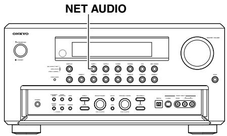
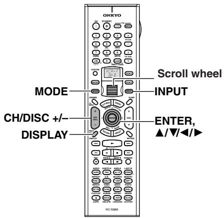
Enjoying Internet Radio
To listen to Internet radio, the connection/configuration requirements listed on pages 72-73 must be satisfied.
| 1 ↑ | While neither the [INPUT] button nor [MODE] button is illuminated, roll the scroll wheel to select IRD (Internet Radio). “NET-T” appears in the bottom line. On the TX-NR1000/TX-NR5000E, press the [NET AUDIO] button. This button switches between two alternative settings: Server and Internet Radio. |
| 2 | Press the [DISPLAY] button on the remote controller. If the main menu has been already displayed, go to the next step. |
| 3 | Use the [▲]/[▼] buttons to select one of the main menus: Genre, Location, or Language. To cancel, press the [←] button. |
| 4 ENTER | Press the [ENTER] button. Wait while your requested data is down-load from the XiVA Internet Radio Service. * What is the XiVA Internet Radio Service? The XiVA Internet Radio Service provides tuning information, allowing you to select from a large number of stations. You can find Internet Radio Stations based on your interests, musical taste, language, and location. When Genre is selected: Allow a few moments until the Genre menu appears. When the main list of genres appears, use the [▲]/[▼] buttons to select the genre desired. Pressing the [ENTER] button brings up the sub-list of the genre you selected, which prompts you to further select one of the items using the [▲]/[▼] buttons. When Location is selected: The list containing names of countries appears. Use the [▲]/[▼] buttons to select the desired item. When Language is selected: The list of languages appears. Use the [▲]/[▼] buttons to select your desired item. If no list is found, “No List” appears. You can return from this screen to the previous selection screen by pressing the [▲] button. |
| 5 ENTER | Press the [ENTER] button. You are presented with a list of radio station names. |
| 6 ENTER | Use the [▲]/[▼] buttons to select one of the radio stations. You can return to the previous step by pressing the [▲] button. |
| 7 ENTER | Press the [ENTER] button. Buffering starts with the following message displayed. Buffering 90K When the buffering is complete, the TX-NR1000/TX-NR5000E starts play-back of the broadcast. Note: If you're using a narrowband Internet connection (e.g., 56K modem, ISDN), depending on the station, Internet radio may not work satisfactorily. For best results use a broadband connection (e.g., cable modem, xDSL modem, etc). You can switch the displayed content using the [▲]/[▼] buttons. After the switch operation, the display mode appears for 3 seconds, and then the appropriate information scrolls. If there is no information on title or artist, “No Info” appears. When using the OSD screen, all the information is displayed on one screen without scrolling. | Choosing a Preset Internet Radio Station | |
| 1 | While neither the [INPUT] button nor [MODE] button is illuminated, roll the scroll wheel to select IRD (Internet Radio). | ||
| 2 | Use the remote controller's [CH DISC +/- ] button to select the preset. When you choose a preset station, the station name is displayed for 5 seconds, and then the progress of buffering is displayed instead. Station ONK CH DISC When the progress of buffering reaches 100%, you will be presented with the playing screen. | ||
| Erasing a preset Internet radio station | |||
| OSD iNet Radio Station ONK 7ch Title: Station ONK Live Program: Station ONK Live Artist: RealOnkyoNet.com Data: WMA 20kbps Tuned | 1 | Select the station to erase, following the instructions described above. | |
| 2 | Press the [▶] button. Station ONK 10°. The TX-NR1000/TX-NR5000E enters | ||
| Display Station ONK | |||
Presetting Internet Radio Stations
| You can preset up to 30 Internet radio stations. | |
| 1 | Receive your desired station. |
| 2 | Press the [▶] button. The TX-NR1000/TX-NR5000E enters into preset mode; the currently selected preset number blinks for 5 seconds. Preset number Station ONK 10° |
| 3 | Press the [ENTER] button. The preset is now complete. |
Choosing a Preset Internet Radio Station
| 1 | While neither the [INPUT] button nor [MODE] button is illuminated, roll the scroll wheel to select IRD (Internet Radio). |
| 2 | Use the remote controller's [CH DISC +/- ] button to select the preset. When you choose a preset station, the station name is displayed for 5 seconds, and then the progress of buffering is displayed instead. Station ONK ↓ Buffering 90K When the progress of buffering reaches 100%, you will be presented with the playing screen. |
| Erasing a preset Internet radio station | |
| 1 | Select the station to erase, following the instructions described above. |
| 2 | Press the [▶] button. Station ONK 10 The TX-NR1000/TX-NR5000E enters into preset erase mode. |
| 3 | Press the [ENTER] button. Your selected station is erased. |
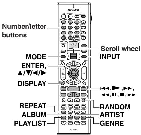
Playing a Music File Saved on the Net-Tune Server
To play music files saved on your PC, the requirements listed on page 72 must be satisfied.
| 1 | Turn on the Net-Tune server. Wait until the Net-Tune server starts up. It may take a few seconds. |
| 2 | Turn on the TX-NR1000/TX-NR5000E. When you connect the TX-NR1000/ TX-NR5000E to the network the first time, it will be connected to the first server found. |
3 While neither the [INPUT] button nor [MODE] button is illuminated, roll the scroll wheel to select MSRV (Music Server).
"NET-T" appears in the bottom line. On the TX-NR1000/TX-NR5000E, press the [NET AUDIO] button. This button switches between two alternative settings: Server and Internet Radio. Until the TX-NR1000/TX-NR5000E connects to the network, finds the server, and completes the connection, "Network Starting..." and "Connecting..." appears. After completing the connection to the Net-Tune server, the display changes to the normal indication. If the following messages appear, check the message meaning and perform the appropriate procedures.
"No Track"
The Net-Tune server could not retrieve any track information. Register tracks with the Net-Tune server. If you have already registered tracks, use the [DISPLAY], [ARTIST], [ALBUM], [GENRE], and [PLAYLIST] buttons to display information.
"Disconnected"
The Net-Tune server may not start or the server connected to previously may not be found. Confirm the connections between router, the Net-Tune server, and the TX-NR1000/TX-NR5000E. Start the Net-Tune server or select another server referring to "Select Server" on "Music Server Sub-menu" (See page 95).
4
Remote controller

Press the [▶] button to play the music file.
The TX-NR1000/TX-NR5000E provides five normal display modes; you can use the [] / [] button to switch among them.
OSD
| Music Server | Play |
| Track: 1/12 | 1m20s> |
| My sweet candy | |
| Album: | |
| My Best 100 | |
| Artist: | |
| Happy PanPot | |
| Data: | |
| MP3 | 160kbps |
Display
1n 1m20s
- To stop playback:
Press the [ ] button on the remote controller. - To pause playback:
Press the [ ] button on the remote controller. - To select a track:
Press the [ ] / [ ] button on the remote controller.
Press the [▶▶] button to move to the next track.
Press the [▶] button to move to the beginning of the current track; hold down the [▶] button to move to the previous track.
You can also use the number/letter buttons to select a track.
Examples:
To select number 3, press 3.
To select number 10, press --/----, 1 and 0.
To select number 37, press --/----, 3 and 7.
To select number 123, press --/--- twice, and then press 1, 2 and 3.
To select number 2568, press --/--- third, and then press 2, 5, 6, and 8.
- To fast forward/reverse the music:
Press and hold the [ ] button on the remote controller to fast forward the music; press and hold the [ ] button to fast reverse the music. When the music track is back at its beginning, normal playing starts.
- To switch to the track list:
While playing the music, you can press the [■] button to display a list of currently open tracks.
Selecting a Track List
You can use the music file data saved on the Net-Tune server to select which tracks to play.
For example, you can:
- Select a track list based on the album name
- Select a track list based on the artist name
- Select a track list based on the genre name
- Select a play list
1 Press either the [ALBUM], [ART-IST], [GENRE], or [PLAYLIST] button on the remote controller.
Search the tracks stored on the Net-Tune server with your selected mode to display it in the display.
In the artist and album modes, the tracks are displayed in alphabetical order.
You can also use the procedure below.
- Press the [DISPLAY] button.
- You can press the [] / [] buttons to cyclically switch among the four modes: Albums Artists Genres Playlists.
- Press the [ENTER] button.
Use the [ ] / [ ] buttons to select one from the menu.
![ONKYO TX-NR1000 - Use the [ ] / [ ] buttons to select one from the menu. - 1](/content/2025/01/151762/images/f800938ae489ea0137267819bf05677af1c047091fca4c3fd3d90927078e1242.jpg)
At this time, pressing [<] button brings you one step back where you can change the selection you made.
Also, pressing [▶] button in the genre or artist selection mode will display a list of albums with the genre or artist you selected.
In the album, artist, or playlist selection mode, using the number/letter buttons will accelerate your selection operation (See below).
3 Press the [ENTER] button.
The title of your selected track appears.
You can choose another track by pressing the [] / [] buttons.
Press the [ ] button to return to the previous step.
You can also select the list number using the number/letter buttons.
4 Press the [ENTER] button.
The playback begins.
Using the number/letter buttons
![ONKYO TX-NR1000 - Press the [ENTER] button. - 1](/content/2025/01/151762/images/37c7d925f564d7021c21f3a984fda178fc3475f56ab3e3add7f7f7e9a07d4f5e.jpg)
The number/letter buttons allow you to input one of the letters or numbers printed on their key tops. Pressing the [CAPS] button cyclically switches the types of input:
Upper case (A) Lower case (a) Numeric value (2) ... When your desired input type is selected, then press the number/letter button.
Let us take the [2ABC] button as an example to see the operation.
When the upper case is selected:
Pressing the button once will perform a search by the letter "A." Pressing twice will do a search by "B," pressing three times by "C."
When the lower case is selected:
Pressing the button once will perform a search by the letter "a." Pressing twice will do a search by "b," pressing three times by "c."
When the numeric value is selected:
Pressing the button once will perform a search by the numeric value "2."
To cancel the operation:
Notes:
- Press the [DELETE] button to delete the entered letter or number.
- Pressing the [DISPLAY] button on the main unit will display the current listening mode.
Playing a Music File At Random

Press the [RANDOM] button on the remote controller when in stop mode.
This button displays the current random settings and switches between two alternative settings: On and Off.
On: Randomly plays the tracks in the currently selected mode.
Off: Random mode is disabled.
After the necessary settings are complete, press the [▶] button.
Playing a Music File Repeatedly

Press the [REPEAT] button on the remote controller.
This button displays the current repeat settings and cyclically switches among three alternative settings: Repeat 1 All Off.
Repeat 1: Repeats the current track only. Repeat All: Repeats the tracks in the currently selected mode.
Repeat Off: Repeat mode is disabled.
You can operate the TX-NR1000/ TX-NR5000E when playing and when stopped.
Configuring the Music Server
The music server settings can be made while you select the music server as an input source.
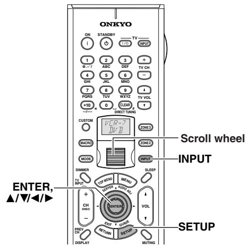
Press the [INPUT] button, and then roll the scroll wheel to select MSRV.
Make sure that the "MSRV" is displayed when you configure the music server.
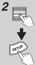
Press the scroll wheel, and then press the [SETUP] button to display the Main Menu.

3
Use the [ ] / [ ] buttons to select "Input Setup," then press the [ENTER] button.

Use the [ ] / [ ] buttons to select the "Music Server" sub-menu, then press the [ENTER] button.
The setup screen for the sub-menu appears.

Use the [▲] and [▼] cursor buttons to select "Select Server" and then use the [▲] and [▶] cursor buttons to select the desired server.
Select a network server that exists on the network.
- mark appears next to the servers detected on the network. If there is a server that does not have a * mark, make sure that the server is running. "Not
Found" message indicates that no server is currently available for selection. If the message appears, make sure that the server is connected and running.

6
Press the [SETUP] button.
This completes the configuration procedure and the menu disappears.
Tips:
When choosing settings on the TX-NR1000/TX-NR5000E, after selecting the input source using the input source buttons, press the [SETUP] button. Next, select the menu you want to configure by turning the [SELECT/PRESET] dial and press the dial to confirm the selection. Then, after selecting the submenu you want to configure by turning the [SELECT/PRESET] dial, select your value by turning the [CONTROL/TUNING] dial, and press the dial to confirm the value. If you want to go back to the previous operation, press the [EXIT] button.
Enjoying Net Audio—Continued
| Music Server Memo | Internet Radio Memo |
Setup Menu
When making the various settings required to configure your TX-NR1000/TX-NR5000E for optimum performance, you can use either the OSD Menu that appears on your television monitor or you can use the display on the front of the TX-NR1000/TX-NR5000E. The OSD Menu is a settings menu that is displayed on your TV monitor.
The TX-NR1000/TX-NR5000E is equipped with an independent Setup Menu not only for Main room A but also for Main room B and Zone 2 room, which allows you to specify settings for each room. The Setup Menu includes various menus. These menus are then divided into various sub-menus, and these contain settings for you to optimize your home theater as you wish.
The display shown below is an example. The actual contents of your display may differ depending on the model for your region and the selected input source.
For more information on operating instructions, see page 86.
OSD Map (MAIN A)
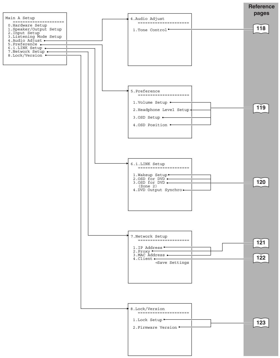
OSD Map (MAIN B)
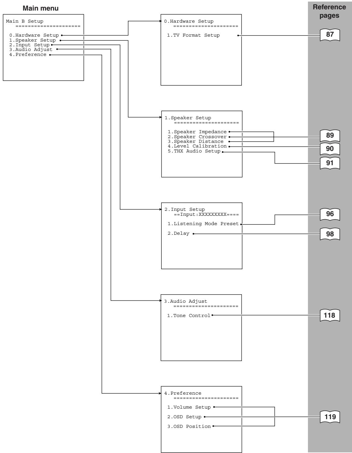
OSD Map (ZONE 2)
The Zone 2 settings shown on this page can be made when you perform either of the following settings in the "MAIN A" setup menu.
- Under the "Speaker/Output Setup Speaker Configuration" menu, when you select the surround back setting to "Powered Zone 2." (The main menu 1 below)
- Under the "Speaker/Output Setup Audio (Video) Output Assign" menu, when you select the output terminal setting to "Zone 2 Out." (The main menu 2 below)
(Main menu 1)
Zone 2 Setup
0.Hardware Setup
1.Speaker Setu
2.1 input setup
3. Listening Mode Setup
4. Audio Adjust 5. D
(Main menu 2)
Zone 2 Setup
0.Hardware Setup
- Input Setup
- Listening Mode Setup
- Audio Adjust
- Preference
0.Hardware Setup
1.TV Format Setup
1.Speaker Setup
1.Speaker Impedance
-
Input Setup = Input:XXXXXXXX = = = =
-
Listening Mode Preset
2DELAY
Reference pages
87
89
96
98
99
100
106
108
109
116
118
-
Listening Mode Setup
1.Mono Setup
2.Multiplex Setup
3.Stereo Setup
4.Dolby Digital Setup
5.DTS Setup
6.AAC Setup
7.Dolby Virtual Speaker Setup -
Audio Adjust
1.Tone Control
- Preference
1.Volume Setup
2.OSD Setup
3.OSD Position
119
Navigating the Setup Menu
You can change Setup Menu settings using the buttons on the front panel and on the remote controller. The illustrations here represent the remote controller.
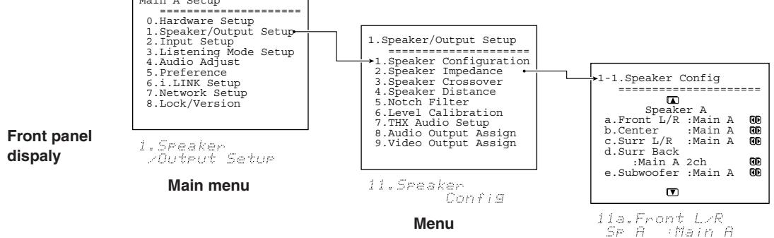
OSD
Sub-menu
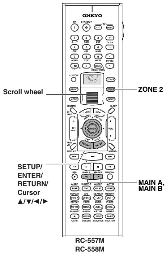
1 Press the scroll wheel when using the remote controller.
2 Press the button of the room where you want to perform operations. Press [MAIN A], [MAIN B], or [ZONE 2].
If the room where you want to perform operations has already been activated, you do not have to press the button here. Pressing the button while the corresponding room is activated deactivates the room for setup.
3 Press the [SETUP] button.
The main menu appears on your television monitor.
4 Using the [▲] and [▼] cursor buttons, select the menu that you want to enter.
5 Press the [ENTER] button to enter the selected menu.
The screen for that menu appears.
6 Use the [▲] and [▼] cursor buttons to select the sub-menu that you want to enter and press the [ENTER] button.
Each sub-menu has different settings that can be changed as desired, and they are all explained in the pages that follow. To change a setting, first select it using the [▲] and [▼] cursor buttons, and then change the setting using the [▲] and [▼] cursor buttons.
7 Press the [SETUP] button to exit the Setup Menu.
Press the [RETURN] button to set the new settings and return to the previous menu.
When you perform settings using the buttons on the front panel, press the [SETUP] button first. Use the [SELECT/PRESET] dial instead of the [ ] / [ ] buttons to select menus or parameters and press the dial to confirm your selection. Then use the [CONTROL/TUNING] dial instead of the [ ] / [ ] buttons to select your setting or parameter values and press the dial to confirm your selection. In addition, the [EXIT] button is used instead of the [RETURN] button.
Hardware Setup
In this section, you will perform the initial settings for the following scenarios.
- When you want to change the TX-NR1000/TX-NR5000E's remote control ID.
- When you want to fix the TV Format setting to PAL or NTSC.
- When you want to fix the AM Frequency Step setting to 9kHz or 10kHz .
Remote Control Setup Sub-menu
Remote ID
This section explains how to change the TX-NR1000/ TX-NR5000E's remote control ID. You may need to change this if the TX-NR1000/TX-NR5000E's remote controller interferes with other Onkyo components located in the same room. You can select 1, 2, or 3 for remote control ID.
If you change the TX-NR1000/TX-NR5000E's remote control ID, be sure to select the same ID on the remote controller (See page 142). The default ID for both the TX-NR1000/TX-NR5000E and remote controller is 1.
Note:
It is recommended that you perform setup using the [SETUP]/[SELECT/PRESET]/[CONTROL/TUNING]/[EXIT] buttons of the TX-NR1000/TX-NR5000E's front panel.
If the remote controller is used for setup, signals from the remote controller will not be received just after the remote control ID settings have been changed (See "Changing the Remote Controller's Control ID" on page 142 to change the remote control ID on the remote controller).
TV Format Sub-menu
TV Format (for all models other than USA and Canadian models)
The settings in the TV Format sub-menu can be configured for Main B and Zone 2 as well as for Main A. When you want to reconfigure the settings to conform to the television format used in the area where you use the TX-NR1000/TX-NR5000E, use this sub-menu so that no time is wasted on detection.
Auto: This is the default setting. When you leave this setting unchanged, the television format is detected and automatically set by the TX-NR1000/TX-NR5000E.
PAL: Use this setting when you know the television format is PAL.
NTSC: Use this setting when you know the television format is NTSC.
AM Frequency Setup Sub-menu (Asian and Australian Models Only)
Frequency Step
The setting in this sub-menu determines the incremental or decremental amount when adjusting the AM tuner frequency. The initial setting is 9kHz and this only needs to be changed if you are using the TX-NR1000/ TX-NR5000E in a 10kHz region.
9 kHz: Select if 9 kHz increments are used in your area.
10 kHz: Select if 10 kHz increments are used in your area.
Speaker/Output Setup
The TX-NR1000/TX-NR5000E provides a wide range of variations in speaker connections and speaker settings, so you have to specify speaker settings according to conditions of each variation. For proper selection of an AV device connected at switching of the input type, you also need to allocate "audio output" and "video output" to each input type. If this allocation is incorrect, the desired component will not play a selected input source.
Please setup correctly by referring to the information you wrote down in the Your System Setting booklet.
Speaker Configuration Sub-menu
Specify the rooms where you want to use speakers connected to the SPEAKERS A terminal and the SPEAKERS B terminal. Specify according to settings for main room A.
Note:
Basically, a speaker set with the maximum number of speakers should be connected to the SPEAKERS A terminals and configured for main room A (Main A). When either the center, surround, or surround back speakers are not connected to the SPEAKERS A terminals, or any of these speakers is set to "Not Used" in the Speaker A settings, you cannot perform the settings for the corresponding speakers connected to the SPEAKERS B terminals and those speakers connected to the SPEAKERS B terminals cannot be used.
(Speaker A) Front L/R
The setting of the front speakers is initially fixed to Main A.
Always install speakers connected to FRONT L/R of SPEAKERS A in main room A.
(Speaker A) Center, Surr L/R
Main A (default): Select this when using the center speaker and/or surround speakers in main room A.
Not Used: Select this when not using a center speaker or surround speakers.
(Speaker A) Surr Back
Main A 2ch (default): If Surr L/R is set to "Main A," you can select this item. Select this when connecting and using two surround back speakers in main room A.
Main A 1ch (SBL): If Surr L/R is set to "Main A," you can select this item. Select this when connecting and using a surround back speaker in main room A.
BTL for Front: Select this when using the front speaker in main room A by connecting the surround back channel to the speaker via BTL (See page 27).
Bi-Amp for Front: Select this when using the front speaker in main room A by connecting the front channel and the surround back channel to the speaker via Bi-Amp (See page 27).
Not Used: Select this when not using surround back speakers.
Note:
If "Not Used" is selected for Surr L/R, this item defaults to "Not Used."
(Speaker A) Subwoofer
Main A (default): Select this when using a subwoofer in the main room A.
Not Used: Select this when not using a subwoofer in the main room A.
(Speaker B) Front L/R
Main A: Select this when using in main room A.
Main B: Select this when using in main room B.
Not Used (default): Select this when not using.
(Speaker B) Center
Main A: Select this when using in main room A.
Main B: Select this when using in main room B. This setting can only be made when you set the "(Speaker B) Front L/R" setting to "Main B."
Not Used (default): Select this when not using.
(Speaker B) Surr L/R
Main A: Select this when using in main room A.
Main B: Select this when using in main room B. This setting can only be made when you set the " (Speaker B) Front L/R" setting to "Main B."
Not Used (default): Select this when not using.
(Speaker B) Surr Back
Main A 2ch: Select this when connecting and using two surround back speakers in main room A.
Main A 1ch (SBL): Select this when connecting and using a surround back speaker in main room A.
Main B 2ch: If (Speaker B) Front L/R and Surr L/R are both set to "Main B," you can select this item. Select this when connecting and using two surround back speakers in main room B.
Main B 1ch (SBL): If (Speaker B) Front L/R and Surr L/R are both set to "Main B," you can select this item. Select this when connecting and using a surround back speaker in main room B.
Powered Zone 2: Select this when using in Zone 2.
- If (Speaker A) Surr Back is set to "BTL for Front" or "Bi-Amp for Front," this item is not displayed (Because, if "Powered Zone 2" is set, BTL connection and/or Bi-Amp connection are disabled).
BTL for Front: This setting can be made only when you set the " (Speaker B) Front L/R" setting to "Main A" or "Main B." Select this when using the front speaker in main room B by connecting the surround back channel to the speaker via BTL (See page 27).
Bi-Amp for Front: This setting can be made only when you set the " (Speaker B) Front L/R" setting to "Main A" or "Main B." Select this when using the front speaker in main room B by connecting the front channel and the surround back channel to the speaker via Bi-Amp (See page 28).
Not Used (default): Select this when not using surround back speakers.
Note:
If (Speaker A) Surr Back is set to "Main A 1ch," you cannot select "Main A 2ch" and "Main B 2ch" here.
(Speaker B) Subwoofer
This setting can be made only when you set the "(Speaker B) Front L/R" setting to "Main A" or "Main B."
Main A: Select this when using a subwoofer in main room B.
Main B: Select this when using a subwoofer in main room B. This setting can only be made when you set the " (Speaker B) Front L/R" setting to "Main B."
Not Used (default): Select this when not using a subwoofer.
When the settings for Speaker Configuration are completed, the subsequent settings should be specified separately in main room A, main room B, and Zone 2.
Speaker Impedance Sub-menu
Use this sub-menu to set the impedance level of the TX-NR1000/TX-NR5000E to match the specifications of the speakers you are using. The settings in the Speaker Impedance sub-menu can be configured for Main B and Zone 2 as well as for Main A.
The selectable parameters are common to all items.
Note:
Before you change this setting, be sure to first lower the volume at the TX-NR1000/TX-NR5000E to the minimum level.
8 ohms (default): Select this when the impedance of the connected speaker is 8 ohms or more.
6 ohms: Select this when the impedance of the connected speaker is no lower than 6 ohms and no higher than 8 ohms.
4 ohms: Select this when the impedance of the connected speaker is no lower than 4 ohms and no higher than 6 ohms.
- When "BTL for Front" is selected for "Surr Back" from the Speaker Configuration sub-menu, the corresponding "Front L/R" is automatically fixed to "8 ohms," and the impedance settings for the surround back speakers are also removed. Please verify that the impedance of a connected speaker is 8 ohms or more.
- For any speaker that is not available or set to "Not Used" in the Speaker Configuration sub-menu, no associated setting item is displayed.
Speaker Crossover Sub-menu
The settings in the Speaker Crossover sub-menu can be configured for both "Main A" and "Main B."
Front L/R, Center, Surr L/R, Surr Back
Specify a threshold frequency in Hz for bass sounds from each speaker to be output from the subwoofer. When no subwoofer is used, (Speaker A) Front L/R is automatically set to "Full Band," and bass sounds from each speaker are output from the front speakers. You can also set other speakers to "Full Band."
You can specify the frequency at 10Hz increments between 40-150 Hz. When using a THX-Select-certified speaker system, specify the setting of 80 Hz (THX) (default).
- If you specify the frequency of the front speakers between 40 - 150Hz , you cannot select "Full Band" for the other speakers.
- For any speaker that is not available or set to "Not Used" in the Speaker Configuration sub-menu, no associated setting item is displayed.
- If "Surr Back" is set to "BTL for Front" or "Bi-Amp for Front" on the Speaker Configuration sub-menu, no item for surround back speakers is displayed.
LPF of LFE (setting of the low-pass filter for LFE)
Specify the low-pass filter for LFE (Low Frequency Effect).
The low-pass filter passes through only the signal components below the specified frequency, eliminating the unwanted noise.
You can specify the frequency at 10Hz increments between 40 - 150Hz .
SW Mode (Subwoofer Mode)
This item is displayed when a subwoofer is used (any item other than "Not Used" is selected for Subwoofer on the Speaker Configuration sub-menu), and Front L/R is set to "Full Band" on the Speaker Crossover sub-menu. Set the sound from the subwoofer to any of the following:
LFE only: The subwoofer outputs only LFE (Low Frequency Effect) information.
D. Bass: The subwoofer outputs not only LFE (Low Frequency Effect) factors but also bass sounds from the front speakers.
Speaker Distance Sub-menu
Measure the distance between the listening position and each speaker. Specifying the distance will synchronize the speakers in terms of the time that sounds from each speaker reach the listening position. This is an important specification for you to enjoy realistic home theater. The settings in the Speaker Distance sub-menu can be configured for both "Main A" and "Main B."
Perform the setup procedure below following the operating instructions described on page 86.
- Select the unit of distance from "Unit."
You can select either "feet" or "meters." The default varies depending on the region.
-
Set the distance you measured. Enter all the values for every speaker you connected.
-
For any speaker that is not available or set to "Not Used" in the Speaker Configuration sub-menu, no associated setting item is displayed.
- If "Surr Back" is set to "BTL for Front" or "Bi-Amp for Front" on the Speaker Configuration sub-menu, no item for surround back speakers is displayed.
When "feet" is selected:
Front L, Center, Front R, and Subwoofer can be set at 0.1 foot intervals in a range from 1.0 foot to 30.0 feet. The default is 12.0 feet.
Surr R, Surr Back (or Surr Bk R and Surr Bk L), and Surr L can be set at 0.1 foot intervals in a range from 1.0 foot to 30.0 feet. The default is 7.0 feet.
When "meters" is selected:
Front L, Center, Front R, and Subwoofer can be set at 0.03 meter intervals in a range from 0.30 meters to 9.00 meters. The default is 3.60 meters.
Surr R, Surr Back (or Surr Bk R and Surr Bk L), and Surr L can be set at 0.03 meter intervals in a range from 0.30 meters to 9.00 meters. The default is 2.10 meters.
Notch Filter Sub-menu
To configure the settings under the Notch Filter submenu, a special measuring device is required. Usually, leave these settings to their defaults, "Off."
A notch filter cuts the signal of certain frequency ranges and passes the rest of the signal through. Some characteristics due to a room's environmental elements, including walls and smallness of the room, cause a signal peak in certain low frequencies to occur at the resonance frequency, resulting in a boomy sound. The filter reduces the signal at these frequencies causing the boomy sound.
To know which frequency the peak occurs at, use a low frequency sine wave generator and SPL (Sound Pressure Level) meter to check the frequency and the notch value.
Notch Filter
Off(Default): Select this setting when not applying the notch filter.
On: Select this setting when applying the notch filter.
Frequency
When setting "Notch Filter" above to "On," the notch filer becomes effective at the frequency you specify here. With your measuring device, the frequency value can be set at 1Hz intervals in a range from 20Hz to 300Hz . The default is 100Hz .
Depth
When setting "Notch Filter" above to "On," the notch filter becomes effective at the value you specify. You can specify intervals of 0.5 dB in a range from -15 dB to 0dB . The default is -10dB .
Width
The available setting values are calculated based on the values specified in the "Frequency" and "Depth" settings above. You can choose any values according to your favorite sound.
Level Calibration Sub-menu
Use this sub-menu to set the volume for each speaker so that each volume is heard by the listener at the same level. This is especially important for speaker layouts where the left and right speakers are at different distances or in asymmetrical positions due to room designs and configurations. These settings and the distance settings performed in the Speaker Distance sub-menu are vital for creating proper sound space and dynamics. The settings in the Level Calibration sub-menu can be configured for both "Main A" and "Main B."
- These settings cannot be made when the sound is muted, when you connect the headphones, and when you use multichannel playback.
- You cannot use the [MASTER VOLUME] dial while you perform the Level Calibration settings. These settings are intended to bring sound levels between speakers into balance so as to obtain the proper sound space.
- This unit supports the THX format and the test tone is output at a standard 0 dB (the Absolute Volume value is 82). If you usually enjoy listening at a lower level than the test tone, be careful of the test tone's sudden loud sound. Note that the test tone will be output immediately after pressing the [ENTER] button in step 1 below.
- When you display this setting screen, select "Level Calibration," and press the [ENTER] button, the display changes to the Level Calibration screen, and at the same time, a sound is emitted from the front left speaker.
- Starting with the front speaker, press the [] / [] buttons to select a speaker, and press the [] / [] buttons to set the volume level. When you have set all connected speakers, the setup is complete.
You can adjust in the range from -12dB to +12dB in 0.5 dB step. The subwoofer can be adjusted in the range from -15dB to +12dB in 0.5 dB step.
- For any speaker that is not available or set to "Not Used" in the Speaker Configuration sub-menu, no associated setting item is displayed.
- If "Surr Back is set to "BTL for Front" or "Bi-Amp for Front" on the Speaker Configuration sub-menu, no item for surround back speakers is displayed.
THX Audio Setup Sub-menu
This is for setting up a home theater with a THX-Ultra2 compliant speaker system. These settings will be effective in the listening mode for the THX Ultra2 Cinema and THX Music Mode. The settings in the THX Audio Setup sub-menu can be configured for both "Main A" and "Main B."
THX Ultra2 Subwoofer A/THX Ultra2 Subwoofer B
This is for setting the connected subwoofer. Select "Yes" or "No" according to your subwoofer's specification.
Yes: Set "Yes" if your subwoofer conforms to the THX Ultra2 standard or if the playback capability of its bass range extends down to 20Hz . Otherwise, set "No."
No(Default):Set"No"if you use any subwoofer that does not fit the conditions above.
- For any speaker that is not available or set to "Not Used" in the Speaker Configuration sub-menu, no associated setting item is displayed.
Boundary Gain Compensation A/ Boundary Gain Compensation B
This is for setting the correction of boundary gains. This item can be set when "THX Ultra2 Subwoofer" is set to "Yes."
Room boundaries (walls) or other characteristics (such as construction materials) may increase the perceived acoustics levels at low frequencies. Depending on the listener's and the subwoofer's position, the listener may experience an excessive bass effect.
The purpose of this feature is to compensate for excessive bass resulting from a boundary gain effect.
On: Boundary Gain Compensation is applied.
Off (Default): Boundary Gain Compensation is not applied.
Distance Between Surr Back A SP/ Distance Between Surr Back B SP
This setting is allowed only when "Main 2ch" is selected from the Speaker Configuration sub-menu. Place two surround back speakers as close together as possible, measure the distance, and set the value (See the figure). The maximum effects will be realized by THX's ASA* technology.
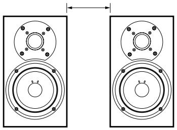
0-1 ft (0-0.3 m)(Default): This is the setting when the distance between the speakers is 0-1 foot (0 - 30cm)
1-4 ft (0.3-1.2 m): This is the setting when the distance between speakers is 1-4 feet (30 cm-1.2 m).
>4 ft (1.2m) : This is the setting when the distance between speakers is 4 feet (1.2m) or more.
*ASA: Advanced Speaker Array
Audio Output Assign Sub-menu
This setting allocates audio output jacks on the TX-NR1000/TX-NR5000E to input (play) sources. The setting varies depending on the connection conditions. The TX-NR1000/TX-NR5000E is equipped with analog output jacks for five lines, and digital output jacks: optical jacks (OPT) for two lines, and coaxial jacks (COAX) for two lines. If setting the analog jacks to "Zone 2 Out" or "Zone 3 Out," you can also specify whether output should be variable or fixed.
The default settings are as follows:
| Terminals | Default input settings |
| Analog 1 (AUDIO OUT 1) | Video 1 Rec Out |
| Analog 2 (AUDIO OUT 2) | Video 2 Rec Out |
| Analog 3 (AUDIO OUT 3) | Video 3 Rec Out |
| Analog 4 (AUDIO OUT 4) | Zone 2 Out |
| Analog 5 (AUDIO OUT 5) | Zone 3 Out |
| Opt 1 Out (DIGITAL OUT OPTICAL 1) | Tape 1 Rec Out |
| Opt 2 Out (DIGITAL OUT OPTICAL 2) | Tape 2 Rec Out |
| Coax 1 Out (DIGITAL OUT COAXIAL 1) | Video 1 Rec Out |
| Coax 2 Out (DIGITAL OUT COAXIAL 2) | Zone 2 Out |
Analog 1-5
Set the analog audio output jacks of "AUDIO OUT 1-5." You can select from Tape 1 Rec Out, Tape 2 Rec Out, Video 1 Rec Out, Video 2 Rec Out, Video 3 Rec Out, Zone 2 Out, Zone 3 Out, and Not Used.
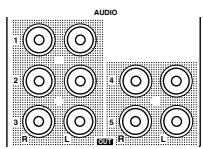
Example 1:
When input (REC) of a sound recording device (e.g., a cassette deck) with TAPE 1 as an input source is connected to AUDIO OUT 1, set "Analog 1" to "Tape 1" Rec Out.
Example 2:
When sound input of a picture recording device (e.g., a VCR) with VIDEO 1 as an input source is connected to AUDIO OUT 2, set "Analog 2" to "Video 1 Rec Out."
Example 3:
When the amplifier for Zone 2 is connected to AUDIO OUT 5, set "Analog 5" to "Zone 2 Out."
When nothing is connected: Select "Not Used."
Zone 2 Out, Zone 3 Out
This item is displayed when "Zone 2 Out" or "Zone 3 Out" is specified for Analog 1-5 above. The default setting for "Zone 2 Out" is "Pre Out (variable)" and for "Zone 3 Out" is "Line Out (fixed)."
Pre Out (variable): Select this when you want to set "variable" for output to a device connected to Zone 2 or Zone 3. You should operate the TX-NR1000/ TX-NR5000E to adjust the sound volume from the device in Zone 2 or Zone 3.
Line Out (fixed): Select this when you want to set "fixed" for output to a device connected to Zone 2 or Zone 3. You should operate the amplifier connected to the terminal to adjust the sound volume from the device in Zone 2 or Zone 3.
Opt 1 Out, Opt 2 Out, Coax 1 Out, Coax 2 Out
Specify a setting for "DIGITAL OUT OPTICAL 1-2" and "DIGITAL OUT COAXIAL 1-2."
You can select from Tape 1 Rec Out, Tape 2 Rec Out, Video 1 Rec Out, Video 2 Rec Out, Video 3 Rec Out, Zone 2 Out, Zone 3 Out, and Not Used.
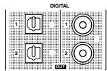
Example 1:
When input (REC) of an audio recording device (e.g., an MD recorder) with TAPE 2 as an input source is connected to DIGITAL OUT OPTICAL 1, set "Opt 1 Out" to "Tape 2 Rec Out."
Example 2:
When input (IN) of a picture recording device (e.g., a DVD recorder) with VIDEO 2 as an input source is connected to DIGITAL OUT OPTICAL 2, set "Opt 2 Out" to "Video 2 Rec Out."
When nothing is connected: Select "Not Used."
HDMI Out
This setting allows you to enable/disable audio output from the HDMI terminal. Use this setting when the HDMI terminal of a TV is connected to the HDMI terminal of the TX-NR1000/TX-NR5000E and you want to enable HDMI audio output of the TX-NR1000/ TX-NR5000E from the TV speakers. Usually leave this setting to its default, "Disable."
Disable(Default):DisablesHDMI audio output.
Enable: Enables HDMI audio output.
Video Output Assign Sub-menu
This setting allocates video output jacks on the TX-NR1000/TX-NR5000E to input (play) sources. The setting varies depending on the connection conditions.
The TX-NR1000/TX-NR5000E is equipped with composite video output jacks for four lines, and S video output jacks for four lines.
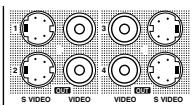
The default settings are as follows:
| Terminals | Default input settings |
| Composite Video 1 (VIDEO OUT 1) | Monitor Out B |
| Composite Video 2 (VIDEO OUT 2) | Zone 2 Out |
| Composite Video 3 (VIDEO OUT 3) | Zone 3 Out |
| Composite Video 4 (VIDEO OUT 4) | Monitor Out A (fixed) |
| S-Video 1 (SVIDEO OUT 1) | Video 1 Rec Out |
| S-Video 2 (SVIDEO OUT 2) | Video 2 Rec Out |
| S-Video 3 (SVIDEO OUT 3) | Video 3 Rec Out |
| S-Video 4 (SVIDEO OUT 4) | Monitor Out A (fixed) |
Composite Video 1-3, S-Video 1-3
This is a setting for the composite video output jacks (VIDEO OUT 1-3) and S video output jacks (SVIDEO OUT 1-3).
For Composite Video 1-3, you can select from Monitor Out A, Monitor Out B, Video 1 Rec Out, Video 2 Rec Out, Video 3 Rec Out, Zone 2 Out, Zone 3 Out, and Not Used.
- You can set "Zone 2 Out" or "Zone 3 Out" only when "Zone 2 Out" or "Zone 3 Out" is selected from the Audio Output Assign sub-menu.
For S Video 1-3, you can select from Monitor Out A, Monitor Out B, Video 1 Rec Out, Video 2 Rec Out, Video 3 Rec Out, and Not Used.
Example 1:
When the video port of a picture recording device (e.g., a VCR) with VIDEO 1 as an input source is connected to VIDEO OUT 2, you should set "Composite Video 2" to "Video 1 Rec Out."
Example 2:
When you want to connect a TV set to VIDEO OUT 3 to watch it in main room A, set "Composite Video 3" to "Monitor Out A."
When nothing is connected: Select "Not Used."
Composite Video 4, S-Video 4
The composite video output jacks (VIDEO OUT 4), and S video output jacks (SVIDEO OUT 4) are fixed to Monitor Out A, you cannot change this setting. You should connect a TV set and a projector used in main room A toVIDEO OUT 4 or SVIDEO OUT 4.
Input Setup
Items described here are set when you press the input source buttons.
The TX-NR1000/TX-NR5000E is equipped with several types of jacks in addition to the standard audio and video jacks, and multiple jacks are provided for each type. You may freely assign input sources such as CD, PHONO, TUNER, TAPE 1, TAPE 2, and VIDEO 1-7 to these jacks.
Moreover, you can preset a listening mode, specify names for display, adjust audio delays, correct the difference in the volume level from other input sources, and set the 12V trigger.
In particular, please be careful when setting the input jacks. Please properly specify settings for correct selection of pictures and audio to be played by referring to the information you wrote down in the Your System Setting booklet. In the case of NET AUDIO, you can specify settings for the server (See page 95).
Settings defaults are as follows:
| OSD Indication | Audio Assign | Video Assign | |||||||
| Analog Audio | Multichannel | Digital Audio | i.LINK | Composite Video | S-Video | Component Video | HDMI | ||
| Name of Terminal to be Set | AUDIO IN | MULTI-CH IN | DIGITAL IN | iLINK | VIDEO IN | SVIDEO IN | COMPONENTVIDEO IN | HDMI IN | |
| Input Selector | NET AUDIO | No | No | No | No | Last | Last | Last | Last |
| CD | 1 | 2 | Opt 2 | No | Last | Last | Last | Last | |
| PHONO | Phono | No | No | No | Last | Last | Last | Last | |
| TUNER | No | No | No | No | Last | Last | Last | Last | |
| TAPE 1 | 2 | No | Opt 3 | No | Last | Last | Last | Last | |
| TAPE 2 | 3 | No | Coax 1 | No | Last | Last | Last | Last | |
| DVD | 4 | 1 | Opt 1 | No | 1 | 1 | RCA 1 | HDMI 1 | |
| VIDEO 1 | 5 | No | Coax 2 | No | 2 | 2 | RCA 2 | HDMI 2 | |
| VIDEO 2 | 6 | No | Coax 3 | No | 3 | 3 | RCA 3 | Video | |
| VIDEO 3 | 7 | No | Opt 4 | No | 4 | 4 | RCA 4/BNC | Video | |
| VIDEO 4 | 8 | No | Opt 5 | No | 5 | No | No | Video | |
| VIDEO 5 | 9 | No | Coax 4 | No | 6 | No | No | Video | |
| VIDEO 6 | No | No | Coax 5 | No | No | 5 | No | Video | |
| VIDEO 7 | Front (fixed) | No | Front Opt (fixed) | No | Front (fixed) | Front (fixed) | No | Video | |
Note: Defaults may differ depending on your region.
Follow procedures below to change any setting:
1 Press the [INPUT] button, and then roll the scroll wheel to select the input source that you want to set.
2 Press the scroll wheel, and then press the [SETUP] button.
The Main Menu appears onscreen.
3 Use the [] / [] buttons to select "Input Setup," and then press the [ENTER] button.
The sub-menu is displayed.
2.Input Setup = = Input:XXXXXX = = = = = = =
- Audio Assign
- Video Assign
- Listening Mode Preset
- Character Edit
5.IntelliVolume
6DELAY
7.Picture Setting
8.12V Trigger Assign
4 Use the [] / [] buttons to select an item you want to set, and then use the [] / [] buttons to set the desired value.
Other items should be selected in the same way.
Press the [RETURN] button.
The display returns to the sub-menu.
6 Repeat procedures 4-5 to set desired items sequentially.
When all of the items are set, go to procedure 7.
7 Press the [SETUP] button.
Settings are completed and the menu screen disappears.
Hint:
When you perform the procedures on the TX-NR1000/ TX-NR5000E, after selecting the input source using the input source buttons, press the [SETUP] button. Next, select the menu you want to configure by turning the [SELECT/PRESET] dial and press the dial to confirm the selection. Then, after selecting the sub-menu you want to configure by turning the [SELECT/PRESET] dial, select your value by turning the [CONTROL/TUNING] dial, and press the dial to confirm the value. If you want to go back to the previous operation, press the [EXIT] button.
Example 1
In assignment of a DVD recorder to input of VIDEO 1, when the analog audio input is connected to "VIDEO 1," the digital audio to "COAXIAL 2," and the video to "SVIDEO 2" and "COMPONENT 2."
- Press the [INPUT] button, and then roll the scroll wheel to select "VIDEO 1."
- Press the scroll wheel, and then press the [SETUP] button to display the Main Menu.
-
Use the [] / [] buttons to select "Input Setup," and then press the [ENTER] button.
-
Use the [] / [] buttons to select "Audio Assign" from the sub-menu, and then press the [ENTER] button.
- Use the [] / [] buttons to select "Analog Audio," and then use the [] / [] buttons to select "1."
- Use the [] / [] buttons to select "Digital Audio," and then use the [] / [] buttons to select "Coax 2."
- Press the [RETURN] button to return to the sub-menu.
- Use the [] / [] buttons to select "Video Assign," and then press the [ENTER] button.
- Use the [] / [] buttons to select "S-Video," and then use the [] / [] buttons to select "2."
- Use the [] / [] buttons to select "Component Video," and then use the [] / [] buttons to select "RCA 2."
- Press the [SETUP] button. Setting is completed and the menu screen disappears.
Audio Assign Sub-menu (when input is other than NET AUDIO)
The following are settings for audio. When input is "NET AUDIO," see the following page.
Analog Audio
The following are settings for analog audio output: Phono: Select the device connected to "AUDIO IN PH."
1-9: Select the device connected to the jack of "AUDIO IN 1-9."
No: Select this when no device is connected.
Multichannel
1: Select the device connected to the jack of "MULTICH IN 1."
2: Select the device connected to the jack of "MULTI-CH IN 2."
No(Default):Select this when no device is connected.
Surr Back Channel
The following are settings for "Multichannel 1" or "Multichannel 2" described above, and cannot be specified separately for each input source. For example, when the input source is CD and "Surround Back Channel" is set to "Not Used (5.1 ch)" for "Multichannel 1," switching the input source to DVD and "Surround Back Channel" to "SBL/SBR (7.1ch)" will also change "Surround Back Channel" associated with CD to "SBL/SBR (7.1ch)."
Not Used (5.1 ch): Select this when not using the surround back channel.
SBL/SBR (7.1 ch) (Default): Select this when using the surround back channel.
Subwoofer Sensitivity
The following are also settings for "Multichannel 1" or "Multichannel 2" (cannot be specified separately for each input source).
Some DVD decks output the LFE channel at -15dB lower than the other channels in the multichannel output.
The level setting under the Level Calibration sub-menu is applied to the analog and digital inputs as well as the multichannel input. Therefore, in this setting, you can set the optimum LFE channel level applied only to the multichannel input.
You can select from 0 (Default), +5, +10 and +15 dB.
Digital Audio
The following are settings for digital audio output.
Opt 1-Opt 6: Select the device connected to "DIGITAL IN OPTICAL 1-6."
Coax 1-Coax 6: Select the device connected to "DIGITAL IN COAXIAL 1-6."
No: Select this when no device is connected.
Digital Format
For digital connections, you can set the digital signals to be detected preferentially. When "Digital Audio" is set to "No" on the Audio Assign Sub-menu above, this item is not displayed.
Auto: Automatically detects the format of input signals. The signal format (Dolby Digital, DTS, PCM, AAC, etc.) used for the selected source is automatically detected, and necessary decoding is performed.
DTS: Select for DTS decoding. You should select this if you feel it takes too long to detect the signals when you have selected "Auto," or if you dislike noises caused by CDs fast forwarding or rewinding.
If any sound other than DTS is input, there is no sound.
PCM: Select for PCM decoding. You should select this if you dislike omission of the top of a subsequent tune when you have selected "Auto."
If any sound other than PCM is input, there is no sound.
Note:
When playing any DTS-type CD or LD, always select "Auto" and "DTS." Selecting "PCM" will cause noises.
i.LINK
When you connect multiple devices using the i.LINK (AUDIO) interface, the device names in the i.LINK connection appear and you can choose the input device from them using the cursor ([] / []) buttons. The device selected here will be the preferred device among the connected i.LINK (AUDIO) devices.
No: Select this when connected i.LINK (AUDIO) devices are not selected as input devices.
Music Server Sub-menu (When input is NET AUDIO)
Select Server
When input Music Server is selected from NET AUDIO, you can specify a server to be connected (See page 78).
Video Assign Sub-menu
The following are settings for video.
Composite Video
1-6: Select the device connected to the "VIDEO IN 1-6" jack.
Last: Select this when you want video signal from the device you last selected to be output.
No: Select this when no device is connected.
S-Video
1-6: Select the device connected to the "SVIDEO IN 1-6" jack.
Last: Select this when you want video signal from the device you last selected to be output.
No: Select this when no device is connected.
Component Video
RCA 1-4: Select the device connected to the "COMPONENTVIDEO IN 1-4" jack.
BNC (European and Asian models only): Select the device connected to the "COMPONENT VIDEO IN" BNC type jack.
Last: Select this when you want video signal from the device you last selected to be output.
No: Select this when no device is connected.
HDMI
1: Select the device connected to the "HDMI IN 1" jack. When selecting this, the video signal from the HDMI IN 1 terminal will also be output to the HDMI OUT terminal.
2: Select the device connected to the "HDMI IN 2" jack. When selecting this, the video signal from the HDMI IN 2 terminal will also be output to the HDMI OUT terminal.
VIDEO: Select this when you want the video signal such as Composite Video, S Video, and Component Video to be output from the HDMI OUT terminal.
Last: Select this when you want video signal from the device you last selected to be output.
No: Select this when no device is connected.
Listening Mode Preset Sub-menu
You can specify a listening mode you frequently use for each input source.
When a picture you like and frequently watch is a Dolby Digital source, for example, you may specify "Dolby Digital," and if a CD of classical music you are fond of is a PCM source, you can specify "Pure Audio." Selecting "Last" will set the same listening mode as the one you last specified for that source.
- If "Surr Back" is set to "BTL for Front," "Bi-Amp for Front," or "Not Used" on the Speaker Configuration sub-menu, the option "PL IIx" is set to "PL II."
- If "Surr L/R" is set to "Not Used" on the Speaker Configuration sub-menu, you cannot select THX, Mono Movie, Enhance, Orchestra, Unplugged, Studio-Mix, or TV Logic.
- If both of "Center" and "Surr L/R" are set to "Not Used" on the Speaker Configuration sub-menu, you cannot select THX, Mono Movie, Enhance, Orchestra, Unplugged, Studio-Mix, TV Logic, All Ch Stereo, or Full Mono.
Analog/PCM
Here, you can specify the listening mode for playing PCM signals from CDs and analog signals from records and cassette tapes. This option can be set for Main B and Zone 2 as well as for Main A.
You can select from the listening modes listed below: (Main A/B)
Pure Audio, Direct, Stereo (Default), Mono, PL IIx/ NEO:6, THX, Mono Movie, Enhance, Orchestra, Unplugged, Studio-Mix, TV Logic, All Ch Stereo, Full Mono, Dolby VS, and Last.
(Zone 2)
Direct, Stereo, Mono, Dolby VS, and Last.
Dolby Digital
Here, you can specify the listening mode for playing Dolby Digital signals. This option can be set for Main B and Zone 2 as well as for Main A.
You can select from the listening modes listed below: (Main A/B)
Pure Audio, Direct, Stereo, Mono, Dolby Digital (Default), THX, Mono Movie, Enhance, Orchestra, Unplugged, Studio-Mix, TV Logic, All Ch Stereo, Full Mono, Dolby VS, and Last.
(Zone 2)
Direct, Stereo, Mono, Dolby VS, and Last.
DTS
Here, you can specify the listening mode for playing DTS signals. This option can be set for Main B and Zone 2 as well as for Main A.
You can select from the listening modes listed below: (Main A/B)
Pure Audio, Direct, Stereo, Mono, DTS (Default), THX, Mono Movie, Enhance, Orchestra, Unplugged, Studio-Mix, TV Logic, All Ch Stereo, Full Mono, Dolby VS, and Last.
(Zone 2)
Direct, Stereo, Mono, Dolby VS, and Last.
AAC
Here, you can specify the listening mode for playing AAC signals. This option can be set for Main B and Zone 2 as well as for Main A.
You can select from the listening modes listed below: (Main A/B)
Pure Audio, Direct, Stereo, Mono, AAC (Default), THX, Mono Movie, Enhance, Orchestra, Unplugged, Studio-Mix, TV Logic, All Ch Stereo, Full Mono, Dolby VS, and Last.
(Zone 2)
Direct, Stereo, Mono, Dolby VS, and Last.
i.LINK (IEEE1394):DVD-Audio
Here, you can specify the listening mode for playing DVD-Audio on a device connected to the i.LINK (AUDIO) terminal.
You can select from the listening modes listed below: (Main A/B)
Pure Audio, Direct, Stereo, Mono, DVD-Audio (Default), THX, Mono Movie, Enhance, Orchestra, Unplugged, Studio-Mix, TV Logic, All Ch Stereo, Full Mono, Dolby VS, and Last.
i.LINK (IEEE1394):SACD
Here, you can specify the listening mode for playing Super Audio CD on a device connected to the i.LINK (AUDIO) terminal.
You can select from the listening modes listed below: (Main A/B)
Pure Audio, Direct, Stereo, Mono, SACD (Default), THX, Mono Movie, Enhance, Orchestra, Unplugged, Studio-Mix, TV Logic, All Ch Stereo, Full Mono, Dolby VS, and Last.
D.F.2ch
Here, you can specify the listening mode for playing digital signals such as Dolby Digital recorded through two channels. This option can be set for Main B and Zone 2 as well as the Main A.
You can select from the listening modes listed below: (Main A/B)
Pure Audio, Direct, Stereo, Mono, PLIIx/NEO:6 (Default), THX, Mono Movie, Enhance, Orchestra, Unplugged, Studio-Mix, TV Logic, All Ch Stereo, Full Mono, Dolby VS, and Last.
(Zone 2)
Direct, Stereo, Mono, Dolby VS, and Last.
D.F. Mono
Here, you can specify the listening mode for playing digital signals such as Dolby Digital and AAC recorded in monaural. This option can be set for Main B and Zone 2 as well as for Main A.
You can select from the listening modes listed below: (Main A/B)
Pure Audio, Direct, Stereo, Mono (Default), Mono Movie, Enhance, Orchestra, Unplugged, Studio-Mix, TV Logic, All Ch Stereo, Full Mono, Dolby VS, and Last.
(Zone 2)
Direct, Stereo, Mono, Dolby VS, and Last.
D.F. Multiplex
Here, you can specify the listening mode for AAC sound multiplex broadcasting (e.g., a bilingual broadcast). This option can be set for Main B and Zone 2 as well as for Main A.
You can select from the listening modes listed below: (Main A/B)
Pure Audio, Direct, Stereo, Mono, Multiplex (Default), Mono Movie, Enhance, Orchestra, Unplugged, StudioMix, TV Logic, All Ch Stereo, Full Mono, Dolby VS, and Last.
(Zone 2)
Direct, Stereo, Mono, Multiplex, Dolby VS, and Last.
Multichannel
Here, you can specify the listening mode for analog multichannel connection.
You can select from the listening modes listed below: (Main A/B)
Pure Audio, Direct, Stereo, Mono, Multichannel (Default), THX, Mono Movie, Enhance, Orchestra, Unplugged, Studio-Mix, TV Logic, All Ch Stereo, Full Mono, Dolby VS, and Last.
176.4/192 kHz
Here, you can specify the listening mode for playing audio output signals at 192kHz and 176.4kHz such as DVD-Audio. This option can be set for Main B and Zone 2 as well as for Main A.
You can select from the listening modes listed below: (Main A/B)
Pure Audio, Direct, Stereo, and Last.
(Zone 2)
Direct, Stereo, and Last.
Character Edit Sub-menu
Character Display
Specify whether or not the name given to an input source should be displayed.
No: The name given is not displayed. Only the name of the input source is displayed.
Yes (Default): The name given is displayed when the input source is replaced.
Character
When "Yes" is selected for "Character Display" above, you can name the input source.
You are allowed to enter up to ten characters.
Carry out the following operations on the Character Input screen:
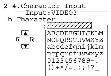
1 Press the [▼] button to select "Character," and then press the [▶] button to display the Character Input screen.
2 Press the [] / [] / [] / [] buttons to select characters you want to enter, and then press the [ENTER] button.
3 Repeat step 2 above to enter up to ten characters.
If you have selected the wrong character: Pressing [RETURN] moves the cursor back to the previous character.
To change a character:
- Press the [ENTER] button (repeatedly) to locate the cursor on the character to be corrected.
- Press the [] / [] buttons to select the new character, and then press the [ENTER] button.
If the name is shorter than ten characters, enter blanks to make the length of the name ten characters.
4 Press the [SETUP] button.
Setup is complete, and the menu screen disappears.
To erase all the characters entered:
At step 1 above, press the [] button instead of the [] button.
IntelliVolume Sub-menu
When multiple devices are connected to the TX-NR1000/TX-NR5000E, the volume may vary for a device even when volume settings on the TX-NR1000/ TX-NR5000E are identical.
Reducing the variance in the volume level will allow you to enjoy sounds at the same volume level without adjusting the volume control on the TX-NR1000/ TX-NR5000E.
IntelliVolume
Use the [] button when the volume is louder than other devices, and the [] button when the volume is quieter.
You can set at 0.5dB intervals within a range from -12.0dB to +12.0dB . The default is 0.0dB .
Delay Sub-menu
This section describes how to adjust the delay of sounds.
A/V Sync
When the picture is not synchronized with the sound, you can synchronize them using these settings. This option can be set for Main B and Zone 2 as well as for Main A.
You can set at 0.1ms intervals within a range from 0.0 ms to 300.0~ms .
Relative Delay - Center, Surr L/R, Surr Back
Our proprietary "Enhanced Special Positioning Algorithm" (an extended three-dimensional positioning algorithm) fine tunes the sound field. This algorithm is able to create a maximum delay of 10ms in the output of each speaker. This delay is equivalent to a distance of about 3 meters between speakers. This option can be set for both Main A and Main B.
- When "Center" is set to "Not Used" on the Speaker Configuration sub-menu, there is no setting for "Center." Likewise, if "Surr L/R" is set to "Not Used," or "Surr Back" is set to "BTL for Front," "Bi-Amp for Front," or "Not Used," there is also no setting for corresponding speakers.
You can set at 0.1ms intervals within a range from -10.0ms to +10.0ms . The default is 0.0ms . Use this function to fine tune your surround environment after setting the distance between speakers (See page 89) and the volume level (See page 90). Extending the distance between speakers (widening the delay in time) will expand the sound field, while reducing the distance (narrowing the delay) will make the sound field sharper.
12V Trigger Assign Sub-menu
When the 12V TRIGGER OUT jack on the TX-NR1000/TX-NR5000E is connected to the12V TRIGGER IN jack of a device, you can specify the room where you are going to trigger the device to turn on the power (for connection details, see page 46). The default settings are as follows:
| Room setting | Delay | |
| Trigger A | Main | 0 |
| Trigger B | Zone 2 | 1 |
| Trigger C | Zone 3 | 2 |
| Trigger D | Off | 0 |
| Trigger E | Main | 2 |
Trigger A-E
The following are settings for the 12V trigger jacks A-E:
Off: Select when not using.
Main: Select when you want to power on a connected device only used in the main room.
Zone 2: Select when you want to power on a connected device only used in Zone 2.
Zone 3: Select when you want to power on a connected device only used in Zone 3.
Main/Zone 2: Select when you want to power on a connected device only used in the main room or Zone 2.
Main/Zone 3: Select when you want to power on a connected device only used in the main room or Zone 3.
Zone 2/Zone 3: Select when you want to power on a connected device only used in Zone 2 or Zone 3.
Main/Zone 2/Zone 3: Select when you want to power on a connected device used in any area: main room, Zone 2, or Zone 3.
A delay-E delay
When a 12V trigger-connected device is powered on, a large amount of current may, depending on the device type, flow instantaneously. To ease the effects of this problem, you can set time interval differences for output signals from the 12V Trigger.
Setting time interval differences may prevent unnecessary noise (bubbling sounds).
0 sec: Select when not setting any difference.
1 sec: Select when setting output signals 1 second after power on to the TX-NR1000/TX-NR5000E.
2 sec: Select when setting output signals 2 seconds after power on to the TX-NR1000/TX-NR5000E.
3 sec: Select when setting output signals 3 seconds after power on to the TX-NR1000/TX-NR5000E.
Listening Mode Setup
This menu allows you to configure the listening mode settings including audio effect and playback options.
Mono Setup Sub-menu
This sub-menu allows you to configure the audio effect and playback options when you play a source in the Mono listening mode.
a. Re-EQ/Academy
This option allows you to configure whether the Re-EQ or Academy effect is applied or not. Use these effects when you do not want to overemphasize the treble sound. This option can also be set for Zone 2.
Off (Default): The effects are not applied.
Re-EQ On: Adjusts the soundtrack in which the treble is overemphasized, so that the sound is optimized for home theater.
Academy On: Lowers the treble level and filters the noise when the source contains emphasized treble sound and too much hiss, such as an old mono audio movie recorded onto videotape.
b. Input Channel
This option configures the output method when you play the stereo input source in the Mono listening mode. This option can also be set for Zone 2.
Auto L + R (Default): The same audio signals are output from the left and right speakers.
Left: When you play an input source with different languages recorded on each channel, the left channel is output from the left and right speakers.
Right: When you play an input source where different languages are recorded on each channel, the right channel is output from the left and right speakers.
c. Output Speaker
This option configures the speakers to use when playing the source in the Mono listening mode. Select the speaker terminals to which the speakers you want to use are connected.
Center A (Default): Outputs the source only from the speaker connected to the CENTER SPEAKERS A terminal.
Center B: Outputs the source only from the speaker connected to the CENTER SPEAKERS B terminal.
Center A+B: Outputs the source from the speakers connected to the CENTER SPEAKERS A and CENTER SPEAKERS B terminals.
Front L/R A: Outputs the source from the speakers connected to the FRONT L/R SPEAKERS A terminals.
Front L/R B: Outputs the source from the speakers connected to the FRONT L/R SPEAKERS B terminals.
Front L/R A+B: Outputs the source from the speakers connected to the FRONT L/R SPEAKERS A and FRONT L/R SPEAKERS B terminals. Note that this option is not available when the front speakers are in Bi-amp or in BTL configuration.
- When the "(Speaker B) Front L/R" is set to an option other than "Main A" in the Speaker Configuration sub-menu, the available options will be "Center A," "Center B," "Center A+B," and "Front L/R A."
- When the "(Speaker A) Center" is set to "Not Used" in the Speaker Configuration sub-menu, the available options will be "Front L/R A," "Front L/R B," and "Front L/R A+B." In this case, the default setting is "Front L/R A."
- When the "(Speaker B) Center" is set to an option other than "Main A" in the Speaker Configuration sub-menu, the available options will be "Center A," "Front L/R A," "Front L/R B," and "Front L/R A+B."
- When the impedance setting for either "Front L/R A" or "Front L/R B" in the Speaker Impedance sub-menu is set to "6 ohms" or "4 ohms," "Front L/R A+B" cannot be selected. Similarly, when the impedance setting for either "Center A" or "Center B" in the Speaker Impedance sub-menu is set to "6 ohms" or "4 ohms," "Center A+B" cannot be selected.
- When the "(Speaker A) Center" is set to "Not Used" and the "(Speaker B) Front L/R" is set to an option other than "Main A" in the Speaker Configuration sub-menu, this setting will not be displayed.
d.Subwoofer
This option configures the subwoofer to use when playing the source in the Mono listening mode. Select the terminal to which the subwoofer you want to use is connected. This setting can be made when the "(Speaker A) Subwoofer" is set to an option other than "Not Used" in the Speaker Configuration sub-menu. However, when the "(Speaker B) Subwoofer" is set to an option other than "Main A" in the Speaker Configuration sub-menu, the available options will be "A" or "Not Used."
A(Default):Outputs the source only from the subwoofer connected to the SUBWOOFER PRE OUT A terminal.
B: Outputs the source only from the subwoofer connected to the SUBWOOFER PRE OUT B terminal.
A+B: Outputs the source from the subwoofoers connected to SUBWOOFER PRE OUT A and SUBWOOFER PRE OUT B terminals.
Not Used: No subwoofoers are used for playback.
Multiplex Setup Sub-menu
This sub-menu allows you to configure the audio effect and playback options when you play a source in the D.F. Multiplex listening mode.
a. Re-EQ/Academy
This option allows you to configure whether the Re-EQ or Academy effect is applied or not. Use these effects when you do not want to overemphasize the treble sound. This option can also be set for Zone 2.
Off (Default): The effects are not applied.
Re-EQ On: Adjusts the soundtrack in which the treble is overemphasized, so that the sound is optimized for home theater.
Academy On: Lowers the treble level and filters the noise when the source contains emphasized treble sound and too much hiss, such as an old mono audio movie recorded onto videotape.
b. Multiplex Input Channel
This option allows you to select the preferred audio channel when the input is the AAC/Dolby Digital sound multiplex signal. This option can also be set for Zone 2. The input channel setting made here will be applied to all the listening modes for the Dolby Digital and AAC input signal "1+1" sources.
Main (Default): The main channel is preferred for output.
Sub: The sub-channel is preferred for output.
Main+Sub: The main and sub-channel are output.
c. Output Speaker
This option configures the speakers to use when playing the source in the D.F. Multiplex listening mode. Select the speaker terminals to which the speakers you want to use are connected.
Center A: Outputs the source only from the speaker connected to the CENTER SPEAKERS A terminal.
Center B: Outputs the source only from the speaker connected to the CENTER SPEAKERS B terminal.
Center A+B: Outputs the source from the speakers connected to the CENTER SPEAKERS A and CENTER SPEAKERS B terminals.
Front L/R A (Default): Outputs the source from the speakers connected to the FRONT L/R SPEAKERS A terminals.
Front L/R B: Outputs the source from the speakers connected to the FRONT L/R SPEAKERS B terminals.
Front L/R A+B: Outputs the source from the speakers connected to the FRONT L/R SPEAKERS A and FRONT L/R SPEAKERS B terminals. Note that this option is not available when the front speakers are in Bi-amp or in BTL configuration.
- When the "(Speaker B) Front L/R" is set to an option other than "Main A" in the Speaker Configuration sub-menu, the available options will be "Center A," "Center B," "Center A+B," and "Front L/R A."
- When the “(Speaker A) Center” is set to “Not Used” in the Speaker Configuration sub-menu, the available options will be “Front L/R A,” “Front L/R B,” and “Front L/R A+B.” In this case, the default setting is “Front L/R A.”
- When the "(Speaker B) Center" is set to an option other than "Main A" in the Speaker Configuration sub-menu, the available options will be "Center A," "Front L/R A," "Front L/R B," and "Front L/R A+B."
- When the impedance setting for either "Front L/R A" or "Front L/R B" in the Speaker Impedance sub-menu is set to "6 ohms" or "4 ohms," "Front L/R A+B"
cannot be selected. Similarly, when the impedance setting for either "Center A" or "Center B" in the Speaker Impedance sub-menu is set to "6 ohms" or "4 ohms," "Center A+B" cannot be selected.
- When the "(Speaker A) Center" is set to "Not Used" and the "(Speaker B) Front L/R" is set to an option other than "Main A" in the Speaker Configuration sub-menu, this setting will not be displayed.
d. Subwoofer
This option configures the subwoofer to use when playing the source in the D.F. Multiplex listening mode. Select the terminal to which the subwoofer you want to use is connected. This setting can be made when the "(Speaker A) Subwoofer" is set to an option other than "Not Used" in the Speaker Configuration sub-menu. However, when the "(Speaker B) Subwoofer" is set to an option other than "Main A" in the Speaker Configuration sub-menu, the available options will be "A" or "Not Used."
A(Default):Outputs the source only from the subwoofer connected to the SUBWOOFER PRE OUT A terminal.
B: Outputs the source only from the subwoofer connected to the SUBWOOFER PRE OUT B terminal.
A+B: Outputs the source from the subwoofoers connected to the SUBWOOFER PRE OUT A and SUBWOOFER PRE OUT B terminals.
Not Used: No subwoofer are used for playback
Stereo Setup Sub-menu
This sub-menu allows you to configure the audio effect and playback options when you play a source in the Stereo listening mode.
a. Re-EQ/Academy
This option allows you to configure whether the Re-EQ or Academy effect is applied or not in the Stereo listening mode. Use these effects when you do not want to overemphasize the treble sound. This option can also be set for Zone 2.
Off (Default): The effects are not applied.
Re-EQ On: Adjusts the soundtrack in which the treble is overemphasized, so that the sound is optimized for home theater.
Academy On: Lowers the treble level and filters the noise when the source contains emphasized treble sound and too much hiss, such as an old mono audio movie recorded onto videotape.
b. Front Speaker
This option configures the speakers to use when playing the source in the Stereo listening mode. Select the speaker terminals to which the speakers you want to use are connected. This setting can be made when the "(Speaker B) Front L/R" is set to "Main A" in the Speaker Configuration sub-menu.
- When the impedance setting for "Front L/R A" or "Front L/R B" in the Speaker Impedance sub-menu is set to "6 ohms" or "4 ohms," the available options will be "A" and "B."
A (Default): Outputs the source from the speakers connected to the FRONT L/R SPEAKERS A terminals.
B: Outputs the source from the speakers connected to the FRONT L/R SPEAKERS B terminals.
A+B: Outputs the source from the speakers connected to the FRONT L/R SPEAKERS A and FRONT L/R SPEAKERS B terminals. Note that this option is not available when the front speakers are in Bi-amp or in BTL configuration.
c.Subwoofer
This option configures the subwoofer to use when playing the source in the Stereo listening mode. Select the terminal to which the subwoofer you want to use is connected. This setting can be made when the "(Speaker A) Subwoofer" is set to an option other than "Not Used" in the Speaker Configuration sub-menu. However, when the "(Speaker B) Subwoofer" is set to an option other than "Main A" in the Speaker Configuration sub-menu, the available options will be "A" or "Not Used."
A(Default):Outputs the source only from the subwoofer connected to the SUBWOOFER PRE OUT A terminal.
B: Outputs the source only from the subwoofer connected to the SUBWOOFER PRE OUT B terminal.
A+B: Outputs the source from the subwoofoers connected to the SUBWOOFER PRE OUT A and SUBWOOFER PRE OUT B terminals.
Not Used: No subwoofer are used for playback.
Direct, Pure Audio Setup Sub-menu
This sub-menu allows you to configure the audio effect and playback options when you play a source in the Direct or Pure Audio listening mode.
a. Front Speaker
This option configures the front speakers to use when playing the source in the Direct or Pure Audio listening mode. Select the speaker terminals to which the speakers you want to use are connected. This setting can be made when the " (Speaker B) Front L/R" is set to "Main A" in the Speaker Configuration sub-menu.
- When the impedance setting for "Front L/R A" or "Front L/R B" in the Speaker Impedance sub-menu is set to "6 ohms" or "4 ohms," the available options will be "A" and "B."
A(Default):Outputs the source from the speakers connected to the FRONT L/R SPEAKERS A terminals. B: Outputs the source from the speakers connected to the FRONT L/R SPEAKERS B terminals.
A+B: Outputs the source from the speakers connected to the FRONT L/R SPEAKERS A and FRONT L/R
SPEAKERS B terminals. Note that this option is not available when the front speakers are in Bi-amp or in BTL configuration.
b. Center Speaker
This option configures the center speaker to use when playing the source in the Direct or Pure Audio listening mode. Select the speaker terminal to which the speaker you want to use is connected. This setting can be made when the “(Speaker B) Center” is set to “Main A” in the Speaker Configuration sub-menu.
- When the impedance setting for "Center A" or "Center B" in the Speaker Impedance sub-menu is set to "6 ohms" or "4 ohms," the available options will be "A" and "B."
A(Default):Outputs the source from the speaker connected to the CENTER SPEAKERS A terminal.
B: Outputs the source from the speaker connected to the CENTER SPEAKERS B terminal.
A+B: Outputs the source from the speakers connected to the CENTER SPEAKERS A and CENTER SPEAKERS B terminals.
c. Surr L/R Sp
This option configures the surround speakers to use when playing the source in the Direct or Pure Audio listening mode. Select the speaker terminals to which the speakers you want to use are connected. This setting can be made when the " (Speaker B) Surr L/R" is set to "Main A" in the Speaker Configuration sub-menu.
- When the impedance setting for "Surr L/R A" or "Surr L/R B" in the Speaker Impedance sub-menu is set to "6 ohms" or "4 ohms," the available options will be "A" and "B."
A (Default): Outputs the source from the speakers connected to the SURR L/R SPEAKERS A terminals.
B: Outputs the source from the speakers connected to the SURR L/R SPEAKERS B terminals.
A+B: Outputs the source from the speakers connected to the SURR L/R SPEAKERS A and SURR L/R SPEAKERS B terminals.
d. Surr Bk Speaker
This option configures the surround back speakers to use when playing the source in the Direct or Pure Audio listening mode. Select the speaker terminals to which the speakers you want to use are connected. This setting can be made when the "(Speaker B) Surr Back" is set to "Main A" in the Speaker Configuration sub-menu. However, when the "(Speaker A) Surr Back" is set to "BTL for Front," "Bi-Amp for Front," or "Not Used," this setting will not be displayed.
-
When the impedance setting for "Surr L/R A" or "Surr L/R B" in the Speaker Impedance sub-menu is set to "6 ohms" or "4 ohms," the available options will be "A" and "B."
-
When the settings for "(Speaker A) Surr Back" and "(Speaker B) Surr Back" in the Speaker Configuration sub-menu differ, the available options will be "A" and "B."
A (Default): Outputs the source from the speakers connected to the SURR BACK L/R SPEAKERS A terminals.
B: Outputs the source from the speakers connected to the SURR BACK L/R SPEAKERS B terminals.
A+B: Outputs the source from the speakers connected to the SURR BACK L/R SPEAKERS A and SURR BACK L/R SPEAKERS B terminals.
e. Subwoofer
This option configures the subwoofer to use when playing the source in the Direct or Pure Audio listening mode. Select the terminal to which the subwoofer you want to use is connected. This setting can be made when the " (Speaker A) Subwoofer" is set to an option other than "Not Used" in the Speaker Configuration sub-menu. However, when the " (Speaker B) Subwoofer" is set to an option other than "Main A" in the Speaker Configuration sub-menu, the available options will be "A" or "Not Used."
A(Default):Outputs the source only from the subwoofer connected to the SUBWOOFER PRE OUT A terminal.
B: Outputs the source only from the subwoofer connected to the SUBWOOFER PRE OUT B terminal.
A+B: Outputs the source from the subwoofoers connected to the SUBWOOFER PRE OUT A and SUBWOOFER PRE OUT B terminals.
Not Used: No subwoofoers are used for playback.
Multichannel Input Setup Sub-menu
This sub-menu allows you to configure the audio effect and playback options when you play an analog multichannel source such as DVD-Audio and Super Audio CD.
a. SB Mode (5ch)
This option selects the enhancement mode for playback when you play a 5.1ch analog multichannel source as a 6.1 or higher channel source through the TX-NR1000/ TX-NR5000E. The surround back setting you select here will be applied to all of the multichannel input signals.
- This option will not appear when the Surr Back Channel setting in the Audio Assign sub-menu is set to "SBL/SBR (7.1ch)."
- When the "(Speaker A) Surr Back" is set to "BTL for Front," "Bi-Amp for Front," or "Not Used" in the Speaker Configuration sub-menu, this option will not be displayed.
Dolby EX: Plays a 5.1ch source as a 6.1 or higher channel source using the Dolby Digital EX mode.
PL IIx Movie (Default): Plays a 5.1ch source as a 6.1 or higher channel source using the Dolby Pro Logic IIx Movie mode.
- When you set the (Speaker A) Surr Back setting to "Main A 1ch (SBL)" in the Speaker Configuration sub-menu, you cannot select "PLIIx Movie."
PL IIx Music: Plays a 5.1ch source as a 6.1 or higher channel source using the Dolby Pro Logic IIx Music mode.
NEO:6: Plays a 5.1ch source as a 6.1 or higher channel source using the DTS NEO:6 mode.
Off: Plays an original 5.1ch source as it is.
b. Re-EQ
This option allows you to configure whether the Re-EQ effect is applied or not when playing an analog multichannel source such as DVD-Audio and Super Audio CD. Use this effect when you do not want to overemphasize the treble sound.
Off (Default): The effect is not applied.
On: Adjusts the soundtrack in which the treble is overemphasized, so that the sound is optimized for home theater.
c. Front Speaker
This option configures the front speakers to use when the TX-NR1000/TX-NR5000E plays an analog multi channel source such as DVD-Audio and Super Audio CD. Select the speaker terminals to which the speakers you want to use are connected. This setting can be made when the "(Speaker B) Front L/R" is set to "Main A" in the Speaker Configuration sub-menu.
- When the impedance setting for "Front L/R A" or "Front L/R B" in the Speaker Impedance sub-menu is set to "6 ohms" or "4 ohms," the available options will be "A" and "B."
A (Default): Outputs the source from the speakers connected to the FRONT L/R SPEAKERS A terminals.
B: Outputs the source from the speakers connected to the FRONT L/R SPEAKERS B terminals.
A+B: Outputs the source from the speakers connected to the FRONT L/R SPEAKERS A and FRONT L/R SPEAKERS B terminals. Note that this option is not available when the front speakers are in Bi-amp or in BTL configuration.
d. Center Speaker
This option configures the center speaker to use when the TX-NR1000/TX-NR5000E plays an analog multichannel source such as DVD-Audio and Super Audio CD. Select the speaker terminal to which the speaker you want to use is connected. This setting can be made when the "(Speaker B) Center" is set to "Main A" in the Speaker Configuration sub-menu.
- When the impedance setting for "Center A" or "Center B" in the Speaker Impedance sub-menu is set to "6 ohms" or "4 ohms," the available options will be "A" and "B."
A (Default): Outputs the source from the speaker connected to the CENTER SPEAKERS A terminal.
B: Outputs the source from the speaker connected to the CENTER SPEAKERS B terminal.
A+B: Outputs the source from the speakers connected to the CENTER SPEAKERS A and CENTER SPEAKERS B terminals.
e. Surr L/R Sp
This option configures the surround speakers to use when the TX-NR1000/TX-NR5000E plays an input source such as DVD-Audio and Super Audio CD. Select the speaker terminals to which the speakers you want to use are connected. This setting can be made when the "Speaker B) Surr L/R" is set to "Main A" in the Speaker Configuration sub-menu.
- When the impedance setting for "Surr L/R A" or "Surr L/R B" in the Speaker Impedance sub-menu is set to "6 ohms" or "4 ohms," the available options will be "A" and "B."
A (Default): Outputs the source from the speakers connected to the SURR L/R SPEAKERS A terminals.
B: Outputs the source from the speakers connected to the SURR L/R SPEAKERS B terminals.
A+B: Outputs the source from the speakers connected to the SURR L/R SPEAKERS A and SURR L/R SPEAKERS B terminals.
f. Surr Bk Speaker
This option configures the surround back speakers to use when the TX-NR1000/TX-NR5000E plays an input source such as DVD-Audio and Super Audio CD. Select the speaker terminals to which the speakers you want to use are connected. This setting can be made when the "(Speaker B) Surr Back" is set to "Main A" in the Speaker Configuration sub-menu. However, when the "(Speaker A) Surr Back" is set to "BTL for Front," "Bi-Amp for Front," or "Not Used," this setting will not be displayed.
- When the impedance setting for "Surr L/R A" or "Surr L/R B" in the Speaker Impedance sub-menu is set to "6 ohms" or "4 ohms," the available options will be "A" and "B."
- When the settings for "(Speaker A) Surr Back" and "(Speaker B) Surr Back" in the Speaker Configuration sub-menu differ, the available options will be "A" and "B."
A (Default): Outputs the source from the speakers connected to the SURR BACK L/R SPEAKERS A terminals.
B: Outputs the source from the speakers connected to the SURR BACK L/R SPEAKERS B terminals.
A+B: Outputs the source from the speakers connected to the SURR BACK L/R SPEAKERS A and SURR BACK L/R SPEAKERS B terminals.
g.Subwoofer
This option configures the subwoofer to use when the TX-NR1000/TX-NR5000E plays an input source such as DVD-Audio and Super Audio CD. Select the terminal to which the subwoofer you want to use is connected. This setting can be made when the "(Speaker A) Subwoofer" is set to an option other than "Not Used" in the Speaker Configuration sub-menu. However, when the "(Speaker B) Subwoofer" is set to an option other than "Main A" in the Speaker Configuration sub-menu, the available options will be "A" or "Not Used."
A(Default):Outputs the source only from the subwoofer connected to the SUBWOOFER PRE OUT A terminal.
B: Outputs the source only from the subwoofer connected to the SUBWOOFER PRE OUT B terminal.
A+B: Outputs the source from the subwoofoers connected to the SUBWOOFER PRE OUT A and SUBWOOFER PRE OUT B terminals.
Not Used: No subwoofoers are used for playback.
i.LINK(IEEE1394):DVD-Audio Input Setup Sub-menu
This sub-menu allows you to configure the audio effect and playback options when you play DVD-Audio that is input from the i.LINK (AUDIO) interface.
a. LFE Level
This option allows you to set the bass level for the i.LINK(IEEE1394):DVD-Audio listening mode. The LFE level setting made here will be applied to all of the i.LINK(IEEE1394):DVD-Audio input signals. The available settings are - dB, -20 dB, -10 dB, and 0 dB. The option defaults to "0."
b. SB Mode (5ch)
Selects the enhancement mode for playback when you play a 5.1ch source as a 6.1 or higher channel source through the TX-NR1000/TX-NR5000E. The surround back setting you select here will be applied to the i.LINK(IEEE1394):DVD-Audio input signal * / 2
- When the "(Speaker A) Surr Back" is set to "BTL for Front," "Bi-Amp for Front," or "Not Used" in the Speaker Configuration sub-menu, this option will not be displayed.
Dolby EX: Plays a 5.1ch source as a 6.1 or higher channel source using the Dolby Digital EX mode.
PLIIx Movie: Plays a 5.1ch source as a 6.1 or higher channel source using the Dolby Pro Logic IIx Movie mode. - When you set the (Speaker A) Surr Back setting to "Main A 1ch (SBL)" in the Speaker Configuration sub-menu, you cannot select "PLIIx Movie."
PLIIx Music: Plays a 5.1ch source as a 6.1 or higher channel source using the Dolby Pro Logic IIx Music mode.
NEO:6: Plays a 5.1ch source as a 6.1 or higher channel source using the DTS NEO:6 mode.
Off(Default):Plays an original 5.1ch source as it is.
c. Re-EQ
This option allows you to configure whether the Re-EQ effect is applied or not. Use this effect when you do not want to overemphasize the treble sound.
Off (Default): The effect is not applied.
On: Adjusts the soundtrack in which the treble is overemphasized, so that the sound is optimized for home theater.
d. Front Speaker
This option configures the front speakers to use when the TX-NR1000/TX-NR5000E plays DVD-Audio. Select the speaker terminals to which the speakers you want to use are connected. This setting can be made when the “(Speaker B) Front L/R” is set to “Main A” in the Speaker Configuration sub-menu.
- When the impedance setting for "Front L/R A" or "Front L/R B" in the Speaker Impedance sub-menu is set to "6 ohms" or "4 ohms," the available options will be "A" and "B."
A(Default):Outputs the source from the speakers connected to the FRONT L/R SPEAKERS A terminals.
B: Outputs the source from the speakers connected to the FRONT L/R SPEAKERS B terminals.
A+B: Outputs the source from the speakers connected to the FRONT L/R SPEAKERS A and FRONT L/R SPEAKERS B terminals. Note that this option is not available when the front speakers are in Bi-amp or in BTL configuration.
e. Center Speaker
This option configures the center speaker to use when the TX-NR1000/TX-NR5000E plays DVD-Audio. Select the speaker terminal to which the speaker you want to use is connected. This setting can be made when the "(Speaker B) Center" is set to "Main A" in the Speaker Configuration sub-menu.
- When the impedance setting for "Center A" or "Center B" in the Speaker Impedance sub-menu is set to "6 ohms" or "4 ohms," the available options will be "A" and "B."
A (Default): Outputs the source from the speaker connected to the CENTER SPEAKERS A terminal.
B: Outputs the source from the speaker connected to the CENTER SPEAKERS B terminal.
A+B: Outputs the source from the speakers connected to the CENTER SPEAKERS A and CENTER SPEAKERS B terminals.
f. Surr L/R Sp
This option configures the surround speakers to use when the TX-NR1000/TX-NR5000E plays DVD-
Audio. Select the speaker terminals to which the speakers you want to use are connected. This setting can be made when the "(Speaker B) Surr L/R" is set to "Main A" in the Speaker Configuration sub-menu.
- When the impedance setting for "Surr L/R A" or "Surr L/R B" in the Speaker Impedance sub-menu is set to "6 ohms" or "4 ohms," the available options will be "A" and "B."
A (Default): Outputs the source from the speakers connected to the SURL/R SPEAKERS A terminals.
B: Outputs the source from the speakers connected to the SURR L/R SPEAKERS B terminals.
A+B: Outputs the source from the speakers connected to the SURR L/R SPEAKERS A and SURR L/R SPEAKERS B terminals.
g. Surr Bk Speaker
This option configures the surround back speakers to use when the TX-NR1000/TX-NR5000E plays DVD-Audio. Select the speaker terminals to which the speakers you want to use are connected. This setting can be made when the "(Speaker B) Surr Back" is set to "Main A" in the Speaker Configuration sub-menu. However, when the "(Speaker A) Surr Back" is set to "BTL for Front," "Bi-Amp for Front," or "Not Used," this setting will not be displayed.
- When the impedance setting for "Surr L/R A" or "Surr L/R B" in the Speaker Impedance sub-menu is set to "6 ohms" or "4 ohms," the available options will be "A" and "B."
- When the settings for “(Speaker A) Surr Back” and “(Speaker B) Surr Back” in the Speaker Configuration sub-menu differ, the available options will be “A” and “B.”
A(Default):Outputs the source from the speakers connected to the SURR BACK L/R SPEAKERS A terminals.
B: Outputs the source from the speakers connected to the SURR BACK L/R SPEAKERS B terminals.
A+B: Outputs the source from the speakers connected to the SURR BACK L/R SPEAKERS A and SURR BACK L/R SPEAKERS B terminals.
h.Subwoofer
This option configures the subwoofer to use when the TX-NR1000/TX-NR5000E plays DVD-Audio. Select the terminal to which the subwoofer you want to use is connected. This setting can be made when the "(Speaker A) Subwoofer" is set to an option other than "Not Used" in the Speaker Configuration sub-menu. However, when the "(Speaker B) Subwoofer" is set to an option other than "Main A" in the Speaker Configuration sub-menu, the available options will be "A" or "Not Used."
A(Default):Outputs the source only from the subwoofer connected to the SUBWOOFER PRE OUT A terminal.
B: Outputs the source only from the subwoofer connected to the SUBWOOFER PRE OUT B terminal.
A+B: Outputs the source from the subwoofoers connected to the SUBWOOFER PRE OUT A and SUBWOOFER PRE OUT B terminals.
Not Used: No subwoofer are used for playback.
i.LINK(IEEE1394):SACD Input Setup Sub-menu
This sub-menu allows you to configure the audio effect and playback options when you play a Super Audio CD input from the i.LINK (AUDIO) interface.
a. LFE Level
This option allows you to set the bass level for the i.LINK(IEEE1394):SACD listening mode. The LFE level setting made here will be applied to all of the i.LINK(IEEE1394):SACD input signals. The available settings are - dB, -20 dB, -10 dB, and 0 dB. The option defaults to "0."
b. SB Mode (5ch)
Selects the enhancement mode for playback when you play a 5.1ch source as a 6.1 or higher channel source through the TX-NR1000/TX-NR5000E. The surround back setting you select here will be applied to the i.LINK(IEEE1394):SACD input signal “*/2.”
- When the "(Speaker A) Surr Back" is set to "BTL for Front," "Bi-Amp for Front," or "Not Used" in the Speaker Configuration sub-menu, this option will not be displayed.
Dolby EX: Plays a 5.1ch source as a 6.1 or higher channel source using the Dolby Digital EX mode.
PLIIx Movie: Plays a 5.1ch source as a 6.1 or higher channel source using the Dolby Pro Logic IIx Movie mode.
- When you set the (Speaker A) Surr Back setting to "Main A 1ch (SBL)" in the Speaker Configuration sub-menu, you cannot select "PLIIx Movie."
PLIIx Music: Plays a 5.1ch source as a 6.1 or higher channel source using the Dolby Pro Logic IIx Music mode.
NEO:6: Plays a 5.1ch source as a 6.1 or higher channel source using the DTS NEO:6 mode.
Off(Default):Plays an original 5.1ch source as it is.
c. Re-EQ
This option allows you to configure whether the Re-EQ effect is applied or not. Use this effect when you do not want to overemphasize the treble sound.
Off (Default): The effect is not applied.
On: Adjusts the soundtrack in which the treble is overemphasized, so that the sound is optimized for home theater.
d. Front Speaker
This option configures the front speakers to use when the TX-NR1000/TX-NR5000E plays a Super Audio CD. Select the speaker terminals to which the speakers
you want to use are connected. This setting can be made when the " (Speaker B) Front L/R" is set to "Main A" in the Speaker Configuration sub-menu.
- When the impedance setting for "Front L/R A" or "Front L/R B" in the Speaker Impedance sub-menu is set to "6 ohms" or "4 ohms," the available options will be "A" and "B."
A(Default):Outputs the source from the speakers connected to the FRONT L/R SPEAKERS A terminals.
B: Outputs the source from the speakers connected to the FRONT L/R SPEAKERS B terminals.
A+B: Outputs the source from the speakers connected to the FRONT L/R SPEAKERS A and FRONT L/R SPEAKERS B terminals. Note that this option is not available when the front speakers are in Bi-amp or in BTL configuration.
e. Center Speaker
This option configures the center speaker to use when the TX-NR1000/TX-NR5000E plays a Super Audio CD. Select the speaker terminal to which the speaker you want to use is connected. This setting can be made when the " (Speaker B) Center" is set to "Main A" in the Speaker Configuration sub-menu.
- When the impedance setting for "Center A" or "Center B" in the Speaker Impedance sub-menu is set to "6 ohms" or "4 ohms," the available options will be "A" and "B."
A (Default): Outputs the source from the speaker connected to the CENTER SPEAKERS A terminal.
B: Outputs the source from the speaker connected to the CENTER SPEAKERS B terminal.
A+B: Outputs the source from the speakers connected to the CENTER SPEAKERS A and CENTER SPEAKERS B terminals.
f. Surr L/R Sp
This option configures the surround speakers to use when the TX-NR1000/TX-NR5000E plays a Super Audio CD. Select the speaker terminals to which the speakers you want to use are connected. This setting can be made when the "(Speaker B) Surr L/R" is set to "Main A" in the Speaker Configuration sub-menu.
- When the impedance setting for "Surr L/R A" or "Surr L/R B" in the Speaker Impedance sub-menu is set to "6 ohms" or "4 ohms," the available options will be "A" and "B."
A (Default): Outputs the source from the speakers connected to the SURR L/R SPEAKERS A terminals.
B: Outputs the source from the speakers connected to the SURR L/R SPEAKERS B terminals.
A+B: Outputs the source from the speakers connected to the SURR L/R SPEAKERS A and SURR L/R SPEAKERS B terminals.
g. Surr Bk Speaker
This option configures the surround back speakers to use when the TX-NR1000/TX-NR5000E plays a Super Audio CD. Select the speaker terminals to which the speakers you want to use are connected. This setting can be made when the "(Speaker B) Surr Back" is set to "Main A" in the Speaker Configuration sub-menu. However, when the "(Speaker A) Surr Back" is set to "BTL for Front," "Bi-Amp for Front," or "Not Used," this setting will not be displayed.
- When the impedance setting for "Surr L/R A" or "Surr L/R B" in the Speaker Impedance sub-menu is set to "6 ohms" or "4 ohms," the available options will be "A" and "B."
- When the settings for "(Speaker A) Surr Back" and "(Speaker B) Surr Back" in the Speaker Configuration sub-menu differ, the available options will be "A" and "B."
A (Default): Outputs the source from the speakers connected to the SURR BACK L/R SPEAKERS A terminals.
B: Outputs the source from the speakers connected to the SURR BACK L/R SPEAKERS B terminals.
A+B: Outputs the source from the speakers connected to the SURR BACK L/R SPEAKERS A and SURR BACK L/R SPEAKERS B terminals.
h.Subwoofer
This option configures the subwoofer to use when the TX-NR1000/TX-NR5000E plays a Super Audio CD. Select the terminal to which the subwoofer you want to use is connected. This setting can be made when the "(Speaker A) Subwoofer" is set to an option other than "Not Used" in the Speaker Configuration sub-menu. However, when the "(Speaker B) Subwoofer" is set to an option other than "Main A" in the Speaker Configuration sub-menu, the available options will be "A" or "Not Used."
A(Default):Outputs the source only from the subwoofer connected to the SUBWOOFER PRE OUT A terminal.
B: Outputs the source only from the subwoofer connected to the SUBWOOFER PRE OUT B terminal.
A+B: Outputs the source from the subwoofoers connected to the SUBWOOFER PRE OUT A and SUBWOOFER PRE OUT B terminals.
Not Used: No subwoofoers are used for playback.
Dolby Digital Setup Sub-menu
This sub-menu allows you to configure the audio effect and playback options when you play a source in the Dolby Digital listening mode.
a. LFE Level
This option allows you to set the bass level for the Dolby Digital listening mode. The LFE level setting made here will be applied to all of the Dolby Digital input signals.
The available settings are - dB, -20 dB, -10 dB, and 0 dB. The option defaults to "0." This option can also be set for Zone 2.
b. Late Night
This option allows you to set how the Late Night function works (See page 55). The setting you select here will be applied to all of the Dolby Digital input signals. Note that the Late Night setting will not be retained and will return to "Off" after the TX-NR1000/ TX-NR5000E enters the standby state. This option can also be set for Zone 2.
Off: Disables the Late Night function.
Low: Narrows the volume range.
High: Narrows the volume range more than the "Low" setting.
c. Dolby EX
This option configures the Dolby EX effect when playing the source in the Dolby Digital listening mode. Auto: Automatically plays a source using the Dolby EX mode when the source contains the Dolby Digital EX identification signal. When this signal is not contained, the setting of "SB Mode (5ch)" is applied.
Manual: The setting of "SB Mode (5ch)" is applied regardless of the Dolby Digital EX identification signal.
d. SB Mode (5ch)
This option allows you to select the enhancement mode for playback when you play a 5.1ch source as a 6.1 or higher channel source through the TX-NR1000/ TX-NR5000E. The surround back setting you select here will be applied to the Dolby Digital input signal * / 2
- When the "(Speaker A) Surr Back" is set to "BTL for Front," "Bi-Amp for Front," or "Not Used" in the Speaker Configuration sub-menu, this option will not be displayed.
Dolby EX: Plays a 5.1ch source as a 6.1 or higher channel source using the Dolby Digital EX mode.
PLIIx Movie (Default): Plays a 5.1ch source as a 6.1 or higher channel source using the Dolby Pro Logic IIx Movie mode.
- When you set the (Speaker A) Surr Back setting to "Main A 1ch (SBL)" in the Speaker Configuration sub-menu, you cannot select "PLIIx Movie."
PLIIx Music: Plays a 5.1ch source as a 6.1 or higher channel source using the Dolby Pro Logic IIx Music mode.
NEO:6: Plays a 5.1ch source as a 6.1 or higher channel source using the DTS NEO:6 mode.
Off: Plays an original 5.1ch source as it is.
e. Re-EQ
This option allows you to configure whether the Re-EQ effect is applied or not. Use this effect when you do not want to overemphasize the treble sound.
Off (Default): The effect is not applied.
On: Adjusts the soundtrack in which the treble is overemphasized, so that the sound is optimized for home theater.
f. Front Speaker
This option configures the front speakers to use when playing the source in the Dolby Digital listening mode. Select the speaker terminals to which the speakers you want to use are connected. This setting can be made when the " (Speaker B) Front L/R" is set to "Main A" in the Speaker Configuration sub-menu.
- When the impedance setting for "Front L/R A" or "Front L/R B" in the Speaker Impedance sub-menu is set to "6 ohms" or "4 ohms," the available options will be "A" and "B."
A(Default):Outputs the source from the speakers connected to the FRONT L/R SPEAKERS A terminals.
B: Outputs the source from the speakers connected to the FRONT L/R SPEAKERS B terminals.
A+B: Outputs the source from the speakers connected to the FRONT L/R SPEAKERS A and FRONT L/R SPEAKERS B terminals. Note that this option is not available when the front speakers are in Bi-amp or in BTL configuration.
g. Center Speaker
This option configures the center speaker to use when playing the source in the Dolby Digital listening mode. Select the speaker terminal to which the speaker you want to use is connected. This setting can be made when the "(Speaker B) Center" is set to "Main A" in the Speaker Configuration sub-menu.
- When the impedance setting for "Center A" or "Center B" in the Speaker Impedance sub-menu is set to "6 ohms" or "4 ohms," the available options will be "A" and "B."
A(Default):Outputs the source from the speaker connected to the CENTER SPEAKERS A terminal.
B: Outputs the source from the speaker connected to the CENTER SPEAKERS B terminal.
A+B: Outputs the source from the speakers connected to the CENTER SPEAKERS A and CENTER SPEAKERS B terminals.
h. Surr L/R Sp
This option configures the surround speakers to use when playing the source in the Dolby Digital listening mode. Select the speaker terminals to which the speakers you want to use are connected. This setting can be made when the " (Speaker B) Surr L/R" is set to "Main A" in the Speaker Configuration sub-menu.
- When the impedance setting for "Surr L/R A" or "Surr L/R B" in the Speaker Impedance sub-menu is set to "6 ohms" or "4 ohms," the available options will be "A" and "B."
A (Default): Outputs the source from the speakers connected to the SURR L/R SPEAKERS A terminals.
B: Outputs the source from the speakers connected to the SARR L/R SPEAKERS B terminals.
A+B: Outputs the source from the speakers connected to the SURR L/R SPEAKERS A and SURR L/R SPEAKERS B terminals.
i. Surr Bk Speaker
This option configures the surround back speakers to use when playing the source in the Dolby Digital listening mode. Select the speaker terminals to which the speakers you want to use are connected. This setting can be made when the "(Speaker B) Surr Back" is set to "Main A" in the Speaker Configuration sub-menu. However, when the "(Speaker A) Surr Back" is set to "BTL for Front," "Bi-Amp for Front," or "Not Used," this setting will not be displayed.
- When the impedance setting for "Surr L/R A" or "Surr L/R B" in the Speaker Impedance sub-menu is set to "6 ohms" or "4 ohms," the available options will be "A" and "B."
- When the settings for "(Speaker A) Surr Back" and "(Speaker B) Surr Back" in the Speaker Configuration sub-menu differ, the available options will be "A" and "B."
A (Default): Outputs the source from the speakers connected to the SURR BACK L/R SPEAKERS A terminals.
B: Outputs the source from the speakers connected to the SURR BACK L/R SPEAKERS B terminals.
A+B: Outputs the source from the speakers connected to the SURR BACK L/R SPEAKERS A and SURR BACK L/R SPEAKERS B terminals.
j.Subwoofer
This option configures the subwoofer to use when playing the source in the Dolby Digital listening mode. Select the terminal to which the subwoofer you want to use is connected. This setting can be made when the "(Speaker A) Subwoofer" is set to an option other than "Not Used" in the Speaker Configuration sub-menu. However, when the "(Speaker B) Subwoofer" is set to an option other than "Main A" in the Speaker Configuration sub-menu, the available options will be "A" or "Not Used."
A(Default):Outputs the source only from the subwoofer connected to the SUBWOOFER PRE OUT A terminal.
B: Outputs the source only from the subwoofer connected to the SUBWOOFER PRE OUT B terminal.
A+B: Outputs the source from the subwoofoers connected to the SUBWOOFER PRE OUT A and SUBWOOFER PRE OUT B terminals.
Not Used: No subwoofoers are used for playback.
DTS Setup Sub-menu
This sub-menu allows you to configure the audio effect and playback options when you play a source in the DTS listening mode.
a. LFE Level
This option allows you to set the bass level for the DTS listening mode. The LFE level setting made here will be applied to all of the DTS input signals. The available settings are - dB, -20 dB, -10 dB, and 0 dB. The option defaults to "0." This option can also be set for Zone 2.
b. SB Mode (5ch)
This option allows you to select the enhancement mode for playback when you play a 5.1ch source as a 6.1 or higher channel source through the TX-NR1000/ TX-NR5000E. The surround back setting you select here will be applied to the DTS input signal * / 2
- When the "(Speaker A) Surr Back" is set to "BTL for Front," "Bi-Amp for Front," or "Not Used" in the Speaker Configuration sub-menu, this option will not be displayed.
NEO:6: Plays a 5.1ch source as a 6.1 or higher channel source using the DTS NEO:6 mode.
Dolby EX: Plays a 5.1ch source as a 6.1 or higher channel source using the Dolby Digital EX mode.
PLIIx Movie: Plays a 5.1ch source as a 6.1 or higher channel source using the Dolby Pro Logic IIx Movie mode.
- When you set the (Speaker A) Surr Back setting to "Main A 1ch (SBL)" in the Speaker Configuration sub-menu, you cannot select "PLIIx Movie."
PLIIx Music: Plays a 5.1ch source as a 6.1 or higher channel source using the Dolby Pro Logic IIx Music mode.
Off: Plays an original 5.1ch source as it is.
c. Re-EQ
This option allows you to configure whether the Re-EQ effect is applied or not. Use this effect when you do not want to overemphasize the treble sound.
Off (Default): The effect is not applied.
On: Adjusts the soundtrack in which the treble is overemphasized, so that the sound is optimized for home theater.
d. Front Speaker
This option configures the front speakers to use when playing the source in the DTS listening mode. Select the speaker terminals to which the speakers you want to use are connected. This setting can be made when the "(Speaker B) Front L/R" is set to "Main A" in the Speaker Configuration sub-menu.
- When the impedance setting for "Front L/R A" or "Front L/R B" in the Speaker Impedance sub-menu is
set to "6 ohms" or "4 ohms," the available options will be "A" and "B."
A(Default):Outputs the source from the speakers connected to the FRONT L/R SPEAKERS A terminals.
B: Outputs the source from the speakers connected to the FRONT L/R SPEAKERS B terminals.
A+B: Outputs the source from the speakers connected to the FRONT L/R SPEAKERS A and FRONT L/R SPEAKERS B terminals. Note that this option is not available when the front speakers are in Bi-amp or in BTL configuration.
e. Center Speaker
This option configures the center speaker to use when playing the source in the DTS listening mode. Select the speaker terminal to which the speaker you want to use is connected. This setting can be made when the " (Speaker B) Center" is set to "Main A" in the Speaker Configuration sub-menu.
- When the impedance setting for "Center A" or "Center B" in the Speaker Impedance sub-menu is set to "6 ohms" or "4 ohms," the available options will be "A" and "B."
A (Default): Outputs the source from the speaker connected to the CENTER SPEAKERS A terminal.
B: Outputs the source from the speaker connected to the CENTER SPEAKERS B terminal.
A+B: Outputs the source from the speakers connected to the CENTER SPEAKERS A and CENTER SPEAKERS B terminals.
f. Surr L/R Sp
This option configures the surround speakers to use when playing the source in the DTS listening mode. Select the speaker terminals to which the speakers you want to use are connected. This setting can be made when the " (Speaker B) Surr L/R" is set to "Main A" in the Speaker Configuration sub-menu.
- When the impedance setting for "Surr L/R A" or "Surr L/R B" in the Speaker Impedance sub-menu is set to "6 ohms" or "4 ohms," the available options will be "A" and "B."
A(Default):Outputs the source from the speakers connected to the SURL/R SPEAKERS A terminals.
B: Outputs the source from the speakers connected to the SURR L/R SPEAKERS B terminals.
A+B: Outputs the source from the speakers connected to the SURR L/R SPEAKERS A and SURR L/R SPEAKERS B terminals.
g. Surr Bk Speaker
This option configures the surround back speakers to use when playing the source in the DTS listening mode. Select the speaker terminals to which the speakers you want to use are connected. This setting can be made when the " (Speaker B) Surr Back" is set to "Main A" in the Speaker Configuration sub-menu. However, when the "(Speaker A) Surr Back" is set to "BTL for Front," "Bi-Amp for Front," or "Not Used," this setting will not be displayed.
- When the impedance setting for "Surr L/R A" or "Surr L/R B" in the Speaker Impedance sub-menu is set to "6 ohms" or "4 ohms," the available options will be "A" and "B."
- When the settings for “(Speaker A) Surr Back” and “(Speaker B) Surr Back” in the Speaker Configuration sub-menu differ, the available options will be “A” and “B.”
A (Default): Outputs the source from the speakers connected to the SURR BACK L/R SPEAKERS A terminals.
B: Outputs the source from the speakers connected to the SURR BACK L/R SPEAKERS B terminals.
A+B: Outputs the source from the speakers connected to the SURR BACK L/R SPEAKERS A and SURR BACK L/R SPEAKERS B terminals.
h.Subwoofer
This option configures the subwoofer to use when playing the source in the DTS listening mode. Select the terminal to which the subwoofer you want to use is connected. This setting can be made when the "(Speaker A) Subwoofer" is set to an option other than "Not Used" in the Speaker Configuration sub-menu. However, when the "(Speaker B) Subwoofer" is set to an option other than "Main A" in the Speaker Configuration sub-menu, the available options will be "A" or "Not Used."
A(Default):Outputs the source only from the subwoofer connected to the SUBWOOFER PRE OUT A terminal.
B: Outputs the source only from the subwoofer connected to the SUBWOOFER PRE OUT B terminal.
A+B: Outputs the source from the subwoofoers connected to the SUBWOOFER PRE OUT A and SUBWOOFER PRE OUT B terminals.
Not Used: No subwoofer are used for playback.
AAC Setup Sub-menu
This sub-menu allows you to configure the audio effect and playback options when you play a source in the AAC listening mode.
a. LFE Level
This option allows you to set the bass level for the AAC listening mode. The LFE level setting made here will be applied to all of the AAC input signals. The available
settings are - dB, -20 dB, -10 dB, and 0 dB. The option defaults to "0." This option can also be set for Zone 2.
b. SB Mode (5ch)
Selects the enhancement mode for playback when you play a 5.1ch source as a 6.1 or higher channel source through the TX-NR1000/TX-NR5000E. The surround back setting you select here will be applied to the AAC input signal * / 2
- When the "(Speaker A) Surr Back" is set to "BTL for Front," "Bi-Amp for Front," or "Not Used" in the Speaker Configuration sub-menu, this option will not be displayed.
Dolby EX: Plays a 5.1ch source as a 6.1 or higher channel source using the Dolby Digital EX mode.
PLIIx Movie (Default): Plays a 5.1ch source as a 6.1 or higher channel source using the Dolby Pro Logic IIx Movie mode.
- When you set the (Speaker A) Surr Back setting to "Main A 1ch (SBL)" in the Speaker Configuration sub-menu, you cannot select "PLIIx Movie."
PLIIx Music: Plays a 5.1ch source as a 6.1 or higher channel source using the Dolby Pro Logic IIx Music mode.
NEO:6: Plays a 5.1ch source as a 6.1 or higher channel source using the DTS NEO:6 mode.
Off: Plays an original 5.1ch source as it is.
c. Re-EQ
This option allows you to configure whether the Re-EQ effect is applied or not. Use this effect when you do not want to overemphasize the treble sound.
Off (Default): The effect is not applied.
On: Adjusts the soundtrack in which the treble is overemphasized, so that the sound is optimized for home theater.
d. Front Speaker
This option configures the front speakers to use when playing the source in the AAC listening mode. Select the speaker terminals to which the speakers you want to use are connected. This setting can be made when the " (Speaker B) Front L/R" is set to "Main A" in the Speaker Configuration sub-menu.
- When the impedance setting for "Front L/R A" or "Front L/R B" in the Speaker Impedance sub-menu is set to "6 ohms" or "4 ohms," the available options will be "A" and "B."
A (Default): Outputs the source from the speakers connected to the FRONT L/R SPEAKERS A terminals.
B: Outputs the source from the speakers connected to the FRONT L/R SPEAKERS B terminals.
A+B: Outputs the source from the speakers connected to the FRONT L/R SPEAKERS A and FRONT L/R SPEAKERS B terminals. Note that this option is not available when the front speakers are in Bi-amp or in BTL configuration.
e. Center Speaker
This option configures the center speaker to use when playing the source in the AAC listening mode. Select the speaker terminal to which the speaker you want to use is connected. This setting can be made when the "(Speaker B) Center" is set to "Main A" in the Speaker Configuration sub-menu.
- When the impedance setting for "Center A" or "Center B" in the Speaker Impedance sub-menu is set to "6 ohms" or "4 ohms," the available options will be "A" and "B."
A(Default):Outputs the source from the speaker connected to the CENTER SPEAKERS A terminal.
B: Outputs the source from the speaker connected to the CENTER SPEAKERS B terminal.
A+B: Outputs the source from the speakers connected to the CENTER SPEAKERS A and CENTER SPEAKERS B terminals.
f. Surr L/R Sp
This option configures the surround speakers to use when playing the source in the AAC listening mode. Select the speaker terminals to which the speakers you want to use are connected. This setting can be made when the "(Speaker B) Surr L/R" is set to "Main A" in the Speaker Configuration sub-menu.
- When the impedance setting for "Surr L/R A" or "Surr L/R B" in the Speaker Impedance sub-menu is set to "6 ohms" or "4 ohms," the available options will be "A" and "B."
A(Default):Outputs the source from the speakers connected to the SURL/R SPEAKERS A terminals.
B: Outputs the source from the speakers connected to the SURR L/R SPEAKERS B terminals.
A+B: Outputs the source from the speakers connected to the SURR L/R SPEAKERS A and SURR L/R SPEAKERS B terminals.
g. Surr Bk Speaker
This option configures the surround back speakers to use when playing the source in the AAC listening mode. Select the speaker terminals to which the speakers you want to use are connected. This setting can be made when the " (Speaker B) Surr Back" is set to "Main A" in the Speaker Configuration sub-menu. However, when the "(Speaker A) Surr Back" is set to "BTL for Front," "Bi-Amp for Front," or "Not Used," this setting will not be displayed.
- When the impedance setting for "Surr L/R A" or "Surr L/R B" in the Speaker Impedance sub-menu is set to "6 ohms" or "4 ohms," the available options will be "A" and B.
- When the settings for “(Speaker A) Surr Back” and “(Speaker B) Surr Back” in the Speaker Configuration sub-menu differ, the available options will be “A” and “B.”
A(Default):Outputs the source from the speakers connected to the SURR BACK L/R SPEAKERS A terminals.
B: Outputs the source from the speakers connected to the SURR BACK L/R SPEAKERS B terminals.
A+B: Outputs the source from the speakers connected to the SURR BACK L/R SPEAKERS A and SURR BACK L/R SPEAKERS B terminals.
h.Subwoofer
This option configures the subwoofer to use when playing the source in the AAC listening mode. Select the terminal to which the subwoofer you want to use is connected. This setting can be made when the "(Speaker A) Subwoofer" is set to an option other than "Not Used" in the Speaker Configuration sub-menu. However, when the "(Speaker B) Subwoofer" is set to an option other than "Main A" in the Speaker Configuration sub-menu, the available options will be "A" or "Not Used."
A(Default):Outputs the source only from the subwoofer connected to the SUBWOOFER PRE OUT A terminal.
B: Outputs the source only from the subwoofer connected to the SUBWOOFER PRE OUT B terminal.
A+B: Outputs the source from the subwoofoers connected to the SUBWOOFER PRE OUT A and SUBWOOFER PRE OUT B terminals.
Not Used: No subwoofoers are used for playback.
Dolby Pro Logic IIx/DTS NEO:6 (2ch Input only) Setup Sub-menu
This sub-menu allows you to configure the audio effect and playback options when you play a 2ch input source in the Dolby Pro Logic IIx or DTS NEO:6 listening modes. This setting can be made when the "(Speaker A) Center" or "(Speaker A) Surr Back" setting is set to an option other than "Not Used" in the Speaker Configuration sub-menu.
- When the "(Speaker A) Surr Back" is set to "BTL for Front," "Bi-Amp for Front" or "Not Used," the PLII mode will be used instead of the PLIIx mode.
a. Surr Mode (2ch)
Selects the enhancement mode for playback when you play a 2ch source as a 6.1 or higher channel source through the TX-NR1000/TX-NR5000E. The surround mode setting you select here will be applied to the Analog/PCM and D.F. 2ch input signals.
- The option "NEO:6 Music" will be available when the (Speaker A) Surr Back setting is set to "Main A" in the Speaker Configuration sub-menu.
PLIIx Movie (Default): Plays a 2ch source as a 6.1 or higher channel source using the Dolby Pro Logic IIx Movie mode.
PLIIx Music: Plays a 2ch source as a 6.1 or higher channel source using the Dolby Pro Logic IIx Music mode.
PLIIx Game: Plays a 2ch source as a 6.1 or higher channel source using the Dolby Pro Logic IIx Game mode.
NEO:6 Cinema: Plays a 2ch source as a 6.1 or higher channel source using the DTS NEO:6NEO:6 Cinema mode.
NEO:6 Music: Plays a 2ch source as a 6.1 or higher channel source using the DTS NEO:6 Music mode.
b. PLIIx Music Panorama
This option allows you to configure the panorama effect during the Dolby Pro Logic IIx Music mode. This effect will expand the sound space horizontally.
On: The panorama effect is turned on.
Off (Default): The panorama effect is turned off.
c. PLIIx Music Dimension
This option allows you to change the entire sound space location either forward or backward during the Dolby Pro Logic IIx Music mode. The option defaults to "3." The value "3" locates the sound space to the center position. If you select values between "2" and "0," the sound space moves forward. If you select values between "4" and "6," the sound space moves backward.
Tips:
When you feel the sound space is too expanded or that there is too much surround effect, move the sound space forward to obtain a better balance. When you feel the sound space is just like a mono source or is too narrow, move the sound space backward to obtain a better balance.
d. PLIIx Music Center Width
This option allows you to adjust the sound image width which the center speaker covers during the Dolby Pro Logic IIx Music mode. When you play the source in the Dolby Pro Logic II mode and the center speaker is connected to the TX-NR1000/TX-NR5000E, the center channel signal is output only from the center speaker (if the center speaker is not connected, the center channel signal will be equally divided into the left and right front speakers to create a virtual center sound image). In this option, adjust the output balance between the center and front left/right speakers to determine the scale for the central sound image. The available settings for this option are between "0" and "7." The default value is "3."
e. NEO:6 Music Center Image
This setting can be made when the (Speaker A) Surr Back setting is set to "Main A" in the Speaker Configuration sub-menu.
The DTS NEO:6 Music mode is a listening mode in which an original 2ch source is played as a 6ch source. In this mode, the signal for center channel will be created from the signals deducted to some extent from the left and right front channels. This option allows you to configure how much the signals are deducted from the left and right channels to produce the center channel
image. The available settings for this option are between "0" and "5." The default value is "2."
f. Re-EQ
This option allows you to configure whether the Re-EQ effect is applied or not. Use this effect when you do not want to overemphasize the treble sound.
Off (Default): The effect is not applied.
On: Adjusts the soundtrack in which the treble is overemphasized, so that the sound is optimized for home theater.
g. Front Speaker
This option configures the front speakers to use when playing the source in the Dolby Pro Logic IIx or DTS NEO:6 listening modes. Select the speaker terminals to which the speakers you want to use are connected. This setting can be made when the "(Speaker B) Front L/R" is set to "Main A" in the Speaker Configuration submenu.
- When the impedance setting for "Front L/R A" or "Front L/R B" in the Speaker Impedance sub-menu is set to "6 ohms" or "4 ohms," the available options will be "A" and "B."
A (Default): Outputs the source from the speakers connected to the FRONT L/R SPEAKERS A terminals.
B: Outputs the source from the speakers connected to the FRONT L/R SPEAKERS B terminals.
A+B: Outputs the source from the speakers connected to the FRONT L/R SPEAKERS A and FRONT L/R SPEAKERS B terminals. Note that this option is not available when the front speakers are in Bi-amp or in BTL configuration.
h. Center Speaker
This option configures the center speaker to use when playing the source in the Dolby Pro Logic IIx or DTS NEO:6 listening modes. Select the speaker terminal to which the speaker you want to use is connected. This setting can be made when the " (Speaker B) Center" is set to "Main A" in the Speaker Configuration sub-menu.
- When the impedance setting for "Center A" or "Center B" in the Speaker Impedance sub-menu is set to "6 ohms" or "4 ohms," the available options will be "A" and "B."
A (Default): Outputs the source from the speaker connected to the CENTER SPEAKERS A terminal.
B: Outputs the source from the speaker connected to the CENTER SPEAKERS B terminal.
A+B: Outputs the source from the speakers connected to the CENTER SPEAKERS A and CENTER SPEAKERS B terminals.
i. Surr L/R Sp
This option configures the surround speakers to use when playing the source in the Dolby Pro Logic IIx or DTS NEO:6 listening modes. Select the speaker terminals to which the speakers you want to use are connected. This setting can be made when the "(Speaker B) Surr L/R" is set to "Main A" in the Speaker Configuration sub-menu.
- When the impedance setting for "Surr L/R A" or "Surr L/R B" in the Speaker Impedance sub-menu is set to "6 ohms" or "4 ohms," the available options will be "A" and "B."
A (Default): Outputs the source from the speakers connected to the SURR L/R SPEAKERS A terminals.
B: Outputs the source from the speakers connected to the SURR L/R SPEAKERS B terminals.
A+B: Outputs the source from the speakers connected to the SURR L/R SPEAKERS A and SURR L/R SPEAKERS B terminals.
j. Surr Bk Speaker
This option configures the surround back speakers to use when playing the source in the Dolby Pro Logic IIx or DTS NEO:6 listening modes. Select the speaker terminals to which the speakers you want to use are connected. This setting can be made when the "(Speaker B) Surr Back" is set to "Main A" in the Speaker Configuration sub-menu. However, when the "(Speaker A) Surr Back" is set to "BTL for Front," "Bi-Amp for Front," or "Not Used," this setting will not be displayed.
- When the impedance setting for "Surr L/R A" or "Surr L/R B" in the Speaker Impedance sub-menu is set to "6 ohms" or "4 ohms," the available options will be "A" and "B."
- When the settings for "(Speaker A) Surr Back" and "(Speaker B) Surr Back" in the Speaker Configuration sub-menu differ, the available options will be "A" and "B."
A (Default): Outputs the source from the speakers connected to the SURR BACK L/R SPEAKERS A terminals.
B: Outputs the source from the speakers connected to the SURR BACK L/R SPEAKERS B terminals.
A+B: Outputs the source from the speakers connected to the SURR BACK L/R SPEAKERS A and SURR BACK L/R SPEAKERS B terminals.
k.Subwoofer
This option configures the subwoofer to use when playing the source in the Dolby Pro Logic IIx or DTS NEO:6 listening modes. Select the terminal to which the subwoofer you want to use is connected. This setting can be made when the "(Speaker A) Subwoofer" is set to an option other than "Not Used" in the Speaker Configuration sub-menu. However, when the "(Speaker B) Subwoofer" is set to an option other than "Main A"
in the Speaker Configuration sub-menu, the available options will be "A" or "Not Used."
A(Default):Outputs the source only from the subwoofer connected to the SUBWOOFER PRE OUT A terminal.
B: Outputs the source only from the subwoofer connected to the SUBWOOFER PRE OUT B terminal.
A+B: Outputs the source from the subwoofoers connected to the SUBWOOFER PRE OUT A and SUBWOOFER PRE OUT B terminals.
Not Used: No subwoofoers are used for playback.
THX Setup Sub-menu
This sub-menu allows you to configure the audio effect and playback options when you apply the THX effect in the THX mode. The settings in this sub-menu can be made when the (Speaker A) Surr Back setting is set to an option other than "Not Used" in the Speaker Configuration sub-menu.
a. Surround EX
This option configures the Surround EX effect.
Auto: Automatically plays a source using the Surround EX mode when the source contains the Dolby Digital EX identification signal. When the Dolby Digital EX identification signal is not contained and the signal is from the multichannel source, the setting of "SB Mode (5ch)" is applied. When the signal is from the 2ch-source, the setting of "SB Mode (2ch)" is applied.
Manual: The setting of "SB Mode (5ch)" is applied when the signal is from the multichannel source, regardless of the Dolby Digital EX identification signal. When the signal is from the 2ch source, the setting of "SB Mode (2ch)" is applied.
b.THX Mode (5ch)
This option allows you to select which THX mode the TX-NR1000/TX-NR5000E will use when applying the THX effect to the signal. The THX Mode you select here will be given preference over the SB Mode (5ch).
- When the (Speaker A) Surr Back setting is "Main A 1ch" in the Speaker Configuration sub-menu, the available options will be "THX Cinema" and "SurroundEX."
THX Cinema: This mode is suitable for theater movies that are recorded and edited so that they are optimized for playing in a large space such as a movie theater.
SurroundEX: The TX-NR1000/TX-NR5000E automatically enters the THX Surround EX playback mode.
Ultra2 Cinema (Default): In this new mode for the THX Ultra2, the TX-NR1000/TX-NR5000E plays 5.1ch music or movie as a 7.1 or higher channel source.
Music Mode: This new mode for the THX Ultra2 is suitable for a music source. In this mode, the TX-NR1000/TX-NR5000E plays a 5.1ch music source as a 7.1 or higher channel source.
Games Mode: In this new mode for the THX Ultra2, the TX-NR1000/TX-NR5000E plays 5.1ch game source as a 7.1 or higher channel source.
c. THX Mode (2ch)
This option allows you to select which THX mode the TX-NR1000/TX-NR5000E will use when applying the THX effect to the signal.
THX Cinema: This mode is suitable for theater movies that are recorded and edited so that they are optimized for playing in a large space such as a movie theater.
Games Mode: In this new mode for the THX Ultra2, the TX-NR1000/TX-NR5000E plays a 2 ch game source as a 7.1 or higher channel source.
d. Front Speaker
This option configures the front speakers to use when playing the source with the THX effect applied. Select the speaker terminals to which the speakers you want to use are connected. This setting can be made when the "(Speaker B) Front L/R" is set to "Main A" in the Speaker Configuration sub-menu.
- When the impedance setting for "Front L/R A" or "Front L/R B" in the Speaker Impedance sub-menu is set to "6 ohms" or "4 ohms," the available options will be "A" and "B."
A (Default): Outputs the source from the speakers connected to the FRONT L/R SPEAKERS A terminals.
B: Outputs the source from the speakers connected to the FRONT L/R SPEAKERS B terminals.
A+B: Outputs the source from the speakers connected to the FRONT L/R SPEAKERS A and FRONT L/R SPEAKERS B terminals. Note that this option is not available when the front speakers are in Bi-amp on in BTL configuration.
e. Center Speaker
This option configures the center speaker to use when playing the source with the THX effect applied. Select the speaker terminal to which the speaker you want to use is connected. This setting can be made when the " (Speaker B) Center" is set to "Main A" in the Speaker Configuration sub-menu.
- When the impedance setting for "Center A" or "Center B" in the Speaker Impedance sub-menu is set to "6 ohms" or "4 ohms," the available options will be "A" and "B."
A (Default): Outputs the source from the speaker connected to the CENTER SPEAKERS A terminal.
B: Outputs the source from the speaker connected to the CENTER SPEAKERS B terminal.
A+B: Outputs the source from the speakers connected to the CENTER SPEAKERS A and CENTER SPEAKERS B terminals.
f. Surr L/R Sp
This option configures the surround speakers to use when playing the source with the THX effect applied.
Select the speaker terminals to which the speakers you want to use are connected. This setting can be made when the " (Speaker B) Surr L/R" is set to "Main A" in the Speaker Configuration sub-menu.
- When the impedance setting for "Surr L/R A" or "Surr L/R B" in the Speaker Impedance sub-menu is set to "6 ohms" or "4 ohms," the available options will be "A" and "B."
A (Default): Outputs the source from the speakers connected to the SURR L/R SPEAKERS A terminals.
B: Outputs the source from the speakers connected to the SURR L/R SPEAKERS B terminals.
A+B: Outputs the source from the speakers connected to the SURR L/R SPEAKERS A and SURR L/R SPEAKERS B terminals.
g. Surr Bk Speaker
This option configures the surround back speakers to use when playing the source with the THX effect applied. Select the speaker terminals to which the speakers you want to use are connected. This setting can be made when the "(Speaker B) Surr Back" is set to "Main A" in the Speaker Configuration sub-menu. However, when the "(Speaker A) Surr Back" is set to "BTL for Front," "Bi-Amp for Front," or "Not Used," this setting will not be displayed.
- When the impedance setting for "Surr L/R A" or "Surr L/R B" in the Speaker Impedance sub-menu is set to "6 ohms" or "4 ohms," the available options will be "A" and "B."
- When the settings for "(Speaker A) Surr Back" and "(Speaker B) Surr Back" in the Speaker Configuration sub-menu differ, the available options will be "A" and "B."
A (Default): Outputs the source from the speakers connected to the SURR BACK L/R SPEAKERS A terminals.
B: Outputs the source from the speakers connected to the SURR BACK L/R SPEAKERS B terminals.
A+B: Outputs the source from the speakers connected to the SURR BACK L/R SPEAKERS A and SURR BACK L/R SPEAKERS B terminals.
h.Subwoofer
This option configures the subwoofer to use when playing the source with the THX effect applied. Select the terminal to which the subwoofer you want to use is connected. This setting can be made when the "(Speaker A) Subwoofer" is set to an option other than "Not Used" in the Speaker Configuration sub-menu. However, when the "(Speaker B) Subwoofer" is set to an option other than "Main A" in the Speaker Configuration sub-menu, the available options will be "A" or "Not Used."
A(Default):Outputs the source only from the subwoofer connected to the SUBWOOFER PRE OUT A terminal.
B: Outputs the source only from the subwoofer connected to the SUBWOOFER PRE OUT B terminal. A+B: Outputs the source from the subwoofer connected to the SUBWOOFER PRE OUT A and SUBWOOFER PRE OUT B terminals. Not Used: No subwoofer are used for playback.
Mono Movie Setup/Enhance Setup/ Orchestra Setup/Unplugged Setup/ Studio-Mix Setup/TV Logic Setup Sub-menu
This sub-menu allows you to configure the audio effect and playback options when you play a source in the Onkyo original listening mode. The settings in this submenu can be made when the (Speaker A) Surr L/R setting is set to an option other than "Not Used" in the Speaker Configuration sub-menu.
a. Front Effect
This option allows you to turn off the reverb for the front speakers. This is useful when playing live material that already contains live reverberation as the added reverb simply blurs the original sound. When the Front Effect is turned off, no reverb is added to the front left, front right, and center speakers and the original reverberation can be heard as it is.
On (Default): The Front Effect is turned on and the reverb is added.
Off: The Front Effect is turned off.
b. Reverb Level
This option allows you to adjust the amount of reverb to suit your listening environment, source material, and so on. The available settings are Small, Mid, and Large. The option defaults to "Mid."
c. Reverb Time
This option allows you to adjust the reverb time to suit your listening environment, source material, and so on. The available settings are Short, Mid, and Long. The option defaults to "Mid."
d. Front Speaker
This option configures the front speakers to use when playing the source. Select the speaker terminals to which the speakers you want to use are connected. This setting can be made when the "(Speaker B) Front L/R" is set to "Main A" in the Speaker Configuration submenu.
- When the impedance setting for "Front L/R A" or "Front L/R B" in the Speaker Impedance sub-menu is set to "6 ohms" or "4 ohms," the available options will be "A" and "B."
A(Default):Outputs the source from the speakers connected to the FRONT L/R SPEAKERS A terminals.
B: Outputs the source from the speakers connected to the FRONT L/R SPEAKERS B terminals.
A+B: Outputs the source from the speakers connected to the FRONT L/R SPEAKERS A and FRONT L/R SPEAKERS B terminals. Note that this option is not available when the front speakers are in Bi-amp or in BTL configuration.
e. Center Speaker
This option configures the center speaker to use when playing the source. Select the speaker terminal to which the speaker you want to use is connected. This setting can be made when the " (Speaker B) Center" is set to "Main A" in the Speaker Configuration sub-menu.
- When the impedance setting for "Center A" or "Center B" in the Speaker Impedance sub-menu is set to "6 ohms" or "4 ohms," the available options will be "A" and "B."
A(Default):Outputs the source from the speaker connected to the CENTER SPEAKERS A terminal.
B: Outputs the source from the speaker connected to the CENTER SPEAKERS B terminal.
A+B: Outputs the source from the speakers connected to the CENTER SPEAKERS A and CENTER SPEAKERS B terminals.
f. Surr L/R Sp
This option configures the surround speakers to use when playing the source. Select the speaker terminals to which the speakers you want to use are connected. This setting can be made when the " (Speaker B) Surr L/R" is set to "Main A" in the Speaker Configuration sub-menu.
- When the impedance setting for "Surr L/R A" or "Surr L/R B" in the Speaker Impedance sub-menu is set to "6 ohms" or "4 ohms," the available options will be "A" and "B."
A (Default): Outputs the source from the speakers connected to the SURR L/R SPEAKERS A terminals.
B: Outputs the source from the speakers connected to the SURR L/R SPEAKERS B terminals.
A+B: Outputs the source from the speakers connected to the SURR L/R SPEAKERS A and SURR L/R SPEAKERS B terminals.
g. Surr Bk Speaker
This option configures the surround back speakers to use when playing the source. Select the speaker terminals to which the speakers you want to use are connected. This setting can be made when the “(Speaker B) Surr Back” is set to “Main A” in the Speaker Configuration sub-menu. However, when the “(Speaker A) Surr Back” is set to “BTL for Front,” “Bi-Amp for Front,” or “Not Used,” this setting will not be displayed.
-
When the impedance setting for "Surr L/R A" or "Surr L/R B" in the Speaker Impedance sub-menu is set to "6 ohms" or "4 ohms," the available options will be "A" and "B."
-
When the settings for "(Speaker A) Surr Back" and "(Speaker B) Surr Back" in the Speaker Configuration sub-menu differ, the available options will be "A" and "B."
A(Default):Outputs the source from the speakers connected to the SURR BACK L/R SPEAKERS A terminals.
B: Outputs the source from the speakers connected to the SURR BACK L/R SPEAKERS B terminals.
A+B: Outputs the source from the speakers connected to the SURR BACK L/R SPEAKERS A and SURR BACK L/R SPEAKERS B terminals.
h.Subwoofer
This option configures the subwoofer to use when playing the source. Select the terminal to which the subwoofer you want to use is connected. This setting can be made when the "(Speaker A) Subwoofer" is set to an option other than "Not Used" in the Speaker Configuration sub-menu. However, when the "(Speaker B) Subwoofer" is set to an option other than "Main A" in the Speaker Configuration sub-menu, the available options will be "A" or "Not Used."
A(Default):Outputs the source only from the subwoofer connected to the SUBWOOFER PRE OUT A terminal.
B: Outputs the source only from the subwoofer connected to the SUBWOOFER PRE OUT B terminal.
A+B: Outputs the source from the subwoofoers connected to the SUBWOOFER PRE OUT A and SUBWOOFER PRE OUT B terminals.
Not Used: No subwoofer are used for playback.
All Ch Stereo Setup/Full Mono Setup Sub-menu
This sub-menu allows you to configure the audio effect and playback options when you play a source in the All Ch Stereo or Full Mono listening modes. The settings in this sub-menu can be made when the (Speaker A) Center setting is set to an option other than "Not Used" in the Speaker Configuration sub-menu.
a. Re-EQ/Academy
This option allows you to configure whether the Re-EQ or Academy effect is applied or not in the Onkyo original listening mode. Use these effects when you do not want to overemphasize the treble sound.
Off (Default): The effects are not applied.
Re-EQ On: Adjusts the soundtrack in which the treble is overemphasized, so that the sound is optimized for home theater.
Academy On: Lowers the treble level and filters the noise when the source contains emphasized treble sound and too much hiss, such as an old mono audio movie recorded onto videotape.
b. Front Speaker
This option configures the front speakers to use when playing the source. Select the speaker terminals to which the speakers you want to use are connected. This setting can be made when the " (Speaker B) Front L/R" is set to "Main A" in the Speaker Configuration sub-menu.
- When the impedance setting for "Front L/R A" or "Front L/R B" in the Speaker Impedance sub-menu is set to "6 ohms" or "4 ohms," the available options will be "A" and "B."
A(Default):Outputs the source from the speakers connected to the FRONT L/R SPEAKERS A terminals.
B: Outputs the source from the speakers connected to the FRONT L/R SPEAKERS B terminals.
A+B: Outputs the source from the speakers connected to the FRONT L/R SPEAKERS A and FRONT L/R SPEAKERS B terminals. Note that this option is not available when the front speakers are in Bi-amp or in BTL configuration.
c. Center Speaker
This option configures the center speaker to use when playing the source. Select the speaker terminal to which the speaker you want to use is connected. This setting can be made when the " (Speaker B) Center" is set to "Main A" in the Speaker Configuration sub-menu.
- When the impedance setting for "Center A" or "Center B" in the Speaker Impedance sub-menu is set to "6 ohms" or "4 ohms," the available options will be "A" and "B."
A (Default): Outputs the source from the speaker connected to the CENTER SPEAKERS A terminal.
B: Outputs the source from the speaker connected to the CENTER SPEAKERS B terminal.
A+B: Outputs the source from the speakers connected to the CENTER SPEAKERS A and CENTER SPEAKERS B terminals.
d. Surr L/R Sp
This option configures the surround speakers to use when playing the source. Select the speaker terminals to which the speakers you want to use are connected. This setting can be made when the " (Speaker B) Surr L/R" is set to "Main A" in the Speaker Configuration sub-menu.
- When the impedance setting for "Surr L/R A" or "Surr L/R B" in the Speaker Impedance sub-menu is set to "6 ohms" or "4 ohms," the available options will be "A" and "B."
A (Default): Outputs the source from the speakers connected to the SURR L/R SPEAKERS A terminals.
B: Outputs the source from the speakers connected to the SURR L/R SPEAKERS B terminals.
A+B: Outputs the source from the speakers connected to the SURR L/R SPEAKERS A and SURR L/R SPEAKERS B terminals.
e. Surr Bk Speaker
This option configures the surround back speakers to use when playing the source. Select the speaker terminals to which the speakers you want to use are connected. This setting can be made when the "(Speaker B) Surr Back" is set to "Main A" in the Speaker Configuration sub-menu. However, when the "(Speaker A) Surr Back" is set to "BTL for Front," "Bi-Amp for Front," or "Not Used," this setting will not be displayed.
- When the impedance setting for "Surr L/R A" or "Surr L/R B" in the Speaker Impedance sub-menu is set to "6 ohms" or "4 ohms," the available options will be "A" and "B."
- When the settings for "(Speaker A) Surr Back" and "(Speaker B) Surr Back" in the Speaker Configuration sub-menu differ, the available options will be "A" and "B."
A (Default): Outputs the source from the speakers connected to the SURR BACK L/R SPEAKERS A terminals.
B: Outputs the source from the speakers connected to the SURR BACK L/R SPEAKERS B terminals.
A+B: Outputs the source from the speakers connected to the SURR BACK L/R SPEAKERS A and SURR BACK L/R SPEAKERS B terminals.
f. Subwoofer
This option configures the subwoofer to use when playing the source. Select the terminal to which the subwoofer you want to use is connected. This setting can be made when the "(Speaker A) Subwoofer" is set to an option other than "Not Used" in the Speaker Configuration sub-menu. However, when the "(Speaker B) Subwoofer" is set to an option other than "Main A" in the Speaker Configuration sub-menu, the available options will be "A" or "Not Used."
A(Default):Outputs the source only from the subwoofer connected to the SUBWOOFER PRE OUT A terminal.
B: Outputs the source only from the subwoofer connected to the SUBWOOFER PRE OUT B terminal.
A+B: Outputs the source from the subwoofoers connected to the SUBWOOFER PRE OUT A and SUBWOOFER PRE OUT B terminals.
Not Used: No subwoofoers are used for playback.
Dolby Virtual Speaker Setup Submenu
This sub-menu allows you to configure the playback options when you use the Dolby Virtual Speaker effect.
a. Mode (2ch or 3ch only)
This option allows you to configure the width of a virtual sound image which is simulated using two or three speakers while you use the Dolby Virtual Speaker effect.
Wide: The breadth of the sound image is emphasized.
Reference (Default): The general 5.1ch surround sound is simulated.
b. Front Speaker
This option configures the front speakers to use when playing the source. Select the speaker terminals to which the speakers you want to use are connected. This setting can be made when the "(Speaker B) Front L/R" is set to "Main A" in the Speaker Configuration submenu.
- When the impedance setting for "Front L/R A" or "Front L/R B" in the Speaker Impedance sub-menu is set to "6 ohms" or "4 ohms," the available options will be "A" and "B."
A(Default):Outputs the source from the speakers connected to the FRONT L/R SPEAKERS A terminals.
B: Outputs the source from the speakers connected to the FRONT L/R SPEAKERS B terminals.
A+B: Outputs the source from the speakers connected to the FRONT L/R SPEAKERS A and FRONT L/R SPEAKERS B terminals. Note that this option is not available when the front speakers are in Bi-amp or in BTL configuration.
c. Center Speaker
This option configures the center speaker to use when playing the source. Select the speaker terminal to which the speaker you want to use is connected. This setting can be made when the "(Speaker B) Center" is set to "Main A" in the Speaker Configuration sub-menu.
- When the impedance setting for "Center A" or "Center B" in the Speaker Impedance sub-menu is set to "6 ohms" or "4 ohms," the available options will be "A" and "B."
A(Default):Outputs the source from the speaker connected to the CENTER SPEAKERS A terminal.
B: Outputs the source from the speaker connected to the CENTER SPEAKERS B terminal.
A+B: Outputs the source from the speakers connected to the CENTER SPEAKERS A and CENTER SPEAKERS B terminals.
d. Surr L/R Sp
This option configures the surround speakers to use when playing the source. Select the speaker terminals to which the speakers you want to use are connected. This setting can be made when the " (Speaker B) Surr L/R" is set to "Main A" in the Speaker Configuration sub-menu.
- When the impedance setting for "Surr L/R A" or "Surr L/R B" in the Speaker Impedance sub-menu is set to "6 ohms" or "4 ohms," the available options will be "A" and "B."
A (Default): Outputs the source from the speakers connected to the SURR L/R SPEAKERS A terminals.
B: Outputs the source from the speakers connected to the SURR L/R SPEAKERS B terminals.
A+B: Outputs the source from the speakers connected to the SURR L/R SPEAKERS A and SURR L/R SPEAKERS B terminals.
e.Subwoofer
This option configures the subwoofer to use when playing the source. Select the terminal to which the subwoofer you want to use is connected. This setting can be made when the "(Speaker A) Subwoofer" is set to an option other than "Not Used" in the Speaker Configuration sub-menu. However, when the "(Speaker B) Subwoofer" is set to an option other than "Main A" in the Speaker Configuration sub-menu, the available options will be "A" or "Not Used."
A(Default):Outputs the source only from the subwoofer connected to the SUBWOOFER PRE OUT A terminal.
B: Outputs the source only from the subwoofer connected to the SUBWOOFER PRE OUT B terminal.
A+B: Outputs the source from the subwoofoers connected to the SUBWOOFER PRE OUT A and SUBWOOFER PRE OUT B terminals.
Not Used: No subwoofoers are used for playback.
In Zone 2, you can set the following options.
a.Mode
This option allows you to configure the width of a virtual sound image which is simulated using two speakers while you use the Dolby Virtual Speaker effect.
Wide: The breadth of the sound image is emphasized.
Reference (Default): The general 5.1 ch surround sound is simulated.
b. Decode(2ch)
This option allows you to select the decode mode before the Dolby Virtual Speaker effect is applied.
Dolby Pro Logic II: The Dolby Virtual Speaker effect is applied after the signal is decoded with Dolby Pro Logic II.
DTS NEO:6: The Dolby Virtual Speaker effect is applied after the signal is decoded with DTS NEO:6.
Dolby Headphone Setup Sub-menu
This sub-menu allows you to enable/disable the Dolby Headphone function when you use the headphones.
a.Mode
On (Default): Enables the Dolby Headphone function.
Off: Disables the Dolby Headphon function.
Audio Adjust
Tone Control Sub-menu
You can adjust bass, mid, and treble notes for each speaker set.
- For any speaker set to "Not Used" in the Speaker Configuration sub-menu, no associated setting item is displayed.
Front Bass
Option for adjusting bass notes from front L/R speakers. Specify at 1 dB intervals in a range from -12dB to +12dB . The default is "0." This option can also be set for Zone 2.
Front Mid
Option for adjusting mid notes from front L/R speakers. Specify at 1 dB intervals in a range from -12dB to +12dB . The default is "0." This option can also be set for Zone 2.
Front Treble
Option for adjusting treble notes from front L/R speakers. Specify at 1 dB intervals in a range from -12dB to +12dB . The default is "0." This option can also be set for Zone 2.
Center Bass
Option for adjusting bass notes from the center speaker. Specify at 1 dB intervals in a range from -12dB to +12dB . The default is "0."
Center Mid
Option for adjusting mid notes from the center speaker. Specify at 1 dB intervals in a range from -12dB to +12dB . The default is "0."
Center Treble
Option for adjusting treble notes from the center speaker. Specify at 1 dB intervals in a range from -12dB to +12dB . The default is "0."
Surr L/R Bass
Option for adjusting bass notes from surround L/R speakers. Specify at 1 dB intervals in a range from -12dB to +12dB . The default is "0."
Surr L/R Mid
Option for adjusting mid notes from surround L/R speakers. Specify at 1 dB intervals in a range from -12dB to +12dB . The default is "0."
Surr L/R Treble
Option for adjusting treble notes from surround L/R speakers. Specify at 1 dB intervals in a range from -12dB to +12dB . The default is "0."
Surr Bk Bass
Option for adjusting bass notes from the surround back speaker. Specify at 1 dB intervals in a range from -12 dB to +12 dB. The default is "0."
- If "Surr Back" is set to "BTL for Front" or "Bi-Amp for Front" on the Speaker Configuration sub-menu, this item is not displayed.
Surr Bk Mid
Option for adjusting mid notes from the surround back speaker. Specify at 1 dB intervals in a range from -12 dB to +12 dB. The default is "0."
- If "Surr Back" is set to "BTL for Front" and "Bi-Amp for Front" on the Speaker Configuration sub-menu, this item is not displayed.
Surr Bk Treble
Option for adjusting treble notes from the surround back speaker. Specify at 1 dB intervals in a range from -12dB to +12dB . The default is "0."
- If "Surr Back" is set to "BTL for Front" or "Bi-Amp for Front" on the Speaker Configuration sub-menu, this item is not displayed.
Subwoofer Bass
Option for adjusting bass notes from the subwoofer. Specify at 1 dB intervals in a range from -12dB to +12dB . The default is "0."
Preferences
This menu allows you to configure the listening mode settings including audio effects and playback options.
Volume Setup Sub-menu
a. Volume Display
You can switch the volume indication between an absolute value and a relative value.
Absolute (absolute value): Displayed in a range from 0 to 100.
Relative (relative value) (Default): Displayed in a range of - dB, -81.5 dB, -80 dB....18.0 dB. An absolute volume value of 82 is equivalent to a relative volume value of 0 dB.
b. Muting Level
You can adjust the volume level of muted sounds. Specify at 10 dB intervals in a range from - dB to 50~dB to -10dB . The default is -
This option can be set for Main B and Zone 2 as well as for Main A.
c. Maximum Volume
You can set the maximum output volume level to prevent sounds from becoming too loud. When displaying in absolute values, specify at 0.5 intervals in a range from 50.0 to 99.5. When displaying in relative values, specify at 0.5dB intervals in a range from -32 dB to +17.5dB . If you do not want to set any specific value, leave this item "Off," the default setting. This option can be set for Main B and Zone 2 as well as for Main A.
d. Power On Volume
You can set a constant volume level of sounds output when the TX-NR1000/TX-NR5000E is powered on. When displaying in absolute values, specify at 0.5 intervals in a range from 0 to 100. When displaying in relative values, specify at 0.5 dB intervals in a range from - dB and -81.5 dB to +18 dB (Max). If you want to maintain a selected volume level setting when putting the apparatus into standby status, select "Last."
This option can be set for Main B and Zone 2 as well as for Main A.
Headphone Level Setup Sub-menu
a. Headphone Level
When the volume level differs between speakers and headphones, you can, in advance, fine tune the headphones volume. Adjust at 0.5dB intervals in a range from -12dB to +12dB .
OSD Setup Sub-menu
a. Component Video
Specify whether or not to display the On Screen Display (OSD) on the TV screen connected to the component
video terminal. This option can be set for both Main A and Main B.
OSD On (Default): OSD is displayed.
OSD Off: OSD is not displayed.
b. Immediate Display
Specify whether or not to display the description of operations on the screen while you are operating the TX-NR1000/TX-NR5000E (when the component video signal is output, nothing is displayed if set to On). This option can be set for Main B and Zone 2 as well as for Main A.
On (Default): Displayed.
Off: Not displayed.
c. Display Position
Specify the position where the Immediate Display should be displayed. You can set in a range of ten positions from Top to Bottom of the screen. By default, it is displayed at the Bottom of the screen. This option can be set for Main B and Zone 2 as well as for Main A.
d. Scan Mode
Specify whether or not to output the video signal with interlace mode.
Interlaced: Outputs with interlace mode.
NonInterlaced: Does not output with interlace mode.
e. Net-Tune OSD Display
Specify whether or not to display a description of operations on the screen when using Net-Tune (when the component video signal is output, nothing is displayed if set to On). This option can be set for Main B and Zone 2 as well as for Main A.
On (Default): Displayed.
Off: Not displayed.
OSD Position Sub-menu
This sub-menu allows you to adjust the position of the OSD Setup Menu as it is displayed on your screen. Depending on the monitor used, there may be cases where the OSD Setup Menu is not displayed in the center and parts of the menus are cut off. To adjust the position of the OSD Setup Menu, simply press the cursor buttons to inch the menu to the position you desire. This option can be set for Main B and Zone 2 as well as for Main A.
This menu can be used when connecting to an Onkyo i.LINK (AUDIO)-ready device.
Wakeup Setup
a. Wakeup on i.LINK (IEEE1394)
Specify connecting condition on standby of the TX-NR1000/TX-NR5000E.
Enable: To be left connected.
Disable (Default): To be disconnected while the TX-NR1000/TX-NR5000E is on standby to save electricity.
OSD for DVD
a. OSD for DVD
Even when a DVD player is directly connected to the TV, the OSD screen of the TX-NR1000/TX-NR5000E can be displayed on the TV monitor if the DVD player is an Onkyo i.LINK (AUDIO)-ready device. In this case, use the i.LINK cable to connect the i.LINK (AUDIO) terminal on the TX-NR1000/TX-NR5000E and i.LINK (AUDIO) terminal on the DVD player.
Disable(Default):Select this to block OSD screen display.
Left: Select this to display the OSD screen on the left side of the TV monitor.
Right: Select this to display the OSD screen on the right side of the TV monitor.
b. Select DVD
Select the name of the device that should display the OSD screen using the [] / [] cursor buttons if multiple Onkyo i.LINK (AUDIO)-ready devices are connected to the TX-NR1000/TX-NR5000E. This item does not appear when "Disable" is selected in the OSD for DVD setting.
Select "No" when you do not want to select any device.
OSD for DVD (Zone 2)
When listening in Zone 2, the same setting as above is available.
DVD Output Synchro
a. i.LINK Selector Change
This menu allows you to enable/disable the i.LINK Selector Change function. When an i.LINK (AUDIO)-enable device is used to playback, this function switches the input source to the one assigned to the device.
Enable: Enables the i.LINK Selector Change function.
Disable(Default):Disables the i.LINK Selector Change function.
b. DVD Output for Zone 2
This option automatically switches the i.LINK Audio Output of Onkyo's DVD players. With this function
enabled, audio signals of SACD will be output through i.LINK when no source is selected for Zone 2, or it will be output in analog format when any source is selected for Zone 2.
Enable: Enables the DVD Output for Zone 2 function.
Disable (Default): Enables the DVD Output for Zone 2 function.
Network Setup
If using a broadband router (DHCP function), you need not perform "7. Network Setup" because the DHCP function on the TX-NR1000/TX-NR5000E is defaulted to "Enable." When the DHCP function for the broadband router is set to "Disable," network setup is required. In this case, you have to be knowledgeable about the network.
DHCP (Dynamic Host Configuration Protocol) and Auto IP are the mechanisms that automatically perform network settings such as IP address on a network device such as the TX-NR1000/TX-NR5000E, a PC, and a broadband router. DNS (Domain Name System) is the mechanism that converts a domain name, such as “www.onkyo.com/jp/” used to browse a homepage, to an IP address such as “210.199.170.69” used in actual communications.
IP Address Sub-menu
a. DHCP Settings
Specify whether or not to set DHCP automatically. Enable(Default):Enables the DHCP function. Disable:Disables the DHCP function.
b. IP Address
Specify if "Disable" is selected in "a. DHCP Settings." When an xDSL modem or a terminal adapter is connected directly to the TX-NR1000/TX-NR5000E, enter the IP address provided by your ISP. The IP address to be entered must be in the following format. You cannot use the net audio function with an IP address that is not in the following format.
CLASS A: 10.0.0.0-10.255.255.255
CLASS B: 172.16.0.0-172.31.255.255
CLASS C: 192.168.0.0-192.168.255.255
c. SUBNET Mask
Specify if "Disable" is selected in "a. DHCP Settings." When an xDSL modem or a terminal adapter is connected directly to the TX-NR1000/TX-NR5000E, enter the subnet mask provided by your ISP. The subnet mask is usually "255.255.255.0."
d. Gateway
Specify if "Disable" is selected in "a. DHCP Settings." When an xDSL modem or a terminal adapter is connected directly to the TX-NR1000/TX-NR5000E, enter the gateway address provided by your ISP.
e. DNS Server 1, DNS Server 2
Specify if "Disable" is selected in "a. DHCP Settings." When an xDSL modem or a terminal adapter is connected directly to the TX-NR1000/TX-NR5000E, enter the DNS address provided by your ISP. If connected to a gateway (router), enter the IP address of the gateway.
When you are informed of a single DNS address, enter the address into "e. 1st." If informed of two or more, enter one into "f. 2nd."
Proxy Sub-menu
Specify when connecting to the Internet via a proxy server.
a. Proxy Server
Some ISPs (Internet service providers) use a proxy server to connect to the Internet. In this case, follow the written instructions from the provider to set the proxy.
Enable: Enables the proxy server function.
Disable(Default):Disables the proxy server function.
b. Proxy URL Input
Enter the domain name of the proxy server. When "Disable" is set for "a. Proxy Server," selecting this item and pressing the [ENTER] button will put the TX-NR1000/TX-NR5000E into the character entry mode. Press the [ ] / [ ] / [ ] / [ ] buttons to select numerics, and then press the [ENTER] button. When all numerics are entered, exit from the character entry mode.
c. Proxy Port
Enter the port No. of the proxy server. When "Disable" is set for "a. Proxy Server," selecting this item and pressing the [ENTER] button will put the TX-NR1000/ TX-NR5000E into the character entry mode. Press the
[ ] / [ ] / [ ] / [ ] buttons to select numerics, and then press the [ENTER] button. When all numerics are entered, exit from the character entry mode.
Note:
When the settings are complete, press the [RETURN] button to return to the Network Setup menu. Use the [ ] / [ ] buttons to select " Save Settings," and then press the [ ] button to save settings. After setting, saving data will take a few seconds. While saving data, be sure not to turn off the power, otherwise the data will be lost.
MAC Address Sub-menu
a. MAC Address
Confirm the MAC address of your PC. You cannot change the MAC address.
Client Sub-menu
While the system sending information is called a server, the machine receiving the data is called a "client." Multiple clients can be connected to a single server. From the viewpoint of Net-Tune Central, the TX-NR1000/TX-NR5000E is a client.
a. Client Name
Confirm the client name used on the Net-Tune system. The client name is assigned by the TX-NR1000/ TX-NR5000E. You cannot change the assigned name.
b. Wakeup on LAN
Specify the network condition on standby of the TX-NR1000/TX-NR5000E.
Enable: To be left connected.
Disable: To be disconnected while the TX-NR1000/ TX-NR5000E is on standby to save electricity.
c. NTSP Port
Specify the TCP/IP port to communicate with Net-Tune Central. This setting is to determine the port for intercommunication and needs to match the setting at Net-Tune Central. Do not change the port number unless absolutely necessary. Press the [] / [] / [▲] / [▲] buttons to select numerics, and then press the [ENTER] button. When all numerics are entered, exit from the character entry mode.
Note:
When the settings are complete, press the [RETURN] button to return to the Network Setup menu. Use the [ ] / [ ] buttons to select Save Settings," and then press the [ ] button to save settings described in "Network Setup" on pages 121 and 122. After setting, saving data will take a few seconds. While saving data, be sure not to turn off the power, otherwise the data will be lost.
Specifications:
Ethernet port: 10BASE-T
File type: MP3, WMA, WAV
(supports non-compression format and sampling frequency of 32, 44.1, 48 kHz)
(WMA files with contents protected cannot be played)
Lock/Version Setup
The following sub-menus allow you to lock your settings or display the software version of the TX-NR1000/ TX-NR5000E.
Lock Setup Sub-menu
a. Lock
You can lock all of the setting menus to prevent settings from being changed by mistake.
Locked: Powering on and off will resume the setting when it was locked, discarding any modification that was made after locking.
Unlocked (Default): No lock on setting operations.
Firmware Version Sub-menu
This section deals with confirmation of the firmware version for each program currently installed in your TX-NR1000/TX-NR5000E (No procedure is provided for updating the firmware).
a. Master version
Confirm the firmware version for the main program.
b. i.LINK(IEEE1394) version
Confirm the firmware version for i.LINK.
c.Net-Tune version
Confirm the firmware version for the Net-Tune program.
d. HDMI version
Confirm the firmware version for HDMI.
Operating Onkyo Products Using the Remote Controller
The RC-557M/558M remote controller is a useful tool that can operate not only the TX-NR1000/TX-NR5000E, but also all the other components of your home theater. To operate any component other than the TX-NR1000/ TX-NR5000E with the RC-557M/558M remote controller, press the [MODE] button and use the scroll wheel to select the component to operate. Before operating a digital component including satellite tuner, cable TV, VCR, and TV with the RC-557M/558M, you need to program the remote control codes of the operated digital component into the RC-557M/558M.
There are two methods. One method is selecting the name of a different brand from the table, entering the setting number listed, and calling up the pre-programming code (See page 130). The other method is sending the commands from the other brand's remote control directly into this remote controller (See page 136).
Operating Onkyo Products Using the RI Connection
Connecting your RI-compatible Onkyo CD player, MD recorder, DVD player, or cassette recorder to the TX-NR1000/TX-NR5000E via RI allows you to control your system with the TX-NR1000/TX-NR5000E's remote controller by pointing it at the TX-NR1000/ TX-NR5000E. Since you don't have to enter any special codes, or do any programming, RI allows you to control these components quickly and easily. See page 47 for connection information.
Note:
To use the RI function, you must make an RI connection and an analog RCA/phono connection between the AV component and your TX-NR1000/TX-NR5000E, even if they are connected digitally.
1 Press the [MODE] button.
2 Roll the scroll wheel to select your favorite mode.
- When operating the Onkyo DVD player, select "DVD."
- When operating the Onkyo CD player, select "CD."
- When operating the Onkyo MD player, select "MD."
- When operating the Onkyo cassette tape deck, press the scroll wheel to display "AMP."
3 Point the remote controller toward the front panel of the TX-NR1000/ TX-NR5000E, and press the appropriate buttons for your operation.
DVD Mode
DVD mode is used to control an Onkyo DVD player connected to the TX-NR1000/TX-NR5000E via R1. To select DVD mode, press the [MODE] button, and then roll the scroll wheel until "DVD" appears on the display.
Note:
While neither the [INPUT] button nor [MODE] button is illuminated, rolling the scroll wheel changes the input source and remote controller mode simultaneously (when you enter the DVD mode, be sure that the LCD display shows "DVD" in both of the top and bottom lines).
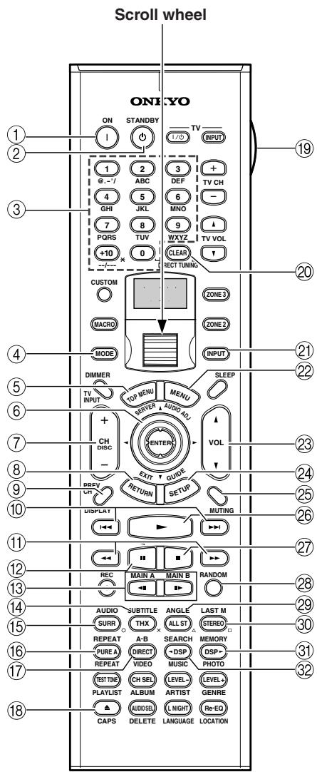
RC-557M
RC-558M
① ON button
This button is used to turn on the DVD player.
② STANDBY button
This button is used to set the DVD player to Standby.
③ Number/letter buttons
These buttons are used to enter title, chapter, and track numbers and to enter times for locating specific points in time.
④ MODE button
This button is used with the scroll wheel to select the remote controller modes. Press this button first, and then roll the scroll wheel until "DVD" appears on the display.
⑤ TOP MENU button
This button is used to select a DVD's top menu.
⑥ Up/Down/Left/Right [▲]/[▼]/[▲] /[▶] & ENTER buttons
These buttons are used to navigate DVD menus and the DVD player's onscreen setup menus. The [ENTER] button is used to start playback of the selected menu title, chapter, or track and to confirm settings.
⑦ CH/DISC +/- button
This button is used to select discs on a DVD changer.
(8) RETURN/EXIT button
This button is used to exit the DVD player's onscreen setup menu and to restart menu playback.
⑨ DISPLAY button
This button is used to display information about the current disc, title, chapter, or track, including the elapsed time, remaining time, total time, and so on.
10 Previous/Next [▶] buttons
The Previous [▶] button is used to select the previous chapter or track. During playback it selects the beginning of the current chapter or track. The Next [▶] button is used to select the next chapter or track.
⑪ FR/FF [←]/[▶] buttons
The FR [ ] button is used to start fast reverse. The FF [ ] button is used to start fast forward.
Pause [ ] button
This button is used to pause DVD playback.
Step/Slow [<][][] buttons
These buttons are used for frame-by-frame playback and slow-motion playback.
14 SUBTITLE button
This button is used to select subtitles.
15 AUDIO button
This button is used to select foreign language soundtracks and audio formats (e.g., Dolby Digital or DTS).
16 REPEAT button
This button is used to set the repeat playback functions.
(17) A-B button
This button is used to set the A-B repeat playback function.
18 Open/Close [△] button
This button is used to open and close the disc tray.
19 LIGHT button
This button is used to turn on or off the remote controller's illuminated buttons.
20 CLEAR button
This button is used to cancel functions and to clear entered numbers.
21 INPUT button
This button is used to select the input source. Press this button first, and then roll the scroll wheel until "DVD" appears on the display.
22 MENU button
This button is used to select a DVD's menu.
23 VOL 1/1 button
This button is used to set the volume of the TX-NR1000/TX-NR5000E.
24 SETUP/GUIDEButton
This button is used to access the DVD player's onscreen setup menus.
25 MUTING button
This button is used to mute the TX-NR1000/ TX-NR5000E. This function can be set only with the remote controller.
26 Play [▶] button
This button is used to start DVD playback.
② Stop [■] button
This button is used to stop DVD playback.
28 RANDOM button
This button is used with the random playback function.
29 ANGLE button
This button is used to select different camera angles.
30 LAST M button
This button is used with the last memory function, which allows you to resume DVD playback from where you left off.
③ MEMORY button
This button is used with the memory playback function, which allows you to create a custom playlist of titles, chapters, or tracks.
32 SEARCH button
This button is used to search for titles, chapters, tracks, and specific points in time.
CD Mode
CD mode is used to control an Onkyo CD player connected to the TX-NR1000/TX-NR5000E via R1. To select CD mode, press the [MODE] button, and then roll the scroll wheel until "CD" appears on the display.
Note:
While neither the [INPUT] button nor [MODE] button is illuminated, rolling the scroll wheel changes the input source and remote controller mode simultaneously (when you enter the CD mode, be sure that the LCD display shows "CD" in both of the top and bottom lines).
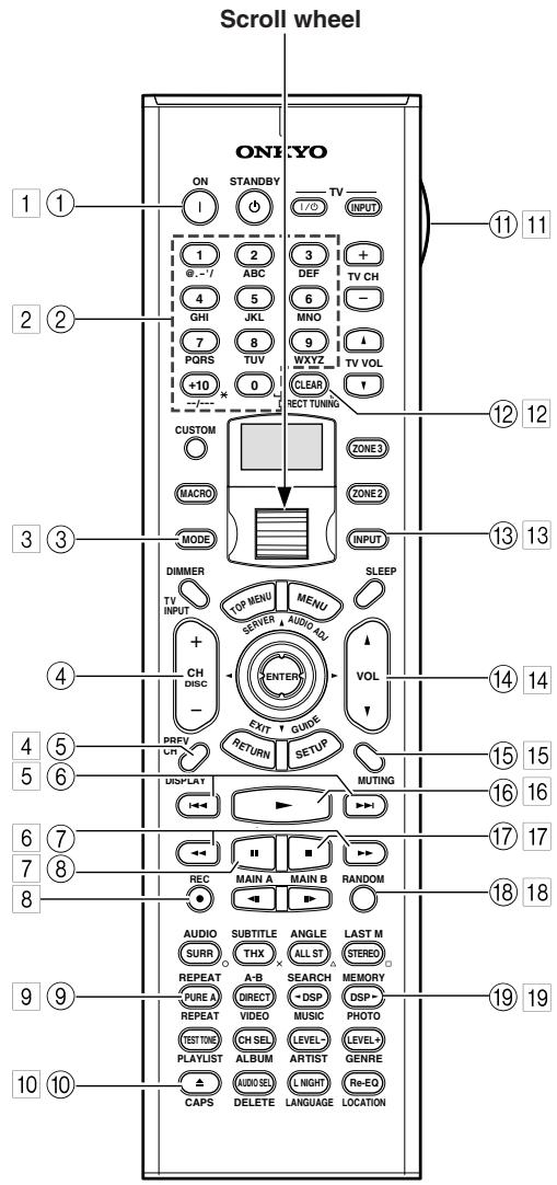
BC-557M
RC-558M
Boxed numbers are for MiniDisc mode (See page 127).
① ON button
This button is used to set the CD player to On or Standby.
② Number/letter buttons
These buttons are used to enter track numbers.
③ MODE button
This button is used with the scroll wheel to select the remote controller modes. Press this button first, and then roll the scroll wheel until "CD" appears on the display.
CH/DISC +/- button
This button is used to select discs on a CD changer.
⑤ DISPLAY button
This button is used to display information about the current disc or track, including the elapsed time, remaining time, total time, and so on.
(6) Previous/Next [▶] buttons
The Previous [▶] button is used to select the previous track. During playback it selects the beginning of the current track. The Next [▶] button is used to select the next track.
The FR [] button is used to start fast reverse.
The FF [ ] button is used to start fast forward.
⑧ Pause [ ] button
This button is used to pause CD playback.
⑨ REPEAT button
This button is used to set the repeat playback functions.
10 Open/Close [▲] button
This button is used to open and close the disc tray.
11 LIGHT button
This button is used to turn on or off the remote controller's illuminated buttons.
12 CLEAR button
This button is used to cancel functions and to clear entered numbers.
13 INPUT button
This button is used to select the input source. Press this button first, and then roll the scroll wheel until "CD" appears on the display.
14 VOL 1/1 button
This button is used to set the volume of the TX-NR1000/TX-NR5000E.
15 MUTING button
This button is used to mute the TX-NR1000/ TX-NR5000E. This function can be set only with the remote controller.
16 Play [▶] button
This button is used to start CD playback.
⑰ Stop [■] button
This button is used to stop CD playback.
18 RANDOM button
This button is used with the random playback function.
⑲ MEMORY button
This button is used with the memory playback function, which allows you to create a custom playlist of tracks.
MiniDisc Mode
MiniDisc mode is used to control an Onkyo MiniDisc recorder connected to the TX-NR1000/TX-NR5000E via R1. To select MiniDisc mode, press the [MODE] button, and then roll the scroll wheel until "MD" appears on the display.
Note:
While neither the [INPUT] button nor [MODE] button is illuminated, rolling the scroll wheel changes the input source and remote controller mode simultaneously (When you select "TAPE2" as the top line, "MD" appears in the bottom line.)
1 ON button
This button is used to set the MiniDisc recorder to On or Standby.
2 Number/letter buttons
These buttons are used to enter track numbers and to enter times for locating specific points in time.
3 MODE button
This button is used with the scroll wheel to select the remote controller modes. Press this button first, and then roll the scroll wheel until "MD" appears on the display.
4 DISPLAY button
This button is used to display information about the current disc or track, including the elapsed time, remaining time, total time, and so on.
Previous/Next [▶] buttons
The Previous [ ] button is used to select the previous track. During playback it selects the beginning of the current track. The Next [ ] button is used to select the next track.
6 FR/FF [←]按钮
The FR [] button is used to start fast reverse.
The FF [ ] button is used to start fast forward.
7 Pause [ ] button
This button is used to pause MiniDisc playback.
REC [●] button
This button is used to start MiniDisc recording.
9 REPEAT button
This button is used to set the repeat playback functions.
10Eject[△]button
This button is used to set eject the MiniDisc.
11 LIGHT button
This button is used to turn on or off the remote controller's illuminated buttons.
12 CLEAR button
This button is used to cancel functions and to clear entered numbers.
13 INPUT button
This button is used to select the input source. Press this button first, and then roll the scroll wheel until "TAPE2" appears on the display.
14 VOL 1/7 button
This button is used to set the volume of the TX-NR1000/TX-NR5000E.
15 MUTING button
This button is used to mute the TX-NR1000/ TX-NR5000E. This function can be set only with the remote controller.
16 Play [▶] button
This button is used to start MiniDisc playback.
17 Stop [■] button
This button is used to stop MiniDisc playback.
18 RANDOM button
This button is used with the random playback function.
19 MEMORY button
This button is used with the memory playback function, which allows you to create a custom playlist of tracks.
Tape Mode
Tape mode is used to control an Onkyo cassette recorder connected to the TX-NR1000/TX-NR5000E via R1. To select Tape mode, press the scroll wheel, placing your remote controller into "AMP" mode.
Note:
While neither the [INPUT] button nor [MODE] button is illuminated, rolling the scroll wheel changes the input source and remote controller mode simultaneously (When you select "TAPE1" as the top line, "AMP" appears in the bottom line.).
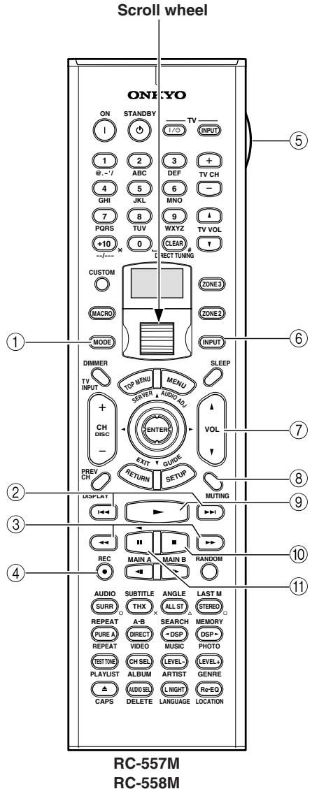
① MODE button
This button is used with the scroll wheel to select the remote controller modes. Press the scroll wheel until "AMP" appears on the display.
② Previous/Next [▶] buttons
The Previous [▶] button is used to select the previous track. During playback it selects the beginning of the current track. The Next [▶] button is used to select the next track.
The Previous/Next [1 1] / [1 1] buttons may not work properly with some cassette tapes depending on how they were recorded.
③ Rewind/FF [←]/[▶] buttons
The Rewind [] button is used to start rewind.
The FF [ ] button is used to start fast forward.
④ REC [●] button
This button is used to start tape recording.
⑤ LIGHT button
This button is used to turn on or off the remote controller's illuminated buttons.
⑥ INPUT button
This button is used to select the input source. Press this button first, and then roll the scroll wheel until "TAPE1" appears on the display.
⑦ VOL 1/1 button
This button is used to set the volume of the TX-NR1000/TX-NR5000E.
(8) MUTING button
This button is used to mute the TX-NR1000/ TX-NR5000E. This function can be set only with the remote controller.
⑧ Play [▶] button
This button is used to start tape playback.
10 Stop [■] button
This button is used to stop tape playback.
⑪ Reverse Play [ ] button
This button is used to start reverse playback.
Using the Remote Controller with Other Components
You can use the TX-NR1000/TX-NR5000E's remote controller (RC-557M/558M) to control your other AV components, including those made by other manufacturers. To do this you can:
- Enter a remote control code for the component that you want to control (e.g., DVD, TV, VCR).
- Learn commands directly from the other component's remote controller (see page 136).
- Use the Macro function to learn a sequence of actions (see page 137).
Entering a Remote Control Code
By entering the appropriate remote control code for each of your components, you can control each component by selecting the relevant remote controller mode: DVD, TV, VCR, CBL (cable), or SAT (satellite).
| 1 | Look up the appropriate remote control code for the component. See “Remote Control Codes” on pages 130-133. |
| 2 CUSTOM | Press and hold down the [CUS-TOM] button for more than three seconds. The remote controller enters Custom mode. |
| 3 | Roll the scroll wheel to select “PRGRM,” and then press the scroll wheel. |
| 4 | Roll the scroll wheel to select the the remote controller mode you want to use with the component, and then press the scroll wheel. The following remote controller modes can be selected: DVD, TV, VCR, CBL, or SAT. |
| 5 1 2 3 6 -1 ABC DEF 4 GHJ KKL MNO 7 PQRS TUV WXYZ | Use the number buttons to enter the 4-digit remote control code. If the code is accepted, the following appears on the display for a while, and then the normal display reappears. If the code is not accepted, after the message “RETRY” has been displayed, the code entry display reappears, and you should try entering the code again. To cancel this procedure at any point, press the [CUSTOM] button. |
| 6 | Select the remote controller mode, point the remote controller at the component, and check its operation. The remote controller buttons that can be used in DVD mode are shown on page 124. Those that can be used with the TV, VCR, CBL, and SAT modes are listed on pages 134 and 135. |
Remote Control Codes for an Onkyo DVD player
The remote control code that you use with an Onkyo DVD player depends on whether it's connected via RI, as follows:
5001: Use this code if you've connected an RI cable and an RCA/phono analog audio connection cable to your DVD player. This is the default setting, so if you're using RI, you don't need to change it. Point the remote controller at the TX-NR1000/ TX-NR5000E to operate the DVD player.
5002: Use this code if your DVD player doesn't have an RI socket, or you're not using RI. Point the remote controller at the DVD player to operate it.
Remote Control Codes
When two or more codes are given, try each one in turn, and choose the one that works best.
DVD (DVD player)
| Manufacturer | Control code |
| Aiwa | 5010 |
| Akai | 5019 |
| Apex | 5015, 5016 |
| CyberHome | 5027 |
| Denon | 5017, 5020 |
| GE | 5003 |
| Hitachi | 5009 |
| Integra | 5001, 5002 |
| Integra Research | 5001, 5002 |
| JVC | 5023 |
| Kenwood | 5017 |
| Magnavox | 5004, 5021 |
| Marantz | 5025, 5026 |
| Mitsubishi | 5005 |
| Onkyo | 5001, 5002 |
| Panasonic | 5011, 5017, 5020 |
| Philips | 5004, 5021, 5028 |
| Pioneer | 5006 |
| Proscan | 5003 |
| RCA | 5003 |
| Sanyo | 5012 |
| Sony | 5007, 5013, 5018, 5029 |
| Technics | 5020 |
| Thomson | 5022, 5024 |
| Toshiba | 5008, 5021 |
| Xbox | 5022 |
| Yamaha | 5020 |
| Zenith | 5014, 5021 |
SAT (satellite tuner)
| Manufacturer | Control code |
| Alba | 4014, 4017, 4025, 4027 |
| Allsat | 4015, 4027 |
| Altech | 4022, 4025 |
| Amstrad | 4013, 4019, 4025, 4030, 4031 |
| Anglo | 4025 |
| Ankaro | 4025 |
| Anttron | 4017 |
| Apollo | 4017 |
| Arcon | 4016 |
| Armstrong | 4013 |
| Asat | 4016 |
| Astra | 4013, 4016, 4024 |
| Astro | 4019, 4020 |
| AudioTon | 4015 |
| Bush | 4012, 4014 |
| Condor | 4024 |
| Conrad | 4024 |
| Cosat | 4015, 4023 |
| Crown | 4013 |
SAT (satellite tuner)
| Manufacturer | Control code |
| Daewoo | 4016, 4017, 4025 |
| Diamond | 4022 |
| Dishnet | 4008 |
| Dual | 4016 |
| Echostar | 4010, 4018, 4025 |
| Einhell | 4013, 4017, 4025 |
| Elta | 4015, 4017 |
| Engel | 4025 |
| Eurosat | 4013, 4022 |
| Eurosky | 4013, 4024 |
| Eurostar | 4024 |
| Fagor | 4015, 4023 |
| Ferguson | 4012 |
| Fidelity | 4030 |
| Fracarro | 4017 |
| FTE | 4025, 4030 |
| Fuba | 4017 |
| Galaxis | 4015, 4023 |
| GE | 4001, 4002 |
| General Instruments | 4003 |
| GMI | 4013 |
| Grundig | 4021, 4029, 4031 |
| Hinari | 4017 |
| Hirschmann | 4019, 4035 |
| Hitachi | 4036, 4037 |
| Hughes Network Systems | 4011 |
| Huth | 4013, 4015, 4024 |
| Imperial | 4014 |
| Intertronic | 4013 |
| Intervision | 4015, 4023, 4024 |
| Johansson | 4015 |
| JVC | 4009, 4021 |
| Kathrein | 4025 |
| Kolon | 4017 |
| K-SAT | 4025 |
| Kyostar | 4017 |
| Lasat | 4013, 4020, 4024 |
| Lenco | 4016, 4017, 4025 |
| Lennox | 4023 |
| Loewe | 4013 |
| Lorenzen | 4024 |
| Macab | 4022 |
| Manhattan | 4015, 4020, 4023 |
| Maspro | 4021, 4025 |
| Matsui | 4021 |
| Mediamarkt | 4013 |
| Medion | 4025 |
| Metronic | 4013, 4017, 4020 |
| Micro Technology | 4025 |
| Minerva | 4021 |
| Morgan's | 4013, 4015, 4025 |
| Mysat | 4025 |
| Neuhaus | 4019, 4023, 4024, 4025 |
| Neusat | 4025 |
| Nikko | 4013, 4025, 4027 |
| Nokia | 4033 |
| Nordmende | 4017, 4020 |
SAT (satellite tuner)
| Manufacturer | Control code |
| Oceanic | 4022 |
| Octagon | 4016, 4017 |
| Okano | 4013 |
| Optex | 4015, 4023 |
| Orbit | 4016 |
| Orbitech | 4017, 4019 |
| Pace | 4012, 4026, 4031 |
| Pacific | 4022 |
| Palladium | 4013, 4017, 4021 |
| Palsat | 4019 |
| Panasonic | 4006, 4031 |
| Panda | 4024 |
| Philips | 4021, 4029 |
| Phonotrend | 4015, 4023 |
| Predki | 4017 |
| Premier | 4023 |
| Primestar | 4007 |
| Proscan | 4001, 4002 |
| Protek | 4022 |
| Pye | 4021 |
| Quelle | 4024 |
| Radix | 4035 |
| RCA | 4001, 4002 |
| Roadster | 4025 |
| Rover | 4025 |
| Saba | 4014, 4020, 4024, 4027 |
| Samsung | 4017 |
| Satcom | 4024 |
| SatPartner | 4017, 4020, 4027, 4030 |
| Schneider | 4029 |
| Sedea Electronique | 4017 |
| Seemann | 4013 |
| SEG | 4017, 4028 |
| Seleco | 4015, 4023 |
| Skymaster | 4025, 4034 |
| Skyvision | 4015 |
| Sony | 4005, 4031 |
| Strong | 4016, 4017, 4020 |
| Sunstar | 4013 |
| Techniland | 4015, 4023 |
| TechniSat | 4019 |
| Teco | 4013, 4016 |
| Teleciel | 4027 |
| Telefunken | 4017 |
| Teleka | 4013 |
| Telemaster | 4020 |
| Telewire | 4015, 4023 |
| Tensai | 4016 |
| Thomson | 4024, 4025 |
| Thorens | 4022 |
| Tonna | 4015, 4023, 4025 |
| Toshiba | 4004 |
| Triasat | 4019 |
| Tristar | 4016 |
| Unisat | 4013 |
SAT (satellite tuner)
| Manufacturer | Control code |
| Universum | 4021, 4024 |
| Vortec | 4017 |
| Wela | 4025 |
| Zehnder | 4020 |
| Zenith | 4032 |
CBL (cable receiver)
| Manufacturer | Control code |
| ABC | 3001, 3002, 3021 |
| Archer | 3006 |
| Cabletime | 3028, 3032 |
| Cableview | 3004 |
| Contec | 3009 |
| Eastern | 3010 |
| GE | 3001, 3002 |
| Gemini | 3011 |
| General Instruments | 3002, 3022 |
| Grundig | 3031 |
| Hamlin | 3012 |
| Hitachi | 3002 |
| Jerrold | 3002, 3011, 3013, 3021, 3022, 3023, 3026 |
| Magnavox | 3014 |
| Memorex | 3015 |
| Movie Time | 3016 |
| NEC | 3003 |
| Nokia | 3033 |
| NSC | 3016 |
| Oak | 3009 |
| Panasonic | 3020 |
| Philips | 3007, 3008, 3014 |
| Pioneer | 3017, 3024 |
| Proscan | 3001, 3002 |
| RCA | 3004, 3020, 3022 |
| Realistic | 3006 |
| Sagem | 3034 |
| Salora | 3029 |
| Samsung | 3017 |
| Signature | 3002 |
| Sprucer | 3020 |
| Standard Component | 3018 |
| Starcom | 3011, 3021 |
| Stargate | 3011 |
| Tele+1 | 3030 |
| Tocom | 3013 |
| United Cable | 3021, 3023 |
| Universal | 3005, 3006 |
| Videoway | 3025 |
| View Star | 3009, 3014, 3016 |
| Zenith | 3019 |
VCR
| Manufacturer | Control code |
| Aiwa | 2012, 2046, 2047 |
| Akai | 2003, 2004, 2022 |
| Alba | 2033, 2041, 2044, 2045, 2047 |
| Anitech | 2033 |
| ASA | 2034 |
| Baird | 2036 |
| Bell & Howell | 2007 |
| Blaupunkt | 2039, 2042 |
| Bush | 2033, 2041, 2044, 2045, 2047 |
| Canon | 2010, 2011 |
| Carver | 2014 |
| Cimline | 2033 |
| Citizen | 2008, 2009 |
| Colortyme | 2005 |
| Craig | 2008 |
| Crown | 2033 |
| Curtis Mathes | 2001, 2005, 2008, 2009, 2010, 2011, 2023, 2026 |
| Cyrus | 2034 |
| Daewoo | 2012 |
| Dansai | 2033 |
| Decca | 2034 |
| Dimensia | 2001, 2026 |
| Dumont | 2034, 2036, 2037 |
| Elcatech | 2033 |
| Emerson | 2003, 2010, 2012, 2022 |
| ESC | 2043 |
| Ferguson | 2035 |
| Finlandia | 2034, 2036 |
| Finlux | 2034, 2036, 2037 |
| Firstline | 2033, 2041 |
| Fisher | 2007, 2030, 2036 |
| Fuji | 2004, 2010, 2024 |
| Funai | 2012 |
| Garrard | 2012 |
| GE | 2001, 2002, 2008, 2010, 2011, 2023, 2025, 2026 |
| GEC | 2034 |
| GoldHand | 2033 |
| GoldStar | 2005, 2009 |
| Goodmans | 2031, 2033 |
| Gradient | 2012 |
| Graetz | 2036, 2043 |
| Granada | 2030, 2034, 2036 |
| Grandin | 2033 |
| Grundig | 2029, 2033, 2034, 2039, 2040, 2042, 2044 |
| Harman Kardon | 2005 |
| HCM | 2033, 2044 |
| Hinari | 2028, 2033, 2043, 2044, 2047 |
| Hitachi | 2013, 2021, 2025, 2028, 2037, 2038, 2043 |
| Ingersol | 2028 |
| Interfunk | 2034 |
| ITT | 2030, 2036, 2043, 2048 |
| JC Penney | 2005, 2006, 2007, 2008, 2010, 2011, 2013, 2014, 2021 |
VCR
| Manufacturer | Control code |
| Jensen | 2013 |
| JVC | 2005, 2006, 2007, 2009, 2032, 2035, 2040, 2048 |
| Kaisui | 2033 |
| Kendo | 2041, 2046 |
| Kenwood | 2005, 2006, 2007, 2009 |
| Kodak | 2010 |
| Loewe | 2028, 2034 |
| Logik | 2028, 2043 |
| Luxor | 2030, 2031, 2036 |
| Magnavox | 2010, 2011, 2014, 2019, 2020 |
| Marantz | 2005, 2006, 2007, 2009, 2010, 2014, 2031, 2034 |
| Matsui | 2028, 2041, 2046, 2047 |
| Matsushita | 2010 |
| Memorex | 2007, 2008, 2010, 2012, 2019, 2030, 2036 |
| Metz | 2039 |
| MGA | 2022 |
| Minerva | 2039 |
| Minolta | 2013, 2021 |
| Mitsubishi | 2013, 2022, 2032, 2034 |
| Motorola | 2010 |
| MTC | 2008 |
| Multitech | 2008, 2012, 2033 |
| NEC | 2005, 2006, 2007, 2009, 2032 |
| Neckermann | 2034 |
| Nesco | 2033 |
| NOBLEX | 2008 |
| Nokia | 2030, 2036, 2043 |
| Nordmende | 2048 |
| Okano | 2046 |
| Olympus | 2010 |
| Optonica | 2017 |
| Orion | 2028, 2041, 2045, 2046, 2047 |
| Osaki | 2033 |
| Otto Versand | 2034 |
| Palladium | 2033 |
| Panasonic | 2010, 2011, 2042 |
| Pentax | 2013, 2021, 2025, 2037 |
| Pentex Research | 2009 |
| Philco | 2010, 2011, 2014 |
| Philips | 2010, 2014, 2017, 2034, 2048 |
| Phonola | 2034 |
| Pioneer | 2006, 2013, 2032, 2034 |
| Proline | 2044 |
| Proscan | 2001, 2002, 2026 |
| Pye | 2034 |
| Quasar | 2010, 2011 |
| Quelle | 2034 |
| Radio Shack | 2017 |
| Radio Shack/Realistic | 2007, 2008, 2010, 2011, 2012, 2017 |
| Radiola | 2034 |
| VCR | |
| Manufacturer | Control code |
| RCA | 2001, 2002, 2003, 2008, 2010, 2013, 2021, 2023, 2025, 2026, 2027 |
| Realistic | 2007, 2008, 2010, 2011, 2012, 2017 |
| Rex | 2048 |
| Roadstar | 2033, 2043 |
| Runco | 2019 |
| Saba | 2040, 2048 |
| Saisho | 2028, 2041 |
| Salora | 2030 |
| Samsung | 2008, 2043, 2049 |
| Sansui | 2006, 2032 |
| Sanyo | 2007, 2008, 2030, 2036 |
| Saville | 2047 |
| SBR | 2034 |
| Schaub Lorenz | 2036 |
| Schneider | 2033, 2034 |
| Scott | 2015 |
| Sears | 2007, 2010, 2013, 2021 |
| SEG | 2043 |
| SEI | 2028, 2034 |
| Sharp | 2016, 2017, 2031 |
| Shintom | 2004, 2033, 2036 |
| Shorai | 2028 |
| Siemens | 2034, 2036, 2039 |
| Singer | 2010 |
| Sinudyne | 2028, 2034 |
| Sonolor | 2030, 2031 |
| Sony | 2004, 2018, 2024 |
| STS | 2010, 2021 |
| Sunkai | 2046 |
| Sylvania | 2010, 2011, 2012, 2014 |
| Symphonic | 2012 |
| Tandy | 2007 |
| Tatung | 2034 |
| Teac | 2012 |
| Technics | 2010, 2042 |
| Teknika | 2010, 2012 |
| Telefunken | 2048 |
| Thomson | 2048 |
| Thorn | 2035, 2036 |
| Toshiba | 2013, 2015, 2022, 2034, 2048 |
| Totevision | 2008 |
| Uher | 2043 |
| Unitech | 2008 |
| Universum | 2034, 2039, 2043 |
| Vector Research | 2005, 2006 |
| Video Concepts | 2005, 2006, 2022 |
| Wards | 2008, 2010, 2012, 2013, 2017, 2021, 2027 |
| XR-1000 | 2010, 2012 |
| Yamaha | 2005, 2006, 2007, 2009 |
| Yoko | 2043 |
| Zenith | 2004, 2019, 2024 |
| TV | |
| Manufacturer | Control code |
| Admiral | 1026, 1040, 1062 |
| Akai | 1002, 1067 |
| Akura | 1045 |
| Alba | 1035, 1043 |
| Amplivision | 1063 |
| Amstrad | 1035, 1067 |
| Amtron | 1009 |
| Anam National | 1003, 1009 |
| Anitech | 1035 |
| AOC | 1004, 1005, 1006 |
| Arc en Ciel | 1066 |
| Arcam | 1063 |
| ASA | 1040 |
| Audiovox | 1009 |
| Autovox | 1040, 1068 |
| Baird | 1069 |
| Bang & Olufsen | 1040 |
| Baur | 1036, 1054, 1055, 1058, 1059, 1068 |
| Beko | 1052 |
| Bell & Howell | 1010, 1017 |
| Binatone | 1063 |
| Blaupunkt | 1041, 1042, 1044, 1058, 1059 |
| Boots | 1063 |
| Brionvega | 1040 |
| Bruns | 1040 |
| BSR | 1048 |
| Bush | 1035, 1043, 1048, 1050, 1053, 1057 |
| Cascade | 1035 |
| Celebrity | 1002 |
| Century | 1040 |
| Cimline | 1035, 1043 |
| Citizen | 1004, 1006, 1009, 1017, 1022, 1025 |
| Clatronic | 1052 |
| Colortyme | 1004, 1006 |
| Condor | 1052 |
| Contec | 1035 |
| Contec/Cony | 1007, 1009 |
| Continental Edison | 1066 |
| Craig | 1009 |
| Crosley | 1040 |
| Crown | 1009, 1014, 1035, 1052 |
| Curtis Mathes | 1001, 1004, 1006, 1010, 1017, 1022, 1025, 1034 |
| Daewoo | 1004, 1005, 1006, 1025, 1035, 1053 |
| Daytron | 1004, 1006, 1025, 1035 |
| Decca | 1067 |
| Dimensia | 1001, 1034 |
| Dixi | 1035 |
| Dual | 1057, 1068 |
| Dumont | 1004, 1039, 1040 |
| Electroband | 1002 |
| Electrohome | 1002, 1003, 1004, 1006, 1008 |
| Elta | 1035 |
| TV | |
| Manufacturer | Control code |
| Emerson | 1004, 1006, 1007, 1009, 1010, 1017, 1025, 1027, 1029, 1033, 1040, 1070 |
| Envision | 1004, 1006 |
| Erres | 1037 |
| Europhon | 1067 |
| Fidelity | 1068 |
| Finlux | 1039, 1040, 1067 |
| Firstline | 1035, 1043, 1048, 1049, 1063 |
| Fisher | 1010, 1017, 1052, 1063, 1068 |
| Formenti | 1040 |
| Frontech | 1045, 1062 |
| Fujitsu | 1070 |
| Funai | 1009, 1045, 1048, 1070 |
| GE | 1001, 1003, 1004, 1006, 1011, 1012, 1019, 1034 |
| GEC | 1038, 1063, 1067, 1069 |
| Geloso | 1035 |
| Genexxa | 1062 |
| GoldStar | 1004, 1005, 1006, 1007, 1008, 1025, 1047, 1063 |
| Goodmans | 1043, 1053, 1063 |
| Gorenje | 1052 |
| Graetz | 1062, 1069 |
| Granada | 1063, 1067 |
| Grundig | 1039, 1041, 1042, 1058, 1059, 1064 |
| Hallmark | 1004, 1006 |
| Hanseatic | 1060, 1068 |
| Hantarex | 1067 |
| HCM | 1035 |
| Hinari | 1035, 1043 |
| Hitachi | 1004, 1006, 1007, 1013, 1027, 1038, 1062, 1063, 1069 |
| Huanyu | 1053 |
| ICE | 1045, 1063 |
| Imperial | 1052 |
| Infinity | 1014 |
| Inno Hit | 1056, 1067 |
| Interfunk | 1055, 1062, 1066, 1069 |
| Intervision | 1045, 1063 |
| ITT | 1062, 1068, 1069 |
| JBL | 1014 |
| JC Penney | 1001, 1004, 1005, 1006, 1011, 1012, 1016, 1019, 1022, 1025, 1034 |
| Jensen | 1004, 1006 |
| JVC | 1007, 1012, 1013, 1015, 1033 |
| Kaisui | 1035, 1063 |
| Kapsch | 1062, 1069 |
| Kathrein | 1060 |
| Kawasho | 1002, 1004, 1006 |
| Kendo | 1043 |
| Kenwood | 1004, 1006, 1008 |
| Kloss Novabeam | 1009 |
| Korting | 1040 |
| KTV | 1009, 1025 |
| LG | 1005 |
TV
| Manufacturer | Control code |
| Loewe | 1014, 1040, 1055 |
| Luxman | 1004, 1006 |
| LXI | 1001, 1006, 1010, 1014, 1016, 1017, 1034 |
| M Electronic | 1035, 1053, 1062, 1063 |
| Magnadyne | 1040, 1067, 1068 |
| Magnafon | 1067 |
| Magnavox | 1004, 1006, 1008, 1014, 1018, 1020 |
| Marantz | 1004, 1006, 1014, 1060 |
| Matsui | 1035, 1043, 1048, 1050, 1063, 1064, 1067, 1068 |
| Megatron | 1006 |
| Memorex | 1005, 1006, 1010, 1017, 1035 |
| Metz | 1040, 1051, 1058 |
| MGA | 1004, 1005, 1006, 1008 |
| Minerva | 1039, 1058, 1059, 1064 |
| Mitsubishi | 1004, 1005, 1006, 1008, 1040, 1055, 1058 |
| Mivar | 1047, 1056, 1067 |
| Motorola | 1003, 1026 |
| MTC | 1004, 1005, 1006, 1022, 1055 |
| Multitech | 1009, 1035 |
| NAD | 1006, 1016 |
| NEC | 1003, 1004, 1005, 1006 |
| Neckermann | 1040, 1041, 1054, 1059, 1060 |
| Nikkai | 1045 |
| Nikko | 1006 |
| Oceanic | 1062 |
| Onwa | 1009 |
| Optonica | 1021, 1026 |
| Orion | 1029, 1043, 1048, 1049, 1050, 1067, 1068 |
| Osaki | 1045, 1063 |
| Otto Versand | 1036, 1041, 1043, 1054, 1055, 1058, 1059, 1060, 1063 |
| Palladium | 1052 |
| Panasonic | 1003, 1012, 1014, 1031, 1044, 1046, 1051, 1061, 1062, 1069 |
| Pathe Marconi | 1066 |
| Philco | 1003, 1004, 1005, 1006, 1007, 1008, 1014, 1018, 1040 |
| Philips | 1003, 1004, 1007, 1008, 1014, 1018, 1019, 1020, 1037, 1038, 1040, 1053, 1059, 1060 |
| Phoenix | 1040 |
| Phonola | 1037, 1040 |
TV
| Manufacturer | Control code |
| Pioneer | 1004, 1006, 1027, 1062 |
| Portland | 1004, 1005, 1006, 1025 |
| Price Club | 1022 |
| Prism | 1012 |
| Profex | 1035 |
| Proline | 1049 |
| Proscan | 1001, 1034 |
| Protech | 1035, 1045, 1063 |
| Proton | 1004, 1006, 1007 |
| Pye | 1037 |
| Quasar | 1003, 1012, 1031 |
| Quelle | 1036, 1039, 1054, 1055, 1058, 1059, 1068 |
| Radio Shack | 1010, 1017, 1034 |
| Radio Shack/Realistic | 1001, 1004, 1006, 1007, 1009, 1010, 1017, 1021, 1025 |
| Radiola | 1037 |
| Radiomarelli | 1040, 1067 |
| RCA | 1001, 1003, 1004, 1005, 1006, 1008, 1027, 1034 |
| Realistic | 1010, 1017, 1034 |
| Rex | 1045, 1062 |
| RFT | 1040 |
| Roadstar | 1035, 1045 |
| Saba | 1040, 1062, 1066, 1069 |
| Saisho | 1035, 1043, 1045, 1067, 1068 |
| Salora | 1062 |
| Sambers | 1056, 1067 |
| Sampo | 1004, 1006, 1025 |
| Samsung | 1004, 1005, 1006, 1007, 1008, 1022, 1025, 1035, 1045, 1047, 1052, 1056, 1060, 1063, 1065 |
| Sansui | 1029 |
| Sanyo | 1004, 1010, 1017 |
| SBR | 1037, 1038 |
| Schaub Lorenz | 1069 |
| Schneider | 1068 |
| Scott | 1004, 1006, 1007, 1009, 1070 |
| Sears | 1001, 1004, 1006, 1008, 1010, 1015, 1016, 1017, 1028, 1034, 1070 |
| SEG | 1045, 1063 |
| SEI | 1036, 1040, 1048, 1067, 1068 |
| Seleco | 1062 |
| Sharp | 1004, 1006, 1007, 1021, 1023, 1025, 1026 |
| Shorai | 1048 |
| Siarem | 1040, 1067 |
TV
| Manufacturer | Control code |
| Siemens | 1041, 1042, 1058, 1059 |
| Singer | 1040 |
| Sinudyne | 1036, 1040, 1043, 1067, 1068 |
| Solavox | 1062 |
| Sonoko | 1035 |
| Sonolor | 1062 |
| Sony | 1002, 1030, 1032, 1036, 1054 |
| Sounddesign | 1004, 1006, 1009, 1070 |
| Starlite | 1009 |
| Stern | 1062 |
| Sunkai | 1043, 1048, 1049, 1050 |
| Sylvania | 1004, 1006, 1008, 1014, 1018, 1020 |
| Symphonic | 1009, 1028 |
| Tandy | 1026, 1062, 1063 |
| Tashiko | 1038, 1063 |
| Tatung | 1003, 1063, 1067 |
| Tec | 1063 |
| Technics | 1012, 1044, 1061 |
| Techwood | 1004, 1006, 1012 |
| Teknika | 1004, 1005, 1006, 1007, 1009, 1022, 1025, 1031, 1070 |
| Teleavia | 1066 |
| Telecaption | 1024 |
| Telefunken | 1066 |
| Teletech | 1035 |
| Teleton | 1063 |
| Tensai | 1048 |
| Thomson | 1066 |
| Thorn | 1054, 1055, 1058 |
| Toshiba | 1010, 1016, 1017, 1022, 1024, 1039 |
| Totevision | 1025 |
| Triumph | 1067 |
| Universal | 1011, 1019 |
| Universum | 1045, 1052, 1058 |
| Voxson | 1040, 1062 |
| Waltham | 1063 |
| Wards | 1001, 1004, 1005, 1006, 1008, 1011, 1014, 1018, 1019, 1020, 1021, 1034, 1070 |
| Watt Radio | 1068 |
| Wega | 1040 |
| Yamaha | 1004, 1005, 1006, 1008 |
| Yoko | 1045, 1063 |
| Zenith | 1004 |
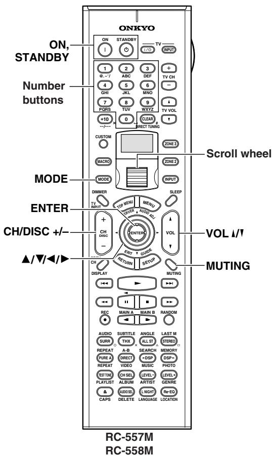
Controlling a Satellite Tuner
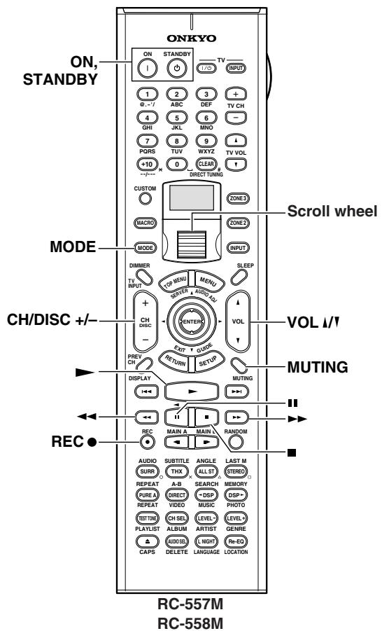
Controlling a VCR
- Roll the scroll wheel to select the input source and the remote controller mode for your satellite tuner.
Perform this operation while both the [MODE] and [INPUT] buttons are not illuminated. If you want to operate only the satellite tuner without changing the input source, press the [MODE] button and roll the scroll wheel to select "SAT." - Point the remote controller at your satellite tuner, and use the following buttons (you must enter appropriate remote control code first).
| ON, STANDBY | Set the satellite tuner to On or Standby |
| CH/DISC +/- | Select satellite channels |
| ▲/▼/<▲ | Select menu items |
| ENTER | Confirm selection |
| Number buttons | Enter numbers |
The following buttons control the TX-NR1000/ TX-NR5000E.
| VOL ↓/↑ | Adjust the TX-NR1000/TX-NR5000E volume |
| MUTING | Mute the TX-NR1000/TX-NR5000E |
- Roll the scroll wheel to select the input source and the remote controller mode for your VCR. Perform this operation while both the [MODE] and [INPUT] buttons are not illuminated. If you want to operate only the VCR without changing the input source, press the [MODE] button and roll the scroll wheel to select "VCR."
- Point the remote controller at your VCR, and use the following buttons (you must enter appropriate remote control code first).
| ON, STANDBY | Set the VCR to On or Standby |
| CH/DISC +/- | Select TV channels |
| ► | Play |
| ■ | Stop |
| ← | Rewind |
| ► | Fast forward |
| ■ | Pause |
| REC ● | Record |
The following buttons control the TX-NR1000/TX-NR5000E.
| VOL 1/1 | Adjust the TX-NR1000/TX-NR5000E volume |
| MUTING | Mute the TX-NR1000/TX-NR5000E |
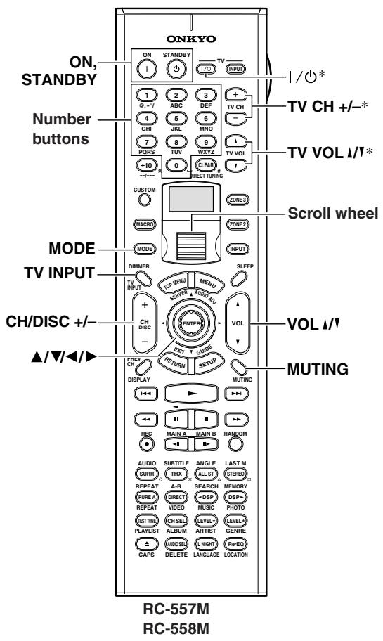
Controlling a TV
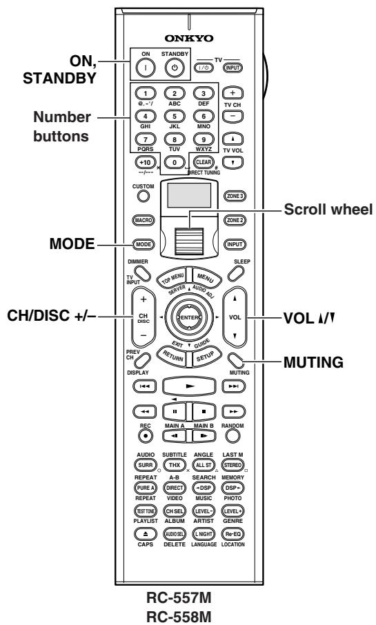
Controlling a Cable Receiver
- Roll the scroll wheel to select the input source and the remote controller mode for your TV.
Perform this operation while both the [MODE] and [INPUT] buttons are not illuminated. If you want to operate only the TV without changing the input source, press the [MODE] button and roll the scroll wheel to select "TV." - Point the remote controller at your TV, and use the following buttons (you must enter appropriate remote control code first).
| ON, STANDBY | Set the TV to On or Standby |
| TV | / ① | TV on/off |
| TV CH +/- | Select TV channels |
| Number buttons | Enter numbers |
| CH/DISC +/- | Select cable channels |
| TV INPUT | Select TV or VCR input |
| TV VOL ↑/↑ | Adjust the TV volume |
- Buttons marked with an asterisk can always be used to control a TV regardless of the currently selected remote controller mode. These buttons do not work with the additional TV modes.
The following buttons control the TX-NR1000/TX-NR5000E.
| VOL ↓/↑ | Adjust the TX-NR1000/TX-NR5000E volume |
| MUTING | Mute the TX-NR1000/TX-NR5000E |
- Roll the scroll wheel to select the input source and the remote controller mode for your cable receiver.
Perform this operation while both the [MODE] and [INPUT] buttons are not illuminated. If you want to operate only the cable receiver without changing the input source, press the [MODE] button and roll the scroll wheel to select "CBL." - Point the remote controller at your cable receiver, and use the following buttons (you must enter appropriate remote control code first).
| ON, STANDBY | Set the cable receiver to On or Standby |
| CH/DISC +/- | Select cable channels |
| Number buttons | Enter numbers |
The following buttons control the TX-NR1000/ TX-NR5000E.
| VOL ↓/↑ | Adjust the TX-NR1000/TX-NR5000E volume |
| MUTING | Mute the TX-NR1000/TX-NR5000E |
Learning Commands from Another Remote Controller
You can teach the TX-NR1000/TX-NR5000E's remote controller new commands simply by transmitting commands from another remote controller one at a time. For example, by transmitting the Play and Stop commands from your CD player's remote controller, the TX-NR1000/TX-NR5000E's remote controller can be taught to transmit those commands when its Play [▶] and Stop [■] buttons are pressed in CD mode. This is convenient when you want to add commands to buttons after entering a remote control code (See page 129).
| 1 CUSTOM | Press and hold the [CUSTOM] button for more than three seconds. The remote controller enters Custom mode. |
| 2 | Roll the scroll wheel to select "LEARN," and then press the scroll wheel. |
| 3 | Roll the scroll wheel to select the remote controller mode you want to teach a new command, and then press the scroll wheel. |
| 4 | On the TX-NR1000/TX-NR5000E's remote controller, press the button you want to teach the new command. RETRY If you press a button that cannot be taught a new command, the message "RETRY" appears and you should press another button. |
| 5 | Point the remote controllers at each other, about 2 to 6 inches (5-15 cm) apart, and then, on the other remote controller, press the button whose command you want to learn. When the command has been learned successfully, “OK” appears on the display. You may need to press the button several times. If the command is not learned successfully, after the message “FAIL” has been displayed, the mode select display reappears (step 3), and you should try again. |
| 6 | To teach the TX-NR1000/ TX-NR5000E's remote controller more new commands, repeat steps 3 through 5. Press the [CUSTOM] button when you’ve finished. |
Notes:
- The following buttons cannot be taught new commands: [LIGHT], [CUSTOM], [MACRO], [MODE], [INPUT], [ZONE 2], [ZONE 3], and the scroll wheel button.
- The TX-NR1000/TX-NR5000E's remote controller can learn a total of 150 commands. However, the commands of some remote controllers may use a lot of memory, in which case, this total will be reduced.
- If the message "FULL" appears, the remote controller cannot learn any more commands because its memory is full.
- By default, the TX-NR1000/TX-NR5000E's remote controller knows the commands for controlling an Onkyo CD player, cassette deck, DVD player, and MD recorder (e.g., Play, Stop, Pause, etc., buttons). You can teach these buttons new commands, although the defaults will be restored if the remote controller is reset.
- To teach a new command to a button that has already been taught a command, simply repeat this procedure.
- Like most remote controllers, the TX-NR1000/ TX-NR5000E's remote controller uses infrared. Commands from remote controllers that don't use infrared cannot be learned.
- When the remote controller's batteries expire, all learned commands will be lost and will have to learned all over again, so don't discard your other remote controllers.
Using Macros
With the Macro function you can program the remote controller to perform a sequence of actions with one press of a button. For example, normally you need to perform the following actions to use a CD player that's connected to the TX-NR1000/TX-NR5000E:
- Press the scroll wheel, (to select AMP mode).
- Press the [ON] button (to turn on the TX-NR1000/TX-NR5000E).
- Roll the scroll wheel to select CD (to select the CD remote controller mode and the CD input source).
- Press the Play [▶] button (to start the CD player).
With the Macro function you can program the remote controller to do all of this with one press of a button.
Making Macros
You can make up to eight macros, and each macro can perform up to eight actions.
1
CUSTOM

Press and hold the [CUSTOM] button for more than three seconds.
The remote controller enters Custom mode.
2

Roll the scroll wheel to select "MACRO," and then press the scroll wheel.
3
Roll the scroll wheel to select "EDIT," and then press the scroll wheel.
4
Roll the scroll wheel to select a macro, and then press the scroll wheel.
Macros are numbered from 1 to 8.
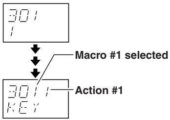
5
On the remote controller, press the buttons whose actions you want to program into the macro in the order you want them performed.
To program the CD example in the left column into a macro: press the scroll wheel, press the [ON] button, roll the scroll wheel to select CD, press the scroll wheel, and then press the Play

bu
ton.
Actions are numbered from 1 to 8.
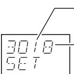
Macro #1 selected
8 actions learned
After each button is pressed, "SET" followed by "KEY" is displayed.
To add an action that selects an input source for the main room, Zone 2, or Zone 3, press the [INPUT], [ZONE 2], or [ZONE 3] button, respectively, roll the scroll wheel to select the input source, and then press the scroll wheel.
6
When you've finished, press the Macro button.
After the following appears on the display, the display returns to normal.
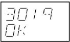
Running Macros
Programmed macros can be run as follows.
| 1 | Press the [MACRO] button. |
| 2 | Roll the scroll wheel to select the macro's number, and then press the scroll wheel. The actions in the macro are performed in the order in which they were programmed. |
Naming Macros
You can name your macros as follows. Names may contain of up to five characters.
| 1 CUSTOM | Press and hold the [CUSTOM] button for more than three seconds. The remote controller enters Custom mode. |
| 3 MACRO |
2 Roll the scroll wheel to select "MACRO," and then press the scroll wheel.
3 Roll the scroll wheel to select "NAME," and then press the scroll wheel.
4 Roll the scroll wheel to select the number of the macro that you want to name, and then press the scroll wheel. 1st character
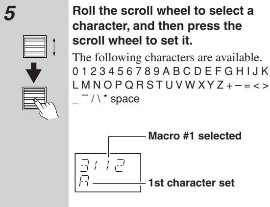
6 Repeat step 5 until you've entered all 5 characters. The previous menu reappears. If the name you are entering consists of less than five characters, enter spaces at the end to the end to fill all five places.
Other Settings for the Remote Controller
Editing Remote Controller Modes
Adding New Remote Controller Modes
You can add additional modes (DVD, TV, VCR, CBL, SAT) to the remote controller. This is useful if, for example, you have several DVD players or TVs.

Press and hold the [CUSTOM] button for more than three seconds.
The remote controller enters Custom mode.
2
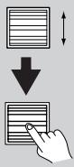
Roll the scroll wheel to select "MODE," and then press the scroll wheel.
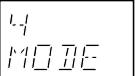
3
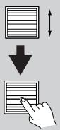
Roll the scroll wheel to select "ADD," and then press the scroll wheel.
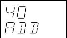
4
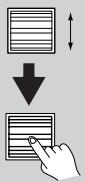
Roll the scroll wheel to select the type of mode you want to add, and then press the scroll wheel.
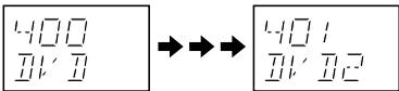
You can add up to 8 additional modes: for example, 4 DVD, 2 TV, 1 VCR, and 1 CBL.
Reordering the Remote Controller Modes
You can change the order in which the remote controller modes appear when you roll the scroll wheel. The position of the AMP mode cannot be changed.

Press and hold the [CUSTOM] button for more than three seconds.
The remote controller enters Custom mode.
2

Roll the scroll wheel to select "MODE," and then press the scroll wheel.
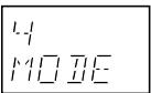
3
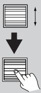
Roll the scroll wheel to select "SORT," and then press the scroll wheel.
4

Roll the scroll wheel to select the mode you want to move, and then press the scroll wheel.
5
Roll the scroll wheel to select the mode before which you want to insert the specified mode, and then press the scroll wheel.
Here the specified mode will be inserted before the "VCR" mode.
If the move is successful, after "OK" has been displayed, the SORT display (step 3) reappears.
Deleting Remote Controller Modes
You can delete remote controller modes that you don't need, such as modes for components that you don't have. The AMP mode cannot be deleted.
| 1 CUSTOM | Press and hold the [CUSTOM] button for more than three seconds. The remote controller enters Custom mode. |
| 2 | Roll the scroll wheel to select “MODE,” and then press the scroll wheel. |
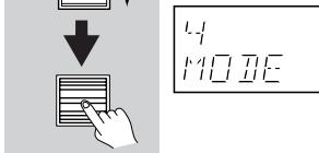
| 3 | Roll the scroll wheel to select “DEL,” and then press the scroll wheel. |
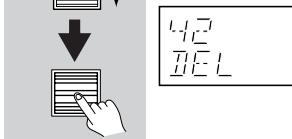
| 4 | Roll the scroll wheel to select the mode you want to delete, and then press the scroll wheel. |
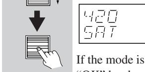
play (step 3) reappears.
4
Assigning Remote Controller Modes
You can change the combination in selecting the input source and remote controller mode simultaneously using the scroll wheel. For example, when the input source (top) is "TAPE1" and the remote controller mode (bottom) is "AMP," you can change only "AMP"(the remote controller mode) to "CDR."
1 Press and hold the [CUSTOM] button for more than three seconds.
The remote controller enters Custom mode.
2 Roll the scroll wheel to select "MODE," and then press the scroll wheel.
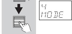
3 Roll the scroll wheel to select "ASSGN," and then press the scroll wheel.
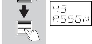
4 Roll the scroll wheel to select an input source, and then press the scroll wheel.
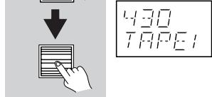
Roll the scroll wheel to select the mode you want to assign to the specified input source, and then press the scroll wheel.
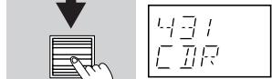
If the assignment is successful, after "OK" has been displayed, the ASSGN display (step 3) reappears.
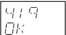
| Resetting the Remote Controller | |
| You can reset the remote controller to its default settings. | |
| 1 CUSTOM | Press and hold the [CUSTOM] button for more than three seconds. The remote controller enters Custom mode. |
| 2 | Roll the scroll wheel to select “SETUP,” and then press the scroll wheel. |
| 3 | Roll the scroll wheel to select “RESET,” and then press the scroll wheel. |
| 4 | Roll the scroll wheel to select “YES,” and then press the scroll wheel. The remote controller is reset to its default settings. |
Using the Remote Controller with Radio Frequency (RC-558M only)
You can set the remote controller's transmission signal format to either infrared (IR) or radio frequency (RF).
The default setting is IR.
This is useful when, for example, the TX-NR1000/ TX-NR5000E is installed in a rack or is not in line of sight of the remote controller as it allows you to use a commercially available RF receiver to pick up commands from the remote controller, which are then fed to the TX-NR1000/TX-NR5000E via its IR IN socket. For this to work, you must assign the same ID and channel to the remote controller and RF receiver.
| 1 CUSTOM | Press and hold the [CUSTOM] button for more than three seconds. The remote controller enters Custom mode. |
| 2 | Roll the scroll wheel to select “SETUP,” and then press the scroll wheel. |
| 3 | Roll the scroll wheel to select “IR/ RF,” and then press the scroll wheel. |
| 4 | Roll the scroll wheel to select “IR” or “RF,” and then press the scroll wheel. When you select “IR.” |
| 5 | If you select “RF,” roll the scroll wheel to select the same ID as the RF receiver, and then press the scroll wheel. IDs 0 to 9 and A to F can be selected. |
| 6 | Roll the scroll wheel to select the same channel as the RF receiver, and then press the scroll wheel. Channels 0 to 3 can be selected. If the ID and channel have been set successfully, “OK” appears on the display. |
Changing the Remote Controller's Control ID
This section explains how to change the remote controller's ID. You may need to change this if the TX-NR1000/TX-NR5000E's remote controller interferes with other Onkyo components located in the same room.
Note:
If you change the remote controller's ID, be sure to select the same ID on the TX-NR1000/TX-NR5000E. For details on setting up the TX-NR1000/ TX-NR5000E's remote control ID, refer to the "Remote Control Setup Sub-menu" section on page 87. The default ID for both the TX-NR1000/TX-NR5000E and remote controller is 1.
1 Hold down the remote controller's [CUS-TOM] button for more than three seconds. The remote controller enters Custom mode.
2 Roll the scroll wheel to select "SETUP" menu, and then press the scroll wheel.
3 Roll the scroll wheel to select ID menu, and then press the scroll wheel.
4 Roll the scroll wheel to select an ID—1 (default), 2, or 3—and then press the scroll wheel. Select the same ID as that set on the TX-NR1000/TX-NR5000E.
Relationship Between Input Source and Listening Mode
| Button | Input Signal Format | PCM | Dolby Digital | Dolby Digital/AAC | AAC | Analog Multichannel | ||||
| Multichannel(*/2) | Multichannel(Other than*) | 2ch | 1/0 | 1+1 | 5.1ch | 7.1ch | ||||
| Type of sourceListening mode | CD, TV, LD,VHS, MD,Vinyl, Radio,Cassette, Cable,Satellite, etc. | DVD, Digital cable/satellite, etc. | DVD-Audio, Super Audio CD | |||||||
| DIRECT | Direct | ✓ | ✓ | ✓ | ✓ | ✓ | ✓ | ✓ | ✓ | |
| PURE A | Pure Audio | ✓ | ✓ | ✓ | ✓ | ✓ | ✓ | ✓ | ✓ | |
| STEREO | Stereo | ✓ | ✓ | ✓ | ✓ | ✓ | ✓ | ✓ | ✓ | |
| Multiplex | ||||||||||
| SURROUND | Dolby Pro Logic II | • PLII Movie | ✓ | ✓ | ||||||
| • PLII Music | ✓ | ✓ | ||||||||
| • PLII Game | ✓ | ✓ | ||||||||
| Dolby Pro Logic IIx | • PLIIx Movie | ✓ | ✓ | ✓ | ✓ | |||||
| • PLIIx Music | ✓ | ✓ | ✓ | ✓ | ||||||
| • PLIIx Game | ✓ | ✓ | ||||||||
| Dolby Digital/AAC | ✓ | ✓ | ||||||||
| Dolby VS | ✓ | ✓ | ✓ | ✓ | ✓ | ✓ | ✓ | |||
| Dolby Digital EX/Dolby EX | ✓ | ✓ | ||||||||
| DTS | ||||||||||
| DTS 96/24 | ||||||||||
| DTS-ES Discrete | ||||||||||
| DTS-ES Matrix | ||||||||||
| DTS NEO:6 (NEO:6 Matrix) | ✓ | ✓ | ||||||||
| • NEO:6 Cinema | ✓ | ✓ | ||||||||
| • NEO:6 Music | ✓ | ✓ | ||||||||
| Multichannel | ✓ | ✓ | ||||||||
| i.LINK(IEEE1394):DVD-Audio | ||||||||||
| i.LINK(IEEE1394):SACD | ||||||||||
| THX | THX • THX Cinema | ✓ | ✓ | ✓ | ✓ | ✓ | ✓ | |||
| • THX Ultra2 Cinema | ✓ | ✓ | ||||||||
| • THX Music Mode | ✓ | ✓ | ||||||||
| • THX Games Mode | ✓ | ✓ | ✓ | ✓ | ✓ | ✓ | ||||
| • THX SurroundEX | ✓ | ✓ | ||||||||
| ▲DSF, DSR | Mono | ✓ | ✓ | ✓ | ✓ | ✓ | ✓ | ✓ | ✓ | |
| All Ch Stereo | ✓ | ✓ | ✓ | ✓ | ✓ | ✓ | ✓ | ✓ | ||
| Full Mono | ✓ | ✓ | ✓ | ✓ | ✓ | ✓ | ✓ | ✓ | ||
| Mono Movie | ✓ | ✓ | ✓ | ✓ | ✓ | ✓ | ✓ | ✓ | ||
| Enhance | ✓ | ✓ | ✓ | ✓ | ✓ | ✓ | ✓ | ✓ | ||
| Orchestra | ✓ | ✓ | ✓ | ✓ | ✓ | ✓ | ✓ | ✓ | ||
| Unplugged | ✓ | ✓ | ✓ | ✓ | ✓ | ✓ | ✓ | ✓ | ||
| Studio-Mix | ✓ | ✓ | ✓ | ✓ | ✓ | ✓ | ✓ | ✓ | ||
| TV Logic | ✓ | ✓ | ✓ | ✓ | ✓ | ✓ | ✓ | ✓ | ||
| Button | Input Signal Format | DTS | DTS96/24 | Discrete/Matrix | ||||||||
| Multichannel(*/2) | Multichannel(Other than*) | 2/0 | 1/0 | Multichannel(*/2) | Multichannel(Other than*) | Matrix | 2ch | 1/0 | ||||
| Type of source Listening mode | DVD, LD, CD, etc. | |||||||||||
| DIRECT | Direct | ✓ | ✓ | ✓ | ✓ | ✓ | ✓ | ✓ | ✓ | ✓ | ✓ | |
| PURE A | Pure Audio | ✓ | ✓ | ✓ | ✓ | ✓ | ✓ | ✓ | ✓ | ✓ | ✓ | |
| STEREO | Stereo | ✓ | ✓ | ✓ | ✓ | ✓ | ✓ | ✓ | ✓ | ✓ | ✓ | |
| Multiplex | ||||||||||||
| SURROUND | Dolby Pro Logic II | • PLII Movie | ✓ | ✓ | ||||||||
| • PLII Music | ✓ | ✓ | ||||||||||
| • PLII Game | ✓ | ✓ | ||||||||||
| Dolby Pro Logic IIx | • PLIIx Movie | ✓ | ✓ | ✓ | ✓ | |||||||
| • PLIIx Music | ✓ | ✓ | ✓ | ✓ | ||||||||
| • PLIIx Game | ✓ | ✓ | ||||||||||
| Dolby Digital/AAC | ||||||||||||
| Dolby VS | ✓ | ✓ | ✓ | ✓ | ✓ | ✓ | ✓ | ✓ | ✓ | |||
| Dolby Digital EX/Dolby EX | ✓ | ✓ | ||||||||||
| DTS | ✓ | ✓ | ✓ | |||||||||
| DTS 96/24 | ✓ | ✓ | ✓ | |||||||||
| DTS-ES Discrete | ✓ | |||||||||||
| DTS-ES Matrix | ✓*2 | ✓ | ||||||||||
| DTS NEO:6 (NEO:6 Matrix) | ✓ | ✓*2 | ||||||||||
| • NEO:6 Cinema | ✓ | ✓*2 | ||||||||||
| • NEO:6 Music | ✓ | ✓*2 | ||||||||||
| Multichannel | ||||||||||||
| i.LINK(IEEE1394):DVD-Audio | ||||||||||||
| i.LINK(IEEE1394):SACD | ||||||||||||
| THX | THX • THX Cinema | ✓ | ✓ | ✓ | ✓ | ✓ | ✓ | ✓ | ✓ | |||
| • THX Ultra2 Cinema | ✓ | ✓ | ✓ | ✓ | ||||||||
| • THX Music Mode | ✓ | ✓ | ✓ | ✓ | ||||||||
| • THX Games Mode | ✓ | ✓ | ✓ | ✓ | ✓ | ✓ | ✓ | ✓ | ||||
| • THX SurroundEX | ✓ | ✓ | ||||||||||
| DSP, DSP | Mono | ✓ | ✓ | ✓ | ✓ | ✓ | ✓ | ✓ | ✓ | ✓ | ✓ | |
| All Ch Stereo | ✓ | ✓ | ✓ | ✓ | ✓ | ✓ | ✓ | ✓ | ✓ | ✓ | ||
| Full Mono | ✓ | ✓ | ✓ | ✓ | ✓ | ✓ | ✓ | ✓ | ✓ | ✓ | ||
| Mono Movie | ✓ | ✓ | ✓ | ✓ | ✓ | ✓ | ✓ | ✓ | ✓ | ✓ | ||
| Enhance | ✓ | ✓ | ✓ | ✓ | ✓ | ✓ | ✓ | ✓ | ✓ | ✓ | ||
| Orchestra | ✓ | ✓ | ✓ | ✓ | ✓ | ✓ | ✓ | ✓ | ✓ | ✓ | ||
| Unplugged | ✓ | ✓ | ✓ | ✓ | ✓ | ✓ | ✓ | ✓ | ✓ | ✓ | ||
| Studio-Mix | ✓ | ✓ | ✓ | ✓ | ✓ | ✓ | ✓ | ✓ | ✓ | ✓ | ||
| TV Logic | ✓ | ✓ | ✓ | ✓ | ✓ | ✓ | ✓ | ✓ | ✓ | ✓ | ||
*2 NEO:6-96k
| Button | Input Signal Format | i.LINK(IEEE1394):DVD-Audio | i.LINK(IEEE1394):SACD | |||||||
| Multichannel(*/2) | Multichannel(Other than*) | 2/0 | 1/0 | 1+1 | 176.4/192kHz | Multichannel(3/2) | 2/0 | |||
| Type of sourceListening mode | DVD-Audio | Super Audio CD | ||||||||
| DIRECT | Direct | ✓ | ✓ | ✓ | ✓ | ✓ | ✓ | ✓ | ✓ | |
| PURE A | Pure Audio | ✓ | ✓ | ✓ | ✓ | ✓ | ✓ | ✓ | ✓ | |
| STEREO | Stereo | ✓ | ✓ | ✓ | ✓ | ✓ | ✓ | ✓ | ✓ | |
| Multiplex | ✓ | |||||||||
| SURROUND | Dolby Pro Logic II | • PLII Movie | ✓ | ✓ | ||||||
| • PLII Music | ✓ | ✓ | ||||||||
| • PLII Game | ✓ | ✓ | ||||||||
| Dolby Pro Logic IIx | • PLIIx Movie | ✓ | ✓ | ✓ | ✓ | |||||
| • PLIIx Music | ✓ | ✓ | ✓ | ✓ | ||||||
| • PLIIx Game | ✓ | ✓ | ||||||||
| Dolby Digital/AAC | ||||||||||
| Dolby VS | ✓ | ✓ | ✓ | ✓ | ✓ | ✓ | ✓ | |||
| Dolby Digital EX/Dolby EX | ✓ | ✓ | ||||||||
| DTS | ||||||||||
| DTS 96/24 | ||||||||||
| DTS-ES Discrete | ||||||||||
| DTS-ES Matrix | ||||||||||
| DTS NEO:6 (NEO:6 Matrix) | ✓ | ✓ | ||||||||
| • NEO:6 Cinema | ✓ | ✓ | ||||||||
| • NEO:6 Music | ✓ | ✓ | ||||||||
| Multichannel | ||||||||||
| i.LINK(IEEE1394):DVD-Audio | ✓ | ✓ | ||||||||
| i.LINK(IEEE1394):SACD | ✓ | |||||||||
| THX | THX • THX Cinema | ✓ | ✓ | ✓ | ✓ | ✓ | ||||
| • THX Ultra2 Cinema | ✓ | ✓ | ||||||||
| • THX Music Mode | ✓ | ✓ | ||||||||
| • THX Games Mode | ✓ | ✓ | ✓ | ✓ | ✓ | |||||
| • THX SurroundEX | ✓ | ✓ | ||||||||
| ▲DSP, DSP | Mono | ✓ | ✓ | ✓ | ✓ | ✓ | ✓ | ✓ | ||
| All Ch Stereo | ✓ | ✓ | ✓ | ✓ | ✓ | ✓ | ✓ | |||
| Full Mono | ✓ | ✓ | ✓ | ✓ | ✓ | ✓ | ✓ | |||
| Mono Movie | ✓ | ✓ | ✓ | ✓ | ✓ | ✓ | ✓ | |||
| Enhance | ✓ | ✓ | ✓ | ✓ | ✓ | ✓ | ✓ | |||
| Orchestra | ✓ | ✓ | ✓ | ✓ | ✓ | ✓ | ✓ | |||
| Unplugged | ✓ | ✓ | ✓ | ✓ | ✓ | ✓ | ✓ | |||
| Studio-Mix | ✓ | ✓ | ✓ | ✓ | ✓ | ✓ | ✓ | |||
| TV Logic | ✓ | ✓ | ✓ | ✓ | ✓ | ✓ | ✓ | |||
Troubleshooting
If you have any trouble using your TX-NR1000/TX-NR5000E, look for a solution in this section. If you can't resolve the issue yourself, contact the dealer from whom you purchased this unit.
Power
Can't turn on the TX-NR1000/TX-NR5000E?
- Make sure that the power cord is properly plugged into the wall outlet. (USA, Canadian, and Australian models: make sure that the other end of the power cord is properly connected to the TX-NR1000/TX-NR5000E's AC INLET).
- Unplug the power cord from the wall outlet, wait five seconds or more, then plug the cable in again.
The TX-NR1000/TX-NR5000E turns off as soon as it's turned on?
- The amp protection circuit has been activated. Remove the power cord from the wall outlet immediately and contact the dealer from whom you purchased this unit.
The [STANDBY] indicator on the TX-NR1000/ TX-NR5000E remains lit?
- It is supposed that the TX-NR1000/TX-NR5000E is using a source in Zone 2 or 3. When not using, set both Zone 2 and 3 to "Off" (page 68).
External devices connected to AC OUTLET of the TX-NR1000/TX-NR5000E do not turn off even when the unit is in standby mode.
- It is supposed that the TX-NR1000/TX-NR5000E is using devices in Zone 2 or 3. When not using, set both Zone 2 and 3 to "Off."
Audio
There's no sound, or it's very quiet?
- Make sure that all audio connecting plugs are pushed in all the way.
- Make sure that the inputs and outputs of all components are connected properly (pages 88, 93).
- Make sure that the polarity of the speaker cables is correct and that the bare wires are in contact with the metal part of each speaker terminal (page 25).
- Make sure that the input source is properly selected (page 50).
- Check the volume. It can be set from -81.5 to +18 (page 50).
The TX-NR1000/TX-NR5000E is designed for home theater enjoyment. It has a wide volume range, allowing for precise adjustment.
- If the MUTING indicator is shown on the display, press the remote controller's [MUTING] button to unmute the TX-NR1000/TX-NR5000E (page 52).
While a pair of headphones is connected to the PHONES jack, no sound is output by the speakers (page 52). - Check the digital audio output setting on the connected device. On some games consoles, such as those that support DVD, the default setting is off.
- With some DVD-Video discs, you need to select an audio output format from a menu.
- Make sure that the correct input signal audio format is selected with the [AUDIO SELECTOR] button (page 55).
- To use a turntable with an MC-type cartridge requires a commercially available MC phono preamp (page 38).
-
Make sure that none of the connecting cables are bent, twisted, or damaged.
-
Not all listening modes use all of the speakers.
- Specify the Speaker/Output Setup and Input Setup (pages 88-98).
Only the front speakers produce sound?
- When the Stereo listening mode is selected, only the front speakers and subwoofer produce sound.
- When the Direct or Pure Audio listening mode is selected, only the front speakers produce sound.
- Make sure the speakers are configured correctly (page 88).
Only the center speaker produces sound?
- If you use the Pro Logic II/IIx Movie or Pro Logic II/IIx Music listening mode with a mono source, such as an AM radio station or mono TV program, the sound is concentrated in the center speaker.
- Make sure the speakers are configured correctly (page 88).
The surround speakers produce no sound?
- When the Stereo, Direct, or Pure Audio listening mode is selected, the surround speakers produce no sound (page 56).
Depending on the source and current listening mode, not much sound may be produced by the surround speakers. Try selecting another listening mode. - Make sure the speakers are configured correctly (page 88).
The center speaker produces no sound?
- When the Stereo, Direct, or Pure Audio listening mode is selected, the center speaker produces no sound (page 56).
- When the listening mode is set to "Mono," no sound can be present in the center speaker.
- Make sure the speakers are configured correctly (page 88).
The surround back speakers produce no sound?
- The surround back speakers are not used with all listening modes. Select another listening mode (page 56-58).
- Not much sound may be produced by the surround back speakers with some sources.
- If the "SB Mode (5ch)" is available in any sub-menu of the "Listening Mode Setup" menu, make sure that it is not set to "Off" (pages 102-109).
- Make sure the speakers are configured correctly (page 88).
The subwoofer produces no sound?
- When you play source material that contains no information in the LFE channel, the subwoofer produces no sound.
- Make sure the speakers are configured correctly (pages 88, 89).
There's no sound with a certain signal format?
- Check the input signal format setting. Depending on the playback source, you can select Auto, Multich, Analog, or i.LINK (page 55).
- Check the digital audio output setting on the connected device. On some games consoles, such as those that support DVD, the default setting is off.
- With some DVD-Video discs, you need to select an audio output format from a menu.
Depending on the input signal, some listening modes cannot be selected (page 143-145).
Can't select the DTS-ES Discrete/Matrix or THX Surround EX listening modes?
- These modes cannot be selected when no surround back speakers are connected, or Zone 2/3 is being used.
- If the "SB Mode (5ch)" is available in any sub-menu of the "Listening Mode Setup" menu, make sure that it is not set to "Off" (pages 102-109).
Can't get 6.1 or 7.1 playback?
- If no surround back speakers are connected, or Zone 2/3 is being used, 6.1 and 7.1 playback is not possible.
- If the "SB Mode (5ch)" is available in any sub-menu of the "Listening Mode Setup" menu, make sure that it is not set to "Off" (pages 102-109).
The volume cannot be set above 99?
- When the levels of all speakers have been calibrated (page 90), the maximum volume setting may change.
Noise can be heard?
- Using cable ties to bundle audio cables with power cords, speaker cables, and so on may degrade the audio performance, so don't do it.
- An audio cable may be picking up interference. Try repositioning your cables.
The Late Night function doesn't work?
Make sure the source material is Dolby Digital (page 54).
The multichannel input doesn't work?
- Check the MULTI-CH IN connections (page 64).
- Make sure that the multichannel input is assigned to the correct input source (page 64).
- Set the audio input signal format to Multich (page 65).
About DTS signals
- When DTS program material ends and the DTS bitstream stops, the TX-NR1000/TX-NR5000E remains in DTS listening mode and the DTS indicator remains on. This is to prevent noise when you use the pause, fast forward, or fast reverse function on your player. If you switch your player from DTS to PCM, because the TX-NR1000/ TX-NR5000E does not switch formats immediately, you may not hear any sound, in which case you should stop your player for about three seconds, and then resume playback.
- With some CD and LD players, you won't be able to playback DTS material properly even though your player is connected to a digital input on the TX-NR1000/ TX-NR5000E. This is usually because the DTS bitstream has been processed (e.g., output level, sampling rate, or frequency response changed) and the TX-NR1000/ TX-NR5000E doesn't recognize it as a genuine DTS signal. In such cases, you may hear noise.
- When playing DTS program material, using the pause, fast forward, or fast reverse function on your player may produce a short audible noise. This is not a malfunction.
Video
There's no picture?
- Make sure that all video connecting plugs are pushed in all the way.
- Make sure that each video component is properly connected.
- Make sure that the proper setting is made for the "Video Assign" sub-menu under the "Input Setup" menu (page 95).
- On your TV, make sure that the video input to which the TX-NR1000/TX-NR5000E is connected is selected.
- While the Pure Audio listening mode is selected, the video circuits are turned off and the TX-NR1000/TX-NR5000E outputs no video signals.
The onscreen menus (OSD) don't appear, or they appear in an odd position?
-
Make sure that the proper setting is made for the "Video Output Assign" sub-menu under the "Speaker/Output Setup" menu (page 92).
-
Make sure that the proper setting is made for the "OSD Setup" sub-menu under the "Preference" menu (page 119).
- On your TV, make sure that the video input to which the TX-NR1000/TX-NR5000E is connected is selected.
Tuner
Reception is noisy, FM stereo reception is noisy, or the FM STEREO indicator doesn't appear?
- Relocate your antenna.
- Move the TX-NR1000/TX-NR5000E away from your TV or computer.
- Press the [TUNING MODE] button to turn off the "AUTO" indicator, bringing the FM mode to monaural (page 60).
- When listening to an AM station, operating the remote controller may cause noise.
Passing cars and airplanes can cause interference.
Concrete walls weaken radio signals. - If nothing improves the reception, install an outdoor antenna.
When the TX-NR1000/TX-NR5000E is unplugged or a power failure occurred:
- Normally, the built-in memory retains its contents for 2 weeks. If it loses radio presets, make the presets again.
Remote Controller
The remote controller doesn't work?
- Make sure that the batteries are installed with the correct polarity (page 9).
- Install new batteries. Don't mix different types of batteries or old and new batteries (page 9).
- Make sure that the remote controller is not too far away from the TX-NR1000/TX-NR5000E, and that there's no obstruction between the remote controller and the TX-NR1000/TX-NR5000E's remote control sensor (page 9).
- Make sure that the TX-NR1000/TX-NR5000E is not subjected to direct sunshine or inverter type fluorescent lights. Relocate if necessary.
- If the TX-NR1000/TX-NR5000E is installed in a rack or cabinet with colored glass doors, the remote controller may not work reliably when the doors are closed.
- Make sure you've selected the correct remote controller mode (pages 49).
- When using the remote controller to control other manufacturers' AV components, some buttons may not work as expected.
Make sure you've entered the correct remote control ID. - If you change the remote controller's transmission signal format to RF, be sure to select the same ID as the RF receiver.
Can't control other components?
- If it's an Onkyo component, make sure that the RI cable and analog audio cable (RCA/phono) are connected properly. Connecting only an RI cable won't work (page 47).
- Make sure you've selected the correct remote controller mode (pages 47).
Can't learn commands from other remote controllers?
- Make sure that the transmitting ends of both remote controllers are pointing at each other.
- Are you trying to learn from a remote controller that cannot be used for learning? Some commands cannot be learned, especially those that transmit several instructions with a single button press.
Recording
Can't record?
- On your recorder, make sure the correct input is selected (e.g., digital or analog).
- Make sure that proper output settings are made for the connected devices. Settings are available in the "Rec Out" of the "Audio Output Assign" and "Video Output Assign" sub-menus under the "Speaker/Output Setup" menu (pages 91, 92).
Zone 2/Zone 3
Zone 2/3 has turned off?
- Was the Sleep function set? The Sleep function turns off Zone 2/3 as well as the TX-NR1000/TX-NR5000E. To set the Sleep function for Zone 2/3 only, see page 67.
There's no sound?
- Recording and Zone 3 operation uses the same circuit and therefore cannot be used at the same time. Make sure that proper settings are made for outputs. Setting is available in "Zone 2 Out" or "Zone 3 Out" of the "Audio Output Assign" and "Video Output Assign" sub-menus under the "Speaker/Output Setup" menu (pages 91, 92).
The Surr Back speaker setting doesn't appear?
- If no surround back speakers are connected, or the surround back outputs are being used with Zone 2/3, this setting is unavailable.
Net-Tune
Can't access Internet radio or the Net-Tune server?
- Check the connection between the TX-NR1000/ TX-NR5000E and the LAN port on your router or switch.
- Make sure that your modem and router are properly connected, and make sure they are both turned on.
- Make sure that the Network Setup settings are correct (page 121).
Playback stops while listening to Net-Tune tracks?
- Make sure that your computer meets the system requirements listed on page 72.
- When you download or copy large files on your computer, Net-Tune playback may be interrupted. In this case, try closing any unused programs, use a more powerful computer, or use a dedicated server computer for Net-Tune Central.
- If Net-Tune Central is serving WAV files to several clients at the same time, the network may become overloaded and playback may be interrupted. This can be resolved by preparing an Ethernet network exclusively for use with NetTune, separating it from general network traffic, and by using switches to improve network performance.
Can't get a list of Internet radio stations from the XivaNet online database?
Try again later.
Can't access music on the selected server, or can't connect to the server?
- Make sure that your computer is turned on and that Net-Tune Central is up and running.
- Add the MP3, WMA, and WAV files on your computer to the Net-Tune Central database. See the Net-Tune Central online help for details.
- Set the TX-NR1000/TX-NR5000E's POWER switch to OFF, wait five seconds, and then set it to ON again (On USA, Canadian, and Australian models, disconnect the power cord for five seconds, and then reconnect it). If that doesn't help, restart your computer.
- On the Client Sub-menu, make sure that the NTSP Port setting is set to the same port number as Net-Tune Central. Correct as necessary (page 122).
Can't select albums?
- Use Net-Tune Central to add album names to your music files.
Can't select artists?
- Use Net-Tune Central to add artist names to your music files.
Can't select by genre?
- Use Net-Tune Central to add genre names to your music files.
No playlists are available?
- Use Net-Tune Central to create some playlists.
For other Net-Tune-related issues, please see the Net-Tune FAQ on the Onkyo Web site.
Others
The sound changes when I connect my headphones?
- When a pair of headphones is connected, its listening mode changes depending on the mode that was set before it was connected.
Can't change a setting?
- Some settings are not available while using Net-Tune.
Can't use an audio adjust function?
- Some audio adjust functions can't be used with certain listening modes.
The display doesn't work?
- The display is turned off when the Pure Audio listening mode is selected.
Error Messages
"Not available with Headphones use"
Operation not allowed while a pair of headphones is connected.
"Not available in this Sp Config"
- Doesn't work with the current speaker configuration.
"Only available with Dolby D"
Can be used with only Dolby Digital.
"Not available with this signal"
Doesn't work with the current listening mode.
"Not available with Muting"
Operation not allowed because the TX-NR1000/ TX-NR5000E is currently muted.
"Not available in this Listening Mode"
- Doesn't work with the current listening mode.
"Not available with NET AUDIO use"
Operation not possible with Net Audio selected for the input source.
"Not available with Dolby Headphone Off"
- Doesn't work with the Dolby Headphone function off.
"Not available with Dolby Headphone On"
- Doesn't work with the Dolby Headphone function on.
"Not available with zone2 out in Line out"
Operation not possible with "1-8.f. Zone 2 Out" set to "Line Out."
"Not available with zone3 out in Line out"
Operation not possible with "1-8.g. Zone 3 Out" set to "Line Out."
Memory backup
The TX-NR1000/TX-NR5000E uses a battery-less memory backup system in order to retain radio presets and other settings when it is unplugged or in the case of a power failure. Although no batteries are required, the TX-NR1000/ TX-NR5000E must be plugged into an AC outlet in order to charge the backup system.
(On other than USA, Canadian, and Australian models, the TX-NR1000/TX-NR5000E's POWER switch must be set to ON in order to charge the backup system). Once it has been charged, the TX-NR1000/TX-NR5000E will retain the settings for several weeks, although this depends on the environment and time will be shorter in humid climates.
The TX-NR1000/TX-NR5000E contains a microcomputer for signal processing and control functions. In very rare situations, severe interference, noise from an external source, or static electricity may cause it to lock up. In the unlikely event that this happens, unplug the power cord from the wall outlet, wait at least five seconds, and then plug it back in again.
To reset the TX-NR1000/TX-NR5000E to its factory defaults, turn it on and, while holding down the [VIDEO 1] button, press the [STANDBY/ON] button. When the reset is complete, "CLEAR" appears on the display and the TX-NR1000/ TX-NR5000E enters Standby mode.
Onkyo is not responsible for damages (such as CD rental fees) due to unsuccessful recordings caused by the unit's malfunction. Before you record important data, make sure that the material will be recorded correctly.
Specifications
General
Power Supply Rating
North American and some
Asian models: AC 120 V, 60 Hz
European & Australian models: AC 230-240 V, 50 Hz
Asian models: AC 220-230 volts, 50Hz
Consumption Power
USA & Canadian models: 13.8 A
European & Australian models: 1,200 W
Asian models: 1,200 W
Standby Power Consumption: 3.9 W
Dimensions (W× H× D) 435× 220× 480.5mm
(171 / 8'' × 811 / 16'' × 1815 / 16)''
Weight: 33kg (72.8 lbs)
Inputs:
Audio
Multichannel (7.1ch) Inputs:2
Phono (MM): 1
Line inputs: 9 (assignable), 1 (fixed) (Video 7
the front panel)
Digital inputs Coaxial: 6
Digital inputs Optical: 6 (assignable), 1 (fixed) (Video 7
on the front panel)
Video
Composite Video inputs: 6 (assignable),
1 (fixed, on the front panel)
S Video inputs:
6 (assignable),
Component Video RCA
1 (fixed, on the front panel)
inputs:
4 (USA & Canadian models),
Component Video BNC
3 (others)
input:
1 (other than USA & Canadian
Audio and Video
HDMI inputs (19-pin): 2
Miscellaneous
2
3-IR in (1/8-inch mini-jack) for
Main, Zone 2 and Zone 3
Outputs:
Audio
Speakers A:
Front L/R, Center, Surround L/R,
Speakers B:
Surround Back L/R
Front L/R, Center, Surround L/R,
Surround Back L/R or Powered
Zone 2 L/R
Front L/R, Center, Surround L/R,
Surround Back L/R, Subwoofer
Subwoofer
Pre out B:
Headphones:
1
Line outputs:
5 (assignable to Recout, Zone 2 out
and Zone 3 out)
Digital outputs Coaxial:
2 (assignable to Recout, Zone 2 out
Digital outputs Optical:
2 (assignable to Recout, Zone 2 out
and Zone 3 out)
Video
Composite Video outputs:
3 (assignable to Monitor out A/B,
Recout, Zone 2 out and Zone 3 out)
1 (fixed, Monitor out A)
3 (assignable to Monitor out A/B
and Recout)
1 (fixed, Monitor out A)
Component Video RCA
2 (USA & Canadian models),
1 (others)
Component Video BNC
1 (other than USA & Canadian
m = 311 ;
models)
Audio and Video
HDMI output (19-pin):
1
Miscellaneous
IR out (1/8-inch mini-jack): 3 (for Main, Zone 2 and Zone 3)
12V Trigger out (1/8-inch
mini-jack): 5 (for A, B, C, D, E)
Inputs/Outputs:
Miscellaneous
i. LINK(AUDIO) (4 pin): 2
Ethernet (Net-Tune): 1
RI (1/8-inch mini-jack): 1
RS232 (9 pin D-SUB
FM: 75 ohms unbalanced
AM: Included loop antenna and external
terminal
AC Inlet: 1 (IEC type)
AC Outlets:
USA & Canadian models: 1 (Switched, 120 W 1A max.)
Asian & Australian models: 1 (Switched, 100W max.)
Amplifier Section
Power Output (All channels):
USA & Canada (FTC):
150 Watts per channel min. RMS
into 8 ohms 2 channel driven,
from 20 to 20,000Hz with no
more than 0.05% total harmonic
distortion.
200 Watts per channel min. RMS
into 6 ohms 2 channel driven, 1,000
Hz with no more than 0.1% total
harmonic distortion.
260 Watts per channel min. RMS
into 8 ohms 2 channel driven,
1,000Hz with no more than 0.1%
total harmonic distortion. [BTL]
200 Watts per channel min. RMS
into 6 ohms 2 channel driven, 1,000
Hz DIN
280 Watts per channel min. RMS
into 8 ohms 2 channel driven, 1,000
Hz DIN [BTL]
2× 240 Watts into 6 ohms, 1,000
Hz (EIAJ)
2× 350 Watts into 8 ohms,1,000
Hz (EIAJ) [BTL]
Europe (DIN):
Dynamic Power:
THD (Total Harmonic Distor
tion):
Damping Factor:
IM Distortion:
Input Sensitivity and Impedance:
Audio
2× 340W (3 ,2 channel driven)
2× 260W 4 ,2 channel driven
2× 175W (8 , 2 channel driven)
0.05% (rated power)
0.05% (1 watt output)
60 at 8 ohms
0.05% (rated power)
0.05% (1 watt output)
200 mV, 50 kΩ (AUDIO IN 1-9/
FRONT)
2.5mV 50k (PHONO MM)
200 mV, 50 kΩ (MULTI IN FR/FL/
C/SR/SL/SBR/SBL)
36mV 50k (MULTI IN SUB)
0.5 Vp-p, 75 Ω (DIGITAL IN
COAXIAL 1-6)
Video (DVD,VIDEO 1-5)
1 Vp-p, 75 Ω (Composite Video)
1 Vp-p, 75 Ω (S Video, Y signal)
0.28 Vp-p, 75 Ω (S Video, C signal)
1 Vp-p, 75 Ω (Y)
0.7 Vp-p, 75 Ω (PB/CB, PR/CR)
Output Level and Impedance:
Audio
AUDIO 1-5: 200mV 470 (Tape 1/2/Video
1/2/3 Rec Out)
100mV 470 (Zone 2/3 Out (fixed))
PRE OUT A:
1 V, 470 Ω (Zone 2/3 Out (variable))
1 V, 470 Ω (Front L/R, CENTER,
SURR L/R, SURR BACK or
Zone 2 L/R, SUB WOOFER)
1 V, 470 Ω (SUB WOOFER)
PRE OUT B:
Video
VIDEO 1-4
(Composite Video):
1 Vp-p 75 Ω (Monitor Out A/B,
Video 1/2/3 Rec Out, Zone 2/3
Out)
VIDEO 1-4
(S Video, Y signal):
1 Vp-p, 75 Ω (Monitor Out A/B,
Video 1/2/3 Rec Out)
VIDEO 1-4
(S Video, C signal):
0.28 Vp-p, 75 ohms (Monitor Out)
A/B, Video 1/2/3 Rec Out)
1 Vp-p, 75 ohms (Y)
0.7 Vp-p, 75 ohms (PB/CB, PR/CR)
120mV RMS at 1,000Hz 0.5%
THD
Frequency Response:
Audio (CD in Direct mode)
5Hz - 100kHz .. +1 / - 3 dB
10Hz - 50MHz .. +1 / - 3 dB
Video Component
20-20 kHz: ±0.8 dB
RIAA Deviation:
± 12 dB at 50Hz (Bass)
± 12 dB at 1,000Hz (Mid)
± 12 dB at 20,000Hz (Treble)
S/N (Direct mode):
80 dB (PHONO, IHF A, 5 mV)
input)
95 dB (LINE, IHFA, 0.5V input)
Due to setup menu
Tuner Section
FM
Tuning frequency Range:
USA & Canadian models:
87.50 to 108.00 MHz, 200 kHz
steps
87.50 to 108.00 MHz, 50 kHz steps
Other models:
Usable Sensitivity:
17.2 dBf, 2.0 V (75Ω IHF)
23 V (75Ω DIN)
11.2 dBf, 1.0 V (75Ω IHF)
0.9 V (75Ω DIN)
Mono
50 dB Quieting Sensitivity:
Mono
Stereo
17.2 dBf, 2.0 V (75 ohms)
37.2 dBf, 20.0 V (75 ohms)
2.0 dB
85 dB (UDD, UDC: 40dB)
90 dB
Rejection Ratio:
N
Mono
76 dB, IHF
70 dB.IHF
Stereo
Alternate Channel Attenuation:
Mono
Selectivity:
55 dB IHF
50 dB DIN
AM Suppression Ratio:
50 dB
Harmonic Distortion:
Mono
Stereo
0.2%
0.3%
Frequency Response:
30 to 15,000Hz, + / - 1.0 dB
45 dB at 1,000 Hz
30 dB at 100 to 10,000Hz
17.2 dBf, 2.0 V (75Ω)
AM
Tuning frequency Range:
USA & Canadian models: 530 to 1710kHz 10kHz steps
European & Australian models:522 to 1611kHz 9kHz steps
Asian models: 522 to 1611kHz 9kHz steps or
530 to 1710kHz 10kHz steps
*selectable
Usable Sensitivity:
Image Rejection Ratio:
IF Rejection Ratio:
S/N:
THD:
0.7%
Specifications and features are subject to change without
notice.
ONKYO CORPORATION
Sales & Product Planning Div. : 2-1, Nisshin-cho, Neyagawa-shi, OSAKA 572-8540, JAPAN
Tel: 072-831-8023 Fax: 072-831-8124
18 Park Way, Upper Saddle River, N.J. 07458, U.S.A.
Tel: 201-785-2600 Fax: 201-785-2650 http://www.onkyousa.com
ONKYO EUROPE ELECTRONICS GmbH
Liegnitzerstrasse 6, 82194 Groebenzell, GERMANY
Tel: +49-8142-4401-0 Fax: +49-8142-4401-555 http://www.onkyo.net
ONKYO EUROPE UK Office
Suite 1, Gregories Court, Gregories Road, Beaconsfield, Buckinghamshire, HP9 1HQ
UNITED KINGDOM Tel: +44-(0)1494-681515 Fax: +44(0)-1494-680452
ONKYO CHINA LIMITED
Units 2102-2107, Metroplaza Tower I, 223 Hing Fong Road, Kwai Chung,
N.T., HONG KONG Tel: 852-2429-3118 Fax: 852-2428-9039

Printed in Japan
D0409-1