TX-DS595 - AV receiver ONKYO - Free user manual and instructions
Find the device manual for free TX-DS595 ONKYO in PDF.
| Product type | Audio-video receiver |
| Brand | ONKYO |
| Model | TX-DS595 |
| Dimensions (W x H x D) | 435 mm x 150 mm x 340 mm |
| Weight | 11 kg |
| Power supply | 120 V AC, 60 Hz |
| Power consumption | 400 W |
| Output power | 5 x 100 W (stereo, 8 ohms) |
| Number of channels | 5.1 |
| Supported audio formats | Dolby Digital, DTS, Dolby Pro Logic |
| Built-in tuner | AM/FM with 30 presets |
| Audio inputs | 6 analog inputs (CD, DVD, etc.), 2 optical, 1 coaxial |
| Video inputs | Composite and S-Video |
| Outputs | 5 speakers, 1 subwoofer pre-out, headphones, VCR |
| Maintenance and cleaning | Dust with a soft, dry cloth. Do not use solvents. |
| Safety | Polarized plug to prevent electric shock. Unplug before cleaning. |
| Spare parts and repairability | Contact an ONKYO authorized technician for any repairs. |
| Included accessories | Remote control, batteries, AM antenna, FM antenna, user manual |
Frequently Asked Questions - TX-DS595 ONKYO
User questions about TX-DS595 ONKYO
0 question about this device. Answer the ones you know or ask your own.
Ask a new question about this device
Download the instructions for your AV receiver in PDF format for free! Find your manual TX-DS595 - ONKYO and take your electronic device back in hand. On this page are published all the documents necessary for the use of your device. TX-DS595 by ONKYO.
USER MANUAL TX-DS595 ONKYO
Thank you for purchasing the Onkyo AV Receiver. Please read this manual thoroughly before making connections and plugging in the unit. Following the instructions in this manual will enable you to obtain optimum performance and listening enjoyment from your new AV Receiver. Please retain this manual for future reference.
Contents
Before using
Important Safeguards 2
Precautions 3
Features 4
Supplied accessories 4
Before using this unit 5
Facilities and connections
Front panel facilities 6
Remote controller 8
Connections 10
Connecting speakers 14
Connecting the power 16
Connecting antennas. 17
Setup and operation
Speaker setup 19
Listening to Radio Broadcasts. 21
Listening to RDS broadcasts (European models only) 23
Enjoying music or videos with TX-DS595 ... 25
Using listening mode 28
Input Setup. 29
Preference 32
Recording 33
Remote controller
Using remote controller. 34
Learning a pre-programming code 38
Operating your programmed remote controller 40
Programming the commands of remote controllers for other devices into the remote controller .... 42
Using a Macro function 45
Appendix
Specifications 49
Troubleshooting guide 50
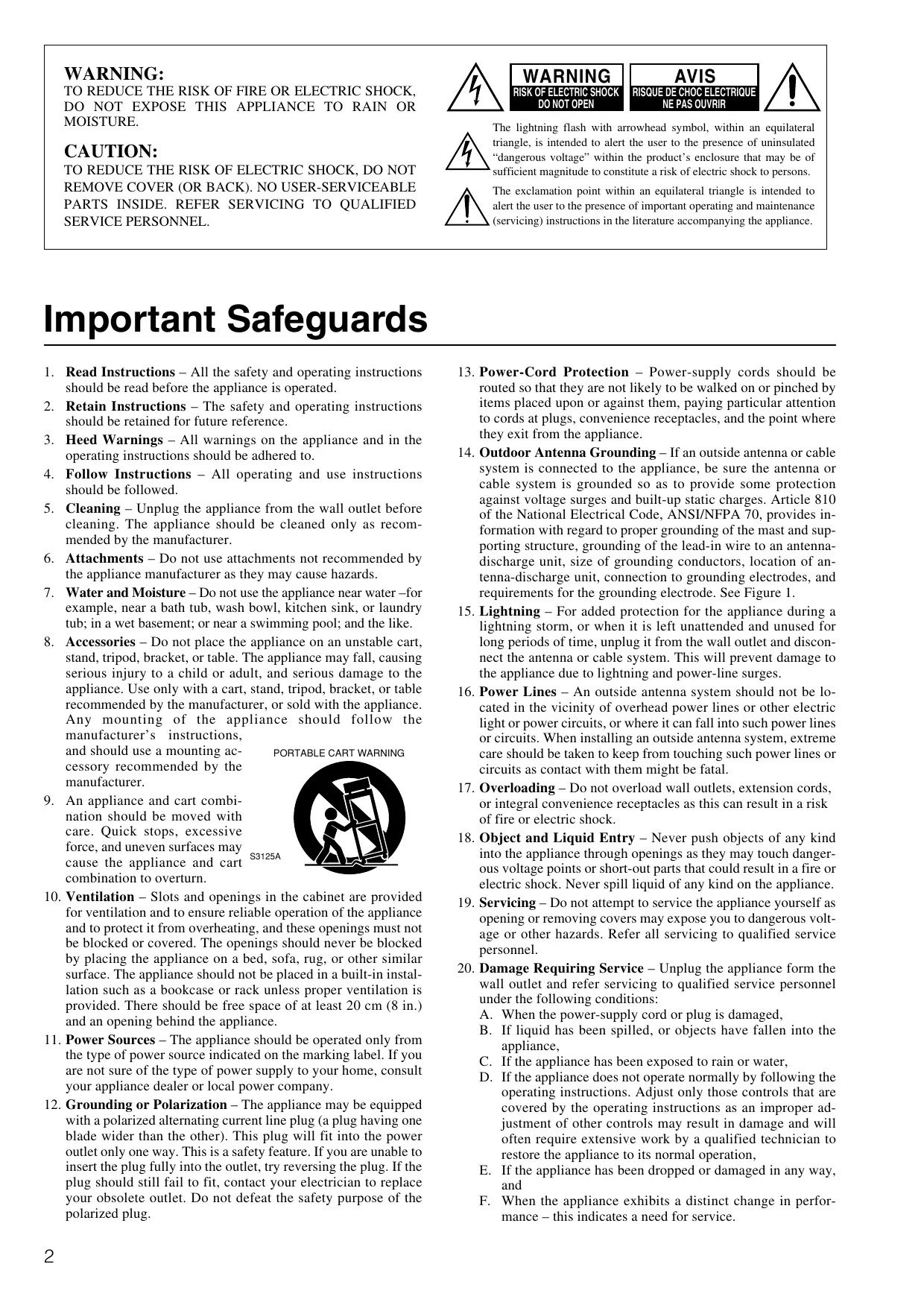
WARNING:
TO REDUCE THE RISK OF FIRE OR ELECTRIC SHOCK, DO NOT EXPOSE THIS APPLIANCE TO RAIN OR MOISTURE.
CAUTION:
TO REDUCE THE RISK OF ELECTRIC SHOCK, DO NOT REMOVE COVER (OR BACK). NO USER-SERVICEABLE PARTS INSIDE. REFER SERVICING TO QUALIFIED SERVICE PERSONNEL.
WARNING RISK OF ELECTRIC SHOCK DO NOT OPEN


The lightning flash with arrowhead symbol, within an equilateral triangle, is intended to alert the user to the presence of uninsulated "dangerous voltage" within the product's enclosure that may be of sufficient magnitude to constitute a risk of electric shock to persons.

The exclamation point within an equilateral triangle is intended to alert the user to the presence of important operating and maintenance (servicing) instructions in the literature accompanying the appliance.
Important Safeguards
- Read Instructions - All the safety and operating instructions should be read before the appliance is operated.
- Retain Instructions - The safety and operating instructions should be retained for future reference.
- HeedWarnings - All warnings on the appliance and in the operating instructions should be adhered to.
- Follow Instructions - All operating and use instructions should be followed.
- Cleaning - Unplug the appliance from the wall outlet before cleaning. The appliance should be cleaned only as recommended by the manufacturer.
- Attachments - Do not use attachments not recommended by the appliance manufacturer as they may cause hazards.
- Water and Moisture - Do not use the appliance near water –for example, near a bath tub, wash bowl, kitchen sink, or laundry tub; in a wet basement; or near a swimming pool; and the like.
- Accessories - Do not place the appliance on an unstable cart, stand, tripod, bracket, or table. The appliance may fall, causing serious injury to a child or adult, and serious damage to the appliance. Use only with a cart, stand, tripod, bracket, or table recommended by the manufacturer, or sold with the appliance. Any mounting of the appliance should follow the manufacturer's instructions,
and should use a mounting accessory recommended by the manufacturer.
PORTABLE CART WARNING

-
An appliance and cart combination should be moved with care. Quick stops, excessive force, and uneven surfaces may cause the appliance and cart combination to overturn.
-
Ventilation – Slots and openings in the cabinet are provided for ventilation and to ensure reliable operation of the appliance and to protect it from overheating, and these openings must not be blocked or covered. The openings should never be blocked by placing the appliance on a bed, sofa, rug, or other similar surface. The appliance should not be placed in a built-in installation such as a bookcase or rack unless proper ventilation is provided. There should be free space of at least 20~cm (8 in.) and an opening behind the appliance.
- Power Sources - The appliance should be operated only from the type of power source indicated on the marking label. If you are not sure of the type of power supply to your home, consult your appliance dealer or local power company.
-
Grounding or Polarization - The appliance may be equipped with a polarized alternating current line plug (a plug having one blade wider than the other). This plug will fit into the power outlet only one way. This is a safety feature. If you are unable to insert the plug fully into the outlet, try reversing the plug. If the plug should still fail to fit, contact your electrician to replace your obsolete outlet. Do not defeat the safety purpose of the polarized plug.
-
Power-Cord Protection - Power-supply cords should be routed so that they are not likely to be walked on or pinched by items placed upon or against them, paying particular attention to cords at plugs, convenience receptacles, and the point where they exit from the appliance.
- Outdoor Antenna Grounding - If an outside antenna or cable system is connected to the appliance, be sure the antenna or cable system is grounded so as to provide some protection against voltage surges and built-up static charges. Article 810 of the National Electrical Code, ANSI/NFPA 70, provides information with regard to proper grounding of the mast and supporting structure, grounding of the lead-in wire to an antenna-discharge unit, size of grounding conductors, location of antenna-discharge unit, connection to grounding electrodes, and requirements for the grounding electrode. See Figure 1.
- Lightning - For added protection for the appliance during a lightning storm, or when it is left unattended and unused for long periods of time, unplug it from the wall outlet and disconnect the antenna or cable system. This will prevent damage to the appliance due to lightning and power-line surges.
- Power Lines - An outside antenna system should not be located in the vicinity of overhead power lines or other electric light or power circuits, or where it can fall into such power lines or circuits. When installing an outside antenna system, extreme care should be taken to keep from touching such power lines or circuits as contact with them might be fatal.
- Overloading - Do not overload wall outlets, extension cords, or integral convenience receptacles as this can result in a risk of fire or electric shock.
- Object and Liquid Entry – Never push objects of any kind into the appliance through openings as they may touch dangerous voltage points or short-out parts that could result in a fire or electric shock. Never spill liquid of any kind on the appliance.
- Servicing - Do not attempt to service the appliance yourself as opening or removing covers may expose you to dangerous voltage or other hazards. Refer all servicing to qualified service personnel.
- Damage Requiring Service – Unplug the appliance form the wall outlet and refer servicing to qualified service personnel under the following conditions:
A. When the power-supply cord or plug is damaged,
B. If liquid has been spilled, or objects have fallen into the appliance,
C. If the appliance has been exposed to rain or water,
D. If the appliance does not operate normally by following the operating instructions. Adjust only those controls that are covered by the operating instructions as an improper adjustment of other controls may result in damage and will often require extensive work by a qualified technician to restore the appliance to its normal operation,
E. If the appliance has been dropped or damaged in any way, and
F. When the appliance exhibits a distinct change in performance – this indicates a need for service.
- Replacement Parts - When replacement parts are required, be sure the service technician has used replacement parts specified by the manufacturer or have the same characteristics as the original part. Unauthorized substitutions may result in fire, electric shock, or other hazards.
- Safety Check - Upon completion of any service or repairs to the appliance, ask the service technician to perform safety checks to determine that the appliance is in proper operation condition.
- Wall or Ceiling Mounting – The appliance should be mounted to a wall or ceiling only as recommended by the manufacturer.
- Heat - The appliance should be situated away from heat sources such as radiators, heat registers, stoves, or other appliances (including amplifiers) that produce heat.
Precautions
1. Warranty Claim
You can find the serial number on the rear panel of this unit. In case of warranty claim, please report this number.
2. Recording Copyright
Recording of copyrighted material for other than personal use is illegal without permission of the copyright holder.
3. AC Fuse
The fuse is located inside the chassis and is not user-serviceable. If power does not come on, contact your Onkyo authorized service station.
4. Care
From time to time you should wipe the front and rear panels and the cabinet with a soft cloth. For heavier dirt, dampen a soft cloth in a weak solution of mild detergent and water, wring it out dry, and wipe off the dirt. Following this, dry immediately with a clean cloth. Do not use rough material, thinners, alcohol or other chemical solvents or cloths since these could damage the finish or remove the panel lettering.
5. Power
WARNING
BEFORE PLugging IN THE UNIT FOR THE FIRST TIME, READ THE FOLLOWING SECTION CAREFULLY.
The voltage of the available power supply differs according to country or region. Be sure that the power supply voltage of the area where this unit will be used meets the required voltage (e.g., AC 230V , 50Hz or AC 120V , 60Hz ) written on the rear panel.
Worldwide models are equipped with a voltage selector to conform to local power supplies. Be sure to set this switch to match the voltage of the power supply in your area before plugging in the unit.
For British models
Replacement and mounting of an AC plug on the power supply cord of this unit should be performed only by qualified service personnel.
IMPORTANT
The wires in the mains lead are coloured in accordance with the following code:
Blue : Neutral
Brown : Live
As the colours of the wires in the mains lead of this apparatus may not correspond with the coloured markings identifying the terminals in your plug, proceed as follows:
The wire which is coloured blue must be connected to the terminal which is marked with the letter N or coloured black.
The wire which is coloured brown must be connected to the terminal which is marked with the letter L or coloured red.
IMPORTANT
A 5 ampere fuse is fitted in this plug. Should the fuse need to be replaced, please ensure that the replacement fuse has a rating of 5 amperes and that it is approved by ASTA or BSI to BS1362. Check for the ASTA mark or the BSI mark on the body of the fuse.
IF THE FITTED MOULDED PLUG IS UNSUITABLE FOR THE SOCKET OUTLET IN YOUR HOME THEN THE FUSE SHOULD BE REMOVED AND THE PLUG CUT OFF AND DISPOSED OF SAFELY. THERE IS A DANGER OF SEVERE ELECTRICAL SHOCK IF THE CUT OFF PLUG IS INSERTED INTO ANY 13 AMPERE SOCKET.
If in any doubt, consult a qualified electrician.
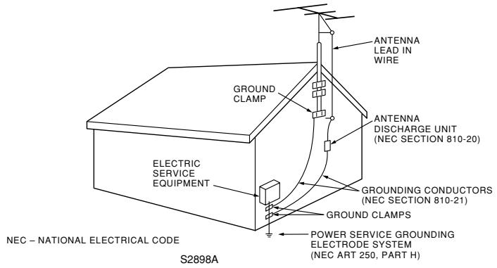
FIGURE 1: EXAMPLE OF ANTENNA GROUNDING AS PER NATIONAL ELECTRICAL CODE, ANSI/NFPA 70
For U.S. models
Note to CATV system installer:
This reminder is provided to call the CATV system installer's attention to Section 820-40 of the NEC which provides guidelines for proper grounding and, in particular, specifies that the cable ground shall be connected to the grounding system of the building, as close to the point of cable entry as practical.
FCC Information for User
CAUTION:
The user changes or modifications not expressly approved by the party responsible for compliance could void the user's authority to operate the equipment.
NOTE:
This equipment has been tested and found to comply with the limits for a Class B digital device, pursuant to Part 15 of the FCC Rules. These limits are designed to provide reasonable protection against harmful interference in a residential installation. This equipment generates, uses and can radiate radio frequency energy and, if not installed and used in accordance with the instructions, may cause harmful interference to radio communications. However, there is no guarantee that interference will not occur in a particular installation. If this equipment does cause harmful interference to radio or television reception, which can be determined by turning the equipment off and on, the user is encouraged to try to correct the interference by one or more of the following measures:
- Reorient or relocate the receiving antenna.
- Increase the separation between the equipment and receiver.
- Connect the equipment into an outlet on a circuit different from that to which the receiver is connected.
- Consult the dealer or an experienced radio/TV technician for help.
For Canadian models
NOTE:
THIS CLASS B DIGITAL APPARATUS COMPLIES WITH CANADIAN ICES-003.
For models having a power cord with a polarized plug:
CAUTION: TO PREVENT ELECTRIC SHOCK, MATCH WIDE BLADE OF PLUG TO WIDE SLOT, FULLY INSERT.
75 Watts minimum of continuous RMS power to each of the five channels into 8 from 20 Hz to 20 kHz with no more than 0.08% THD (USA models, FTC rating)
110 Watts minimum of continuous RMS power to each of the five channels into 6 Ω at 1 kHz (European models, DIN)
140 Watts minimum to each of the five channels into 6 Ω at 1kHz (Asian models, EIAJ)
Wide Range Amplifier Technology (WRAT)
Extended Frequency Response (10 Hz to 100 kHz)
Optimum Gain Volume Circuitry
Dolby* Digital, DTS, Dolby Pro Logic II decoding
A-Form Listening Mode Memory
- Manufactured under license from Dolby Laboratories. "Dolby", "Pro Logic" and the double-D symbol are trademarks of Dolby Laboratories. Confidential Unpublished Works. ©1992-1997 Dolby Laboratories, Inc. All rights reserved.
- Re-Equalization and the "Re-EQ" logo are trademarks of Lucasfilm Ltd. Manufactured under license of Lucasfilm Ltd.
- Manufactured under license from Digital Theater Systems, Inc. US Pat. No.5,451,942 and other worldwide patents issues and pending. "DTS" and "DTS Digital Surround" are trademarks of Digital Theater Systems, Inc. © 1996 Digital Theater Systems, Inc. All rights reserved.
Non-Scaling Configuration
Cinema Re-EQ™
Late night mode (high, low, off)
5.1-Channel input
4 Assignable digital inputs (2 coaxial, 2 optical)
Smart Scan Navigator with LEDs
40 FM/AM random presets
IntelliVolume
■ Powerful programmed/learning remote with macros and mode-key LEDs
Supplied accessories
Check that the following accessories are supplied with the TX-DS595.
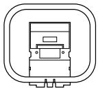
AM loop antenna × 1

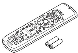
Remote controller × 1 Batteries (AA, R6 or UM-3) × 2
FM indoor antenna × 1 (connector will vary depending on model specifications)
75/300Ω antenna adapter × 1 (For all models other than USA, Canadian and European models)
Declaration of Conformity
We, ONKYO EUROPE ELECTRONICS GmbH INDUSTRIESTRASSE 20 82110 GERMERING, GERMANY

declare in own responsibility, that the ONKYO product described in this instruction manual is in compliance with the corresponding technical standards such as EN60065, EN55013, EN55020 and EN61000-3-2, -3-3 (or EN60555-2, -3)
GERMERING, GERMANY

ONKYO EUROPE ELECTRONICS GmbH
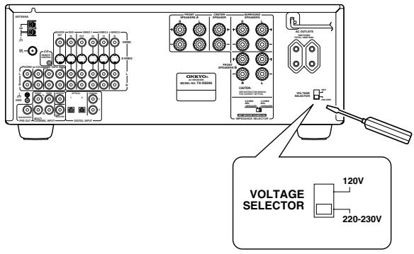
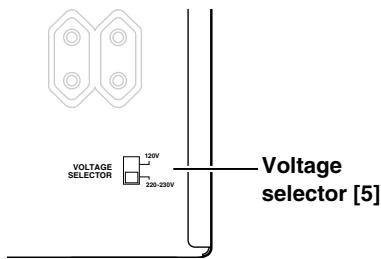
Setting the Voltage selector (Worldwide models only)
Worldwide models are equipped with a voltage selector to conform with local power supplies. Be sure to set this switch to match the voltage of the power supply in your area before plugging in the unit. Determine the proper voltage for your area: 220 - 230V or 120V . If the preset voltage is not correct for your area, insert a screwdriver into the groove in the switch. Slide the switch all the way to the upper (120V) or to the lower (220 - 230V) , whichever is appropriate.
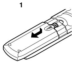
Installing the remote controller batteries
- Remove the battery compartment cover by pressing and sliding the cover.
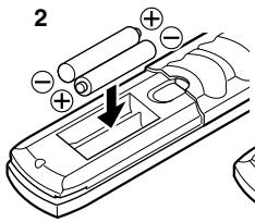
- Insert two AA (R6 or UM-3) batteries into the battery compartment. Carefully follow the polarity diagram (positive (+) and negative (-) symbols) inside the battery compartment.
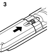
- After batteries are installed and seated correctly, replace the compartment cover.
Notes:
- Do not mix new batteries with old batteries or different kinds of batteries.
- To avoid corrosion, remove the batteries if the remote controller is not to be used for a long time.
- Remove dead batteries immediately to avoid damage from corrosion. If the remote controller does not operate smoothly, replace both the batteries at the same time.
- The life of the batteries supplied is about six months but this will vary depending on usage.
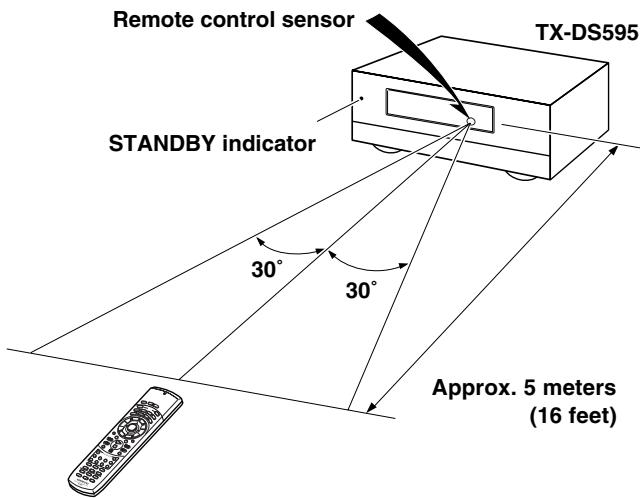
Using the remote controller
Point the remote controller toward the remote control sensor. The STANDBY indicator lights up when the unit receives a signal from the remote controller.
Notes:
- Place the unit away from strong light such as direct sunlight or inverted fluorescent light which can prevent proper operation of the remote controller.
- Using another remote controller of the same type in the same room or using the unit near equipment which uses infrared rays may cause operational interference.
- Do not put objects on the remote controller. Its buttons may be pressed by mistake and drain the batteries.
- Make sure the audio rack doors do not have colored glass. Placing the unit behind such doors may prevent proper remote controller operation.
- If there is any obstacle between the remote controller and the remote control sensor, the remote controller will not operate.
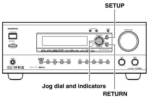
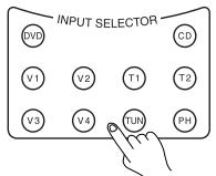
Here is an explanation of the controls and displays on the front panel of the TX-DS595.
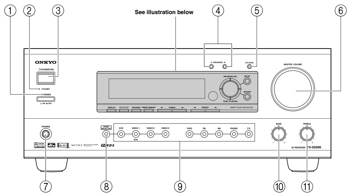
Front panel
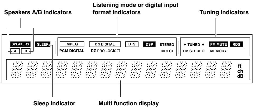
Front panel display
For operational instructions, see page indicated in brackets [ ].
① POWER switch [16]
Turns on and off the main power supply for the TX-DS595.
2 STANDBY indicator [16]
Lights when the TX-DS595 is in the standby state and flashes when a signal is received from the remote controller.
③ STANDBY/ON button [16]
Press to turn on the TX-DS595 when in the standby state. Press again to return the TX-DS595 to the standby state.
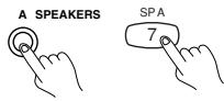
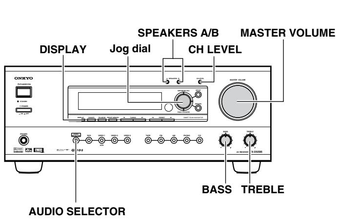
4 SPEAKERS A/B buttons [25, 26]
Press these buttons to turn on and off speakers systems A and B.
CH LEVEL button [27]
Press to select the channel whose level is to be adjusted.
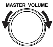
6 MASTER VOLUME dial [25]
The MASTER VOLUME dial is used to control the volume.
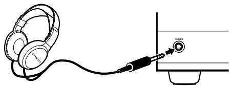
7 PHONES jack
To listen with headphones, plug a pair headphones with a standard stereo plug into the PHONES jack on the TX-DS595 front panel.
When you connect headphones, the unit will enter STEREO mode automatically and no sound will be heard from the speakers. If you have selected MULTI CH INPUT, you will hear sound only from the FRONT L and R channels. Note that the volume level for the headphones is adjustable.
8 AUDIO SELECTOR button [27]
This button is used to select the type of audio input signal. Each time pressed, the setting cycles from "AUTO" "MULTICH" "ANALOG" and back.
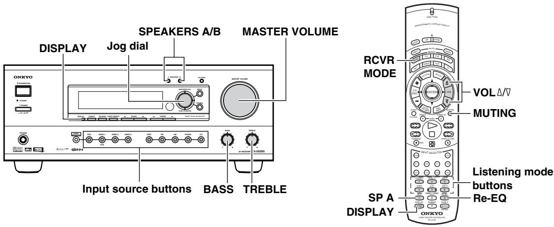
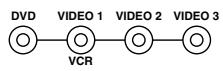
9 Input source buttons (DVD,VIDEO 1-3, TAPE, FM, AM, PHONO, and CD) [25]
These buttons are used to select the input source.
10 BASS dial [26]
Boosts or cuts the bass response. Bass adjustment is effective only for the front speakers and headphones.
11 TREBLE dial [26]
Boosts or cuts the treble response. Treble adjustment is effective only for the front speakers and headphones.
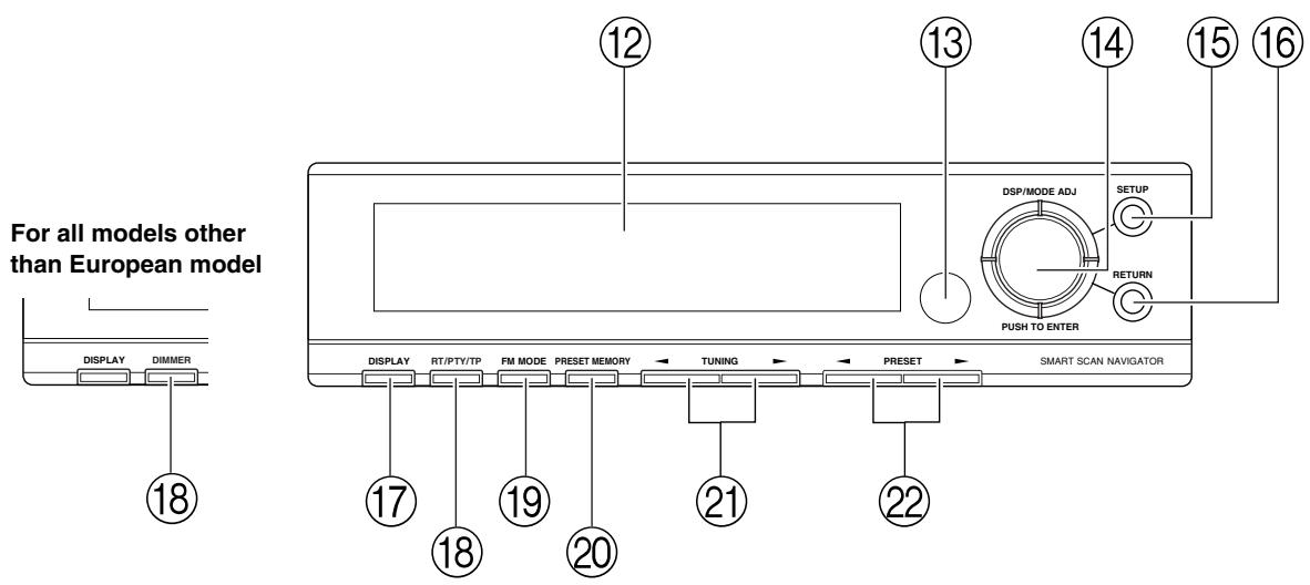
12 Front display
Remote control sensor [5]
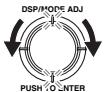
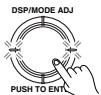
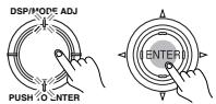
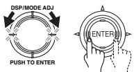
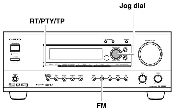
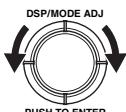
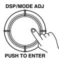
SMART SCAN NAVIGATOR jog dial and indicators [19, 20, 22, 24-27, 30-32]
Used to make settings in the setup display, change listening mode settings, and more.
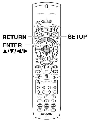
15 SETUP button [19, 20, 30-32]
Press to enter and exit the setup mode.
16 RETURN button [19, 20, 30-32]
Press to move up one level in the setup mode.
17 DISPLAY button [26]
The DISPLAY button is used to display information about the current input source signal. Each time you press the display button, the screen changes to show you different information concerning the input signal.
18 RT/PTY/TP (European models only) button [24]
This button is only available on European models. Use this button to help tune into the Radio Data System (RDS) for FM broadcasting. RDS was developed within the European Broadcasting Union (EBU) and is available in most European countries. Each time the button is pressed, the display changes from RT (radio text) to PTY (program type) to TP (traffic program) and then back to RT again.
DIMMER (other than European models) button
Press to set the brightness of the front display. There are 3 settings available: normal, dark, and very dark.
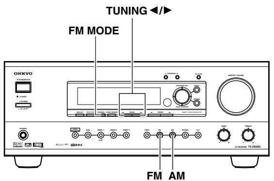
19 FM MODE button [21]
When there is too much noise in the stereo reception of an FM broadcast, press to turn off the FM MUTE function.
20 PRESET MEMORY button [22]
This button is used to assign the radio station that is currently tuned in to a preset channel or delete a previously preset station.
21 TUNING / buttons [21]
Use these buttons to change the tuner frequency. The tuner frequency is displayed in the front display and it can be changed in 50kHz increments for FM and 10kHz (or 9kHz ) increments for AM.
When FM is selected, you can hold down one of the tuning buttons and then release it to activate the auto-search feature. It will search for a station in the direction of the button you pressed and stop when it tunes into one.
22 PRESET / buttons [22]
When AM or FM is selected as the input source, press one of these buttons to jump to a radio station that you preset using the PRESET MEMORY button. Pressing the right button moves from the most recently preset station to older ones, and pressing the left button moves in the reverse order.
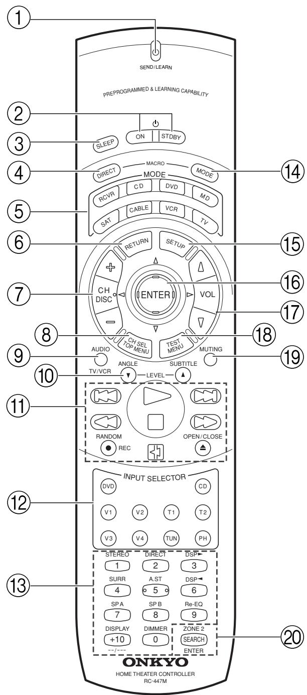
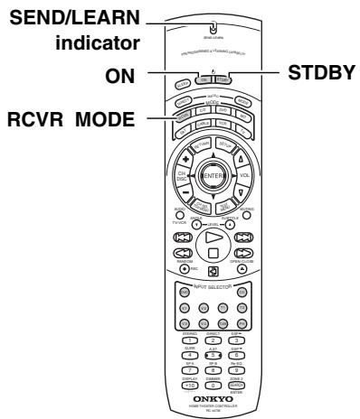
① SEND/LEARN indicator
This indicator acts as a guide when commands are programmed into or sent by the remote controller. It also warns the user when an error is made or battery power is low.
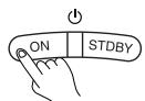
2 ON/STDBY button [16]
ON: Turns on the TX-DS595.
STDBY: Places the TX-DS595 in the standby state.
Be aware that pressing the STDBY button only places the TX-DS595 in standby and does not turn the power completely off.
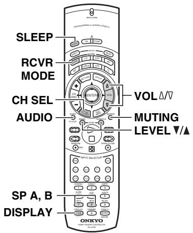
③ SLEEP button [26]
Sets the sleep function.
The SLEEP button enables you to set the TX-DS595 to turn off automatically after a specified time period.
④ DIRECT MACRO button [46]
For executing and programming the Direct Macro function.
MODE buttons and indicators [40-47]
For selecting the component to be operated by the remote controller. When a MODE button is pressed, it will light green for 8 seconds. The selected MODE button will also light whenever any other operation button is pressed to tell you which mode the remote controller is in.
⑥ RETURN button [19, 20, 30-32]
Press to move up one level in the setup mode.
CH/DISC +/- button [35, 36]
When in the RCVR mode, for selecting a tuner preset channel. For selecting the disc to be played back for components with disc changers when in the DVD or CD modes.
CH SEL/TOP MENU button [36]
CH SEL: For selecting the speaker for level adjustment when in the RCVR mode. Used together with the LEVEL / buttons.
TOP MENU: When in the DVD mode, for displaying the menu screen(s) recorded on DVD media.
9 AUDIO/TV/VCR button [27, 41]
AUDIO: For selecting the audio input signal. The setting changes from "AUTO" to "MULTICH" to "ANALOG" and back each time this button is pressed.
TV/VCR: Must be preprogrammed for use in the TV and VCR modes.
LEVEL / ANGLE and LEVEL A/SUBTITLE buttons
LEVEL / : Select the speaker whose volume is to be adjusted using the CH SEL button and adjust the volume using the LEVEL / buttons in the RCVR mode. [9, 27]
ANGLE: When in the DVD mode, for selecting a camera angle when a DVD-Video is recorded with multiple angle playback. [36]
SUBTITLE: When in the DVD mode, for selecting one of the subtitle languages recorded on a DVD-Video. [36]
11 CD/TAPE/DVD/MD operation buttons [34-37]
For operating Onkyo components connected to the TX-DS595.
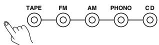
12 INPUT SELECTOR buttons [25]
Selects an input source.
Same as the input selector buttons on front panel of the TX-DS595. The input source for each buttons is given here. DVD:DVD, CD:CD, V1:VIDEO1, V2:VIDEO2, V3:VIDEO3, V4:Not used with the TX-DS595, T1:TAPE, T2:Not used with the TX-DS595, TUN:FM/AM, PH:PHONO.
![ONKYO TX-DS595 - INPUT SELECTOR buttons [25] - 1](/content/2025/01/151679/images/85b9fb395bdc1d9fb285d9461107a1a8fd60904e7eb96545ec9497e785e1a70c.jpg)
Numeric key/Listening mode selector/SP A, B/ Re-EQ/DISPLAY/DIMMER buttons
1 to 9, +10, --/---, 0: For entering the number of a track.
STEREO, DIRECT, DSP , SURR, A.ST: You can select a listening mode. [25, 28]
STEREO: Changes the listening mode directly to the Stereo listening mode. If pressed, the listening mode for the selected input source set in the Listening Mode Preset is also changed to the Stereo listening mode.
SURR (Surround): Changes the listening mode to the surround mode for the current input signal (e.g., Dolby Pro Logic II, Dolby Digital, or DTS). If pressed, the listening mode for the selected input source set in the Listening Mode Preset is also changed to the Surround listening mode.
For Dolby Pro Logic II, this button also changes the mode between Dolby Pro Logic II Movie and Dolby Pro Logic II Music.
DIRECT: Changes the listening mode directly to the Direct listening mode. If pressed, the listening mode for the selected input source set in the Listening Mode Preset is also changed to the Direct listening mode.
A.ST (All Channel Stereo): Changes the listening mode directly to the Stereo listening mode. If pressed, the listening mode for the selected input source set in the Listening Mode Preset is also changed to the All Channel Stereo listening mode.
DSP : Changes the listening mode as shown below.
Direct Stereo Surround Orchestra Unplugged Studio-Mix TV Logic All Ch Stereo Direct.
If pressed, the listening mode for the selected input source set in the Listening Mode Preset is also changed.
Re-EQ: Depending on the listening mode, you can turn the cinema re-equalization function on or off. [25]
Re-EQ (re-equalization) takes the edginess or "brightness" out of your home cinema sound to compensate for the fact that sound mixed for theaters may sound too bright when played back through speakers in the home environment.
On: Select to turn on the re-equalization filter.
Off: Select to turn off the re-equalization filter.
Note:
The Re-EQ function is effective on the Dolby Pro Logic II Surround and Dolby Digital Surround.
SP A, SP B: For turning on and off speakers systems A and B. [26]
DISPLAY: For changing the display in the front display. [26]
DIMMER: Adjusts the display brightness.
There are three settings available: normal, dark and very dark.

MODE MACRO button [45]
For executing and programming the Macro function.
![ONKYO TX-DS595 - MODE MACRO button [45] - 1](/content/2025/01/151679/images/2fa8bed17e54f70de70bb9d2f79f2dd7273d0bd2f8724141fc777dc9fe91edce.jpg)
SETUP button [19, 20, 30-32]
Press to enter and exit the setup mode.
![ONKYO TX-DS595 - SETUP button [19, 20, 30-32] - 1](/content/2025/01/151679/images/7c2e0c728aa9890899d01820d77b2ee164b6945783ab89b63306b8dbcd8e4312.jpg)
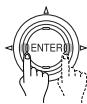
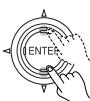
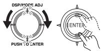
ENTER/cursor button [19, 20, 30-32]
For selecting and entering settings in the setup mode.
![ONKYO TX-DS595 - ENTER/cursor button [19, 20, 30-32] - 1](/content/2025/01/151679/images/c95e7bba15d41497b60ad7d0504799aa3659462d5970efcdef07c15b0afc2bdb.jpg)
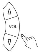
VOL button
For adjusting the volume.

TEST/MENU button
TEST: Outputs a test tone for setting speaker levels.
Use this button in conjunction with the LEVEL / and CH SEL buttons to calibrate the speakers levels.
- Press the TEST button.
A test sound (pink noise) will be heard from the left front speaker. At this point, it is not necessary to adjust the volume of the test sound.
- Press the CH SEL button.
The test sound will now be heard from a different speaker.
- Use the LEVEL / buttons to adjust the volume of the test sound from this speaker to the same level that you heard from the previous speaker.
- Repeat the procedure in step 2 and 3 until the volume of the test sound from all speakers is the same level.
Each time you press the CH SEL button, the test sound will be heard from a different speaker. The speaker order for calibration is front left center front right surround right surround left subwoofer.
- Press the TEST button to exit the setting.
For a more detailed explanation of how to calibrate the speaker levels, see page 20.
MENU: When in the DVD mode, this button displays the DVD menu.

MUTING button [26]
Activates the mute function.
![ONKYO TX-DS595 - MUTING button [26] - 1](/content/2025/01/151679/images/53d74a05dba6bcb16718f453268374e06e8a7958e857bff01c9a9cc15b56b552.jpg)
ZONE 2/SEARCH/ENTER button
ZONE 2: Not used with the TX-DS595.
SEARCH: When in the DVD mode, for finding the specific section on a disc where you want to start playback.
ENTER: When in the MD mode, for confirming the selection.
Here is explanation of how to connect the main components to the TX-DS595 in the standard manner. There are many ways that any one component can be connected, and it is up to you to decide which method best fits your situation. The directions given here are only one option and should only be thought of as such. It is best to fully understand the nature of each connector and terminal as well as each of your components and their features to ascertain which method of connection is best.
- Be sure to always refer to the instructions that came with the component that you are connecting.
- Do not plug in the power cord until all connections have been made.
- For input jacks, red connectors (marked R) are used for the right channel, white connectors (marked L) are used for the left channel, and yellow connectors (marked V) are used for video connection.
- Do not bind audio/video connection cables with power cords and speaker cables. Doing so may adversely affect the picture and sound quality.
-
When using the digital inputs, make sure to also connect the analog connections whenever possible.
-
Insert all plugs and connectors securely. Improper connections can result in noise, poor performance, or damage to the equipment.
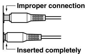
- When using one of the optical input jacks, remove the protective cap and keep it safely. When the jack is not used, replace the protective cap.
- When using an optical input jack, always use an optical fiber cable.
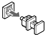
Optical digital input terminal
An optical digital input terminal is equipped with a protection cap. When connecting, remove this cap. When not using, put the cap back on the terminal.
Connecting your audio components [11]
For worldwide models only
Default setting
| Input source | Digital input | Multichannel |
| DVD | COAX 1 | Yes |
| VIDEO 1 | COAX 2 | No |
| VIDEO 2 | ---- | No |
| VIDEO 3 | OPT 2 | No |
| VIDEO 4 | ---- | No |
| TAPE | ---- | No |
| FM | ||
| AM | ||
| PHONO | ---- | No |
| CD | OPT 1 | No |
COAX: Coaxial OPT: Optical ----: No setting : Not applicable
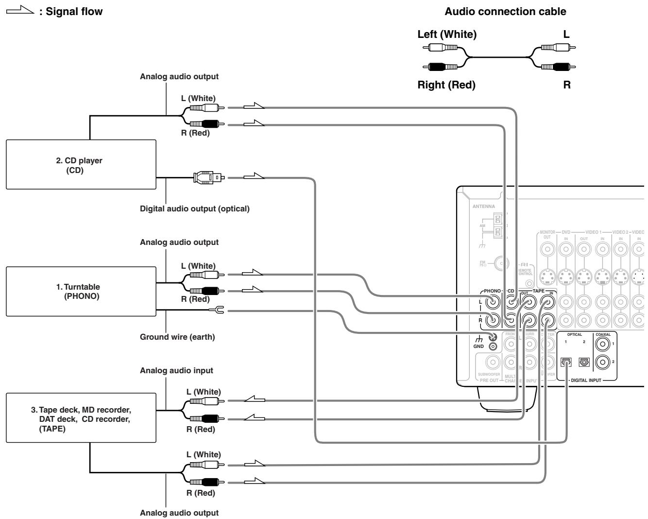
Connecting your audio components
Below is an example of how you can connect your audio components to the TX-DS595. Refer to the diagram above for the following connection examples.
1. Connecting a turntable (PHONO)
Using an RCA-type audio connection cable, connect the output terminal on the turntable to the PHONO input jacks on the TX-DS595. Make sure that you properly connect the left channel to the L jack and the right channel to the R jack.
Note:
The TX-DS595 is designed for use with moving magnet cartridges. For proper operation, connect a ground (or earth) wire to the GND terminal. For some turntables, however, connecting the ground wire may cause increased noise, and in such a case, a ground wire is not necessary and should not be connected.
2. Connecting a compact disc player (CD)
Using an RCA-type audio connection cable, connect the output terminal on the compact disc player to the CD input jacks on the TX-DS595. Make sure that you properly connect the left channel to the L jack and the right channel to the R jack.
If the compact disc player has a digital output jack as well, be sure to also connect it to either a DIGITAL INPUT (COAXIAL) or DIGITAL INPUT (OPTICAL) jack on the TX-DS595 depending on the type of connector on the compact disc player.
With the initial settings of the TX-DS595, the CD input source is set for digital input at the OPTICAL 1 jack.
If the digital connection is made at a different jack, this must be changed at the setup menu: Input Setup Audio Setup Digital Input (see page 29).
3. Connecting a cassette tape deck, MD recorder, DAT deck, or CD recorder (TAPE)
Using an RCA-type audio connection cable, connect the output terminals (PLAY) of the device to the TAPE IN jacks on the TX-DS595 and the input terminals (REC) to the TAPE OUT jacks. Make sure that you properly connect the left channel to the L jack and the right channel to the R jack.
If the device has a digital output jack as well, be sure to also connect it to either a DIGITAL INPUT (COAXIAL) or DIGITAL INPUT (OPTICAL) jack on the TX-DS595 depending on the type of connector on the device.
With the initial settings of the TX-DS595, the TAPE input source is set for no digital input.
If you connect the device to the DIGITAL INPUT terminal, then this input source must be set for digital input at the setup menu: Input Setup Audio Setup Digital Input (see page 29).
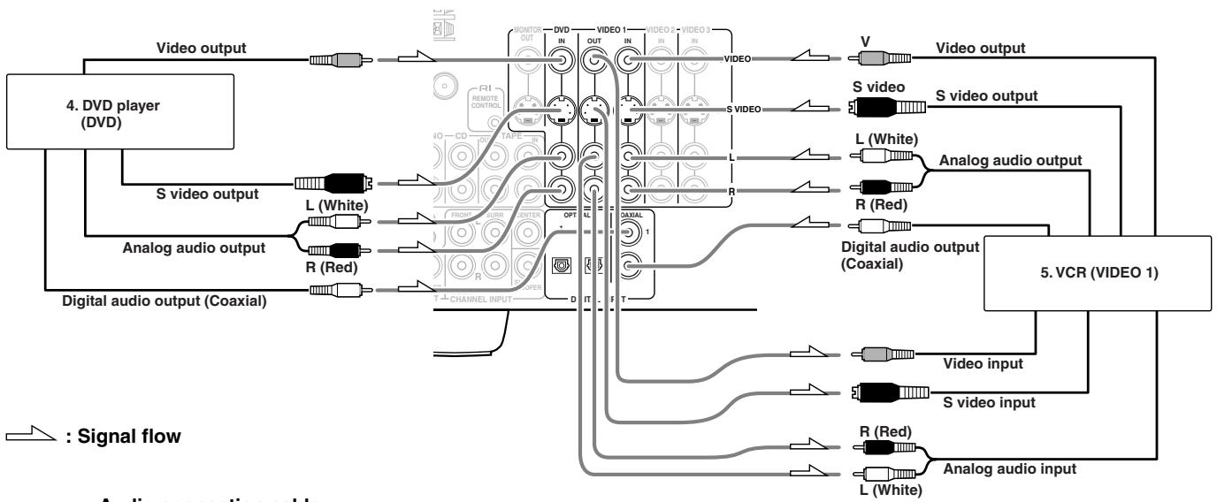

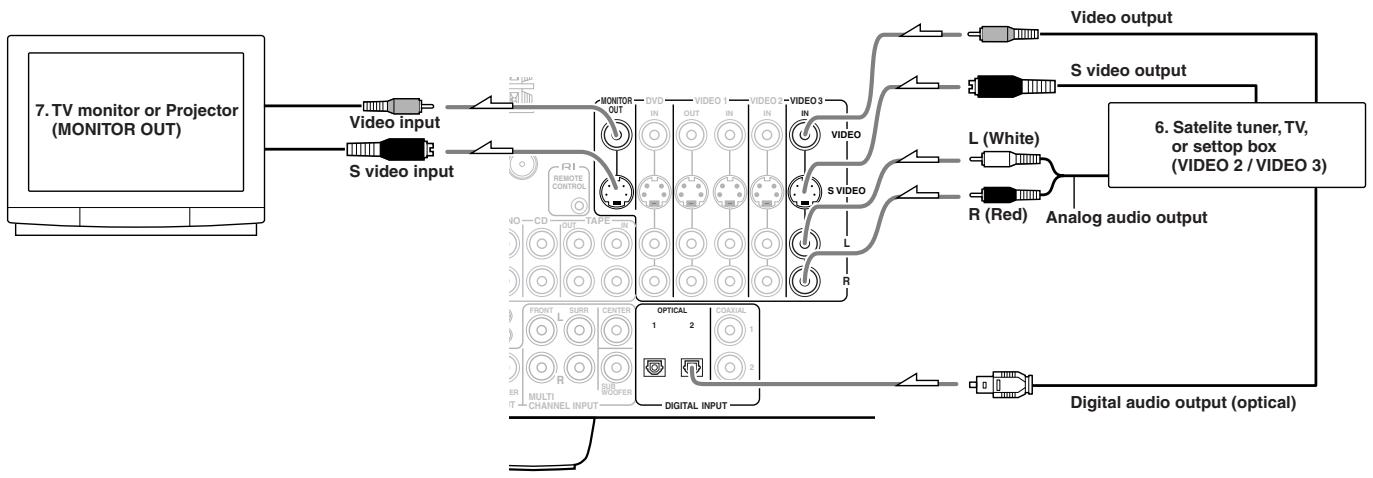
Connecting your video components
Below is an example of how you can connect your video components to the TX-DS595. Refer to the diagram above for the following connection examples.
The flow of the video signals is as follows:
- The signal that comes in from VIDEO IN is sent toVIDEO OUT.
- The signal that comes in from SVIDEO IN is sent to SVIDEO OUT
4. Connecting a DVD player (DVD)
If the device is equipped with an S video output terminal, connect it to the DVD S VIDEO IN terminal with an S video cable. If it does not have an S video output terminal, connect its video output terminal to the DVD VIDEO IN terminal using an RCA-type video connection cable. You do not need to connect to both the DVD SVIDEO IN and DVDVIDEO IN terminals.
Using an RCA-type audio connection cable, connect the audio output terminal on the device to the audio DVD IN jacks on the TX-DS595. Make sure that you properly connect the left channel to the L jack and the right channel to the R jack.
If the device has a digital output jack as well, be sure to also connect it to either a DIGITAL INPUT (COAXIAL) or DIGITAL INPUT (OPTICAL) jack on the TX-DS595 depending on the type of connector on the DVD player.
With the initial settings of the TX-DS595, the DVD input source is set for digital input at the COAXIAL 1 jack.
If the digital connection is made at a different jack, this must be changed at the setup menu: Input Setup Audio Setup Digital Input (see page 29).
5. Connecting a video cassette recorder (VIDEO 1)
If the video cassette recorder is equipped with an S video output terminal, connect it to the SVIDEO 1 IN terminal with an S video cable. If it does not have an S video output terminal, connect its video output terminal to theVIDEO 1 IN terminal using an RCA-type video connection cable. You do not need to connect to both the SVIDEO 1 IN andVIDEO 1 IN terminals.
Using an RCA-type audio connection cable, connect the audio output terminal on the video cassette recorder to the same Video 1 IN audio jacks on the TX-DS595 and audio input terminal to the Video 1 OUT audio jacks. Make sure that you properly connect the left channel to the L jack and the right channel to the R jack.
If the device has a digital output jack as well, be sure to also connect it to either a DIGITAL INPUT (COAXIAL) or DIGITAL INPUT (OPTICAL) jack on the TX-DS595 depending on the type of connector on the device.
With the initial settings of the TX-DS595, the VIDEO 1 input source is set for digital input at the COAXIAL 2 jack.
If the digital connection is made at a different jack, this must be changed at the setup menu: Input Setup Audio Setup Digital Input (see page 29).
6. Connecting a satellite tuner, television, or settop box (VIDEO 2/3)
If the device is equipped with an S video output terminal, connect it to the SVIDEO 3 IN terminal with an S video cable. If it does not have an S video output terminal, connect its video output terminal to theVIDEO 3 IN terminal using an RCA-type video connection cable. You do not need to connect to both the SVIDEO 3 IN andVIDEO 3 IN terminals.
Using an RCA-type audio connection cable, connect the audio output terminal on the satellite tuner or television to the same Video 3 IN audio jack on the TX-DS595. Make sure that you properly connect the left channel to the L jack and the right channel to the R jack.
If the device have a digital output jack as well, be sure to also connect it to either a DIGITAL INPUT (COAXIAL) or DIGITAL INPUT (OPTICAL) jack on the TX-DS595 depending on the type of connector on the device.
With the initial settings of the TX-DS595, the VIDEO 3 input source is set for digital input at the OPTICAL 2 jack.
If the digital connection is made at a jack different from the initial settings, this must be changed at the setup menu: Input Setup Audio Setup Digital Input (see page 29).
You can also connect the device to the VIDEO 2 IN input jacks on the TX-DS595 just like you can to the VIDEO 3 IN input jacks.
With the initial settings of the TX-DS595, the VIDEO 2 input source is set for no digital input.
If you connect the device to the DIGITAL Input terminal, then this input source must be set for digital input at the setup menu: Input Setup Audio Setup Digital Input (see page 29).
7. Connecting a television monitor or projector (MONITOR OUT)
If the monitor or projector is equipped with an S video output terminal, connect it to the MONITOR OUT S VIDEO terminal with an S video cable. If it does not have an S video output terminal, connect its video output terminal to the MONITOR OUT VIDEO terminal using an RCA-type video connection cable. You do not need to connect to both the MONITOR OUT SVIDEO and MONITOR OUT VIDEO terminals.
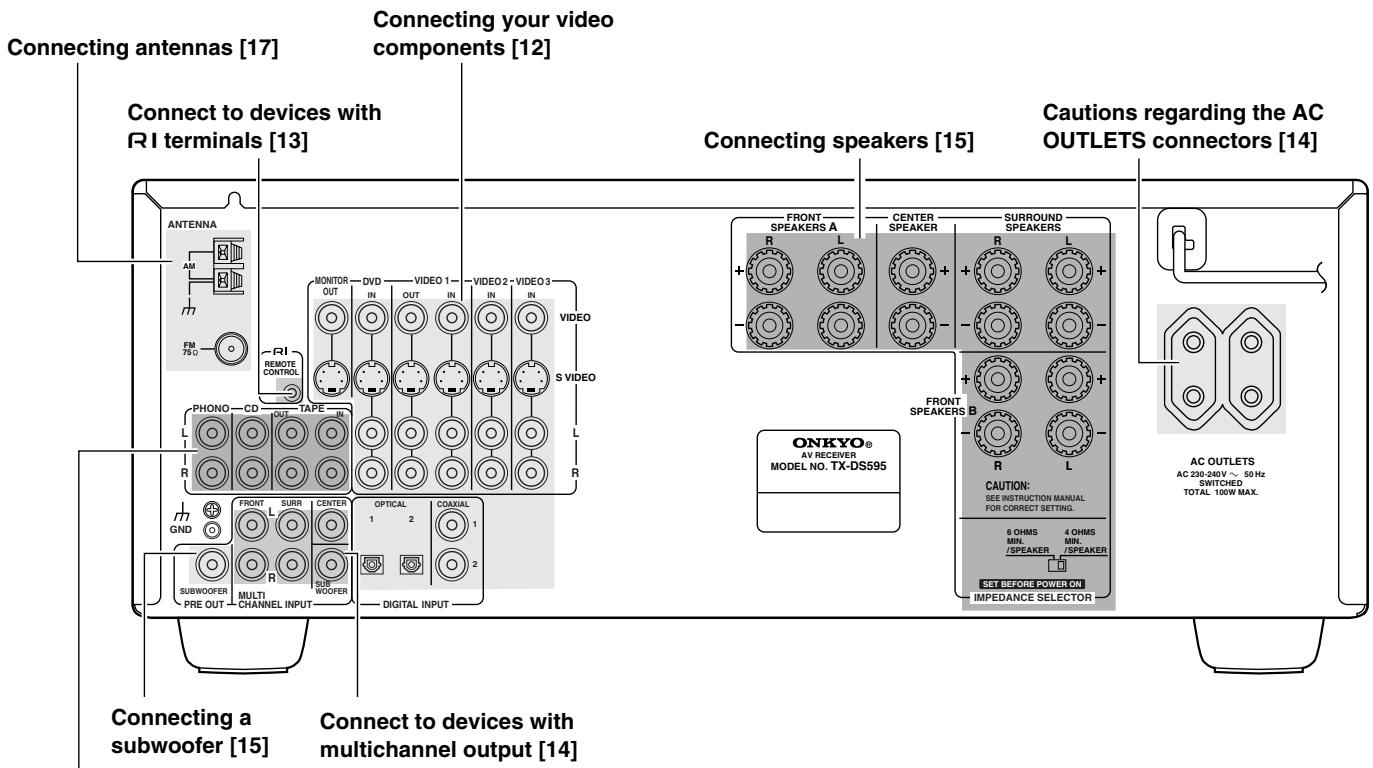
Connect to devices with R terminals
The RI terminal on the TX-DS595 is for connecting other Onkyo components equipped with the same RI terminal. When a component are RI-connected, you can point the remote controller supplied with the TX-DS595 at the sensor on the TX-DS595 and operate that component without having to switch remote controllers. In addition, by connecting components to the RI terminal, you can also perform the system operations given below.
Power on/ready function
When the TX-DS595 is in the standby state, if an RI-connected component is turned on, then the TX-DS595 also turns on and the input source selected at the TX-DS595 automatically switches to that component.
If the power cord for an RI-connected component is connected to the AC OUTLET on the TX-DS595, or if the TX-DS595 is turned on, this function will not work.
Direct change function
When the play button is pressed at an RI-connected component, the input source selected at the TX-DS595 automatically changes to that component.
Power off function
When the TX-DS595 is placed in the standby state, all RI-connected components are also automatically put into the standby state.
CAUTION
If an MD recorder is connected to the TAPE jack on the TX-DS595, switch the Input Selector from TAPE to MD (see page 16).
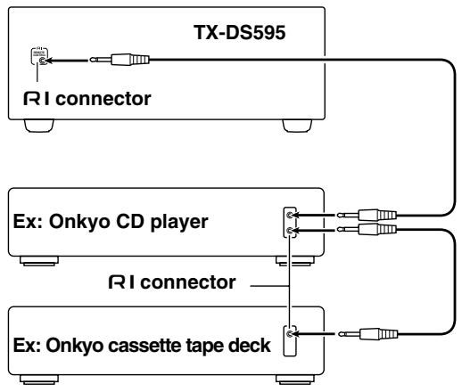
To connect components using the RI terminal, simply connect a remote control cable from this RI terminal to the RI terminal of the other component. An RI remote control cable with a 1/8-inch (3.5-mm) miniature two-conductor plug comes with every cassette tape deck, compact disc player, MD recorder, and DVD player that has an RI terminal.
- For remote control operation, the audio connection cables must also be connected.
- The RC-447M remote controller does not support turntables.
- If a component has two RI terminals, you can use either one to connect to the TX-DS595. The other one can be used to daisy chain with another component.
- With Onkyo DVD players, you can enter the pre-program code so that you can operate the DVD player directly with the remote controller without connecting the RI terminals (see page 38).
Connect to devices with multichannel output
By connecting a DVD player, MPEG decoder, or other component that has a multi channel port, you can playback the audio with 5.1 channel output. So, be sure to prepare a cable that can properly connect the TX-DS595 to the peripheral device.
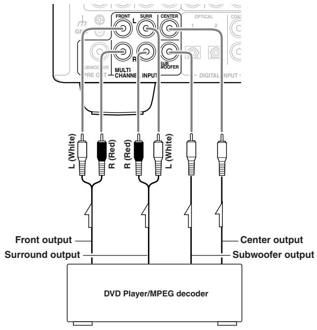
TX-DS595 MULTI CHANNEL INPUT
Cautions regarding the AC OUTLETS connectors
The TX-DS595 is supplied with AC mains outlets for connecting the power cords from other devices so that their power is supplied through the TX-DS595. By doing this, you can use the STANDBY/ON button on the TX-DS595 to turn on and off the connected devices as well.
The shape, number, and total capacity of the AC outlets may differ depending on the area of purchase.
Caution:
Make sure that the total capacity of the other components connected to this unit does not exceed the capacity that is printed on the rear panel (e.g., 120 watts).
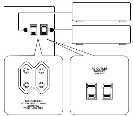
ex. European and some Asian models
ex. USA and Canadian models
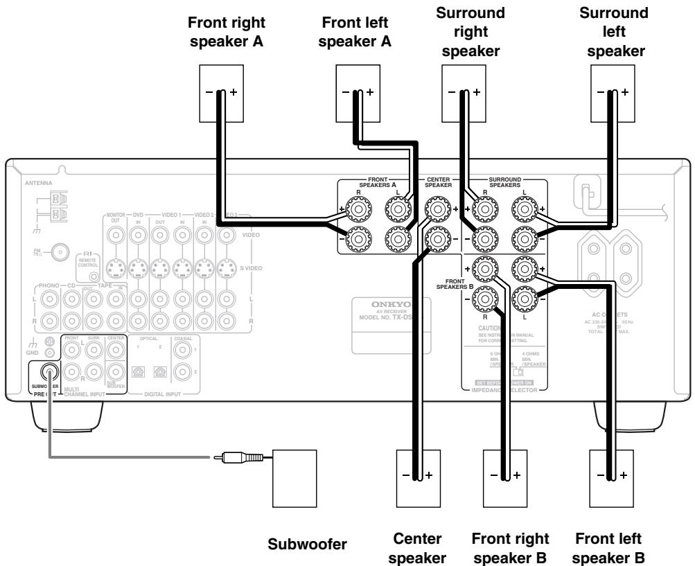
Connecting speakers
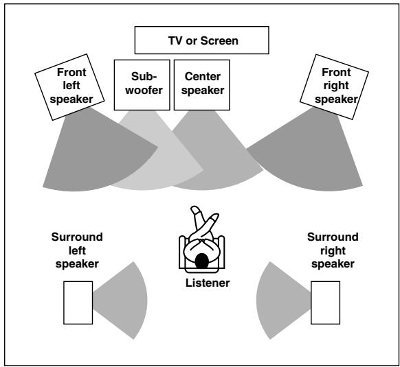
Positioning speakers
Speaker placement plays an important role in the reproduction of Surround sound. The placement of the speakers varies depending on the size of the room and the wall coverings used in the room. The illustration shows an example of a layout for standard speaker placement. Refer to this example when you position the speakers in order to experience the best of Surround sound.
Standard speaker placement
For ideal Surround effects, all speakers should be installed. If a center speaker or subwoofer is not connected, the sound from the unused channel is properly distributed to the connected speakers in order to produce the best Surround sound possible.
Front: The left, right, and center speakers should face the seated listener and be placed at ear level. The center speaker produces a richer sound image by enhancing the perception of the sound's source and movement.
Surround: Place the left and right Surround speakers 3 feet (1 meter) above the listener's ear level and facing toward the sides of the room, making sure that the listener is within the speakers' dispersion angle. These speakers produce the feel of a moving sound while creating the sensation of being in the middle of the action.
Subwoofer: Install a subwoofer with a built-in power amplifier for powerful bass sounds. The placement of the subwoofer does not affect the final quality of the sound image too much, so you can install it with the room layout in mind.
Refer to the speaker's instruction manual for more details.
Connecting speakers
1. Check the impedance of the speakers you are connecting.
The TX-DS595 requires speakers with an impedance of 4 or greater. Connecting speakers with an impedance of less than 4 may damage the TX-DS595.
2. Set the IMPEDANCE SELECTOR switch according to the impedance of the speakers being connected.
If all speakers have an impedance of 6 or greater, slide the IMPEDANCE SELECTOR switch to the left (6 OHMS MIN./SPEAKER). If one or more speakers have an impedance of less than 6 , slide the IMPEDANCE SELECTOR switch to the right (4 OHMS MIN./SPEAKER).
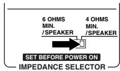
4 Ω or above/speaker
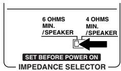
6 Ω or above/speaker
Notes:
- The power to the TX-DS595 must not be turned on when changing the IMPEDANCE SELECTOR setting.
-
When you are using only one speaker or when you wish to listen to monaural (mono) sound, a single speaker should never be connected in parallel to both the right and left-channel terminals simultaneously.
-
To prevent damage to circuitry, never short-circuit the positive (+) and negative (-) speaker wire.
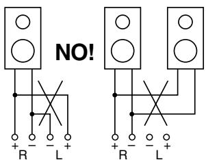

- Be sure to connect the positive and negative cables for the speakers properly. If they are mixed up, the left and right signals will be reversed and the audio will sound unnatural.
- Do not connect more than one speaker cable to one speaker terminal. Doing so may damage the TX-DS595.
- Use FRONT SPEAKERS B terminals to connect a second pair of front speakers.
- When you listen to surround audio or select Multichannel, be sure to turn on SPEAKERS A.
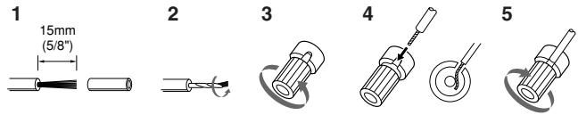
Connecting the speaker cable
1. Strip away 5/8 inch (15 mm) of wire insulation.
2. Twist wire ends very tight.
3. Unscrew
4. Insert wire
5. Screw
Connecting a subwoofer
Use the PRE OUT SUBWOOFER jack to connect a subwoofer with a built-in power amplifier. If your subwoofer does not have a built-in amplifier, connect an amplifier to the PRE OUT SUBWOOFER jack and the subwoofer to the amplifier.
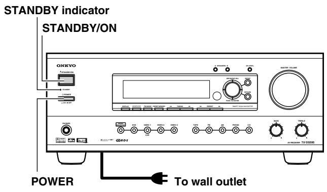
- The TX-DS595 is shipped with the main power (POWER) switch in the on position (ON). When the power cord is plugged in for the first time, the TX-DS595 will automatically enter the standby state and the STANDBY indicator will light (same condition after step 2 below).
- Before you plug in the TX-DS595, confirm that all connections have been made properly.
- Turning on the power may cause a momentary power surge, which might interfere with other electrical equipment on the same circuit, such as computers. If this happens, use a wall outlet on a different circuit.
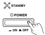
1. Plug the power cord into an AC wall outlet.
2. Press the POWER switch to set the TX-DS595 to standby state.
The STANDBY indicator will light up.
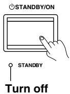
3. Press the STANDBY/ON button to turn on the TX-DS595. The display and four jog dial indicators will light up and the STANDBY indicator will turn off.
If you press the STANDBY/ON button again, the receiver returns to Standby mode.
Turning the power on from the remote controller:
Before you can use the remote controller, you must perform steps 1 and 2 above and place the TX-DS595 in the standby state.
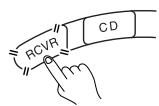
1. Press the RCVR MODE button.
The RCVR MODE button lights green.
2. Press the ON button to turn on the TX-DS595 (take it out of the standby state).
To return the TX-DS595 to the standby state, press the STDBY button.
To change the display of the input source from TAPE to MD:
If you connected an MD recorder to the TAPE jack on the TX-DS595, you can have "MD" appear when the TAPE source button is pressed. By changing the display, if an Onkyo MD recorder RI-connected, the RI system functions will become enabled.
Changing the display:
Press and hold down the TAPE source button until the display changes from TAPE to MD (approx. 3 seconds).
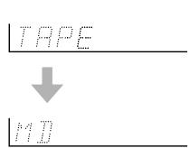

To return the display to its original setting, perform the same procedure. This setting is necessary to allow R1 system functions for the connected cassette tape or MD recorder.
Memory preservation
This unit does not require memory preservation batteries. A built-in memory power backup system preserves the contents of the memory during power failures and even when the POWER switch is set to off. The POWER switch must be set to on in order to charge the backup system.
The memory preservation period after the unit has been turned off varies depending on climate and placement of the unit. On the average, memory contents are protected over a period of a few weeks after the last time the unit has been turned off. This period is shorter when the unit is exposed to a highly humid climate.
To use the tuner of TX-DS595, it is necessary to prepare the supplied FM and AM antennas.
- Adjustment and placement of the FM and AM antennas for better reception must be done while listening to a station broadcast.
- If better reception cannot be obtained, then placement of an outside antenna is recommended.
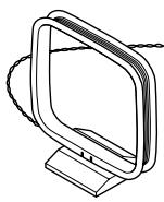
Assembling the AM loop antenna
Assemble the loop antenna as shown in the illustration.
- Refer to "Connecting the AM loop antenna" below for details on connecting the loop antenna.
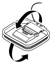
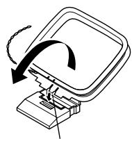
Insert into the hole.
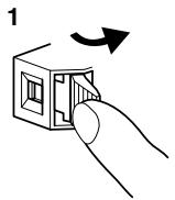
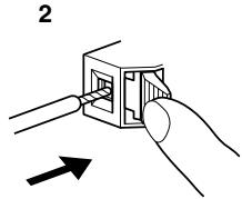
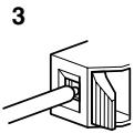
Connecting the AM antenna cable
- Press down the lever.
- Insert the wire into the hole.
- Release the lever.
Connecting the included antennas
Connecting the FM indoor antenna:
The FM indoor antenna is for indoor use only. During use, extend the antenna and move it in various directions until the clearest signal is received. Fix it with push pins or similar implements in the position that will cause the least amount of distortion.
If the reception is not very clear with the attached FM indoor antenna, the use of an outdoor antenna is recommended.
Connecting the AM loop antenna:
The AM loop antenna is for indoor use only. Set it in the direction and position where you receive the clearest sound. Put it as far away as possible from the TX-DS595, televisions, speaker cables, and power cords.
When reception is not satisfactory with the attached AM loop antenna alone, connection of an outdoor antenna is recommended.
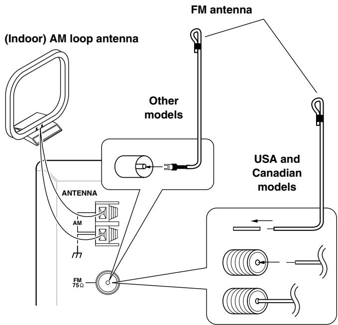
Strip away the insulation from the end of the cable, then fully insert the stripped end of the cable.
Hint:
Either of the split ends of the AM antenna can be connected to either terminal. Unlike speaker cabling, there is no polarity for AM broadcast signals.
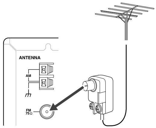
Connecting an FM outdoor antenna
Please make sure that you follow the considerations:
- Keep the antenna away from noise sources (neon signs, busy roads, etc.).
- It is dangerous to put the antenna close to power lines. Keep it well away from power lines, transformers, etc.
- To avoid the risk of lightning and electrical shock, grounding is necessary. Follow item 14 of the "Important Safeguards" on page 2 when you install the outdoor antenna.
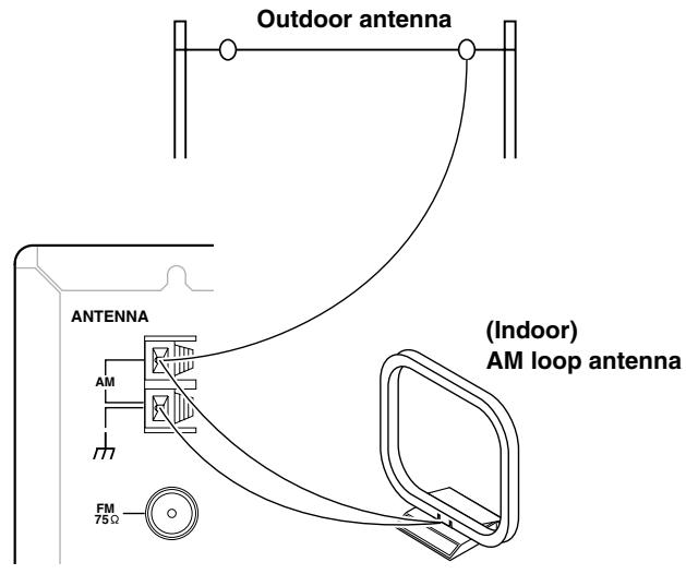
Connecting an AM outdoor antenna
An outdoor antenna will be more effective if it is stretched horizontally above a window or outside.
- Do not remove the AM loop antenna.
- To avoid the risk of lightning and electrical shock, grounding is necessary. Follow item 14 of the "Important Safeguards" on page 2 when you install the outdoor antenna.
Note:
If you are using the TX-DS595 worldwide model in a region where AM frequencies are delineated by 10-kHz steps, be sure to set the AM Freq Step Setup setting accordingly (see page 32).
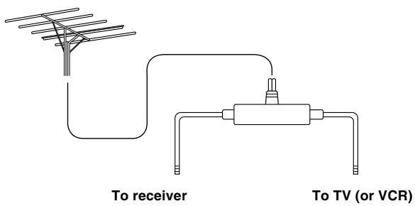
Directional linkage
Do not use the same antenna for both FM and TV (or VCR) reception since the FM and TV (or VCR) signals can interfere with each other. If you must use a common FM/TV (or VCR) antenna, use a directional linkage type splitter.
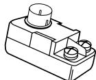
Connecting the antenna cable to the 75/300 Ω antenna adapter (For all models other than USA, Canadian and European models)
Connecting the 300 ribbon wire:
Loosen the screws and wrap the wire around these screws. Then tighten the screws with a screwdriver.
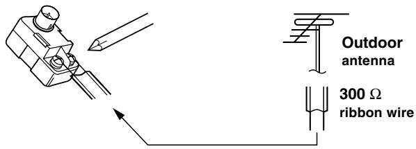
Connecting the coaxial cable:
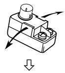
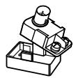
- With your fingernail, or a small screwdriver, press the stoppers of the 75/300 Ω antenna adapter outward and remove the cover.
- Remove the transformer wire A from slit B and insert it into slit C.
- Prepare the coaxial cable as shown in the diagram.
-
Connect the 75/300 Ω antenna adapter to the coaxial cable.
-
Insert the end of the cable.
- Clamp it in place with pliers.
5. Reinstall the cover.
1
2
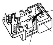
Wire A
Slit C
Slit B
3,4
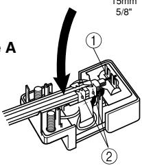
15mm 5/8"
Follow the steps below before you start operating the unit.
Speaker Configuration
These settings tell the TX-DS595 which speakers you have connected and what size they are.
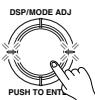
1. Press the SETUP button.
TX-DS595
Remote
controller


If anything other than "1. SPEAKER SETUP" appears, turn the jog dial or press the and cursor buttons on the remote controller until "1. SPEAKER SETUP" appears.


I . SPEAKER - SETUP
The display changes as follows: "1. SPEAKER SETUP" "2. INPUT SETUP" "3. PREFERENCE."
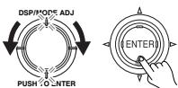
- If the indicators directly above and below the jog dial are lit, turning the jog dial selects a group of settings and pushing the jog dial enters the selected group (i.e. takes you one level down).
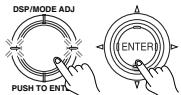
2. Press the jog dial or ENTER button on the remote controller.


ISPERKER CONFIG?
3. Press the jog dial or ENTER button on the remote controller.


ISUBWOOFER YES
4. Turn the jog dial or press the or cursor buttons on the remote controller to set whether or not a subwoofer is connected.

YES: Select when a subwoofer is connected.
NO: Select when a subwoofer is not connected.
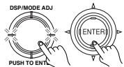
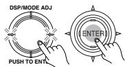
- If the indicators directly to the left and right of the jog dial are lit, turning the jog dial changes the setting of the currently selected parameter and pushing the jog dial displays the next parameter.
LFRONT LARGE
5. Press either the jog dial or the cursor button on the remote controller once.

Then turn the jog dial or press the or cursor button on the remote controller to set the size of your front speakers.


LARGE: Select if the front speakers are large sized.
SMALL: Select if the front speakers are small sized.
- If "NO" is selected for the Subwoofer setting, then this setting is fixed to "LARGE".
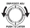
6. Press either the jog dial or the cursor button on the remote controller once.
ICENTER LARGE
Then turn the jog dial or press the or cursor buttons on the remote controller to set whether or not a center speaker is connected and, if one is connected, its size.


NONE: Select if no center speaker is connected.
LARGE: Select if the center speaker is large sized.
SMALL: Select if the center speaker is small sized.
- If "SMALL" is selected for the Front setting, then "LARGE" cannot be selected for this setting.
7. Press either the jog dial or the cursor button on the remote controller once.
ISURROUND =SMALL
Then turn the jog dial or press the or cursor button on the remote controller to set whether or not surround speakers are connected and, if they are connected, their size.


NONE: Select if no surround left and right speakers are connected. LARGE: Select if the surround left and right speakers are large sized.
SMALL: Select if the surround left and right speakers are small sized.
- If "SMALL" is selected for the Front setting, then "LARGE" cannot be selected for this setting.
Pressing the jog dial again or cursor button returns you to the subwoofer setting.
8. Press the RETURN button.


You return to the "SPEAKER CONFIG?" display.
Notes:
- If you press the RETURN button again, you go back up one more level.
- To exit the setup mode immediately, press the SETUP button.
Speaker Distance
These settings tell the TX-DS595 how far away your speakers are located from the listening position so that it can provide the optimum sound space. If you are continuing from setting the speaker configuration and are still in the setup mode, skip directly to step 2.
1. Press the SETUP button.
If anything other than "1. SPEAKER SETUP" appears, turn the jog dial or press the and cursor buttons on the remote controller until "1. SPEAKER SETUP" appears.


L SPEAKER SETUP
2. Press the jog dial or the ENTER button on the remote controller.


Then turn the jog dial or press the cursor button on the remote controller to display "SPEAKER DISTANCE."

LSP DISTANCEP
3. Press the jog dial or the ENTER button on the remote controller.


Then turn the jog dial or press the and cursor buttons on the remote controller to select the unit of measurement.


UNIT FEET
FEET: Select if you will enter the distances in feet.
METERS: Select if you will enter the distances in meters.
4. Press the jog dial or the cursor button on the remote controller.

Then turn the jog dial or press the and cursor buttons on the remote controller to set the distance from the front speakers to the listening position.


LFRONT L'R 12"
You can set the distance in the range of 1 feet (0.3m) - 30 feet (9m) in 1 feet (0.3m) steps.
5. Repeat the procedure in step 4 to set the distance from the center speaker (CENTER) and the surround speakers (SURR L/R) to the listening position.
6. Press the RETURN button.
You return to the "SP DISTANCE?" display.


Notes:
- If you press the RETURN button again, you go back up one more level.
- To exit the setup mode immediately, press the SETUP button.
Level Calibration
These settings allow you to set the volume levels of each speaker individually so that they all sound at the same level when heard from the listening position. If you are continuing from setting the speaker distances and are still in the setup mode, skip directly to step 2.
1. Press the SETUP button.
If anything other than "1. SPEAKER SETUP" appears, turn the jog dial or press the and cursor buttons on the remote controller until "1. SPEAKER SETUP" appears.
L SPEAKER SETUP

2. Press the jog dial or the ENTER button on the remote controller.
Then turn the jog dial or press the cursor button on the remote controller to display the "LEVEL CAL."
LLEKEL CALP
3. Press the jog dial or ENTER button on the remote controller.
A test sound (pink noise) will be heard from the left front speaker. At this point, it is not necessary to adjust the volume of the test sound.
LEFT
4. Press either the jog dial or the cursor button on the remote controller again.
The test sound will now be heard from a different speaker.
5. Turn the jog dial or press the or cursor buttons on the remote controller to adjust the volume of the test sound from this speaker to the same level that you heard from the previous speaker.
You can adjust the level in the range between -12 dB and +12 dB.
6. Repeat the procedure in step 4 and 5 until the volume of the test sound from all speakers is the same level.
Each time you press the jog dial or the button on the remote controller, the test sound will be heard from a different speaker. The speaker order for calibration is LEFT (front left) CENTER (center) RIGHT (front right) SURR RIGHT (surround right) SURR LEFT (surround left) SUBWOOFER (subwoofer).
7. Press the RETURN button.
You return to the "LEVEL CAL?" display.

Notes:
- If you press the RETURN button again, you go back up one more level.
- To exit the setup mode immediately, press the SETUP button.
You can also press the TEST button on the remote controller to perform the Level Calibration setting. For more details, see page 9.
One of the features of the TX-DS595 that is most frequently used is its ability to play FM and AM broadcast radio stations. The TX-DS595 provides a number of listening modes perfect for listening to the radio and getting the most out of your audio system. Also, by presetting radio stations that you listen to frequently, you can select them easily by pressing the CH / = button on the remote controller.
Tuning into a radio station
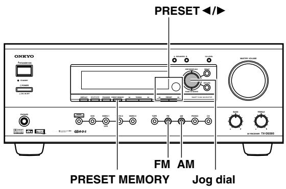
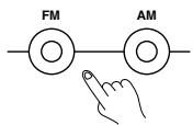
- Press either the AM or FM input source button.
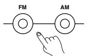
- Using the TUNING and buttons on the front panel, tune into the station you desire.
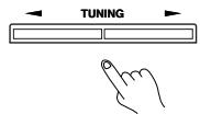
- The tuner frequency changes in 50kHz increments for FM and 10kHz (or 9kHz ) increments for AM.
- When tuning into FM stations, you can press the TUNING or button continuously for more than 0.5 seconds to scan for an FM station in the direction of the button you pressed (FM auto tuning mode). After you release the button and a station is received in stereo, the scanning stops.
- The European model allows you to receive RDS broadcasts. See pages 23 and 24 for a more detailed explanation.
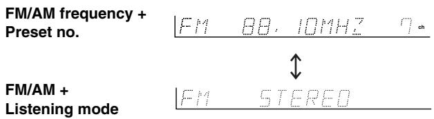
Listening to a stereo radio station (FM mode)
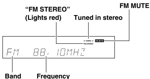
When you tune into a radio station, TUNED indicator appears in the display. If you tune into an FM station in stereo, then "FM STEREO" appears. If the signal is weak, it may be impossible to tune into the station in stereo. In such a case, press the FM MODE button on the front panel. The FM MUTE indicator turns off. At this time, the station will be in mono and interstation noise will be heard.

Presetting a radio station
- Tune into the radio station you desire (see "Tuning into a radio station").
FM 8日,IOMHz
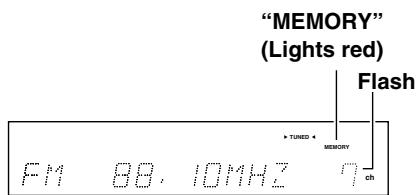
- Press the PRESET MEMORY button on the front panel.
"PRESET IN?" appears in the front display for about five seconds.
IPRESET INP
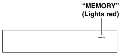
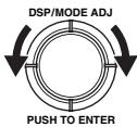
- Press the jog dial.
The MEMORY indicator lights red.

- Turning the jog dial, select a preset number (from 1 to 40) to assign the station to be preset.
- Press the jog dial to finalize the procedure.
This programs the radio station as a preset radio station.
- Up to 40 stations can be stored in memory as preset radio stations.
Selecting a preset radio station
- Press either the AM or FM input source button. The front display should show the currently selected frequency.
If it displays the listening mode, press the DISPLAY button to display the frequency.
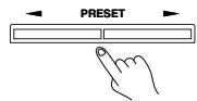
- Press the PRESET / button and select the number of the desired preset station.
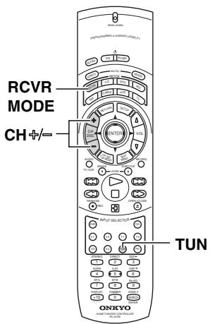
When using the remote controller:
- Press the RCVR MODE button The RCVR MODE button lights gro
- Press the TUN button.
- Press the CH 12 button and select the number of the desired preset station.
Erasing a preset radio station
- Press the AM or FM button and press the PRESET / button to select the preset radio station that you want erase (see above).
HH 88,10HH7 7ch
- Press the PRESET MEMORY button.
"PRESET IN?" appears.
IPRESET INP

- Turn the jog dial to display "PRESET ERASE?"
PRESET ERASEP
- Press the jog dial.
The selected preset station is erased.

Listening to RDS broadcasts
RDS reception is available only on the European model and only in areas where RDS broadcasts are available.
What is RDS?
RDS stands for Radio Data System and is a type of FM broadcasting. RDS was developed within the European Broadcasting Union (EBU) and is available in most European countries. Many FM broadcasting stations now transmit the RDS signals, which provide the additional information required. RDS provides you with various services so that you can choose a station that broadcasts your favorite categories of music, news, or other information.
There are three main classifications of RDS broadcasts. Though they can be tuned into by using the Tuning buttons as normal stations, RDS broadcasts allow you to scan for stations of the type and classification for which you are looking. This makes it much easier for you to find the station you want (see "Performing a PTY scan" and "Performing a TP scan" on page 24). The three main classifications are explained below.
RT: Radio Text
When an RDS station broadcasting RT information is selected, the text information received from the station is displayed.
PTY: Program Type
When an RDS station broadcasting PTY information is selected, the station type (classification) is displayed.
TP: Traffic Program
When an RDS station broadcasting TP information is selected, traffic information will be broadcasted periodically.
Notes:
- In some cases, the characters displayed on the display of the TX-DS595 may not be exactly the same as the ones broadcast by the radio station. Also, unusual characters may appear on the display if the TX-DS595 receives characters that cannot be displayed correctly. This is not a malfunction.
- When an RDS station broadcasting PS information is selected, the name of the station is displayed instead of the frequency.
PTY program types in Europe
The text given in parenthesis is what is actually displayed on the TX-DS595.
None (NONE):
No program type.
News reports (NEWS):
Reports on current events and happenings.
Current affairs (AFFAIRS):
Topical reporting of current affairs, often with a wider range of topics than news reports.
Information (INFO):
General information such as weather forecasts, consumer affairs, medical help, etc.
Sport (SPORT):
Live sports action, sports news, and interviews.
Education (EDUCATE):
Formal educational programs.
Drama (DRAMA):
Radio plays and serials.
Culture (CULTURE):
Cultural programs (including religious affairs).
Science and technology (SCIENCE):
Programs about the natural sciences and technology.
Varied (VARIED):
Speech-based programs not covered by the above categories (e.g., quizzes, panel games, and comedy).
Pop music (POP M):
Popular commercial music, usually from past or present sales charts (e.g., Top 40).
Rock music (ROCK M):
Popular music with an alternative appeal, often not appearing on sales charts.
Middle of the road music (M.O.R. M):
Easy listening music (as opposed to Pop, Rock, or Classical).
Light classics (LIGHT M):
Classical music for general rather than specialist appreciation.
Serious classics (CLASSICS):
Performances of major orchestral works, symphonies, chamber music, etc. (including the Grand Opera).
Other music (OTHER M):
Music styles not covered by the above categories (e.g., Jazz, Rhythm & Blues, Folk, Country, and Reggae).
- Alarm (ALARM):
When an RDS station is making an emergency broadcast, this ALARM will flash on the display.
Displaying Radio Text (RT)
If the station you are currently tuned into is broadcasting RT signals, they will be displayed in the front display on the TX-DS595. If the station does not, this function will be ignored.
- To display the radio text, press the RT/PTY/TP button once.

- If the current station you are listening to is not an RDS station, only the frequency of the station appears.
- If "WAITING" appears on the display, more time is required to receive the RT information. When the information is received, the characters will scroll across the front display.
- If "NO TEXT DATA" appears on the display, RT information is not available.
- The display shows the frequency for 3 seconds and returns to program service name.
Performing a PTY scan
- Press the FM input source button.

- Press the RT/PTY/TP button twice.
The current program type appears on the display.

ROCK M
- Using the jog dial, select the PTY program type you desire.
LIGHT M
- Press the jog dial.
The TX-DS595 will scan until it reaches a station of the program type you selected. It will then stop briefly at that station before continuing on until it reaches the next station. Pressing the jog dial stops the PTY scan at that point. If you press the RT/PTY/TP while "NONE" is displayed, "PTY ?" will appear. In this case, return to step 3.

- Press the jog dial when it reaches the station that you want to listen to.
"NOT FOUND" will appear when no RDS signal is being received from the station.
Performing a TP scan
- Press the FM input source button.
- Press the RT/PTY/TP button three times.
1
< TP> will appear if the current station is broadcasting TP signals. This station will periodically broadcast traffic information. To find a different station, proceed to the next step. Also, if "TP" is displayed, proceed to the next step.
- Press the jog dial.
The TX-DS595 will scan until it reaches a station broadcasting traffic information. If "NOT FOUND" appears on the display, a TP station cannot be located.

Basic operation
To use the remote controller, first press the RCVR button.
1. Press the desired input source button.
TX-DS595
Remote controller
The selected source name appears on the display. If you have selected DVD, CD, or other digital devices, see "Digital Input" on page 29. If you have selected a multichannel input, see "Multichannel" on page 29 and "Enjoying the multichannel input" on page 27.
2. Make sure that the SPEAKERS A indicator is lit on the display. If it is not lit, press the SPEAKERS A button.
(Refer to the "Selecting speakers" section on page 26 for more details.)
3. Start playing the selected input source.
Follow the operating instructions for the source device.
4. Selecting a listening mode.
Select a listening mode. (Refer to this page.)
5. Adjust the volume to an appropriate level.
These controls allow you to adjust the volume of the Front, Center, Surround speakers and subwoofer simultaneously. Turning the control clockwise increases the volume level. Turning the control counterclockwise decreases the volume. (Refer to page 26 for more information.)
- Use the bass and treble controls to adjust the tone.
(Refer to page 26 for more information.)
Selecting a listening mode
Select your desired listening mode using the jog dial.
- Depending on the software that you are playing, SURROUND will be Dolby Digital, DTS, or Dolby Pro Logic II.
Refer to page 28 for more details of listening modes.
Refer to page 30 for sources and listening modes. - When playing Dolby Digital or DTS software, the listening mode will automatically change to Dolby Digital or DTS.
- With Dolby Digital and Dolby Pro Logic II surrounds, you can use the Re-EQ function (for more details, see page 9).
Tip:
You can set in advance a different listening mode for each input source. For more details, see page 30.
When turning the jog dial
The items change as shown below:
DIRECT STEREO SURROUND
ORCHESTRA UNPLUGGED
STUDIO MIX TV LOGIC ALL CH
STEREO DIRECT...
When pressing the jog dial
Each time you press it, the items change as shown below:
DIRECT STEREO SURROUND
ALL CH STEREO DIRECT...
Note:
If you want to switch between Dolby Pro Logic II Movie and Dolby Pro Logic II Music at the TX-DS595, press the jog dial and select "SURROUND" for the listening mode.
When using the remote controller (for more details, see page 9)
- Press the RCVR MODE button.
- Press one of the listening mode buttons, STEREO, DIRECT, A. ST, SURR, DSP , or DSP , to select the listening mode.
Selecting speakers (SPEAKERS A, B)
SPEAKERS A: This button turns on or off the speakers connected to the FRONT SPEAKERS, CENTER SPEAKER, SURROUND SPEAKERS, and SUBWOOFER terminals.
When you listen to surround audio or select multi channel input, be sure to turn on SPEAKERS A.
When the speakers are turned on, the SPEAKERS A indicator lights up.
SPEAKERS B: This button turns on or off the speakers connected to the FRONT SPEAKERS B terminals.
When the speakers are turned on, the SPEAKERS B indicator lights up.
Notes:
- You cannot select surround sound when you are using SPEAKERS B.
- When using the B speakers, the A speakers can only be used for stereo or direct playback, so nothing will be output from the left and right surround speakers during multichannel playback.
Adjusting the volume
Adjusting the main volume adjusts the volume level output from all the speakers connected to the TX-DS595 together. If headphones are connected, this also adjusts the volume heard from the headphone speakers. To adjust the volume, either press the VOL / buttons on the remote controller or turn the MASTER VOLUME dial. To increase the volume, turn the dial clockwise; to decrease the volume, turn the dial counterclockwise. The volume can be set to Min, 1 to 79, and Max.
Adjusting the bass and treble
You can adjust the bass and treble levels using the BASS and TREBLE dials. This function only affects the front left and right speakers. For multichannel sources, these dials will not work if the tone control is set to "OFF." (Refer to page 27.)
Temporarily turning off the sound (Remote controller only)
To turn off the sound momentarily, such as when interrupted by a phone call, press the MUTING button on the remote controller. When pressed, "MUTING" is displayed on the TX-DS595. Press the MUTING button again to turn the sound back on.
Switching the display
While listening to or watching an input source, you can display the information regarding the type of source and signal being input by pressing the DISPLAY button on the TX-DS595 or the remote controller.
When an input source other than FM or AM is selected:
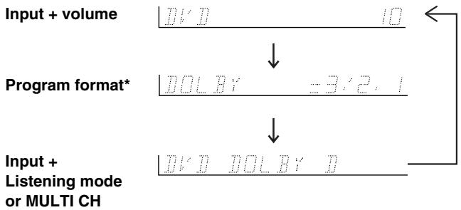
* If the input signal does not have a program format, then this will be skipped.
When FM or AM is selected as the input source:
Using the sleep time (Remote controller only)
The SLEEP button enables you to set the TX-DS595 to turn off automatically after a specified time period. If you press it once, the TX-DS595 will turn off after 90 minutes. Each time it is pressed thereafter, the remaining time until the TX-DS595 turns off decreases by 10 minutes. While, the sleep function is enabled, you can press the SLEEP button to see how much time is left. To cancel the sleep function, press the SLEEP button when the time displayed is less than 10 minutes.
SLEEP 90MIN

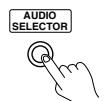
Changing the audio mode
Press the AUDIO SELECTOR button on the front panel (or the AUDIO button on the remote controller) to change the audio mode. Each time the button is pressed, the mode changes from "AUTO" "MULTICH" "ANALOG" and back to "AUTO." The "AUTO" audio mode is recommended for normal circumstances.
AUTO (automatic detection): With this setting, the TX-DS595 automatically detects whether the input signal is digital or analog. When a digital signal is not input, then the analog signal is played.
MULTICH: Select this setting to play back the input from the component connected to the MULTI CHANNEL INPUT port. This setting is effective when the Multichannel setting in the Audio Setup is set to "YES."
ANALOG: Select this setting to play back the input from a source component connected to an analog audio input jacks. With this setting, even if a digital signal is input from the same component, only the analog signal will be output.
Temporarily changing the speaker output levels
To change the individual speaker volumes temporarily, follow the procedure given below. Each channel can be set between -12 to +12 decibels. Note that the calibration settings will return to the original settings when the TX-DS595 is put in standby.
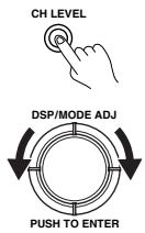
- Press the CH LEVEL button and select the desired speaker.
- Turn the jog dial to adjust the volume level.
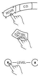
When using the remote controller:
- Press the RCVR MODE button.
- Press the CH SEL button and select the desired speaker.
- Press the LEVEL or button to adjust the volume level.
Notes:
- You cannot select a speaker if the CONFIG parameter of the speaker is set to NO or NONE.
- If the speaker level is set to +1 dB or higher, the maximum level indicated on the display will change if you raise the volume level.
- When you press the TEST button after you set the level, the current level will be used as the value set via the test tone.
Enjoying the multichannel input
Before starting operations, first make sure that the multichannel connection is properly made and that the Multichannel setting of the Input Setup Audio Setup is set to "YES" (see page 29).
- Press the input source button for the component with multichannel output connected to the MULTI CHANNEL INPUT on the rear of the TX-DS595.
- Select "MULTICH" using the AUDIO SELECTOR button on the front panel (AUDIO button on the remote controller).
TX-DS595

Remote controller
- Turn on the connected component and start playing the desired media.
- If necessary, adjust the output level of each speaker as desired (see "Temporarily changing the speaker output levels" on this page).
Adjust the speaker output levels so that you can hear the same sound level from each speaker at the listening position. For the front right, front left, center, surround right, and surround left speakers, the output levels can be adjusted between -12 to +12 decibels. The subwoofer can be adjusted between -30 to +12 decibels.
- Adjust the volume with the MASTER VOLUME dial or the VOL buttons on the remote controller.
Using the tone control:
To make the BASS and TREBLE dials work for multichannel sources, you must first set the tone control to "ON."
- Turn the tone control on by pressing either the jog dial on the TX-DS595 or the DIRECT button on the remote controller.
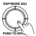
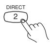
When pressed only once, the current setting appears, so press twice to change the setting.
- Adjust the tone using the BASS and TREBLE dials.
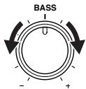
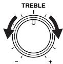
Notes:
- Adjusting the volume level of each speaker for the MULTI CH INPUT source does not affect the speaker level adjusted by the listening position.
- If the speaker level is set to +1 dB or higher, the maximum level indicated on the display will change if you raise the volume level.
The TX-DS595's surround sound enables you to enjoy the presence of a movie theater or concert hall in your room.
The configuration of the speakers are very important for the surround sound. Refer to "Connecting speakers" on page 15.
Before using a listening mode, make sure the Speaker Setup parameters have been set (refer to page 19). Once the parameters have been set, it is not necessary to set them again. Refer to page 25 for information regarding how to select the listening mode.
Listening modes
Stereo
This mode has all input sounds output from the left and right front speakers.
Direct
This mode delivers pure sound with minimum sound quality adjustment and filtration. The sound recorded for the right and left front channels is output to the right and left front speakers only and not output to the subwoofer.
Surround modes
With this mode, decoding is performed automatically to match the input signal. This original mode adds no sound processing to the input signal.
- Dolby D (Dolby Digital)
Digital data with AC-3 compression and a maximum of 5.1-channel* surround sound. This source signal comes from DVDs and LDs that have the [[[[[[[[[[[[[[[[[ [[[[[[[[[[[[[[[[[]]]]]]]]]]] mark and therefore recorded for 5.1-channel output. This source also comes from digital satellite broadcasts that support dolby Digital.
DTS
DTS (Digital Theater System) is compressed digital data with a maximum 5.1-channel* surround output that allows for an extremely high-quality sound. This source signal requires a DVD player that supports DTS output and comes from compact discs, DVDs, and LDs that have the mark.
Notes on DTS:
- If you play a CD or LD that supports DTS when the "ANALOG" setting is selected on the TX-DS595, the DTS encoded signal will not be decoded and noise will be output. This noise could damage the amplifier and speakers. Therefore, be sure to select "AUTO" and use the digital input jacks (OPTICAL or COAXIAL) to connect the DTS source.
- The DTS indicator on the TX-DS595 lights while a DTS source is played. When playback finishes and the DTS signal transmission stops, the TX-DS595 remains in DTS mode and the DTS indicator remains lit. This prevents noise when you operate the pause or skip button on the player. Therefore, if the source is immediately switched from DTS to PCM, the PCM signal may not be played. In this case, stop the playback of the source on the player for about three seconds and then resume playback.
- If you press the pause or skip button on the player while playing a DTS source, on rare occasions a short noise may be heard. This is not a malfunction.
- You may not be able to play some DTS source signals from certain CD players and LD players even if you connect the player to the TX-DS595 digitally. This is because the digital signal has been processed (such as the output level, sampling frequency, or frequency response) and the TX-DS595 cannot recognize the signal as DTS data. Therefore you may hear noise when you play a DTS source while processing the
signal.
- The outputs for the VIDEO 1 OUT and TAPE OUT output analog audio signals. Do not record from CDs or LDs that support DTS using these outputs. If you do, the DTS-encoded signal will be recorded as noise.
- The 5.1-channel digital surround format has a variety of versions including Dolby Digital and DTS. The 5.1- channel digital surround format enables you to individually record and play five full-range (20 Hz to 20 kHz) channels (left and right front, center, and two surround channels) plus an LFE channel (Low Frequency Effect) for the low-range effect sound. It will create a realistic sound that can be heard in the theaters and concert halls.
DOLBY PRO LOGIC II Surround
This mode is a new generation 5-channel surround system that provides performance between the 4-channel (left front, right front, center, and monaural surround) Pro Logic Surround and the 5.1-channel Dolby Digital Surround. This mode can be set to the Movie mode designed for playing movies and the Music mode designed for listening to music. The Movie mode is monaural except for a stereo narrow band for the surround channels. The result is movie viewing with a realistic feel of movement. The Music mode uses the surround channels to provide a natural sound space that cannot be provided with normal stereo output.
This mode can be used with VHS and DVD videos with the DOLLEY SURROUND mark and certain television programs. The Music mode can be used with music compact discs and other stereo sources.
You can press the SURR button on the remote controller to switch between MOVIE and MUSIC. The initial setting is MOVIE. This setting can be made for each input source.
If no surround speakers are connected, then the surround sound is divided and output from the front left and right channels (3 stereo).
Re-EQ function
You can use the Cinema Re-Equalization function when playing back sources in the Dolby Digital Surround and Dolby Pro Logic II Surround modes (see page 9).
LATE NIGHT
When using Dolby Digital, you can use the LATE NIGHT function (see page 32).
Orchestra
This mode is appropriate for classical and opera music. The center channel is cut and the surround channels are emphasized to widen the stereo image. It will simulate the natural reverberation that is created in large halls.
TV Logic
This mode gives realistic acoustics to TV programs that are aired from TV studios. It enhances the entire surround sound and clarity of the conversation.
Unplugged
This mode is suitable for acoustical instrumental sounds, vocals, and jazz music. By emphasizing the front stereo image, it will simulate the acoustics that you would experience in front of the stage.
Studio-Mix
This mode is for rock and popular music. The lively sounds are enhanced for a powerful acoustic image that simulates the feeling of being in a club or rock concert.
All Ch Stereo
This mode is designed for playing background music. The front, surround, and surround back channels create a stereo image that encompasses the entire area.
2. Input Setup
These settings can be set differently for each input source.
Audio Setup
Digital Input (D. INPUT): This setting tells the TX-DS595 which input source button on the front panel is connected with which digital input jack on the rear panel.
If you have connected your components in accordance with the default settings (given in the table below), then there is no need to change this setting.
Multichannel (MULTICH): This setting will not appear if AM or FM is selected at the front panel for the input source. The initial settings are "Yes" for the DVD input source and "No" for all other input sources. This setting is normally set to "NO," and only needs to be changed to "YES" if a DVD player, MPEG decoder, or other component that has a multi channel port is connected to the MULTI CHANNEL INPUT port for 5.1-channel audio.
Default setting
| Input source | Digital input | Multichannel |
| DVD | COAX 1 | Yes |
| VIDEO 1 | COAX 2 | No |
| VIDEO 2 | ---- | No |
| VIDEO 3 | OPT 2 | No |
| VIDEO 4 | ---- | No |
| TAPE | ---- | No |
| FM | ||
| AM | ||
| PHONO | ---- | No |
| CD | OPT 1 | No |
----: No setting : Not applicable
OPT1: Select if connected to DIGITAL INPUT (OPTICAL) 1.
OPT2: Select if connected to DIGITAL INPUT (OPTICAL) 2.
COAX1: Select if connected to DIGITAL INPUT (COAXIAL) 1.
COAX2: Select if connected to DIGITAL INPUT (COAXIAL) 2.
----: Select if the input source is not from a digital input jack.
Notes:
- Do not assign a digital input to more than one input source. If you are making a digital connection that requires you to change the default settings, be sure to always first cancel the current digital input setting and then assign the new setting.
- When playing a device that is actually connected to the MULTI CHANNEL INPUT terminal, select MULTICH with the AUDIO SELECTOR button (see page 27).
Audio Setup procedure
1. Select the desired input source.
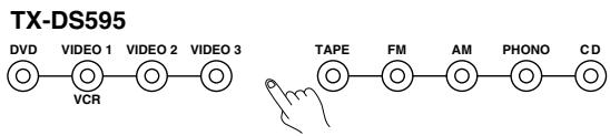
Remote controller
2. Press the SETUP button.

Turn the jog dial or press the and cursor buttons on the remote controller to display "2. INPUT SETUP."
3. Press the jog dial or ENTER button on the remote controller.
"AUDIO SETUP?" appears in the front display.
4. Press the jog dial or ENTER button on the remote controller.
The name of the digital input currently assigned to the selected input source appears.
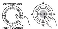
5. Turn the jog dial or press the or cursor button on the remote controller to select the digital input.
(Example: If connected to COAX 1.)
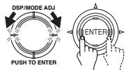

6. Press either the jog dial or the cursor button on the remote controller.
"MULTICH=YES" or "NO" appears.
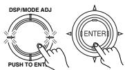
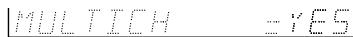
If a component with a 5.1-channel output terminal is connected (i.e., DVD player or MPEG decoder), turn the jog dial or press the and buttons on the remote controller to select "YES."
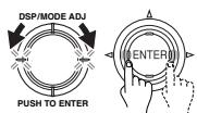
7. Press the RETURN button.
"AUDIO SETUP?" appears in the front display.

To exit the setup mode immediately, press the SETUP button.

Listening Mode Preset
With the TX-DS595, you can set a different listening mode for each different signal type that comes from each input source.
For example, with the default settings, even when using the same DVD player, if a CD is played, the listening mode automatically becomes "STEREO," and if a DVD is played (Dolby Digital 3/2.1), the listening mode automatically becomes Dolby D.
Analog/PCM Source: Set a listening mode for the input signal from 2-channel analog sources and PCM source (default: STEREO.)
Note:
For PCM sources recorded at a sampling rate of 96kHz or greater, only the Stereo or Direct listening modes can be selected. However, the set listening mode is stored in memory.
Digital format Source: Set a listening mode for the input signal from digital sources (default: SURROUND).
1. Select the desired input source.
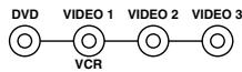
TX-DS595
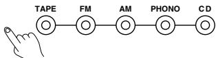
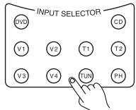
Remote controller
2. Press the SETUP button.
Turn the jog dial or press the and cursor buttons on the remote controller to display "2. INPUT SETUP."
3. Press the jog dial or ENTER button on the remote controller.
Turn the jog dial or press the cursor button on the remote controller to display "LSTNMODEPRESET?".
4. Press the jog dial or ENTER button on the remote controller.
The listening mode when playing an analog/ PCM source with the currently selected input source appears.


IPC1=STEREO
5. Turn the jog dial or press the or cursor buttons on the remote controller to select the listening mode.
Refer to the table to see what listening modes are available.


6. Press either the jog dial or the cursor button on the remote controller.
The listening mode when playing a digital format source with the currently selected input source appears.
ID:FMT=SURROUND
7. Turn the jog dial or press the or cursor button on the remote controller to select the listening mode.
Refer to the table to see what listening modes are available.
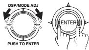
8. Press the RETURN button.
"LSTNMODEPRESET?" appears in the front display.

To exit the setup mode immediately, press the SETUP button.

Relationship between input source and listening mode
| Input source signal (display) | Analog/PCM Source | Digital Format | ||
| Type of media Listening Mode | Tape, CD, Record, Tuner DVD Video (PCM), LD (PCM) Digital satellite broadcast | DVD, Digital satellite broadcast, DTS-CD | ||
| Dolby Digital 2ch Source | DTS, All excluding Dolby Digital 2ch | |||
| Direct | ● | |||
| Stereo | ● | ● | ● | |
| Surround | Pro Logic II (Movie) | ● | ● | |
| Pro Logic II (Music) | ● | ● | ||
| Dolby Digital | ● | |||
| DTS | ● | |||
| Orchestra | ● | |||
| Unplugged | ● | |||
| Studio-Mix | ● | |||
| TV Logic | ● | |||
| All Ch Stereo | ● | |||
Notes:
-
The listening modes that can be set are different for each input source format.
-
You may not be able to select all the listening modes shown here depending on your speaker configuration or the selected input source.
IntelliVolume
When switching input sources, you may find that the output level for different components or input sources connected to the TX-DS595 is different even though the main volume setting is the same. Under normal circumstances, you would then have to change the volume setting each time you change the input source. This IntelliVolume allows you to preset a volume level for each input source separately so that when you do switch from one input source to another, the TX-DS595 adjusts the volume accordingly so that the resulting volume stays the same.
1. Select the desired input source.
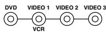
TX-DS595
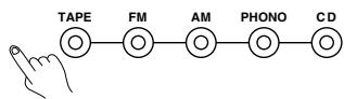
Remote controller
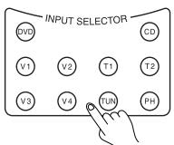
2. Press the SETUP button.


Turn the jog dial or press the and cursor buttons on the remote controller to display "2. INPUT SETUP."


3. Press the jog dial or ENTER button on the remote controller.


Turn the jog dial or press the cursor button on the remote controller to display "INTELLIVOLUME?".


4. Press the jog dial or ENTER button on the remote controller.


5. Turn the jog dial or press the and cursor buttons on the remote controller to set the IntelliVoleme.


It can be adjusted between -12 and +12 decibels.
6. Press the RETURN button.


"INTELLIVOLUME?" appears in the front display.
To exit the setup mode immediately, press the SETUP button.


3. Preference
Volume Setup
Maximum Volume (MAXIMUM VOL): This setting allows you to set the maximum volume that can be output with the MASTER VOLUME dial to prevent components from being damaged by excessively loud volumes. When Maximum Volume is not set, set this to OFF.
Power On Volume (POWERONVOL): This sets a designated volume setting for the TX-DS595 to be set every time that the power is turned on. This prevents the TX-DS595 from being turned on while it is set to an extremely high volume and suddenly output very loud sounds.
1. Press the SETUP button.
Turn the jog dial or press the and cursor buttons on the remote controller to display "3. PREFERENCE."
2. Press the jog dial or ENTER button on the remote controller.
"VOLUME SETUP?" appears in the front display.
3. Press the jog dial or ENTER button on the remote controller.
"MAXIMUM VOL=" appears in the front display.
4. Turn the jog dial or press the or cursor button on the remote controller to set the maximum volume.
The maximum volume can be set between 30 and 79.
5. Press either the jog dial or the cursor button on the remote controller.
"POWER ON VOL" appears in the front display.
6. Turn the jog dial or press the or cursor button on the remote controller to set the power on volume.
The power on volume can be set between "MIN" and the value set for "MAXIMUM VOL." If you do not mind having the TX-DS595 turned on with its current volume setting, set this to "LAST."
7. Press the RETURN button.
"VOLUME SETUP?" appears in the front display.
To exit the setup mode immediately, press the SETUP button.
Headphones Level
You can use this setting to adjust the volume output from the headphones so that it matches the level output from the speakers.
1. Press the SETUP button.
Turn the jog dial or press the and cursor buttons on the remote controller to display "3. PREFERENCE."
2. Press the jog dial or ENTER button on the remote controller.
Turn the jog dial or press the cursor button on the remote controller to display "HEADPHONES LVL?".
3. Press the jog dial or ENTER button on the remote controller.
"HP LEVEL" appears in the front display.
4. Turn the jog dial or press the or cursor button on the remote controller to set the headphone volume.
The headphone volume can be adjusted between -12 and +12 decibels.
5. Press the RETURN button.
"HEADPHONES LVL?" appears in the front display.
To exit the setup mode immediately, press the SETUP button.
AM Frequency step Setup
This screen only appears on the worldwide model. The initial setting is 9 kHz, and this needs only to be changed if you are using the TX-DS595 in a 10-kHz region.
1. Press the SETUP button.
Turn the jog dial or press the and cursor buttons on the remote controller to display "3. PREFERENCE."
2. Press the jog dial or ENTER button on the remote controller.
Turn the jog dial or press the cursor button on the remote controller to display "AM FREQ STEP?".
3. Press the jog dial or ENTER button on the remote controller.
The currently set frequency step appears.
4. Turn the jog dial or press the or cursor buttons on the remote controller to set the frequency.
5. Press the RETURN button.
"AM FREQ STEP?" appears in the front display.
To exit the setup mode immediately, press the SETUP button.
Late Night Setup
Sets "HIGH," "LOW," or "OFF" for the late night function.
Cinema sound has a vast dynamic range; therefore, to hear the quieter sounds such as human conversations, they must be played back at larger volumes. When this parameter is set to "HIGH" or "LOW," the dynamic range of the sound is narrowed down to allow you to easily hear minute sounds at low volumes. This function is especially useful if you wish to play a movie at low volumes during the nighttime.
1. Press the SETUP button.
Turn the jog dial or press the and cursor buttons on the remote controller to display "3. PREFERENCE."
2. Press the jog dial or ENTER button on the remote controller.
Turn the jog dial or press the cursor button on the remote controller to display "LATE NIGHT?".
3. Press the jog dial or ENTER button on the remote controller.
The current setting appears.
4. Turn the jog dial or press the or cursor buttons on the remote controller to set the late night function.
5. Press the RETURN button.
"LATE NIGHT?" appears in the front display.
To exit the setup mode immediately, press the SETUP button.
Notes:
- The depth of the Late Night effect is determined by Dolby Digital software. Some sounds may produce no or little effect.
- The Late Night function is effective only on Dolby Digital encoded software.
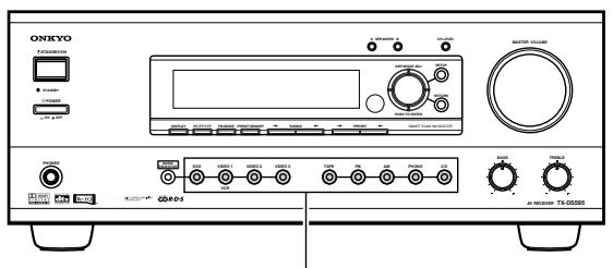
Input source buttons
The TX-DS595 can also be used to record an input source media. This allows you to make copies of the music or videos you like, copy them from one type of media to another, or even record what is being broadcast on television or radio.
Recording an audio source
Make all connections between the tape deck and the receiver as shown in the "Connections" diagram (pages 11-13).
1. Insert a blank tape into the tape deck.
2. Press the input source button for the source you want to record.
- If you select DVD,VIDEO 1,VIDEO 2, orVIDEO 3, only the audio will be recorded.
- If you select FM or AM, set the tuner to the station you want to record.
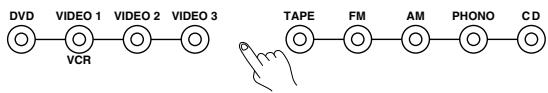
3. Set the tape deck in recording mode. Start playing the source.
Set the proper recording level using the controls on the tape deck.
Recording data from a video disc player (or a video camcorder) to VCR
Video disc programs can be recorded onto a VCR (VIDEO 1).
- Load a disc in the video disc player or DVD player, and insert a blank tape in the VCR (VIDEO 1).
- Press theVIDEO 2,VIDEO 3, or DVD button.
- Start playing the source and recording on the VCR.
Refer to the video equipment connections section on the page 12.
Tip:
If you want to record the video from one source and the audio from another source together, such as recording the video from a video camera connected to VIDEO 2 and the audio from a CD player connected to CD, in step 2 above, select the source for the video and then select the source for the audio. The remaining procedure is the same as that above.
Notes:
- If you change the input source during recording, you will record the signals from the newly selected input source.
- You cannot record the surround effects.
- You cannot perform digital recording with the TX-DS595. Also, digital-to-analog signal conversion is not possible, so to record audio signals from digital sources (e.g. CD players), you must not only make the digital connection, but the analog connection as well.
- You cannot record the source connected to the MULTI CHANNEL INPUT connector.
Overview
The RC-447M remote controller is a useful tool to help you operate the components of your home theater. To do so, first press the Mode button that corresponds to the device you wish to control. Then simply press the desired operation button and the component will operate accordingly. For example, if you wish to select the CD input source at the TX-DS595 with the remote controller, first press the RCVR MODE button to select the TX-DS595 and then press the CD (INPUT SELECTOR) button.
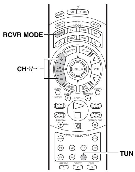
Calling up a preset radio station
- Press the RCVR MODE button
The RCVR MODE button lights green. - Press the TUN input selector button.
- Press the CH + or - button to select the desired preset station number.
Controlling an Onkyo cassette tape deck
The RI connector of the Onkyo cassette tape deck must be connected to the TX-DS595 (see page 13).
- Press the RCVR MODE button.
The RCVR MODE button lights green.
- Press the desired operation button.
The buttons shaded in the figure to the left are the operation buttons that can be used to control an Onkyo cassette tape deck.
Operation buttons:
:Play
: Stop
: Rewind
: Fast forward
: Press during playback to skip to the beginning of the next track.
: Press during playback to skip to the beginning of the current track.
REC: Record/Pause
: Reverse playback
You may also use the following buttons:
VOL / : Adjusts the volume at the TX-DS595
MUTING: Activates the muting function at the TX-DS595
Note:
Even for devices with the and buttons, signal discrepancies may cause them not to work properly.
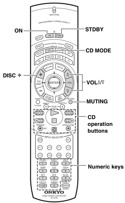
Controlling an Onkyo CD player
The RI connector of the Onkyo compact disc player must be connected to the TX-DS595 (see page 13).
- Press the CD MODE button.
The CD MODE button lights green.
- Press the desired operation button.
The buttons shaded in the figure to the left are the operation buttons that can be used to control an Onkyo compact disc player.
Operation buttons:
ON: Turns on and off the compact disc player (same as STDBY button on the remote controller).
DISC : Selects a disc in the CD changer
Track down
Track up
:Play
: Stop
: Fast reverse
: Fast forward
:Pause
OPEN/CLOSE Open/close the disc tray
0,1 to 9,+10: Numeric keys
RANDOM: For random playback.
You may also use the following buttons:
VOL / : Adjusts the volume at the TX-DS595
MUTING: Activates the muting function at the TX-DS595
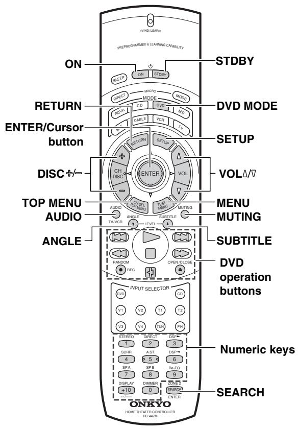
Controlling an Onkyo DVD player
The RI connector of the Onkyo DVD player must be connected to the TX-DS595 (see page 13).
1. Press the DVD MODE button.
The DVD MODE button lights green.
2. Press the desired operation button.
The buttons shaded in the figure to the left are the operation buttons that can be used to control an Onkyo DVD player.
Operation buttons:
ON: Turns the DVD player on and off.
STDBY: Turns the DVD player off. (Some sets may not respond to this button. In this case, use the ON button to put the DVD player in the standby state.)
SETUP: Displays the menu.
/ / < > :Moves the cursor.
ENTER: Confirms the selection.
RETURN: Return button
TOP MENU or MENU: Displays the menu screen(s) recorded on DVD media.
DISC 十 / = : Selects a disc in the DVD changer.
AUDIO: Press repeatedly to select an audio and/or language track recorded on a DVD-Audio/Video.
ANGLE: Press repeatedly to select a camera angle when a DVD-Video is recorded with multiple angle playback.
SUBTITLE: Press repeatedly to select one of the subtitle languages recorded on a DVD-Video.
SEARCH: Press to find the specific section on a disc where you want to start playback.
RANDOM: Press to start random playback.
: Chapter/Track down
Chapter/Track up
:Play
: Stop
:Fast reverse
: Fast forward
:Pause
OPEN/CLOSE Open/close the disc tray
0, 1 to 9, +10: Numeric keys
You may also use the following buttons:
VOL : Adjusts the volume at the TX-DS595
MUTING: Activates the muting function at the TX-DS595
Note:
When operating an Onkyo DVD player directly with the remote controller without connecting the RI terminals, pre-programming is necessary (see page 38).
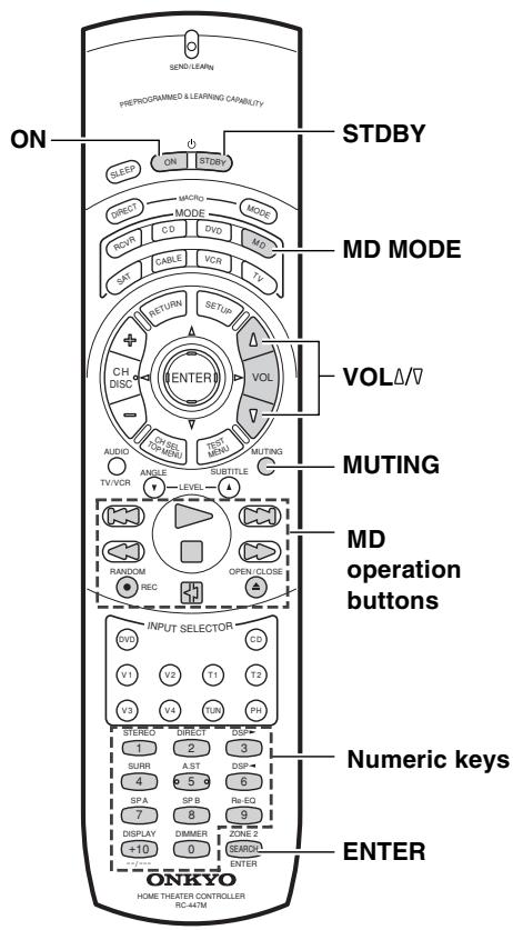
Controlling an Onkyo MD recorder
The RI connector of the ONKYO MD recorder must be connected to the TX-DS595 (see page 13).
- Press the MD MODE button.
The MD MODE button lights green.
- Press the desired operation button.
The buttons shaded in the figure to the left are the operation buttons that can be used to control an Onkyo MD recorder.
Operation buttons:
ON: Turns on and off the MD player (same as STDBY button on the remote controller).
Track down
Track up
:Play
□: Stop
:Fast reverse
:Fastforward
REC: Record
:Pause
:Eject the disc
1 to 9,0,--:/----: Numeric keys
ENTER: Enters the settings
You may also use the following buttons:
VOL / : Adjusts the volume at the TX-DS595
MUTING: Activates the muting function at the TX-DS595
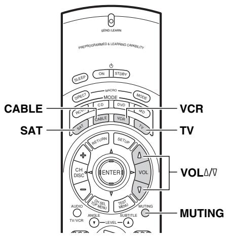
SAT, CABLE, VCR, and TV MODE buttons
No preset codes are programmed into the SAT, CABLE, VCR, and TV MODE buttons. You can use these buttons to program the remote controller signals of other devices.
There are two methods. One method is selecting the name of a different brand from the table, entering the setting number listed, and calling up the pre-programming code (see page 38). The other method is learning the commands from the other brand's remote control directly into this remote controller (see page 42).
When in the SAT, CABLE and VCR mode, you may use the following buttons:
VOL : Adjusts the volume at the TX-DS595
MUTING: Activates the muting function at the TX-DS595
The remote controller has three learning functions. One is entering the signal number for a remote controller of another brand that is preprogrammed. Another is a normal learning function that enables the remote controller to learn the codes from other remote controllers. And the last is a macro learning function that enables you to program a series of operations into the remote controller so that the operations can all be performed at once by pressing one button.
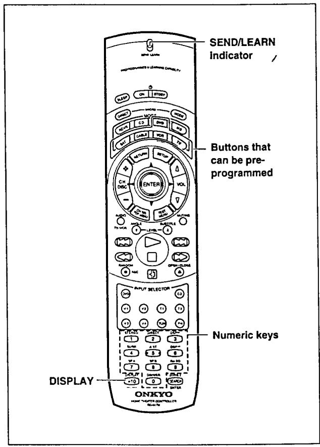
Caution
With some brand's components, some buttons may not work correctly. In this case, program the command separately.
Learning a pre-programming code
By learning a pre-programming code, you can make the RC-447M remote controller able to operate a product from another brand. The buttons that are used for operation are given on the next page.
- Find the 3-digit number for the brand name of the component that you want to operate in the table on the next page.
- Turn on the component that you want to operate (i.e. DVD, satellite tuner, or television).
- While holding down the MODE button on the RC-447M that you want to program, press the DISPLAY button, and then release both buttons.
The SEND/LEARN indicator lights when the MODE button is pressed and turns off when the DISPLAY button is pressed. Wait until the indicator turns off before releasing both buttons. Then the SEND/LEARN indicator lights again.
- Within 30 seconds, enter the 3-digit code number.
The SEND/LEARN indicator flashes twice slowly. If the SEND/LEARN indicator quickly flashes three times, then either a mistaken 3-digit code was entered or an incorrect operation was performed. If this occurs, return to step 3.
- Press the button that you programmed and check if the system operates correctly.
If the component turns off, the code is correct. If the component does not turn off, return to step 3.
- If it still does not operate properly, then program the commands one by one to the buttons on the RC-447M remote controller.
When entering the code of Onkyo DVD players:
There are three SETTING numbers. Choose the SETTING number according to how you will be using the DVD player.
No. 601/613: These codes are for operating the Onkyo DVD player by pointing the remote controller directly at it, either because it does not have an Rl terminal, or it does but you are not using an Rl cable and connecting it. First enter 601 and if it does not operate properly, enter 613.
No. 600: This code is for Onkyo DVD players that have an RI terminal that you are connecting to the TX-DS595 with an RI cable. You will then operate the DVD player by pointing the remote controller at the remote control sensor on the TX-DS595. You do not need to enter this code because it is factory preset. However, if the code has been changed to 601 or 613, then you will need to change it back to 600.
Pre-programmong codes
Note:
If more than one code is given in the table, try the code one by one until you reach the code for your component (i.e. if the first code does not work, then try the next).
DVD
| BRAND | SETTING No. |
| DENON | 602, 609 |
| HITACHI | 603 |
| JVC | 604 |
| KENWOOD | 605 |
| MAGNAVOX | 606, 613 |
| MARANTZ | 607 |
| MITSUBISHI | 608, 613 |
| ONKYO | 600, 601, 613 |
| PANASONIC | 609 |
| PIONEER | 610 |
| PROSCAN | 611 |
| RCA | 611 |
| SONY | 612 |
| TOSHIBA | 613 |
| YAMAHA | 609, 614 |
| ZENITH | 613, 615 |
SAT
| BRAND | SETTING No. |
| ECHOSTAR | 700 |
| GENERAL INSTRUMENTS | 701 |
| HITACHI | 702 |
| HUGHEs NETWORK SYSTEMS | 703 |
| PANASONIC | 704 |
| PRIMESTAR | 705 |
| PROSCAN | 706, 707 |
| RCA | 706, 707 |
| SONY | 708 |
| TOSHIBA | 709 |
CABLE
| BRAND | SETTING No. |
| GENERAL INSTRUMENTS | 500 |
| GEMINI | 501 |
| HAMILIN | 502, 503, 504, 505 |
| JERROLD | 500, 506, 507, 508, 509, 510, 511, 512, 513, 514 |
| MACOM | 515, 516, 517 |
| MAGNAVOX | 518 |
| OAK | 519, 520, 521 |
| PANASONIC | 522, 523 |
| PHILIPS | 524, 525, 526, 527, 528, 529 |
| PIONEER | 530, 531 |
| SCIENTIFIC ATLANTA | 532, 533, 534 |
| SAMSUNG | 535 |
| TOCOM | 536 |
| ZENITH | 537, 538 |
VCR
| BRAND | SETTING No. |
| AIWA | 300, 301, 302 |
| AKAI | 303, 304, 305, 306, 307 |
| BAIRD | 308 |
| BELL & HOWELL | 309 |
| BLAUPUNKT | 310 |
| CGM | 311, 312, 313 |
| COLTINA | 314 |
| DAEWOO | 315, 316 |
| DIGITAL | 317 |
| EMERSON | 318, 319, 320, 321, 322 |
| FENNER | 323 |
| FISHER | 324, 325, 326, 327 |
| FUJITSU GENERAL | 328 |
| FUNAI | 329 |
| GE | 330, 331 |
| GO VIDEO | 332, 336, 337 |
| GOLDSTAR | 333, 334 |
| GOODMANS | 335 |
| GRUNDIG | 338 |
| HITACHI | 339, 340, 341 |
| JVC | 342, 343, 344, 345, 346, 347, 348, 349, 350 |
| LOEWE | 351, 352 |
| MAGNAVOX | 353, 354, 355 |
| MITSUBISHI | 356, 357, 358, 359, 360, 361, 362, 363, 364 |
| NEC | 365, 366, 367 |
| NOKIA | 313 |
| NORDMENDE | 368, 369, 370 |
| OKANO | 371, 372 |
| ORION | 319, 373 |
| PANASONIC | 374, 375, 376, 377, 378 |
| PHILIPS | 353, 379, 380 |
| PHONOLA | 311 |
| PIONEER | 381 |
| RCA | 382 |
| SABA | 383 |
| SAMSUNG | 384, 385, 386, 387, 388, 389, 390 |
| SANYO | 391, 392, 393 |
| SCOTT | 394 |
| SELECO | 395 |
| SHARP | 396, 397, 398, 399 |
| SHINTOM | 400 |
| SIEMENS | 401 |
| SONY | 402, 403, 404, 405, 406, 407, 408, 409, 410, 411, 412, 413 |
| SYMPHONIC | 414 |
| TEKNIKA | 414, 415 |
| TELEFUNKEN | 416, 417 |
| TOSHIBA | 418, 419, 420 |
| WHITE | |
| WESTINGHOUSE | 333 |
| WATSON | 421 |
| ZENTH | 422 |
TV
| BRAND | SETTING No. |
| AIWA | 100, 101 |
| AKAI | 102, 103, 104 |
| AUDIOSONIC | 105 |
| BELL & HOWELL | 106 |
| BLAUPUNKT | 107 |
| BRIONVEGA | 108, 109 |
| CENTURION | 110 |
| COLTINA | 111, 112, 113 |
| CORONAD | 114 |
| CROWN | 115, 116 |
| DAEWOO | 117, 118, 119, 120, 121 |
| DUAL | 122 |
| EMERSON | 123, 124, 125, 126, 127 |
| FENNER | 128, 129 |
| FERGUSON | 130, 131 |
| FISHER | 132 |
| FUNAI | 133, 134, 135 |
| FUJITSU GENERAL | 136, 137, 138 |
| GE | 139, 140, 141 |
| GOLDSTAR | 142, 143 |
| GOODMANS | 144 |
| GRUNDIG | 145, 146 |
| HITACHI | 147, 148, 149, 150 |
| HYPER | 151 |
| INNO HIT | 152 |
| IRRADIO | 103 |
| JVC | 153, 154, 155, 156, 157 |
| KENDO | 158 |
| KTV | 159, 160 |
| LUXOR | 161 |
| MAGNAVOX | 162, 163 |
| MARANTZ | 164 |
| MARK | 165 |
| MATSUI | 166, 167, 168, 169 |
| MITSUBISHI | 170, 171, 172, 173 |
| MIVAR | 174, 175 |
| NEC | 176, 177 |
| NOKIA | 178, 179, 180, 181 |
| OCEANIC | 181 |
| NORDMENDE | 182, 183 |
| OKANO | 152 |
| ORION | 184, 185, 186 |
| PANASONIC | 187, 188, 189, 190 |
| PHILIPS | 152, 162, 191 |
| PIONEER | 192, 193 |
| PROSCAN | 194 |
| QUASAR | 195 |
| RADIO SHACK | 196 |
| RCA | 110, 141, 197, 198, 199, 200 |
| SABA | 182, 183, 201 |
| SAMSUMG | 202, 203, 204, 205, 206, 207, 208 |
| SANYO | 209, 210, 211, 212 |
| SCHNEIDER | 103 |
| SEARS | 213 |
| SELECO | 214, 215 |
| SHARP | 216, 217 |
| SONY | 218, 219, 220, 221, 222, 223 |
| SYMPHONIC | 224, 225 |
| TELEFUNKEN | 201, 226, 227 |
| THOMSON | 228 |
| TOSHIBA | 213, 229 |
| UNIVERSUM | 230 |
| ZENITH | 231, 232 |
After performing the procedure given above, the following modes become enabled for use.
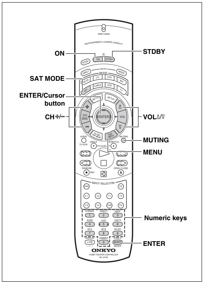
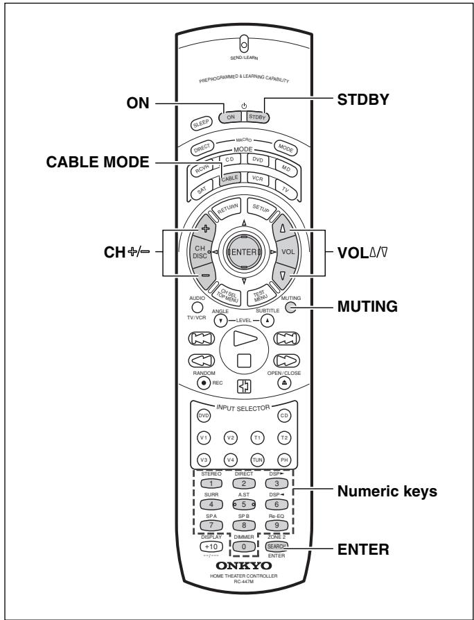
DVD MODE (DVD Player Mode)
Buttons with programmed usage and operations are the same as the operational buttons on page 36.
SAT MODE (Satellite Tuner Mode)
- Press the SAT MODE button.
The SAT button lights green.
- Press the desired operation button.
The buttons shaded in the figure to the left are the operation buttons that can be used to control your satellite tuner unit.
The buttons given below have operations programmed into them.
ON: Turns on and off the satellite tuner unit (same as STDBY button on the remote controller)
CH / = : Moves up and down the preset channel numbers
/ / < > :Moves the cursor
ENTER: Confirms the selection
MENU: Displays the menu
0,1 to 9: Numeric keys
ENTER: Confirm
You may also use the following buttons:
VOL / : Adjusts the volume at the TX-DS595
MUTING: Activates the muting function at the TX-DS595
CABLE MODE (Cable Tuner Mode)
- Press the CABLE MODE button.
The CABLE button lights green.
- Press the desired operation button.
The buttons shaded in the figure to the left are the operation buttons that can be used to control your cable tuner unit.
The buttons given below have operations programmed into them.
ON: Turns on and off the cable tuner unit (same as STDBY button on the remote controller)
CH / - :Movesupanddownthepreskchanne numbers
0,1 to 9: Numeric keys
ENTER: Confirm
You may also use the following buttons:
VOL / : Adjusts the volume at the TX-DS595
MUTING: Activates the muting function at the TX-DS595
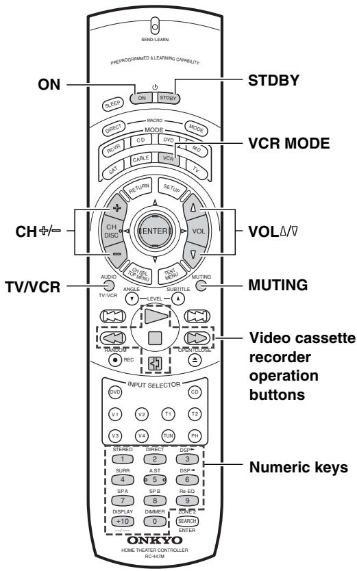
VCR MODE (VCR Mode)
1. Press the VCR MODE button.
The VCR button lights green.
2. Press the desired operation button.
The buttons shaded in the figure to the left are the operation buttons that can be used to control your VCR.
The buttons given below have operations programmed into them.
ON: Turns on and off the VCR (same as STDBY button on the remote controller)
CH +- = : Moves up and down the preset channel numbers
TV/VCR: Switches the AV input for the VCR
:Play
□: Stop
: Rewind
:FastForward
: Pause
0,1 to 9, +10: Numeric keys
You may also use the following buttons:
VOL / : Adjusts the volume at the TX-DS595
MUTING: Activates the muting function at the TX-DS595
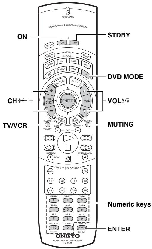
TV MODE (TV Mode)
1. Press the TV MODE button.
The TV button lights green.
2. Press the desired operation button.
The buttons shaded in the figure to the left are the operation buttons that can be used to control your television.
The buttons given below have operations programmed into them.
ON: Turns on and off the television (same as STDBY button on the remote controller)
CH 12 = : Moves up and down the television channels
TV/OCR: Switches the TV/OCR input for the television
0,1 to 9,+10: Numeric keys
ENTER: Confirm
VOL : Adjusts the volume at the television
MUTING: Activates the muting function at the television
Programming the commands of remote controllers for other devices into the remote controller
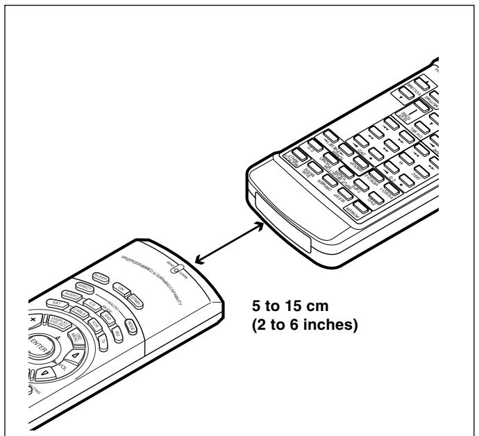
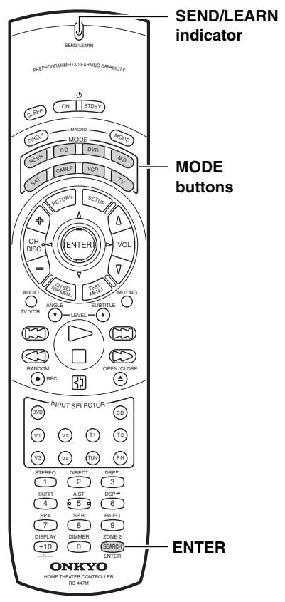
Programming procedure
When programming the commands of another remote controller to the RC-447M remote controller, you must first decide under which MODE button you want the commands to be linked. In general, you will select the MODE button that corresponds to the component you are programming. For example, if you are programming the functions from a remote controller for a compact disc player, you would choose the CD MODE button. Then, by pressing the CD MODE button, the buttons on the RC-447M remote controller will change to the commands you program here to operate the compact disc player.
After programming which MODE button to use, you will then transfer the separate commands from the other remote controller over to the RC-447M remote controller one at a time. Each command is then programmed to a different button on the RC-447M remote controller. Any button is programmable for this step except for the eight MODE buttons (RCVR, CD, DVD, MD, SAT, CABLE, VCR, and TV) and the two MACRO buttons (DIRECT and MODE). Even after the commands have been memorized, keep your old remote controller in a safe place. If for some reason the commands are lost (e.g., when the batteries run down), it will be necessary to memorize them once again.
- Place the remote controller and the remote controller for the other device facing each other at a distance of 5 to 15cm (2 to 6 inches) apart.
- While pressing and holding down the desired MODE button on the remote controller, press the ENTER button and then release both buttons.
When you press and hold down the MODE button, the SEND/LEARN indicator lights. When you press the ENTER button, the lamp turns off. When you release the buttons, the lamp lights again.
- Press and release the button on the remote controller to which you want to transfer the next command.
You may select any button but the ten ones indicated in the figure below. When you press the button, the SEND/LEARN indicator turns off. When you release the button, the indicator lights again.
If you press the wrong button by mistake, press that same button again. The SEND/LEARN indicator flashes twice, and the remote controller exits the programming mode.
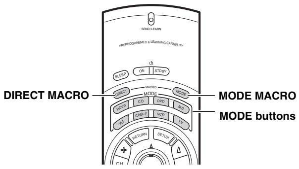
: Buttons that cannot be programmed.
Programming the commands of remote controllers for other devices into the remote controller
- Press and hold down the button (that corresponds to the command you are programming) on the remote controller of the other device until the SEND/LEARN lamp on the remote controller flashes twice.
After flashing twice, the SEND/LEARN indicator will light again. - Repeat Steps 3 and 4 to transfer all the commands you desire from the other remote controller and program them to buttons on the remote controller under the same MODE.
Repeat Steps 2 through 4 to program commands to a different MODE (e.g., when programming from a different remote controller). - Press the MODE button that you pressed in step 2 to complete the programming.
- Operate the newly programmed buttons to make sure the learning function was performed properly.
Notes:
- The remote controller codes for Onkyo compact disc players, cassette tape decks, DVD players, and mini disc recorder have already been programmed into buttons on the remote controller. You may, however, use these buttons to program the codes for other remote controllers. If you wish to restore the Onkyo preset codes after you program new codes, you must first erase the new codes (see page 44).
- The remote controller has 408 memory slots (8 modes × 51 buttons). Some remote controllers may have more commands that can be remembered by the remote controller. In such cases, it will be necessary for you to determine which commands are more important than others.
- If no button is pressed for more than 30 seconds during the programming, or if you perform an invalid operation during programming, the SEND/LEARN indicator flashes three times quickly, and the remote controller exits the programming mode. Resume from Step 2.
- If a failure occurs during programming, the SEND/LEARN indicator flashes three times quickly, and the remote controller exits the programming mode. Resume from Step 3.
- If a failure occurs five times in row during programming, the remote controller exits the programming mode. Resume from Step 3.
- If you try to program beyond the learning capacity of the remote controller, the SEND/LEARN indicator flashes six times quickly, and the remote controller exits the programming mode. Try programming under a different MODE button.
- When you want to program a command to a button to which you have already programmed a command, simply follow the same procedure given and programming for that button will be overwritten.
- The remote controller uses infrared rays to send its commands, as do most other remote controllers. Though most remote controller codes can be memorized by the remote controller, be aware that some remote controllers use a system that is quite different from the remote controller and therefore may not be able to be programmed.
- Some remote controllers have a single button that performs multiple functions (for example, the function may change each time the button is pressed). If this is the case, each function must be programmed to a separate button on the remote controller.
- Once you have transferred the commands from the other remote controller, refer to the instruction manual that came with that product for instructions on how to operate that product.
- Make sure both the remote controller and the other remote controller have new batteries. If either of them has batteries that are low, you may not be able to program the commands of the other remote controller properly into the remote controller.
See page 48 for how to erase the memorized commands from all buttons.
Programming the commands of remote controllers for other devices into the remote controller

Erasing the programmed command from one button
You can only erase memorized commands and not preset ones.
- Press and hold down the desired MODE button for the command, press the ENTER button, and then release both buttons.
When you press the MODE button, the SEND/LEARN indicator lights. When you press the ENTER button, the lamp turns off. When you release the buttons, the lamp lights again.
- Press and release the button for the command you wish to erase.
When you press the button, the SEND/LEARN indicator turns off. When you release the button, the lamp lights again.
- Press and release the same button again.
The SEND/LEARN lamp flashes twice slowly. The memorized command is erased.
Note:
If no button is pressed for more than 30 seconds during the erasing procedure, the SEND/LEARN indicator flashes three times quickly, and the remote controller exits the erasing mode. Resume from Step 1.
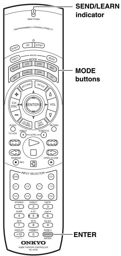
Erasing all the commands programmed under a MODE button
- Press and hold down the desired MODE button, press the ENTER button twice, and then release both buttons.
When you press the MODE button, the SEND/LEARN indicator lights. When you press the ENTER button, the lamp turns off. When you release the buttons, the lamp flashes twice slowly and then lights again.
- Press and release the same MODE button again.
When you release the button, the SEND/LEARN indicator flashes twice slowly. This erases all the commands memorized to the MODE button.
Notes:
- If no button is pressed for more than 30 seconds during the erasing procedure, the SEND/LEARN indicator flashes three times quickly and the remote controller exits the erasing mode. Resume from Step 1.
- If you perform an invalid operation during erasing, the SEND/LEARN indicator flashes three times quickly, and the remote controller exits the erasing mode. Resume from Step 1.
- If many commands have been programmed to the MODE button, then the SEND/LEARN indicator may remain lit for up to 20 seconds during Step 2. This is not a malfunction.
What is a Macro function?
A Macro function enables you to program a series of button operations (up to 16) on the remote controller into a single button. For example, to play a compact disc player connected to the TX-DS595 normally, you must perform the following steps:
- Press the RCVR MODE button.
- Press the ON button.
- Press the CD (INPUT SELECTOR) button.
- Press the CD MODE button.
- Press the playback () button.
By using the macro function, you can perform the above five operations by only pressing two buttons.
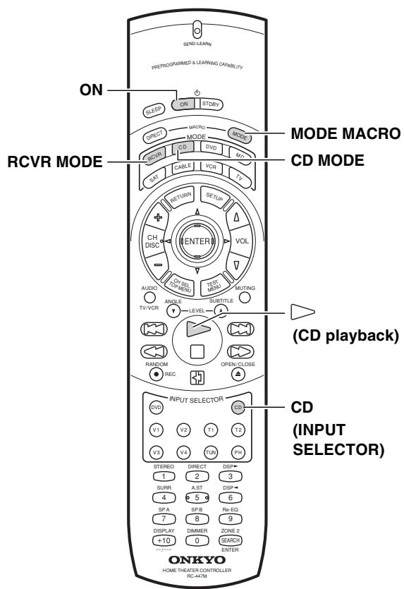
Tips:
- If you erase or change the command of a button programmed in a macro, that operation of that button will no longer work in the macro. In this case, it will be necessary for you to reprogram the macro in order to avoid incorrect operation.
- The codes programmed into a macro will be transmitted at an interval of 0.5 seconds. However, some devices may not be able to complete one operation in 0.5 seconds and may miss the next code. In this case, after pressing one operation button, you can press the same MODE button again before pressing the next operation button to add another 0.5 seconds between the two operations.
Programming a Macro function
You can program a different macro into the MODE MACRO button for each of the eight MODE buttons. The macro is then executed by pressing the appropriate MODE button and then pressing the MODE MACRO button. For example, to program the macro described above into the CD MODE button, perform the steps given below.
- Press and hold down the desired MODE button (in this case, the CD MODE button), press the MODE MACRO button, and then release both buttons.
When you press the CD MODE button, the SEND/LEARN indicator lights and the CD MODE button lights green. When you press the MODE MACRO button, the indicator turns off. When you release the buttons, the indicator flashes and lights again.
- Press the operation buttons you wish to program in order (in this case, press RCVR MODE ON CD (INPUT SELECTOR) CD MODE playback ( ) button).
When you press each button, the SEND/LEARN indicator turns off. When you release the button, the indicator lights.
- Press the MODE MACRO button to complete the programming.
The SEND/LEARN indicator flashes twice slowly.
- Run the macro to check to see if the macro has been properly programmed.
Notes:
- You may program up to 16 button operations into each macro function. If you try to program a 17th operation, it will be ignored, and programming is stopped.
- If no button is pressed for more than 30 seconds during the programming, the SEND/LEARN indicator flashes three times quickly, and the remote controller exits the programming mode. Resume from Step 1.
- If you perform an invalid operation during programming, the SEND/LEARN indicator flashes three times quickly, and the remote controller exits the programming mode. Resume from Step 1.
Running a Macro function
Perform the procedure below to run a macro function that you have programmed into the remote controller. After programming a macro, you should always run it at least once to make sure that it has been programmed properly.
- Point the remote controller at the TX-DS595 and press the CD MODE button.
- Press the MODE MACRO, and verify that the devices operate properly.
It may take a while for the macro to finish transmitting, so be sure to continue pointing the remote controller at the device until the SEND/LEARN indicator turns off.
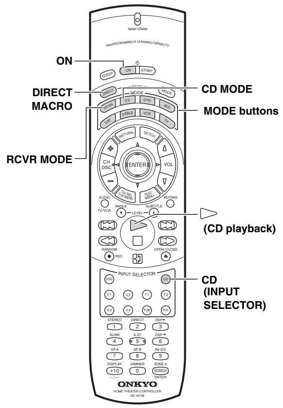
Tips:
- If you erase or change the command of a button programmed in the direct macro, that operation of that button will no longer work in the macro. In this case, it will be necessary for you to reprogram the direct macro in order to avoid incorrect operation.
- The codes programmed into a direct macro will be transmitted at an interval of 0.5 seconds. However, some devices may not be able to complete one operation in 0.5 seconds and may miss the next code. In this case, after pressing one operation button, you can press the same MODE button again before pressing the next operation button to add another 0.5 seconds between the two operations.
Programming the Direct Macro function
With the direct macro function, you can program a series of button operations as a macro into the DIRECT MACRO button so the macro can be executed with just one touch. Note that for the direct macro function, only one macro can be programmed. For example, to program the macro described on the previous page for the DIRECT MACRO button, perform the steps given below.
- Press and hold down any one of the eight MODE buttons, press the DIRECT MACRO button, and then release both buttons.
When you press the MODE button, it lights green and the SEND/LEARN indicator lights. When you press the DIRECT MACRO button, the indicator turns off. When you release the buttons, the indicator flashes briefly and then lights again.
- Press the operation buttons you wish to program in order (in this case, press RCVR MODE ON CD (INPUT SELECTOR) CD MODE playback ( ) button).
When you press each button, the SEND/LEARN indicator turns off. When you release the button, the indicator lights.
- Press the DIRECT MACRO button to complete the procedure.
The SEND/LEARN indicator flashes twice slowly.
- Check to see if the macro has been properly programmed.
Notes:
- You may program up to 16 button operations into the direct macro function. If you try to program a 17th operation, it will be ignored, and programming is stopped.
- If no button is pressed for more than 30 seconds during the programming, the SEND/LEARN indicator flashes three times quickly, and the remote controller exits the programming mode. Resume from Step 1.
- If you perform an invalid operation during programming, the SEND/LEARN indicator flashes three times quickly, and the remote controller exits the programming mode. Resume from Step 1.
Running a Direct Macro function
Perform the procedure below to run a direct macro function that you have programmed into the remote controller. After programming a direct macro, you should always run it at least once to make sure that it has been programmed properly.
1. Point the remote controller at the TX-DS595 and press the DIRECT MACRO button.
It may take a while for the macro to finish transmitting, so be sure to continue pointing the remote controller at the device until the SEND/LEARN indicator turns off.
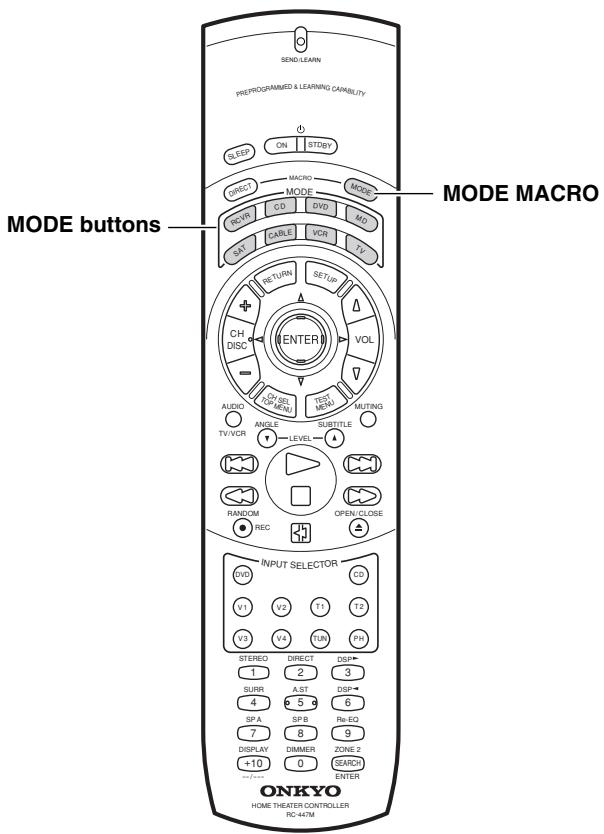
Erasing a macro from the MODE MACRO button
- Press and hold down the desired MODE button, press the MODE MACRO button, and then release both buttons.
When you press the MODE button, it lights green and the SEND/LEARN indicator lights. When you press the MODE MACRO button, the indicator turns off. When you release the buttons, the indicator flashes once.
- Press the MODE MACRO button again.
The SEND/LEARN indicator flashes twice slowly. The macro programmed to the MODE button pressed in Step 1 above is erased.
Notes:
- If no button is pressed for more than 30 seconds during the erasing procedure, the SEND/LEARN indicator flashes three times quickly, and the remote controller exits the erasing mode. Resume from Step 1.
- Be aware that if you press a button other than MODE MACRO button in Step 2, then you will in effect be overwriting the previous macro with a new macro.
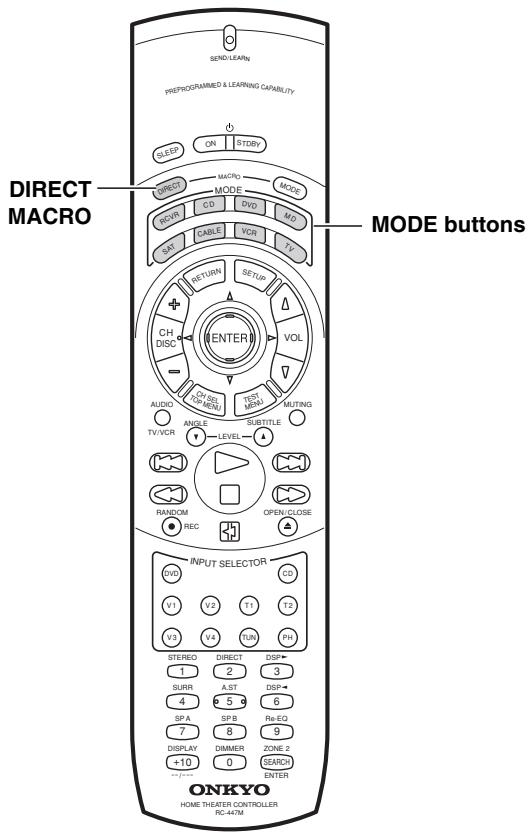
Erasing a direct macro from the DIRECT MACRO button
- Press and hold down any one of the eight MODE buttons, press the DIRECT MACRO button, and then release both buttons.
When you press the MODE button, it lights green and the SEND/LEARN indicator lights. When you press the DIRECT MACRO button, the indicator turns off. When you release the buttons, the indicator flashes once.
- Press the DIRECT MACRO button again.
The SEND/LEARN indicator flashes twice slowly. The macro programmed to the DIRECT MACRO button is erased.
Notes:
- If no button is pressed for more than 30 seconds during the erasing procedure, the SEND/LEARN indicator flashes three times quickly, and the remote controller exits the erasing mode. Resume from Step 1.
- Be aware that if you press a button other than DIRECT MACRO button in Step 2, then you will in effect be overwriting the previous direct macro with a new direct macro.
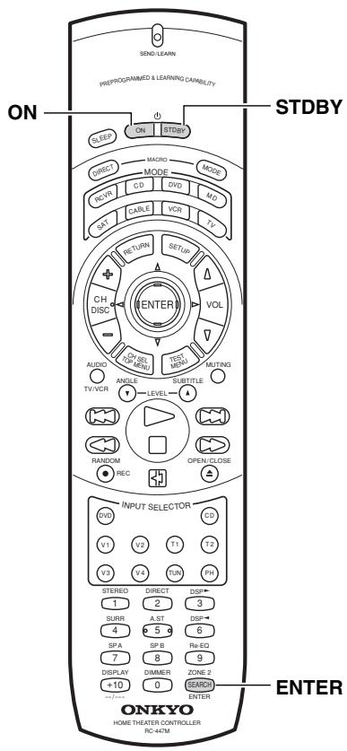
Erasing all commands and macros that have been programmed
This procedure will erase all the commands and macros that you have programmed into the remote controller and return it to its default settings. This operation will not affect the preset settings of the remote controller.
- Open the battery cover and remove the batteries from the remote controller.
- While pressing and holding down the ON and STDBY buttons, re-insert the batteries in their correct orientation, and then release both buttons.
The SEND/LEARN indicator flashes slowly.
- Press the ENTER button.
The SEND/LEARN indicator lights up for about ten seconds and then turns off.
All programmed commands and macros are erased and the remote controller returns to its factory presets.
Notes:
- Proceed to Step 3 immediately after Step 2; otherwise, the batteries will be consumed quickly.
- If you press any button other than the ENTER button in Step 3, nothing will be erased. In this case, resume from Step 1.
Macro mode programming memo:
| MACRO | MODE MACRO ↓ RCVR | MODE MACRO ↓ CD | MODE MACRO ↓ DVD | MODE MACRO ↓ MD | MODE MACRO ↓ SAT | MODE MACRO ↓ CABLE | MODE MACRO ↓ VCR | MODE MACRO ↓ TV | DIRECT MACRO |
| Operation 1 | |||||||||
| Operation 2 | |||||||||
| Operation 3 | |||||||||
| Operation 4 | |||||||||
| Operation 5 | |||||||||
| Operation 6 | |||||||||
| Operation 7 | |||||||||
| Operation 8 | |||||||||
| Operation 9 | |||||||||
| Operation 10 | |||||||||
| Operation 11 | |||||||||
| Operation 12 | |||||||||
| Operation 13 | |||||||||
| Operation 14 | |||||||||
| Operation 15 | |||||||||
| Operation 16 |
AMPLIFIER SECTION
| Continuous Average Power output (FTC) | |
| All channels: | 75 W per channel min. RMS at 8 Ω, 2 channels driven from 20 Hz to 20 kHz with no more than 0.08% total harmonic distortion. 100 W min. RMS at 6 Ω, 2 channels driven from 1 kHz with no more than 0.1% total harmonic distortion. |
| Continuous Power output (DIN) | 110 W at 6 Ω |
| Maximum Power output (EIAJ) | 140 W at 6 Ω |
| Dynamic Power Output (Stereo) | 2 × 210 W at 3 Ω 2 × 155 W at 4 Ω 2 × 90 W at 8 Ω |
| Total Harmonic Distortion: | 0.08% at rated power 0.08% at 1 W output |
| IM Distortion: | 0.08% at rated power 0.08% at 1 W output |
| Damping Factor: | 60 at 8 Ω |
| Input Sensitivity and Impedance | |
| PHONO: | 2.5 mV, 50 kΩ |
| LINE (CD, TAPE, DVD,VIDEO 1, 2, 3): | 200 mV, 50 kΩ |
| MULTICHANNEL INPUT(FRONT L/C/R, SURROUND L/R): | 200 mV, 50 kΩ |
| (SUBWOOFER): | 36 mV, 50 kΩ |
| COAXIAL 1, 2 (DIGITAL): | 0.5 Vp-p, 75 Ω |
| DVD,VIDEO1, 2, 3: | 1 Vp-p, 75 Ω 1 Vp-p, 75 Ω (Y) 0.28 Vp-p, 75 Ω (C) |
| Output Level and Impedance | |
| Rec out (TAPE,VIDEO 1): | 200 mV, 2.2 kΩ |
| Pre out: | 1 V, 470 Ω |
| VIDEO (VIDEO 1, MONITOR OUT): | 1 Vp-p, 75 Ω 1 Vp-p, 75 Ω (Y) 0.28 Vp-p, 75 Ω (C) |
| Phono Overload: | 180 mV RMS at 1 kHz, 0.5% T.H.D. |
| Frequency Response: | 10 Hz to 100 kHz: +1 dB,-3 dB |
| RIAA Deviation: | 20 Hz to 20 kHz: ±0.8 dB |
| Tone Control | |
| Bass: | ±10 dB at 50 Hz |
| Treble: | ±10 dB at 20 kHz |
| Signal-to-Noise Ratio (Stereo) | |
| Phono: | 80 dB (IHFA, 5 mV input) |
| CD/Tape: | 100 dB (IHFA, 0.5 V input) |
| Muting: | -50 dB |
TUNER SECTION
| FM | |
| Tuning Range: | 87.5 to 108.0 MHz (50-kHz steps) |
| Usable Sensitivity | |
| Mono: | 11.2 dBf, 1.0 μV (75 Ω IHF) |
| 0.9 μV (75 Ω DIN) | |
| Stereo: | 17.2 dBf, 2.0 μV (75 Ω IHF) |
| 23 μV (75 Ω DIN) | |
| 50 dB Quieting Sensitivity | |
| Mono: | 17.2 dBf, 2.0 μV (75 Ω) |
| Stereo: | 37.2 dBf, 20 μV (75 Ω) |
| Capture Ratio: | 2.0 dB |
| Image Rejection Ratio: | |
| USA & Canadian models: | 40 dB |
| Other area models: | 85 dB |
| IF Rejection Ratio: | 90 dB |
| Signal-to-Noise Ratio | |
| Mono: | 76 dB |
| Stereo: | 70 dB |
| Alternate Channel Attenuation: | 55 dB |
| Selectivity: | 50 dB (DIN) |
| AM Suppression Ratio: | 50 dB |
| Total Harmonic Distortion | |
| Mono: | 0.2% |
| Stereo: | 0.3% |
| Frequency Response: | 30 Hz to 15 kHz, ±1.0 dB |
| Stereo Separation: | 45 dB at 1 kHz |
| 30 dB at 100 Hz to 10 kHz | |
| AM | |
| Tuning Range | |
| USA & Canadian models: | 530 to 1,710 kHz (10-kHz steps) |
| European & Australian models: | 522 to 1,611 kHz (9-kHz steps) |
| Worldwide models: | 531 to 1,602 kHz (9-kHz steps) |
| 530 to 1,710 kHz (10-kHz steps) | |
| Usable Sensitivity: | 30 μV |
| Image Rejection Ratio: | 40 dB |
| IF Rejection Ratio: | 40 dB |
| Signal-to-Noise Ratio: | 40 dB |
| Total Harmonic Distortion: | 0.7% |
| GENERAL | |
| Power Supply: | AC 120 V, 60 Hz |
| (USA & Canadian models) | |
| AC 230-240 V, 50 Hz | |
| (European & Australian models) | |
| AC 220-230 V, 50/60 Hz | |
| (some Asian models) | |
| AC 220-230 and 120 V switchable, | |
| 50/60 Hz (Worldwide models) | |
| Power Consumption: | 4.7 A |
| 380 W | |
| Dimensions (W × H × D): | 435 × 175 × 431 mm |
| 17-1/8" × 6-7/8" × 16-15/16" | |
| Weight: | 25.4 lbs. (USA & Canadian models) |
| 12.5 kg (Other models) | |
REMOTE CONTROLLER
| Transmitter: | Infrared |
| Signal range: | Approx. 5 meters, 16 ft. |
| Power supply: | Two “AA” batteries (1.5 V × 2) |
Specifications and features are subject to change without notice.
Power supply and voltage vary depending on the area in which the unit is purchased.
If a problem occurs while you are using the remote controller, first try to operate the controls on the front panel of the TX-DS595 to make sure that it is not due to a malfunction (or worn out batteries) in the remote controller.
POWER
Power shuts off immediately after power on.
- Amplifier protection circuitry has been activated.
Remove the power cord from outlet immediately. Contact your Onkyo service center.
No power.
- Power cord is disconnected.
Connect power cord.
- External noise in the affecting the internal microcomputer.
Turn the power button off and then on again or remove the power cord from the outlet and then plug it in again.
- Internal fuse is blown.
Contact your Onkyo Service Center.
Power turns on but no sound.
-MUTING" is displayed.
Press the MUTING button on the remote controller to turn it off.
Bad connections or wiring.
Check connections, speaker cables, etc.
- Amplifier protection circuitry has been activated.
Contact your Onkyo Service Center.
The sound of the playback source is not heard.
- Input selector is not set properly.
Set to correct input source.
- Headphones are connected.
Lower volume and then disconnect headphones.
Pressing the ON button on the remote controller does not turn on the power to the main unit.
- You have not pressed RCVR MODE button.
Press the RCVR MODE button, then press the ON button.
SPEAKERS
No sound from the center speaker, or at very low volume.
- Speaker cable is not connected.
Check the connection between the amplifier and the speaker.
- Listening mode is set to Stereo or Direct.
Set the Listening mode to any mode other than Stereo or Direct. The output to the center speaker may differ depending on the listening mode.
- Center speaker level is set to minimum.
Set the Center speaker level to the appropriate volume (page 20).
- Center speaker is set to "NONE."
Set CENTER to "LARGE" or "SMALL" (page 19).
No sound or very low volume from subwoofer.
- Subwoofer is set to "NO."
Check the speaker setting (page 19).
- Subwoofer speakers output level setting is improper.
Check the output level of the Subwoofer using the test tone (page 19).
Low frequency humming is heard.
- Not properly grounded.
Check outer conductor of input plugs. - Turntable motor is not properly grounded.
Check for proper ground connection. - Audio connection cables on the rear panel are connected incorrectly.
Adjust the placement of the cable to reduce hum.
Howling is heard when the volume is turned up.
- Turntable and speakers are located too close together.
Move them farther apart.
Rough or scratchy sound is heard. High range is not clear.
- The needles of turntable is dirty or worn, or a problem exists with a connected component.
Refer to the instruction of the connected components and check for problem. - Treble control is too high.
Turntrebledown.
FM/AM TUNER
AM stations cannot be received.
- AM loop antenna is not connected.
Connect the included AM loop antenna to the AM antenna terminals.
Buzzing noise on AM stations (particularly noticeable at night or with weak stations).
- Noise from electrical apparatus such as fluorescent lamp.
Move the AM loop antenna to different position.
Set up an outdoor AM antenna.
Noise is heard at high-pitched sounds on AM stations.
- Noise from TV set.
Place the AM loop antenna as far as possible from the TV.
Move unit away from TV set.
Crackling noise on both AM and FM stations.
- Noise caused by fluorescent lamp being turned on and off.
Move antenna as far as possible from the fluorescent lamp. - Noise from automobile ignition.
Install an FM outdoor antenna as far as possible from the road.
Change the position or direction of the outdoor antenna.
The indicators light for stereo reception, but sound is distorted and stereo separation is bad.
- Station is too strong.
Change to FM indoor antenna. - Multiple reflection of the radio waves because of tall buildings or mountains.
Use antenna that has better directivity and select a point where distortion is least.
Indicators for stereo reception flicker and hiss is heard on FM stations.
- Station is too weak.
Install an outdoor FM antenna. - Stereo FM broadcasts cover only about half the distance of an ordinary broadcast.
Change the position or direction of the outdoor antenna.
No preset station is recalled.
- Power cord has been unplugged or the POWER switch has been turned off for a long time.
The memory contents are lost. Store all stations again.
VIDEO and AUDIO
Desired picture does not appear.
- Improper connection.
Check the connection again. Insert the plugs and connectors completely.
Picture and sound do not match.
- Improper connection.
Check connections.
No sound, or sound of the selected source is not heard.
Audio Setup of Input Setup settings are incorrect.
Check settings.
No picture appears on the TV screen (or monitor).
- TV (or monitor) is not set to receive the output signals from the receiver.
Set the TV (or monitor) to the receiver input.
Video cable is not connected securely.
Check connections.
- The video input and output connections are incorrect.
If your video component is connected to SVIDEO IN, then your television monitor must be connected to SVIDEO OUT. If your video component is connected toVIDEO IN, then your television monitor must be connected toVIDEO OUT. Be aware that the signal input to SVIDEO IN is not output fromVIDEO OUT and the signal input toVIDEO IN is not output from SVIDEO OUT.
REMOTE CONTROLLER
Front panel controls function but remote controller controls do not.
- No batteries in remote controller. Insert batteries.
- Batteries have worn out. Replace batteries.
- Remote controller is not pointed at the remote sensor of the TX-DS595.
Point the remote controller at the remote sensor of the TX-DS595.
Remote controller is too far from the TX-DS595.
Operate the remote controller within 5 meters (16 feet).
- Remote controller is functioning in a different mode
Press the RCVR MODE button.
OTHER
LATE NIGHT function cannot be used.
- Playback source is not Dolby Digital encoded.
Check that the DOLBY DIGITAL indicator lights up on the display.
Re-EQ function cannot be used.
- Re-EQ is only enabled for Analog/PCM sources and Dolby Digital surround.
See page 9.
Multichannel audio is not output.
- To listen to multichannel audio, "YES" must be selected in the Multichannel in the Audio Setup of the Input Setup. Also, it is necessary to select Multichannel with the AUDIO SELECTOR button.
Check that the component is connected to the MULTI CHANNEL INPUT port and check the setup settings.
If one of the messages shown below appears
"NOT AVAILABLE WITH HEADPHONES USE"
The operation is not allowed because headphones are plugged into the TX-DS595.
"NOT AVAILABLE WITH MULTICHANNEL USE"
The operation is not allowed because the selected input source is set for multichannel input.
"NOT AVAILABLE IN THIS SP CONFIG"
The operation is not allowed by the current speaker configuration.
"NOT AVAILABLE IN THIS LISTENING MODE"
This operation cannot be performed in this listening mode.
"NOT AVAILABLE WITH THIS SIGNAL"
This operation cannot be performed with this input signal.
Also refer to the respective instruction manuals of the compact disc player, DVD player, video cassette recorder, TV monitor, etc., that compose your entertainment system.
The TX-DS595 contains an internal microcomputer that performs high-level operations. However, on extremely rare occasions, noise or interference from an external source or static electricity may cause faulty operation. If this occurs, unplug the power cord from the wall outlet, wait five or more seconds, and then plug it back in. This should correct the situation.
- To reset the surround mode and other settings to the factory default settings, hold down the PRESET MEMORY button with the TX-DS595 turned on and then press the STANDBY/ON button. "CLEAR" appears in the front display and the TX-DS595 enters the standby state.
ONKYO CORPORATION
Sales & Product Planning Div. : 2-1, Nisshin-cho, Neyagawa-shi, OSAKA 572-8540, JAPAN
Tel: 072-831-8111 Fax: 072-833-5222
18 Park Way, Upper Saddle River, N.J. 07458, U.S.A.
Tel: 201-785-2600 Fax: 201-785-2650 E-mail: onkyo@onkyousa.com
ONKYO EUROPE ELECTRONICS GmbH
Industriestrasse 20, 82110 Germering, GERMANY
Tel: 089-849-320 Fax: 089-849-3265 E-mail: info@onkyo.de
ONKYO CHINA LIMITED
Units 2102-2107, Metroplaza Tower I, 223 Hing Fong Road, Kwai Chung,
N.T., HONG KONG Tel: 852-2429-3118 Fax: 852-2428-9039