USER MANUAL 1U24GS1ERA HAIER
Indoor/Outdoor Unit Installion Drawings 1
Safety Precautions 2
Read Before Installation 6
Installation Procedure 9
Outdoor Unit Troubleshooting 14
English
Espanol
Contidente
CE
All the products are in conformity with the following European provision:
- Low Voltage Directive 73/23/EEC
- Low Voltage Directive 2006/95/EC
-Electromagnetic CompatibilityY 89/336/EEC
-Electromagnetic CompatibilityY 2004/108/EC
ROHS
The products are fulfilled with the requirements in the directive 2002/95/EEC of the European parliament and of council on the Restriction of the use of Certain Hazardous Substances in Electrical and Electronic Equipment (EU RoHS Directive)
WEEE
In accordance with the directive 2002/96/CE of the European parliament, herewith we inform the consumer about the disposal requirements of the electrical and electronic products.
DISPOSAL REQUIREMENTS:
Your air conditioning product is marked with this symbol. This means that electrical and electronic products shall not be mixed with unsorted household waste. Do not try to dismantle the system yourself : the dismantling of the air
conditioning system, treatment of the refrigerant, of oil and of other part must be done by a qualified installer in accordance with relevant local and national legislation. Air conditioners must be treated at a specialized treatment facility for reuse, recycling and recovery. By ensuring this product is disposed of correctly, you will help to prevent potential negative consequences for the environment and human health. Please contact the installer or local authority for more information. Battery must be removed from the remote controller and disposed of separately in accordance with relevant local and national legislation.
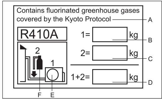
This product contains fluorinated greenhouse gases covered by the Kyoto Protocol. Do not vent into the atmosphere.
Refrigerant type:R410A
GWP* value:1975
GWP=global warming potential
Please fill in with indelible ink,
The filled out label must be adhered in the proximity of the product charging port (e.g. onto the inside of the stop value cover).
A contains fluorinated greenhouse gases covered by the Kyoto Protocol
B factory refrigerant charge of the product: see unit name plate
C additional refrigerant amount charged in the field
D total refrigerant charge
E outdoor unit
F refrigerant cylinder and manifold for charging
The models adopt HFC free refrigerant R410A.
For installation of the indoor units, refer to the installation manual which was provided with the units.
(The diagram shows a wall-mounted indoor unit.)
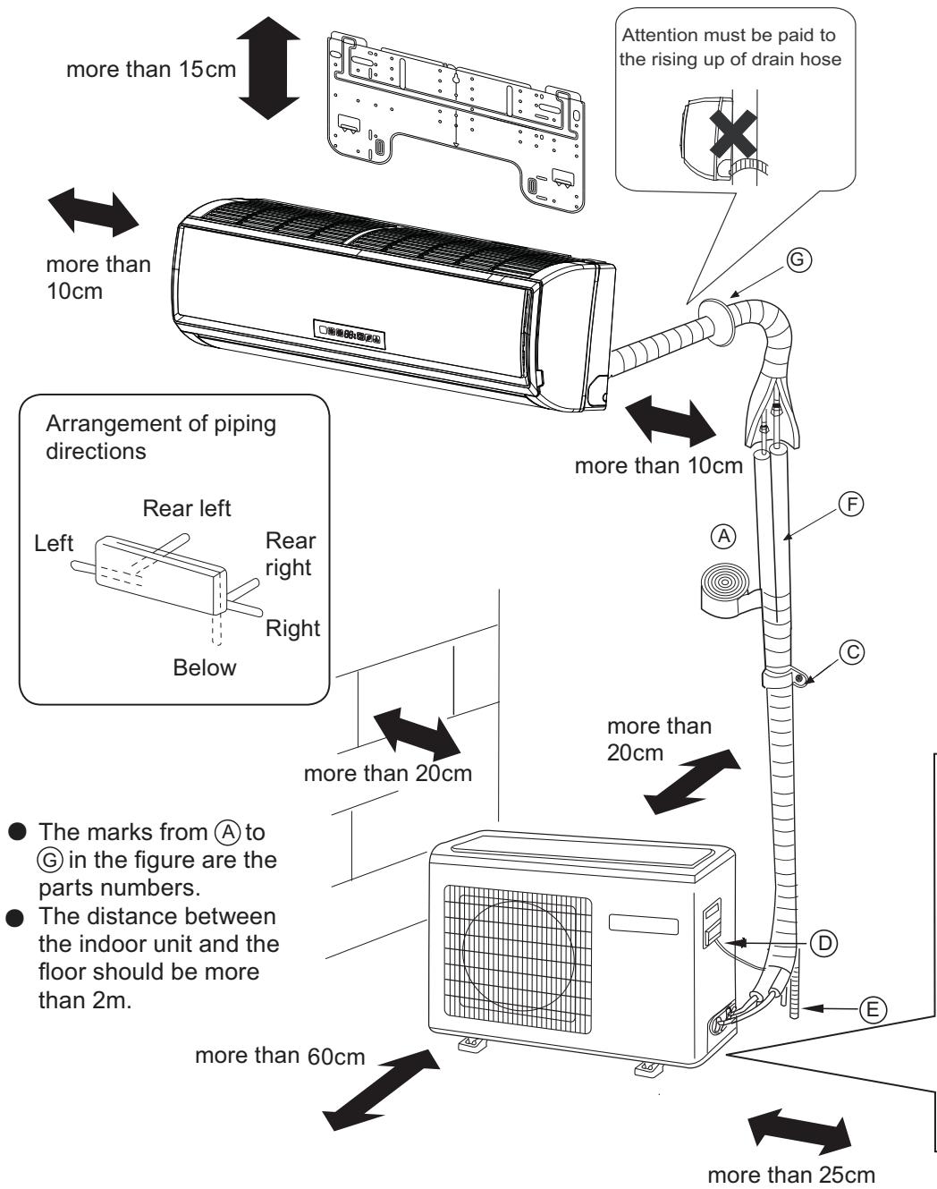
Optional parts for piping
A Non-adhesive tape
(B) Adhesive tape
C Saddle (L.S) with screws
D Connecting electric cable for indoor and outdoor
E Drain hose
Heating insulating material
⑥ Piping hole cover
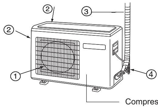
① AIR OUTLET
② AIR INLET
③ CONNECTING PIPING AND ELECTRICAL WIRING
④ DRAIN HOSE
Compressor(Inside of Unit)
- The above indoor and outdoor units' picture is just for your reference.
Please be subject to the actual product purchased.
Carefully read the following information in order to operate the air conditioner correctly.
Below are listed three kinds of Safety Precautions and Suggestions.
WARNING Incorrect operations may result in severe consequences of death or serious injuries.
CAUTION Incorrect operations may result in injuries or machine damages; in some cases may cause serious consequences.
INSTRUCTIONS: These information can ensure the correct operation of the machine.
Symbols used in the illustrations
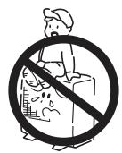
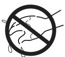
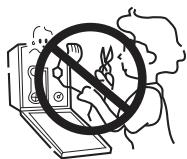
:Indicates an action that must be avoided.
:Indicates that important instructions must be followed.
Indicates a part which must be grounded.
: Beware of electric shock (This symbol is displayed on the main unit label.)
After reading this handbook, hand it over to those who will be using the unit.
The user of the unit should keep this manual at hand and make it available to those who will be performing repairs or relocating the unit. Also, make it available to the new user when the user changes hands.
Be sure to conform with the following important Safety Precautions.
WARNING
- If any abnormal phenomena is found (e.g. smell of firing), please cut off the power supply immediately, and contact the dealer to find out the handling method.
In such case, to continue using the conditioner will damage the conditioner, and may cause electrical shock or fire hazard.
- After a long time use of air-conditioner the base should be checked for any damages.
If the damaged base is not repaired, the unit may fall down and cause accidents.
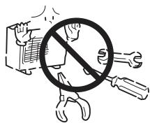
- Don't dismantle the outlet of the outdoor unit. The exposure of fan is very dangerous which may harm human beings.
- When need maintenance and repairment, call dealer to handle it. Incorrect maintenance and repairment may cause water leak, electrical shock and fire hazard.
WARNING
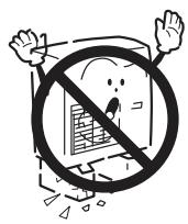
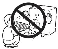
- No goods or nobody is permitted to placed on or stand on outdoor unit. The falling of goods and people may cause accidents.
- Don't operate the air-conditioner with damp hands. Otherwise it will be shocked.
- Only use correctly-typed fuse.
May not use wire or any other materials replacing fuse, otherwise it may cause faults or fire accidents.
- Use discharge pipe correctly to ensure efficient discharge. Incorrect pipe use may cause water leaking.
- Installed electrical-leaking circuit breaker. It easily cause electrical shock without circuit breaker.
- Air-conditioner can't be installed in the environment with inflammable gases because the inflammable gases near air-conditioner may cause fire hazard. Please let the dealer be responsible for installing the conditioner. Incorrect installation may cause water leak, electrical shock and fire hazard.
- Call the dealer to take measures to prevent the refrigerant from leaking. If conditioner is installed in a small room, be sure to take every measure in order to prevent suffocation accident even in case of refrigerant leakage.
-
When conditioner is installed or reinstalled, the dealer should be responsible for them. Incorrect installation may cause water leaking, electrical shock and fire hazard.
-
Connect earthing wire.
-
Earthing wire should not be connected to the gas pipe, water pipe, lightning rod or phone line, incorrect earthing may cause shock.

Earthing
| WARNING |
| ·No goods or nobody is permitted to placed on or stand on outdoor unit.The falling of goods and people may cause accidents.
·Don't operate the air-conditioner with damp hands. Otherwise it will be shocked.
·Only use correctly-typed fuse.
May not use wire or any other materials replacing fuse, otherwise it may cause faults or fire accidents.
·Use discharge pipe correctly to ensure efficient discharge.
Incorrect pipe use may cause water leaking.
·Installed electrical-leaking circuit breaker.
It easily cause electrical shock without circuit breaker. | ·Air-conditioner can't be installed in the environment with inflammable gases because the inflammable gases near air-conditioner may cause fire hazard.
Please let the dealer be responsible for installing the conditioner. Incorrect installation may cause water leak, electrical shock and fire hazard.
·Call the dealer to take measures to prevent the refrigerant from leaking.
If conditioner is installed in a small room, be sure to take every measure in order to prevent suffocation accident even in case of refrigerant leakage.
·When conditioner is installed or reinstalled, the dealer should be responsible for them.
Incorrect installation may cause water leaking, electrical shock and fire hazard.
·Connect earthing wire.
Earthing wire should not be connected to the gas pipe, water pipe, lightning rod or phone line, incorrect earthing may cause shock. |
| ▲WARNING |
| ·Have the unit professionally installed.
Improper installation by an unqualified person may result in water leak, electric shock, or fire.
·Place the unit on a stable, level surface that withstands the weight of the unit to prevent the unit from tipping over or falling causing injury as a result.
·Only use specified cables for wiring. Securely connect each cable, and make sure that the cables are not straining the terminals.
Cables not connected securely and properly may generate heat and cause fire.
·Take necessary safety measures against typhoons and earthquakes to prevent the unit from falling over.
·Do not make any changes or modifications to the unit. In case of problems, consult the dealer.
If repairs are not made properly, the unit may leak water and present a risk of electric shock, or it may produce smoke or cause fire. | ·Be sure to carefully follow each step in this handbook when installing the unit.
Improper installation may result in water leak, electric shock, smoke or fire.
·Have all electrical work performed by a licensed electrician according to the local regulations and the instructions given in this manual. Secure a circuit designated exclusively to the unit.
Improper installation or a lack of circuit capacity may cause the unit to malfunction or present a risk of electric shock, smoke, and fire.
·Securely attach the terminal cover panel) on the unit.
If installed improperly, dust and/or water may enter the unit and present a risk of electric shock, smoke or fire.
·Only use refrigerant R410A as indicated on the unit when installing or relocating the unit.
The use of any other refrigerant or an introduction of air into the unit circuit may cause the unit to run an abnormal cycle and abnormal cycle and cause the unit to burst. |
| ▲WARNING |
| ·Do not touch the fins on the heat exchanger with bare hands, for they are sharp and dangerous.
·In the event of a refrigerant gas leak, provide adequate ventilation to the room.
If leaked refrigerant gas is exposed to a heat source, noxious gases may form.
·With All-Fresh type air conditioners, outdoor air may be directly blown into the room upon thermo off. Take this into consideration when installing the unit.
Direct exposure to outdoor air may present a health hazard, and it may also cause food items to deteriorate.
·Do not try to defeat the safety features of the devices, and do not change the settings.
Defeating the safety features on the unit such as the pressure switch and temperature switch or using parts other than the dealer or specialist may result in fire or explosion. | ·When installing the unit in a small room, safeguard against hypoxia that results from leaked refrigerant reaching the threshold level.
Consult the dealer for necessary measures to take.
·When relocating the air conditioner, consult the dealer or a specialist.
Improper installation may result in water leak, electric shock, or fire.
·After completing the service work, check for a refrigerant gas leak.
If leaked gas refrigerant is exposed to a heat source such as fan heater, stove, and electric grill, noxious gases may form.
·Only use specified parts.
Have the unit professionally installed. Improper installation may cause water leak, electric shock, smoke, or fire. |
Precautions for Handling Units for Use with R410A
| △Caution |
| Do not use the existing refrigerant piping
·The old refrigerant and refrigerator oil in the existing piping contain a large amount of chlorine, which will cause the refrigerator oil in the new unit to deteriorate.
·R410A is a high-pressure refrigerant, and the use of the existing piping may result in bursting. | Use a vacuum pump with a reverse-flow check valve.
·If other types of valves are used, the vacuum pump oil will flow back into the refrigerant cycle and cause the refrigerator oil to deteriorate.
Do not use the following tools that have been used with the conventional refrigerants. Prepare tools that are for exclusive use with R410A.
(Gauge manifold, charging hose, gas leak detector, reverse-flow check valve, refrigerant charge base, vacuum gauge, and refrigerant recovery equipment.)
·If refrigerant and/or refrigerant oil left on these tools are mixed in with R410, or if water is mixed with R410A, it will cause the refrigerant to deteriorate.
·Since R410A does not contain chlorine, gas-leak detectors for conventional refrigerators will not work. |
| Keep the inner and outer surfaces of the pipes clean and free of contaminants such as sulfur, oxides, dust/dirt shaving particles,oils,and moisture.
·Contaminants inside the refrigerant piping will cause the refrigerant oil to deteriorate. |
| △Caution |
| Store the piping to be used during installation indoors, and keep both ends of the piping sealed until immediately before brazing.(keep elbows and other joints wrapped in plastic.)
•If dust, dirt, or water enters the refrigerant cycle, it may cause the oil in the unit to deteriorate or may cause the compressor to malfunction.
Use a small amount of ester oil, ether oil, or alkylbenzene to coat flares and flange connections.
•A large amount of mineral oil will cause the refrigerating machine oil to deteriorate.
Use liquid refrigerant to charge the system.
•Charge the unit with gas refrigerant will cause the refrigerant in the cylinder to change its composition and will lead to a drop in performance | Do not use a charging cylinder.
•The use of charging cylinder will change the composition of the refrigerant and lead to power loss.
Exercise special care when handling the tools.
•An introduction of foreign objects such as dust, dirt or water into the refrigerant cycle will cause the refrigerating machine oil to deteriorate.
Only use R410A refrigerant.
•The use of refrigerants containing chlorine(i.e. R22) will cause the refrigerant to deteriorate. |
Before Installing the Unit
| △Caution |
| Do not install the unit in a place where there is a possibility of flammable gas leak.
·Leaked gas accumulated around the unit may start a fire.
Do not use the unit to preserve food, animals, plants, artifacts, or for other special purposes.
·The unit is not designed to provide adequate conditions to preserve the quality of these items.
Do not use the unit in an unusual environment
·The use of the unit in the presence of a large amount of oil, steam, acid, alkaline solvents or special types of sprays may lead to a remarkable drop in performance and/or malfunction and presents a risk of electric shock, smoke, or fire.
·The presence of organic solvents, corroded gas (such as ammonia,sulfur compounds,and acid may cause gas or water leak.) | When installing the unit in a hospital, take necessary measures against noise.
·High-frequency medical equipment may interfere with the normal operation of the air conditioning unit or the air conditioning unit may interfere with the normal operation of the medical equipment
Do not place the unit on or over things that may not get wet.
·When humidity level exceeds 80% or when the drainage system is clogged, indoor units may drip water.
·Installation of a centralized drainage system for the outdoor unit may also need to be considered to prevent water drips from the outdoor units. |
| △Caution |
| Ground the unit.
·Do not connect the grounding on the unit to gas pipes, water pipes, lightning rods, or the grounding terminals of telephones. Improper grounding presents a risk of electric shock, smoke, fire, or the noise caused by improper grounding may cause the unit to malfunction.
Make sure the wires are not subject to tension.
·If the wires are too taut, they may break or generate heat and/or smoke and cause fire.
Install a breaker for current leakage at the power source to avoid the risk of electric shock.
·Without a breaker for current leakage, there is a risk of electric shock, smoke or fire.
Use breakers and fuses (electrical current breaker, remote switch<switch+Type-B fuse>, molded case circuit breaker) with a proper current capacity.
·The use of large-capacity fuses, steel wire, or copper wire may damage the unit or cause smoke or fire. | Do not spray water on the air conditioners or immerse the air conditioners in water.
·Water on the unit presents a risk of electric shock.
Periodically check the platform on which is placed for damage to prevent the unit from falling.
·If the unit is left on a damaged plarform, it may topple over, causing injury.
When installing draining pipes, follow the instructions in the manual, and make sure that they properly drain water so as to avoid dew condensation.
·If not installed properly, they may cause water leaks and damage the furnishings.
Properly dispose of the packing materials.
·Things such as nails may be included in the package.
Disposition of them properly to prevent injury.
·Plastic bags present a choking hazard to children. Tear up the plastic bags before disposing of them to prevent accidents. |
Before the Test Run
| △Caution |
| Do not operate switches with wet hands to avoid electric. | Do not turn off the power immediately after stopping the unit.
•Allow for at least five minutes before turning off the unit, otherwise the unit may leak water or experience other problems. |
| Do not touch the refrigerant pipes with bare hands during and immediately after operation.
•Depending on the state of the refrigerant in the system, certain parts of the unit such as the pipes and compressor may become very cold or hot and may subject the person to frost bites or burning. |
| Do not operated the unit without panels and safety guards in their proper places.
•They are there to keep the users from injury from accidentally touching rotating, high-tempreture or high-voltage parts. | Do not operate the unit without air filters.
•Dust particles in the air may clog the system and cause malfunction. |
Items to Be Checked
(1). Verify the type of refrigerant used by the unit to be serviced. Refrigerant Type: R410A
(2). Check the symptom exhibited by the unit to be serviced. Look in this service handbook for symptoms relating to the refrigerant cycle.
(3). Be sure to carefully read the safety precautions at the beginning of this document.
(4). If there is a gas leak or if the remaining refrigerant is exposed to an open flame, a noxious gas hydrofluoric acid may form. Keep workplace well ventilated.
CAUTION
- Install new pipes immediately after removing old ones to keep moisture out of the refrigerant circuit.
- Chloride in some types of refrigerants such as R22 will cause the refrigerating machine oil to deteriorate.
Prepare the following tools and materials necessary for installing and servicing the unit.
Necessary tools for use with R410A(Adaptability of tools that are for use with R22 and R407C).
- To be used exclusively with R410A ( Not to be used if used with R22 or R407C )
| Tools/Materials | Use | Notes |
| Gauge Manifold | Evacuating,refrigerant charging | 5.09MPa on the High-pressure side. |
| Charging Hose | Evacuating, refrigerant charging | Hose diameter larger than the conventional ones. |
| Refrigerant Recovery Equipment | Refrigerant recovery | |
| Refrigerant Cylinder | Refrigerant charging | Write down the refrigerant type. Pink in color at the top of the cylinder. |
| Refrigerant Cylinder Charging Port | Refrigerant charging | Hose diameter larger than the conventional ones. |
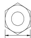
| Flare Nut | Connecting the unit to piping | Use Type-2 Flare nuts. |
| Tools/Materials | Use | Notes |
| Gas leak detector | Detection of gas leaks | The ones for HFC type refrigerant may be used. |
| Vacuum Pump | Vacuum drying | May be used if a reverse flow check adaptor is attached. |
| Flare Tool | Flare machining of piping | Chages have been made in the flare machining dimension.Refer to the next page. |
| Refrigerant Recovery Equipment | Recovery of refrigerant | May be used if designed for use with R410A. |
| Tools/Materials | Use | Notes |
| Vacuum Pump with a Check Valve | Vacuum drying | |
| Bender | Bending pipes | |
| Torque Wrench | Tightening flare nuts | Only φ12.70 (1/2") and φ15.88(5/8") have a larger flare machining dimension. |
| Pipe Cutter | Cutting pipes | |
| Welder and Nitrogen Cylinder | Welding pipes | |
| Refrigerant Charging Meter | Refrigerant charging | |
| Vacuum Gauze | Checking vacuum degree | |
| Tools/Materials | Use | Notes |
| Charging Cylinder | Refrigerant Charging | Must not be used with R410-type units. |
Tools for R410A must be handled with special care, and keep moisture and dust from entering the cycle.
Piping Materials
Types of Copper Pipes (Reference)
| Maximum Operation Pressure | Applicable Refrigerants |
| 3.4MPa | R22, R407C |
| 4.15MPa | R410A |
- Use pipes that meet the local standards.
Piping Materials/Radial Thickness
Use pipes made of phosphorus deoxidized copper.
Since the operation pressure of the units that use R410A is higher than that of the units for use with R22, use pipes with at least the radial thickness specified in the chart below. (Pipes with a radial thickness of 0.7mm or less may not be used.)
| Size(mm) | Size(inch) | Radial Thickness(mm) | Type |
| Φ 6.35 | 1/4" | 0.8t | Type-O pipes |
| Φ 9.52 | 3/8" | 0.8t |
| Φ 12.7 | 1/2" | 0.8t |
| Φ 15.88 | 5/8" | 1.0t |
| Φ 19.05 | 3/4" | 1.0t | Type-1/2H or Hpipes |
- Although it was possible to use type-O for pipes with a size of up to 19.05(3/4^) with conventional refrigerants, use type-1/2H pipes for units that use R410A.(Type-O pipes may be used if the pipe size is 19.05 and the radial thickness is 1.2t. )
- The table shows the standards in Japan. Using this table as a reference, choose pipes that meet the local standards.
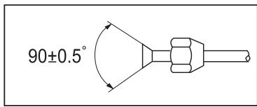
Flare Machining (type-O and OL only)
The flare machining dimensions for units that use R410A is larger than those for units that use R22 in order to increase air tightness.
Flare Machining Dimension(mm)
| External dimension of pipes | Size | Dimension A |
| R410A | R22 |
| Φ6.35 | 1/4" | 9.1 | 9.0 |
| Φ9.52 | 3/8" | 13.2 | 13.0 |
| Φ12.7 | 1/2" | 16.6 | 16.2 |
| Φ15.88 | 5/8" | 19.7 | 19.4 |
| Φ19.05 | 3/4" | 24.0 | 23.3 |
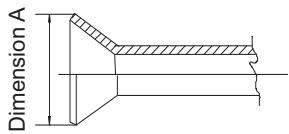
If a clutch type flare tool is used to machine flares on units that use R410A, make the protruding part of the pipe between 1.0 and 1.5mm . Copper pipe gauge for adjusting the length of pipe protrusion is useful.
Flare Nut
Type-2 flare nuts instead of type-1 nuts are used to increase the strength. The size of some of the flare nuts have also been changed.
Flare nut dimension(mm)
| External dimension of pipes | Size | Dimension B |
| R410A(Type2) | R22(Type1) |
| Φ6.35 | 1/4" | 17.0 | 17.0 |
| Φ9.52 | 3/8" | 22.0 | 22.0 |
| Φ12.7 | 1/2" | 26.0 | 24.0 |
| Φ15.88 | 5/8" | 29.0 | 27.0 |
| Φ19.05 | 3/4" | 36.0 | 36.0 |
Dimension B
- The table shows the standards in Japan. Using this table as a reference, choose pipes that meet the local standards.
Air Tightness Test
No changes from the conventional method. Note that a refrigerant leakage detector for R22 or R407C cannot detect R410A leakage.
Halide torch
R22 or R407C leakage detector
Items to be strictly observed :
- Pressurize the equipment with nitrogen up to the design pressure and then judge the equipment's air tightness, taking temperature variations into account.
- When investigating leakage locations using a refrigerant, be sure to use R410A.
- Ensure that R410A is in a liquid state when charging.
Reasons:
- Use of oxygen as the pressurized gas may cause an explosion.
- Charging with R410A gas will lead the composition of the remaining refrigerant in the cylinder to change and then this refrigerant can not be used.
Vacuuming
1. Vacuum pump with check valve
A vacuum pump with a check valve is required to prevent the vacuum pump oil from flowing back into the refrigerant circuit when the vacuum pump power is turned off (power failure). It is also possible to attach a check valve to the actual vacuum pump afterwards.
2.Standard degree of vacuum for the vacuum pump
Use a pump which reaches 65Pa or below after 5 minutes of operation.
In addition, be sure to use a vacuum pump that has been properly maintained and oiled using the specified oil. If the vacuum pump is not properly maintained, the degree of vacuum may be too low.
3. Required accuracy of the vacuum gauge
Use a vacuum gauge that can measure up to 650Pa . Do not use a general gauge manifold since it cannot measure a vacuum of 650Pa .
4.Evacuating time
Evacuate the equipment for 1 hour after 650Pa has been reached.
After evacuating, leave the equipment for 1 hour and make sure the that vacuum is not lost.
5.Operating procedure when the vacuum pump is stopped
In order to prevent a backflow of the vacuum pump oil, open the relief valve on the vacuum pump side or loosen the charge hose to draw in air before stopping operation. The same operating procedure should be used when using a vacuum pump with a check valve.
Charging Refrigerant
R410A must be in a liquid state when charging.
Reasons:
R410A is a pseudo-azeotropic refrigerant (boiling point R32 = -52^ , R125 = -49^ ) and can roughly be handled in the same way as R22; however, be sure to fill the refrigerant from the liquid side, for doing so from the gas side will somewhat change the composition of the refrigerant in the cylinder.
Note
- In the case of a cylinder with a syphon, liquid R410A is charged without turning the cylinder up side down. Check the type of cylinder before charging.
Remedies to be taken in case of a refrigerant leak
When refrigerant leaks, additional refrigerant may be charged. (Add the refrigerant from the liquid side)
Characteristics of the Conventional and the New Refrigerants
- Because R410A is a simulated azeotropic refrigerant, it can be handled in almost the same manner as a single refrigerant such as R22. However, if the refrigerant is removed in the vapor phase, the composition of the refrigerant in the cylinder will somewhat change.
- Remove the refrigerant in the liquid phase. Additional refrigerant may be added in case of a refrigerant leak.
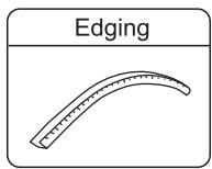
1. Accessories
"Edging" for protection of electrical wires from an opening edge.
2. Selection of the place of installation
Select the place of installation satisfying the following conditions and, at the same time, obtain a consent from the client or user.
- Place where air circulates.
- Place free from heat radiation from other heat sources.
- Place where drain water may be discharged.
- Place where noise and hot air may not disturb the neighborhood.
- Place where there is not heavy snowfall in the winter time.
- Place where obstacles do not exist near the air inlet and air outlet.
- Place where the air outlet may not be exposed to a strong wind.
- Place surrounded at four sides are not suitable for installation. A 1m or more of overhead space is needed for the unit.
- Avoid mounting guide-louvers to the place where short-circuit is a possibility.
- When installing several units, secure sufficient suction space to avoid short circuiting.
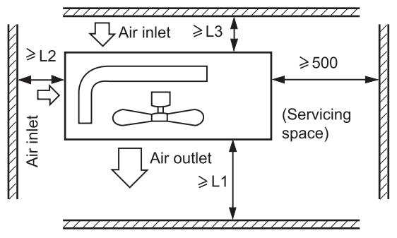
Open space requirement around the unit
Distance
| L1 | open | open | 500 mm |
| L2 | 300 mm | 300 mm | open |
| L3 | 150 mm | 300 mm | 150 mm |
Note :
(1) Fix the parts with screws.
(2) Don't intake the strong wind directly to the outlet air-flow hole.
(3) A one meter distance should be kept from the unit top.
(4) Don't block the surroundings of the unit with sundries.
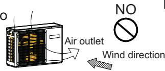
(5) If the outdoor unit is installed in a place that is exposed to the wind, install the unit so that the outlet grid is NOT pointing in the direction of the wind.
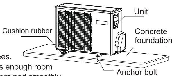
3. Installation of outdoor unit
Fix the unit on the foundation in a proper way according to the condition of the installation place, referring to the following information.
- Give enough room for the concrete foundation to fix by anchor bolts.
- Place the concrete foundation deep enough.
- Install the unit so that the angle of inclination must be less than 3 degrees.
- Forbidden to place the unit on the ground directly. Please confirm there is enough room near the drainage hole on bottom plate, which will ensure the water be drained smoothly.
4.Installation dimension(Unit:mm)
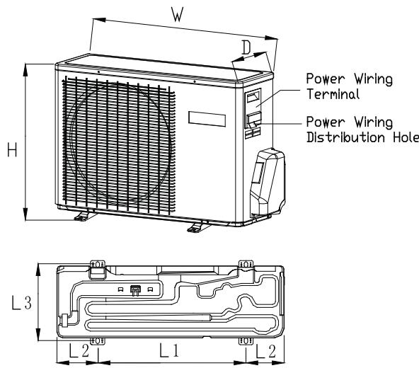
| Model | W | D | H | L1 | L2 | L3 |
| 1U07BS1ERA | 780 | 245 | 540 | 500 | 140 | 256 |
| 1U09BS1ERA | 780 | 245 | 540 | 500 | 140 | 256 |
| 1U12BS1ERA | 780 | 245 | 540 | 500 | 140 | 256 |
| 1U18FS1ERA | 810 | 288 | 688 | 583 | 113.5 | 319.5 |
| 1U24GS1ERA | 860 | 308 | 730 | 633 | 113.5 | 340 |
1. Piping size
| 1U07BS1ERA 1U09BS1ERA
1U12BS1ERA | Liquid pipe | Φ 6.35x0.8mm |
| Gas pipe | Φ 9.52x0.8mm |
| 1U18FS1ERA | Liquid pipe | Φ 6.35x0.8mm |
| Gas pipe | Φ 12.7x0.8mm |
| 1U24GS1ERA | Liquid pipe | Φ 9.52x0.8mm |
| Gas pipe | Φ 15.88x1.0mm |
- Install the removed flare nuts to the pipes to be connected, then flare the pipes.
2. Connection of pipes
- To bend a pipe, give the roundness as large as possible not to crush the pipe, and the bending radius should be 30 to 40 ~mm or longer.
- Connecting the pipe of gas side first makes working easier.
- The connection pipe is specialized for R410A.
Forced fastening without careful centering may damage the threads and cause a leakage of gas.
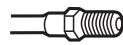
Half union
Flare nut
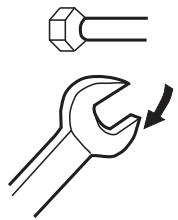
Spanner
Torque wrench
| Pipe Diameter(ø) | Fastening torque |
| Liquid side6.35mm(1/4") | 18N.m |
| Liquid/Gas side9.52mm(3/8") | 42 N.m |
| Gas side 12.7mm(1/2") | 55N.m |
| Gas side 15.88mm(5/8") | 60 N.m |
Be careful that matters, such as wastes of sands, water, etc. shall not enter the pipe.
CAUTION
The standard pipe length is C_m . If it is over D_m , the function of the unit will be affected. If the pipe has to be lengthened, the refrigerant should be charged, according to E g/m . But the charge of refrigerant must be conducted by professional air conditioner engineer. Before adding additional refrigerant, perform air purging from the refrigerant pipes and indoor unit using a vacuum pump, then charge additional refrigerant.
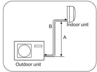
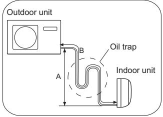
Max.Elevation: Amax
In case the elevation A is more than 5m oil trap should be installed every 5~7
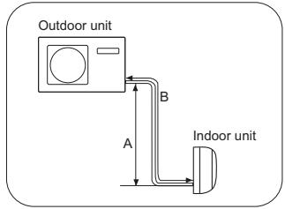
Max. Length: Bmax
- In case the pipe length B is more than Dm, the refrigerant should be charged, according to E g/m.
| Outdoor Unit | Amax | Bmax | C | D | E |
| 1U07BS1ERA | 10 | 15 | 5 | 7 | 20 |
| 1U09BS1ERA | 10 | 15 | 5 | 7 | 20 |
| 1U12BS1ERA | 10 | 15 | 5 | 7 | 20 |
| 1U18FS1ERA | 15 | 25 | 5 | 7 | 20 |
| 1U24GS1ERA | 15 | 25 | 5 | 7 | 45 |
After finishing connection of refrigerant pipe, it shall perform air tightness test.
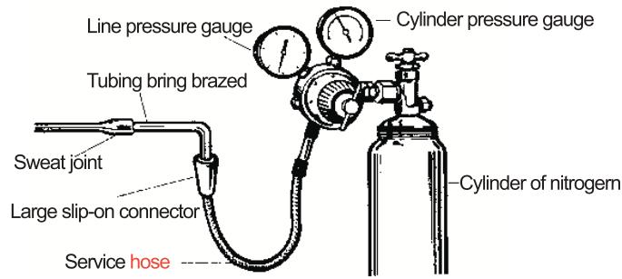
- The air tightness test adopts nitrogen tank to give pressure according to the pipe connection mode as the following figure shown.
- The gas and liquid valve are all in close state. In order to prevent the nitrogen entering the circulation system of outdoor unit, tighten the valve rod before giving pressure (both gas and liquid valve rods).
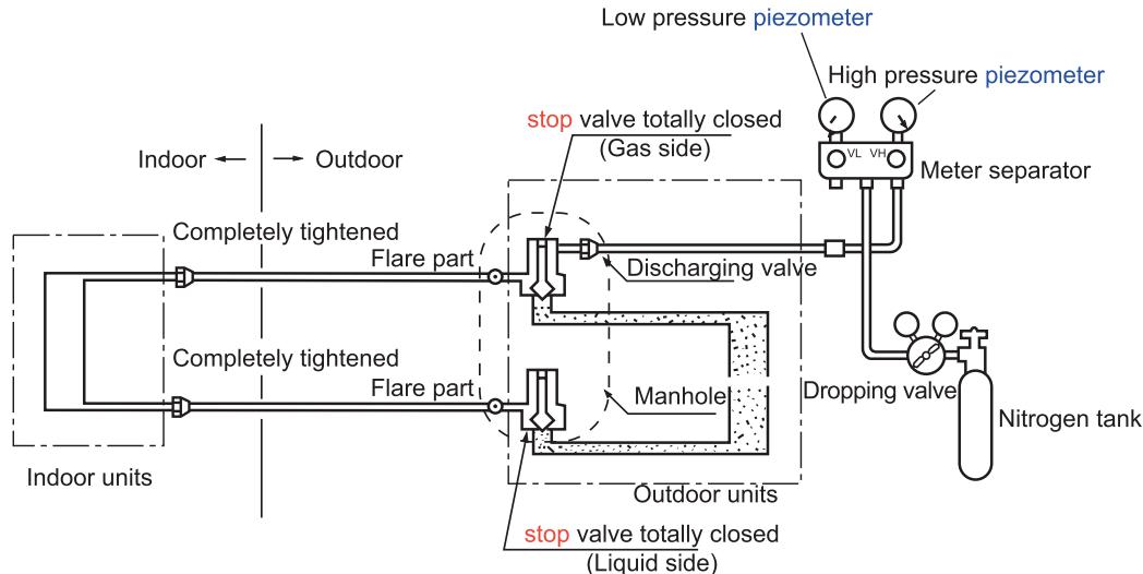
1) Pressurize for over 3 minutes at 0.3MPa (3.0kg / cm^2g)
2) Pressurize for over 3 minutes at 1.5 MPa ( 15 ~kg / cm^2 ~g ). A large leakage will be found.
3) Pressurize for about 24 hours at 3.0MPa ( 30kg/cm^2g ). A small leakage will be found.
- Check if the pressure drops
If the pressure does not drop, then pass.
If the pressure drops, then please check the leaking point.
When pressurizing for 24 hours, a variation of 1^ in the ambient temperature will cause a variation of 0.01MPa(0.1kg/cm^2g) in pressure. It shall be corrected during test.
- Checking the leaking point
In 1) to 3) steps, if the pressure drops, check the leakage in each joint by listening, touching and using soap water etc. to identify the leaking point. After confirming the leaking point, welding it again or tighten the nut tightly again.
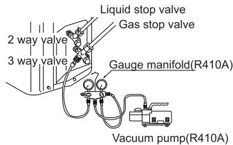
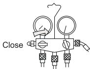
Piping vacuum method: to use vacuum pump (e.g.1U18FS1ERA)
- Detach the service port's cap of 3-way valve, the valve rod's cap for 2-way valve and 3-way valves, and connect the service port into the projection of charge hose (low) for gaugemanifold. Then connect the projection of charge hose (center) for gaugemanifold into vacuum pump.
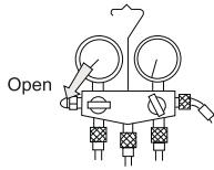
- Open the handle at low in gaugemanifold, and operate vacuum pump. If the scale-moves of gauge (low) reach vacuum condition in a moment, check the step 1 again.
- Vacuumize for over 15min. And check the level gauge which should read - 0.1MPa (-76 cm Hg) at low pressure side. After the completion of vacuumizing, close the handle 'Lo' in the vacuum pump. Check the condition of the scale and hold it for 1-2min. If the scale-moves back in spite of tightening, make flaring work again, then return to the beginning of the step 3.
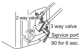
- Open the valve rod for the 2-way valve to an angle of anticlockwise 90 degree. After 6 seconds, close the 2-way valve and make the inspection of gas leakage.
2 way valve

3 way valve

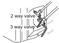
- No gas leakage? In case of gas leakage, tighten parts of pipe connection. If leakage stops, then proceed the step 6. If it does not stop gas leakage, discharge whole refrigerants from the service port. After flaring work again and vacuumize, fill up prescribed refrigerant from the gas cylinder.
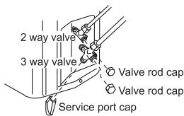
- Detach the charge hose from the service port, open 2-way valve and 3-way. Turn the valve rod anticlockwise until hitting lightly.
- To prevent the gas leakage, turn the service ports cap, the valve rodis cap for 2-way valve and 3-way's a little more than the point where the torque increases suddenly.
CAUTION:
If the refrigerant of the air conditioner leaks, it is necessary to make all the refrigerant out. Vacuumize first, then charge the liquid refrigerant into air conditioner according to the amount marked on the nameplate.
| WARNING! |
| DANGER OF BODILY INJURY OR DEATH |
| • TURN OFF ELECTRIC POWER AT CIRCUIT BREAKER OR POWER SOURCE BEFORE MAKING ANY ELECTRIC CONNECTIONS. |
| • GROUND CONNECTIONS MUST BE COMPLETED BEFORE MAKING LINE VOLTAGE CONNECTIONS. |
Precautions for Electrical wiring
- Electrical wiring work should be conducted only by authorized personnel.
- Do not connect more than three wires to the terminal block. Always use round type crimped terminal lugs with insulated grip on the ends of the wires.
- Use copper conductor only.
Selection of size of power supply and interconnecting wires
Select wire sizes and circuit protection from table below. (This table shows 20 m length wires with less than 2% voltage drop.)
| Item
Model | Phase | Circuit breaker | Power source wire size (minimum) (mm²) | Earth leakage breaker |
| Switch breaker (A) | Overcurrent protector rated capacity (A) | Switch breaker(A) | Leak current(mA) |
| 1U07BS1ERA | 1 | 40 | 26 | 2.5 | 40 | 30 |
| 1U09BS1ERA |
| 1U12BS1ERA |
| 1U18FS1ERA |
| 1U24GS1ERA | 1 | 40 | 26 | 4.0 | 40 | 30 |
- If the supply cord is damaged, it must be replaced by the manufacturer or its service agent or a similar qualified person.
- If the fuse of control box is broken, please change it with the type of T 25A/250V.
- The wiring method should be in line with the local wiring standard.
- The power cable and connecting cable should be self-provided.
- All the cables shall have got the European authentication certificate. During installation, when the connecting cables break off, it must be assured that the grounding wire is the last one to be broken off.
- The breaker of the air conditioner should be all-pole switch; and the distance between its two contacts should not be no less than 3mm . Such means for disconnection must be incorporation in the fixed wiring.
- The distance between its two terminal blocks of indoor unit and outdoor unit should not be over 5m . If exceeded, the diameter of the wire should be enlarged according to the local wiring standard.
- A leakage breaker must be installed.
Wiring procedure
1) Remove set screws on the side before taking off the front panel toward the direction.
2) Connect wires to the terminal block correctly and fix the wires with a wire clamp equipped nearby the terminal block.
3) Route the wires in a proper way and penetrate the wires through the opening for electrical wiring on the side panel.
WARNING:
INTERCONNECTING WIRES MUST BE WIRED ACCORDING TO FIGURE BELOW. INCORRECT WIRING MAY CAUSE EQUIPMENT DAMAGE.
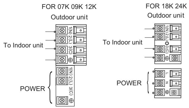
| Model | 1U07BS1ERA
1U09BS1ERA
1U12BS1ERA | 1U18FS1ERA | 1U24GS1ERA |
| Connecting wiring | ≥4G0.75mm² | ≥4G0.75mm² | ≥4G0.75mm² |
| Power cable | ≥3G1.5mm² | ≥3G2.5mm² | ≥3G4.0mm² |
CAUTION!
- THIS UNIT WILL BE STARTED INSTANTLY WITHOUT "ON" OPERATION WHEN ELECTRIC POWER IS SUPPLIED. BE SURE TO EXECUTE "OFF" OPERATION BEFORE ELECTRIC POWER IS DISCONNECTED FOR SERVICING.
- This unit has a function of automatic restart system after recovering power stoppage.
1. Before starting test run (for all Heat pump models)
Confirm whether the power source breaker (main switch) of the unit has been turned on for over 12 hrs to energize the crankcase heater in advance of operation.
2.Test run
Run the unit continuously for about 30 minutes, and check the following.
- Suction pressure at check joint of service valve for gas pipe.
- Discharge pressure at check joint on the compressor discharge pipe.
- Temperature difference between return air and supply air for indoor unit.
| Flash times of LED on mainboard | Trouble description | Analyze and diagnose |
| 1 | Eeprom failure | Outdoor main board eeprom fail |
| 2 | IPM failure | IPM failure |
| 4 | Communication error between main board and spdu module SPDU Communication error | Communication fail over 4min |
| 5 | High pressure protection | System high pressure over 4.15 Mpa |
| 6 | Module over-voltage protection (only for Spdu) Module lack-voltage protection (only for Spdu) | Send from Spdu module |
| 8 | Compressor discharging temperature protection | Compressor discharging temperature over 110 centigrade |
| 9 | Abnormal of DC moter | Jam of DC motor or motor failure |
| 10 | Abnormal of piping sensor | Piping sensor short-circuit or open-circuit |
| 11 | Suction temperature sensor failure | When the The wiring of compressor is wrong or the connection is poor |
| 12 | Abnormal of outdoor ambient sensor | Outdoor ambient sensor short-circuit or open-circuit |
| 13 | Abnormal of compressor discharge sensor | Compressor discharge sensor short-circuit or open-circuit |
| 15 | Communication error between indoor and outdoor unit | Communication fail over 4min |
| 16 | Lack of refrigerant | Check if there is leakage in the unit. |
| 17 | 4-way valve reverse failure | Alarm and stop if detect Tm<=15 last for 1min after compressor has started for 10min in heating mode, confirm the failure if it appears 3 times in one hour. |
| 18 | Compressor jam(only for spdu) | Inner compressor is abnormal jamed |
| 19 | Module PWM select circuit error | Module PWM select wrong circuit |
| 25 | Compressor U-phase over-current | The current of compressor U-phase is too high |
| 25 | Compressor V-phase over-current | The current of compressor V-phase is too high |
| 25 | Compressor W-phase over-current | The current of compressor W-phase is too high |
Haier Group
Address:No.1 Haier Road,Hi-tech Zone,Qingdao 266101 P.R.China
Contacts: TEL +86-532-8893-6943; FAX +86-532-8893-1010
Website: www.haier.com
CE
GWP=global warming potential
CONDITIONS D'ELIMINATION