
PAC BYAQX - Swimming Pool Edenea - Free user manual and instructions
Find the device manual for free PAC BYAQX Edenea in PDF.


| Product type | Pool heat pump |
| Brand | Edenea |
| Models | PAC BYAQX 107248, 107249, 107250, 107844 |
| Heat output | 8 to 16 kW depending on model |
| Power supply | 230 V single-phase or 400 V three-phase depending on model |
| Dimensions (L x W x H) | Approximately 1000 x 400 x 700 mm |
| Weight | Approximately 50 to 80 kg depending on model |
| Refrigerant | R32 or R410A |
| Operating range | Outside air temperature: -5°C to 43°C |
| Water temperature | Up to 40°C |
| Main functions | Water heating, integrated filtration, timer programming |
| Maintenance | Regular filter cleaning, refrigerant circuit check |
| Cleaning | Use a soft cloth and soapy water for the housing |
| Safety | Anti-freeze protection, overheat protection, automatic shutdown in case of fault |
| Spare parts | Available from the manufacturer or authorized dealer |
| Repairability | Repairability index: 8/10 (estimate) |
| Installation | Must be carried out by a qualified professional |
| Warranty | 2 years parts and labor |
Frequently Asked Questions - PAC BYAQX Edenea
User questions about PAC BYAQX Edenea
0 question about this device. Answer the ones you know or ask your own.
Ask a new question about this device
Download the instructions for your Swimming Pool in PDF format for free! Find your manual PAC BYAQX - Edenea and take your electronic device back in hand. On this page are published all the documents necessary for the use of your device. PAC BYAQX by Edenea.
USER MANUAL PAC BYAQX Edenea
MANUEL D'UTILISATION ET D'INSTALLATION
FR / EN / DE / NL / ESP

Résumé
3. Transport&stockage


Remarque :
2. Connecting your power wire
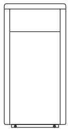
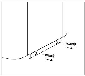


1 | 2


Important ! :
INSTALLATION AND USER MANUAL
FR / EN / DE / NL / ESP

Content
I. Application....4
II. Features....4
III. General information....5
IV. Technical Parameter....7
V. Dimension......8
VI. Installation instruction....9
VII. Operation instruction.... 13
VIII. Testing....15
IX. Precautions....16
X. Maintenance....17
XI. Trouble shooting for common faults.... 18
XII. Appendix 1: Heating priority (Optional)....20
XIII. Appendix 2: Heating priority (Optional)....21

Warning:
a. Please read the following tips before installation, use and maintenance.
b. Installation, removal and maintenance must be carried out by professional in accordance with the instructions.
c. Gas leakage test must be done before and after installation.
- Use
a. It must be installed or removed by professionals, and it is forbidden to dismantle and refit without permission.
b. Don't put obstacles before the air inlet and outlet of the heat pump.
- Installation
a. This product must be kept away from any source of fire.

b. The installation can't be in a closed environment or indoors, and must be kept well ventilated.

c. Vacuum completely before welding, field welding is not allowed, welding can only be performed by professional personnel in professional maintenance center.

d. Installation must be stopped if any gas leakage, and the unit must be returned to professional maintenance center.

3. Transportation & Storage
a. Sealing is not allowed during transportation
b. Transporting goods at a constant speed is needed to avoid sudden acceleration or sudden braking, so as to reduce the collision of goods.
c. The unit must be far away from any source of fire.
d. Storage place must be bright, wide, open and good ventilation, ventilation equipment is required.
4. Maintenance Notice
a. If maintenance or scrap is required, contact an authorized service center nearby
b. Qualification requirement
All operators who dispose gas must be qualified by valid certification which issued by professional agency.
c. Please strictly comply with the requirement from manufacturer when maintenance or filling gas. Please refer to the technical service manual.
Thank your choosing our product and your trust in our company. To help you get maximum pleasure from using this product, please read this instruction manual carefully and operate strictly according to the user manual before starting the machine, otherwise the machine may be damaged or cause you unnecessary harm.
I. Application
1- Set swimming pool water temp efficiently and economically to provide you comfort and pleasure.
2- User may choose the model technical parameter according to professional guide, this series of swimming pool heater has been optimized in factory (refer to technical parameter table).
II. Features
1- High efficient titanium heat exchanger.
2- Sensitive and accurate temp control and water temp display.
3- High pressure and low pressure protection.
4- Exceeding low temp auto stop protection.
5- Temp control compulsory defrosting.
6- International brand compressor.
7- Easy installation and operation.
III. General information
1. Contents:
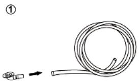
After unpacking, please check if you have all the following components.
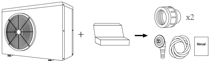

NOTICE:
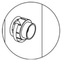
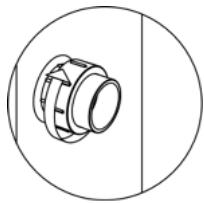
Please do not install wrong direction of the water union.
STEP 1

STEP 2

STEP 3

2. Operating conditions and range:
| Items | Range | |
| Operating range | Air temp | 0°C~43°C |
| Temp. setting | heating | 18°C~40°C |
| cooling | 12°C~30°C | |
The heat pump will have ideal performance in the operation range Air 15°C 25°C .
3. Advantages of different modes:
The heat pump has two modes: Smart and Silence. They have different advantages under different conditions.
| MODE | RECOMMENDATION | ADVANTAGES |
 | Smart modeAs standard | Heating capacity: 20% to 100% capacityIntelligent optimizationFast heating |
 | Silence modeUse at night | Heating capacity: 20% to 80% capacitySound level: 3dB (A) lower than Smart mode. |
IV. Technical Parameter
| Model | 107248 | 107249 | 107250 | 107844 |
| Advised pool volume (m3) | 14~28 | 20~35 | 20~40 | 30~55 |
| Operating air temperature (°C) | 0~43 | |||
| Performance Condition: Air 26°C, Water 26°C, Humidity 80% | ||||
| Heating capacity (kW) | 6.0 | 8.0 | 9.5 | 12.5 |
| C.O.P | 9.5~5.9 | 9.1~5.6 | 9.5~5.7 | 10.5~5.9 |
| C.O.P at 50% capacity | 8.5 | 8.0 | 8.3 | 9.2 |
| Performance Condition: Air 15°C, Water 26°C, Humidity 70% | ||||
| Heating capacity (kW) | 4.3 | 6.0 | 7.0 | 9.0 |
| C.O.P | 5.9~4.4 | 5.9~4.1 | 6.0~4.3 | 5.9~4.2 |
| C.O.P at 50% capacity | 5.8 | 5.9 | 5.6 | 5.8 |
| Performance Condition: Air 35°C, Water 28°C, Humidity 80% | ||||
| Cooling capacity (kW) | 2.2 | 3.3 | 3.8 | 4.9 |
| Rated input powerat air 15°C (kW) | 0.29~1.0 | 0.34~1.4 | 0.35~1.6 | 0.36~2.1 |
| Rated input currentat air 15°C (A) | 1.26~4.2 | 1.48~6.0 | 1.52~7.0 | 1.57~8.7 |
| Power supply | 230V/1 Ph/50Hz | |||
| Advised water flux (m3/h) | 2~4 | 2~4 | 3~4 | 4~6 |
| Water pipe in-out Spec (mm) | 50 | |||
| Net Dimension LxWxH (mm) | 744×359×648 | 864×359×648 | 864×359×648 | 864×359×648 |
| Net Weight (kg) | 42 | 46 | 47 | 49 |
Notice:
- This product can work well under air temp 0°C +43°C , efficiency will not be guaranteed out of this range. Please take into consideration that the pool heater performance and parameters are different under various conditions.
- Related parameters are subject to adjustment periodically for technical improvement without further notice. For details please refer to nameplate.
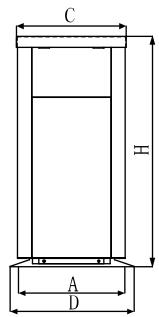
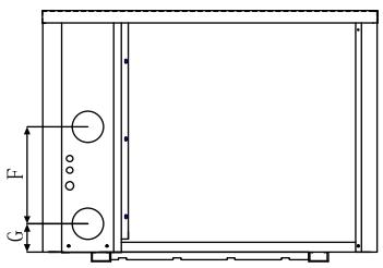
V. Dimension


| Size =MM | A | B | C | D | E | F | G | H | |
| MODEL | 107248 | 334 | 490 | 318 | 359 | 744 | 310 | 74 | 648 |
| 107249 | 334 | 560 | 318 | 359 | 864 | 250 | 74 | 648 | |
| 107250 | 334 | 560 | 318 | 359 | 864 | 250 | 74 | 648 | |
| 107844 | 334 | 560 | 318 | 359 | 864 | 320 | 74 | 648 |
※ Above data is subject to modification without notice.
Note:
The picture above is the specification diagram of the pool heater, for technician's installation and layout reference only. The product is subject to adjustment periodically for improvement without further notice.
VI. Installation instruction
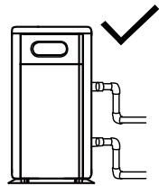
1. Drawing for water pipes connection
![graph LR A["Signal Cable"] --> B["Power cord"] B --> C["Inlet"] C --> D["Outlet"] D --> E["Water to swimming pool"] E --> F["Water Processor"] F --> G["water switch"] G --> H["Pump"] H --> I["Pool water in"] I --> J["Filter"] J --> K["Drainage"]](/content/2026/07/1489010/images/640caec0c52fe6b55f18feb0d312b1d0d83881049dac2272da1cfd8abdf19889.jpg)
(Notice: The drawing is just for demonstration, and layout of the pipes is only for reference.)
2. Connecting your power wire

(Note: please open the back panel for power connection. The operation is the same as above.)
For power supply: 230V 50Hz
![graph LR A["Distribution Box (Customer prepare)"] --> B["Breaker"] B --> C["Power Cord"] C --> D["Swimming Pool Heat Pump Wiring Board"] E["Power Supply 230V 50Hz"] --> F["L N"] F --> G["⊕"] G --> H["Fuse"] H --> I["Switch"] I --> J["Power Cord"] J --> K["Switch"] K --> L["Power Cord"] L --> M["Swit…](/content/2026/07/1489010/images/7110b8c5011fcc7026c074ca387111d18bbff06063ff0c2929b206244d8aaf65.jpg)
Note:
⚠️ Must be hard wired, no plug allowed.
⚠️ The swimming pool heater must be earthed well.
3. Electric Wiring Diagram
Options for protecting devices and cable specification
| MODEL | 107248 | 107249 | 107250 | 107844 | |
| Breaker | Rated Current (A) | 8.0 | 9.5 | 11.5 | 15.0 |
| Rated Residual Action Current (mA) | 30 | 30 | 30 | 30 | |
| Fuse (A) | 8.0 | 9.5 | 11.5 | 15.0 | |
| Power Cord (mm 2 ) | 3×1.5 | 3×1.5 | 3×2.5 | 3×2.5 | |
| Signal cable (mm 2 ) | 3×0.5 | 3×0.5 | 3×0.5 | 3×0.5 | |
※ Above data is subject to modification without notice.
Note: The above data is adapted to power cord ≤ 10m. If power cord is >10m, wire diameter must be increased. The signal cable can be extended to 50m at most.
4. Installation instruction and requirement
The heat pump must be installed by a professional team. The users are not qualified to install by themselves, otherwise the heat pump might be damaged and risky for users' safety.
A. Installation
1) The inlet and outlet water unions can't bear the weight of soft pipes. The heat pump must be connected with hard pipes!


2) In order to guarantee the heating efficiency, the water pipe length should be ≤10m between the pool and the heat pump.
B. Installation instruction
1) Location and size
The heat pump should be installed in a place with good ventilation

2) The frame must be fixed by bolts (M10) to concrete foundation or brackets. The concrete foundation must be solid and fastened; the bracket must be strong enough antirust treated;
3) Please don't stack substances that will block air flow near inlet or outlet area, and there is no barrier within 50cm behind the main machine, or the efficiency of the heater will be reduced or even stopped;
4) The machine needs an appended pump (Supplied by the user). The recommended pump specification-flux: refer to Technical Parameter, Max. Lift ≥ 10m;
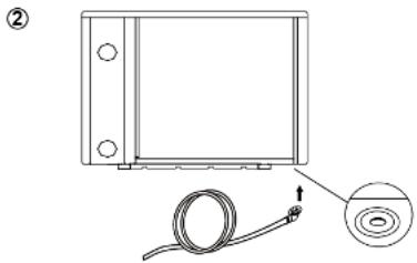
5) When the machine is running, there will be condensation water discharged from the bottom, please pay attention to it. Please hold the drainage nozzle (accessory) into the hole and clip it well, and then connect a pipe to drain the condensation water out.
C. Wiring
1) Connect to appropriate power supply, the voltage should comply with the rated voltage of the products.
2) Earth the machine well.
3) Wiring must be handled by a professional technician according to the circuit diagram.
4) Set leakage protector according to the local code for wiring (leakage operating current ≤ 30mA).
5) The layout of power cable and signal cable should be orderly and not affecting each other.
D. Switch on after finishing all wiring construction and re-checking.
VII. Operation instruction
Picture for keys

| SYMBOL | DESIGNATION | OPERATION |
| Power ON/OFF | Press to power on or off the heat pump | |
| Mode | Press to select Smart/Silence modeSmart mode:100%-20% capacitySilence mode:80%-20% capacity | |
| Heat/Cool/Auto | Press to shift among Auto (12~40°C)Heating (18~40°C) Cooling (12~30°C) | |
| Up/ Down | Press to set desired water temperature |
Note:
- Switch on/off: In the power on state, press ⏻ to turn on the power. When the power is on, press ⏻ to turn it off.
- You may set the desired water temperature from 12 to 40°C.
- The center of the screen shows the inlet pool temperature, when the up and down keys are pressed, the digital flashing displays the set temperature.
- After you turn on the heat pump, the fan will start to run in 3 minutes. In another 30 seconds, the compressor will start to run.
-
During heating, the ⚙□ will be light. During cooling, ⚙□ will be light. During auto heating cooling, ⚙□ and ⚙□ will be both light.
-
Mode selections
1) Smart ■ will be light as standard when you turn on the heat pump.
2) Press the Mode button to enter the Silence mode, the Silence ■ will be light.
3) Press the Mode button again to exit and enter the SMART mode.
- Defrosting
1) Automatic defrost:
When the machine is automatically defrosted, the ⚙️ will flashes, and after the defrost is completed, it automatically jumps to the operation mode before defrosting.
2) Compulsory defrosting
When the heat pump is heating and the compressor is working continuously for 10 minutes, press both “Mode” and “▼” buttons for 5 seconds to start compulsory defrosting. (Note: the interval between compulsory defrosting should be more than 30 minutes.)
The heating light will be twinkling when heat pump is in compulsory or auto defrosting.
The running process and ending of compulsory defrosting are the same as auto-defrosting.
- Temperature display conversion between ° C and ° F:
Press " ▲" and " ▼" together for 5 seconds to switch between °C and °F.
VIII. Testing
1. Inspection before use
A. Check installation of the whole machine and the pipe connections according to the pipe connecting drawing;
B. Check the electric wiring according to the electric wiring diagram and earthing connection;
C. Make sure that the main machine power switch is off;
D. Check the temperature setting;
E. Check the air inlet and outlet.
2. Trial
A. The user must “Start the Pump before the Machine, and Turn off the Machine before the Pump”, or the machine will be damaged;
B. The user should start the pump, check for any leakage of water; and then set suitable temperature in the thermostat, and then switch on power supply;
C. In order to protect the swimming pool heater, the machine is equipped with a time lag starting function, when starting the machine, the blower will run 1 minute earlier than the compressor;
D. After the swimming pool heater starts up, check for any abnormal noise from the machine.
IX. Precautions
1. Attention
A. Set proper temperature in order to get comfortable water temperature to avoid overheating or overcooling;
B. Please don't stack substances that can block air flow near inlet or outlet area, or the efficiency of the heater will be reduced or even stopped;
C. Please don't put hands into outlet of the swimming pool heater, and don't remove the screen of the fan at any time;
D. If there are abnormal conditions such as noise, smell, smoke and electrical leakage, please switch off the machine immediately and contact the local dealer. Don't try to repair it yourself;
E. Don't use or stock combustible gas or liquid such as thinners, paint and fuel to avoid fire;
F. In order to optimize the heating effect, please install heat preservation insulation on pipes between swimming pool and the heater. During running period of the swimming pool heater, please use a recommended cover on the swimming pool;
G. Connecting pipes of the swimming pool and the heater should be ≤ 10m, or the heating effect of the heater cannot be ensured;
H. This series of machines can achieve high efficiency under air temperature of +15°C +25°C .
2. Safety
A. Please keep the main power supply switch far away from the children;
B. When a power cut happens during running, and later the power is restored, the heater will start up automatically. So please switch off the power supply when there is a power cut, and reset temp when power is restored;
C. Please switch off the main power supply in lightning and storm weather to prevent from machine damage that caused by lightning;
D. If the machine is stopped for a long time, please cut off the power supply and drain water clear of the machine by opening the tap of inlet pipe.
X. Maintenance
Caution: Danger of electric shock
“Cut off” power supply of the heater before cleaning, examination and repairing
A. In winter season when you don't swim:
- Cut off power supply to prevent any machine damage
- Drain water clear of the machine.

!!Important:
Unscrew the water nozzle of inlet pipe to let the water flow out.
When the water in machine freezes in winter season, the titanium heat exchanger may be damaged.
- Cover the machine body when not in use.
B. Please clean this machine with household detergents or clean water, NEVER use gasoline, thinners or any similar fuel.
C. Check bolts, cables and connections regularly.
XI. Trouble shooting for common faults
| Failure | Reason | Solution |
| Heat pump doesn’t run | No power | Wait until the power recovers |
| Power switch is off | Switch on the power | |
| Fuse burned | Check and change the fuse | |
| The breaker is off | Check and turn on the breaker | |
| Fan running but with insufficient heating | evaporator blocked | Remove the obstacles |
| Air outlet blocked | Remove the obstacles | |
| 3 minutes start delay | Wait patiently | |
| Display normal, but no heating | Set temp. too low | Set proper heating temp. |
| 3 minutes start delay | Wait patiently | |
| If above solutions don’t work, please contact your installer with detailed information and your model number. Don’t try to repair it yourself. | ||
Note: If the following conditions happen, please stop the machine immediately, and cut off the power supply immediately, then contact your dealer:
a) Inaccurate switch action;
b) The fuse is frequently broken or leakage circuit breaker jumped.
Failure code
| NO. | DISPLAY | NOT FAILURE DESCRIPTION |
| 1 | E3 | No water protection |
| 2 | E5 | Power supply excesses operation range |
| 3 | E6 | Excessive temp difference between inlet and outlet water(Insufficient water flow protection) |
| 4 | Eb | Ambient temperature too high or too low protection |
| 5 | Ed | Anti-freezing reminder |
| NO. | DISPLAY | FAILURE DESCRIPTION |
| 1 | E1 | High pressure protection |
| 2 | E2 | Low pressure protection |
| 3 | E4 | Phases lack protection (three phase model only) |
| 4 | E7 | Water outlet temp too high or too low protection |
| 5 | E8 | High exhaust temp protection |
| 6 | EA | Evaporator overheat protection (only at cooling mode) |
| 7 | P0 | Controller communication failure |
| 8 | P1 | Water inlet temp sensor failure |
| 9 | P2 | Water outlet temp sensor failure |
| 10 | P3 | Gas exhaust temp sensor failure |
| 11 | P4 | Evaporator coil pipe temp sensor failure |
| 12 | P5 | Gas return temp sensor failure |
| 13 | P6 | Cooling coil pipe temp sensor failure |
| 14 | P7 | Ambient temp sensor failure |
| 15 | P8 | Cooling plate sensor failure |
| 16 | P9 | Current sensor failure |
| 17 | PA | Restart memory failure |
| 18 | F1 | Compressor drive module failure |
| 19 | F2 | PFC module failure |
| 20 | F3 | Compressor start failure |
| 21 | F4 | Compressor running failure |
| 22 | F5 | Inverter board over current protection |
| 23 | F6 | Inverter board overheat protection |
| 24 | F7 | Current protection |
| 25 | F8 | Cooling plate overheat protection |
| 26 | F9 | Fan motor failure |
| 27 | Fb | Capacitor no charging protection |
| 28 | FA | PFC module over current protection |
XII. Appendix 1: Heating priority (Optional)
![graph TD A["For water pump: Voltage 230V, Capacity ≤500W"] --> B["Breaker/fuse (Customer prepare)"] B --> C["Power Supply 230V~50Hz"] C --> D["Earthing"] D --> E["Power Supply"] E --> F["Water Pump"] F --> G["Breaker/fuse (Customer prepare)"] G --> H["Power Supply 230V~50Hz"] H --> I["Earthing"] I -…](/content/2026/07/1489010/images/ff42cc1fb5facf96ef60132e75194bd74836818860bfb498905a5757c1d58a30.jpg)
XIII. Appendix 2: Heating priority (Optional)
For water pump: Voltage 230V, Capacity >500W
![graph TD A["Power Supply 230V~50Hz"] --> B["Breaker/fuse (Customer prepare)"] B --> C["Power Cord"] D["L N"] --> E["P1 P2"] E --> F["Water Pump"] G["Power Supply 230V~50Hz"] --> H["Breaker/fuse (Customer prepare)"] H --> I["contactor"] I --> J["Water Pump"] K["Earthing"] --> L["Earthing"] M["Power S…](/content/2026/07/1489010/images/2cf71adff420ff8c6d00cf29fff3a3fec3b72d4051f522169e2c210ab251dde6.jpg)
Parallel connection with filtration clock
A: Water pump timer

B: Water pump wiring of Heat Pump
Note: The installer should connect A parallel with B (as above picture). To start the water pump, condition A or B is connected. To stop the water pump, both A and B should be disconnected.
The factory reserves the final interpretation right.
And keep the right to stop or change product specification and design without prior notice at any time, no need to bear the resulting obligations.
Guarantee
The AQUALUX INVERTER heat pump is guaranteed against all material and/or manufacturing defects for 3 years as from the date of delivery.
The titanium exchanger is guaranteed against rust for 3 years as from the date of delivery.
The couplings exchanger are not covered by the warranty in case of impact or not properly handling (do not lift heat pumps with the couplings).
The exchanger is not covered under warranty in case of non-observance of wintering
procedure (ex burst by frost).
These guarantees are granted subject to strict compliance with the assembly and maintenance instructions. The guarantee will not apply in the event of non-compliance with these conditions.
No guarantee can be granted if the goods have not been paid for in full.
No repairs or replacements carried out under guarantee can result in any prolongation of the said period of guarantee.
The purchase invoice must be forwarded with any claims under guarantee.
Under the terms of this guarantee, the sole obligation placed on AQUALUX is replacement or repair free of charge, as AQUALUX sees fit, of the product or element found to be defective by the competent AQUALUX department. All other costs must be met by the purchaser.
To benefit from this guarantee, all the products concerned must be forwarded beforehand to the AQUALUX after-sales department, whose approval is essential for all replacements or repairs in workshop.
The guarantee does not cover visible defects. Does not cover defects or damage caused by normal wear and tear, defects resulting from faulty assembly and/or misuse, or any modifications made to the product without the prior written approval of AQUALUX.
Legal guarantee: provided that the purchaser is able to provide proof of a hidden defect, the seller is required by law to make good all the consequences thereof (article 1641 and seq. of the French civil code).
If the purchaser brings a claim before the courts, he must do so in a short time from the date at which the defect is detected (article 1648 of the French civil code).
ECO PARTICIPATION (DEEE directive)
In accordance with the European Directive 2002/96/EC, and in order to reach a number of environmental protection objectives, the following rules must be obeyed.

These objectives apply to waste from electrical and electronic equipment (DEEE).
The pictogram attached to the product, the user manual and the packaging indicates that the product is subject to this regulation.
Consumers must return the used products to the collection points provided.
By enabling the products to be recycled, consumers contribute to the protection of our environment. This is an ecological gesture.
287 Ave de la Massane - 13210 SAINT REMY DE PROVENCE - France
commerce@aqualux.com / www.aqualux.com
INSTALLATIONS
UND
BENUTZERHANDBUCH
FR / EN / DE / NL / ESP

Inhaltsverzeichnis

NOTIZ:

| GRÖßE =MM | A | B | C | D | E | F | G | H | |
| MODELL | 107248 | 334 | 490 | 318 | 359 | 744 | 310 | 74 | 648 |
| 107249 | 334 | 560 | 318 | 359 | 864 | 250 | 74 | 648 | |
| 107250 | 334 | 560 | 318 | 359 | 864 | 250 | 74 | 648 | |
| 107844 | 334 | 560 | 318 | 359 | 864 | 320 | 74 | 648 |

Content
3. Transport & Opslag


OPMERKING:
STEP 2

STEP 3
2. Operating conditions and range:


| SIZE =MM | A | B | C | D | E | F | G | H | |
| MODEL | 107248 | 334 | 490 | 318 | 359 | 744 | 310 | 74 | 648 |
| 107249 | 334 | 560 | 318 | 359 | 864 | 250 | 74 | 648 | |
| 107250 | 334 | 560 | 318 | 359 | 864 | 250 | 74 | 648 | |
| 107844 | 334 | 560 | 318 | 359 | 864 | 320 | 74 | 648 |

Belangrijk!
Contenido
I. Uso....4


NOTA:
STEP 2

STEP 3

| TAMAÑO=MM | A | B | C | D | E | F | G | H | |
| MODELO | 107248 | 334 | 490 | 318 | 359 | 744 | 310 | 74 | 648 |
| 107249 | 334 | 560 | 318 | 359 | 864 | 250 | 74 | 648 | |
| 107250 | 334 | 560 | 318 | 359 | 864 | 250 | 74 | 648 | |
| 107844 | 334 | 560 | 318 | 359 | 864 | 320 | 74 | 648 |


1/3


!!Importante:
- MANUEL D'UTILISATION ET D'INSTALLATION
- RÉSUMÉ
- TRANSPORT&STOCKAGE
- REMARQUE
- CONNECTING YOUR POWER WIRE
- IMPORTANT
- INSTALLATION AND USER MANUAL
- CONTENT
- WARNING
- TRANSPORTATION & STORAGE
- MAINTENANCE NOTICE
- APPLICATION
- FEATURES
- GENERAL INFORMATION
- CONTENTS
- NOTICE
- OPERATING CONDITIONS AND RANGE
- ADVANTAGES OF DIFFERENT MODES
- TECHNICAL PARAMETER
- DIMENSION
- NOTE
- INSTALLATION INSTRUCTION
- DRAWING FOR WATER PIPES CONNECTION
- ELECTRIC WIRING DIAGRAM
- INSTALLATION INSTRUCTION AND REQUIREMENT
- INSTALLATION
- WIRING
- OPERATION INSTRUCTION
- TESTING
- INSPECTION BEFORE USE
- TRIAL
- PRECAUTIONS
- ATTENTION
- SAFETY
- MAINTENANCE
- CAUTION: DANGER OF ELECTRIC SHOCK
- TROUBLE SHOOTING FOR COMMON FAULTS
- APPENDIX 2: HEATING PRIORITY (OPTIONAL)
- PARALLEL CONNECTION WITH FILTRATION CLOCK
- GUARANTEE
- ECO PARTICIPATION (DEEE DIRECTIVE)
- INSTALLATIONS
- UND
- BENUTZERHANDBUCH
- INHALTSVERZEICHNIS
- NOTIZ
- TRANSPORT & OPSLAG
- OPMERKING
- BELANGRIJK
- CONTENIDO
- NOTA
- IMPORTANTE
Brand : Edenea
Model : PAC BYAQX
Category : Swimming Pool