
Fixation du Kit Turbine 1000 - Wood stove SUPRA - Free user manual and instructions
Find the device manual for free Fixation du Kit Turbine 1000 SUPRA in PDF.


| Product type | Wood stove with turbine kit |
| Brand | SUPRA |
| Model | Mounting of turbine kit 1000 on the fireplace |
| Dimensions (H x W x D) | 1000 x 600 x 600 mm |
| Weight | 150 kg |
| Material | Steel, cast iron, ceramic glass |
| Fuel | Wood logs (max 50 cm) |
| Nominal power | 10 kW |
| Energy efficiency | 80 % |
| Main functions | Heating, hot air diffusion via turbine |
| Maintenance and cleaning | Glass cleaning, ash pan emptying, annual chimney sweeping |
| Safety | Minimum distance to combustible materials: 1 m, tempered glass, cool handle |
| Spare parts and repairability | Turbine kit, seals, grate, ash pan available |
| General information | Compliant with European standards, Flamme Verte 7-star label |
Frequently Asked Questions - Fixation du Kit Turbine 1000 SUPRA
User questions about Fixation du Kit Turbine 1000 SUPRA
0 question about this device. Answer the ones you know or ask your own.
Ask a new question about this device
Download the instructions for your Wood stove in PDF format for free! Find your manual Fixation du Kit Turbine 1000 - SUPRA and take your electronic device back in hand. On this page are published all the documents necessary for the use of your device. Fixation du Kit Turbine 1000 by SUPRA.
USER MANUAL Fixation du Kit Turbine 1000 SUPRA
natural_image
Technical line drawing of a two-tiered industrial oven and support structure (no text or symbols)natural_image
Line drawing of a rectangular oven with four circular vented outlets and a side panel (no text or symbols)GB INSTRUCTIONS FOR INSTALLATION AND USE
ACCELERATEUR DE CONVECTION KTE152 ACCELERATORE DI CONVEZIONE KTE152 GEBLÄSE-SET KTE152
This appliance is in conformity with the requirements of the EEC directives of electromagnetic compatibility 89/336/EEC and the low voltage 73/23/EEC
FOCOLARI INTERESSATI
- Focolari classici -(148,150,152,158,160,162,168, ...-(B,C,D,VL,VLD)
- HF 120C / HF 121C / HF 131C
- Integrale 8
- Granito 22 / 24 / 26
FOCOLARI INTERESSATI
| 1602 | Cristal |
| 4900-4901-4902 | Diademe |
| 5100-5101-5102 | Elodie |
| 5600-5601-5602 | Empyrium |
| 5800-5801-5802 | Equation |
| Agathe | Flavie |
| Altima | FSU6 |
| Aravis | FSU9 |
| Carat | Granit 20 |
3
FOCOLARI INTERESSATI
A) Focolari con vetro prismatico o sagomato FV 40 Vertal
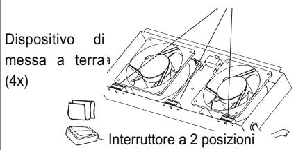
The convection accelerator is fitted with 2 axial flow fans. The 2-position switch enables the fans to be operated at 2 speeds.
| Kit flow rate at max speed | 240 m3/h |
| Input power | 15 W |
| Intensity | 120 mA |
| Voltage / Frequency | 230 V / 50 Hz |
| Noise | 33 dB |
2. ASSEMBLING THE KTE 152
2.1. Package inventory
- one convection accelerator unit
- one metal baffle + fastening screws (only to be used with traditional fireboxes).
- one switch package (see §4 "Electrical Connection")
2.2. Horizontal assembly WITH metal baffle
FIREBOXES CONCERNED
- Classics -(148,150,152,158,160,162,168, ...-(B,C,D,VL,VLD)
- HF 120C / HF 121C / HF 131C
- Integral 8
- Granit 22 / 24 / 26
The metal baffle must be used
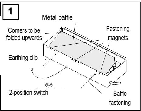
- Fit the metal baffle to the unit (fig. 1).
- Insert the unit from underneath the firebox already in place (fig.2).
- Push it firmly home and pivot it so that the magnets make correct contact with the bottom plate.
- Check that it is correctly positioned and fold back the safety lug.- Connect the earthing clip to the firebox through the lug opening.- Make the electrical connection.

2.3. Horizontal assembly WITHOUT metal baffle
Do not use the metal baffle!
- Insert the unit from underneath the firebox already in place
- Push it firmly home and pivot it so that the magnets make correct contact with the bottom plate.
- Check that it is correctly positioned and fold back the safety lug.
- Connect the earthing clip to the firebox through the lug opening.
- Make the electrical connection.
FIREBOXES CONCERNED
| 1602 | Cristal |
| 4900-4901-4902 | Diademe |
| 5100-5101-5102 | Elodie |
| 5600-5601-5602 | Empyrium |
| 5800-5801-5802 | Equation |
| Agathe | Flavie |
| Altima | FSU6 |
| Aravis | FSU9 |
| Carat | Granit 20 |

Result
Rubis
Taranis
Temporis
Univers
Vallauris
Valloire
Vanoise/ Vanoise R
2.4. Vertical assembly WITHOUT metal baffle
APPLIANCES CONCERNED
A) Fireboxes with prismatic or curved glass FV 40 Vertical Antibia
Do not use the metal baffle
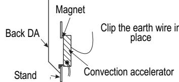
- Position the fan unit opposite the rectangular opening provided on the back of the stand (fig.5).
- Fasten it in place by resting the lower fastening lug on the lower edge of the rectangular opening in the stand. The magnets stick to the back of the stand (Fig. 5 and 6).
- Connect the earthing clip to the firebox through the lug opening.
- Make the electrical connection.
5
Rectangular opening

6
APPLIANCES CONCERNED
B) BEAUFORT wood-burning stove
Do not use the metal baffle!
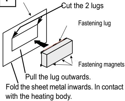
- Position the fan unit opposite the rectangular opening provided on the back of the stand (fig. 7).
- Fasten it in place by resting the upper fastening lug on the upper edge of the rectangular opening in the stand. The magnets stick to the back of the stand (Fig. 7 and 8).
- Connect the earthing clip to the firebox through the lug opening.
- Make the electrical connection.
7
Rectangular opening
8
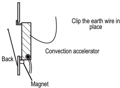
2.5. Assembly WITHOUT metal baffle
APPLIANCES CONCERNED
"Vanoise-Vanoise R
9



Before accessing connection parts, the power to all the supply circuits must be switched off.
4.1. Inventory
NB: this switch package is identical for both kits.
It comprises the following components:
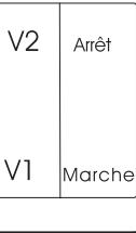
- one 2-position switch, not fitted.
- one 3 m 4-conductor electrical cable to connect the convection accelerator to the switch. This length allows sufficient freedom to place the 2-position switch in the optimum location.
Electrical wire 0.75 mm 2 ; 6 cm (bridging) - The current input (3 x 0.75 mm 4 ) (220 V / 50 Hz) to the switch is not provided.
- one split fitting, to be cut in two.
4.2. Electrical connection
- Locate the live terminal on the junction box outlet using a voltage testing screwdriver. The live conductor (L) will be connected to this terminal. It must be routed via an omnipolar safety device with a contact opening distance of at least 3 mm.
- Position the connection plate as shown with the letters LA (Live) ?turned to the bottom right.
- Prepare the electrical bridge, 0.75 mm2 , length 6 cm.
-
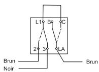
Strip the 3 conductors on the current supply and connect them as shown (fig. 12):
-
the live conductor (L) to terminal LA.
- the neutral conductor (N) to the 1/2 split fitting.
-
the earth conductor () to the other 1/2 split fitting.
-
Then bring together the 4 conductors on the cable supplied (shortened if necessary) and connect them, respecting the colour-coding (fig. 12).
• Fix the plate in the place provided. - Place the switch housing so that it contains all the wiring by placing the split fittings in the corners and clip it onto the plate.
- Fit the 2 covers as shown and clip them to the switches.
- Switch on the power and check that it works.
11

Electrical schematics
5. MAINTENANCE
After a certain period of use, dust may clog the protective grates. The appliance can be cleaned by pulling it downwards and to the front of the firebox (access under the coping stone).
Leave this access under the coping stone clear.
Electrical appliances must not be disposed of with household waste.
Please recycle them at the collection points provided for this purpose.
Contact your local authority or your dealer to obtain advice on recycling.


- FOCOLARI INTERESSATI
- ASSEMBLING THE KTE 152
- Package inventory
- Horizontal assembly WITH metal baffle
- FIREBOXES CONCERNED
- The metal baffle must be used
- Horizontal assembly WITHOUT metal baffle
- Do not use the metal baffle!
- Vertical assembly WITHOUT metal baffle
- APPLIANCES CONCERNED
- Do not use the metal baffle
- Assembly WITHOUT metal baffle
- Before accessing connection parts, the power to all the supply circuits must be switched off.
- Inventory
- Electrical connection
- MAINTENANCE
- Leave this access under the coping stone clear.
Brand : SUPRA
Model : Fixation du Kit Turbine 1000
Category : Wood stove