RA30 - Tubular motor CHAMBERLAIN - Free user manual and instructions
Find the device manual for free RA30 CHAMBERLAIN in PDF.

User questions about RA30 CHAMBERLAIN
0 question about this device. Answer the ones you know or ask your own.
Ask a new question about this device
Download the instructions for your Tubular motor in PDF format for free! Find your manual RA30 - CHAMBERLAIN and take your electronic device back in hand. On this page are published all the documents necessary for the use of your device. RA30 by CHAMBERLAIN.
USER MANUAL RA30 CHAMBERLAIN
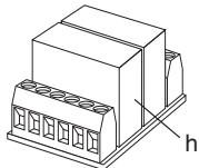
(h) WTMZ1
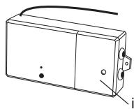
(i) TCRX3ED
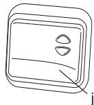
(j) TCTX2ED
TCRX2ED
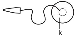
(k) WTMLS1
(I) TCL5E
(m) 703280
Description
Moteur 10Nm / 35mm
Moteur 14Nm / 45mm
Moteur 19Nm / 45mm
Moteur 36Nm / 45mm
Adaptateur rainure, 78mm
Adaptateur rainure, 85mm
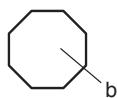
Axe octogonal 40mm - 2m (40mm)
Axe octogonal 60mm - 1m
Axe octogonal 60mm - 2m
Axe octogonal 60mm - 3m
Caution! Non-compliance can result in serious injury.

Any work on the electrical installation including servicing may only be performed by a qualified electrician.

Do not allow children to play with the controls.
Check shutter or sun-blind system regularly for signs of wear and damage. Damaged systems should not be used under any circumstances until such time as they have been repaired.

Observe shutter or sun-blind system carefully whilst in operation.

Switch off shutter or sun-blind system and disconnect from mains supply, if any servicing or cleaning has to be done either on the system itself or in its immediate vicinity.

Ensure that the motor is accessible after installation.

Ensure sufficient room (at least 40~cm ) is left between any moving parts and nearby objects.

Ensure system cannot trap or cut persons and secure relevant parts.
Correct use
Type RA10 - RA50 tubular drives are designed for the exclusive purpose of operating shutters and sun-blind systems.
In compliance with standard EN 60 335-2-97:2000, the cable connecting the RA10 drive to the mains cable must be laid internally.
EJOT Delta PT 40x12 WN 5454 Torx (9900 000 545 4) is the only type of screw that can be used to fasten the connecting parts to the RA10 motor.
Any other form of usage is deemed to be incorrect. Neither the manufacturer nor the supplier assumes any liability for personal injury, damage to property or consequential injury or damage occurring as a result of the use of the control units and / or drives for purposes other than those mentioned above or due to changes made to the equipment affecting the safety of the given system.
The details stipulated in the Operating Instructions in respect of the operation and repair of the system require strict observance. Neither the manufacturer nor the supplier assumes any liability for personal injury, damage to property or consequential injury or damage occurring as a result of non-compliant actions.
IMPORTANT SAFETY INSTRUCTIONS FOR THE FITTER

Caution! Non-compliance can result in serious injury. Observe EN 60 335-2-97:2000 Safety Instructions in full.
Any work on the electrical installation may only be performed by a qualified electrician.
When electrical or electronic systems and appliances are in operation, certain components are live, which can constitute a risk. Any touching of and work performed on the equipment by persons not qualified to do so or non-compliance with safety instructions can result in personal injury or damage to property.
All the standards and regulations applying to electrical installations must be observed.
Only those spare parts, tools and other equipment as have been approved by Chamberlain may be used.
Neither the manufacturer nor the supplier assumes any liability for personal injury, damage to property or consequential injury or damage occurring as a result of the use of non-approved third party products or changes made to any accessories.
Prior to performing installation work, de-activate all connections and control facilities that are not absolutely essential for operation of the given system.
Fit control facilities within sight of the product to be controlled at a height of at least 1.5m
Ensure sufficient room is left between any moving parts and nearby objects.
Torque rating and duty cycle must comply with the requirements of the product to be driven
Technical data - torque rating and duty cycle details can be found on the tubular drive's data plate.
Ensure system cannot trap or cut persons and secure relevant parts.
Observe safety margins as stipulated in DIN EN 294.
Please consult Chamberlain product information for further details.
Declaration of Conformity
Tubular Motor... RA10 -RA20 - RA30 - RA50 is in conformity to the applicable sections of Standards .EN55014, EN610003, ETS RES 0908, EN60555, & EN60335-1
per the provisions & all amendments of EU Directives. 73/23/EEC, 89/336EEC
Declaration of Incorporation
Tubular Motor Model RA10, RA20, RA30 and RA540, when installed and maintained according to all the Manufacturer's instructions in combination with a shutter which has also been installed and maintained according to all the Manufacturer's instructions, meets the provisions of EU Directive 89/392EEC and all amendments.
I, the undersigned, hereby declare that the equipment specified above and any accessory listed in the manual conforms to the above Directives and Standards.
Chamberlain GmbH
D-66793 Saarwellingen
March, 2002

Wu
Colin B. Willmott
Chief Engineer
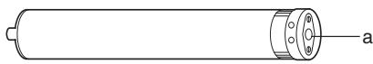
- Motor (1)
- Hardwarebag
- Adjuster pin (2)
- Drive adapter safety catch(RA10 - RA30) (3) (RA50) (4)
- Square pin (RA50) (5)
- Square pin 25mm (RA10 - RA30) (6)
(3) Manual
(4)Drive adapter (7)
(5)Mounting bracket (8)
Before You Begin:
- Carefully read all the information contained in this Owner's Manual before beginning installation procedures.
- Check the shutter to be sure it is not broken or damaged, and that it opens and closes smoothly.
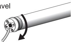
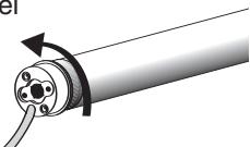
- Determine whether the motor needs to be installed on the left side (a) or the right side, (b) of the shutter - Figure . Install it on the side where the manual pull is located. Close the shutter.
- Ensure that the motor can be pushed in as far as the stop. The limit switch is controlled by the plastic ring which must be pushed fully on.
Tubular Motors with mechanical limit switches
| Model | Diameter | Torque | Speed | Operating Voltage | Frequency | Current input | Motor Rating | Operating time | Limit Switch Range |
| (mm) | (Nm) | (RPM) | (V) | (Hz) | (A) | (W) | (min) | (U) | |
| RA10 | 35 | 10 | 14 | 230 | 50 | 0.40 | 100 | 4 | 38 |
| RA20 | 45 | 14 | 15 | 230 | 50 | 0.67 | 155 | 4 | 38 |
| RA30 | 45 | 19 | 15 | 230 | 50 | 0.77 | 175 | 4 | 38 |
| RA50 | 45 | 36 | 15 | 230 | 50 | 1.18 | 230 | 4 | 38 |
Warranty for Tubular Motor
Chamberlain GmbH warrants to the first retail purchaser of this product that the product shall be free from any defect in materials and/or workmanship for a period of 60 full months (5 years) from the date of purchase for RA10, RA20, RA30 or RA50 Series Models. Upon receipt of the product, the first retail purchaser is under obligation to check the product for any visible defects.
Conditions: The warranty is strictly limited to the reparation or replacement of the parts of this product which are found to be defective and does not cover the costs or risks of transportation of the defective parts or products.
This warranty does not cover non-defect damage caused by unreasonable use (including use not in complete accordance with Chamberlain's instructions for installation, operation and care; failure to provide necessary maintenance and adjustment; or any adaptations of or alterations to the products), labor charges for dismantling or reinstalling of a repaired or replaced unit or replacement batteries.
A product under warranty which is determined to be defective in materials and/or workmanship will be repaired or replaced (at Chamberlain's option) at no cost to the owner for the repair and/or replacement parts and/or product. Defective parts will be repaired or replaced with new or factory rebuilt parts at Chamberlain's option.
If, during the warranty period, the product appears as though it may be defective, contact your original place of purchase.
This warranty does not affect the purchaser's statutory rights under applicable national legislation in force nor the purchaser's rights against the retailer arising from their sales purchase contract. In the absence of applicable national or EC legislation, this warranty will be the purchaser's sole and exclusive remedy, and neither Chamberlain GmbH nor its affiliates or distributors shall be liable for any incidental or consequential damages for any express or implied warranty relating to this product.
No representative or person is authorized to assume for Chamberlain GmbH any other liability in connection with the sale of this product.
INSTALLATION
- Rough- in or install conduit pipe to the connector box for the electrical connecting line according to local building and electrical codes.
A Place the tube drive adapter (7) on the motor and fix the drive adapter with the parts (3 or 4).
Fix the square pin with the screws on the motor (5 or 6).
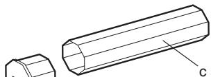
B Fully unroll the shutter (a). Remove the shutter material from the tube (b). Remove the manual control (c).
C Remove the tube.
D Push the motor (1) completely into the tube. The limit switch operates only if the drive unit is fully inserted. Ensure that the adapter ring is pushed fully home. Do not force it or strike it. Do not damage the tubular motor by drilling!
E Proceed according to the specific requirements for left-sided (a) or right-sided (b) operation:
F Secure the mounting bracket (8) to the wall (use suitable screws and plugs).
G Insert the motor (a) into the mounting bracket (8) and secure it.
Make sure the set screws for the limit adjustments are accessible.
Don't return the shutter material to the tube yet!
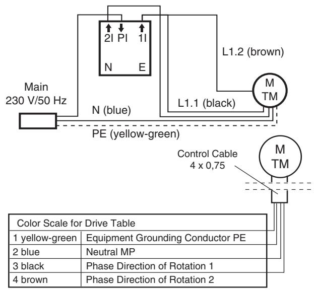
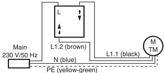
H ELECTRICAL CONNECTION

Never connect more than one motor to a timer or wall switch without using a central module - (h) (available as an accessory), i.e. one central module fired for each connected motor.
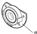
The illustration also shows the wall bracket on the drive side (b), the motor (a); the steel tube (c); the end cap (d); and the opposite wall bearing (e).
For a left-side motor installation, follow the wiring diagram exactly as shown in the control accessory package.
For the correct direction of rotation in a right-side motor installation, electrical wires (brown & black) must be reversed between the control accessory and the motor. (See instructions packed with the accessory you have chosen).
Have the electrical hook-up done by a qualified electrician in compliance with your local electrical code.
Accessories can be found in section L on page 4.
1
SETTING THE LIMITS
Procedure for Adjusting
"Open" and "Close" Positions
(refer to figure I for lefthanded installation)
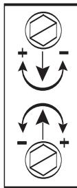
1 Limit Setting for "Shutter Open"
-
= increase travel
-
= decrease travel
2 Limit Setting for "Shutter Close"
-
= increase travel
-
= decrease travel

Please observe that the limits of the motor only operate in a complete installation.
Read the following instructions carefully before making any open or close limit adjustments.
To attach the shutter material on the tube, use ONLY the 3.9 × 6.5 mounting screws included (not suitable for RA10).
Otherwise, the drive might be damaged by screws which are too long.
This instruction applies particularly to model RA10 (no screws included). Use the appropriate fixing parts to secure the shutter material to the tube. The drive may be damaged by using screws which are too long.
IF ADJUSTMENTS ARE NEEDED, PROCEED AS FOLLOWS:
LIMIT ADJUSTMENT SCREW #1 - OPEN
Run the motor through an open cycle.
If motor stops before shutter is fully opened:
Turn set screw #1 toward + and open the shutter until desired position is reached.
If motor stops after shutter is fully opened:
- Close shutter below desired position. Turn set screw #1 toward - and open shutter again. Repeat this step as often as necessary to reach the desired position
LIMIT ADJUSTMENT SCREW #2 - CLOSE
Run the motor through a close cycle.
If motor stops too soon (before shutter is fully closed):
Turn set screw #2 toward + and close shutter again, until desired position is reached.
If motor stops after shutter is fully closed:
Retract shutter above desired position. Turn set screw #2 toward – and close shutter again. Repeat this step as often as necessary to reach the desired position.
TROUBLE SHOOTING
Motor does not run
- Public electricity supply failure. Check with a neighbor.
- Fuse has tripped or is blown. Check house overload protector. If necessary, have an authorized electrician redistribute the load.
- The switch is defective. Have it checked by an authorized electrician and replaced if necessary.
- Repeated operation may have tripped the motor overload protector switch. Wait 15 minutes and try again.
Motor runs intermittently
- Have the wiring connection between switch and motor checked by an authorized electrician. Replace if necessary.
Motor does not shut off
- Check to be sure tube adapter is positioned all the way up to the stop on the tube.
- Check to be sure the motor has been inserted all the way into the tube.
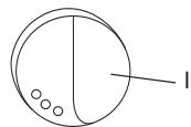
J
Leftsided Installation 703280
K
Connection of the
Model TCS1ED switch
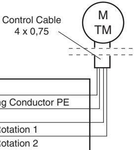
| Color Scale for Drive Table | |
| 1 yellow-green | Equipment Grounding Conductor PE |
| 2 blue | Neutral MP |
| 3 black | Phase Direction of Rotation 1 |
| 4 brown | Phase Direction of Rotation 2 |
L
No
Part
(a)
RA10
Description
RA20
Motor
10Nm/35mm
RA30
Motor
14Nm / 45mm
RA50
Motor
19Nm / 45mm
(b)
TAR40B
Motor
36Nm / 45mm
TAP65B
Adapter round, 40
TAO70B
Adapter profile, 65mm
TAM78B
Adapter octagonal, 70mm
TAM85B
Adapter awning, 78mm
(c)
TAM85B
Adapter awning, 85mm
(c)
WT840-2
Octagonal tube 40mm - 2m (40mm)
WT860-1
Octagonal tube 60mm - 1m
WT860-2
Octagonal tube 60mm - 2m
WT860-3
Octagonal tube 60mm - 3m
(d)
120995
Endcap for octagonal tube 60mm
(e)
121084
Opposite wallbearing for
(f)
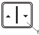
TCS1ED
Wall Switch (Rocker switch)
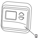
(g)
TCT2ED
Programmable Timer
TCTR2ED
Programmable Timer with integrated Receiver
TCTTX2ED
Programmable Timer with integrated Transmitter
(h)
WTMZ1
Central Module
(i)
TCRX3ED
Rolling Shutter Remote Control Receiver
(j)
TCTX2ED
Remote Control Wall Switch
TCRX2ED
Rolling Shutter Control with integrated Receiver
(k)
WTMLS1
Light Sensor
(1)
TCLS1ED
Remote Control Light and
Glass Breakage Sensor
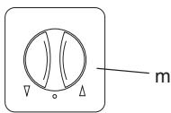
(m
703280
Switch - flush mount