
HC624ML - Automatic door motorization CHAMBERLAIN - Free user manual and instructions
Find the device manual for free HC624ML CHAMBERLAIN in PDF.
User questions about HC624ML CHAMBERLAIN
0 question about this device. Answer the ones you know or ask your own.
Ask a new question about this device
Download the instructions for your Automatic door motorization in PDF format for free! Find your manual HC624ML - CHAMBERLAIN and take your electronic device back in hand. On this page are published all the documents necessary for the use of your device. HC624ML by CHAMBERLAIN.
USER MANUAL HC624ML CHAMBERLAIN
Declaration of Conformity
Automatic Gate Opener Model HC624ML Series are in conformity to the applicable sections of StandardsEN300220-3 · EN55014 · EN61000-3 · EN60555, EN60335-1 · ETS 300 683 · EN60335-1: 2002 · EN60335-2-103: 2003 · EN55014-1: 2000 + A1 + A2 · EN55014-2: 2001 · EN61000-3-2: 2000 · EN61000-3-3: 1995 + A1 · EN 301 489-3, V1.3.1 · EN 300 220-3 V1.1.1 · EN13241-1
per the provisions & all amendments of the EU Directives 2006/95/EC, 2004/108/EC, 1999/5/EG
Declaration of Incorporation
Automatic Gate Opener Models, when installed and maintained according to all the Manufacturer's instructions in combination with a Gate, which has also been installed and maintained according to all the Manufacturer's instructions, meets the provisions of EU Directive 98/38/EC and all amendments.
I , the undersigned, hereby declare that the equipment specified above and any accessory listed in the manual conforms to the above Directives and Standards.
CE
AT/BA/BE/BG/CH/CY/CZ/DE/DK/ES/FR/GB/GR/HR/HU/IE/IS/IT/LU/MT/NL/NO/PL/PT/RO/RU/SE/SI/SK/TR/YU
www.chamberlain.de Email: info@chamberlain.de
B.P.Kelkhoff
Manager, Regulatory Affairs
Chamberlain GmbH
D-66793 Saarwellingen
July, 2008

Babba P. Kelchoff
IMPORTANT FITTING AND OPERATING INSTRUCTIONS
PLEASE START BY READING THESE IMPORTANT SAFETY RULES • SAVE THESE INSTRUCTIONS

This safety alert symbol means "Caution" - failure to comply with such an instruction involves risk of personal injury or damage to property. Please read these warnings carefully.
This gate drive mechanism is designed and tested to offer appropriately safe service provided it is installed and operated in strict accordance with the following safety rules.
Incorrect installation and/or failure to comply with the following instructions may result in serious personal injury or property damage.

When using tools and small parts to install or carry out repair work on a gate exercise caution and do not wear rings, watches or loose clothing.

Installation and wiring must be in compliance with your local building and electrical installation codes. Power cables must only be connected to a properly earthed supply.

Any entrapment possibility by the moving wing between wing & walls must be secured with safety edges or IR-sensors.

Please remove any locks fitted to the gate in order to prevent damage to the gate.

After the installation a final test of the full function of the system and the full function of the safety devices must be done.

This drive cannot be used with a gate incorporating a wicket door unless the drive cannot be operated with the wicket door open.

Frequently examine the installation for imbalance and signs of wear or damage to cables, hardware and mountings. Do not use if repair or adjustment is necessary. Gates which stick or jam must be repaired immediately. Employ a qualified technician to repair the gate, never attempt to repair it yourself.

Keep additional accessories away from children. Do not allow children to play with pushbuttons or remote controls. A gate can cause serious injuries as it closes.

Disconnect electric power to the system before making repairs or removing covers.
A disconnecting device must be provided in the permanently-wired installation to guarantee all-pole disconnection by means of a switch (at least 3mm contact gap) or by a separate fuse.

Make sure that people who install, maintain or operate the gate drive and/or the control board are qualified and follow these instructions.
Keep these instructions in a safe place so that you can refer to them quickly when you need to.

The full protection against potential squeeze or entrapment must work direct when the drive arms are installed.
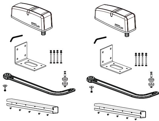
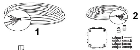
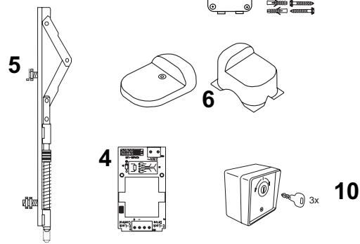
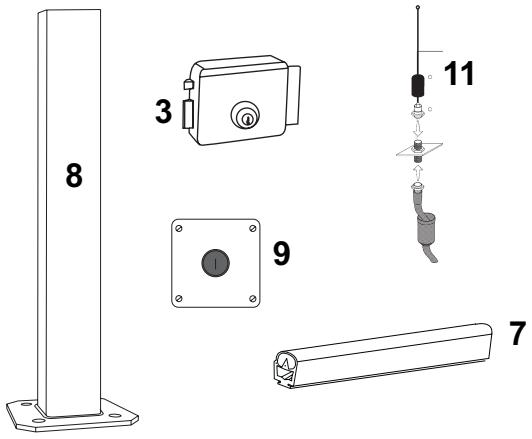
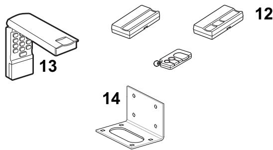
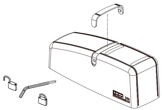
CARTON CONTENTS HC624
Drive motors 2x
Release key 2x
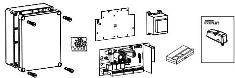
Box for control 1x
Cover for box 1x
Hinges for box 4x
Control 1x
Transformer 1x
Baseplate For Transformer 1x
Remote control 1-2x*
Radio receiver 1
Radio module 1x
Hardwarebag For Box 1x
Pillar fittings 2x
Gate fittings 2x
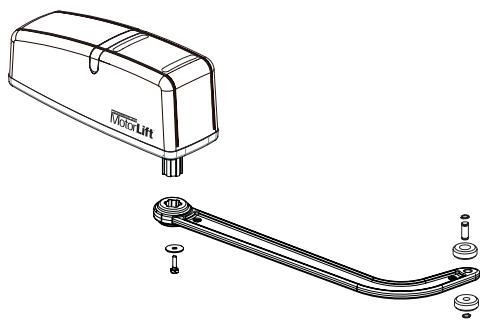
Door arm 2x
Hardwarebag 1x
Instructions 1x
1x
Key switch 1x
Photocells 1x
- depending on model resp. available as optional accessory


INSTALLATION CHECKLIST - PREPARATIONS
Check the carton contents and read the instructions carefully. Make sure your gate equipment operates perfectly. The gate must run evenly and smoothly and must not stick at any point. Remember that the ground level may be several centimeters higher in winter. The gate must be stable and as free of backlash in order to prevent any unwanted movement. The easier the gate movement the less power is needed by the motor.
Write down any materials you still need and obtain them before starting to install. Heavy-duty plugs, bolts, gate stops, cables, distribution boxes, tools, etc.
AVAILABLE INSTALLATION ACCESSORIES
- 041ASWG-0482-50 50m roll of installation cable, 6-pole for outdoor use, Laying possible without cable duct with the identical wire colours as motor
- LA400-JB40E Kit for cable extension of one installation unit. Consists of 12m of cable 6-pole with identical colours, distribution box IP65, cable screw joints and fastening material
- E-lock 203285 (12Volts)
- Transformer for E-lock 207399
- Floor locking 203339 (in combination with E-lock)
- Stops for wings 203315 (standard) and 203322 (high)
- Safety edge 600046 2.5m set of safety edge (profile & rail) 600053 20m of rubber profile (small) 600077 20m of mounting rail 600077-1 2m of mounting rail 600060 Assembly pack is required for each safety edge
- IR Sensor stand 600008 single, height 530mm
- Emergency Stop switch 600084 plastic enclosure, IP65
- Keyswitch 100034 2-Function, flush-mount 100041 2-Function, surface-mount
- External Antenna 041ASWG-ANT
- Remote Controls 84330EML 1-channel
84333EML 3-channel
84335EML 3-channel, mini - Wireless keypad 8747EML
- Base plate standard ART-7
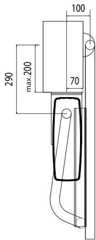
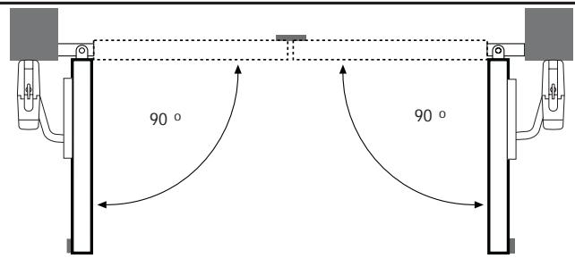
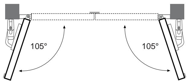
BEFORE YOU BEGIN: The HC624 is suitable for use with wide pillars, up to about 29cm in width. Width of doorwing must comply with chart. The maximum recommended opening angle of the gate is 105 degrees. Ensure that ample space is available next to the drive for the arms and assembly. Gates exposed to a high wind load must be fixed with an electric lock for additional protection. Gate stops must be installed There are many important factors when deciding on the correct motor. Assuming a well functioning gate, the initial force is the most difficult moment. When the gate is moving it generally requires a considerably smaller amount of force.
Gate Size: Gate size is an important factor. Wind can slow down gate or distort it, leading to higher amount of required force.
Gate weight: Specification of gate weight represents only a rough parameter, which can vary according to actual demand. Operation is important.
Influence of temperature: Low outdoor temperatures can impede or even prevent starting torque (ground deformation etc.). High outdoor temperatures can lead to premature initiation of temperature protection (approx. 135^ )
Attention: Motors are not designed to run continuously (continuous operation). The motor warms up and can reach a temperature at which it shuts down until operating temperature is reached again. Outside temperature and gate represent important parameters for actual operating duration.
TECHNICAL DATA:
Motor voltage 24V
Nominal power 10W
Max. power
Current nom.
Current max.
Torque max.
Opening time 90^
Cycles/h
Consecutive cycles max.
Operating temperature
Degree of protection
Weight
24V
10W
40W
0,5A
1.3A
200Nm
16 sec.
\~20
8
-20°C - +55°C
IP44
8kg
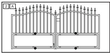
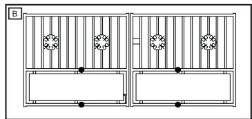
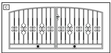
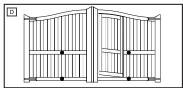
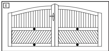
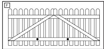
GATE TYPES
The location of the motor installation depends on the type of gate. If the gate stop is on the floor the motor should also be installed as low as possible in order for the gate not to be distorted. Only use frame elements for fastening. With steel gates the fittings should be fastened to the main frame. If you are not sure about the stability of the frame in question then reinforce it.
With wooden gates the frame has to be drilled through completely where the fittings are to be fastened. Attaching a plate from the outside is recommended in order to prevent fastening from becoming loose. Thin wooden gates must be reinforced additionally as they do not withstand the strain otherwise.
Max gate width/weight
2,5m per wing / 150Kg
2,0m per wing / 200Kg
1,5m per wing / 250Kg
Max gate height
1,5m
Specifications calculated without windload
GATE CONFIGURATION
The ART is suitable for use with wide pillars, up to about 29cm in width. The amount of room around the pier affects the opening angle and the position of the arms.
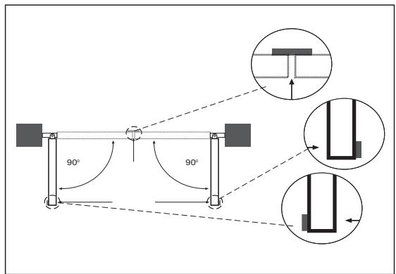
GATE STOPS
A SWING GATE NEEDS A FIXED GATE STOP IN BOTH THE OPEN AND CLOSE POSITIONS. Gate stops save wear and tear on the motor, gate and fittings. Operating a gate without fixed limit stops results in poor performance. It is often dangerous, leads to premature wear and voids your warranty!
GATE FITTING
With steel gate the fastenings should either be welded on or drilled through completely. If drilling then attach large washers or a plate to the back of the frame. With wooden gates the gate frame has to be drilled through completely where the fittings are to be fastened. Attach reinforcement plate on the outside and inside of the gate in order to prevent wood from giving and the connection to become loose.
Thin wooden gates without metal frame must be reinforced additionally, as they do not withstand the strain otherwise. Before installing the gate fitting, check if you measured the right position for it. Adjust if needed.
Attach gate fitting with a c-clamp or mark its designated position. To compare, open the gate to designated OPEN position. Now finally mont gate fitting.
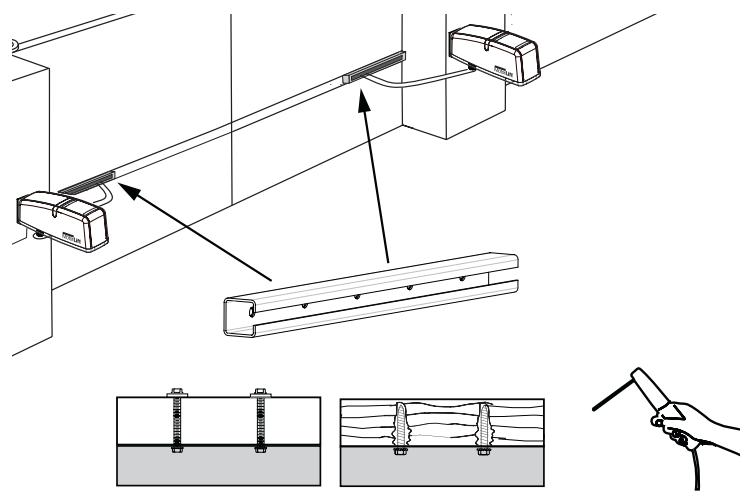
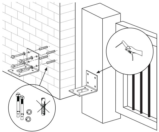
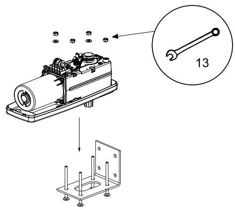
BASE PLATE
Select and mark the mounting height on the pier. Finding the right mounting position. Mount the drive on the pier and attach it to the gate. The drive exerts a great amount of force on the pier. A steel pier will provide the most stability. Welding the supplied hinge plate directly on to the pier will generally provide enough room for mount. In the case of thick brick or concrete pillars, the hinge plate should be welded onto a support plate, that is mounted in such a way that the plugs cannot work loose. Adhesive shear connectors are better than steel or plastic wedge anchors for this purpose. A threaded rod is then mounted into the masonry with a stress free adhesive seal. A watertight distribution unit should be mounted on the pier next to the hinge plate. The feed cable for the wing gate opener is led into this unit from underneath.
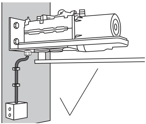
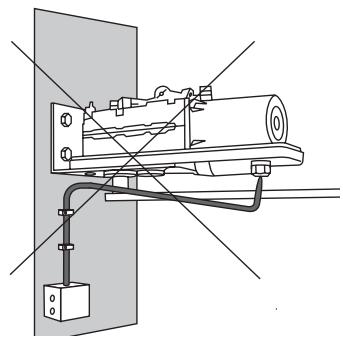
Mount operator and run cable the right way
Once the base plate has been mounted, the drive can then be fitted. The drives can be used left or right without requiring conversion. For the purposes of fitting the drive, the lock screws need to be re-inserted and tightened up.
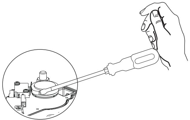
Several openings for the cable have been pre-punched in the base and need only be broken through, as required. The drive must be standing on a solid surface for the purposes of breaking the holes through to prevent the PVC base plate from breaking. A small, flat screwdriver should be used for breaking the holes through. For this purpose, tap on the screwdriver handle with the palm of the hand from the inside. Repeat this as necessary at several points on the pre-marked circle. The pre-punched area can then be easily removed and the strain relief supplied as standard fitted in its place.
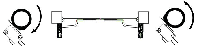
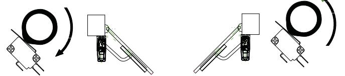
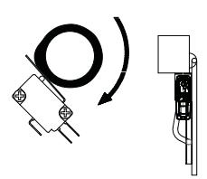
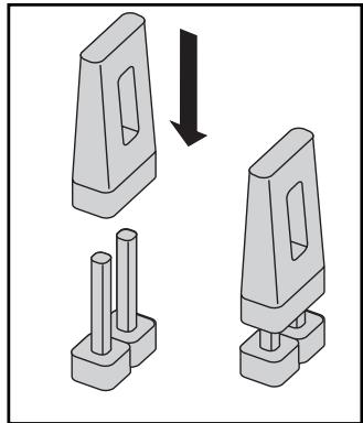
SWITCHES, CAMS AND RIGHT ADJUSTMENT
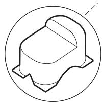
There is a small switch operated by a cam under the operator's cover. The cam rotates simultaneously to the operator and pushes the switch temporarily. The cam can be adjusted (rotated). (Tight) Deinstallation is not required.
Use pliers or a big screwdriver to adjust (see picture).
RIGHT ADJUSTMENT
Gate closed:
switch free
Gate at approx. 45^
switch fully pushed (cam operates switch)
Gate open:
switch free

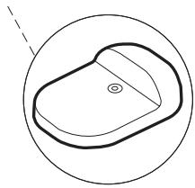
The release lock for the casing is located under the rubber waterproof cover. Use the socket spanner supplied in the hardware bag to lift the cover up. The release key located beneath the hood should be inserted into the side openings and turned approx. 180 degrees until it cannot turn any further. The drive has now been released. To reengage it, the key should be turned back to its original position.
Take care when unlatching the drive for manual operation. The door leaf can move in an uncontrolled way, especially if it is defective and not properly balanced.
Before initial operation check if operator does not come in contact with the gate in the fully OPEN position.
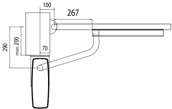
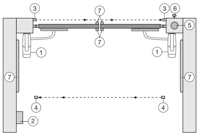
TYPICAL CONFIGURATION OF A UNIT:
- Motor
- Control board
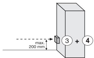
- Photocell (active for closing), max. height 200 mm First photocell.
- photocell (active for opening and closing), max. height 200 mm Second photocell (optional).
- Flashing light (optional)
Important visual information on the movement of the gate.
- Key-operated switch or wireless keypad (optional) Is mounted on the outside. The gate is opened by key or by entering a number.
- Contact strip (optional) Safeguards the gate on being touched. Contact strips can be mounted on the gate or on the pillars. If required, contact strips must be mounted at a height of up to 2.5m .

The control board complies with the latest EU
guidelines. One of these guidelines specifies that the
closing forces at the gate edge must not exceed 400N (40 kg) for the last 500 mm before the door is CLOSED. Above 500 mm, the maximum force at the gate edge must not exceed 1400 N (140 kg). If this cannot be ensured, a contact strip must be mounted on the gate at a height up to 2.5 m or on the pillar on the opposite side (EN12453).
Note: The listed accessories on page 2 are especially suited for the professional installation of a gate system.
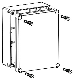
INSTALLATION OF CONTROL BOX
The control consists of several components which are fitted together and are screwed into the box. Precision is important.
Complete the electrical installation (wiring, supply etc.) before turning your attention to this point.
Find the following parts in the control box:
| - Remote control | 1-2x* |
| - Exterior installation box | 1 |
| - Cover for box | 1 |
| - Control | 1 |
| - Transformer | 1 |
| - Baseplate for transformer | 1 |
| - Radio receiver | 1 |
| - Radio module | 1 |
| - Cable bushing large | 1 |
| - Cable bushing small | 1 |
| - Flat washer | 5 |
| - Screws 3,5x 9,5 mm | 17 |
- depending on model resp. available as optional accessory
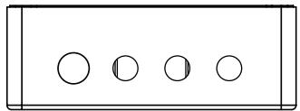
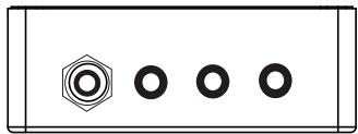
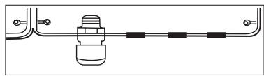
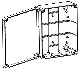
PREPARING THE CONTROL BOX
Open the 4 pre-cut holes at the bottom of the casing with a screwdriver or a similar device.
Attach large cable bushing on the left then the rest as shown in picture.
Humidity and water destroy the control. All openings and cable bushings must be sealed against water (waterproof). The control box with the motor control is to be mounted with the cable bushings facing down.
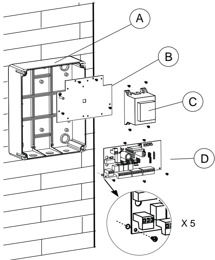
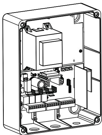
RECOMMENDED PROCEDURE:
A. Fasten control box of casing to wall, after previously measuring required distances and establishing correct position of drill-holes. (Hardware not included)
B. Fasten baseplate for transformer in casing. (Screws 3.5 × 9.5 ~mm )
C. Fasten transformer on to baseplate; do this using 4 screws (Screws 3.5 × 9.5 ~mm ). On the right hand side of transformer there is sufficient space for a second transformer (Screws 3.5 × 9.5 ~mm ), which can control locking of a 12Volts E Lock. (accessories).
Attach short earthing cable (yellow/green) to the plate using a screw and a washer.
D. Attach logic board underneath baseplate; do this using 5 screws and fasten in the box at the marked positions. Before that pull all plug ins from their sockets. A small bag contains jumpers for the control. These might be needed later on individual settings in the controls' programming. (refer to JUMPERS)
Put the 4 large closure screws of the box through cover of the box. Fasten 2 of them (left or right) approx 2cm into the box. After that the cover may be opened to the side.
Close box on a trial basis turning the screws all the way in. If the lid does not close completely, then the box is not fitted to the wall evenly and is therefore distorted. This must be corrected. It is very important for the box to be waterproof once closed.
TECHNICAL DATA OF MOTOR CONTROL:
Voltage
Transformer
Output motor
Supply accessories
Operating temperature
Degree of protection
230VAC
230/24VAC minimum60VA
24VDC max.
24VDC - 100mA
-20°C - +55°C
IP54
WIRING OF CONTROL / SUMMARY
a) start with still dead 230Volts supply cable on the left side of the box.
b) Attach cable eye to ground wire. Then connect ground wire to base plate with washer and nut (exactly as shown in picture detail).
Connect all other cables to control.
Attention:Check repeatedly that cable colours are connected correctly to motor. Otherwise motor might be damaged or will not operate properly. Pay special attention when using distribution boxes.
We recommend the following accessories: LA400-JB40E Kit for cable extension of one installation unit. Consists of 12m of cable 6-pole with identical colours, distribution box IP65,cable screw joints and fastening material
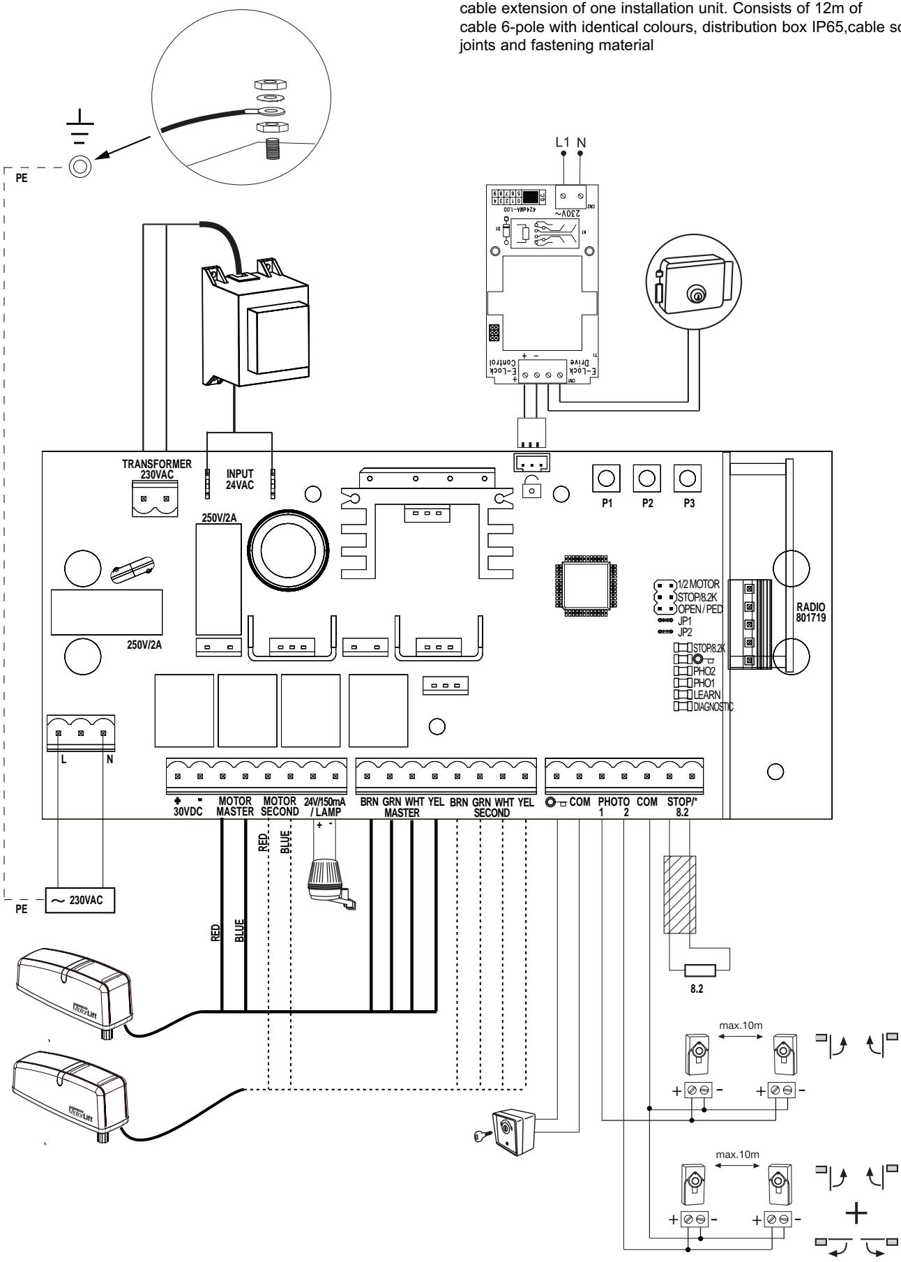
| DESCRIPTION | FUNCTION | |
| L | Connector L 230V supply | |
| N | Connector N 230V supply | |
| Battery | Connector for a battery kit +/- 475E + 041ADBL-0115 | |
| Motor MASTER | motor 1 (master opens first) | |
| Motor SECOND | motor 2 (Second opens second) | |
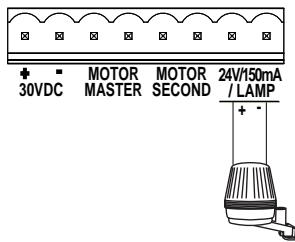
| 24V/150mA | Flashing light (accessory) | |
| MASTER | Motor1 | |
| BRN | brown cable | |
| GRN | green cable | |
| WHT | white cable | |
| YEL | yellow cable | |
| SECOND | Motor2 | |
| BRN | brown cable | |
| GRN | green cable | |
| WHT | white cable | |
| YEL | yellow cable | |
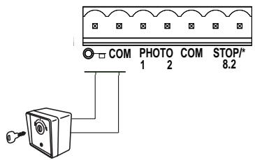
| “Key symbol” | key switch | |
| COM | negative pole | |
| PHOTO1 | Photocells 1 | |
| PHOTO2 | Photocells 2 | |
| COM | negative pole | |
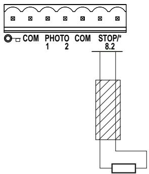
| STOP 8.2KOhms | connector for emergency switch or safety edge with 8.2KOhms | |
| RADIO | connection for 801719 radio receiver | |
| E-lock symbol | connection for E-lock control board | |
| INPUT 24VAC | 24V power input from transformer. Can be connected with any polarity. | |
| Transformer 230VAC | 230V supply to transformer. Can be connected with any polarity. | |
| 250V/2A | Fuse 250V/2A (2x included) | |
| DESCRIPTION OF PUSH BUTTONS | ||
| P1 button to program “simple” mode P2 button to program “individual” mode P3 button to program “Timer to close” | ||
| Description of LED's (light-emitting diode) | ||
| Description | Colour | Function |
| STOP/8.2KOhms | green | monitors emergency switch or safety edge ON: blocks control board OFF: OK |
| “Key symbol” | red | key switch ON: key switch is operating OFF: key switch is not operating |
| PHO2 | red | Photocells 2 ON: OK (active) OFF: no photocell fitted |
| PHO1 | red | Photocells 1 ON: OK (active) OFF: no photocell fitted |
| LEARN | yellow | learn mode indication ON: learn mode active OFF: learn mode inactive |
| DIAGNOSTIC | red | diagnosis mode Refer to FAQ's |
Only modify settings when control bord is disconnected. Otherwise modifications will not be accepted!!!
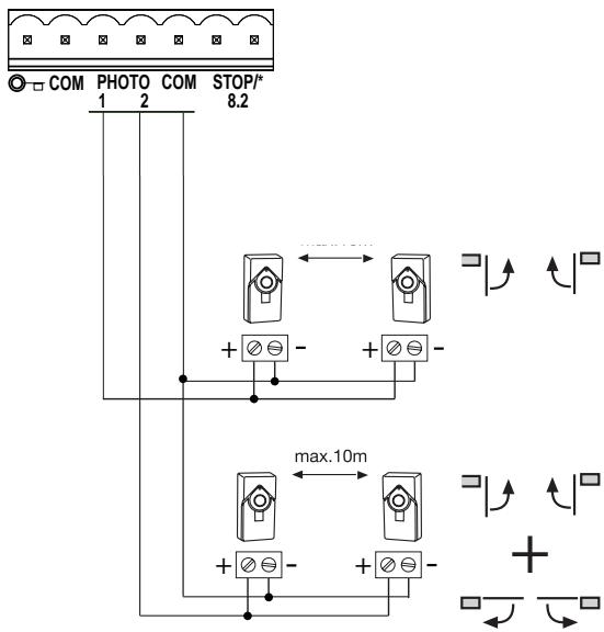
PHOTOCELLS (OPTIONAL)
The photocells are for safeguarding the gate and must be used. The fitting location depends on the gate's design. EN12453 specifies that a pair of photocells must be installed at a height of 200mm and activated to "Close". The photocells consist of a transmitter and a receiver and must be opposite each other. The photocell is mounted on the wall using small screws and wall plugs. To enable the "Automatic Closing" function, the Chamberlain fails safe photocell must be installed. The Chamberlain fails safe system (2-cable system) has small LEDs (light) that can be seen from the outside on both sides to indicate the status of the photocell.
Diagnosis at the Chamberlain fails safe photocell
LED constant = OK
LED flashes = photocell disables control board
LED off = no current, incorrect connection or polarity
Diagnosis on the control board
LED off = OK no photocell connected
LED on constantly = OK
LED flashes = photocell disables control board
Connection between 1 & COM will give:
ignored when gate is opening, when closing if beam is blocked gate stops then reopens (does not matter when beam is unblocked).
Connection between 2 & COM will give:
when gate is opening block beam gate stops when you un-block beam gate caries on opening.
When gate is closing block beam gate stops un-block beam gate reopens.
KEY SWITCH (OPTIONAL)
The system can be operated by key switch. It is possible to operate only 1 wing or two wings. This depends on how the JUMPERS are used (connectors: key symbol and COM)
SAFETY EDGE (OPTIONAL)
A safety edge working according to the 8.2 kilo ohm principle can be connected to the control board, i.e. a 8.2 kilo ohm test resistor is attached to the end of the safety edge. It ensures that the electric circuit is monitored permanently. The control board is supplied with an 8.2 kilo ohm resistor installed. Several safety edges are connected in series.
Cable cross-section: 0.5mm^2 or more.
8.2
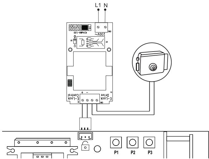
E-LOCK (OPTIONAL)
The control board allows the use of a 12V E-lock. (instructions included with E-lock).
A support board must be connected for the E-lock on the main board.
Attach support board next to the transformer on to the baseplate using screws.
Open its casing and make all necessary electrical wiring.
Plug support board in to where the E-lock symbol is depicted.
FLASHING LAMP (OPTIONAL)
A flashing lamp can be connected to the control board. It warns when the gate is being moved. The flashing light should be fitted as high as possible and in good clear view. The control board emits a constant signal that the lamp converts to a flashing signal.
Cable cross-section: 0.5mm^2 or more.
Voltage: 24 V DC

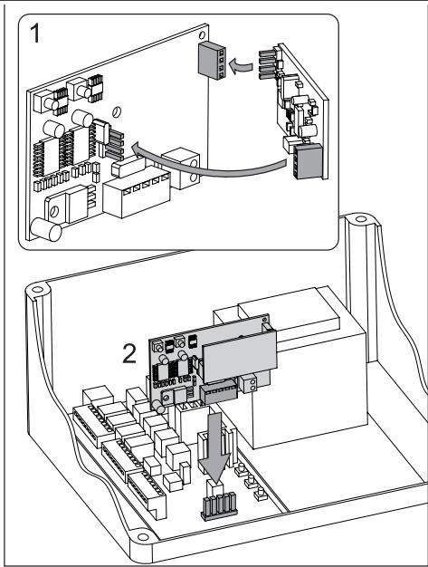
RADIO
There are two small cartons. One of the cartons contains the receiver, which stores remote control codes. The other one contains the radio module, which receives the radio signal.
- connect the smaller radio module with the receiver Make sure all pins are properly engaged
- connect the receiver with the control board Antenna: The receiver includes a short antenna. It should not come in contact with any cable and should not be rolled up. It is possible to install an external antenna which enlarges the operating distance of the remote control (optional accessory).
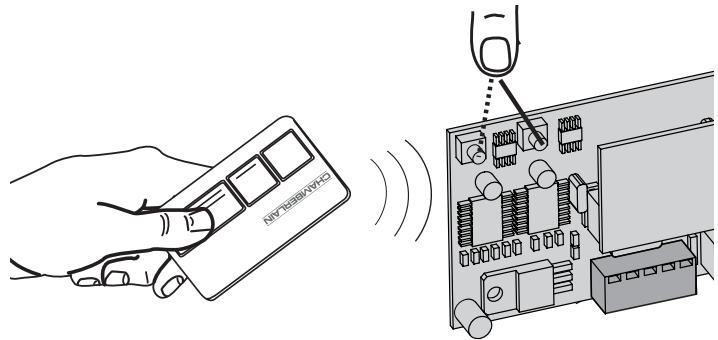
PROGRAM / DELETE REMOTE CONTROLS
The receiver has two channels CH1 and CH2. Using the different channels enables the opening of one wing resp. both wings. For example, if CH1 receives the code from the remote control only one wing will open. Choosing a different button on the remote control in combination with CH2 will cause both wings to open.
In order to store a code press a previously selected button on the remote control while simultaneously pressing the learn Buttons CH1 or CH2 of the receiver. Repeat for all remote controls.
A maximum of 12 remote controls can be programmed to each channel.
Note: Make sure not to pogramm the same remote button to CH1 and CH2, otherwise the gate may work improperly. Redo programming if required.
DELETE
Press learn Buttons (CH1 or CH2) for approx. 10 seconds until LED goes out. All codes programmed to this channel are deleted.
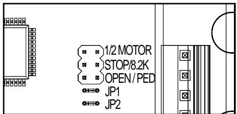
JUMPERS
1/2 Motor
1 or 2 motors are connected to the control board.
FREE: both motors connected
LINKED: only one motor connected
STOP / 8.2 KOhms
Defines if connector STOP / 8.2 KOhms is used for an emergency stop switch or for a safety edge. The emergency stop switch stops any movement of the system immediately. The safety edge causes the wings to reverse for one second.
FREE: Factory setting is for 8.2 KOhms. In this case safety edge must be installed or a 8.2 KOhms resistor must be connected.
LINKED: used for emergency stop switch, in this case the pre-installed resistor has to be removed from terminals and replaced by a suitable switch or terminals have to be bridged.
Open / Ped
Defines if key switch operates only one wing (Master) or both wings FREE: only one wing (Master)
LINKED: both wings
Proceed step by step. If you are not sure, start again at the beginning. Take sufficient time to make these settings.
- Are all components required for operation connected? Motors, photocells, safety contact strip, stop switch.
- Make sure that nobody is present in the range of the gates.
- Check/Adjustment/Correction of cams on both motors
Gate closed: switch free
Gate at approx. 45^ : switch fully pushed (cam operates switch)
Gate open: switch free
(for adjustment refer to mechanical installation)
BASIC SETTING:
- Press buttons P1, P2 and P3 simultaneously for approx. 2-3 seconds until yellow LED flashes.
- Monitor the gate. Press and hold P1 for 1-2 seconds. The wing with motor 1 opens. If motor 1 closes, it is wired incorrectly and the red and blue wires of the motor cable must be inverted. (Caution: Disconnect Power!) Repeat steps 1 and 2. Leave gate/s in partially open position.
NOTE: General operation – if you release the button, the gate will immediately stop. By pressing the button again the gate will move in the opposite direction until you release the button, and so on.
3. Press and hold P2 for 1-2 seconds. The wing with motor 2 must open. (Do not open gate completely, only short distances.) If motor 2 closes, it is wired incorrectly and the red and blue wires of the motor cable must be inverted.
(Caution: Disconnect Power!)
Repeat steps 1 and 2. Leave gate/s in partially open position.
NOTE: The control board is active for this manual setting mode for approx. 20 seconds. If necessary, start again by pressing P1, P2 and P3 simultaneously.
Now check the following:
- If both operators connected open both wings completely.
- Both wings must open completely. Do not open the wings too far! A gate stop in OPEN position is required.
Caution: Gate must not come in contact with operator (i.e. when operator has been released for manual operation) Wait until learn-LED goes out (20 seconds after a button was pressed).
PROGRAMMING TRAVEL DISTANCES "SIMPLE I"
NOTE: only with stops in OPEN and CLOSE position
- Wings must be closed
- Press P1 until wing / motor 1 starts opening (learn-LED flashes resp. glows)
Automatic programming starts (slow travel)
Wing 1 moves to the stop in OPEN position
Wing 2 moves to the stop in OPEN position
Then wing 2 moves to the stop in CLOSE position.
Then wing 1 moves to the stop in CLOSE position.
When the learn-LED goes out the programming has finished.
PROGRAMMING TRAVEL DISTANCES "ADVANCED"
NOTE: In this mode P1 must be pressed 9 times. With every time the button is pressed a position (time) is stored. (This allows programming of SOFT-STOP (slow travel) in order to adjust to application. Long or short phases of SOFT-STOP are possible.
- Both wings must be closed.
- Press P1 and P2 for approx.5-6 seconds until wing / motor 1 starts opening. Release buttons!!!
- Press P1 again. SOFT-STOP for wing / motor 1 in OPEN direction starts at this point.
- Press P1 again when OPEN position is reached.Now wing / motor 2 starts automatically to open.
- Press P1 again. SOFT-STOP for wing / motor 2 in OPEN direction begins at this point.
- Press P1 again when OPEN position is reached. Now wing / motor 2 starts closing automatically.
- Press P1 again. SOFT-STOP for wing / motor 2 in CLOSE direction begins at this point.
- Press P1 again when CLOSE position is reached. Now wing / motor 1 starts automatically to close.
- Press P1 again. SOFT-STOP for wing / motor 1 in CLOSE direction begins at this point.
- Press P1 again when CLOSE position is reached. Done!
NOTE: If one wing reaches a stop and button P1 is not pressed, then the motor moves towards the stop and stores this position automatically.
COMPLETION OF INSTALLATION / PROGRAMMING
Once the travel distances are programmed, the remote controls can be programmed as well.
(Refer to PROGRAMM / DELETE REMOTE CONTROLS).
- Operate the gate with a remote control or with a connected switch and monitor the direction. Close the gate again WITHOUT any interruptions.
- If all adjustments are done, check operation of photocells, switch, flashing light, remotes, accessories, etc.
- Advise people using the gate with regard to gate operation, safety functions and how to release the gate in order to operate it manually.
TIMER TO CLOSE
NOTE: Only possible with connected photocells (1 + COM). Time frames from 2 seconds up to 120 seconds are possible.
Activate:
- Press and hold P2 until yellow LED starts flashing
- Now count the time you wish to program
- Press P2 again. Done!
Deactivate:
- Press and hold P2 until yellow LED starts flashing.
- Press P3. Yellow LED goes out. Done!
TORQUE OF MOTOR
Thrust of the motor is set automatically while programming the travel distance. Thrust can only be modified by programming the travel distance again. If gate movement is impeded by weather or changes to the installation (rust or inappropriate lubrication) it may have to be repaired.
The control board complies with the latest EU guidelines. One of these guidelines specifies that the closing forces at the gate edge must not exceed 400N (40 kg) for the last 500 mm before the door is CLOSED. Above 500 mm, the maximum force at the gate edge must not exceed 1400 N (140 kg). If this cannot be ensured, a contact strip must be mounted on the gate at a height up to 2.5 m or on the pillar on the opposite side (EN12453).
INDICATION OF THE DIAGNOSIS LED
| Indication | Description | Remedy |
| 1x blinking | Motor 1 has insufficient connection to control board | Green or white cable not wired or badly connected Check terminals precisely. Consider wire lengths |
| 2x blinking | Motor 2 has insufficient connection to control board | Refer to 1x blinking |
| 3x blinking | Limits for motor 2 have not been acceptedA: After or during first travel: operator did not open open wide enough to meet not meet passport (cam did not operate switch) | A: Open gate wide enough when programming the travel. Make sure cam passes all 3 states (switch free, pushed, free)B: Check terminals precisely. Consider wire lengths |
| B: Motorcables have insufficient connection to control boardYellow or white cable not wired or badly connected | ||
| 4x blinking | Limits for motor 1 have not been accepted | Refer to 3x blinking |
| 5x blinking | Travel has not been programmedThe process of programming has been interrupted | Repeat programming travel |
| 6x blinking | Force to operate the gate is too highA: Gate is out of orderB: Gate is rough-runningC: Gate stopped through windload | A: Repair gateB: Check if gate can be easily movedC: Do not operate gate by windstormD: Reprogram travel to achieve sufficient level of fo |
| 7x blinking | Photocells 1 block installationA: Object blocks photocellsB: Alignment of the lenses is incorrectC: Power supply to photocells is insufficient | A: Remove objectB: Check alignmentC: Check cable widths and contacts |
| 8x blinking | Photocells 2 block installation | Refer to 7x blinking |
| 9x blinking | Emergency stop switch blocks installation | A: Check wiringB: Check basic setting of control board (Jumper) |
| 10xblinking | Safety edge blocks installationA: Object obstructs safety edgeB: Defective safety edgeC: Power too low or broken wire in supply | A: Remove objectB: Check wiring. Check resistor 8.2KOhmsC: Check basic setting of control board (Jumper) |
| 11xblinking | Power supply to control board is too lowA: Defective supply 230V or malfunctioning contactB: Broken wire in supply cable (copper cable)C: The battery (accessory) to operate the gate whilst power failure is dead. | A: Check electric contactB: Check by electricianC: Allow battery to charge 24 hours |
| 12xblinking | EEPROM FaultPower up failed | Replace control board |
FAQs
| The gate opener doesn't respond at all; no LED is on. | Possibly power failure. | 1. Check conductor and zero conductor. 2. Check house fusing. |
| Immediately after the gate has started moving, it stops and reverses. | Obstacle in area of gate. | Check area of gate for objects If there is no obstacle, make another initial operation to ensure the force will be learned again. |
| The gate opener does not open the gate fully. | 1. Are the post dimensions A+B correct? 2. Has the travel of the controller been set correctly? | 1. Check A+B dimensions. 2. Reprogram if required |
| Gate can only be opened | 1.photocell blocks | 1.Function and connection must be checked |
| “Timer to close” doesn’t work. | 1. Only works if the 2-cable photocell 770E(ML) or 771E(ML) has been installed. | |
| The control board does not work any more using the transmitter, only with the switch and even then only as long as a button is pressed and kept pressed. | A safety photocell, a contact strip or the stop disables the control board Only one photocell was connected for OPEN | At least one photocell must be connected and activated for CLOSED or OPEN. |
| The gate opener doesn’t respond at all, although the controller has been connected (LEDs are on). | 1. Remote control has not been programmed. 2. LEDs indicate a fault. 3. Photocell connected incorrectly. 4. Motor terminal possibly not connected properly. | 1. Programming remote control. 2. Find and rectify fault(s) (see description of LEDs). 3. Check photocell connection / programming. 4. Check terminals and connections. |
| Control board does not work with transmitter | 1.transmitter not programmed 2.An photocell blocks | 1.Program transmitter 2.Checked cells |
| The control board is not running | No travel has been learned | Learn travel. See Initial operation |
| The wings do not open completely. | 1.Insufficient force in the event of high wind loads (entire gates) 2.Gate sluggish/heavy | 1 Reset force (increase) 2. Improve ease of movement 3.Program control board again |
| The remote control's range is too short. | The installation of an external aerial is recommended as the controller with the short cable aerial is located either behind the post or near ground level in most cases. The optimum location of the aerial is as high as possible in all cases. An appropriate aerial with installation kit can be obtained from Chamberlain as an accessory with the product ref. no. ANT4X-1LM. | |
| The gate must follow a slope. | Not recommended! Change gate! The gate can move in an uncontrolled (dangerous) manner if the gate opener has been released. A stronger force is needed in the upwards direction of the slope and then, in the opposite direction, the gate opener's force is too strong. | |
The gate post is so thick that I am unable to comply with the requisite A+B dimensions.
Reduce post thickness or shift gate location.