USER MANUAL HC300ML CHAMBERLAIN
CHAMBERLAIN™ MotorLift™

Instruction and electrical set up HC280ML,HC300ML/MLS,HC400ML/MLS,HC600ML/MLS

Istruzione e installmente elettrica HC280ML,HC300ML/MLS,HC400ML/MLS,HC600ML/MLS

Instruktie en electrische installment HC280ML,HC300ML/MLS,HC400ML/MLS,HC600ML/MLS

Instrucciones y instalacion electrica HC280ML,HC300ML/MLS,HC400ML/MLS,HC600ML/MLS
www.chamberlain.com E-mail: info@chamberlain.com
Manager, Regulatory Affairs
Chamberlain GmbH
D-66793 Saarwellingen
lanuar,2006

INSTRUCTIONS IMPORTANTES POUR LE MONTAGE ET L'UTILISATION
VEUILLEZ TOUT D'ABORD LIRE CES REGLES DE SECURITE IMPORTANTES


Tension: 12/24 Volt CA/CC.
ARRET D'URGENCE (OPTION)
BARRE PALPEUSE (OPTION)
ANTENNE (OPTION) ANT4X-1EML
Manager, Regulatory Affairs
Chamberlain GmbH
D-66793 Saarwellingen
Januar, 2006

Dabbaia P. Keckhoft
IMPORTANT FITTING AND OPERATING INSTRUCTIONS
PLEASE START BY READING THESE IMPORTANT SAFETY RULES • SAVE THESE INSTRUCTIONS

This safety alert symbol means "Caution" - failure to comply with such an instruction involves risk of personal injury or damage to property. Please read these warnings carefully.
This gate drive mechanism is designed and tested to offer appropriately safe service provided it is installed and operated in strict accordance with the following safety rules. Incorrect installation and/or failure to comply with the following instructions may result in serious personal injury or property damage.

When using tools and small parts to install or carry out repair work on a gate exercise caution and do not wear rings, watches or loose clothing.

It is important to make sure that the gate always runs smoothly. Gates which stick or jam must be repaired immediately. Employ a qualified technician to repair the gate, never attempt to repair it yourself.

Installation and wiring must be in compliance with your local building and electrical installation codes. Power cables must only be connected to a properly earthed supply.

Keep additional accessories away from children. Do not allow children to play with pushbuttons or remote controls. A gate can cause serious injuries as it closes.

Any entrapment possibility by the moving wing between wing & walls must be secured with safety edges or IR-sensors.

Disconnect electric power to the system before making repairs or removing covers.

Please remove any locks fitted to the gate in order to prevent damage to the gate.
A disconnecting device must be provided in the permanently-wired installation to guarantee all-pole disconnection by means of a switch (at least 3mm contact gap) or by a separate fuse.

After the installation a final test of the full function of the system and the full function of the safety devices must be done.

Make sure that people who install, maintain or operate the gate drive follow these instructions. Keep these instructions in a safe place so that you can refer to them quickly when you need to.

This drive cannot be used with a gate incorporating a wicket door unless the drive cannot be operated with the wicket door open.

The full protection against potential squeeze or entrappment must work direct when the drive arms are installed.
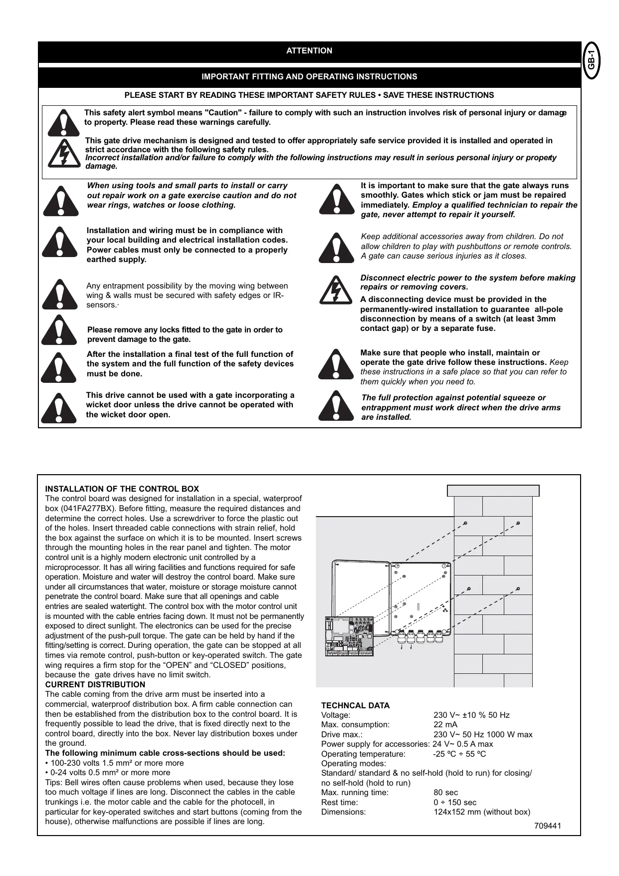
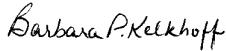
INSTALLATION OF THE CONTROL BOX
The control board was designed for installation in a special, waterproof box (041FA277BX). Before fitting, measure the required distances and determine the correct holes. Use a screwdriver to force the plastic out of the holes. Insert threaded cable connections with strain relief, hold the box against the surface on which it is to be mounted. Insert screws through the mounting holes in the rear panel and tighten. The motor control unit is a highly modern electronic unit controlled by a microprocessor. It has all wiring facilities and functions required for safe operation. Moisture and water will destroy the control board. Make sure under all circumstances that water, moisture or storage moisture cannot penetrate the control board. Make sure that all openings and cable entries are sealed watertight. The control box with the motor control unit is mounted with the cable entries facing down. It must not be permanently exposed to direct sunlight. The electronics can be used for the precise adjustment of the push-pull torque. The gate can be held by hand if the fitting/setting is correct. During operation, the gate can be stopped at all times via remote control, push-button or key-operated switch. The gate wing requires a firm stop for the "OPEN" and "CLOSED" positions, because the gate drives have no limit switch.
CURRENT DISTRIBUTION
The cable coming from the drive arm must be inserted into a commercial, waterproof distribution box. A firm cable connection can then be established from the distribution box to the control board. It is frequently possible to lead the drive, that is fixed directly next to the control board, directly into the box. Never lay distribution boxes under the ground.
The following minimum cable cross-sections should be used:
100-230 volts 1.5mm^2 or more more
- 0-24 volts 0.5 mm^2 or more more
Tips: Bell wires often cause problems when used, because they lose too much voltage if lines are long. Disconnect the cables in the cable trunkings i.e. the motor cable and the cable for the photocell, in particular for key-operated switches and start buttons (coming from the house), otherwise malfunctions are possible if lines are long.
TECHNICAL DATA
Voltage: 230 V~ ±10 % 50 Hz
Max. consumption: 22 mA
Drive max.: 230 V~50 Hz 1000 W max
Power supply for accessories: 24V 0.5A max
Operating temperature: -25 °C ÷ 55 °C
Operating modes:
Standard/ standard & no self-hold (hold to run) for closing/
no self-hold (hold to run)
Max. running time: 80 sec
Rest time: 0 ÷ 150 sec
Dimensions: 124x152 mm (without box)
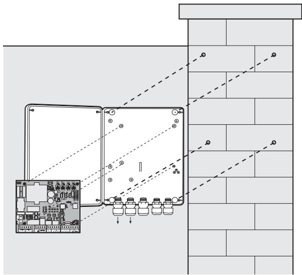
Typical configuration of a unit:
- Motor
- Control board
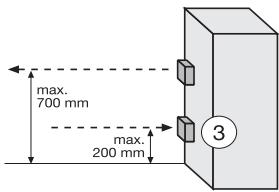
- photocell (active for closing), max. height 200mm
First photocell.
- photocell (active for opening), max. height 200mm
Second photocell.
- Flashing light (optional)
Important visual information on the movement of the gate.
- Key-operated switch
Is mounted on the outside. The gate is opened by key or by entering a number.
- Contact strip (optional)
Safeguards the gate on being touched. Contact strips can be mounted on the gate or on the pillars. If required, contact strips must be mounted at a height of up to 2.5m .
- photocell (active for opening/closing), max. height 200 mm (optional)

The control board complies with the latest EU
guidelines. One of these guidelines specifies that the closing forces at the gate edge must not exceed 400N (40 kg) for the last 500 mm before the door is CLOSED. Above 500 mm, the maximum force at the gate edge must not exceed 1400 N (140 kg). If this cannot be ensured, a contact strip must be mounted on the gate at a height up to 2.5 m or on the pillar on the opposite side (EN12453).
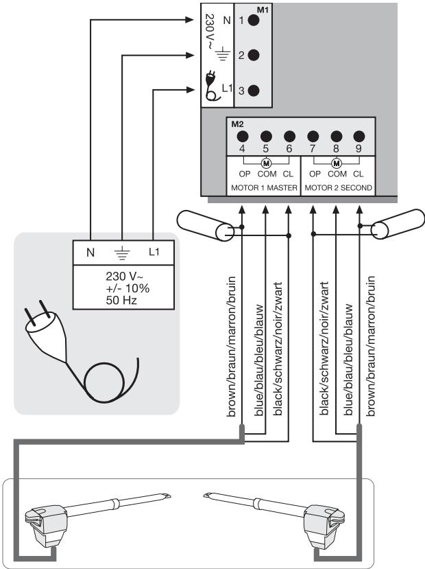
MOTORS:
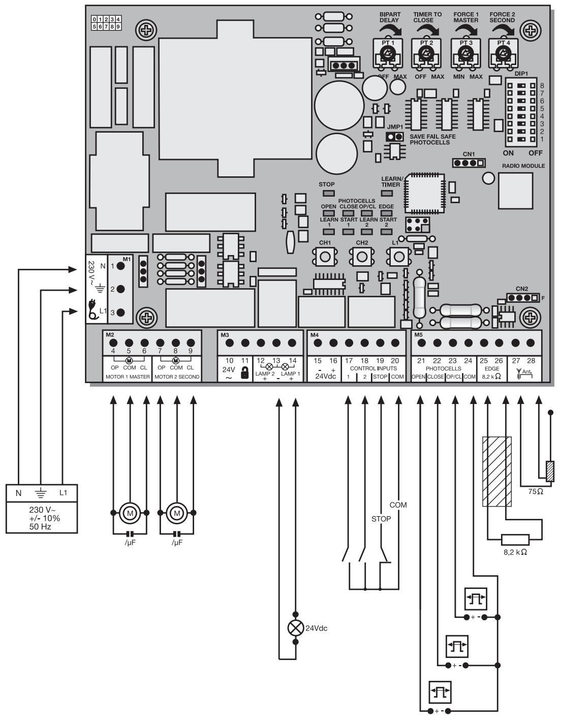
The motor to open first is the "master" motor 1, the other one is the "second" motor 2. If only one motor is used, the connection for motor 2 is held in reserve.
The cable for the capacitors supplied with the motors must be inserted in terminals OP and CL together with the cables for the direction of rotation (brown/black). For space reasons the capacitors may also be installed in the distribution boxes. Make sure that they are connected correctly and powered sufficiently. The capacitors are responsible for the force that the motors will have later on.
First connect the motors as follows:
Motor 1
4 Brown & capacitor 1
5 Blue
6 Black & capacitor 1
Motor 2
7 Black & capacitor 2
8 Blue
9 Brown & capacitor 2
To start up see the section Initial operation / basic setting.
Note: During initial operation, the gate wings must OPEN for the first run. If one or both wings close(s) instead of opening, the brown and black cables must be swapped on this motor. Disconnect from the power supply before doing so!
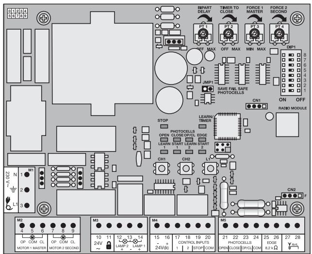
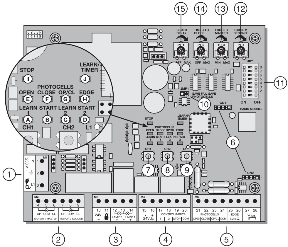
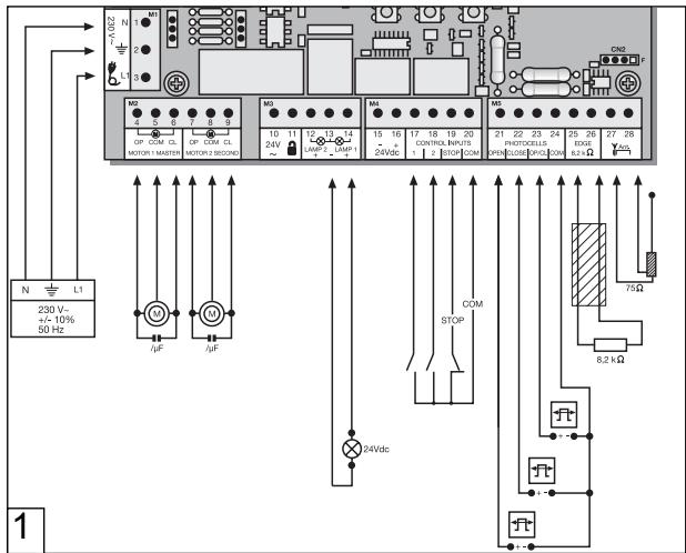
| POINT | DESCRIPTION | FUNCTION |
| 1 | M1, terminals:1,2,3 | Feeder cable |
| 2 | M2, terminals:4,5,6 | Drive 1 (master) |
| Terminals:7,8,9 | Drive 2 (second) |
| 3 | M3, terminals:10,11 | no function |
| Terminals:12,13 | no function |
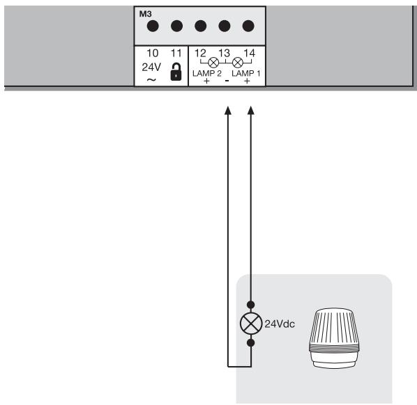
| Terminals:13,14 | Flashing lamp |
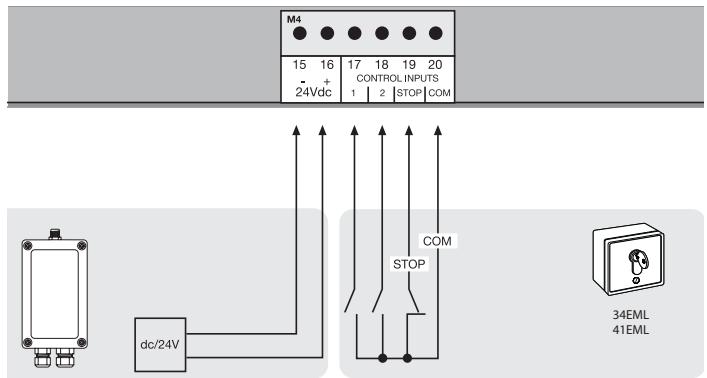
| 4 | M4, terminals:15,16 | Connection for accessories 24V |
| Terminals:17,20 | Impulse transmitter channel 1 |
| Terminals:18,20 | Impulse transmitter channel 2 |
| Terminals:19,20 | Emergency-stop push-button / must be bridged without switch connected |
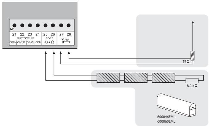
| 5 | M5,terminals:21,24 | photocell active OPEN |
| Terminals:22,24 | photocell active CLOSED |
| Terminals:23,24 | photocell active OPEN + CLOSED |
| Terminals:25,26 | Contact strip 8.2 kilo ohms |
| Terminals:27,28 | Antenna |
| 6 | CN1/CN2, connector | Radio module sockets |
| 7 | CH1, pushbutton | Learn/Delete radio channel 1 |
| 8 | CH2, pushbutton | Learn/Delete radio channel 2 |
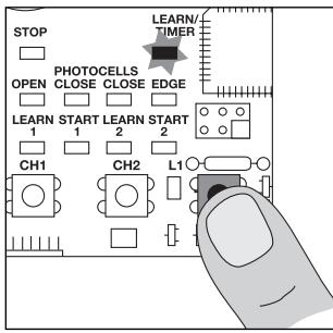
| 9 | L1, pushbutton | Learning the distance covered |
| 10 | JMP1, jumper | Programming the photocell |
| 11 | DIP1 | Dip switch block |
| 12 | PT4, potentiometer | Force setting drive 2 |
| 13 | PT3, potentiometer | Force setting drive 1 |
| 14 | PT2, potentiometer | Automatic closing |
| 15 | PT1, potentiometer | Bipart delay |
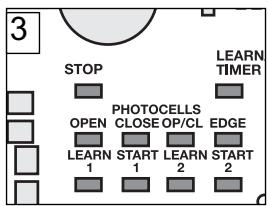
DESCRIPTION OF THE LEDs
RED LEDs should be switched off. Indication of faults to be rectified; this does not apply to failsafe photocells not connected. (see "JUMPER" description)
(Example: short circuit, photocells and/or contact strip)
POINT DESCRIPTION
LED A RED Learn/Delete radio channel 1
LED B RED Start impulse channel 1
LED C RED Learn/Delete radio channel 2
LED D RED Start impulse channel 2
LED E RED photocell active for OPEN
LED F RED photocell active for CLOSE
LED G RED photocell active for OPEN/CLOSE
LED H RED contact strip
LED I GREEN stop
LED J RED learn program (distance covered)
| PROGRAMS
The control board has 3 operating modes (programs). The desired program is set using the dip switch “ON” or “OFF”. |
| DIP1 | ON | The various operating modes are assigned to the drives (see separate table) |
| DIP2 | OFF |
| DIP3 | ON |
| OFF | |
| DIP4 | | no function |
| | |
| DIP5 | ON | Setting for Chamberlain photocells (771EML), complies with EN60335-2-103. |
| OFF | Setting for relay-controlled photocells (263EML) or other relay photocells. |
| DIP6 | ON | Preflash function of flashing light 2 seconds before the drive starts. |
| OFF | Preflash function disabled |
| DIP7 | ON | Once the gate has fully opened, drive 1 moves the gate with maximum force for 1 second in “OPEN” direction. |
| OFF | Function disabled |
| DIP8 | | no function |
| | |
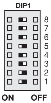
Only modify settings when control bord is disconnected. Otherwise modifications will not be accepted!!!
POTENTIOMETER
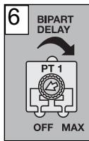
PT1 (TRIMMING POTENTIOMETER 1): BIPART DELAY
Controls the bipart delay if wings overlap. For OPEN = 0 or 3 sec. For CLOSED = 0-20 sec. Motor 1 (master) is opened first and closed last. It is necessary that the bipart delay is always set so that nobody is caught between the wings when they close. Left stop: Bipart delay OFF
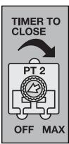
PT2 (TRIMMING POTentiometer 2): AUTOMATIC CLOSING (TIMER TO CLOSE)
The waiting time for the gate for GATE OPEN can be defined. The gate is closed 0-150 sec. after the set time expires.
Only working with failsafe photocell(s) 771EML installed. Left stop: Automatic closing OFF

The control board complies with the latest EU guidelines.
One of these guidelines specifies that the closing forces at the gate edge must not exceed 400N (40 kg) for the last 500 mm before the door is CLOSED. Above 500 mm, the maximum force at the gate edge must not exceed 1400 N (140 kg). If this cannot be ensured, a contact strip must be mounted on the gate at a height up to 2.5 m or on the opposite pillar (EN12453).
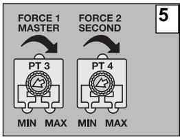
PT3 (TRIMMING POTENTIOMETER 3): FORCE SETTING (FORCE 1 MASTER)
Definition of the force with which motor 1 = master is to operate. The required force depends on weight and function of the gate.
PT4 (TRIMMING POTENTIOMETER 4): FORCE SETTING (FORCE 2 SECOND)
Definition of the force with which motor 2 = second is to operate. The required force depends on weight and function of the gate.
PT1
PT2
PT3
PT4


OFF MAX
OFF MAX
MIN MAX
MIN MAX
Only modify settings when control bord is disconnected. Otherwise modifications will not be accepted!!!
Separate table for setting the operating modes
| DIP1 | DIP2 | DIP3 | Impulse transmitter/channel 1 | Impulse transmitter/channel 2 |
| Standard | ON | ON | OFF | Gate closed:1. impulse opens, the next one stops, the next one closes, the next one stops, the next one opens etc.Impulse during closing stops the gateImpulse during opening stops the gateImpulse during the rest closes the gate immediately | Gate closed:1. impulse opens gate 1 (pedestrian), the next one stops, the next one closes, the next one stops, the next one opens etc.Impulse during closing stops the gateImpulse during opening stops the gateImpulse during the rest closes the gate immediately |
| Standard & no self-hold (hold to run) for closing | ON | OFF | ON | Gate closed:1. impulse opens, the next one stops, the next one closes, the next one stops, the next one opens etc.Impulse during closing stops the gateImpulse during opening stops the gateImpulse during the rest closes the gate immediately | Gate open:Permanent signal required for closing, letting go stopsRadio disabled, safety equipment disabled |
| No self-hold (hold to run) | OFF | OFF | OFF | Gate closed:Permanent signal required, letting go stopsRadio disabled, safety equipment disabled | Gate open:Permanent signal required, letting go stopsRadio disabled, safety equipment disabled |
ACCESSIONS
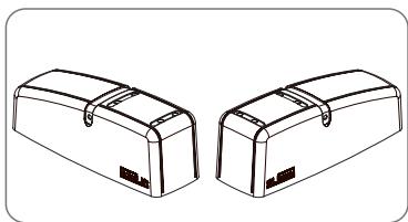
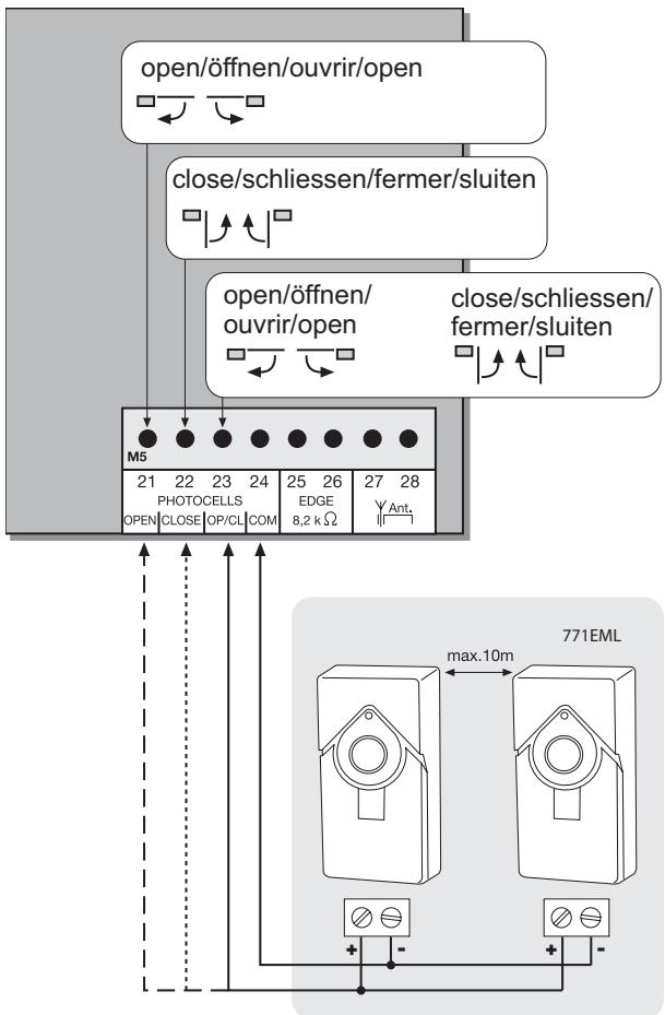
PHOTOCELLS (OPTIONAL)
The photocells are for safeguarding the gate and must be used. The fitting location depends on the gate's design. EN12453 specifies that a pair of photocells must be installed at a height of 200mm and activated to "Close"; a second pair must be installed at a height of 200mm and activated to "Open". A third pair of photocells can be optionally installed and activated to "Close" and "Open". The photocells consist of a transmitter and a receiver and must be opposite each other. The housing of the photocell (plastic) can be opened using a screwdriver. The photocell is mounted on the wall using small screws and wall plugs. It is possible to use two different photocell systems (see Dip switch description). To enable the "Automatic Closing" function, the Chamberlain failsafe photocell must be installed. A combination of photocells is not possible. The Chamberlain failsafe system (2-cable system) has small LEDs (light) that can be seen from the outside on both sides to indicate the status of the photocell. Two Chamberlain failsafe photocell models are available. The one model is ideal for walls lying opposite. The other model is ideal for the inside of the gate, because fittings are already available.
Diagnosis at the Chamberlain fails safe photocell
LED constant = OK
LED flashes = photocell disables control board
LED off = no current, incorrect connection or polarity
Diagnosis on the control board
LED off = OK
LED on constantly = control board disables
LED flashes = OK no photocell connected
Cable cross-section: 0.5mm^2 or more.
Voltage: 12/24 volts AC/DC.
Do not use any fixed copper lines. Do not lay any 230 volt cables in parallel and do not lay any 2 cables in the same cable trunking.
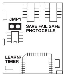
JUMPERS
Programming of failsafe photocells model 771EML
1.Before the Initial Setup
2.When connecting or removing photocell(s)
- Switch off control board (disconnect from current)
- Slip jumper on designated pins
- Dipswitch 5 to "ON"
- Connect photocell(s) according illustration
- Reconnect control board, wait short-time
- Pull jumper, wait short-time
Done! (The number of photocells connected are stored)
Programming of relay photocells such as 263EML
The control board must be disconnected from the mains for a few seconds. All terminals to which no photocell is connected must be bridged with COM. (21-24, 22-24, 23-24). The power supply for the relay photocell of terminals 15-16. Dip switch 5 must be at OFF. The jumper must be unplugged.
Note: Relay photocells are no longer permitted for new installations as per EN12978, because they cannot perform self-checks (failsafe).
Operation without photocells
DANGER: Not permitted for normal operation. In this case contact strips must safeguard the gate.
The control board must be disconnected from the mains for a few seconds. Terminals 21-22-23-24 must all be bridged. Dip switch 5 must be at OFF. The jumper must be unplugged.
Note: It is not possible to combine different photocell models.
FLASHING LAMP (OPTIONAL)
A flashing lamp can be connected to the control board. It warns when the gate is being moved. The flashing light should be fitted as high as possible and in good clear view. The control board emits a constant signal that the lamp converts to a flashing signal.
Cable cross-section: 0.5mm^2 or more.
Voltage: 24 V DC

Do not use any fixed copper lines. Do not lay any 230 volt parallel and do not lay any 2 cables in the same cable
The control board / drive can be activated using various inputs. This can be done using a transmitter or keyswitch (terminals 17 and 20).
Transmitter = see "Teaching the transmitter"
Switch input 1 = input control 1 normal operation
Switch input 2 = input control 2 active for special settings
(see Dip switch description)
EMERGENCY STOP (OPTIONAL)
A switch can be connected to stop or disable the unit. The movement of the wings is stopped immediately. Terminals 19 and 20 must be bridged if no switch is installed.
24 VDC - OUTPUT
For relay infrared senors or other devices (e.g. receivers) max. 500mA

- Do not use any fixed copper lines. Do not lay any 230 voltage cables in parallel and do not lay any 2 cables in the same cable string.
A contact strip working according to the 8.2 kilo ohm principle can be connected to the control board, i.e. a 8.2 kilo ohm test resistor is attached to the end of the contact strip. It ensures that the electric circuit is monitored permanently. The control board is supplied with an 8.2 kilo ohm resistor installed. Several contact strips are connected in series.
Cable cross-section: 0.5mm^2 or more.
ANTENNA (OPTIONAL) ANT4X-1EML
The control board is standard-equipped with a wire antenna. An external antenna (accessory) can be connected to terminals 27 and 28. A larger range (radio) can thus be achieved. Mount the antenna as high as possible.

Do not use any fixed copper lines. Do not lay any 230 volt cables in parallel and do not lay any 2 cables in the same cable trunking.
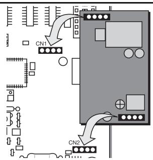
RADIO MODULE (plugged)
To operate the control board via radio remote control, a radio module must first be installed in slots CN1/CN2.
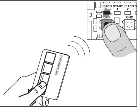
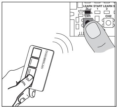
TEACHING / DELETING THE TRANSMITTERS
Press button CH1. The LED "Learn1" lights up red. Now press one of the transmitter's button for approx. 5 seconds. The LED "Learn 1" flashes now. Finished. Proceed in exactly the same way for CH2. However, now press one of the transmitter's buttons that has not yet been assigned. Up to 128 transmitters can be programmed in this way.
To delete the programmed transmitter setting, simply press button CH1 until the LED goes out. Proceed in the same way for CH2.
INITIAL OPERATION
BASIC SETTING
Proceed step by step. If you are not sure, start again at the beginning. Take sufficient time to make these settings.
- Are all components required for operation connected? Motors, photocells, safety contact strip, stop switch.
- Make sure that nobody is present in the range of the gates.
-
Check if the LEDs (lamps) are OK or whether they are blocking any functions. Red LEDs (lamps) should not be on permanently. The green LED must be on.
-
Set the dip switch program standard 1="ON", 2="ON", 3="OFF". Later corrections can be made at all times.
- Set force potentiometer "FORCE 1" "FORCE 2" to max. 30% . Even lower if the gates are very light. Try before correcting! Only increase the force in small steps.
- If two motors are connected, the bipart delay must be set. Turn the potentiometer to approx. 50% . Later corrections can be made at any time.
- Switch off control board (disconnect from current)
7.1 Slip jumper on designated pins
7.2 Dipswitch 5 to "ON"
7.3 Connect photocell(s) according illustration
7.4 Reconnect control board, wait short-time
7.5 Pull jumper, wait short-time
Done! The LED(s) of the photocell(s) connected stay(s) out.
The LED(s) of the photocell(s) not connected will flash.
Programming the time for the standard distance covered (without soft-stop, slow run)
Note: If only one drive (1-wing operation) is used, the learning steps for wing 2 are different.
For "standard" programming: See the text for information.
For "advanced" programming skip step 5,6,7 and 8 by pressing button L1.
Button L1 must be pressed twice for this program.
- The wings should be closed and locked.
- Press button L1 briefly (1 second), both wings open.
Note: If one or both wings close instead of opening, the brown and black cables must be swapped on this motor. Switch off the power (restart), then start programming again from the beginning.
- Press L1 again when both wings have reached the limit stop (+ let it buzz for two seconds). Only wing 2 is now running, it closes now. When wing 2 has closed, wing 1 starts to run automatically and closes.
Note: If only one wing is used, please wait (for about 15 seconds) without pressing any button, wing 1 starts to move automatically.
Continue with the completion of the installation
Completion of the installation/programming: Once the covered distance is programmed, the transmitters can be programmed (not required for kits) or deleted.
- Start the gate with the transmitter or a connected button and observe the process. Close the gate again WITHOUT having made any settings.
- If the gate does not close completely by itself, adjust the potentiometer to other values, adapted to fit the experience value from the test. (e.g. increase running time, correct force, bipart delay) Caution: The wing must run for at least one second at the stop so that it reaches the stop in the even of wind loads (slower). It is not possible to compensate this using increased force. The programming of the running time must be repeated.
- Now start a second attempt and proceed again as above. Close the gate first before you make any settings.
- Once all settings have been made, check the function of the photocells, buttons, flashing lamp, transmitters, accessories etc. If you desire automatic closing, set the potentiometer for the rest to gate OPEN ("timer to close").
- Show all persons that use the gate how the gate moves, how the safety functions work and how to operate the drive by hand.
Programming the "Advanced" distance covered (individual)
Button L1 must be pressed 9x in all for this program. Each time this is done a position (time) is saved. This makes it possible to save the soft stop (slow run) for the individual adaptation of the gate or application. Very long soft stop phases or almost none are possible.
Wing 1 = "master"
Wing 2 = "second"
1. The wings should be closed and locked.
2. Press L1; for more than 5 seconds = until wing 1 starts (opens). Let go of button!!
3. Press L1 again; soft stop OPEN for wing 1 begins at this position.
4. Press L1 again; limit stop reached (+2 seconds) Wing 2 now starts automatically.
5. Press L1 again; soft stop OPEN for wing 2 begins at this position.
6. Press L1 again; limit stop reached (+2 seconds) Wing 2 now restarts automatically and closes.
7. Press L1 again; soft stop CLOSED for wing 2 begins at this position.
8. Press L1 again; limit stop CLOSED reached (+2 seconds) Wing 1 now starts automatically.
9. Press L1 again; soft stop CLOSED for wing 1 begins at this position.
10. Press L1 again; limit stop CLOSED reached (+2 seconds)
Finished
Frequently asked questions
| How long is the probable service life of a gate opener? | When used for private purposes, a correctly installed gate opener can operate perfectly for in excess of 10 years. Both the gate and the gate opener must be checked regularly and serviced in accordance with their respective instructions. |
| How long does it take to install a gate opener? | Depending on your specific technical skills, the installation of the mechanical components can take approx. 3 to 4 hours. Firstly, the gate needs to be properly prepared such that installation work can commence. The electrical connection work takes approx. 1 to 2 hours. Each user should be instructed for at least 30 minutes with regard to the operation of the gate opener, whereby its functionality should be demonstrated and safety aspects, protective facilities and procedure in case of power failure should all be explained. |
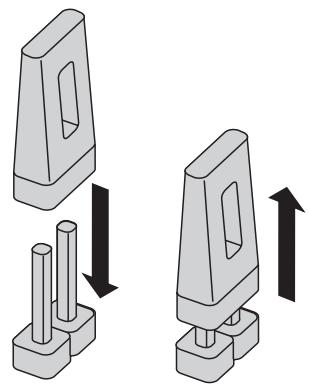
| What happens in case of power failure? | All Chamberlain gate openers are equipped with a release system by means of which the gate can be operated manually in case of power failure. |
| Is it possible to open just one wing of the gate (pedestrian mode)? | Yes, it is possible. This process can be operated via remote control (a 2-channel remote control is the minimum requirement here) or via switch operation (see “Standard” operation mode setting).709441 |
| Gate opener does not function / does not respond when button is pressed. | 1. Connection to button is loose.
2. STOP switch connection is loose; STOP LED is off.
3. Obstacle is blocking photocell in direction of movement.
4. Safety edge is damaged or has encountered an obstacle.
5. Gate opener is still released. | 1. Check button and COM connections.
2. Check STOP switch connections (STOP and COM).
3. Remove obstacle.
4. Remove obstacle and check connections and wiring.
5. Lock gate opener. |
| Immediately after the gate has started moving, it stops and reverses. | Obstacle in area of gate. | Check area of gate for objects |
| The gate opener does not open the gate fully. | 1. Are the post dimensions A+B correct?
2. Has the running time of the controller been set correctly?
3. Has the force been set correctly? | 1. Check A+B dimensions.
2. Reprogram as required – plus approx. 3 seconds.
3. Correct force setting (gate opener runs somewhat slower in windy conditions). |
| The gate opener hums slightly but has no force | 1. Capacitor is not correctly connected to the brown and black cable.
2. Force has not been set.
3. The gate opener has been released. | 1. Check wiring of capacitor.
2. Turn force potentiometer in a clockwise direction.
3. Lock gate opener. |
| The controller doesn't respond when I alter the Dip-switches. | | Disconnect controller from power supply, then alter Dip-switches. |
| The gate opener only works when I press and hold the button on the remote control. | 1. Controller in 'hold to run' operating mode.
2. A safety facility is not working correctly (photocell, safety edge). | 1. Disconnect controller from power supply, then alter Dip-switches.
2. Observe LEDs; find and rectify fault.
1. Only works if the 2-cable photocell 770E(ML) or 771E(ML) has been installed.
2. Then turn "timer to close" potentiometer in a clockwise direction. |
| "Timer to close" doesn't work. | | |
| The gate opener doesn't respond at all, although the controller has been connected (LEDs are on). | 1. Remote control has not been programmed.
2. LEDs indicate a fault.
3. Photocell connected incorrectly.
4. Jumper between STOP and COM missing.
5. Motor terminal possibly not connected properly. | 1. Programming remote control.
2. Find and rectify fault(s) (see description of LEDs).
3. Check photocell connection / programming.
4. Connect simple jumper.
5. Check terminals and connections. |
| The gate opener doesn't respond at all; no LED is on. | Possibly power failure. | 1. Check conductor and zero conductor.
2. Check house fusing. |
| The gate opener stops suddenly and then restarts only after a lengthy pause. | If the gate is operated constantly, the motor will reach its cut-off temperature - protective facility - as the gate opener is not designed for permanent operation. | Allow motor sufficient time to cool (min. 15 minutes). |
| The gate opener is so strong that it bends the gate and/or post. | 1. A+B dimensions correct?
2. Force set too high?
3. Reinforce gate? | 1. Check A+B dimensions.
2. Turn force potentiometer in an anticlockwise direction.
3. Possibly screw gate opener to a reinforcement plate (post).
Possibly fit reinforcement plate at point of pull / push pressure (gate wing).
Use suitable screws and plugs |
| Can different A+B dimensions be used on the two sides? | Generally speaking, yes, but the wings then open at different speeds. If the A+B dimensions are altered significantly from the standard setting, the gate will run poorly and the fittings will be subjected to greater stress (considerably reduced service life of installation). |
| The gate must follow a slope. | Not recommended! Change gate! The gate can move in an uncontrolled (dangerous) manner if the gate opener has been released. A stronger force is needed in the upwards direction of the slope and then, in the opposite direction, the gate opener's force is too strong. |
| The force setting has been altered, but no difference is apparent. | Disconnect the controller from the power supply for a few seconds in order to activate the control board's self-diagnosis functionality. |
| The remote control's range is too short. | The installation of an external aerial is recommended as the controller with the short cable aerial is located either behind the post or near ground level in most cases. The optimum location of the aerial is as high as possible in all cases. An appropriate aerial with installation kit can be obtained from Chamberlain as an accessory with the product ref. no. ANT4X-1EML. |
| The gate post is so thick that I am unable to comply with the requisite A+B dimensions. | Reduce post thickness or shift gate location. |
| The control board does not work any more using the transmitter, only with the switch and even then only as long as a button is pressed and kept pressed.
Open with push-button (1) or CLOSE with push-button (2) | 1.Dip switch setting not as desired
2.A safety photocell, a contact strip or the stop disables the control board
3.Only one photocell was connected for OPEN | 1.Correction of the dip switch, elimination of fault required. If the fault cannot be repaired, it will be necessary to “reset” and reprogram (see photocell)
2.At least one photocell must be connected and activated for CLOSED or OPEN & CLOSED. |
| The unit does not close automatically, it OPENS automatically | The motor cables are not connected correctly | The motor cables (brown,black) must be swapped |
| Control board does not work with transmitter | 1.transmitter not programmed
2.An photocell blocks | 1.Program transmitter
2.Checked photocells |
| Gate can only be opened | 1.photocell blocks
2.Dip switch setting not as desired | 1.Function and connection must be checked
2.Checked dip switch |
| The control board is not running | No covered distance learned | Learn covered distance.
See Initial operation |
| The wings do not open completely. | 1.Insufficient force in the event of high wind loads
(entire gates)
2.Gate sluggish/heavy | 1 Reset force (increase )
2.Improve ease of movement
3.Program control board again |
| (Remote controlled) universal receiver does not work | Observe polarity (terminals 15/16) | Swap “+” and “-” cables |
Automatic Gate Opener Models HC280ML, HC300ML/MLS, HC400ML/MLS,
HC600ML/MLS Series
are in conformity to the applicable
sections of StandardsEN300220-3 · EN55014 · EN61000-3 · EN60555, EN60335-1 · ETS
300683·EN60335-1:2002·EN60335-2-103:2003·EN55014-1:2000+A1+A2·
EN55014-2: 2001 • EN61000-3-2: 2000 • EN61000-3-3: 1995 + A1 • EN 301 489-3,
V1.3.1·EN 300 220-3 V1.1.1·EN 13241-1
per the provisions & all amendments
of the EU Directives 73/23/EEC,89/336EEC,1999/5/EG
Declaration of Incorporation
Automatic Gate Opener Models when installed and maintained according to all the
Manufacturer's instructions in combination with a Gate, which has also been installed and maintained according to all the Manufacturer's instructions, meets the provisions of EU Directive 60/1995/52.
Directive 89/392/EEC and all amendments.
I, the undersigned, hereby declare that the equipment specified above and any accessory listed in the manual conforms to the above Directives and Standards.
B.P.Kelkhoff
Manager, Regulatory Affairs
Chamberlain GmbH
D-66793 Saarwellingen
Januar, 2006

Barbarea P. Keckhoh
BELANGRIJKE INSTRUCTIES VOOR MONTAGE EN GEBRUIK
BEGIN MET HET LEZEN VAN DEZE BELANGRIJKE VEILIGHEIDSINSTRUCTIES!


NOODSTOP (OPTIONEEL)