CB224 - Access Control System CHAMBERLAIN - Free user manual and instructions
Find the device manual for free CB224 CHAMBERLAIN in PDF.
User questions about CB224 CHAMBERLAIN
0 question about this device. Answer the ones you know or ask your own.
Ask a new question about this device
Download the instructions for your Access Control System in PDF format for free! Find your manual CB224 - CHAMBERLAIN and take your electronic device back in hand. On this page are published all the documents necessary for the use of your device. CB224 by CHAMBERLAIN.
USER MANUAL CB224 CHAMBERLAIN
AT/BA/BE/BG/CH/CY/CZ/DE/DK/ES/
FR/GB/GR/HR/HU/IE/IS/IT/LU/MT/NL
NO/PL/PT/RO/RU/SE/SI/SK/TR/YU
Position 1: Standard
Position 1: standard
Tension: 12/24 Volt CA/CC.
13-14 = Input St. 1 service normal
ARRET D'URGENCE (OPTION) 600084
Tension: 12/24 Volt CA/CC.
SURVEILLANCE DU PORTAIL / ECLAIRAGE (OPTION) COM/NO
24 V CC - SORTIE (bornes 8+9)
ANTENNE (OPTION) ANT4X-1LM
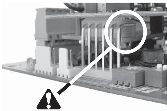
This safety alert symbol means "Caution" - failure to comply with such an instruction involves risk of personal injury or damage to property. Please read these warnings carefully.
This gate drive mechanism is designed and tested to offer appropriately safe service provided it is installed and operated in strict accordance with the following safety rules. Incorrect installation and/or failure to comply with the following instructions may result in serious personal injury or property damage.

When using tools and small parts to install or carry out repair work on a gate exercise caution and do not wear rings, watches or loose clothing.

Installation and wiring must be in compliance with your local building and electrical installation codes. Power cables must only be connected to a properly earthed supply.
Any entrapment possibility by the moving wing between wing & walls must be secured with safety edges or IR-sensors.

Please remove any locks fitted to the gate in order to prevent damage to the gate.

After the installation a final test of the full function of the system and the full function of the safety devices must be done.

This drive cannot be used with a gate incorporating a wicket door unless the drive cannot be operated with the wicket door open.

Make sure that people who install, maintain or operate the gate drive follow these instructions. Keep these instructions in a safe place so that you can refer to them quickly when you need to.

This appliance is not intended for use by persons (including children) with reduced physical sensory or mental capabilities, or lack of experience and knowledge, unless they have been given supervision or instruction concerning use of the appliance by a person responsible for their safety.

It is important to make sure that the gate always runs smoothly. Gates which stick or jam must be repaired immediately. Employ a qualified technician to repair the gate, never attempt to repair it yourself.

Keep additional accessories away from children. Do not allow children to play with pushbuttons or remote controls. A gate can cause serious injuries as it closes.
Disconnect electric power to the system before making repairs or removing covers.
A disconnecting device must be provided in the permanently-wired installation to guarantee all-pole disconnection by means of a switch (at least 3mm contact gap) or by a separate fuse.

The full protection against potential squeeze or entrappment must work direct when the drive arms are installed.

Children should be supervised to ensure that they do not play with the appliance.
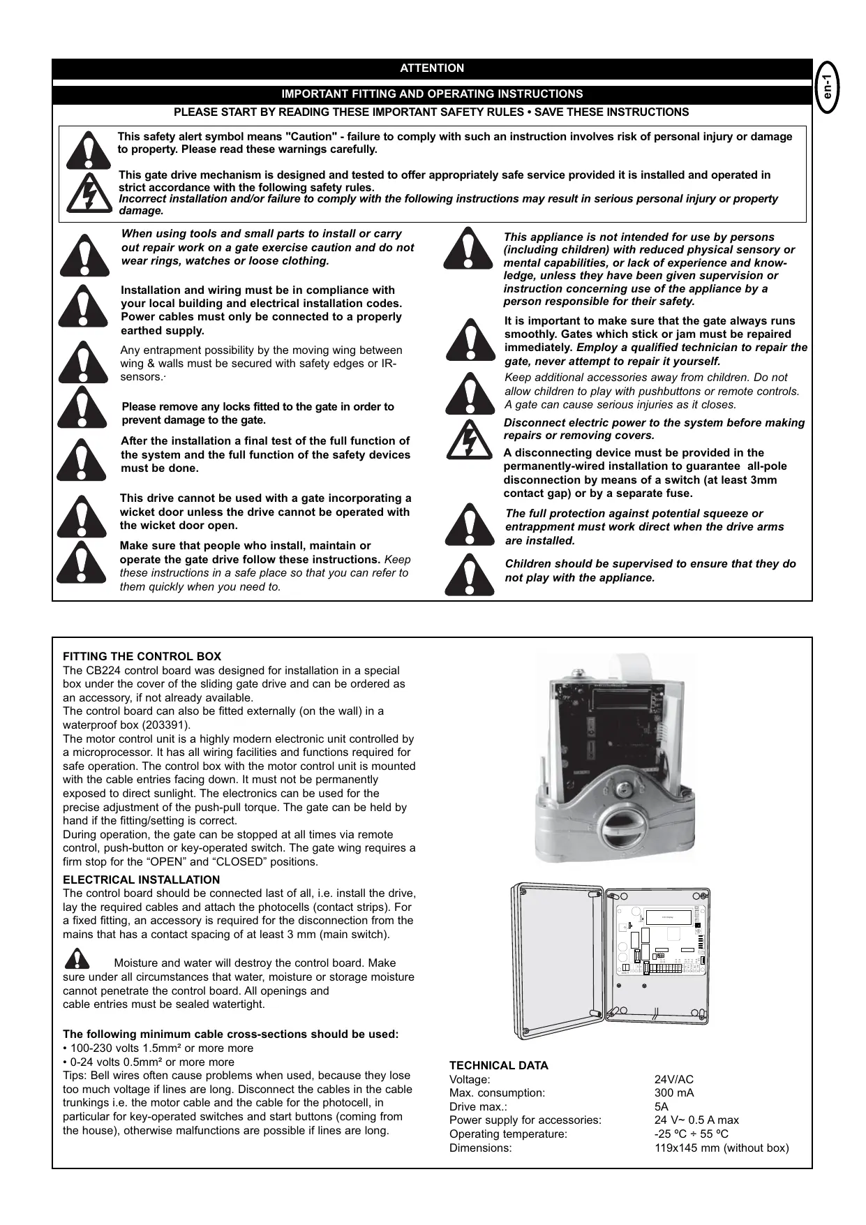
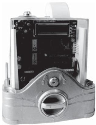
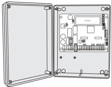
The CB224 control board was designed for installation in a special box under the cover of the sliding gate drive and can be ordered as an accessory, if not already available.
The control board can also be fitted externally (on the wall) in a waterproof box (203391).
The motor control unit is a highly modern electronic unit controlled by a microprocessor. It has all wiring facilities and functions required for safe operation. The control box with the motor control unit is mounted with the cable entries facing down. It must not be permanently exposed to direct sunlight. The electronics can be used for the precise adjustment of the push-pull torque. The gate can be held by hand if the fitting/setting is correct.
During operation, the gate can be stopped at all times via remote control, push-button or key-operated switch. The gate wing requires a firm stop for the "OPEN" and "CLOSED" positions.
ELECTRICAL INSTALLATION
The control board should be connected last of all, i.e. install the drive, lay the required cables and attach the photocells (contact strips). For a fixed fitting, an accessory is required for the disconnection from the mains that has a contact spacing of at least 3 mm (main switch).

Moisture and water will destroy the control board. Make
sure under all circumstances that water, moisture or storage moisture cannot penetrate the control board. All openings and cable entries must be sealed watertight.
The following minimum cable cross-sections should be used:
100-230 volts 1.5mm^2 or more more
- 0-24 volts 0.5 mm^2 or more more
Tips: Bell wires often cause problems when used, because they lose too much voltage if lines are long. Disconnect the cables in the cable trunkings i.e. the motor cable and the cable for the photocell, in particular for key-operated switches and start buttons (coming from the house), otherwise malfunctions are possible if lines are long.
TECHNICAL DATA
Voltage:
Max. consumption:
Drive max.:
Power supply for accessories:
Operating temperature:
Dimensions:
24V/AC
300 mA
5A
24 V~ 0.5 A max
-25°C÷55°C
119x145 mm (without box)
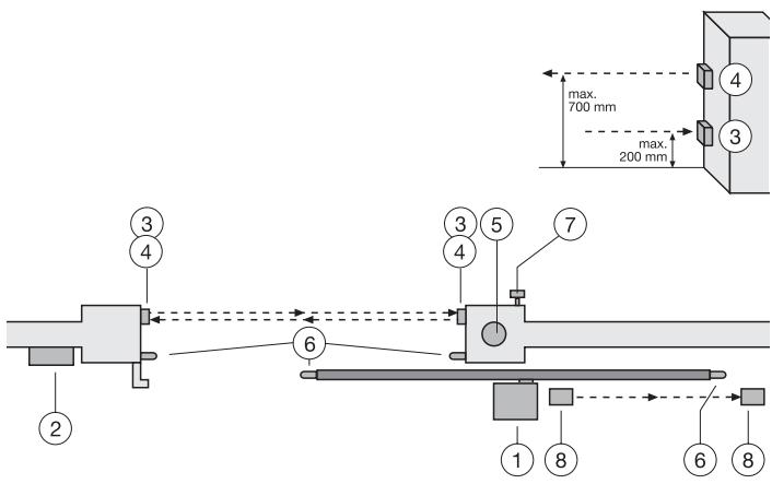
TYPICAL CONFIGURATION OF A UNIT
- Drive with control board
The drive is located on a height-adjustable mounting plate
- Control board (if mounted externally)
If the control board is mounted externally (external mounting box required), the cables and feeder cables must be laid correctly
- photocell (770E/771E) 150-200 mm (optional)
First photocell. Protects people
- photocell (770E/771E) 700 mm (optional)
Second photocell. Protects vehicles and higher objects
- Flashing light
Important visual information on the movement of the gate
- Contact strip (optional) 600213-2
Safeguards the gate on being touched. Contact strips can be mounted on the gate or on the pillars. If the gate has openings exceeding
45mm, a contact strip is required on the pillar (accessory). If required, contact strips must be mounted at a height of up to 2.5m.
- Key-operated switch (optional)
Is mounted on the outside. The gate is opened by key or by entering a number.
- photocell (optional)
Safeguards the gate on opening. This photocell can be omitted if the construction itself prevents people from being present in this area. A contact strip can be fitted here as an alternative option.

The control board complies with the latest EU directives. On
of these directives specifies that the closing forces at the gate edge must not exceed 400N (40 kg) for the last 500 mm before the gate is CLOSED. Above 500 mm, the maximum force at the gate edge must not exceed 140 N (140 kg). If this cannot be ensured, a contact strip must be mounted on the gate at a height of up to 2.5 m or on the opposite pillar (EN12453).
MOTOR
Connect the motor to the control board exactly as shown on the connection layout diagram.
Terminal 3 red wire L/N
Terminal 4 blue wire N/L
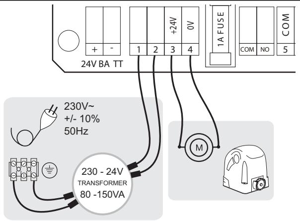
Note: If drives/motors other than ours are connected, it might be required to swap the cables of terminals 3 + 4 to ensure correct operation. This is shown during "Initial operation", if the control board does not maintain the correct moving directions. See also the Limit switch connection instructions for more information.
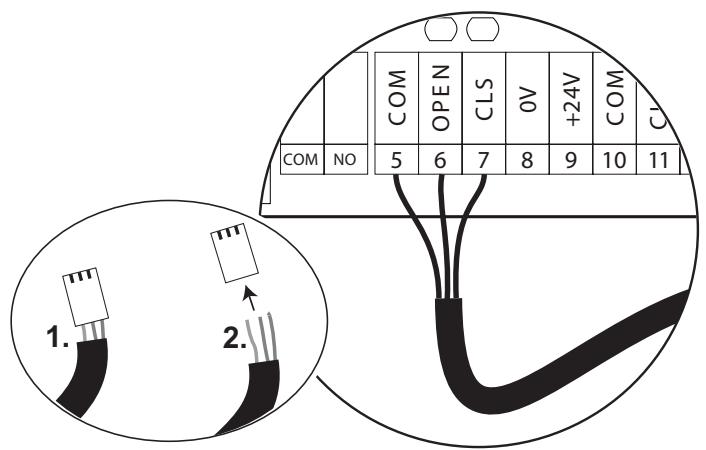
CONNECTION OF WIRES FOR LIMIT SWITCH
Description for Chamberlain drives with magnetic limit switches:
The correct installation of the limit switches UP / DOWN is important for the operation of the unit.
If the entry is LEFT of the drive, then:
Terminal 5 blue
Terminal 6 brown
Terminal 7 black
If the entry is RIGHT of the drive, then exchange terminals 6 + 7 (brown/ black)
FUSES:
F1 = 10A secures the motor
F2 = 1A secures accessories terminals 8 + 9
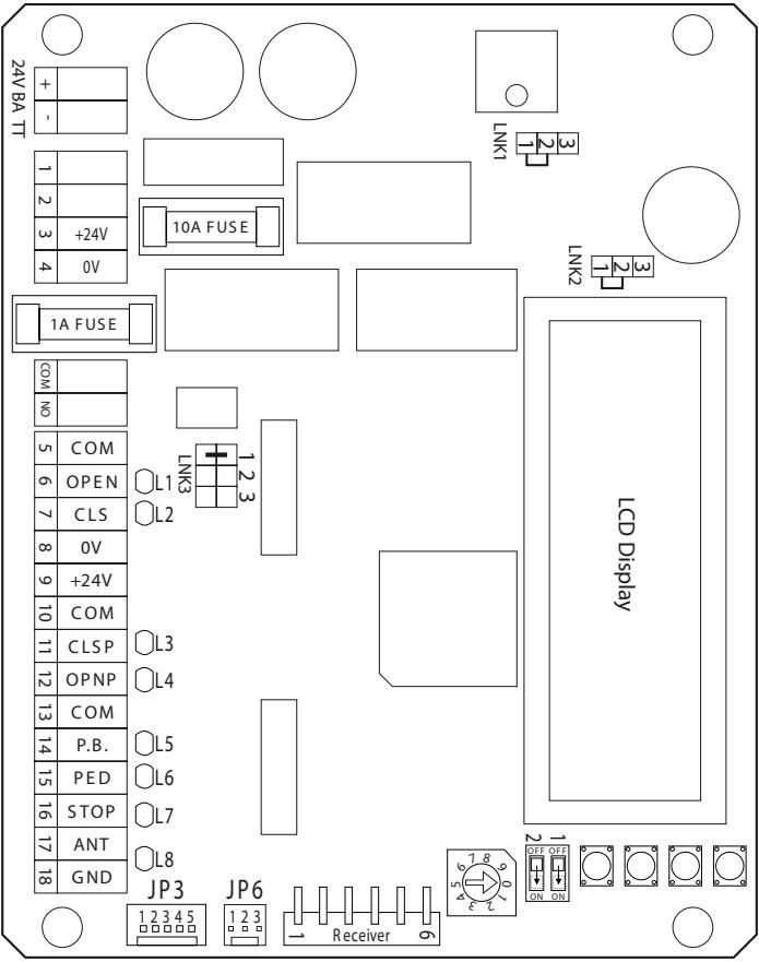
CONNECTIONS:
- 24VAC input
- 24VAC input
- motor output
- motor output
- limit switch COM blue
- limit switch UP brown/blue
- limit switch DOWN blue/brown
- accessories supply 0 Volt
- accessories supply 24 Volt
- photo cells COM
- photo cells DOWN (close)
- photo cells UP (open)
- switch: COM
- switch:UP/DOWN
- switch: pedestrians
- switch: stop (emergency stop)
- antenna signal (not necessary if receiver 80 17 19 6 is used)
- antenna ground
BACKUP BATTERY (OPTIONAL):
A backup battery may be connected. It will supply the unit for a while with power in case of power cut. Depends on battery size and daily amount of cycles. Model CM475 requires a waterproof housing when installed outside.
TURN-SWITCH FOR PROGRAMS 0-9
Position 1: Standard
Gate opens after signal and closes with the next one. During opening sequence the gate first stops and closes and does not close until the next signal. If photo cell transmittance is interrupted during closing sequence, the gate reverses to the fully UP position.
Position 2: Automatic (photo cells necessary)
Gate opens after signal and closes depending on pre-programmed time (in menu P3). If photo cell transmittance is interrupted during closing sequence, the gate fully reverses and closes again after pre-programmed time.
Position 3: Photo cells close gate
Gate opens after signal and closes as soon as photo cell transmittance is interrupted. Interrupting photo cell transmittance during closing sequence results in the gate reversing completely and then closing again after pre-programmed time (in menu P3).
Position 4: counting mode
Gate opens after signal and counts the number of signals that were given. There have to be at least the same number of interruptions at the closing photo cells (CLOS) before the gate actually closes (this program is not possible if two photo cells have been installed in closing direction).
Position 5-0: no function
Plug-in socket - JP3
Enables further functions either through direct connection or via relay to another control, e.g. alarm system / telephone / status indicator gate / computer / counter, etc.
Pin 5 = control / gate status: ON = when control active
Pin 4 = 0 Volt
Pin 3 = +12 Volt for accessories max. 100mA!
Pin 2 = AUX ON (switched) = when gate closing
Pin 1 = AUX ON (switched) = when gate opening
DESCRIPTION OF LED'S
L1 limit switch UP status: ON = limit switch not activated OFF = limit switch activated (gate positioned at limit switch)
L2 limit switch DOWN status: ON = limit switch not activated OFF = limit switch activated (gate positioned at limit switch)
L3 safety input DOWN (10+11): ON = locks control OFF = OK
L4 safety input UP (10+12): ON = locks control OFF = OK
L5 input for switching device (13+14): ON = signal is active OFF = no signal
L6 input for switching device (13+15): ON = signal is active OFF = no signal
L7 STOP contact: ON = OK; OFF = locks control
L8 Board Status Indicator OFF = control in neutral (steady); gate positioned on limit switch DOWN ON = a signal has been transmitted. LED remains ON until gate reaches limit switch DOWN again or until preprogrammed time for closing sequence has lapsed.
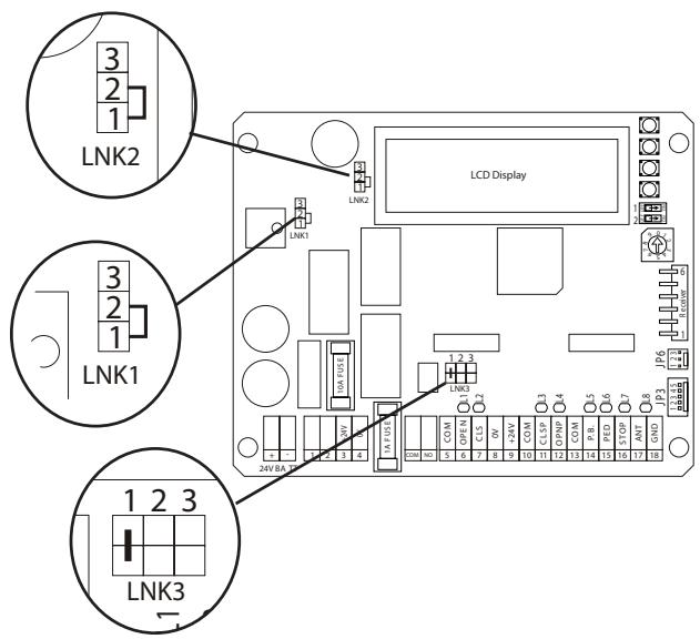
JUMPER LNK
Depending on jumper position several features can be adjusted
LNK1: (do not relocate!)
1 + 2 = (down) for 24V transformer and drive (Chamberlain drives)
2 + 3 = (top) for 12V
LNK2: (do not relocate)
1 + 2 = (down) 24V
2+3(top)12V
LNK3: Flashing lamp (COM-NO)
1= ON during opening and closing, i.e. only with gate movement
2= ON from open to close, i.e. if control is active
3=not in use
ACCESSIONS
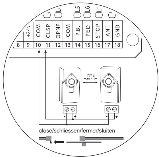
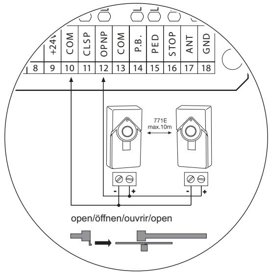
PHOTOCELLS (OPTIONAL)
The photocells are for safeguarding the gate and must be used. The fitting location depends on the gate's design. EN12453 specifies that a pair of photocells must be installed at a height of 200mm . The photocells consist of a transmitter and a receiver and must be opposite each other. The housing of the photocell (plastic) can be opened using a screwdriver. The photocell is mounted on the wall using small screws and wall plugs. It is possible to use two different photocell systems. (see description). To enable the "Automatic closing" function, the Chamberlain failsafe photocell must be installed. The Chamberlain failsafe system (2-cable system) has small LEDs (light) that can be seen from the outside on both sides to indicate the status of the photocell. Two Chamberlain failsafe photocell models are available. The one model is ideal for walls lying opposite.
Settings:
In menu P7 + P8 the control has to be set to the connected photo cells.
For Chamberlain 2-wire photo cells the setting PLS = pulse is required.
For relay-photo cells select setting RLY = relay.
Diagnosis at the Chamberlain failsafe photocell
LED constant = OK
LED flashes = photocell disables control board
LED off = no current, incorrect connection or polarity
Diagnosis on the control board
LED off = OK
LED on constantly = control board disables
Cable cross-section: 0.5mm^2 or more.
Voltage: 12/24 volts AC/DC.
Do not use any fixed copper lines. Do not lay any 230 volt cables in parallel and do not lay any 2 cables in the same cable trunking.
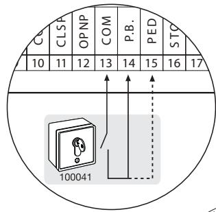
PUSHBUTTON / KEY-OPERATED SWITCH (OPTIONAL)
The control board / drive can be activated using various inputs. This can be done using a hand-held transmitter or key-operated switch (terminals 13-15)).
Hand-held transmitter = see Teaching the hand-held transmitter
13-14 = input control 1. Normal operation
13-15 = input control 2. Active for special settings (see description) Menu P12+P13
EMERGENCY STOP (OPTIONAL) 600084
A switch can be connected to stop or disable the unit. The movement of the wings is stopped immediately. Terminals 13 and 16 must be bridged if no switch is installed.
Cable cross-section: 0,5mm^2 or more.
Voltage: 12/24 volts AC/DC.
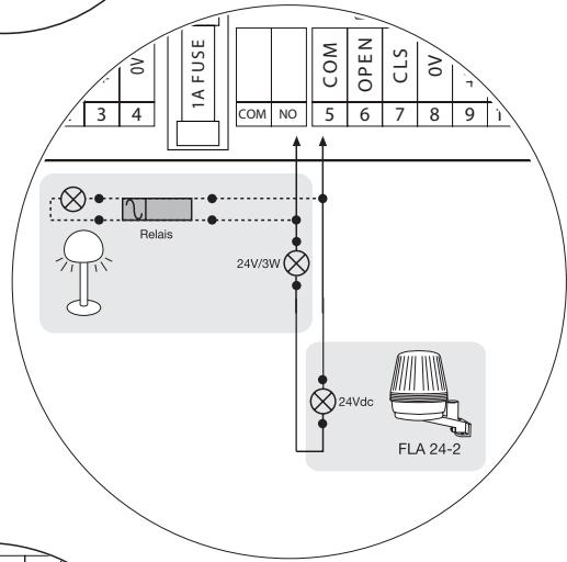
GATE MONITOR / LIGHTING (OPTIONAL) COM/NO
A 24 V/3 W light bulb can be connected to monitor the status of the gate. Alternatively, a yard lighting system can be used by adding a relay.
Setting: see description "Jumper"
Cable cross-section: 0.5mm^2 or more.
FLASHING LAMP (OPTIONAL) FLA24-2 COM/NO
A flashing lamp can be connected to the control board. It warns when the gate is being moved. The flashing light should be fitted as high as possible and in good clear view. The control board emits a constant signal that the lamp converts to a flashing signal.
Setting: see description "Jumper 3"
Cable cross-section: 0.5mm^2 or more.
Voltage: 24 V DC
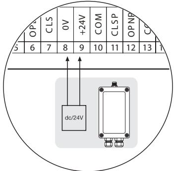
24 VDC - OUTPUT (Terminal 8+9)
For relay infrared senors or other devices (e.g. receivers) max.500 mA

Do not use any fixed copper lines. Do not lay any 230 volt cables in parallel and do not lay any 2 cables in the same cable trunking.
CONTACT STRIP (OPTIONAL) 600213-2
Safety edges with permanent monitoring can be connected via the Interface Box. The Interface Box is connected to the outputs of the photo cell(s).
Cable cross-section: 0.5mm^2 or more
600176 profile size per 1 m
600152 Profile size mounting set
600077-1 Mounting rail 2 m
G-Intset "Profi" transmission set for mounting the strips on the gate wing
G-NSPG45/4 Transmission of signal by means of helix cable (max 8 m in width)
G-AC1103 Strain reliefs/box for helix cable
ANTENNA (OPTIONAL) ANT4X-1LM
If the radio adapter 801719-6 is being used, then terminals 17 + 18 remain vacant. An outdoor antenna is connected directly to the radio adapter.
A larger range (radio) can thus be achieved. Mount the antenna as high as possible.

Do not use any fixed copper lines. Do not lay any 230 volt cables in parallel and do not lay any 2 cables in the same cable trunking.
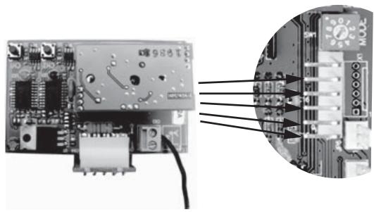
RADIO MODULE 801719-6
To operate the control board via radio remote control, a radio module must first be installed.
TEACHING / DELETING THE HAND-HELD TRANSMITTERS
See description radio adapter.
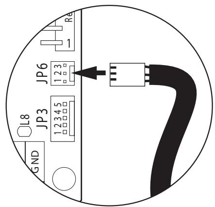
RPM SENSOR
A rotational speed sensor (RPM sensor) can be optionally installed.
The sensor enables the automatic reversing of the gate if an obstacle is detected. RPM sensor: Connector JP6 on the control board
If a battery is being used, the menu P19 must be set to YES.
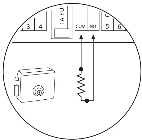
ELECTRIC LOCK (OPTIONAL) Model: 600022 (24V)
The operation of an electrical lock via the contact COM/NO (light output) is possible. If required, please contact our service department.

Do not use any fixed copper lines. Do not lay any 230 volt cables in parallel and do not lay any 2 cables in the same cable trunking.
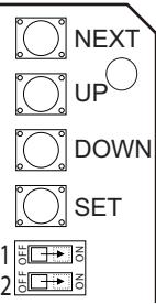
The control is programmed by use of the display. The keys and switches on the right side next to the display are required.
Switch 1:
ON = necessary for programming the control
OFF = locks
Switch 2:
ON = display illumination on
OFF = out
Key SET:
saves current setting
Key UP & DOWN:
changes setting
Key NEXT:
to change to different menu / program
P... =
display of currently accessed menu / program
Def. =
"DEFAULT" factory setting. Ex factory setting
Now =
"NOW" current setting
Yes
"YES
No
“NO”
DISPLAY INDICATION:
| Display | Description | Range | My settings | ||
| P1 | P1=Motor TypeDef:0 Now:0 | motor type | Setting of applied motor: 0 = no motor1 = Chamberlain/LiftMaster; for others: see description | 0 - 3 | |
| P2 | P2=M1 Travel TimeDef:5 Now:5.0s | travel duration | Set travel duration of motor (seconds) | 0 -99 | |
| P3 | P3=Auto Cls Delay Def: 1Now: 1.0s | automatic closing | Duration in seconds of door in open positionATTENTION: only in connection with photo cell(s) | 0 - 99 | |
| P4 | P4=M1 Force AdjDef:50% Now:50% | force setting | Motor force | 30 - 100% | |
| P5 | P5 = Slow DownDef:3 Now: 3.0s | slow travel end | Slow travel in seconds before door - DOWN | 0 - 10 | |
| P6 | P6=M1 Soft StartDef:0 Now: 0.5s | slow travel start | Slow travel in seconds after start | 0 -10 | |
| P7 | P7 = Back Up TimerDef:0 Now: 0.0s | automatic closing special | Only in conjunction with program 3: closes door automatically even after power cut. Time in seconds. Attention: only with connected photo cell(s) | 0 - 65 | |
| P8 | P8 = Open PE TypeDef: RLY Now: RLY | photocell open-direction | Preselection of photo cell type: RLY - relay photo cellPLS - pulse (Chamberlain photo cell 770E and 771E) | RLY - PLS | |
| P9 | P9 = Close PE TypeDef: RLY Now: RLY | photocell close-direction | Preselection of photo cell type: RLY - relay photo cellPLS - pulse (Chamberlain photo cell 770E and 771E) | RLY - PLS | |
| P10 | P10 = PE ReverseDef: Yes Now: Yes | photocell closed-reaction | "YES" = gate reverses to open"NO" = gate stops | No - Yes | |
| P11 | P11 = Opn PE ReOpenDef: No Now: No | photocell open-reaction | During interruptongate stops. After clearance "NO" = reverses (closes); "YES" = opens further | No - Yes | |
| P12 | P12 = PED TravelDef:5 Now: 5.0s | Pedestrian travel duration | Travel duration of motor during pedestrian function (in seconds) | 0 - 99 | |
| P13 | P13 = PED Auto CloseDef: No Now: No | Pedestrian automatic closing | Duration in seconds of gate in open position. P3 must be active. Attention: only in connection with photocells | No - Yes | |
| P14 | P14 = Pwr Fail CloseDef: No Now: No | power cut behaviour | Closes gate automatically even after power failure. Time in seconds. Attention: only with connected photocells | No - Yes | |
| P15 | P15 = Motor SpeedDef: 10 Now: 10 | speed | Speed of gate. Note: by reducing, the max. pulling force cannot be reached | 1 - 10 | |
| P16 | P16 = ExtraOpnTimeDef: 2 Now: 2.0s | travel duration open additional | Additional travel duration of motor to compensate for wind or bad conditions. | 0 - 10 | |
| P17 | P17 = ExtraClsTimeDef: 2 Now: 2.0s | travel duration close-additional | Additional travel duration of motor to compensate for wind or bad conditions. | 0 - 10 | |
| P18 | P18 = Battery TypeDef: 24 Now: 24 | battery type | 2x 12V, no setting possible | 24V | |
| P19 | P19 = BatteryLowOpnDef: No Now: No | battery state of charge | "NO" = gate will not open if battery is empty"YES" = gate will open, but not close | No - Yes | |
| P20 | P20 = RPM SenseDef: No Now: No | RPM sensor | "YES" = RPM sensor is connected (necessary in the EU) "NO" = if nonexistent and if battery is used | No - Yes | |
| P21 | P21 = Total Cyles#Cycles = 0000000 | cycle counter complete | counts all full (completed) cycles | ||
| P22 | P22 = Resettable Cycl#Cycles = 000000 | cycle counter resettable | counts complete cyles since last reset | ||
| P23 | P23 = Reset CyclesDef: No Now: No | cycle counter reset | Reset P22 cycle counter | ||
| P24 | P24 = Reset DefaultDef: No Now: No | factory setting RESET | re-establishes factory settings (not P22) | ||
| P25 | P25 = Software RevRevision ...... | software | indicates installed software version |
Proceed step by step. If you are not sure, start again at the beginning. Take sufficient time to make these settings.
- Are all components required for operation connected? Motor(s), photocell (!), flashing light, push-button or switch etc?
- Make sure that nobody is present in the range of the gates.
- Check whether the LEDs (lamps) are working correctly or whether they are blocking a function.
- OPEN gate by hand and observe LED1 (green). The LED1 (green) must be OFF when limit switch is reached. If necessary exchange wires at terminals 6 + 7 .
- CLOSE gate by hand and observe LED2 (red). The LED2 (red) must be OFF when limit switch is reached.
- If there is no switch connected to control, connect a switch to control contacts 13 + 14 temporarily, in order to complete all settings.
- The control is preset so that operation with ex factory setting is principally possible. Set turn-switch for programs to program 1 "standard". Complete potential changes later (see description).
- Turn switch to 1 (ON) and control/change the following menu settings:
P1 = 1 Chamberlain LiftMaster Motor
P4 = very lightweight gates PVC, aluminium should be operated with less force than is preset (50%).
Set to smaller value in menu.
P4. Max. 30% , otherwise 50%
P5 = slow travel preset to 3 seconds. According to EN12453 the slow travel must be active for the last 50cm of travel distance and should have a duration of at least 5 seconds.
P6 = slow start preset: 0.5 seconds (as required)
P8 = set type of photocell at terminal 12 (UP): RLY for “no” (then small wire jumper is necessary) and relay-photocell or PLS for Chamberlain photocell (2-wire photocell)
P9 = set type of photocell at terminal 12 (DOWN): RLY for “no” (then small wire jumper is necessary) and relay-photocell or PLS for Chamberlain photocell (2-wire photocell)
P20 = RPM sensor: if RPM sensor is connected to terminal JP3 then change to YES in menu
FIRST TRAVEL
- Disengage control from power supply for 5 seconds. If a battery is designated for operation, then disconnect from unit completely until setting is complete.
- Position gate halfway (not to limit switch) and lock in place.
- Activate connected switch and observe gate. The gate must open! If gate closes as instead of opens, immediately stop via switch. The motor with wire (red/blue) terminals 3 + 4 is connected the wrong way around. Exchange wires and start again with point 1.
- If first travel is completed without fault, then it may proceed further to limit switch. Set required travel duration in menu P2. This is the time required for the drive to reach the limit switch safely. If the gate is prone to wind or is stiff, program additional time in menu P16 and P17.
Ex factory setting: 2 seconds.
- Check all settings. Correct force, adjust travel duration, check photo cells
- Check force according to EN12453 and EN12445
NOTE: many of the settings of the control unit have an indirect impact on the travel duration (speed) required for reaching the limit switches. After completion of settings always check if speed is still adequate or maybe even too fast.
COMPLETION OF THE INSTALLATION/PROGRAMMING
Once the covered distance is programmed, the hand-held transmitters can be programmed (not required for kits) or deleted.
- Start the gate with the hand-held transmitter or a connected button and observe the process. Close the gate again WITHOUT having made any settings.
- Once all settings have been made, check the function of photocells, buttons, flashing lamp, hand-held transmitter, accessories etc. If you desire automatic closing, see Display Indication
- Show all persons that use the gate how the gate moves, how the safety functions work and how to operate the drive by hand.
| How long does it take to install a gate opener? | Depending on your specific technical skills, the installation of the mechanical components can take approx. 3 to 8 hours. Firstly, the gate needs to be properly prepared such that installation work can commence. The electrical connection work takes approx. 1 to 2 hours. Each user should be instructed for at least 30 minutes with regard to the operation of the gate opener, whereby its functionality should be demonstrated and safety aspects, protective facilities and procedure in case of power failure should all be explained. | |
| What happens in case of power failure? | All Chamberlain gate openers are equipped with a release system by means of which the gate can be operated manually in case of power failure. | |
| Is it possible to open wing for pedestrian mode? | Yes, it is possible. This process can be operated via remote control (a 2-channel remote control is the minimum requirement here) or via switch operation. | |
| Gate opener does not function / does not respond when button is pressed. | 1. Connection to button is loose. 2. STOP switch connection is loose; STOP LED is off. 3. Obstacle is blocking photocell in direction of movement. 4. Safety edge is damaged or has encountered an obstacle. 5. Gate opener is still released. | 1. Check button and COM connections. 2. Check STOP switch connections (STOP and COM). 3. Remove obstacle. 4. Remove obstacle and check connections and wiring. 5. Lock gate opener. |
| Immediately after the gate has started moving, it stops and reverses. | Obstacle in area of gate. | Check area of gate for objects |
| Gate can only be opened | 1. Photocell blocks 2. Dip switch setting not as desired | 1. Function and connection must be checked 2. Check dip switch |
| "Timer to close" doesn't work. | 1. Only works if the 2-cable photocell 770E(ML) or 771E(ML) has been installed. 2. Then turn "timer to close" potentiometer in a clockwise direction. | |
| The gate opener hums slightly but has no force | 1. Capacitor is not correctly connected to the brown and black cable. 2. Force has not been set. 3. The gate opener has been released. | 1. Check wiring of capacitor. 2. Turn force potentiometer in a clockwise direction. 3. Lock gate opener. |
| The gate opener doesn't respond at all, although the controller has been connected (LEDs are on). | 1. Remote control has not been programmed. 2. LEDs indicate a fault. 3. Photocell connected incorrectly. 4. Jumper between STOP and COM missing. 5. Motor terminal possibly not connected properly. | 1. Programming remote control. 2. Find and rectify fault(s) (see description of LEDs). 3. Check photocell connection / programming. 4. Connect simple jumper. 5. Check terminals and connections. |
| The unit does not close automatically, it OPENS automatically | Check setting of limitswitch | Limitswitch connected falsely |
| Control board does not work with transmitter | 1. Transmitter not programmed 2. A photocell blocks | 1. Program transmitter 2. Check photocells |
| The control board is not running | No covered distance learned | Learn covered distance. See Initial operation |
| Universal receiver does not work | Observe polarity | Swap "+" and "-" cables |
| The wing does not open completely. | 1. Is the gate travel programmed correctly? 2. Is the force adjusted correctly? | 1. Program gate travel again 2. Increase force (under wind load the operator may run a bit slower) |
| The force setting has been altered, but no difference is apparent. | Disconnect the controller from the power supply for a few seconds in order to activate the control board's self-diagnosis functionality. | |
| The remote control's range is too short. | The installation of an external aerial is recommended as the controller with the short cable aerial is located either behind the post or near ground level in most cases. The optimum location of the aerial is as high as possible in all cases. An appropriate aerial with installation kit can be obtained from Chamberlain as an accessory with the product ref. no. ANT4X-1EML. | |
| The gate must follow a slope. | Not recommended! Change gate! The gate can move in an uncontrolled (dangerous) manner if the gate opener has been released. A stronger force is needed in the upwards direction of the slope and then, in the opposite direction, the gate opener's force is too strong. | |
BELANGRIJKE INSTRUCTIES VOOR MONTAGE EN GEBRUIK
BEGIN MET HET LEZEN VAN DEZE BELANGRIJKE VEILIGHEIDSINSTRUCTIES!

BESCHRIJVING VAN DE LED's
L8 Board status indicator:
Def. = "DEFAULT" fabrieksinstalling. Instelling af fabriek
externa, el interruptor de arranque (de fabrica); de lo contrario seSEOSEOSEOSEOSEOSEOSEOSEOSEOSEOSEOSEOSEOSEOSEOSEOSEOSEOSEOSEOSEOSEOSEOSEOSEOSEOSEOSEOSEOSEOSEOSEOSEOSEOSEOSEOSEOSEOSEOSEOSEOSEOSEOSEOSEOSEOSEOSEOSEOSEOSEOSEOSEOSEOSEOSEOSEOSEOSEOSEOSEOSEOSEOSEOSEOSEOSEOSEOSEOSEOSEOSEOSEOSEOSEOSEOSEOSEOSEOSEOSEOSEOSEOSEOSEOSEOSEOSEOSEOSEOSEOSEOSEOSEOSEOSEOSEOSEOSEOSEO SEO
DATOS TECNICOS
Voltaje:
Consumo maximal: