
MagicSpeed CBI 200 - Air conditioner DOMETIC - Free user manual and instructions
Find the device manual for free MagicSpeed CBI 200 DOMETIC in PDF.


| Product Type | Roof Fan for Motorhome and Caravan |
| Brand | Dometic |
| Model | MagicSpeed CBI 200 |
| Dimensions (L x W x H) | 400 x 400 x 110 mm |
| Weight | 4.5 kg |
| Power Supply | 12 V DC |
| Power Consumption | 0.5 to 3 A |
| Fan Speed | Adjustable (multiple speeds) |
| Controls | Control panel with LED display |
| Main Functions | Ventilation, extraction, air circulation |
| Rain Sensor | Yes, automatic closure in rain |
| Remote Control | Included (wireless) |
| Air Filter | Washable and reusable |
| Installation | For flat roof, max thickness 50 mm |
| Maintenance and Cleaning | Clean filter regularly, wipe with damp cloth |
| Safety | Automatic shut-off in case of overheating |
| Spare Parts | Filter, hood, remote control available |
| Repairability | Repairability index not provided |
| General Information | Use in motorhome, caravan, boat |
Frequently Asked Questions - MagicSpeed CBI 200 DOMETIC
User questions about MagicSpeed CBI 200 DOMETIC
0 question about this device. Answer the ones you know or ask your own.
Ask a new question about this device
Download the instructions for your Air conditioner in PDF format for free! Find your manual MagicSpeed CBI 200 - DOMETIC and take your electronic device back in hand. On this page are published all the documents necessary for the use of your device. MagicSpeed CBI 200 by DOMETIC.
USER MANUAL MagicSpeed CBI 200 DOMETIC
SP950T
EN Assembly kit for MAN TGX, TGS (XXL, XLX, XL, LX) Installation Manual 9 DE Montagesatz für MAN TGX, TGS (XXL, XLX, XL, LX) Montageanleitung 25 FR Kit de montage pour MAN TGX, TGS (XXL, XLX, XL, LX) Instructions de montage.... 43 ES Juego de montaje para MAN TGX, TGS (XXL, XLX, XL, LX) Instrucciones de montaje .....61 PT Kit de montagem para MAN TGX, TGS (XXL, XLX, XL, LX) Instruções de montagem ..... 79 IT Set di montaggio per MAN TGX, TGS (XXL, XLX, XL, LX) Indicazioni di montaggio ..... 96 NL Montageset voor MAN TGX, TGS (XXL, XLX, XL, LX) Montagehandleiding....114 DA Monteringssæt til MAN TGX, TGS (XXL, XLX, XL, LX) Monteringsvejledning 132
SV Monteringssats för MAN TGX, TGS (XXL, XLX, XL, LX) Monteringsanvisning....150 NO Monteringssett for MAN TGX, TGS (XXL, XLX, XL, LX) Monteringsanvisning....167 FI Asennussarja malleihin MAN TGX, TGS (XXL, XLX, XL, LX) Asennusohje....183 RU Монтажный комплект для MAN TGX, TGS (XXL, XLX, XL, LX) Инструкция по монтажу ..... 200 PL Zestaw montażowy do MAN TGX, TGS (XXL, XLX, XL, LX) Instrukcja montażu....218 SK Montážna súprava pre MAN TGX, TGS (XXL, XLX, XL, LX) Návod na montáž 236 CS Montážní sada pro vozidla MAN TGX, TGS (XXL, XLX, XL, LX) Návod k montáži.... 253 HU Szerelőkészlet a következőkhöz: MAN TGX, TGS (XXL, XLX, XL, LX) Szerelési útmutató .....270
4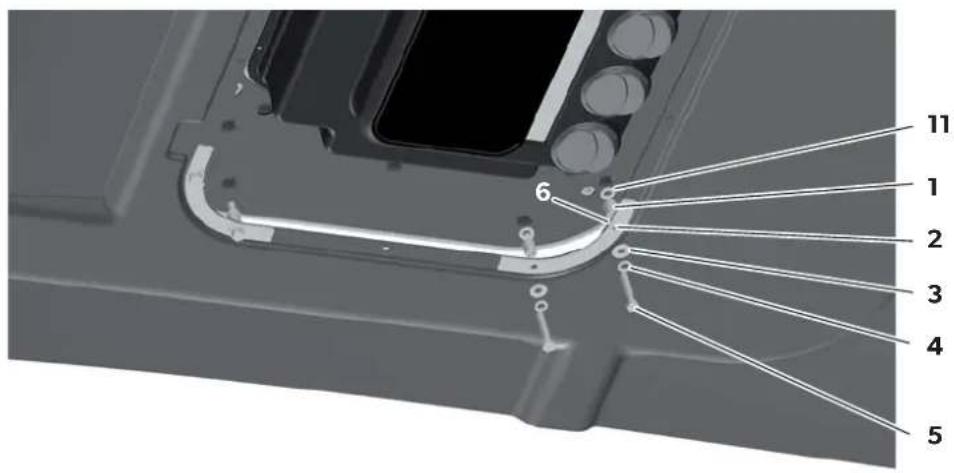
5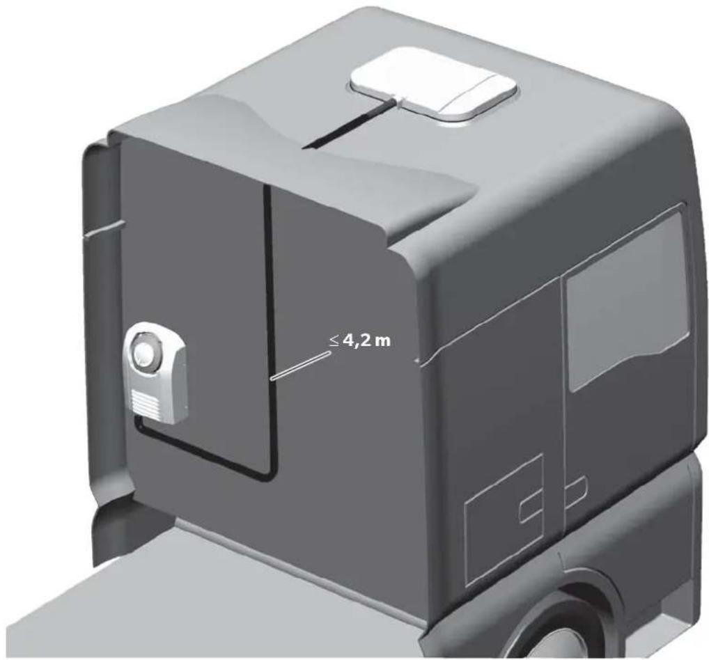
9
| bl br gl gr ro sw w | ||||||
| SL Modra Rjavo Rumena | Zelena ?Rdeče Čma Bela | |||||
Contents
1 Symbols and formats .... 10 2 Safety instructions .... 10
2.1 Using the device....11
2.1 Using the device....11
2.2 Handling electrical cables .....11
3 Conventions in this manual 12
3.1 General information on the installation manual.... 12 3.2 Target group.... 12 4 Intended use 12 5 Scope of delivery 13 6 Installation.... 14 6.1 Notes on installation.... 14 6.2 Removing the sunroof 15 6.3 Preparing the unit fastening 16 6.4 Attaching the seal for the cab roof.... 16 6.5 Installing the unit in the sunroof 16 6.6 Installing the electrical supply lines 17 6.7 Installing supply lines to the condenser unit 18 6.8 Fastening the cover frame 18
7 Configuration of unit software 19
7.1 Starting and ending configuration mode 19 7.2 Menu level 1: Set temperature....20 7.3 Menu level 2: Low voltage cut-off ..... 21 7.4 Menu level 3: Operating mode....22 7.5 Menu level 4: Default setting 23 7.6 Menu level 5: Temperature unit display ..... 23
8 Technical data....24
1 Symbols and formats

WARNING!
Safety instruction: Failure to observe this instruction can cause fatal or serious injury.

CAUTION!
Safety instruction: Failure to observe this instruction can lead to injury.

NOTICE!
Failure to observe this instruction can cause material damage and impair the function of the product.

NOTE
Supplementary information for operating the product.
2 Safety instructions
You must read the entire manual thoroughly and carefully.
We can only guarantee the reliability of the air conditioning roof unit if the instructions are adhered to. The same applies to the prevention of injury and damage to property.
The manufacturer accepts no liability for damage in the following cases:
- Faulty assembly or connection
- Damage to the product resulting from mechanical influences and incorrect connection voltage • Alterations to the product without express permission from the manufacturer
- Use for purposes other than those described in the operating manual
2.1 Using the device
- The freedom of movement of semi-trailers (of the outer edges of the semi-trailer when turning or jackknifing) and other vehicle attachments must not be restricted.
- Only use the air conditioning roof unit for the purpose specified by the manufacturer and do not make any alterations or structural changes to the device.
- Do not use the air conditioning roof unit if it is visibly damaged.
- The air conditioning roof unit must be installed safely so that it cannot tip over or fall down. • Installation, maintenance and repair work may only be carried out by qualified personnel from a specialist company who are familiar with the risks involved and the relevant regulations.
- Do not use the air conditioning roof unit near flammable fluids and gases.
- Do not operate the air conditioning roof unit if the ambient temperature is below 0°C.
- Do not undo the upper cover of the air conditioning roof unit in the event of a fire. Use approved extinguishing agents instead. Do not use water to extinguish fires.
- Please inquire from your vehicle manufacturer whether the height entered in your vehicle documentation needs to be altered due to the installation of the air conditioning roof unit (height: 75 mm).
- Disconnect all power supply lines when working on the air conditioning roof unit (cleaning, maintenance, etc).
2.2 Handling electrical cables
- Use cable ducts to lay cables through walls with sharp edges.
- Do not lay loose or bent cables next to electrically conductive materials (metal).
- Do not pull on the cables.
- Attach and lay the cables in such a manner that they cannot be tripped over or damaged.
- The electrical power supply may only be connected by a specialist workshop.
- Fit a fuse of 30 A directly on the battery connection.
- Never lay power supply lines (battery leads) in the vicinity of signal or control cables.
3 Conventions in this manual
3.1 General information on the installation manual
This installation manual contains the essential information and instructions for installing the air conditioning roof unit. The information contained is orientated towards the company installing the air conditioning roof unit.
The following instructions are intended to help you properly use the installation manual:
- The installation manual is part of the scope of delivery and should be stored carefully.
- The installation manual provides you with important information on the installation of the device and can also be used as a reference material in the event of repairs.
- The manufacturer assumes no liability for non-observance of this installation manual. Any claims are excluded in this case.
3.2 Target group
The installation and configuration information in this manual is intended for qualified installation personnel who are familiar with the guidelines and safety precautions to be applied during the installation of lorry accessory parts.
4 Intended use
The installation kit enables the installation of a CoolAir SP950T roof evaporator unit (ref. no. 9105305549) in a roof ventilation opening (hatch) provided at the plant in a MAN TGX, TGS (XXL, XLX, XL, LX) driver cab.
The CoolAir SP950T roof evaporator unit can only be operated in combination with a CoolAir SP950C condenser unit. Both components together form the CoolAir SP950 parking cooler.

NOTICE!
- The SP950 unit is not suitable for installation in construction machines, agricultural machines or similar equipment. It will not work properly if exposed to strong vibrations.
- Operating the SP950 unit with voltages other than those specified can result in damage to the device.

NOTE
The SP950 unit is only designed for ambient temperatures of up to 43 °C.
5 Scope of delivery
CoolAir SP950T installation kit for
MAN TGX, TGS (XXL, XLX, XL, LX)
Part designation Quantity Ref. no.
| Installation manual 1 4445102399 | ||
| 2.5 m insulating tape (profile: 10 x 20 mm) | 1 | 4443300055 |
| Spacer sleeve L = 18 mm, ∅ 14 mm | 8 | 4443900237 |
| Hex screw M8 x 45 8 4445200107 | ||
| Spring washer M8 8 4445200091 | ||
| Washer 8.4 x 20 8 4445200113 | ||
| MAN underlay strip | 4 4442500511 | |
| Connection cable 8 mm2 x 11 m | 1 | 4441300243 |
| Cable binder | 20 | 4445900256 |
| Cover frame | 1 | |
| Grey | 4443000333 | |
| Beige | 4443000483 | |
| Allen screw with cylindrical head M6 x 100 | 4 | 4445200092 |
| Washer M6 | 4 4445200115 | |
| Spacer sleeve L = 48 mm, ∅ 10 mm | 4 | 4443900241 |
| Spacer sleeve L = 40 mm, ∅ 10 mm | 4 | 4443900240 |
| Maxi Fuse holder | 1 | 4441600172 |
| Maxi Fuse 30 A | 1 4441550009 | |
| Ring terminal M8 | 1 | 4441500031 |
| Ring terminal M10 | 1 4441500032 | |
| Joint connector | 1 4441500033 | |
| Raised head screw M6 x 16 | 4 4445200154 | |
| Rivet nut M6 | 4 4445200153 | |
| Washer M8 | 8 4445200117 | |
6 Installation

NOTICE!
- The air conditioning roof unit may only be installed by qualified personnel from a specialist company. The following information is intended for technicians who are familiar with the guidelines and safety precautions to be applied.
- The manufacturer only assumes liability for parts included in the scope of delivery. The validity of the warranty expires if the device is installed together with third-party parts.
- Check whether the roof of the vehicle is able to support the weight of a person before climbing onto it. Ask the vehicle manufacturer about the permitted roof loads.
6.1 Notes on installation
These installation instructions must be read completely prior to the installation of the air conditioning roof unit.
The following tips and instructions must be observed while installing the air conditioning roof unit:

WARNING!
Make sure that all electrical components are electrically discharged before carrying out work on them!
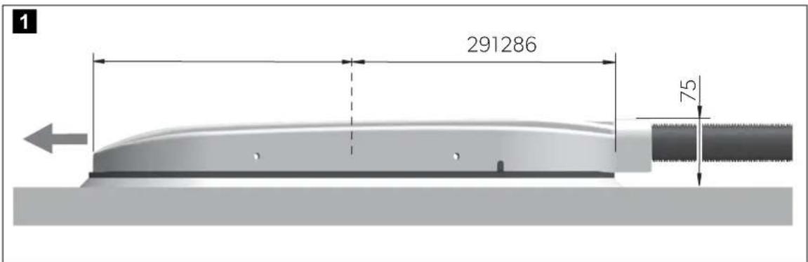
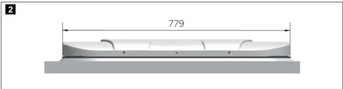
- Always check whether any vehicle components could be damaged or their operation impaired by the unit before installing the air conditioning roof unit. You can use fig. 1, page 3 and fig. 2, page 3 to check the dimensions of the installed unit. The dotted line indicates the middle of the sunroof opening.
- Before installation, find out (by consulting the manufacturer of the vehicle) whether the construction is designed for the static weight and the loads of the parking cooler when the vehicle is in motion. The manufacturer of the air conditioning roof unit assumes no liability whatsoever.
- The roof inclination of the mounting surface may not exceed 8° in the direction of travel.
- The supplied assembly parts must not be modified during installation.
- The ventilation slots (grill) may not be covered (minimum distance from other attachment parts: 10 cm).
- The unit must be connected directly to the battery.
- For installation and repair work, adhere to the corresponding rules of technology and the MAN installation guidelines.
- When installing the system and making the electrical connections, observe the guidelines from the body manufacturer.
- Pay attention to the connection plan for the device:
| No. in fig. 9, page 7 Designation | ||||||
| 1 Condensate pump | ||||||
| 2 | E | v | a | p | o | r |
| 3 Operating circuit board | ||||||
| 4 Temperature sensor | ||||||
| 5 Level sensor | ||||||
| 6 Control unit | ||||||
| 7 | 2 | 5 | A | f | u | s |
| 8 4 A fuse vaporiser fan | ||||||
| 9 4 A fuse condenser fan | ||||||
| 10 Condenser fan | ||||||
| 11 Compressor | ||||||
| 12 Klickson (compressor) | ||||||
a
e

WARNING!
Before installing the air conditioning roof unit, all connections to the battery of the vehicle must be disconnected.
Non-observance of this regulation can result in danger of electrocution.

CAUTION!
Improper installation of the air conditioning roof unit can result in irreparable damage to the device and put the safety of the user at risk.
The manufacturer will not be held liable for claims if the air conditioning roof unit is not installed according to this installation manual. That applies to malfunctions and the safety of the air conditioning roof unit, in particular to injuries and damage to property.

NOTE
After installing the unit, the specified parameters of the unit software must be checked (chapter "Configuration of unit software" on page 19).
6.2 Removing the sunroof
Remove all screws and fixtures of the existing sunroof. Take out the sunroof. Remove the sealant around the opening, so that the surface is clean and free of grease.

NOTE
Dispose of all waste material, glue, silicone, and seals separately. Observe local disposal guidelines.
6.3 Preparing the unit fastening
Enlarge the existing 6.5 mm diameter drill holes for fastening the sunroof to a diameter of 8.5 mm (fig. 4 5, page 4).
6.4 Attaching the seal for the cab roof

NOTICE!
Ensure that the adhesive surface for the seal between the unit and the cab roof is clean (free of dust, oil, etc.).
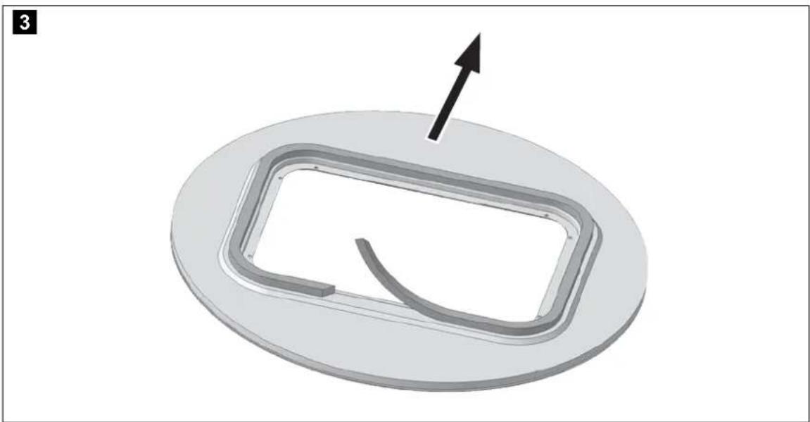
Stick the 2.5 m insulating tape (35 x 20 mm) to the cab roof, following the outline of the sunroof opening (fig. 3, page 3). Provide the abutting edge and the top edge of the insulating tape with an unhardened plastic butyl sealing compound (e.g., SikaLastomer-710).
6.5 Installing the unit in the sunroof
Set the unit down centrally aligned and in the direction of travel (fig. 1, page 3) on the sunroof opening.

NOTE
Make sure the air conditioning roof unit is centered perfectly. The seal must be applied continuously around the air conditioning roof unit after being placed on the roof of the vehicle. This is the only way to ensure a tight seal.
Place the spacer sleeve L = 40 mm, diameter 14 mm (fig. 4 1, page 4) and the washer 8.4 x 20 (fig. 4 11, page 4) on the fastening drill holes as shown in fig. 4, page 4. Use the underlay strips supplied (fig. 4 2, page 4) for fastening the unit. Screw one hex screw M8 x 60 mm (fig. 4 5, page 4) with a washer (fig. 4 3, page 4) and spring washer (fig. 4 4, page 4) into the 8 thread inserts on the bottom of the unit.

NOTICE!
Do not exceed the specified torque under any circumstances. This is the only way to ensure that the thread inserts are not torn out.
Tighten the screws with a torque of 8 Nm.
6.6 Installing the electrical supply lines

WARNING!
- The electrical power supply may only be performed by qualified personnel with specialist knowledge.
- Make sure there is no voltage present on electrically operated components before carrying out work on them!

NOTICE!
- Fit a fuse of 25 A to the connection to the vehicle's power supply.
- The battery must be able to supply the required current and voltage (chapter "Technical data" on page 24).

NOTE
The connection must be made directly to the battery.
Plug the cable strand for the power supply into the unit and run it through the overhead cupboard on the right to the A pillar. ▶ Run the cable strand down to the central electrics (preferably along the roof hatch drain hose) and the mounting interface to the outside. ▶ Lay the positive and negative cables for the battery box in a protected place. ▶ Trim the negative cable (black) to length if necessary and attach an appropriate ring terminal. ▶ Connect the negative cable (black) directly to the negative terminal of the battery.

NOTE
Place the fuse holder no more than 0.3 m from the positive terminal of the battery.
▶ Attach the fuse holder in a suitable location. ▶ Lay the positive cable (red) to the fuse holder and trim. ▶ Trim the shorter connection cable from the fuse holder to the correct length and connect with a joint connector on the positive cable (red). ▶ Insulate the connection cable with the joint connectors properly. ▶ Trim the longer connection cable from the fuse holder if necessary and fit a suitable ring terminal. ▶ Connect the longer connection cable from the fuse holder with the ring terminal directly to the positive terminal of the battery.
6.7 Installing supply lines to the condenser unit
Observe the following instructions when installing the supply lines:
- Also observe the installation instructions for the condenser unit.
- The maximum cable length between the evaporator and condenser unit is 4.20 m (fig. 5, page 4).
- When installing and bending supply lines, avoid narrow radii. Use a suitable round object as a bending aid. A radius which is too narrow will buckle the refrigerant line, and the parking cooler will be inoperable.
▶ Shorten any supply line which is not needed by bending a curve.
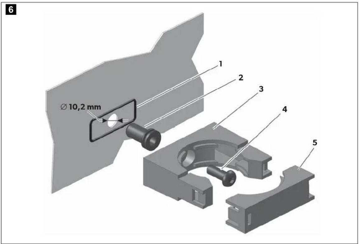
▶ Apply packing compound (fig. 6 1, page 5) to prevent water entering between the rear wall of the truck and the clip.

NOTE
If you wish to avoid damaging the rear wall of the truck (drilling a hole), you can also apply the clip using a suitable adhesive. Observe the instructions provided by the adhesive manufacturer.
Fasten the supply line onto the rear wall of the truck using the clips as follows (fig. 6, page 5):
▶ Drill a hole of ∅ 10.2 mm for each clip. ▶ Fasten the rivet nut M6 (2). ▶ Apply sealant (1) to prevent any water from getting between the rear wall of the truck and the clip. ▶ Screw the clip with the raised head screws M6 x 16 (4) into the rivet nut. ▶ Insert the corrugated piping in the holder provided (3). ▶ Put the cover on (5).
6.8 Fastening the cover frame

NOTICE!
Screw the screws in carefully order not to damage the cover frame.
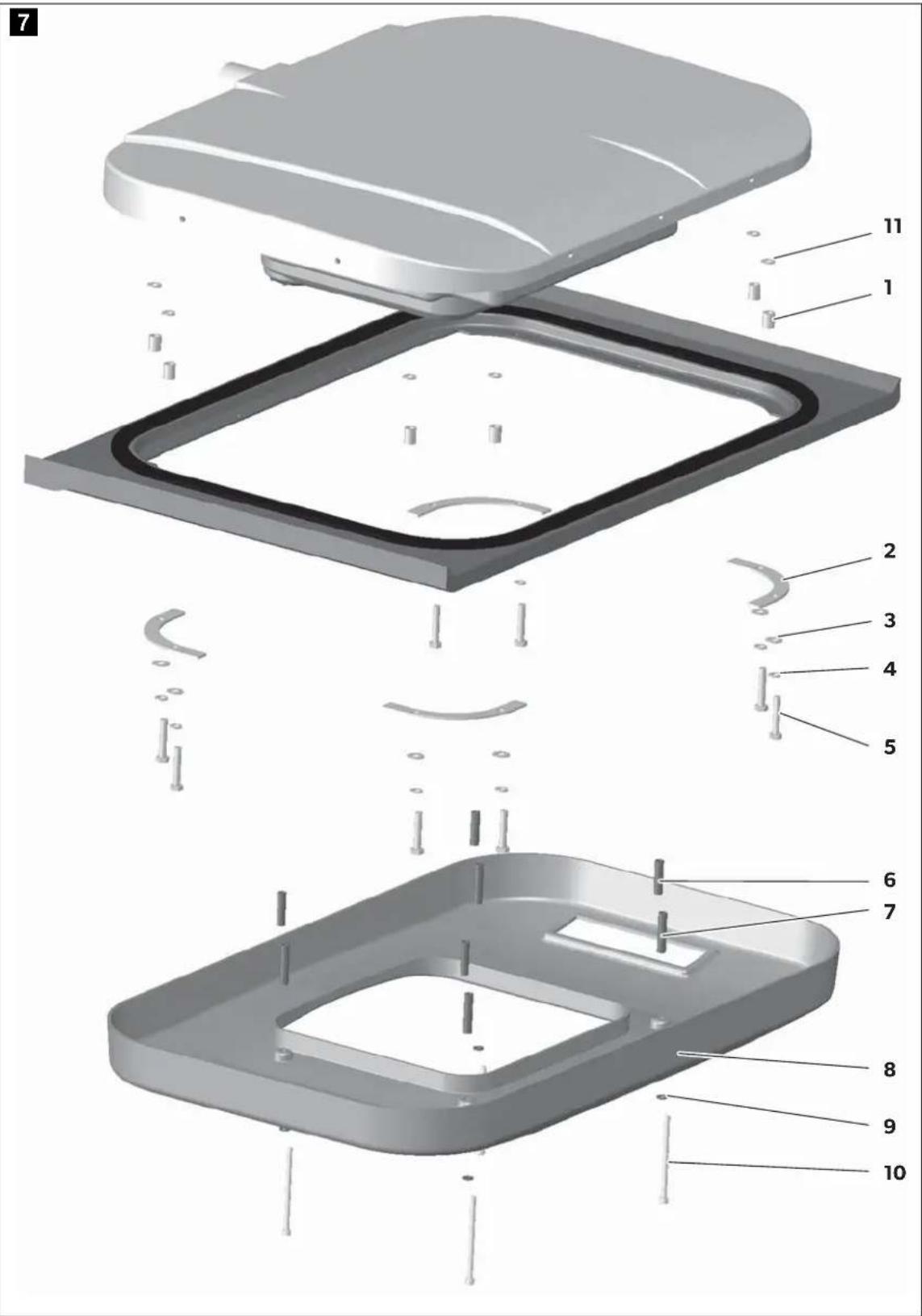
See fig. 7, page 6
▶ Fasten the cover frame (8) to the unit with the four cylindrical screws (10), washers (9) and the eight spacer sleeves (L = 40 mm, ∅ 10 mm: 6; L = 48 mm, ∅ 10 mm: 7). The spacer sleeves keep the cover frame apart from the unit.
7 Configuration of unit software
Before you first start up the unit, the controls can be adapted to suit the installation conditions. This must be done by the person installing the unit.
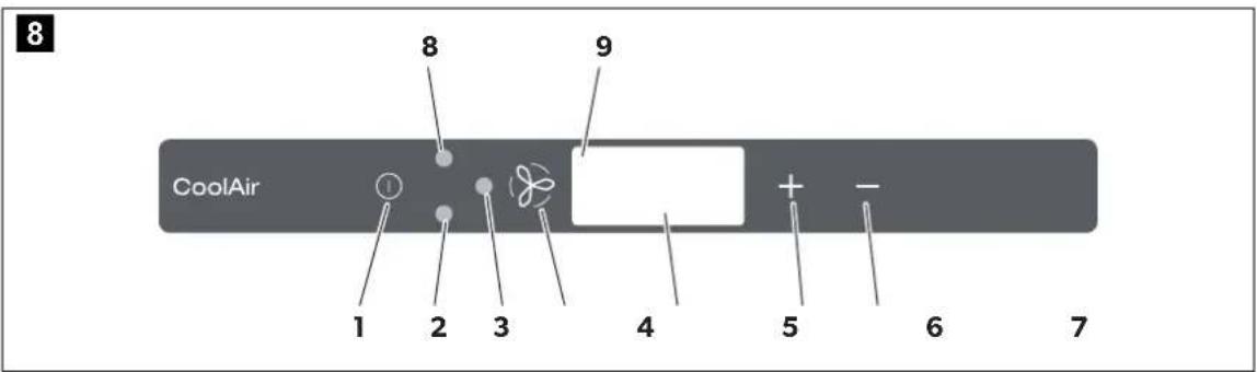
In configuration mode, the following unit software parameters must be set at the control panel (fig. 8, page 7).
| Menu level | Parameter Meaning | Default setting | ||
| 1 | Set temperature | The unit starts at the temperature defined here. | 20 °C (68 °F) | |
| 2 | L o w cut-off | The battery monitor shuts down the unit at the voltage defined here. | Characteristic figure 4 = 22,8 V | |
| 3 | Operating mode | The unit starts with the operating mode defined here. | 0 = Automatic mode | |
| 4 | Default settings | Parameters 1 – 3 can be reset to the default settings. | -- | |
| 5 | Te m p display | The temperature can be displayed in °C or °F. | °C n i t | |

NOTE
Configuration mode can still be activated if the undervoltage protection mechanism has switched off the unit and only residual voltage is available.
7.1 Starting and ending configuration mode
The adjustable parameters can be changed in configuration mode:
When using the ① button to switch on the unit, hold both buttons + and - pressed until the compressor LED flashes. √You are now in configuration mode. √ The display version (e.g. "3.1S") appears in the display for 2 seconds. √The first digit of the display shows the menu level and the second and third digits show the parameters which can be set, e.g. 1.17 for menu level 1 and a set target value of 17 °C.

NOTE
If you make no entry on the control panel for 60 seconds, the unit quits configuration mode and shuts down.
▶Press the button to quit configuration mode.
7.2 Menu level 1: Set temperature
The unit always starts with a defined value for the room temperature. This parameter can be configured between 17 and 30 °C (62 and 86 °F).
▶ Start configuration mode (chapter "Starting and ending configuration mode" on page 19).
√The first digit of the display shows the menu level and the second and third show the parameter which can be set.
▶Press the button to change the parameters.
▶ Use the + and - buttons to select the target value (in °C) at which the unit should start operation.
√ The digits in the display flash until the parameter you entered is confirmed.
▶ Press the button to confirm your entry.
√ The set value is saved and is then used when the unit is restarted.
√ You are now in menu level 1 again and can use the + and - buttons to switch between menu levels.
7.3 Menu level 2: Low voltage cut-off
The battery monitor protects the battery from excessive discharging.

NOTICE!
When the battery monitor switches the device off, the battery only has part of its charging capacity. Avoid starting repeatedly or operating electrical consumers. Make sure that the battery is recharged. As soon as the required voltage is available again, the unit can be operated again.
If only the set power supply is available here for the air conditioning roof unit, the unit is switched off.
▶ Start configuration mode (chapter "Starting and ending configuration mode" on page 19). √ The first digit of the display shows the menu level and the second and third show the parameter which can be set. ▶ Press the + button once to switch to menu level 2. ▶ Press the button to change the parameter. √ The digits in the display flash until the parameter you entered is confirmed. ▶ Use the + and - buttons to set the value for low voltage shutdown. The characteristic figures at second and third place on the display represent the voltage (V) at which the unit is shut down:
| Characteristic figure | Low voltage shutdown |
| 122.2 623.0 | |
| 222.4 723.1 | |
| 322.6 823.2 | |
| 422.8 923.4 | |
| 5 | 22.9 |
| Characteristic figure | Low voltage shutdown |
| 10 | 23.6 |
▶ Press the button to confirm your entry. √ The set value is saved and is then used when the unit is restarted. √ You are now in menu level 2 again and can use the + and - buttons to switch between menu levels.
7.4 Menu level 3: Operating mode
The unit always starts with a defined operating mode for room temperature. This parameter can be configured:
▶ Start configuration mode (chapter "Starting and ending configuration mode" on page 19). √ The first digit of the display shows the menu level and the second and third show the parameter which can be set. ▶ Press the + button twice to switch to menu level 3. ▶ Press the button to change the parameters. √ The digits in the display flash until the parameter you entered is confirmed. ▶ Use the + and - buttons to set the mode with which the unit starts up:
| Characteristic figure | Operating mode |
| Automatic mode | |
| Operating mode 1 | |
| Operating mode 2 | |
| Operating mode 3 |
Press the button to confirm your entry. The set value is saved and is then used when the unit is restarted. You are now in menu level 3 again and can use the + and - buttons to switch between menu levels.
7.5 Menu level 4: Default setting
You can reset the parameters you set in configuration mode on menu levels 1 to 3 to the default settings:
Start configuration mode (chapter "Starting and ending configuration mode" on page 19). The first digit of the display shows the menu level and the second and third show the parameter which can be set. Press the + button three times to switch to menu level 4. The display shows --. Press the button to reset the unit to the factory settings. -- flashes in the display. Press the + button. The display shows 00. Press the button to confirm your entry. The parameters set in configuration mode are reset to the default setting. You are now in menu level 4 and can use the + and - buttons to switch between menu levels.
7.6 Menu level 5: Temperature unit display
The system can display the room temperature in °C or °F. This parameter can be configured:
Start configuration mode (chapter "Starting and ending configuration mode" on page 19). The first digit of the display shows the menu level and the second and third show the parameter which can be set. Press the + four times to switch to menu level 5. Press the button to change the parameters. The digits in the display flash until the parameter you entered is confirmed. Use the + and - buttons to select the temperature unit that the system should display. Press the button to confirm your entry. The set value is saved and is then used when the unit is restarted. You are now in menu level 5 again and can use the + and - buttons to switch between menu levels.
8 Technical data
| CoolAir SP950 parking cooler with SP950T roof evaporator unit | |
| Ref. number: 9105305549 | |
| Cooling capacity: 850 W | |
| Rated input voltage: 24 V--- | |
| Input voltage range: | 22.5 V--- - 30 V--- |
| Max. current consumption: 22 A | |
| Low voltage shutdown: Configurable (chapter “Menu level 2: Low voltage cut-off” on page 21) | |
| Refrigerant: R-134a | |
| Refrigerant quantity: 60 g | |
| CO2 equivalent: 0,858 t | |
| Global warming potential (GWP): | 1430 |
| Dimensions (L x B x H in mm)Evaporator unit:Condenser unit: | 577 x 779 x 178 mm156 x 346 x 490 mm |
| Weight:Evaporator unit:Condenser unit: | approx. 15 kgapprox. 12 kg |
Contains fluorinated greenhouse gases
Hermetically sealed equipment
6.1 Installation information....155
6.2 Removing the tailgate....157
Dometic Australia Pty. Ltd.
1 John Duncan Court
Varsity Lakes QLD 4227
+61755076000
+61755076001
Mail: sales@dometic-waeco.com.au
AUSTRIA
Dometic Austria GmbH
Neudorferstraße 108
A-2353 Guntramsdorf
+43 2236 908070
+43 2236 90807060
Mail: info@dometic.at
BENELUX
Dometic Branch Office Belgium
Lourdesstraat 84 B
B-8940 Geluwe
+32 2 3598040
+32 2 3598050
Mail: info@dometic.be
DENMARK
Dometic Denmark A/S
Nordensvej 15, Taulov
DK-7000 Fredericia
+45 75585966
+45 75586307
Mail: info@dometic.dk
FINLAND
Dometic Finland OY
Mestarintie 4
FIN-01730 Vantaa
+358 20 7413220
Mail: info@dometic.fi
FRANCE
Dometic SAS
Dometic Group Asia Pacific
Suites 2207-11 - 22/F, Tower 1
The Gateway · 25 Canton Road,
Tsim Sha Tsui - Kowloon
+852 2 4611386
+85224665553
Mail: info@waeco.com.hk
HUNGARY
Dometic Zrt. Sales Office
Kerékgyártó u. 5
H-1147 Budapest
+3614684400
+3614684401
Dometic Italy S.r.l.
Via Virgilio, 3
I-47122 Forli (FC)
+39 0543 754901
+39 0543 754983
Mail: vendite@dometic.it
JAPAN
Dometic KK
Maekawa-Shibaura, Bldg. 2
2-13-9 Shibaura Minato-ku
Tokyo 108-0023
+81354453333
+81354453339
Mail: info@dometic.jp
MEXICO
Circuito Médicos No. 6 Local 1
Colonia Ciudad Satélite
CP 53100 Naucalpan de Juárez
Estado de México
+52 55 5374 4108
+52 55 5393 4683
Mail: info@dometic.com.mx
NETHERLANDS
Dometic Benelux B.V.
Ecustraat 3
NL-4879 NP Etten-Leur
+31 76 5029000
+31 76 5029019
Mail: info@dometic.nl
NEW ZEALAND
Dometic New Zealand Ltd.
PO Box 12011
Penrose
Auckland 1642
+6496221490
Fax +6496221573
Mail: customerservices@dometic.co.nz
NORWAY
Dometic Norway AS
Østerøyveien 46
N-3232 Sandefjord
+47 33428450
+47 33428459
Mail: firmapost@dometic.no
POLAND
Dometic Poland Sp. z o.o.
Ul. Puławska 435A
PL-02-801 Warszawa
+48 22 414 3200
+48 22 414 3201
Mail: info@dometic.pl
PORTUGAL
Dometic Spain, S.L.
Komsomolskaya square 6-1
RU-107140 Moscow
+7 495 780 79 39
+7 495 916 56 53
Mail: info@dometic.ru
SINGAPORE
Dometic Pte Ltd
18 Boon Lay Way
06-141 Trade Hub 21
Singapore 609966
+65 6795 3177
Fax: +65 6862 6620
Mail: dometic.sg@dometic.com
SLOVAKIA
Dometic Slovakia s.r.o.
Sales Office Bratislava
Nádražná 34/A
900 28 Ivánka pri Dunaji
Tel: +421245529680
Mail: bratislava@dometic.com
SOUTH AFRICA
Dometic (Pty) Ltd.
Regional Office
South Africa & Sub-Saharan Africa
2 Avalon Road
West Lake View Ext 11
Modderfontein 1645
Johannesburg
+27873530380
Mail: info@dometic.co.za
SPAIN
Dometic Spain S.L.
Avda. Sierra del Guadarrama, 16
E-28691 Villanueva de la Cañada
Madrid
+34 918 336 089
+34 900 100 245
Mail: info@dometic.es
SWEDEN
Dometic Scandinavia AB
Gustaf Melins gata 7
Dometic Switzerland AG
Riedackerstrasse 7a
CH-8153 Rümlang
+41 44 8187171
+41 44 8187191
Mail: info@dometic.ch
UNITED ARAB EMIRATES
Dometic Middle East FZCO
P.O. Box 17860
S-D 6, Jebel Ali Freezone
Dubai
+971 4 883 3858
+971 4 883 3868
Email: info@dometic.ae
UNITED KINGDOM
Dometic UK Ltd.
Dometic House, The Brewery
Blandford St. Mary
Dorset DT11 9LS
+44 344 626 0133
+44 344 626 0143
Mail: customerservices@dometic.co.uk
USA
Dometic RV Division
1120 North Main Street
Elkhart, IN 46515
+1574-264-2131


- CONTENTS
- SYMBOLS AND FORMATS
- WARNING
- CAUTION
- NOTICE
- NOTE
- SAFETY INSTRUCTIONS
- USING THE DEVICE
- HANDLING ELECTRICAL CABLES
- CONVENTIONS IN THIS MANUAL
- GENERAL INFORMATION ON THE INSTALLATION MANUAL
- TARGET GROUP
- INTENDED USE
- SCOPE OF DELIVERY
- INSTALLATION
- NOTES ON INSTALLATION
- REMOVING THE SUNROOF
- PREPARING THE UNIT FASTENING
- ATTACHING THE SEAL FOR THE CAB ROOF
- INSTALLING THE UNIT IN THE SUNROOF
- INSTALLING THE ELECTRICAL SUPPLY LINES
- INSTALLING SUPPLY LINES TO THE CONDENSER UNIT
- FASTENING THE COVER FRAME
- SEE FIG. 7, PAGE
- CONFIGURATION OF UNIT SOFTWARE
- STARTING AND ENDING CONFIGURATION MODE
- MENU LEVEL 1: SET TEMPERATURE
- MENU LEVEL 2: LOW VOLTAGE CUT-OFF
- MENU LEVEL 3: OPERATING MODE
- MENU LEVEL 4: DEFAULT SETTING
- MENU LEVEL 5: TEMPERATURE UNIT DISPLAY
- TECHNICAL DATA
- DOMETIC AUSTRALIA PTY. LTD
- AUSTRIA
- DOMETIC AUSTRIA GMBH
- BENELUX
- DOMETIC BRANCH OFFICE BELGIUM
- DENMARK
- DOMETIC DENMARK A/S
- FINLAND
- DOMETIC FINLAND OY
- FRANCE
- DOMETIC SAS
- DOMETIC GROUP ASIA PACIFIC
- HUNGARY
- DOMETIC ZRT. SALES OFFICE
- DOMETIC ITALY S.R.L
- JAPAN
- DOMETIC KK
- MEXICO
- NETHERLANDS
- DOMETIC BENELUX B.V
- NEW ZEALAND
- DOMETIC NEW ZEALAND LTD
- NORWAY
- DOMETIC NORWAY AS
- POLAND
- DOMETIC POLAND SP. Z O.O
- PORTUGAL
- DOMETIC SPAIN, S.L
- SINGAPORE
- DOMETIC PTE LTD
- SLOVAKIA
- DOMETIC SLOVAKIA S.R.O
- SOUTH AFRICA
- DOMETIC (PTY) LTD
- SPAIN
- DOMETIC SPAIN S.L
- SWEDEN
- DOMETIC SCANDINAVIA AB
- DOMETIC SWITZERLAND AG
- UNITED ARAB EMIRATES
- DOMETIC MIDDLE EAST FZCO
- UNITED KINGDOM
- DOMETIC UK LTD
- USA
- DOMETIC RV DIVISION
Brand : DOMETIC
Model : MagicSpeed CBI 200
Category : Air conditioner