
BRIGGS & STRATTON 071002 - Engine BRIGGS & STRATTON - Free user manual and instructions
Find the device manual for free BRIGGS & STRATTON 071002 BRIGGS & STRATTON in PDF.

| Product Type | Manual Transfer Switch |
| Brand | Briggs & Stratton |
| Model | 071002 |
| Enclosure | NEMA I (indoor) |
| Rated Voltage | 250 V AC |
| Rated Current | 60 A |
| Poles | 2 |
| Fault Capacity | 10,000 A symmetrical RMS |
| Weight | 15.4 kg (34 lb) |
| Supply | Utility Supply and Generator Supply |
| Integrated Circuit Breakers | 2-pole 60 A circuit breakers |
| Interlock | Mechanical (prevents simultaneous operation) |
| Usage | Indoor only |
| Compatibility | Briggs & Stratton residential standby generators |
| Warranty | 3 years for residential use |
| Installation | By a qualified electrician, in accordance with local codes |
| Maintenance | Periodic check of connections and operation |
| Safety | Grounding required; do not use if cables are damaged |
| Spare Parts | Contact an authorized service center |
Frequently Asked Questions - BRIGGS & STRATTON 071002 BRIGGS & STRATTON
User questions about BRIGGS & STRATTON 071002 BRIGGS & STRATTON
0 question about this device. Answer the ones you know or ask your own.
Ask a new question about this device
Download the instructions for your Engine in PDF format for free! Find your manual BRIGGS & STRATTON 071002 - BRIGGS & STRATTON and take your electronic device back in hand. On this page are published all the documents necessary for the use of your device. BRIGGS & STRATTON 071002 by BRIGGS & STRATTON.
USER MANUAL BRIGGS & STRATTON 071002 BRIGGS & STRATTON
Installation & Owner's Manual
Questions? Help is just a moment away!
Preguntas? Laapiaesjusta unmomentolejos!
Manual Transfer Switch
Briggs & Stratton
POWERPRODUCTS
TABLE OF CONTENTS
TABLE OF CONTENTS 2
SAFETY RULES 3
INTRODUCTION. 4
For the Home or Business Owner: 4
For the Installing Dealer/Contractor: 4
Owner Orientation 4
Installer Responsibilities 4
Equipment Description. 5
INSTALLATION. 5
Unpacking. 5
Delivery Inspection 5
Shipment Contents 5
Mounting Dimensions 5
ESSENTIAL CIRCUIT ISOLATION 6
Mounting Instructions 7
Power Wiring Interconnections 7-8
SYSTEM OPERATION. 9
Specifications. 9
Model 071002 9
Model 071003 9
When Calling The Factory 9
SERVICE PARTS 10
NOTES 11-12
WARRANTY 13
SAFETY RULES

This is the safety alert symbol. It is used to alert you to potential personal injury hazards. Obey all safety messages that follow this symbol to avoid possible injury or death.
The safety alert symbol (▲) is used with a signal word (DANGER, CAUTION, WARNING), a pictorial and/or a safety message to alert you to hazards. DANGER indicates a hazard which, if not avoided, will result in death or serious injury. WARNING indicates a hazard which, if not avoided, could result in death or serious injury.
CAUTION indicates a hazard which, if not avoided, might result in minor or moderate injury. CAUTION, when used without the alert symbol, indicates a situation that could result in equipment damage. Follow safety messages to avoid or reduce the risk of injury or death.
The manufacturer cannot possibly anticipate every possible circumstance that might involve a hazard. The warnings in this manual, and the tags and decals affixed to the unit are, therefore, not all-inclusive. If you use a procedure, work method or operating technique that the manufacturer does not specifically recommend, you must satisfy yourself that it is safe for you and others. You must also make sure that the procedure, work method or operating technique that you choose does not render the transfer switch unsafe.

WARNING
Only qualified electricians should attempt installation of this system, which must strictly comply with applicable codes, standards and regulations.

WARNING

Failure to properly ground transfer switch can result in electrocution.
- DO NOT touch bare wires or receptacles.
- DO NOT use transfer switch with worn, frayed, bare or otherwise damaged wiring.
- DO NOT handle electrical cords while standing in water, while barefoot, or while hands or feet are wet.
- If you must work around a unit while it is operating, stand on an insulated dry surface to reduce shock hazard.
- DO NOT allow unqualified persons or children to operate or service transfer switch.
- In case of an accident caused by electrical shock, immediately shut down the source of electrical power and contact the local authorities. Avoid direct contact with the victim.
CAUTION
Improper treatment of transfer switch can damage it and shorten its life.
- Use transfer switch only for intended uses.
- If you have questions about intended use, ask dealer or contact Briggs and Stratton Power Products.
- DO NOT expose transfer switch to excessive moisture, dust, dirt, or corrosive vapors.
- Despite the safe design of the transfer switch, operating this equipment imprudently, neglecting its maintenance or being careless can cause possible injury or death.
- Remain alert at all times while working on this equipment. NEVER work on the equipment when you are physically or mentally fatigued.
- If connected devices overheat, turn them off and turn off their circuit breaker/fuse.
INTRODUCTION
Thank you for your purchase of this Briggs & Stratton Power Products Manual Transfer Switch. This product is intended for use with Briggs & Stratton Home Standby Generator sets ONLY. This is an optional home standby system which provides an alternate source of electric power and to serve loads such as heating, refrigeration systems, and communication systems that, when stopped during any power outage, could cause discomfort or the like. This product DOES NOT qualify for emergency standby as defined by NFPA 70 (NEC).
Briggs and Stratton Power Products (BSPP) has made every effort to provide for a safe, streamlined and cost-effective installation. Each installation is unique; it is impossible for BSPP to know and advise of all conceivable procedures and methods by which installation might be performed, nor the potential hazards associated with those methods. For these reasons,
Only licensed electrical contractors should install transfer switches. Installations must strictly comply with all applicable federal, state and local codes, standards and regulations.
Your BSPP Transfer Switch is supplied with this combined "Installation and Owner's Manual". This is an important document and should be retained by the owner after the installation has been completed.
Every effort has been expended to make sure that the information in this manual is both accurate and current. However, the manufacturer reserves the right to change, alter or otherwise improve the system at any time without prior notice.
For the Home or Business Owner
To help you make informed choices and communicate effectively with your installation contractor(s),
Read and understand the Owner Orientation Section of this manual BEFORE contracting or starting your transfer switch installation.
To arrange for proper installation, contact the store at which you purchased your BSPP Transfer Switch, your dealer, or your utility power provider.
The Transfer Switch Warranty is VOID unless the system is installed by a licensed electrical professional.
For the Installing Dealer/Contractor
Check federal, state and local codes for questions on installation.
If you need more information about the transfer switch, call 1-800-743-4115, between 8:00 AM and 5:00 PM CT.
Owner Orientation
The illustrations are for typical circumstances and are meant to familiarize you with the installation options available with your transfer switch.
Local codes, appearance, and distances are the factors that must be considered when negotiating with an installation professional. As the distance from the existing electrical service increases, compensation in wiring materials must be allowed for. This is necessary to comply with local codes and overcome electrical voltage drops.
The factors mentioned above will have a direct effect on the overall price of your transfer switch installation.
NOTE: Your installer must check local codes AND obtain permits before installing the system.
- Read and follow the instructions given in this manual.
- Follow a regular schedule in caring for and using your transfer switch, as specified in the manual.
Installer Responsibilities
- Read and observe the safety rules.
- Read and follow the instructions given in this manual.
- Check federal, state and local codes.
Equipment Description
These transfer switches are intended to operate compatible electrical loads of normal residential installations. The load is connected either to utility power (normal) or home standby power (emergency).
These manual transfer switches are equipped with two circuit breakers ("GENERATOR SUPPLY" and "UTILITY SUPPLY") and a mechanical interlock. The "GENERATOR SUPPLY" circuit breaker provides power from the generator to the load devices wired to the manual transfer switch. The "UTILITY SUPPLY" circuit breaker provides utility power from the distribution panel to the load devices wired to the manual transfer switch.
The mechanical interlock allows the circuit breakers for either the generator power "GENERATOR SUPPLY" or the utility power "UTILITY SUPPLY" to be turned on to provide power to the selected house loads. These manual transfer switches will not allow utility line power and generator power to be connected to a load device at the same time.
If utility line power is restored while generator power is being used, there will be no affect on the generator or transfer switch components. When utility power is restored, follow the instructions in the section "System Operation".
INSTALLATION
Unpacking
Delivery Inspection
After removing the carton, carefully inspect the transfer switch components for any damage that may have occurred during shipment.
IMPORTANT: If loss or damage is noted at time of delivery, have the person(s) making delivery note all damage on the freight bill and affix his signature under the consignor's memo of loss or damage. If loss or damage is noted after delivery, contact the carrier for claim procedures. Freight damaged parts are not warranted.
Shipment Contents
- Manual Power Transfer Switch
Installation and Owner's Manual
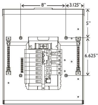
Mounting Dimensions
Figure I depicts the physical size and mounting hole locations of the manual transfer switch enclosure. The transfer switch enclosure is commonly secured through the predrilled holes, as shown.
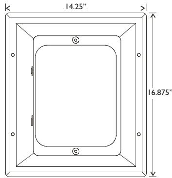
Figure I — Manual Power Transfer Switch Dimensions
Enclosure Dimensions
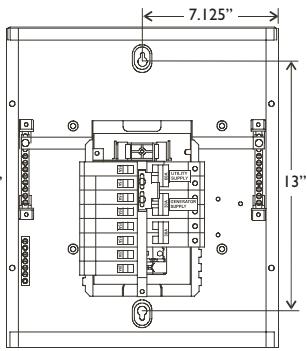
Mounting Dimensions
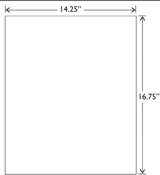
Model 071002
Enclosure Dimensions
Mounting Dimensions
Model 071003
ESSENTIAL CIRCUIT ISOLATION
Essential electrical loads are loads that will be powered by the Standby Generator System. Essential loads are grouped together and wired into the transfer switch.

TO THE INSTALLER: Consult with Standby Generator System owner(s) to discuss their "Selection of Essential Circuits", described in owner's manual.
Ensure that the total of the selected load circuits fed by this transfer switch are within the generator's rated capacity.
The following requirements apply to this type of isolation system:
- The Manual Transfer Switch is installed after the main distribution panel.
- The Manual Transfer Switch has a load rating of 60 Amps. This is the maximum load rating of the essential loads.
All wiring must conform to national, state and local codes.
The illustration in Figure 2 depicts the Standby Generator System and assumes the utility is supplying 120/240 Volt , single-phase electrical service.
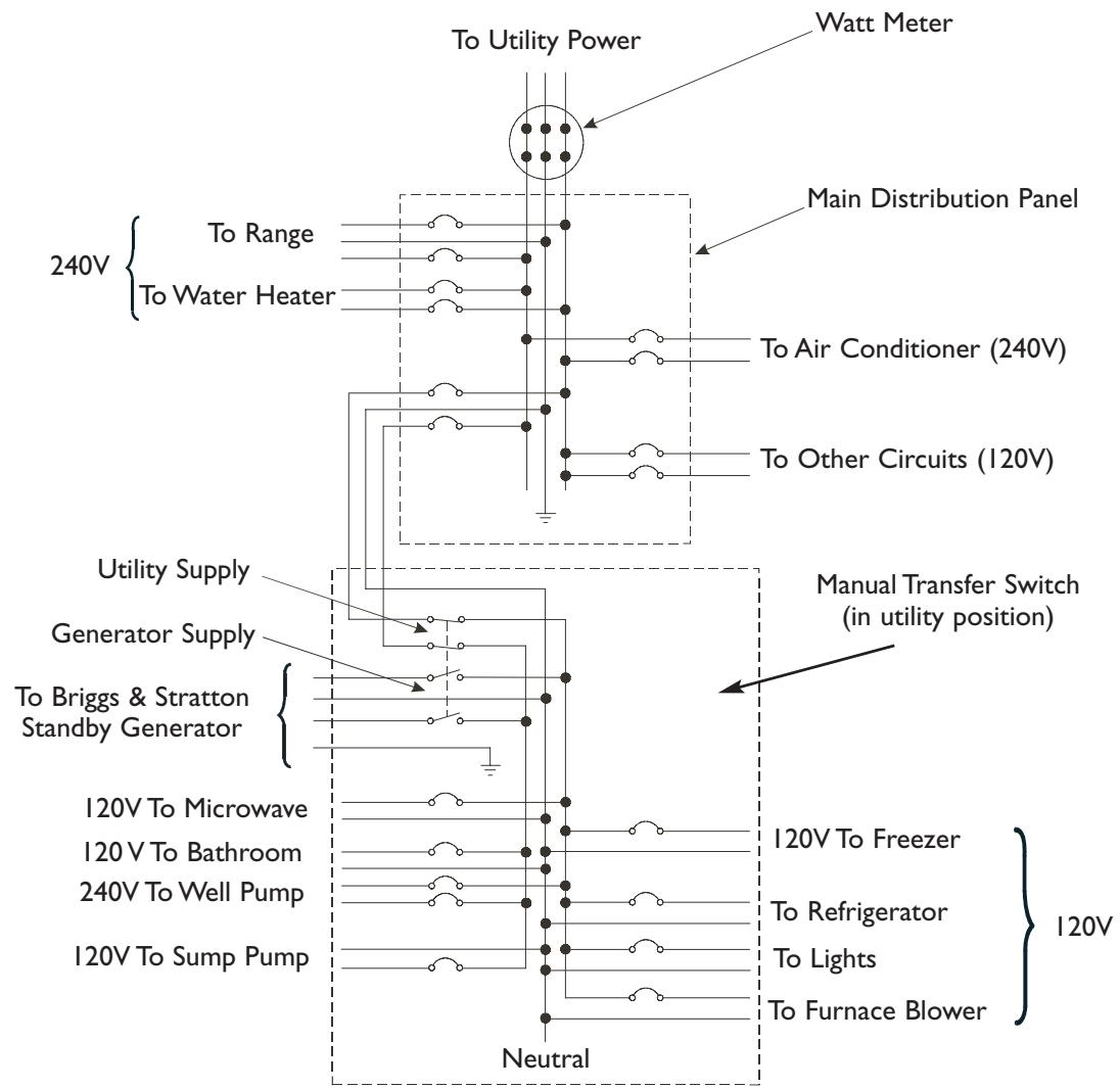
Figure 2 —Typical System Diagram with Essential Circuits
Mounting Guidelines
The Model 071002 Manual Transfer Switch is enclosed in a NEMA Type I enclosure suitable for indoor use only.
The Model 071003 Manual Transfer Switch is enclosed in a NEMA Type 3R enclosure suitable for indoor/outdoor use.
Guidelines for mounting the Manual Transfer Switch include:
- Model 071003 Manual Transfer Switch must be installed with minimum NEMA 3R hardware for conduit connections.
- Install the switch on a firm, sturdy supporting structure.
- To assure easy insertion or removal of circuit breakers, level and plumb the enclosure. This can be done by placing washers between the switch enclosure and the mounting surface.
- NEVER install the switch where any corrosive substance might drip onto the enclosure.
- Protect the switch at all times against excessive moisture, dust, dirt, lint, construction grit and corrosive vapors.
The typical installation of the Manual Power Transfer Switch is depicted in Figure 3. Discuss layout suggestions/changes with the owner before beginning the system installation process.
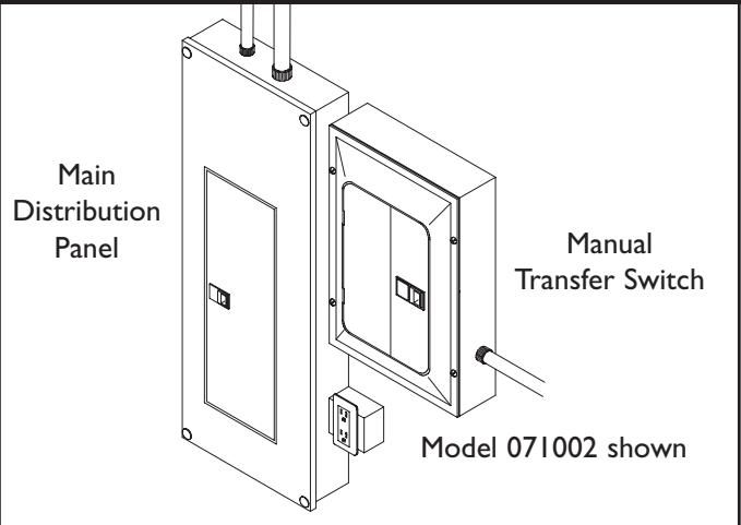
Figure 3 — Typical Switch Mounting
Power Wiring Interconnections
All wiring must be the proper size, properly supported, of approved insulation qualities, and protected by NEC approved conduit.
Complete the following connections between the generator, transfer switch and main distribution panel (Figure 4, on next page).
- Connect utility power supply leads from two pole breaker installed in main distribution panel to transfer switch two pole breaker marked "UTILITY SUPPLY". A 60 Amp circuit breaker is provided. Ensure breaker is turned OFF.
- Connect main distribution panel ground to transfer switch "GND" bus.
- Connect main distribution panel neutral lead to transfer switch "NEUTRAL" terminal.
- Connect generator power supply leads from generator's control panel to transfer switch two pole breaker marked "GENERATOR SUPPLY".
- Connect generator Neutral from control panel to transfer switch "NEUTRAL" terminal.
- Connect generator "GND" from control panel to transfer switch "GND" terminal.
- Tighten all wire connections/fasteners to proper torque.
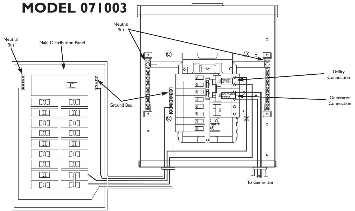
Figure 4 —A Typical Installation Diagram for Transfer Switch
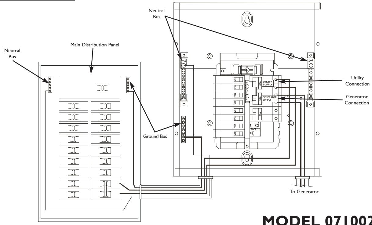
MODEL 071002
SYSTEM OPERATION
To transfer from utility power to generator power:
I. Turn OFF main breaker labeled "UTILITY SUPPLY".
2. Turn OFF all branch circuit breakers in transfer switch.
3. Slide mechanical interlock and turn "GENERATOR SUPPLY" breaker to ON position.
4. Turn ON branch circuit breakers one at a time.
To transfer from generator power back to utility power:
I. Turn OFF main breaker labeled "GENERATOR SUPPLY".
2. Turn OFF all branch circuit breakers in transfer switch.
3. Slide mechanical interlock and turn "UTILITY SUPPLY" breaker to ON position.
4. Turn ON branch circuit breakers one at a time.
Specifications
UL® 1008 Listed Transfer Switch
Model 071002
Enclosure. NEMA I
Maximum Load/Circuit:
from Load Center 60 Amps
Rated AC Voltage. 250 Volts
Poles 2
Fault Current Rating. 10,000 RMS Symmetrical Amperes
Weight 27 lbs.
Model 071003
Enclosure. NEMA 3R
Maximum Load/Circuit:
from Load Center 60Amps
Rated AC Voltage. 250 Volts
Poles 2
Fault Current Rating. 10,000 RMS Symmetrical Amperes
Weight 34 lbs.
When Calling the Factory
Before contacting Briggs and Stratton Power Products regarding service or repair of this transfer switch, obtain the Model Number from the unit data decal located on or inside the case.
To contact Briggs and Stratton Power Products call I-800-743-4115, between 8:00 AM and 5:00 PM CT.
TRANSFER SWITCH SERVICE PARTS
MODEL 071002 (NEMA I)
Part # Description
195566GS KIT, HRDWR, NEMAI, SRV
195568GS KIT,DOOR,NEMAI,SRV
194942GS MANUAL, Owner's
MODEL 071003 (NEMA 3R)
Part # Description
195567GS KIT, HRDWR, NEMA3R, SRV
195569GS DEADFRONT, NEMA3R, SRV
195570GS DOOR, NEMA3R, SRV
194942GS MANUAL,Owner's
NOTES
NOTES
BRIGGS & STRATTON POWER PRODUCTS GROUP, LLC EQUIPMENT OWNER WARRANTY POLICY
Effective September 1, 2004 replaces all undated Warranties and all Warranties dated before September 1, 2004
LIMITED WARRANTY
Briggs & Stratton Power Products Group, LLC will repair or replace, free of charge, any part(s) of the equipment that is defective in material or workmanship or both. Transportation charges on parts submitted for repair or replacement under this warranty must be borne by purchaser. This warranty is effective for the time periods and subject to the conditions stated below. For warranty service, find the nearest Authorized Service Dealer in our dealer locator map at www.briggspowerproducts.com.
THERE IS NO OTHER EXPRESS WARRANTY. IMPLIED WARRANTY, INCLUDING THOSE OF MERCHANTABILITY AND FITNESS FOR A PARTICULAR PURPOSE, ARE LIMITED TO ONE YEAR FROM PURCHASE, OR TO THE EXTENT PERMITTED BY LAW ANY AND ALL IMPLIED WARRANTY ARE EXCLUDING. LIABILITY FOR INCIDENTAL OR CONSEQUENTIAL DAMAGES ARE EXCLUDING TO THE EXTENT EXCLUSION IS PERMITTED BY LAW. Some states or countries do not allow limitations on how long an implied warranty lasts, and some states or countries do not allow the exclusion or limitation of incidental or consequential damages, so the above limitation and exclusion may not apply to you. This warranty gives you specific legal rights and you may also have other rights which vary from state to state or country to country.
OUR EQUIPMENT*
OUTBOARD MOTOR
PRESSURE WASHER
WATER PUMP (Not available in the USA)
PORTABLE GENERATOR
WELDER
HOME STANDBY GENERATOR SYSTEM
Less than 10 KW
10 KW or greater
Transfer switch
WARRANTY PERIOD**
| Consumer Use | 2 years | 1 year | 1 year | 2 years | 2 years | 3 years or 1500 hours | 3 years |
| Commercial Use | none | 90 days | 90 days | 1 year | none | none | none |
- The engine and starting batteries are warranted solely by the manufacturers of those products.
** 2 years for all consumer products in the European Union. Parts only on 2nd year for consumer use of Portable Generator and Home Standby Generator System - Less than 10 KW, outside of European Union.
The warranty period begins on the date of purchase by the first retail consumer or commercial end user, and continues for the period of time stated in the table above. "Consumer use" means personal residential household use by a retail consumer. "Commercial use" means all other uses, including use for commercial, income producing or rental purposes. Once equipment has experienced commercial use, it shall thereafter be considered as commercial use for purposes of this warranty. Equipment used for prime power in place of utility are not applicable to this warranty. Electric powered pressure washers used for commercial purposes are not warranted.
NO WARRANTY REGISTRATION IS NECESSARY TO OBTAIN WARRANTY ON BRIGGS & STRATTON PRODUCTS. SAVE YOUR PROOF OF PURCHASE RECEIPT. IF YOU DO NOT PROVIDE PROOF OF THE INITIAL PURCHASE DATE AT THE TIME WARRANTY SERVICE IS REQUESTED, THE MANUFACTURING DATE OF THE PRODUCT WILL BE USED TO DETERMINE THE WARRANTY PERIOD.
ABOUT YOUR WARRANTY
We welcome warranty repair and apologize to you for being inconvenienceed. Any Authorized Service Dealer may perform warranty repairs. Most warranty repairs are handled routinely, but sometimes requests for warranty service may not be appropriate. For example, warranty service would not apply if equipment damage occurred because of misuse, lack of routine maintenance, shipping, handling, warehousing or improper installation. Similarly, the warranty is void if the manufacturing date or the serial number on the equipment has been removed or the equipment has been altered or modified. During the warranty period, the Authorized Service Dealer, at its option, will repair or replace any part that, upon examination, is found to be defective under normal use and service. This warranty will not cover the following repairs and equipment:
- Normal Wear: Outdoor Power Equipment, like all mechanical devices, needs periodic parts and service to perform well. This warranty does not cover repair when normal use has exhausted the life of a part or the equipment.
- Installation and Maintenance: This warranty does not apply to equipment or parts that have been subjected to improper or unauthorized installation or alteration and modification, misuse, negligence, accident, overloading, overspeeding, improper maintenance, repair or storage so as, in our judgment, to adversely affect its performance and reliability. This warranty also does not cover normal maintenance such as adjustments, fuel system cleaning and obstruction (due to chemical, dirt, carbon, lime, etc.).
- Other Exclusions: This warranty excludes wear items such as quick couplers, oil gauges, belts, o-rings, filters, pump packing, etc., pumps that have been run without water supplied or damage or malfunctions resulting from accidents, abuse, modifications, alterations, or improper servicing or freezing or chemical deterioration. Accessory parts such as guns, hoses, wands and nozzles are excluded from the product warranty. This warranty excludes failures due to acts of God and other force majeure events beyond the manufacturers control. Also excluded is used, reconditioned, and demonstration equipment; equipment used for prime power in place of utility power and equipment used in life support applications.
TABLE DES MATIÈRES
TABLE DES MATIÈRES. 14
RÉGLES DE SECURITÉ 15
INTRODUCTION 16
Charge maximum/circuit:
Poids. 12,2 kg (27 lb)
Modèle 071003
Boitier NEMA 3R
Charge maximum/circuit:
GARANTIE DU PROPRIÉTAIRE D'UN PRODUIT BRIGGS & STRATTON POWER PRODUCTS GROUP, LLC
- Installation & Owner's Manual
- Manual Transfer Switch
- Briggs & Stratton
- POWERPRODUCTS
- TABLE OF CONTENTS
- SAFETY RULES
- WARNING
- CAUTION
- INTRODUCTION
- Only licensed electrical contractors should install transfer switches. Installations must strictly comply with all applicable federal, state and local codes, standards and regulations.
- For the Home or Business Owner
- For the Installing Dealer/Contractor
- Owner Orientation
- Installer Responsibilities
- Equipment Description
- INSTALLATION
- Unpacking
- Delivery Inspection
- Shipment Contents
- Mounting Dimensions
- ESSENTIAL CIRCUIT ISOLATION
- Mounting Guidelines
- Power Wiring Interconnections
- SYSTEM OPERATION
- To transfer from utility power to generator power:
- To transfer from generator power back to utility power:
- Specifications
- UL® 1008 Listed Transfer Switch
- Model 071002
- Model 071003
- When Calling the Factory
- TRANSFER SWITCH SERVICE PARTS
- MODEL 071002 (NEMA I)
- MODEL 071003 (NEMA 3R)
- NOTES
- BRIGGS & STRATTON POWER PRODUCTS GROUP, LLC EQUIPMENT OWNER WARRANTY POLICY
- LIMITED WARRANTY
- OUR EQUIPMENT*
- WARRANTY PERIOD**
- ABOUT YOUR WARRANTY
- TABLE DES MATIÈRES
- Modèle 071003
- GARANTIE DU PROPRIÉTAIRE D'UN PRODUIT BRIGGS & STRATTON POWER PRODUCTS GROUP, LLC
Brand : BRIGGS & STRATTON
Model : BRIGGS & STRATTON 071002
Category : Engine