
KF4 - Synthesizer KORG - Free user manual and instructions
Find the device manual for free KF4 KORG in PDF.

| Product Type | 4-input video mixer with chroma/luma keying |
| Brand | KORG |
| Model | KF4 (KrossFour) |
| Power Supply | DC 7V (dedicated AC adapter included) |
| Supported Video Formats | NTSC/PAL ITU601, 13.5 MHz sampling 4:2:2 8-bit |
| Video Inputs | INPUT 1 (S-Video / composite), INPUT 2, INPUT 3, INPUT 4 (composite) |
| Video Outputs | VIDEO OUTPUT (S-Video + composite), MONITOR OUT (composite) |
| Main Functions | 2-channel mixer, backlit crossfader, chroma key (C-K) and luma key (L-K), internal TBC, image freeze (HOLD), 4 fader curves, mode selector (BK, WH, C-K, L-K), fine adjustment (FINE) |
| Controls and Settings | INPUT SELECT (A/B) buttons, HOLD, MONITOR SELECT, FADER CURVE selector, MODE selector, FINE knob, NTSC/PAL switch |
| Monitor Output | Preview any source without affecting the main output |
| Crossfader | Backlit, with 4 selectable curves: normal, no mix, mix at center, switch |
| Chroma Key | Removes blue parts of the foreground image (channel B) to reveal the background (channel A) |
| Luma Key | Removes black, white, or gray parts of the foreground image (channel B) based on luminance |
| Internal TBC | Time base correction for stable synchronization between multiple sources |
| Image Freeze | HOLD button per channel to freeze the image of the selected source |
| Black/White Background | Selectable via the MODE selector (BK or WH) and activation of the INPUT SELECT button flashing |
| Maintenance and Cleaning | Clean with a clean, dry cloth; do not use benzene, thinner, or flammable products |
| Safety | Avoid exposure to sun, moisture, strong vibrations; unplug immediately if the indicator blinks |
| Spare Parts and Repairability | The fader is considered a consumable product and is not covered by the free repair warranty |
| Included Accessories | AC adapter |
| Standards and Certifications | CE mark, compliance with EMC and low voltage directives |
| Copyright Instructions | Use only with material for which you hold the rights or have permission |
Frequently Asked Questions - KF4 KORG
User questions about KF4 KORG
0 question about this device. Answer the ones you know or ask your own.
Ask a new question about this device
Download the instructions for your Synthesizer in PDF format for free! Find your manual KF4 - KORG and take your electronic device back in hand. On this page are published all the documents necessary for the use of your device. KF4 by KORG.
USER MANUAL KF4 KORG
Using the unit in the following locations can result in a malfunction.
- In direct sunlight
- Locations of extreme temperature or humidity
- Excessively dusty or dirty locations
- Locations of excessive vibration
- Close to magnetic fields
Power supply
Please connect the designated AC adapter to an AC outlet of the correct voltage. Do not connect it to an AC outlet of voltage other than that for which your unit is intended.
Interference with other electrical devices
Radios and televisions placed nearby may experience reception interference. Operate this unit at a suitable distance from radios and televisions.
Handling
To avoid breakage, do not apply excessive force to the switches or controls.
Care
If the exterior becomes dirty, wipe it with a clean, dry cloth. Do not use liquid cleaners such as benzene or thinner, or cleaning compounds or flammable polishes.
Keep this manual
After reading this manual, please keep it for later reference.
Keeping foreign matter out of your equipment
Never set any container with liquid in it near this equipment. If liquid gets into the equipment, it could cause a breakdown, fire, or electrical shock.
Be careful not to let metal objects get into the equipment. If something does slip into the equipment, unplug the AC adapter from the wall outlet. Then contact your nearest Korg dealer or the store where the equipment was purchased.
THE FCC REGULATION WARNING (for U.S.A.)
This equipment has been tested and found to comply with the limits for a Class B digital device, pursuant to Part 15 of the FCC Rules. These limits are designed to provide reasonable protection against harmful interference in a residential installation. This equipment generates, uses, and can radiate radio frequency energy and, if not installed and used in accordance with the instructions, may cause harmful interference to radio communications. However, there is no guarantee that interference will not occur in a particular installation. If this equipment does cause harmful interference to radio or television reception, which can be determined by turning the equipment off and on, the user is encouraged to try to correct the interference by one or more of the following measures:
Reorient or relocate the receiving antenna.
- Increase the separation between the equipment and receiver.
- Connect the equipment into an outlet on a circuit different from that to which the receiver is connected.
- Consult the dealer or an experienced radio/TV technician for help.
Unauthorized changes or modification to this system can void the user's authority to operate this equipment.
CE mark for European Harmonized Standards
CE mark which is attached to our company's products of AC mains operated apparatus until December 31, 1996 means it conforms to EMC Directive (89/336/EEC) and CE mark Directive (93/68/EEC).
And, CE mark which is attached after January 1, 1997 means it conforms to EMC Directive (89/336/EEC), CE mark Directive (93/68/EEC) and Low Voltage Directive (73/23/EEC).
Also, CE mark which is attached to our company's products of Battery operated apparatus means it conforms to EMC Directive (89/336/EEC) and CE mark Directive (93/68/EEC).
COPYRIGHT WARNING
This professional device is intended only for use with works for which you yourself own the copyright, for which you have received permission from the copyright holder to publicly perform, record, broadcast, sell, and duplicate, or in connection with activities which constitute Ågfair useÅh under copyright law. If you are not the copyright holder, have not received permission from the copyright holder, or have not engaged in fair use of the works, you may be violating copyright law, and may be liable for damages and penalties. If you are unsure about your rights to a work, please consult a copyright attorney.
KORG TAKES NO RESPONSIBILITY FOR ANY INFRINGEMENT COMMITTED THROUGH USE OF KORG PRODUCTS.
A note about using this video device
Some people subjected to stimulation by intense light or rapidly flashing images may experience symptoms of temporary muscle spasms or loss of consciousness. If you experience any such symptoms, stop using this device immediately and seek medical attention.
In particular when using this device in a public place or other location where there are large numbers of people, you must take into account people other than the operator, and avoid creating and displaying continuous successions of images that might produce this type of intense stimulation.
Korg Corporation accepts no responsibility for any health problem or personal or property damage that may occur to the operator or observers from use of this device in violation of this warning.
Video Signal Standard
The krossfour can operate in either NTSC or PAL mode. Use the NTSC/PAL switch to select the correct video standard for your equipment or area. Note that the unit will not operate correctly if the NTSC/PAL switch setting does not match the video standards of your other equipment.
Note: "NTSC" is the standard used in Japan and North America.
Do not change the NTSC/PAL switch setting while the power is ON. Turn the power off first.
The krossfour will not operate correctly with non-interlaced signals.
The output signal from copy-protected DVD and video sources may be discolored and noisy.
Noise may occur with certain devices or media, depending on their individual characteristics and capabilities.
Thank you for purchasing the krossfour 4-channel video mixer & switcher. To enjoy long and trouble-free use of this product, please read this manual carefully and operate this unit only as directed.
Features
Two-channel video mixer with four source inputs
Up to four video sources can be connected to the krossfour, and any of the four sources may be individually assigned to each of the two mixer channels. Simple, intuitive design makes it easy to carry out switching and mixing for a wide variety of applications: video jockeying, video performance, video editing, and more.
Backlit Crossfader
The crossfader control lets you dynamically adjust the mix between the two video channels in realtime. By selecting different fader curves, you can change the characteristics of the fader and access different types of mixing techniques.
Monitor Output
The Monitor output allows you to preview or "audition" any of the video sources, without affecting the mixer output - sort of like headphones for the eyes.
Chroma-key or "Blue-Screen" effects
Chroma-key is a type of compositing effect that removes (or "keys-out") a specific color from a video image, allowing a background video source to show through. Spaceships whizzing past planets, superheroes flying through the air, or the local forecaster standing in front of a changing weather map are examples of Chroma-key effects.
Luma-key effects
Like Chroma-key, Luminance-key (or "Luma-key") is also a compositing effect that removes a specific part of a video image, allowing a background video image to show through. Luma-key uses a brightness value (Black or White) to specify the keyed-out area, instead of a particular color value. For example, white titles prepared on a black background can be made to float on top of any video image by using Luma-key to remove the black areas from the title shot.
Internal Time Base Corrector (TBC)
Time Base Correction is needed to provide stable synchronization when working with multiple video sources. TBC digital processing provides excellent synchronization and ensures stable imaging when mixing or switching signals from various DVD players, VCR, video cameras, PCs with video output capability, and other such devices.

The switching of input and monitor sources is not image synchronized. This type of switching may cause disturbances in the image.
Switches and Connectors
Top Panel
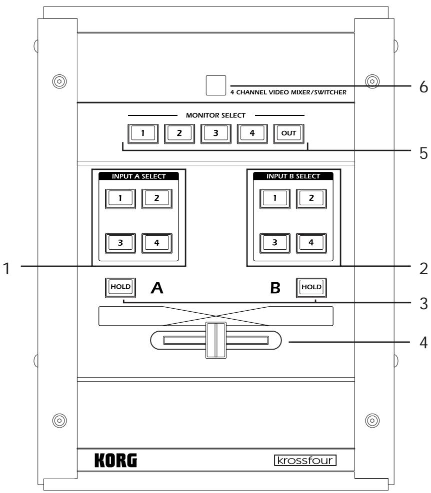
1. INPUT A SELECT keys
These keys select the input source for Channel A.
When you press a key, it will light up solid to indicate that the source is selected.
If the MODE switch is set to C-K (Chroma-key) or L-K (Luma-key), the selected source will be used as the background image for a compositing effect.
Press the same key a second time and it will begin blinking. When the key is blinking, the input source will be ignored, and the output of the channel will depend on the MODE setting. If the MODE switch is set to BK (Black) or WH (White), the blinking key indicates that the unit is ignoring the source image and outputting the specified background color instead. These solid backgrounds can then be used as a source for video mixing.
If the MODE switch is set to C-K (Chroma-key) or L-K (Luma-key), the blinking key indicates that the input source will be ignored and a black background will be used for the compositing effect.
Note: If there is no device connected to the selected input (or there is no signal from the connected unit), the krossfour will output a blue background screen.
2. INPUT B SELECT keys
These keys select the input source for Channel B.
When you press a key, it will light up solid to indicate that the source is selected.
If the MODE switch is set to C-K (Chroma-key) or L-K (Luma-key), the selected source will be used as the foreground image for a compositing effect.
Press the same key a second time and it will begin blinking. When the key is blinking, the input source will be ignored, and the output of the channel will depend on the MODE setting. If the MODE switch is set to BK (Black) or WH (White), the blinking key indicates that the unit is ignoring the source image and outputting the specified background color instead. These solid backgrounds can then be used as a source for video mixing.
If the MODE switch is set to C-K (Chroma-key) or L-K (Luma-key), the blinking key indicates that the input selected for Channel B will be ignored and only Channel A will be output. In the C-K Mode, however, if the HOLD key is pressed while any INPUT B SELECT key is blinking, a black screen will be output for Channel B instead.
Note: If there is no device connected to the selected input (or there is no signal from the connected unit), the krossfour will output a blue background screen.
3. HOLD keys
There are two HOLD keys; one for each channel. Pressing the HOLD key freezes the image from the selected source (on that channel), so that the image appears as a still. The key acts as a toggle: press it once to freeze the image, and again to return to a moving image.
Note that you can change the input source while the image is frozen, but the frozen image will continue to be output until the HOLD key is released.
In the C-K mode, the Channel B HOLD key has a special function. When any of the INPUT B SELECT keys are blinking, pressing the Channel B HOLD key will cause Channel B to output a full black screen.
4. Fader
Dynamically adjusts the mix between Channel A and Channel B. If the MODE switch is set to C-K or L-K, the fader operates only on the foreground or overlay (Channel B) portions of the image.
5. MONITOR SELECT keys
The MONITOR feature allows you to view any input source before it is assigned to a mixer channel. This provides you with the ability to preview, audition or "cue-up" a video source. Use the MONITOR SELECT keys to select which of the four inputs will be sent to the MONITOR OUT jack on the front panel. If you select OUT, the MONITOR OUT provides the same (mixed) signal as the VIDEO OUTPUT jack.
6. Power Indicator
Lights up to indicate that the power is on.
Note: If this lamp starts blinking, please turn off the power immediately.
Front Panel
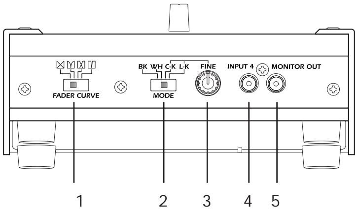
1. FADER CURVE switch
This switch selects the fader curve. The curve determines how the fader affects the mixing of the two channels. If the MODE switch is set to C-K or L-K, the fader only affects Channel B.
(Normal curve): Sliding the fader causes a gradual, linear change in the mix between the two channels. The center position corresponds to a 50:50 mix. This is a typical crossfade operation; movement in either direction attenuates one channel while amplifying the other.
(No mix): Sliding toward the center attenuates both channels; sliding to either end amplifies the corresponding channel. The two channels never mix.
(Center mix): Channels are mixed only over the central span of the fader range,
(Switcher): The fader acts like a toggle switch that selects either Channel A or Channel B.
There is no attenuation and no mixing.
2. MODE switch
Selects the background color or the overlay mode.
BK (Black): Sets the background color to black.
WH (White): Sets the background color to white.
C-K (Chroma key): The unit cuts out the blue parts of the (foreground) Channel B image, so that the Channel A signal (background) shows through the cutouts.
L-K (Luminance key): The unit cuts out the black and white portions from the (foreground) Channel B signal, so that the Channel A image (background) shows through the cutouts.
Note: For C-K and L-K modes, Channel A serves as the background and Channel B is the overlay. Note that when signals are being mixed in these ways, the fader affects only the Channel B image.
3. FINE knob (C-K/L-K Level Adjustment)
This control is effective only in C-K and L-K modes. If the mode is set to C-K, this knob will adjust the color of the area that will be "keyed-out" or removed from the foreground image (Channel B). If the mode is set to L-K, this knob will adjust the brightness level (from white to gray to black) of the area that will be "keyed-out" or removed from the foreground image (Channel B).
4. INPUT 4jack
This input accepts a composite video signal.
5. MONITOR OUT jack
The signal provided by this output is selected by using the MONITOR SELECT keys.
Rear Panel
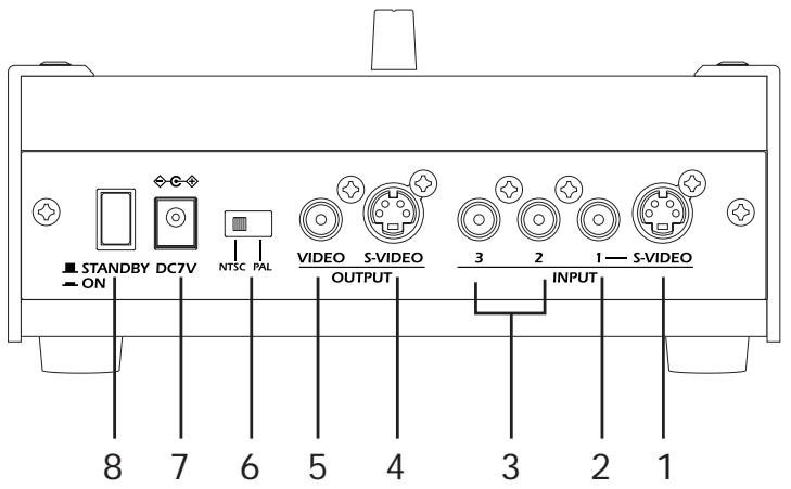
1. INPUT 1 S-VIDEO connector
This input accepts an S-VIDEO connector.
2. INPUT 1 jack
This input accepts a composite video signal.
If you connect both the S-VIDEO connector and the INPUT 1 jack, only the S-VIDEO input will be effective.
3. INPUT 2 jack, INPUT 3 jack
These inputs accept composite video signals.
4. OUTPUT S-VIDEO connector
This output provides the output from the krossfour's mixer as an S-VIDEO signal. Specifically, this signal will be the signals from Channel A and Channel B (as selected by the INPUT SELECT keys), after they have been mixed and processed by the fader.
5. OUTPUT jack
This output provides the output from the krossfour's mixer as a composite video signal
Note: The OUTPUTS-VIDEO connector and the OUTPUT jack both provide the same content. Both outputs can be used at the same time.
6. NTSC/PAL switch
This switch is used to select the video standard you are using. Turn the krossfour off to change the setting on this switch. The krossfour reads the setting of this switch when power is first turned on, and the setting cannot be changed until you turn the power off.
NTSC: Japan, North America, etc.
PAL: Europe, etc.
Note: Be sure this switch is set to match the standard of your input signals, or the output signal will be garbled.
7. DC 7V IN
Connect the AC adaptor (included) to this jack.
8. Power switch
Switches the power between ON and STANDBY.
Operating Procedure
1. Make the connections.
Connect the OUTPUT jack, the OUTPUT S-VIDEO connector, and/or the MONITOR OUT jack of the krossfour to the input of the display device(s) - monitor, projector, etc.
Connect the output of the source devices (DVD players, cameras, PCs, etc.) to the INPUT jacks of the krossfour.
Connect the AC adapter (included) to the DC 7V IN connector, and plug the other end into a power outlet.
2. Turn on the power.
Turn the power switch ON.
3. Select and control the image output.
Use the INPUT SELECT keys to select an input source for each channel.
Slide the fader to the A side to output the source signal selected by the INPUT A SELECT keys. Slide the fader to the B side to output the source signal selected by the INPUT B SELECT keys.
Select a different FADER CURVE setting to change the fader's operating characteristics.
4. Output a still image.
Press the HOLD key for either channel to freeze the channel's input signal and output this frozen image as a still. Press the HOLD key a second time to return to normal output.
5. Output the selected background color from either channel.
Either channel can be set to output a black screen image or a white screen image. Choose which Channel will output the background color, and press the currently lit INPUT SELECT key for that channel. The key will start to blink, and the input signal will be replaced by the background color selected by the MODE switch, either black (if the MODE switch is set to BK) or white (if WH).
6. Creating Composite Images
Composite images (or "compositing effects") are special effects that combine two video sources into one image - placing a toy dinosaur in downtown Chicago, for example. Generally, one image is set as the background plate, and portions of the second image appear in the foreground as an overlay.
There are two different ways to specify which portions of the foreground image will be keyed-out, allowing the background image to show through. Chroma-key effects remove areas of the foreground based on their color. Traditionally, the blue portions are removed, so a subject standing in front of a "blue screen" can be superimposed on any background. Luma-key effects rely on removing the black, white or specific gray portions of the image based on their brilliance, rather than color.
When using the krossfour in the Chroma-key (CK) or Luma-key (LK) modes, Channel A will be used as the background plate, and Channel B will be used as the overlay, or foreground image. Here's how. Select the source for the background image by pressing the appropriate INPUT A SELECT key. Select the source for the overlay (foreground) image by pressing the appropriate INPUT B SELECT key.
Use the MODE switch to select the type of compositing effect; either C-K (Chroma-key) or L-K (Luminance-key). If you have selected C-K, the blue parts of the foreground image (Chan
nel B) will be removed. If you have selected L-K, the black or white portions of the foreground image (Channel B) will be removed. In each case, the Channel A image will be visible through the areas that have been removed by the "key" effect.
You can adjust the extent of the cut-out area by using the FINE dial. Sliding the fader to the B side will make it easier to adjust the FINE dial setting.
Specifications
Video Formats: NTSC/PAL ITU601
Video Sampling Rate: 13.5 MHz, 4:2:2, 8-bit
Frame Synchronizers: A and B (1 each)
Inputs: INPUT 1 (S-VIDEO/composite), INPUT 2, INPUT 3, INPUT 4
Outputs:VIDEO OUTPUT (S-VIDEO),VIDEO OUTPUT (composite), MONITOR OUTPUT
Switches: FADER CURVE (4 settings); MODE (Black background, White background, Chroma-key, Luminance-key); FINE dial (for Chroma-key and Luminance-key adjustment)
Composite Effects: Chroma-key, Luminance-key
Power: DC7V (dedicated AC adapter)
Dimensions: 185(W) _ 249(D) _ 75(H) mm [7.3 (W) _ 9.8 (D) _ 3.0 (H) in.]
Weight: 1.5kg [3.3 lb.]
Included Accessory: AC adapter
Appearance and specifications of this product are subject to change without notice.
Précautions
Emplacement
Dimensions: 185 (L) × 249 (P) × 75 (H) mm
Poids: 1,5kg
This product has been manufactured according to strict specifications and voltage requirements that are applicable in the country in which it is intended that this product should be used. If you have purchased this product via the internet, through mail order, and/or via a telephone sale, you must verify that this product is intended to be used in the country in which you reside.
WARNING: Use of this product in any country other than that for which it is intended could be dangerous and could invalidate the manufacturer's or distributor's warranty.
Please also retain your receipt as proof of purchase otherwise your product may be disqualified from the manufacturer's or distributor's warranty.
REMARQUE IMPORTANTE POUR LES CLIENTS
- Power supply
- Interference with other electrical devices
- Handling
- Care
- Keep this manual
- Keeping foreign matter out of your equipment
- THE FCC REGULATION WARNING (for U.S.A.)
- CE mark for European Harmonized Standards
- COPYRIGHT WARNING
- A note about using this video device
- Video Signal Standard
- Features
- Two-channel video mixer with four source inputs
- Backlit Crossfader
- Monitor Output
- Chroma-key or "Blue-Screen" effects
- Luma-key effects
- Internal Time Base Corrector (TBC)
- Switches and Connectors
- Top Panel
- INPUT A SELECT keys
- INPUT B SELECT keys
- HOLD keys
- Fader
- MONITOR SELECT keys
- Power Indicator
- Front Panel
- FADER CURVE switch
- MODE switch
- FINE knob (C-K/L-K Level Adjustment)
- INPUT 4jack
- MONITOR OUT jack
- Rear Panel
- INPUT 1 S-VIDEO connector
- INPUT 1 jack
- INPUT 2 jack, INPUT 3 jack
- OUTPUT S-VIDEO connector
- OUTPUT jack
- NTSC/PAL switch
- DC 7V IN
- Power switch
- Operating Procedure
- Make the connections.
- Turn on the power.
- Select and control the image output.
- Output a still image.
- Output the selected background color from either channel.
- Creating Composite Images
- Specifications
- Précautions
- Emplacement
- REMARQUE IMPORTANTE POUR LES CLIENTS
Brand : KORG
Model : KF4
Category : Synthesizer