
AKKU IP Tourlight 200 - Projector Eurolite - Free user manual and instructions
Find the device manual for free AKKU IP Tourlight 200 Eurolite in PDF.


| Product Type | LED Projector (Stage Lighting) |
| Model | AKKU IP Tourlight 200 |
| Brand | Eurolite |
| Light Source | 200W High-Power LED |
| Luminous Flux | Approx. 20,000 lm |
| Beam Angle | 15° - 60° (adjustable) |
| Color Temperature | 3,200 K - 6,500 K (variable) |
| Power Supply | Built-in rechargeable battery (Li-Ion, 24V) |
| Battery Capacity | 200 Wh (approx. 10 hours runtime at full output) |
| Charging Time | 4 hours |
| IP Rating | IP65 (dust-tight and protected against water jets) |
| Control | DMX-512, Master/Slave, Standalone |
| DMX Channels | 3 / 5 / 10 channels (selectable) |
| Dimensions (L x W x H) | 320 x 220 x 220 mm |
| Weight | 5.2 kg |
| Housing Material | Aluminum die-cast, black finish |
| Mounting | Omega bracket with locking screw (included) |
| Accessories Included | Power cord, DMX cable, user manual |
| Spare Parts Available | LED module, battery pack, power supply, DMX board |
| Repairability | Modular design; replaceable components |
| Cleaning Instructions | Use a dry, soft cloth. Do not use solvents or abrasive cleaners. |
| Safety Features | Overheat protection, overcurrent protection, IP rated enclosure |
| Operating Temperature | -20°C to +45°C |
| EMC Compliance | CE, RoHS |
Frequently Asked Questions - AKKU IP Tourlight 200 Eurolite
User questions about AKKU IP Tourlight 200 Eurolite
0 question about this device. Answer the ones you know or ask your own.
Ask a new question about this device
Download the instructions for your Projector in PDF format for free! Find your manual AKKU IP Tourlight 200 - Eurolite and take your electronic device back in hand. On this page are published all the documents necessary for the use of your device. AKKU IP Tourlight 200 by Eurolite.
USER MANUAL AKKU IP Tourlight 200 Eurolite
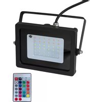
AKKU IP Tourlight 200
RGB+WW Spot

Silent IP65 spotlight with RGB+WW color mixture, QuickDMX, CRI >90battery powered

BATTERY POWERED

DMX
STAND ALONE
MASTER SLAVE

REMOTE CONTROL
STROBE
RGB+WW
COB
IP65
FLICKER FREE
30°
<70 CRI 70-80 CRI 80-90 CRI 90+ CRI COLOR RENDERING INDEX
QuickDMX
No. 41700900
www.eurolite.de
Inhaltsverzeichnis
Deutsch
EINFÜHRUNG 4
Produktmerkmale 4
SAFETY INSTRUCTIONS....23
DESCRIPTION OF THE DEVICE 25
INSTALLATION 26
DMX CONNECTION 27
Wireless via QuickDM- 28
Transmission modes....28
POWER SUPPLY 29
Charging the battery pack....29
Battery status....29
OPERATION 30
Operating buttons 30
Menu structure 30
Stand-alone mode 31
Cabled master/slave operation.... 32
Remote control IR-7 33
DM- operation 34
CLEANING AND MAINTENANCE 37
PROTECTING THE ENVIRONMENT 37
TECHNICAL SPECIFICATIONS.... 38
Accessories 39
You can find the latest update of this user manual in the Internet under:
www.eurolite.de
BEDIENUNGSANLEITUNG
eurolite®
AKKU IP TOURLIGHT 200 RGB+WW
NETZANSCHLUSS
DANGER! Electric shock caused by short-circuit
Be careful with your operations. With a dangerous voltage you can suffer a dangerous electric shock when touching the wires. Never open the housing.

read these instructions carefully before using the product. They contain important information for the correct use of the product.
Every person involved with the installation, operation and maintenance of this device has to
- be qualified
- follow the instructions of this manual
- consider this manual to be part of the total product
- keep this manual for the entire service life of the product
- pass this manual on to every further owner or user of the product
- download the latest version of the user manual from the Internet
INTRODUCTION
Thank you for having chosen one of our products. If you follow the instructions given in this manual, we are sure that you will enjoy this device for a long period of time.
Product features
Silent IP65 battery powered spotlight with RGB+WW color mixture, QuickDMX, CRI >90
• High-performance LED spot for outdoor applications
- Chip-on-board technology makes for superior color mixing
- For indoor and outdoor use (IP65)
- Battery operation up to 20 hours (depending on program used), recharging time 4.5 hours
- Beam angle 30°
• 1 high-power 200 W RGB+WW COB LED (4in1)
- Stand-alone, master/slave and DM– mode
- Integrated QuickDM– transceiver for wireless DM– control
• 9 built-in show programs in auto mode
- Direct color selection for 27 preset colors
• Variable color temperature 1800-8000 K
• Electronic dimmer (0-100%)
• Strobe effect 0-20 Hz
• Control panel with LC display for easy configuration
- Convenient wireless control via included IR remote control
- Swivel mounting bracket
• Additional bracket for floor use
- Mains input and output for power linking up to 8 units
- Incl. quick-lock Omega holder
- Optional barndoors
SAFETY INSTRUCTIONS
WARNING!
Please read the safety warnings carefully and only use the product as described in this manual to avoid accidental injury or damage.
Intended use
- This product is designed to light indoor and outdoor areas and is IP65 rated. It can be mounted and operated in indoor and outdoor areas. This device is designed for professional use in the field of event technology, e.g. on stage. It is not suitable for household lighting.
- The integrated QuickDM– receiver for wireless reception of DM–512 signals operates in the 2.4 GHz ISM range and is license-free and generally approved for operation in EU and EFTA countries.
- Only use the device according to the instructions given herein. Damages due to failure to follow these operating instructions will void the warranty! We do not assume any liability for any resulting damage.
- We do not assume any liability for material and personal damage caused by improper use or non-compliance with the safety instructions. In such cases, the warranty will be null and void.
- Unauthorized rebuilds or modifications of the device are not permitted for reasons of safety and render the warranty invalid.
Danger due to electricity
- To reduce the risk of electric shock, do not open any part of the device. There are no serviceable parts inside the device.
- Do not immerse the product in water, this will destroy it. Furthermore, this could cause a lethal electric shock!
- The protective cap located on the power input must be kept closed when using the product outdoors.
- Only connect the device to a properly installed mains outlet. The outlet must be protected by residual current breaker (RCD). The voltage and frequency must be exactly the same as stated on the device. If the mains cable is equipped with an earthing contact, then it must be connected to an outlet with a protective ground. Never deactivate the protective ground of a mains cable. Failure to do so could possibly injure the user.
- The mains outlet must be easily accessible so that you can unplug the device quickly if need be.
- Never touch the mains plug with wet or damp hands. There is the risk of potentially fatal electric shock.
- The mains cable must not be bent or squeezed. Keep it away from hot surfaces or sharp edges.
- Never pull the mains cable to disconnect the mains plug from the mains outlet, always seize the plug.
- Unplug the device during lighting storms, when unused for long periods of time or before cleaning.
- Do not expose the device to any high temperatures, direct sunlight, strong vibrations or heavy mechanical stress. Do not operate the device in tropical climate.
- Only have repairs to the device or its mains cable carried out by qualified service personnel. Repairs are required when the device or the mains cable is visibly damaged, when the device has been dropped or malfunctions occur.
Danger to children and people with restricted abilities
- This product is not a toy. Keep it out of the reach of children and pets. Do not leave packaging material lying around carelessly. Never leave this device running unattended.
- This device may be used only by persons with sufficient physical, sensorial, and intellectual abilities and having corresponding knowledge and experience. Other persons may use this device only if they are supervised or instructed by a person who is responsible for their safety.
English
Warning – risk of burns and fire
- The admissible ambient temperature range (Ta) is -5 to +45°C. Do not operate the device outside of this temperature range.
- The housing temperature (Tc) can be up to 60°C during use. Avoid contact by persons and materials.
- Do not illuminate surfaces within 20 cm of the device. This value is indicated on the device by the symbol.
· ∩---m - Do not use the device near highly flammable materials. Always place the device at a location where sufficient air circulation is ensured. Leave 50 cm of free space around the device.
Warning – risk of injuries
- Do not look directly at the light source. Persons with light-sensitive epilepsy may suffer from epileptic seizures or fall unconscious.
- Make sure that the product is set up or installed safely and expertly and prevented from falling down. Comply with the standards and rules that apply in your country, in particular EN 60598-2-17.
- The manufacturer cannot be made liable for damages caused by incorrect installations or insufficient safety precautions.
- For commercial use the country-specific accident prevention regulations of the government safety organization for electrical facilities must be complied with at all times.
Caution – material damage
- This device may not be connected to the mains voltage by means of a dimmer.
- Lighting effects are not designed for permanent operation. Consistent operation breaks will ensure that the device will serve you for a long time without defects.
- Never switch the device on and off in short intervals. This will considerably reduce the service life of the device.
- If the device has been exposed to drastic temperature fluctuation, do not switch it on immediately. The resulting condensation may destroy the device. Allow the device to reach room temperature before connecting it. Wait until the condensation has evaporated.
- This device is constructed for a standing installation only and may only be installed on a solid, plane, skidproof, vibration-free, oscillation-free and non-flammable surface. This device may never be suspended.
- Please use the original packaging to protect the device against vibration, dust and moisture during transportation or storage.
- If a serial number label is affixed to the device, do not remove the label as this would make the warranty void.
Recharable batteries/batteries
- The given battery operating time depends largely on the operating mode and ambient temperature. Low temperatures will reduce the operating time considerably. Before using the device for the first time, completely charge the battery.
- The contained lithium-ion battery is subject to the Dangerous Goods Legislation requirements. When being transported, special requirements on packaging and labelling must be observed. When preparing the item for shipping, consultation of an expert for hazardous material or a forwarding agency is required. Please also observe possibly more detailed national and international regulations.
- Make sure that the poles are correct when inserting the remote control batteries. Never let batteries lie around openly as there is the danger that these can be swallowed by children or domestic animals. Immediately consult a doctor when batteries are swallowed! Leaking or damaged batteries can cause irritations when getting into contact with the skin. In this case use appropriate protective gloves. Make sure that the batteries cannot be short-circuited, thrown into the fire and be charged. There is a danger of explosion.
DESCRIPTION OF THE DEVICE

(1) Stand/mounting bracket
(2) 200 W RGB+WW COB LED (4in1)
(3) Infrared sensor for the remote control
(4) Fixation screw
(5) DM- input
(6) Antenna for QuickDM—
(7) LC display with operating buttons

(8) ON/OFF switch
(9) DM- output
(10) Pressure compensation plug
(11) Power in
(12) Safety eyelet
(13) Power out
Note: When connected correctly, the power and DM- sockets are protected from spraying water according to IP65. When not in use, make absolutely sure to close the sockets with the rubber sealing caps.
INSTALLATION
WARNING! Risk of injury caused by falling objects
Devices in overhead installations may cause severe injuries when crashing down. Make sure that the device is installed securely and cannot fall down. The installation must be carried out by a specialist who is familiar with the hazards and the relevant regulations.
The device may be placed on the floor by unfolding the brackets or fastened to a truss or similar rigging structure. The device must never be fixed swinging freely in the room.
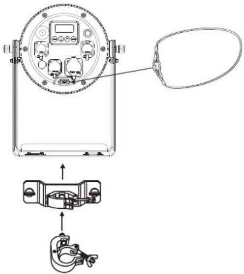
1 The rigging structure must support at least 10 times the weight of all fixtures to be installed on it.
2 Block access below the work area and work from a stable platform when installing the device.
3 Use rigging hardware that is compatible with the structure and capable of bearing the weight of the device. Please refer to the "Accessories" section for a list of suitable rigging hardware.
![graph TD A["Step 1"] --> B["Step 2"] B --> C["Step 3"] C --> D["Step 4"] D --> E["Step 5"] E --> F["End"]](/content/2026/07/1435904/images/3e052d8493d54c853e33ca4b35cfd9eefaa7faa4803ac71010eaa9df54aeda2e.jpg)
(1) Coupler
(2) Quick-lock fastener
(3) Omega bracket
Screw one coupler via an M10 screw and self-locking nut onto the Omega bracket. Insert the quick-lock fasteners of the Omega bracket into the respective holes on the mounting plate of the mounting bracket. Tighten the quick-lock fasteners fully clockwise.
4 Secure the device with a safety bond or other secondary attachment. This secondary safety attachment must be sufficiently dimensioned in accordance with the latest industrial safety regulations and constructed in a way that no part of the installation can fall down if the main attachment fails. An appropriate eyelet is installed on the device for fixation of the safety bond. Fasten the safety bond in such a way that, in the event of a fall, the maximum drop distance of the device will not exceed 20 cm.
5 To align the device, release the fixation screws at the mounting bracket, adjust the desired inclination angle and tighten the fixation screws.
6 After installation, the device requires inspections periodically to prevent the possibility of rot, deformation and looseness.
English
DMX CONNECTION
![graph LR A["DMX Controller"] --> B["Device 1 Start Address 1"] B --> C["Device 2 Start Address 11"] C --> D["Device 3 Start Address 21"]](/content/2026/07/1435904/images/f917ce1e0748e0bdf0c973672c0e1b9c66867e7bd3eb4d7d872d82323c3ce774.jpg)
A DM-512 data link is required in order to control the device via DM-. The device provides special DM-connectors, which are designed according to protection class IP65. Matching DM- connection cables with special plugs are optionally available. When not in use, make absolutely sure to close the connections with the rubber sealing caps to prevent moisture and dirt from penetrating.
1 Connect the output of your DM- controller to the DM- input DM- IN of the device with a DM- cable.
2 Connect the DM- output DM- OUT of the device to the DM- input of the next unit in the chain. Always connect one output to the input of the next unit until all units are connected.
3 At the last unit, the DM– cable has to be terminated. Plug the terminator with a 120 Ω resistor between Signal (−) and Signal (+) in the DM– output of the last unit.
4 If the cable length exceeds 300 m or the number of DM– devices is greater than 32, it is recommended to insert a DM– level amplifier to ensure proper data transmission.
-LR connection:
DMX-output
XLR mounting-socket:

DMX-input
XLR mounting-plug:

English
Wireless via QuickDMX
Connect the QuickDM– transmitter to the DM– controller. Put the transmitter and the AKKU IP Tourlight into operation and set them to the same transmission channel. Use menu option SET 2.4G on the spotlight to do this. Thus, the wireless DM– network is set up and the spotlight is paired to the QuickDM– transmitter. The assignment of the spotlight to the transmitter is kept memorized even after disconnecting the power supply.
Transmission modes
QuickDM— allows creating reliable point-to-point, point-to-multipoint and even multipoint-to-multipoint installations over large distances and in any environment (please refer to the controller's documentation). A single QuickDM— transmitter transmits all 512 DM— channels to a maximum of 512 spotlights. It is possible to operate 6 transmitters at the same time in order to control a total of 3072 DM— channels. The maximum range is 400 m.
Point-to-point connection:

Point-to-multipoint connection:

POWER SUPPLY
The device can be operated with mains voltage and for mobile use via the internal rechargeable battery.

The device uses an auto-range power supply that accepts input voltages between 100 und 240 volts. The power connectors are designed according to protection class IP65. Matching connection cables with special plugs are optionally available. When not in use, make absolutely sure to close the connections with the rubber sealing caps to prevent moisture and dirt from penetrating.
1 Connect the device via the mains cable to a grounded mains socket.
2 Press the power button.
3 Do not connect the unit to the mains voltage via a dimmer.
4 The jack POWER OUT allows for power supply of further devices. To interconnect several devices, connect the jack POWER OUT to the input POWER IN of the next unit until all units are connected. In this manner, up to 8 devices can be linked at 230/240 input voltage and up to 4 devices at 110/115 input voltage.
Charging the battery pack
Prior to operating the device off mains for the first time, the rechargeable battery must be fully charged. You can charge the product using the power cable.
1 Switch on the device with the power button. The operating time of the battery depends on the operating mode and the ambient temperature (max. 20 hours). After the operation, switch the device off.
2 For charging the battery, connect the device to a power outlet via the power cable provided. Charging time is 4.5 hours. The device may be operated during the charging procedure.
3 The device features a protective circuit for charging which prevents overload of the rechargeable battery. However, disconnect the device from the mains after charging.
4 The device will heat up during charging; this is normal.
5 To prevent damage to the battery by deep discharge, recharge a completely discharged battery as soon as possible. Do not store the unit with the battery completely discharged and regularly recharge the battery in case of long storage.
| Maximum battery run time Recharge time | |
| 20 hours 4.5 hours | |
Battery status
The battery charge level is shown in the display. The display shows the charge level of the battery in percent. If the charge level is low, the battery is soon exhausted and must be charged. The device can continue to be operated in this state for several minutes. Afterwards, a protection circuit against deep discharge switches the device off automatically.
OPERATION
Turn on the device via the power switch. The display indicates the last operating mode. The operating modes can be selected by means of the display and the control buttons. All settings remain stored even if the device is disconnected from the mains. The device can be operated in stand-alone mode via the control board and the EUROLITE IR-7 remote control or in DM-controlled mode via any commercial DM-controller and QuickDM-with suitable wireless transmitter.
Operating buttons
| Button Function | |
| MENU | Selects the operating mode or returns to the initial screen. |
| ENTER | Activates a value to be modified or saves a value when modifying. |
| UP | Selects the next menu item or increases values when modifying. |
| DOWN | Selects the previous menu item or decreases values when modifying. |
Menu structure
| Mode | Display | Function | |
| DMX mode | DM- | 10CH ADDR:001-512 | 10-channel mode and start address |
| 6CH ADDR:001-512 | 6-channel mode and start address | ||
| 5CH ADDR:001-512 | 5-channel mode and start address | ||
| 4CH ADDR:001-512 | 4-channel mode and start address | ||
| 3CH ADDR:001-512 | 3-channel mode and start address | ||
| Preset colors | STATIC S 01-27 | Constant lighting in one of 27 colors | |
| Automatic mode | AUTO 01-09 | Auto programs 01-09 | |
| Running speed in automatic mode | SPEED 01-09 | Program running speed slow > fast | |
| Color mix | COLOR | R000-255 Red 0-100% | |
| G000-255 Green 0-100% | |||
| B000-255 | Blue 0-100% | ||
| W000-255 | Warm white 0-100% | ||
| Color temperature | TEMPERAT | 1800K | 1800K |
| 2200K | 2200K | ||
| 2700K | 2700K | ||
| 3200K | 3200K | ||
| 4300K | 4300K | ||
| 5600K | 5600K | ||
| 6500K | 6500K | ||
| 8000K | 8000K | ||
| Dimmer | DIMMING | 01-99 | Total brightness dark > bright |
| Color fade in and out | FADING | 00-99 | Fading program slow > fast |
| Strobe effect | FLASH | 00-99 | Strobe effect slow > fast |
| Behavior in case of missing DMX signal | DM-lost | Blackout | LEDs switched off |
| Hold | Most recent DM-value is held | ||
| Full | All LEDs light at 100% brightness | ||
| Static | Last selected static color (01-27) | ||
| Auto | Last selected auto program (01-09) | ||
| Slave mode | SLAVE | SLAVE MODE | Slave mode |
English
| Battery mode | BATTERY | Super Super bright mode | |
| Normal Normal mode | |||
| Economy Energy-saving mode | |||
| Key lock | PASSCODE | ON Key lock on | |
| OFF Key lock off | |||
| Wireless 2.4 G | SET 2.4 G ON/OFF | Red | Transmission channel wireless DM- |
| Green | |||
| Blue | |||
| R+G | |||
| G+B | |||
| R+B | |||
| IR remote control | INFRARED | ON IR remote control on | |
| OFF IR remote control off | |||
| Firmware version | Vx.x Vx.x Firmware version number | ||
Stand-alone mode
Preset colors
In the STATIC mode the device will constantly emit one of 27 preset colors.
1 Press the MENU button so many times until STATIC is indicated in the display. Confirm with the ENTER button.
2 Use the buttons UP and DOWN to adjust the desired color. Confirm with the ENTER button.
Automatic mode
In automatic mode, 9 programs are available that run at an adjustable speed.
1 Press the MENU button so many times until AUTO is indicated in the display. Confirm with the ENTER button. Use the buttons UP and DOWN to select the desired program (01-09). Confirm with the ENTER button.
2 Press the MENU button so many times until SPEED is indicated in the display. Confirm with the ENTER button. Use the buttons UP and DOWN to adjust the running speed of the program from 01 (slow) to 09 (fast). Confirm with the ENTER button.
Individual color mix
In the color mode COLOR each of the quadcolor LEDs can be individually adjusted for brightness. The device will constantly emit the color adjusted.
1 Press the MENU so many times until COLOR is indicated in the display. Confirm with the ENTER button.
2 Now the display indicates the letter R for the color and the corresponding brightness value. Use the buttons UP and DOWN to adjust the desired brightness.
3 Confirm with the ENTER button. Now the color green can be adjusted; then blue and white.
Color temperature
In TEMPERAT mode the device will constantly emit white light. The color temperature of the light beam is adjustable.
1 Press the MENU button so many times until TEMPERAT is indicated in the display. Confirm with the ENTER button.
2 Use the buttons UP and DOWN to select the desired color temperature (1800K- 8000K). Confirm with the ENTER button.
English
Total brightness
Menu DIMMING allows adjusting the total brightness for all stand-alone operating modes.
1 Press the MENU button so many times until DIMMING is indicated in the display. Confirm with the ENTER button.
2 Use the buttons UP and DOWN to adjust the desired brightness (01 = dark, 99 = bright). Confirm with the ENTER button.
Color fade in and out
FADING mode enables color fade in and out. The speed is adjustable.
1 Press the MENU button so many times until FADING is indicated in the display. Confirm with the ENTER button.
2 Use the buttons UP and DOWN to adjust the desired speed (00-99). Confirm with the ENTER button.
Strobe effect
FLASH mode enables strobe effects. The flash frequency is adjustable.
1 Press the MENU button so many times until FLASH is indicated in the display Confirm with the ENTER button.
2 Use the buttons UP and DOWN to adjust the desired speed (00-99). Confirm with the ENTER button.
Behavior at missing DMX-signal
In DMX lost mode the program offers different options when no DM– signal is received.
1 Press the MENU button repeatedly until the display shows the DMX lost menu. Press ENTER to confirm.
2 Select the desired program with the UP and DOWN buttons (see menu structure). Confirm with ENTER.
Cabled master/slave operation
Several devices may be interconnected (max. 32) via DM–cables. Then all slave units can be synchronized and controlled with the master unit without the need for a DM–controller. The devices must be set to the corresponding operating modes.
1 Configure all slave units before connecting the master unit: Press the MENU button so many times until SLAVE is indicated on the display. Confirm with the ENTER button.
2 Connect the DM– output of the master unit to the DM– input of the first slave unit. Then connect the DM– output of the first slave unit to the DM– input of the second slave unit, etc. until all units have been connected in a chain. Make sure the master unit is the first in the chain. Do not connect a DM– controller to the DM– input of the master unit.
3 Set the master unit to a stand-alone mode (STATIC, AUTO, COLOR, etc.). The interconnected devices will now operate in sync.
Master/slave operation via QuickDMX
1 Set the master device and each slave device to the same transmission channel using the function SET 2.4G. Thus, the spotlights are paired.
2 Set the master unit to the desired operating mode and all slave units to SLAVE mode. The devices will now operate in sync.
Key lock
You can lock the operating buttons to e.g. prevent menu tampering. If the menu option PASSCODE is enabled, the buttons will be automatically locked from the last command. In order to disable the key lock function, press these buttons in the following order: UP, DOWN, UP, DOWN, ENTER.
QuickDMX transmission channel/Wireless 2.4G
You can use the SET 2.4G menu to set the wireless transmission channel for QuickDM– operation. Use the buttons UP and DOWN to choose wireless transmission channel with ON (QuickDM– enabled) or OFF (QuickDM– disabled). Confirm with the ENTER button. Please refer to the corresponding chapter for further explanation.
English
Remote control IR-7
The device must be activated for remote control. For this, set menu item INFRARED to ON. When actuating a button, always direct the remote control towards the sensor. There must be no obstacles between remote control and the sensor. In DMX and slave mode, the remote control functions are deactivated.

| Button Function | |
| BLACKOUT | LEDs off |
| AUTO | Automatic modeprogram selection with (+)/(-) |
| STROBE | Strobe effect for automatic modeflash rate setting with (+)/(-) |
| SPEED | Running speed in automatic modesetting with (+)/(-) |
| SENSITIVITY | Microphone sensitivitysetting with (+)/(-) |
| DMX | DMX mode on/off |
| MANUAL | Color modeselect colors with R/G/B/W, setting with (+)/(-) |
| FADE | Color fade in and out:speed setting with (+)/(-) |
| 1-9 | Total brightness(1 = dark, 9 = bright) |
Notes:
- The remote control is supplied with a battery inserted. An insulating foil between the battery and the battery contacts prevents the battery from being discharged during storage. Prior to the first operation remove the foil from the battery support on the rear side of the remote control. Otherwise operation of the remote control is not possible.
- If the range of the remote control decreases, replace the battery. For this purpose,
on the rear side of the remote control press the small bar with the groove to the right and at the same time remove the battery support. For operation, one 3 V button cell type CR 2025 is required. When inserting, pay attention that the positive pole of the button cell shows upwards in the support.

- Remove the battery from the remote control as a precaution if the device is not used for a longer period of time.
DMX operation
Setting the number of DMX channels and the DMX starting address
For operation with a controller with DM-512 protocol, the device is equipped with 10 control channels. However, it can also be switched to a mode with 3, 4, 5 or 6 channels if different functions are required. To be able to operate the device with a DM- controller, the DM- starting address must be set. The starting address depends upon which DM- controller is being used. Please refer to the controller's documentation.
1 Press the MENU button so many times until DMX is indicated in the display. Confirm with the ENTER button.
2 The display indicates 3 CH (3 DM– channels), 4 CH (4 DM– channels), 5 CH (5 DM– channels), 6 CH (6 DM– channels) or 10 CH (10 DM– channels). Use the buttons UP and DOWN to select the desired DM– channel mode. Confirm with the ENTER button.
3 Now the display indicates the menu item for the DM– start address ADDR***. Use the buttons UP and DOWN to set the address. Confirm with the ENTER button.
4 When receiving DM– control signals, the display shows “DM–”. If no DM– control signals are available, the display shows “NO SIGNAL”.
Note: Please make sure that you do not have any overlapping channels in order to control each device correctly and independently from any other fixture on the DM–chain If several devices are addressed to the same address, they will work synchronically.
Functions in DMX mode
3-channel mode
| Channel Value Function | ||
| 1 | 000 – 255 | Red 0-100% |
| 2 | 000 – 255 | Green 0-100% |
| 3 | 000 – 255 | Blue 0-100% |
4-channel mode
| Channel Value Function | ||
| 1 | 000 – 255 | Red 0-100% |
| 2 | 000 – 255 | Green 0-100% |
| 3 | 000 – 255 | Blue 0-100% |
| 4 | 000 – 255 | Warm white 0-100% |
5-channel mode
| Channel Value Function | ||
| 1Master dimmer | 000 – 255 | Total brightness 0-100 % |
| 2Strobe effect | 000 – 009 | No function |
| 010 – 255 | Strobe effect 0-100% | |
| 3Preset colors | 000 – 009 | No function |
| 010 – 019 | Red | |
| 020 – 029 | Green | |
| 030 – 039 | Blue | |
| 040 – 049 | Warm white | |
| 050 – 059 | Yellow | |
| 060 – 069 | Magenta | |
| 070 – 079 | Cyan | |
English
| 080 – 089 | Dark orange | |
| 090 – 099 | Green yellow | |
| 100 – 109 | Salmon | |
| 110 – 119 | Turquoise | |
| 120 – 129 | Light green | |
| 130 – 139 | Orange | |
| 140 – 149 | Straw | |
| 150 – 159 | Lavender | |
| 160 – 169 | Light blue | |
| 170 – 179 | Dark blue | |
| 180 – 189 | Pink | |
| 190 – 255 | All on | |
| 4Auto programs | 000 – 009 | No function |
| 010 – 034 | Auto program 1 | |
| 035 – 059 | Auto program 2 | |
| 060 – 084 | Auto program 3 | |
| 085 – 109 | Auto program 4 | |
| 110 – 134 | Auto program 5 | |
| 135 – 159 | Auto program 6 | |
| 160 – 184 | Auto program 7 | |
| 185 – 209 | Auto program 8 | |
| 210 – 255 | Auto program 9 | |
| 5Auto program speed | 000 – 255 | Speed slow > fast |
6-channel mode
| Channel Value Function | ||
| 1 | 000 – 255 | Red 0-100% |
| 2 | 000 – 255 | Green 0-100% |
| 3 | 000 – 255 | Blue 0-100% |
| 4 | 000 – 255 | Warm white 0-100% |
| 5Master dimmer | 000 – 255 | Total brightness 0-100 % |
| 6Internal programs | 000 – 000 | No function |
| 001 – 005 | Automatic color change (7 colors) | |
| 006 – 010 | No function | |
| 011 – 255 | Strobe effect 0-100% | |
10-channel mode
| Channel Value Function | ||
| 1Master dimmer | 000 – 255 | Total brightness 0-100 % |
| 2Strobe effect | 000 – 009 | No function |
| 010 – 255 | Strobe effect 0-100% | |
| 3 | 000 – 255 | Red 0-100% |
| 4 | 000 – 255 | Green 0-100% |
English
| 5 | 000-255 | Blue 0-100% |
| 6 | 000-255 | Warm white 0-100% |
| 7 Preset colors | 000-009 | No function |
| 010-019 | Red | |
| 020-029 | Green | |
| 030-039 | Blue | |
| 040-049 | Warm white | |
| 050-059 | Yellow | |
| 060-069 | Magenta | |
| 070-079 | Cyan | |
| 080-089 | Dark orange | |
| 090-099 | Green yellow | |
| 100-109 | Salmon | |
| 110-119 | Turquoise | |
| 120-129 | Light green | |
| 130-139 | Orange | |
| 140-149 | Straw | |
| 150-159 | Lavender | |
| 160-169 | Light blue | |
| 170-179 | Dark blue | |
| 180-189 | Pink | |
| 190-255 | All on | |
| 8 Auto programs | 000-009 | No function |
| 010-034 | Auto program 1 | |
| 035-059 | Auto program 2 | |
| 060-084 | Auto program 3 | |
| 085-109 | Auto program 4 | |
| 110-134 | Auto program 5 | |
| 135-159 | Auto program 6 | |
| 160-184 | Auto program 7 | |
| 185-209 | Auto program 8 | |
| 210-255 | Auto program 9 | |
| 9 Auto program speed | 000-255 | Speed slow > fast |
| 10 Color temperature | 000-009 | No function |
| 010-039 | 1800K | |
| 040-069 | 2200K | |
| 070-099 | 2700K | |
| 100-129 | 3200K | |
| 130-159 | 4300K | |
| 160-189 | 5600K | |
| 190-219 | 6500K | |
| 220-255 | 8000K |
CLEANING AND MAINTENANCE
The outside of the device should be cleaned periodically to remove contaminants such as dust etc. The lenses, in particular, should be clean to ensure that light will be emitted at maximum brightness.
1 Disconnect the device from power and allow it to cool before cleaning.
2 Clean the surface with a soft lint-free and moistened cloth. Never use alcohol or solvents as these may damage the surface. Make sure that no liquids can enter the device.
3 The device must be dry before reapplying power.
There are no serviceable parts inside. Do not open the housing. Do not try to repair the device by yourself as this may result in damage. Maintenance and service operations are only to be carried out by authorized dealers. Should you need any spare parts, please use genuine parts. Should you have further questions, please contact your dealer.
PROTECTING THE ENVIRONMENT
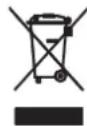
Disposal of old equipment
When to be definitively put out of operation, take the product to a local recycling plant for a disposal which is not harmful to the environment. Devices marked with this symbol must not be disposed of as household waste. Contact your retailer or local authorities for more information. Remove any inserted batteries and dispose of them separately from the product.

You as the end user are required by law (Battery Ordinance) to return all used batteries/rechargeable batteries. Disposing of them in the household waste is prohibited. You may return your used batteries free of charge to collection points in your municipality and anywhere where batteries/rechargeable batteries are sold. By disposing of used devices and batteries correctly, you contribute to the protection of the environment.
TECHNICAL SPECIFICATIONS
| Power supply: 100-240 V AC, 50/60 Hz | |
| IP classification: IP65 | |
| Protection class: Class I | |
| Power connection: | Mains input IP T-Con (M) power supply cord with safety plug (provided) |
| Power output: IP T-Con (F) mounting version | |
| Battery pack type: 1 x lithium ion 22,2 V, 4400 mAh, 97,68 Wh | |
| Battery pack: | Battery operation up to 20h depending on program used |
| Recharging time 4,5h | |
| Lamp type: LED lamp | |
| LED: | 1 x COB (chip-on-board) 200 W 4in1 QCL RGB+WW (homogenous color mix) |
| Color temperature: 1800K - 8000K adjustable | |
| Flash rate: 0 - 20 Hz | |
| DM- channels: 3; 4; 5; 6; 10 | |
| DM- input: 3-pin -LR (M) mounting version IP | |
| DM- output: 3-pin -LR (F) mounting version IP | |
| Cooling: Passive convection | |
| Control: | Stand-alone; DM-; QuickDM- built-in; IR remote control; Master/slave function; Light Captain; |
| Beam angle (1/2 peak): | 30° |
| Beam angle (1/10 peak): | 60° |
| Color rendering index (CRI) more than: | 90 Ra |
| Housing color: | Black |
| Display type: | LCD display |
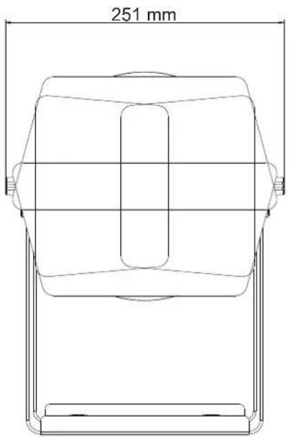
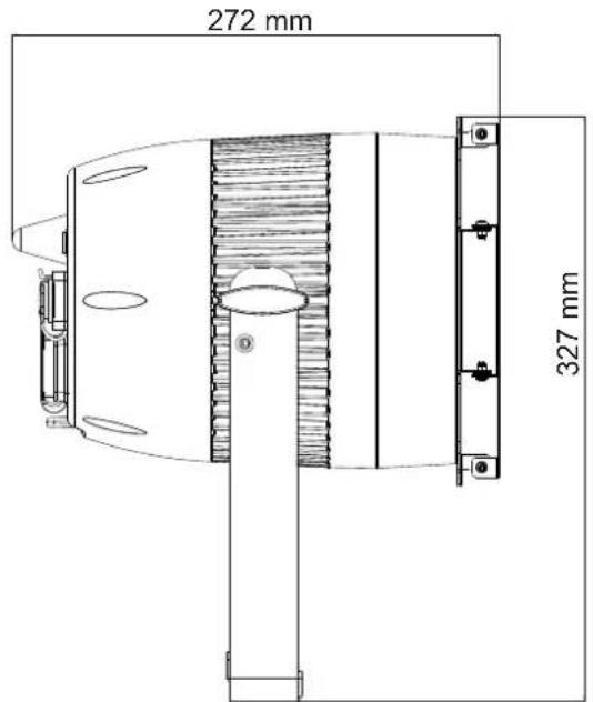
| Dimensions: | Width: 25,1 cm |
| Depth: 27,2 cm | |
| Height: 32,7 cm | |
| Diameter: ∅ 18,2 cm | |
| Weight: | 6 kg |
| Remote control | |
| Battery: | 1 x Button cell 3.0 V CR2025 lithium manganese |
All information is subject to change without prior notice. © 10.05.2022
Accessories
| EUROLITE Barndoors Theatre IP Tourlight No. 51914259 | |
| EUROLITE TPC-10 Coupler, silver No. 59006856 | |
| EUROLITE Safety Bond A 4x1000mm up to 15kg silver No. 58010320 | |
| PSSO DM– cable IP65 3pin 3m black No. 3022783C | |
| EUROLITE IP T-Con Power Cable 3x1.5 1,5m No. 30235005 | |
| EUROLITE QuickDM– Wireless Transmitter No. 70064700 | |
| EUROLITE Omega bracket 42 No. 51786558 | |
| EUROLITE IR-7 Remote Control No. 50530561 |


- AKKU IP TOURLIGHT 200
- INHALTSVERZEICHNIS
- DEUTSCH
- BEDIENUNGSANLEITUNG
- EUROLITE®
- AKKU IP TOURLIGHT 200 RGB+WW
- NETZANSCHLUSS
- DANGER! ELECTRIC SHOCK CAUSED BY SHORT-CIRCUIT
- INTRODUCTION
- PRODUCT FEATURES
- SAFETY INSTRUCTIONS
- WARNING
- INTENDED USE
- DANGER DUE TO ELECTRICITY
- DANGER TO CHILDREN AND PEOPLE WITH RESTRICTED ABILITIES
- ENGLISH
- WARNING – RISK OF BURNS AND FIRE
- WARNING – RISK OF INJURIES
- CAUTION – MATERIAL DAMAGE
- RECHARABLE BATTERIES/BATTERIES
- DESCRIPTION OF THE DEVICE
- INSTALLATION
- WARNING! RISK OF INJURY CAUSED BY FALLING OBJECTS
- DMX CONNECTION
- WIRELESS VIA QUICKDMX
- TRANSMISSION MODES
- POWER SUPPLY
- CHARGING THE BATTERY PACK
- BATTERY STATUS
- OPERATION
- STAND-ALONE MODE
- PRESET COLORS
- AUTOMATIC MODE
- INDIVIDUAL COLOR MIX
- COLOR TEMPERATURE
- TOTAL BRIGHTNESS
- COLOR FADE IN AND OUT
- STROBE EFFECT
- BEHAVIOR AT MISSING DMX-SIGNAL
- CABLED MASTER/SLAVE OPERATION
- MASTER/SLAVE OPERATION VIA QUICKDMX
- KEY LOCK
- QUICKDMX TRANSMISSION CHANNEL/WIRELESS 2.4G
- REMOTE CONTROL IR-7
- NOTES
- DMX OPERATION
- SETTING THE NUMBER OF DMX CHANNELS AND THE DMX STARTING ADDRESS
- FUNCTIONS IN DMX MODE
- 3-CHANNEL MODE
- 4-CHANNEL MODE
- 5-CHANNEL MODE
- CLEANING AND MAINTENANCE
- PROTECTING THE ENVIRONMENT
- DISPOSAL OF OLD EQUIPMENT
Brand : Eurolite
Model : AKKU IP Tourlight 200
Category : Projector