TB32CS - Electric mower MTD - Free user manual and instructions
Find the device manual for free TB32CS MTD in PDF.


User questions about TB32CS MTD
0 question about this device. Answer the ones you know or ask your own.
Ask a new question about this device
Download the instructions for your Electric mower in PDF format for free! Find your manual TB32CS - MTD and take your electronic device back in hand. On this page are published all the documents necessary for the use of your device. TB32CS by MTD.
USER MANUAL TB32CS MTD
Thank you for buying this quality product. This modern outdoor power tool will provide many hours of useful service. You will find it to be a great labor-saving device. This operator's manual provides you with easy-to-understand operating instructions. Read the whole manual and follow all the instructions to keep your new outdoor power tool in top operating condition.
PRODUCT REFERENCES, ILLUSTRATIONS AND SPECIFICATIONS
All information, illustrations, and specifications in this manual are based on the latest product information available at the time of printing. We reserve the right to make changes at any time without notice.
Copyright © 2004 MTD SOUTHWEST INC, All Rights Reserved.
SERVICE INFORMATION
Service on this unit both within and after the warranty period should be performed only by an authorized and approved service dealer.
For service call 1-800-520-5520 to obtain a list of authorized service dealers near you. For more details about your unit, visit our website at www.troybilt.com.
If you have difficulty assembling this product or have any questions regarding the controls, operation or maintenance of this unit, please call the Customer Support Department.
DO NOT RETURN THE UNIT TO THE RETAILER. PROOF OF PURCHASE WILL BE REQUIRED FOR WARRANTY SERVICE.
TABLE OF CONTENTS
Service Information 2
Rules for Safe Operation 3
Know Your Unit 6
Assembly Instructions 7
Operating Instructions 8
Maintenance and Repair Instructions 11
Troubleshooting Chart 14
Specifications 15
Warranty Information 16
Parts List . . . . . . . . . . . . . . . . . . . . . . . . . . . . . . . . . . . . . . . . . . . . . . . . . . . . . . . . . . . . . . . . . . . . . . . . Inside Back Cover
Before beginning, locate the unit's model plate. It lists the model and serial numbers of your unit. Refer to the sample plate below and copy the information for future reference.
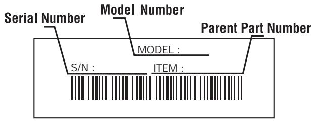
Copy the model and parent part number here:
Copy the serial number here:
Make sure you carefully read and understand this manual before starting or operating this equipment.
THIS PRODUCT IS COVERED BY ONE OR MORE U.S. PATENTS. OTHER PATENTS PENDING.
The purpose of safety symbols is to attract your attention to possible dangers. The safety symbols, and their explanations, deserve your careful attention and understanding. The safety warnings do not by themselves eliminate any danger. The instructions or warnings they give are not substitutes for proper accident prevention measures.
SYMBOL MEANING

SAFETY ALERT: Indicates danger, warning or caution. Attention is required in order to avoid serious personal injury. May be used in conjunction with other symbols or pictographs.
NOTE: Advises you of information or instructions vital to the operation or maintenance of the equipment.
SYMBOL MEANING

DANGER: Failure to obey a safety warning will result in serious injury to yourself or to others. Always follow the safety precautions to reduce the risk of fire, electric shock and personal injury.

WARNING: Failure to obey a safety warning can result in injury to yourself and others. Always follow the safety precautions to reduce the risk of fire, electric shock and personal injury.

CAUTION: Failure to obey a safety warning may result in property damage or personal injury to yourself or to others. Always follow the safety precautions to reduce the risk of fire, electric shock and personal injury.
- IMPORTANT SAFETY INSTRUCTIONS
READ ALL INSTRUCTIONS
BEFORE OPERATING

WARNING: When using the unit, you must follow the safety rules. Please read these instructions before operating the unit in order to ensure the safety of the operator and any bystanders. Please keep these instructions for later use.
- Read the instructions carefully. Be familiar with the controls and proper use of the unit.
- Do not operate this unit when tired, ill or under the influence of alcohol, drugs or medication.
- Children and teens under the age of 15 must not use the unit, except for teens guided by an adult.
- Inspect the unit before use. Replace damaged parts. Make sure all fasteners are in place and secure. Replace cutting attachment parts that are cracked, chipped or damaged in any way. Make sure the cutting attachment is properly installed and securely fastened. Be sure that the cutting attachment shield is properly attached, and positioned as recommended. Failure to do so can result in personal injury to the operator and bystanders, as well as damage to the unit.

DANGER: When using electric gardening appliances, basic safety precautions should always be followed to reduce the risk of fire, electric shock and personal injury. Carefully read and understand the entire operator's manual before using your unit. Pay close attention to the operating instructions and safety warnings.
- This unit was not designed to be used as a brushcutter. Do not attach or operate this unit with any type of brushcutting blade or brushcutting attachment.
- Use only a 0.080-inch (2.03 mm) diameter original equipment manufacturer replacement line. Never use metal-reinforced line, wire, chain or rope. These can break off and become dangerous projectiles.
- Be aware of risk of injury to the head, hands and feet.
- Clear the area to be cut before each use. Remove rocks, broken glass, nails, wire, string and other objects which may be thrown or become entangled in the cutting attachment. Clear the area of children, bystanders and pets; keep them outside a 50-foot (15 m.) radius, at a minimum. Even then, they are still at risk from thrown objects. Encourage bystanders to wear eye protection. If you are approached, stop the unit immediately.
ELECTRICAL SAFETY WARNINGS

WARNING: To reduce the risk of electrical shock, use only SW-A, SOW-A, STW-A, STOW-A, SJW-A, SJOW-A, SJTW-W or SJTOW-A cord types.
- Since the tool is double-insulated, a 2-wire extension cord (an extension cord without a ground) may be used. A 3-wire extension cord (an extension cord with a ground) that uses a NEMA type connector (parallel blade, U ground) is recommended. Extension cords are available from your local retailer. Use only round-jacketed extension cords approved for outdoor use.
- This tool is double-insulated. Repair or replace damaged cords.
- To reduce the risk of electrical shock, this unit has a polarized plug (one blade is wider than the other). This unit will fit with a polarized plug in one way only. If the plug does not fit fully into the unit, reverse the plug. If it still does not fit, use a cord with the correct connection. Do not modify the unit in any way.
| MINIMUM WIRE SIZE FOR EXTENSION CORDS FOR 120 VOLT APPLIANCES USING 0-12 AMPS* | ||||
| Cord length (ft.) | 25 | 50 | 100 | 150 |
| Wire size (AWG)* | 16 | 16 | 16 | 14 |
*The wire size (AWG) for appliances using 12 to 16 amps is 14 AWG for 25 feet, 12 AWG for 50 feet, and not recommended for 100 or 150 feet.
- CORD SETS: Make sure your cord set is in good condition, with a cord that is heavy enough to carry the current that your unit will draw. An undersized cord set will cause a drop in line voltage resulting in a loss of power, as well as overheating. The table shown above illustrates the correct size to use depending on the cord length and nameplate amperage rating. If in doubt, use the next heavier size line gauge. The smaller the gauge number, the heavier the cord. To prevent the cord from disconnecting from the unit, use the cord hook shown in the Operating Instructions.
- Ground Fault Circuit Interruption (GFCI) protection should be provided on the circuit(s) or outlet(s) that will be used for the unit. Use receptacles with built-in GFCI protection for an extra measure of safety.
- Do not abuse the power cord. Never carry the unit by the cord or yank the cord to disconnect from receptacle. Keep the cord from heat, oil and sharp edges.
- A nameplate on your unit indicates the voltage used. Never connect the unit to an AC voltage that differs from this voltage.
- Inspect all extension cords and the unit power connection periodically. Look closely for deterioration, cuts or cracks in the insulation. Also inspect the connections for damage. Repair or replace the cords if any defects appear.
- Avoid dangerous environments. Never operate your unit in damp or wet conditions. Moisture is a shock hazard.
- Do not use the unit in the rain.
- Do not handle the plug or the unit with wet hands.
WHILE OPERATING
- Wear safety glasses or goggles that are marked as meeting ANSI Z87.1-1989 standards. Also wear ear/hearing protection when operating this unit. Wear a face or dust mask if the operation is dusty. Long sleeve shirts are recommended.
-
Wear heavy, long pants, boots and gloves. Do not wear loose clothing, jewelry, short pants, sandals or go barefoot. Secure hair above shoulder level.
-
The cutting attachment shield must always be in place while operating the unit. Do not operate unit without both trimming lines extended, and the proper line installed. Do not extend the trimming line beyond the length of the shield.
- Adjust the D-handle to your size to provide the best grip.
- Be sure the cutting attachment is not in contact with anything before starting the unit.
- Use the unit only in daylight or good artificial light.
- Avoid accidental starting. Do not carry around a unit that is plugged in with your finger on the trigger switch. Be sure the switch is in the off position when plugging in the unit.
- Use the right tool. Only use this tool for its intended purpose.
- Do not overreach. Always keep proper footing and balance.
- Always hold the unit with both hands when operating. Keep a firm grip on both handles or grips.
- Keep hands, face, and feet at a distance from all moving parts. Do not touch or try to stop the cutting attachment when it rotates.
- Always stop the motor when cutting is delayed or when walking from one cutting location to another.
- If you strike or become entangled with a foreign object, stop the motor immediately and check for damage. Do not operate before repairing damage. Do not operate the unit with loose or damaged parts.
- Stop the unit and unplug it for maintenance or repair.
- Use only genuine original equipment manufacturer replacement parts and accessories for this unit. These are available from your authorized service dealer. Use of any non-original parts or accessories could lead to serious injury to the user, or damage to the unit, and void your warranty.
- Keep unit clean of vegetation and other materials. They may become lodged between the cutting attachment and shield.
OTHER SAFETY WARNINGS
- Be sure to secure the unit while transporting.
- Store the unit in a dry area, locked up to prevent unauthorized use or damage, and stored in a high place out of the reach of children.
- Never douse or squirt the unit with water or any other liquid. Keep handles dry, clean and free from debris. Clean after each use. See the Cleaning and Storage instructions.
- Keep these instructions. Refer to them often and use them to instruct other users. If you loan someone this unit, also loan them these instructions.
SAVE THESE INSTRUCTIONS
SAFETY AND INTERNATIONAL SYMBOLS
This operator's manual describes safety and international symbols and pictographs that may appear on this product. Read the operator's manual for complete safety, assembly, operating and maintenance and repair information.
SYMBOL MEANING

- SAFETY ALERT SYMBOL
Indicates danger, warning, or caution. May be used in conjunction with other symbols or pictographs.
SYMBOL MEANING
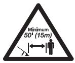
- KEEP BYSTANDERS AWAY
WARNING: Keep all bystanders, especially children and pets, at least 50 feet (15 m.) from the operating area.

WARNING - READ OPERATOR'S MANUAL
Read the Operator's Manual(s) and follow all warnings and safety instructions. Failure to do so can result in serious injury to the operator and/or bystanders.

- THROTTLE CONTROL Indicates "HIGH" or "FASTEST" speed.

- WEAR EYE AND HEARING PROTECTION
WARNING: Thrown objects and loud noise can cause severe eye injury and hearing loss. Wear eye protection meeting ANSI Z87.1-1989 standards and ear protection when operating this unit. Use a full face shield when needed.

- THROTTLE CONTROL
Indicates "IDLE", "LOW" or "SLOWEST" speed.

- DOUBLE INSULATED
Two systems of insulation are provided instead of grounding. There is no grounding provided and no means of grounding should be added to this unit.
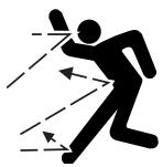
- THROWN OBJECTS AND ROTATING CUTTER CAN CAUSE SEVERE INJURY
WARNING: Do not operate without the cutting attachment shield in place. Keep away from the rotating cutting attachment.
- Cutting grass and light weeds
- Decorative trimming around trees, fences, etc.
Other optional accessories may be used with the TB32CS. Refer to Operating the EZ-Link System for a list of add-ons.
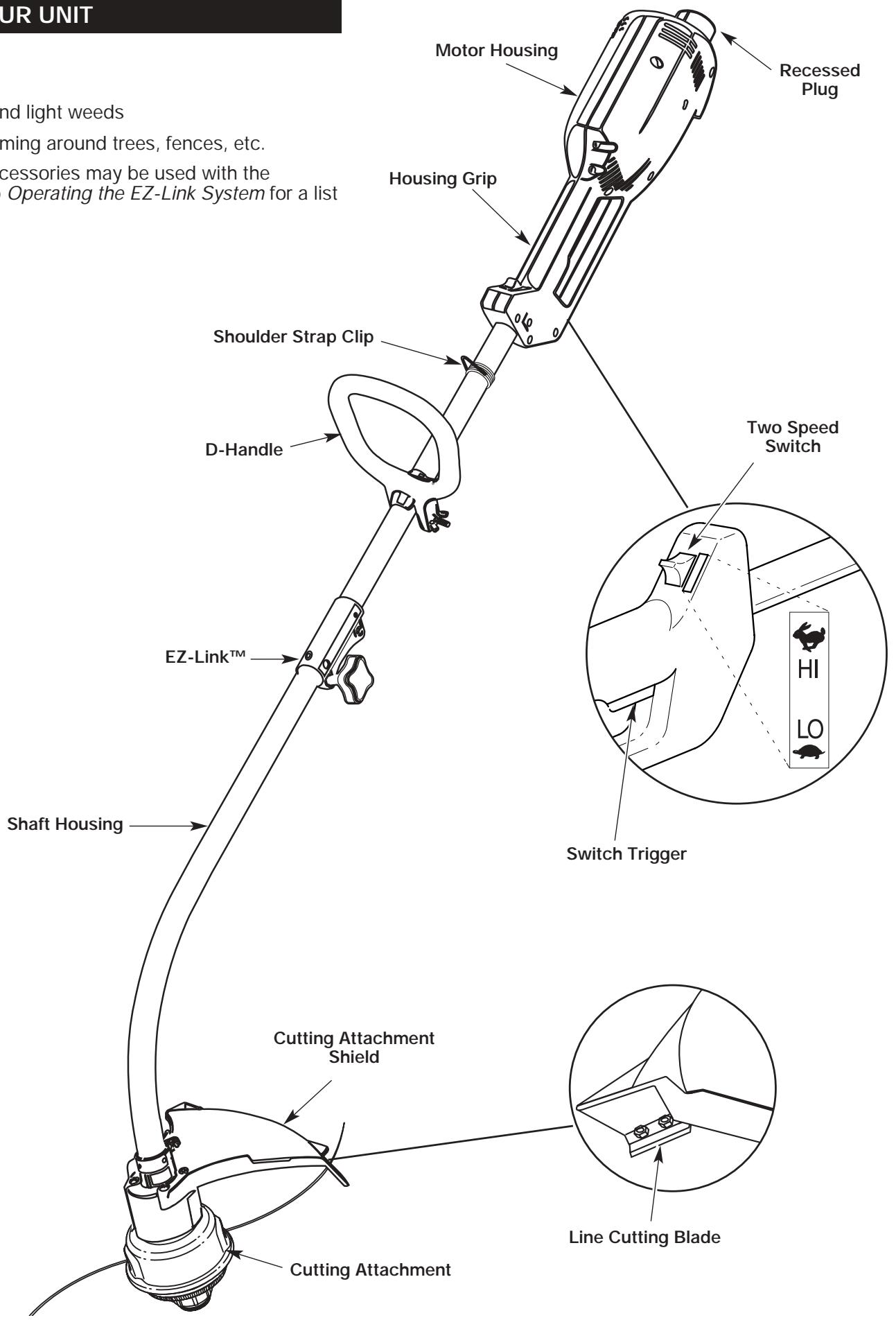
ASSEMBLY INSTRUCTIONS
INSTALL AND ADJUST THE D-HANDLE
- Push the D-handle down onto the shaft housing so that the handle slants towards the shaft grip (Fig. 1). The squared bolt hole in the handle is to the right.
- Insert the shoulder bolt into the squared hole in the handle and push through. On the left side of the handle, place the washer on the bolt, then screw the wing nut onto the bolt. Do not tighten until you make the handle adjustment.
- Rotate the D-handle to place the grip above the top of the shaft housing. Place it a minimum of 6 inches (15.24 cm) from the end of the housing.
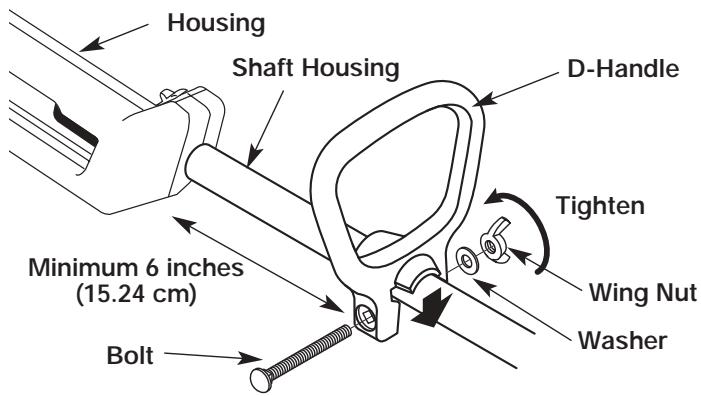
Fig. 1
- While holding the unit in the operating position (Fig. 2), position the D-handle to the location that provides you the best grip.
- Tighten the wing nut until the D-handle is secure.
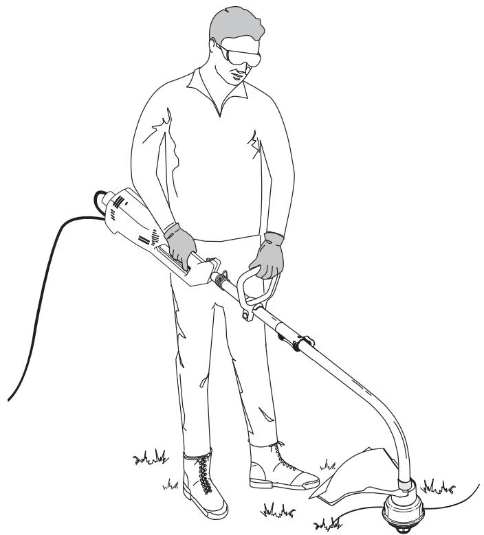
Fig. 2
INSTALLING THE CUTTING SHIELD
Use the following instructions if the cutting attachment shield on your unit is not installed or if you ever need to re-install it.

WARNING: Never operate the trimmer without the cutting attachment shield in place to prevent serious personal injury.
- Place the cutting attachment shield onto the shaft housing above the clamp assembly (Fig. 3).
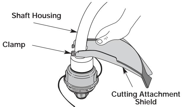
Fig. 3
- Push the cutting attachment shield down to the top of the cutting attachment assembly. Then rotate the shield until its screw holes line up with the holes in the cutting attachment. The shield guard should fit into the recessed pocket (Fig. 4).
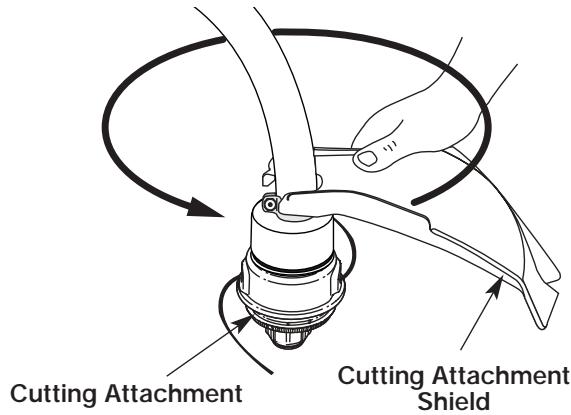
Fig. 4
- Install the screws with a Phillips screwdriver (Fig. 5).
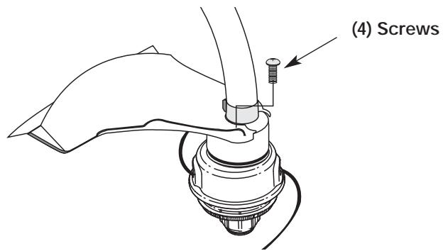
Fig. 5
OPERATING INSTRUCTIONS
WARNING: Before you begin using any
attachment, read and understand the manual that came with the attachment. Follow all safety information contained within.

WARNING: To avoid serious personal injury and
damage to the unit, shut the unit off before removing or installing add-ons.
Removing the Cutting Attachment or Add-Ons
- Turn the knob counterclockwise to loosen (Fig. 6).
- Press and hold the release button (Fig. 6).
- While firmly holding the upper shaft housing, pull the cutting attachment or add-on straight out of the EZ-Link™ coupler (Fig. 7).
Installing the Cutting Attachment or Add-Ons
NOTE: To make installing or removing the add-on easier, place the unit on the ground or on a work bench.
1. Turn knob counterclockwise to loosen (Fig. 6).
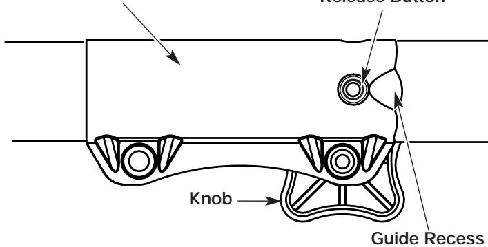
EZ-Link™ Coupler
Release Button
Fig. 6
- While firmly holding the add-on, push it straight into the EZ-Link™ coupler (Fig. 7).
NOTE: Aligning the release button with the guide recess will help installation (Fig. 6).
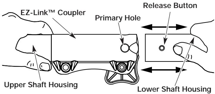
Fig. 7
- Turn the knob clockwise to tighten (Fig. 8).

CAUTION: Lock the release button in the primary hole (Fig. 10) and securely tighten the knob before operating this unit.
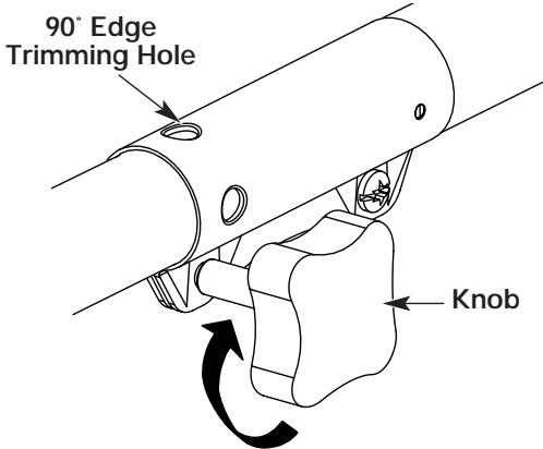
Fig. 8

CAUTION: The add-ons with the coupler system is to
be used in the primary hole only. Using the wrong hole could lead to personal injury or damage to the unit.
For decorative trimming/edging with the line head cutting attachment, lock the release button of the cutting attachment into the 90^ hole (Fig. 8).
OPERATING INSTRUCTIONS
CONNECTING THE CORD
Use the cord hook when connecting the extension cord to the power cord outlet. This helps prevent any disconnection.
- Make a narrow loop with the extension cord.
- Push the loop through the opening and move it onto the hook on the motor housing (Fig. 9).
- Plug the cord properly into the socket.
Only use outdoor-approved extension cords. Cord sets are specified in the Important Safety Information section.
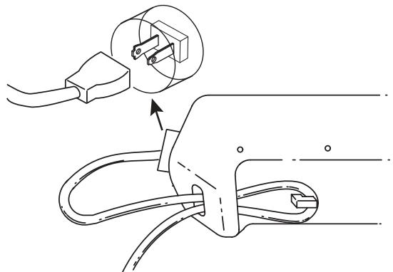
Fig. 9
STARTING/STOPPING INSTRUCTIONS
Once the unit is plugged in, stand in the operating position (Fig. 11). Squeeze the trigger to start the unit. To stop the unit, release the trigger (Fig. 10).

WARNING: Always wear eye, hearing, foot and body protection to reduce the risk of injury when operating this unit.
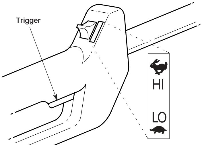
Fig. 10
This unit is equipped with a two-speed switch. The switch has a powerful high speed for demanding yard work, and a precision low speed for light-duty yard work.
Push the switch up for high speed trimming, down for low speed trimming (Fig. 10).

CAUTION: Do not use the unit for demanding work with the switch in the low speed. This could cause overheating and failure.
HOLDING THE UNIT
Before operating the unit, stand in the operating position (Fig. 11). Check for the following:
- The operator is wearing eye protection and proper clothing
- With a slightly-bent right arm, the operator's hand is holding the shaft grip
- The operator's left arm is straight, the left hand holding the D-handle
The unit is at waist level - The cutting attachment is parallel to the ground and easily contacts the grass without the need to bend over
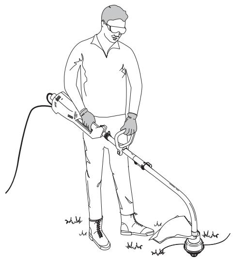
Fig. 11
ADJUSTING TRIMMING LINE LENGTH
The Bump Head™ cutting attachment allows you to release trimming line without stopping the motor. To release more line, lightly tap the cutting attachment on the ground (Fig. 12) while operating the trimmer at high speed.
NOTE: Always keep the trimming line fully extended. Line release becomes more difficult as cutting line becomes shorter
Each time the head is bumped, about 1 inch (25.4 mm) of trimming line releases. A blade in the cutting attachment shield will cut the line to the proper length if any excess line is released.
OPERATING INSTRUCTIONS
For best results, tap the bump knob on bare ground or hard soil. If you attempt a line release in tall grass, the motor may stall. Always keep the trimming line fully extended. Line release becomes more difficult when the cutting line gets shorter.
NOTE: Do not rest the Bump Head™ on the ground while the unit is running.

CAUTION: Do not remove or alter the line cutting blade assembly. Excessive line length will make the clutch overheat. This may lead to serious personal injury or damage to the unit.
Some line breakage will occur from:
- Entanglement with foreign matter
Normal line fatigue - Attempting to cut thick, stalky weeds
- Forcing the line into objects such as walls or fence posts
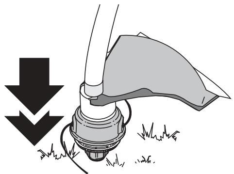
Fig. 12
TIPS FOR BEST TRIMMING RESULTS
- Keep the cutting attachment parallel to the ground.
- Do not force the cutting attachment. Allow the tip of the line to do the cutting, especially along walls. Cutting with more than the tip will reduce cutting efficiency and may overload the motor.
-
Cut grass over 8 inches (200 mm) by working from top to bottom in small increments to avoid premature line wear or motor drag.
-
Cut from right to left whenever possible. Cutting to the left improves the unit's cutting efficiency. Clippings are thrown away from the operator.
- Slowly move the trimmer into and out of the cutting area at the desired height. Move either in a forward-backward or side-to-side motion. Cutting shorter lengths produces the best results.
- Trim only when grass and weeds are dry.
-
The life of your cutting line is dependent upon:
-
Following the trimming techniques previously explained
- What vegetation is cut
- Where vegetation is cut
For example, the line will wear faster when trimming against a foundation wall as opposed to trimming around a tree.
DECORATIVE TRIMMING
Decorative trimming is accomplished by removing all vegetation around trees, posts, fences and more.
Rotate the whole unit so that the cutting attachment is at a 30^ angle to the ground (Fig. 13).
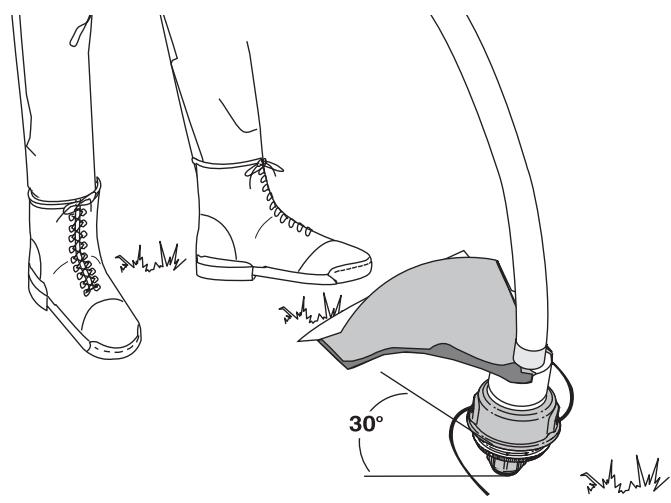
Fig. 13
MAINTENANCE AND REPAIR INSTRUCTIONS
SERVICING DOUBLE INSULATED UNITS
This unit is double-insulated. In a double-insulated unit, two systems of insulation are provided instead of grounding. There is no grounding provided and no means of grounding should be added to this unit.
Extreme care and knowledge of the system is required when servicing a double-insulated unit. Service should be performed by qualified service personnel only. Replacement parts for a double-insulated unit must be identical to the parts they replace. Refer any repair to an authorized service dealer. A double-insulated unit is marked with the words "double insulation" or "double insulated."
LINE INSTALLATION FOR THE SPEEDSPOOL®
Always use a genuine factory 0.080 inch (2.03 mm) replacement line. Lines other than those specified may make the unit overheat or fail.

WARNING: Never use metal-reinforced line, wire, chain or rope. These can break off and become dangerous projectiles.
There are two methods to replace the SpeedSpool® trimming line:
- Wind the inner reel with new line
Install a pre-wound inner reel
Winding the Inner Reel With New Line
NOTE: It Is unnecessary to remove the bump knob to install a new trimming line.
- Cut two pieces of 0.080 inch (2.03 mm) trimming line, 10 feet (3 m) long.
- Hold the outer spool and turn the inner reel counterclockwise to line up the arrows on the outer spool and inner reel (Fig. 14).

WARNING: Always use the correct line length when installing trimming line on the unit. The line may not release properly if the line is too long.
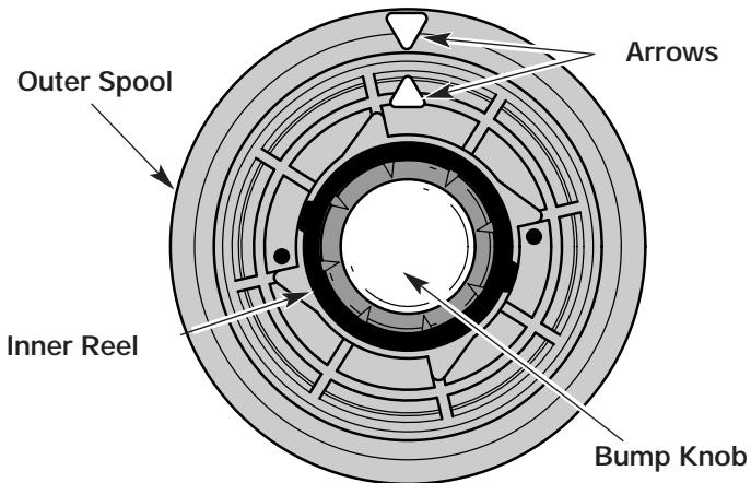
Top View Of The SpeedSpool®
Fig. 14
- Pull old line out of the line loading and line locking holes (Fig. 15 and 16).
- Insert a piece of trimming line into one of the two eyelets in the outer spool. Push it up through the line loading hole in the inner reel (Fig. 15). Do not bend the line when inserting it into the eyelet.
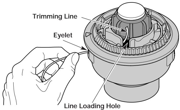
Fig. 15
- Insert the line into the locking hole (Fig. 16). Do not push the line more than 12 inch (12.7 mm) into the line locking hole. When inserted correctly the line will form a small loop (Fig. 16).
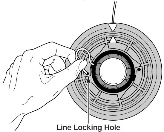
Fig. 16
- Pull the line from the outer spool until the line is tight against the inner reel (Fig. 17).
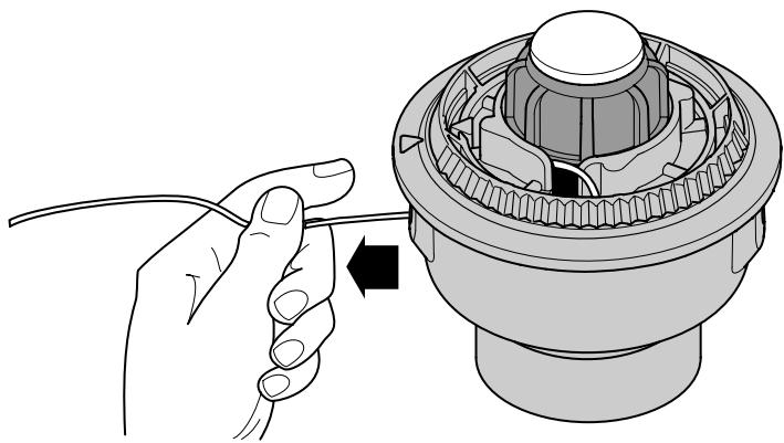
Fig. 17
MAINTENANCE AND REPAIR INSTRUCTIONS
- Repeat procedures 4-6 with the second piece of line.
- Hold the outer spool. Wind the inner reel counterclockwise until approximately four (4) inches (102 mm) of line remain (Fig. 18).
NOTE: Do not wind the inner reel before installing the second piece of line.
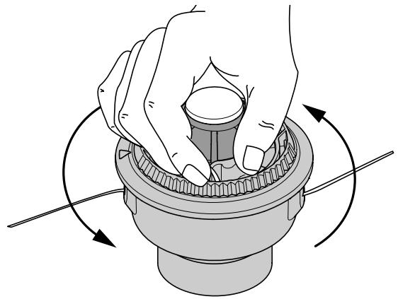
Fig. 18
- If winding the line becomes difficult or the line jams, pull the ends of the line from the spool (Fig. 19). Continue winding the inner reel counterclockwise.
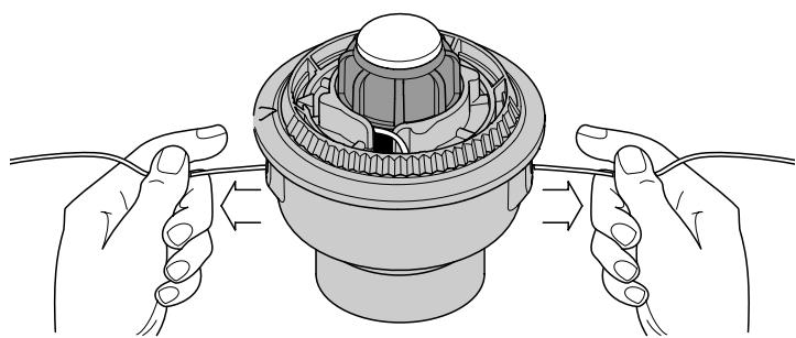
Fig. 19
INSTALLING A PREWOUND REEL
- Turn the Bump Knob counterclockwise and remove the bump knob, spring and foam seal (Fig. 20).
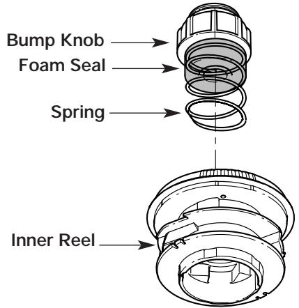
Fig. 20
- Pull the old inner reel with existing line from the outer spool.
- Insert the ends of the prewound inner reel line into the outer spool eyelets (Fig. 21). Push the new inner reel, arrow side up, into the outer spool.
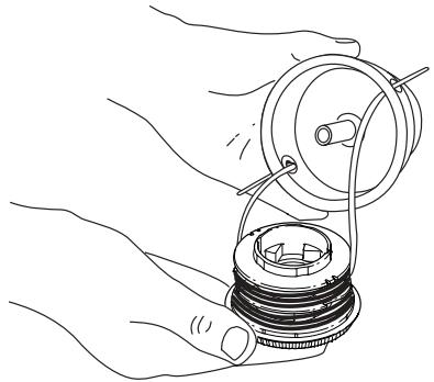
Fig. 21
- Hold the inner reel in place and install the bump knob, spring and foam seal. Press down and turn the bump knob clockwise. Grasp the ends and pull firmly to release the line from the holding slots in the inner reel (Fig. 19).
Releasing the Inner Reel
If the SpeedSpool® does not release line correctly, pull the ends of the line firmly from the spool (Fig. 19). If this does not the release line, follow the Cleaning the SpeedSpool® instructions.
CLEANING THE SPEEDSPOOL®
Cleaning the SpeedSpool® may be necessary if:
- A jammed or excessive line must be removed
-
The SpeedSpool® becomes difficult to wind or does not operate correctly when bumping the head on the ground
-
Hold the outer spool, and unscrew the bump knob counterclockwise (Fig. 22).
- Pull out the bump knob, spring and foam seal (Fig. 20).
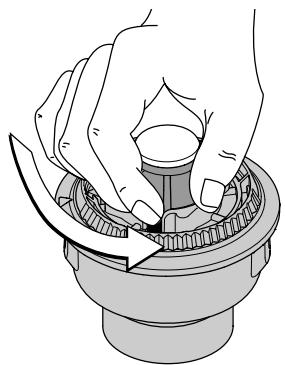
Fig. 22
- Pull the inner reel with existing line from the outer spool (Fig. 21).
- Remove any existing line from the inner reel before cleaning. Remove any debris or grass from the knob, spring, inner reel and foam seal. Wash the inner reel with warm soapy water (Fig. 23).
MAINTENANCE AND REPAIR INSTRUCTIONS
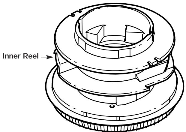
Fig. 23
- Clean the shaft and the inner surface of the outer spool. To clean the shaft underneath the plunger, press down on the plunger (Fig. 24). Remove any dirt or debris from the shaft.
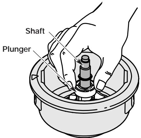
Fig. 24
NOTE: The inner reel must be totally dry before reinstalling it into the outer spool. Do not lubricate the inner reel or outer spool assembly.
- Place the inner reel into the outer spool.
- Place the bump knob, spring and foam seal into the inner reel (Fig. 20).
- Press the bump knob down and tighten clockwise.
- Install new line as described in Line Installation for the SpeedSpool®.
CLEANING

WARNING: To avoid serious personal injury, always turn your unit off and unplug it before you clean or service it.
Switch off the unit and disconnect it from the power source. Use a small brush to clean off the outside of the unit. Do not use strong detergents. Household cleaners that contain aromatic oils such as pine and lemon, and solvents such as kerosene, can damage plastic housing or handle. Wipe off any moisture with a soft cloth. Also keep the air vents free of obstructions.
INSPECT EXTENSION CORDS
Inspect all extension cords. Look closely for deterioration, cuts or cracks in the insulation. Inspect the connectors for damage. Replace a damaged or defective cord.
STORAGE
- Allow the unit to cool before storing.
- Lock the unit to prevent unauthorized use or damage.
- Store the unit in a dry, well-ventilated area.
- Store the unit out of the reach of children.
TROUBLESHOOTING
MOTOR WILL NOT START
CAUSE
Unit is unplugged
Overload protection switch has popped
ACTION
Check cord to make sure it is still plugged into an electrical outlet
Reset overload protection switch
CUTTING ATTACHMENT WILL NOT ADVANCE LINE
CAUSE
Cutting attachment bound with grass
Cutting attachment out of line
Inner reel bound up
Cutting head dirty
Line welded
Line twisted when refilled
Not enough line is exposed
ACTION
Stop the unit and clean cutting attachment
Refill with new line
Replace the inner reel
Clean inner reel and outer spool
Disassemble, remove the welded section and rewind
Disassemble and rewind the line
Push the bump knob and pull out line until 4 inches (102 mm) of line
is outside of the cutting attachment
CUTTING LINE ADVANCES UNCONTROLLABLY
CAUSE
Oil, cleaner or lubricant in cutting head
ACTION
Clean and thoroughly dry the cutting head
If further assistance is required, contact your authorized service dealer.
SPECIFICATIONS
MOTOR
Motor type. A.C., 120 Volts Electric
Operating RPM . up to 7,400 rpm
On/Off Switch Trigger
Amperage 5.2 amps
DRIVE SHAFT AND CUTTING HEAD
Drive Shaft Housing Steel, EZ-Link
Unit Weight (With cutting attachment, cutting attachment shield and D-handle) 13 lbs. (5.9 kg)
Cutting Mechanism SpeedSpool® Dual String Cutting Head
Line Spool . Bump Line Releaser
Line Spool Diameter 3 inches (76.2 mm)
Trimming Line Diameter 0.080 in (2.03 mm)
Cutting Path Diameter 15 in (381 mm)
MANUFACTURER'S LIMITED WARRANTY FOR:
TROY-BILT®
The limited warranty set forth below is given by Troy-Bilt LLC with respect to new merchandise purchased and used in the United States, its possessions and territories.
Troy-Bilt LLC warrants this product against defects in material and workmanship for a period of two (2) years commencing on the date of original purchase and will, at its option, repair or replace, free of charge, any part found to be defective in material or workmanship. This limited warranty shall only apply if this product has been operated and maintained in accordance with the Operator's Manual furnished with the product, and has not been subject to misuse, abuse, commercial use, neglect, accident, improper maintenance, alteration, vandalism, theft, fire, water or damage because of other peril or natural disaster. Damage resulting from the installation or use of any accessory or attachment not approved by Troy-Bilt LLC for use with the product(s) covered by this manual will void your warranty as to any resulting damage. This warranty is limited to ninety (90) days from the date of original retail purchase for any Troy-Bilt product that is used for rental or commercial purposes, or any other income-producing purpose.
HOW TO OBTAIN SERVICE: Warranty service is available, WITH PROOF OF PURCHASE THROUGH YOUR LOCAL AUTHORIZED SERVICE DEALER. To locate the dealer in your area, visit our website at www.troybilt.com, check for a listing in the Yellow Pages, call 1 (866) 840-6483 or 1 (330) 558-7220 or write to P.O. Box 361131, Cleveland, OH 44136-0019.
This limited warranty does not provide coverage in the following cases:
A. Tune-ups - Spark Plugs, Carburetor Adjustments, Filters
B. Wear items - Bump Knobs, Outer Spools, Cutting Line, Inner Reels, Starter Pulley, Starter Ropes, Drive Belts
C. Troy-Bilt LLC does not extend any warranty for products sold or exported outside of the United States of America, its possessions and territories, except those sold through Troy-Bilt's authorized channels of export distribution.
Troy-Bilt LLC reserves the right to change or improve the design of any Troy-Bilt Product without assuming any obligation to modify any product previously manufactured.
No implied warranty, including any implied warranty of merchantability or fitness for a particular purpose, applies after the applicable period of express written warranty above as to the parts as identified. No other express warranty or guaranty, whether written or oral, except as mentioned above, given by any person or entity, including a dealer or retailer, with respect to any product shall bind Troy-Bilt LLC During the period of the Warranty, the exclusive remedy is repair or replacement of the product as set forth above. (Some states do not allow limitations on how long an implied warranty lasts, so the above limitation may not apply to you.)
The provisions as set forth in this Warranty provide the sole and exclusive remedy arising from the sales. TroyBilt LLC shall not be liable for incidental or consequential loss or damages including, without limitation, expenses incurred for substitute or replacement lawn care services, for transportation or for related expenses, or for rental expenses to temporarily replace a warranted product. (Some states do not allow limitations on how long an implied warranty lasts, so the above limitation may not apply to you.)
In no event shall recovery of any kind be greater than the amount of the purchase price of the product sold. Alteration of the safety features of the product shall void this Warranty. You assume the risk and liability for loss, damage, or injury to you and your property and/or to others and their property arising out of the use or misuse or inability to use the product.
This limited warranty shall not extend to anyone other than the original purchaser, original lessee or the person for whom it was purchased as a gift.
How State Law Relates to this Warranty: This warranty gives you specific legal rights, and you may also have other rights which vary from state to state.
To locate your nearest service dealer dial 1 (866) 840-6483.
Troy-Bilt LLC
P.O. Box 361131
Cleveland, OH 44136-0019
TROY-BILT®
RÉFERENCES, ILLUSTRATIONS ET SPECIFICATIONS RELATIVES AU PRODUIT
Item Part No. Description
1 791-180300 Screw, Housing Set
2 791-145569 Anti-Rotation Screw
3 753-04273 Motor Housing Assembly
4 753-04274 Two-Speed Switch Assembly
5 791-180559 Lead Wires
6 791-180150 Switch (includes 7)
7 791-182318 Trigger
8 791-180305 Terminal Block
9 791-180154 Motor Assembly (includes 10-11)
10 791-180152 Driver
791-180155 Cooling Fan
791-181645 Power Cord Assembly

CAUTION: Only authorized service technicians
should perform adjustments to double-insulated units.
BOOM AND TRIMMER PARTS - MODEL TB32CS 120 VOLT ELECTRIC TRIMMER
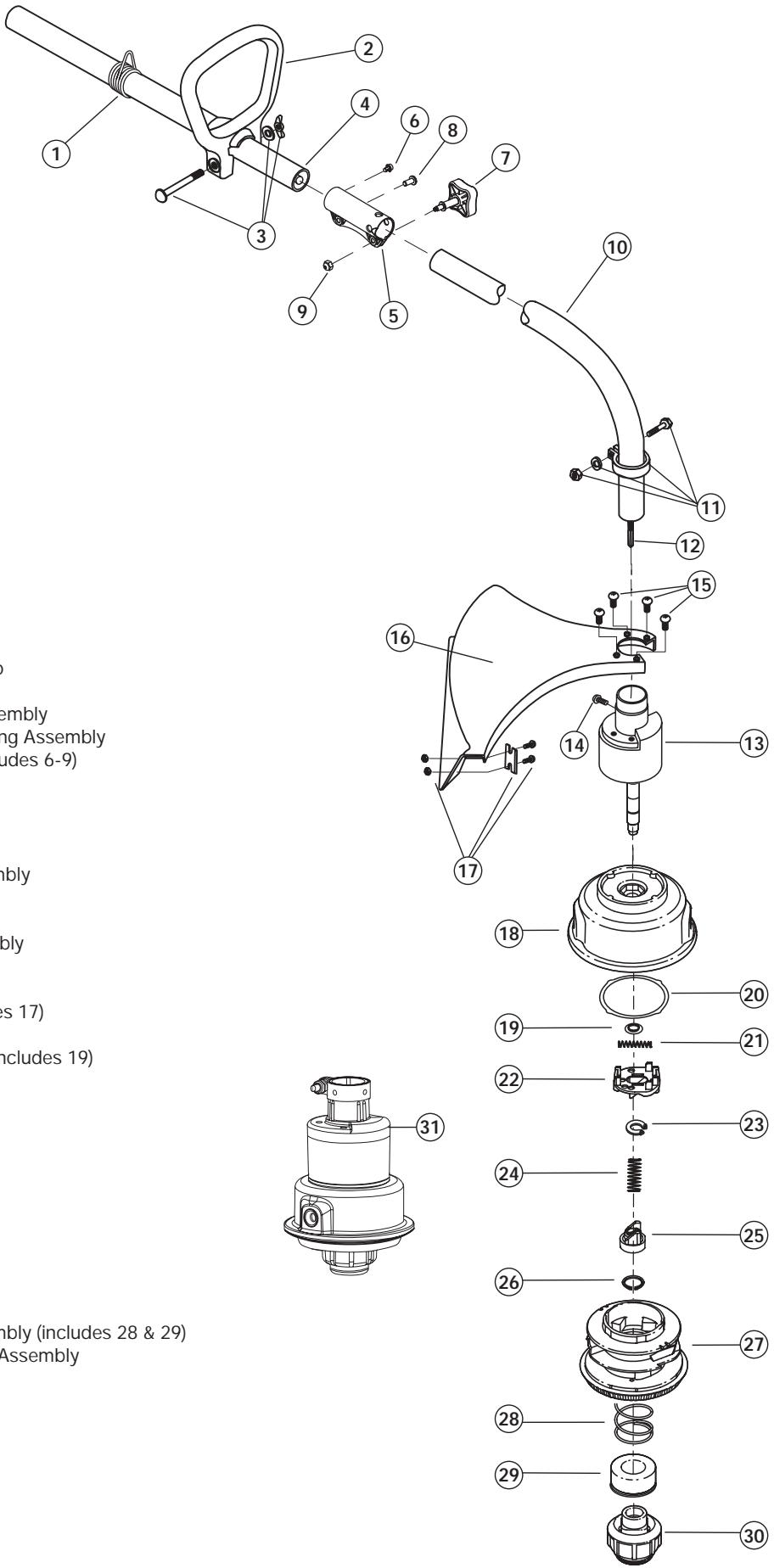
Item Part No. Description
1 791-610327
2 791-153064
3 791-181587
4 753-04345
5 791-182928
6 791-182057 S6
7 791-181951
8 791-181617 Bolt
9 753-04386 Nut
10 753-1218
11 791-153597
12 791-181852
13 791-181857
14 791-145569
15 791-180531
16 791-683274
17 791-682061
18 791-181457
791-181458 Retainer
20 791-181561 Thrust Washer
21 791-181459
22 753-04257
23 791-181532
24 791-181531
25 791-181462
26 791-181463
27 791-181464
28 791-181465
29 791-181467
30 791-181468
31 791-181469
Description
Shoulder Harness Clamp
D-Handle (includes 3)
D-Handle Hardware Assembly
Upper Drive Shaft Housing Assembly
Split Boom Coupler (includes 6-9)
Screw
Adjustment Knob
Bolt
Nut
Lower Drive Shaft Assembly
Lower Clamp Assembly
Flexible Drive Shaft
Bushing Housing Assembly
Anti-Rotation Screw
Guard Mounting Screws
Guard Assembly (includes 17)
Blade Assembly
Outer Spool Assembly (includes 19)
Retainer
Thrust Washer
Small Spring
Slider
E-Clip
Spring
Plunger
C-Clip
Inner Reel
Large Spring
Foam Seal
Bump Head Knob Assembly (includes 28 & 29)
Complete Cutting Head Assembly
(includes 11 & 13-30)
Optional Accessories
- 791-682075 Shoulder Strap Harness
- 791-181460 Reel w/.080 Line
* not shown