
OHD-190-180 - Lawn mower MTD - Free user manual and instructions
Find the device manual for free OHD-190-180 MTD in PDF.


| Product Type | Two-bag grass collector for lawn tractor |
| Brand | MTD |
| Model | OHD-190-180 |
| Collection Capacity | 2 grass bags |
| Compatible Cutting Width | 97 cm and 106 cm |
| Attachment System | FastAttach™ |
| Bag Material | Durable fabric with frame |
| Weight (estimated) | Approx. 15 kg |
| Collector Dimensions (L x W x H) | Approx. 120 x 60 x 50 cm |
| Power Supply | Not applicable (mechanical accessory) |
| Main Functions | Collection of cut grass, side discharge via chute |
| Maintenance and Cleaning | Empty bags after use, clean chute and tube |
| Safety | Disengage PTO, stop engine and engage parking brake before any intervention |
| Spare Parts and Repairability | Complete parts list available in manual; contact MTD at 1-800-800-7310 |
| General Information | Free user manual and instructions available online |
Frequently Asked Questions - OHD-190-180 MTD
User questions about OHD-190-180 MTD
0 question about this device. Answer the ones you know or ask your own.
Ask a new question about this device
Download the instructions for your Lawn mower in PDF format for free! Find your manual OHD-190-180 - MTD and take your electronic device back in hand. On this page are published all the documents necessary for the use of your device. OHD-190-180 by MTD.
USER MANUAL OHD-190-180 MTD
Twin Rear Bagger Kit
For Lawn Tractors
with 38” & 42” Decks
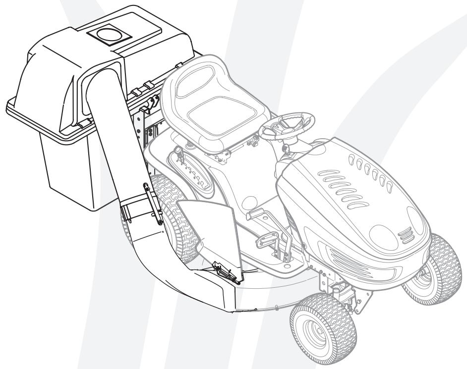
Models OHD-190-180
IMPORTANT
READ SAFETY RULES AND INSTRUCTIONS CAREFULLY BEFORE OPERATION
This Operator's Manual is an important part of your new grass collector. It will help you assemble, prepare and maintain the unit for best performance. Please read and understand what it says.
TABLE OF CONTENTS
- Rider Identification.. 5. Attach Discharge Chute.. Page 10
- Carton Contents Page 4 6. Parts List Page 12
- Bracket Assembly.. 7. Notes Page 14
- Attach Grass Bags.. Page 9 Warranty.. Page 16
Finding and Recording Model Number
BEFORE YOU START ASSEMBLING YOUR NEW EQUIPMENT,
please locate the model plate and copy the information from it in this Operator's Manual for future reference. The information on the model plate is very important if you need help from our Customer Support Department or your authorized dealer.
You can locate it by looking on the front, left portion of the plastic grass catcher cover as seen below:
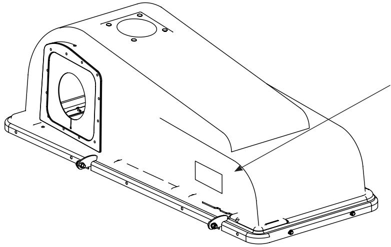
Model Number
Serial Number

www.mtdproducts.com
MTD LLC
P.O. BOX 361131
CLEVELAND, OH 44136
330-220-4683
800-800-7310
*Locate the model plate on your dagger and copy the information from it in the space provided above for future reference.
Customer Support
Please do NOT return the unit to the retailer from which it was purchased, without first contacting Customer Support.
If you have difficulty assembling this product or have any questions regarding the controls, operation, or maintenance of this unit, you can seek help from the experts. Choose from the options below:
- Visit www.mtdproducts.com. Click on the Service & Support menu option.
- Phone a Customer Support Representative at 1-800-800-7310.
- Please have your unit's model number and serial number ready when you call. See above to locate this information. You will be asked to enter the serial number in order to process your call.

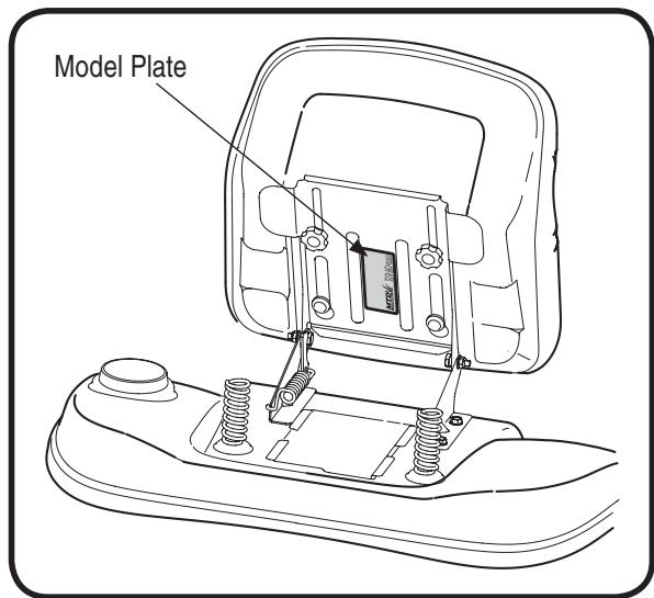
Figure 2
Figure 1
Sample Model Number
13AM790G000 Indicates Model Series 700
FastAttach™ Twin Bag Grass Collector
The Model OEM-190-180 Twin Bag Grass Collector is a grass collection system designed for use on all MTD 38" & 42" cut FastAttach™ compatible lawn tractors (except 2001 Yard-Man Revolution/White Outdoor ZTT).
The instructions in this manual are divided into sections. Carefully read all sections pertaining to your model of rider, and study the illustrations to ensure proper installation and usage of this attachment. Read and observe all WARNING, NOTES and IMPORTANT statements. They are included to provide for the protection of the equipment installer and user, and to ensure the prolonged service life of the equipment.
NOTE: References to LEFT and RIGHT indicate the left and right sides of the tractor when facing forward in the operator's position. Reference to the FRONT indicates the grille end; to the REAR, the rear end of the rider.
Determine The Model of Your Rider
Since this manual is designed for installation of your new dagger on several different rider units, it is important for you to determine which model of rider you have. Therefore you will know which set of instructions in the following pages to follow.
To determine which model of rider you have, you will need to locate the rider's model plate, located under the seat. Simply flip the seat up and locate the model plate, which will consist of an 11 digit/letter model number and a serial number. For ease in this installation and for future use, copy your rider's model number & serial number below now:
Rider Model Number:
Rider Serial Number:
The 5th , 6th & 7th numbers from the left in your model number determine your rider's model series. See Figure 2.
When you fill in your model number in the space above, the actual model series number should fall into the gray shaded area.
Now that you have determined what model rider you are attaching this grass bag collection system to, follow the instructions on the following pages according to your model of rider.

Rider Model Identification

NOTE:
References to LEFT and RIGHT indicate the left and right sides of the tractor when facing forward in the operator's position. Reference to the FRONT indicates the grille end; to the REAR, the rear end of the rider.

Carton Contents

If you are missing any parts, please do not contact the retailer where you purchased this unit, call MTD directly at 1-330-220-4MTD or toll free at 1-800-800-7310.
CONTENTS OF CARTON
Before beginning installation, remove all parts from the carton to make sure everything is present. Carton contents are listed below and shown in Figure 3. Hardware part numbers are shown in parentheses.
One Chute Tube
One Support Tube
One Discharge Chute Assembly
One Grass Catcher Cover Assembly
Two Grass Bag Assemblies
One Mounting Bracket

Figure 3
CONTENTS OF HARDWARE PACK
This grass collector kit is shipped with a hardware pack enclosed. This hardware pack may contain extra parts for installation on a different rider from which you have. Please check your hardware pack against the illustration below in accordance with your model of rider as determined in Section 1 of this manual.
For all Model Series 650 through 699 tractors
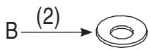
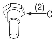
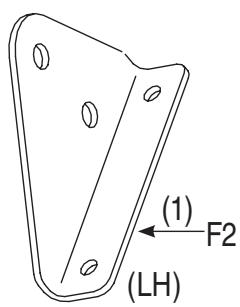
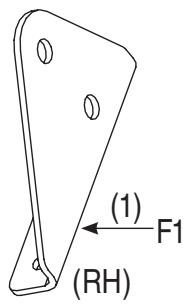
For all Model Series 700 tractors
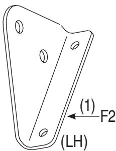
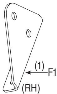
For older tractors only
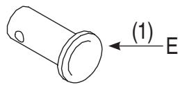
For decks with grass catcher pin not pre-installed
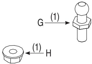
Figure 4
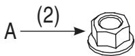
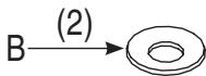
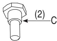
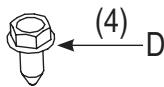
NOTE: Each item has been identified in above for ease of assembly, and the letter code assigned here is maintained in assembly instructions.
RH = Right Hand
(#) = Quantity
If you are missing any parts, please do not contact the retailer where you purchased this unit, call MTD directly at 1-330-220-4MTD or toll free at 1-800-800-7310.
NOTE: Each item has been identified in above for ease of assembly, and the letter code assigned here is maintained in assembly instructions.
RH = Right Hand
LH = Left Hand
(#) = Quantity

Attaching Bracket Assembly
Model Series 600 through 619

IMPORTANT:
Before assembly, place the tractor on a firm, level surface, disengage the PTO, stop the tractor engine and set the parking brake.
NOTE:
There are two holes in the clevis pin. Be sure to insert the hairpin clip in the upper hole to properly secure the bracket assembly to the hitch plate.
Attaching The Bracket Assembly
Model Series 600 through 619
IMPORTANT: Before assembly, place the tractor on a firm, level surface, disengage the PTO, stop the tractor engine and set the parking brake.
- For convenience, pivot the seat forward and leave it in that position until the grass collector is fully mounted and assembled.
- Remove the hairpin clip and clevis pin from the rear of the mounting bracket assembly. See Figure 5.
- Position the hooked ends of the bracket assembly over the shoulder bolts (1). Swing in the bottom of the bracket assembly down and in (2) over the hitch plate and aligning with the hole on the hitch plate. See Figure 5.
- Reinsert the clevis pin through the aligned holes in both the bracket assembly and the hitch plate and secure with the hairpin clip removed earlier. Refer to Figure 6.
NOTE: There are two holes in the clevis pin. Be sure to insert the hairpin clip in the upper hole to properly secure the bracket assembly to the hitch plate.
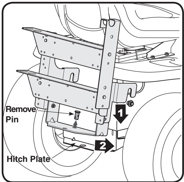
Figure 5
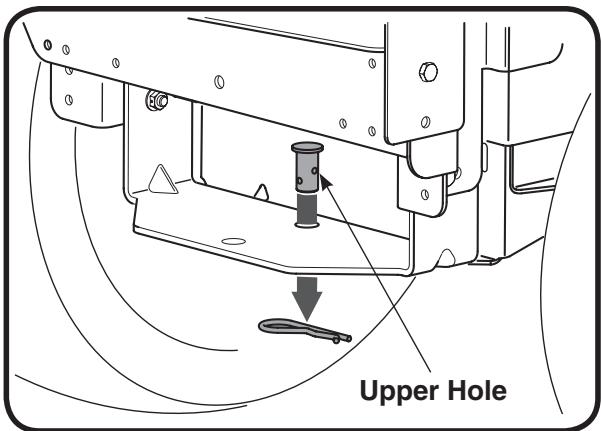
Figure 6
Model Series 650 through 699
This graphic below coordinates with the instructions for the Model Series 650 through 699, which begin on the next page.
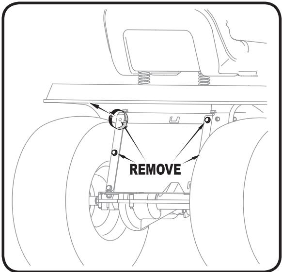
Figure 7
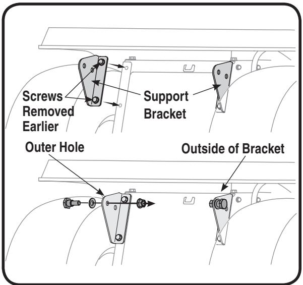
Figure 8
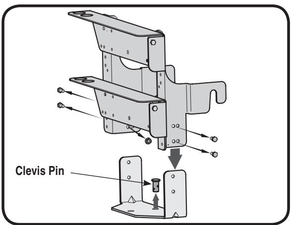
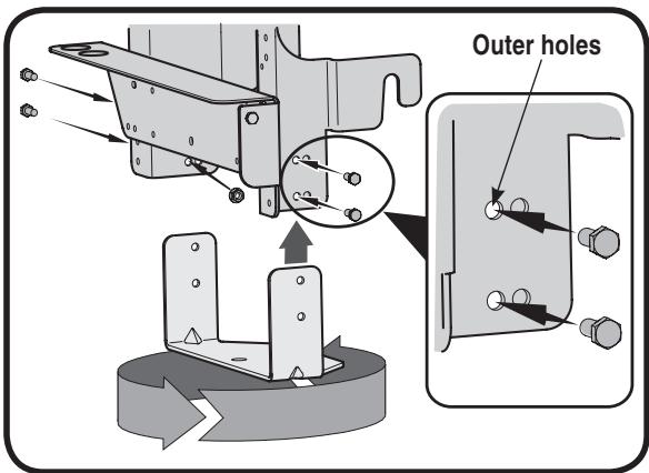
Figure 9
Figure 10
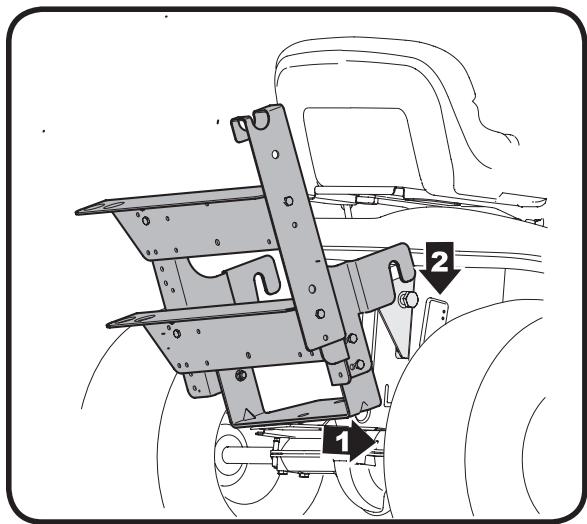
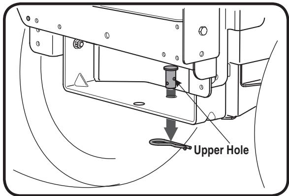
Figure 11
Figure 12
Assembling Support Brackets
Model Series 650 through 699
IMPORTANT: Before assembly, place the tractor on a firm, level surface, disengage the PTO, stop the tractor engine and set the parking brake.
- Remove the top four self-tapping screws from the rear of the lawn tractor. See Figure 7 on the previous page.
- Place the right hand grass catcher support bracket (F1 from Figure 4), in position, with the wide end on top and the narrow end pointing down as shown in Figure 8.
- Secure the support bracket to the tractor frame with two self-tapping screws earlier removed. Refer to Figure 8. Repeat on the other side using part F2 from Figure 4.
NOTE: If the grass collection system is removed for any reason, it is not necessary to remove the support brackets from the tractor.
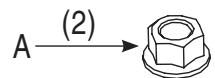
4. Insert a shoulder bolt (C in Figure 4) through a bell washer, (B in Figure 4) and insert the bolt from the outside of the bracket through the outer hole on the support bracket. Secure with a nut (A in Figure 4). See Figure 8 for details. Repeat on other side.
NOTE: The reference above to "the outer hole" means the hole furthest away from the frame.
Attaching Bracket Assembly
Model Series 650 through 699
- Remove the two nuts and bolts on each side of the mounting bracket holding the hitch plate.
- Rotate the hitch plate 180° from its original position. Re-insert the four bolts through mounting bracket and hitch plate frame and secure with nuts removed earlier. Use the outer holes (furthest from the mounting hooks) on the mounting bracket. See Figure 10.
- For convenience, pivot the seat forward and leave it in that position until the grass collector is fully mounted and assembled.
- Remove the hairpin clip and clevis pin from the rear of the mounting bracket assembly. See Figure 9.
- Position the hooked ends of the mounting bracket assembly to the outside of the support brackets and over the shoulder bolts just installed on both sides of the tractor frame. See Figure 11.
- Reinsert the clevis pin through the aligned holes in both the bracket assembly and the hitch plate and secure with the hairpin clip removed earlier. See Figure 12 for reference.
IMPORTANT: There are two holes in the clevis pin. Be sure to insert the hairpin clip in the upper hole to properly secure the bracket assembly to the hitch plate.
NOTE: For some tractor models, this clevis pin is too large. Use a smaller clevis pin (E in Figure 4) in

Attaching Support Bracket & Bracket Assembly
Model Series 650 through 699

IMPORTANT:
Before assembly, place the tractor on a firm, level surface, disengage the PTO, turn off tractor engine and set the parking brake.
NOTE:
If the grass collection system is removed for any reason, it is not necessary to remove the support brackets from the tractor.
IMPORTANT:
There are two holes in the clevis pin. Be sure to insert the hairpin clip in the upper hole to properly secure the bracket assembly to the hitch plate.
NOTE:
For some tractor models, this clevis pin is too large. Use a smaller clevis pin in its place with the same hairpin clip.
3
Attaching Support Bracket & Bracket Assembly
Model Series 700

NOTE:
If the grass collection system is removed for any reason, it is not necessary to remove the support brackets from the tractor.
IMPORTANT:
There are two holes in the clevis pin. Be sure to insert the hairpin clip in the upper hole to properly secure the bracket assembly to the hitch plate.
Assembling Support Brackets
Model Series 700
- Locate the four self-tapping screws supplied in your hardware pack (D from Figure 4). Attach the right hand grass catcher support bracket (F1 from Figure 4) using two of the supplied screws in position as shown in Figure 13. Place the left hand grass catcher support bracket (F2 from Figure 4) in position and secure with the other two screws.
- Insert a shoulder bolt (C in Figure 4) through a bell washer, (B in Figure 4) and insert the bolt through the Inner hole (closest to the frame) on the outside of the support bracket. Secure with a nut (A in Figure 4). See Figure 13 for details. Repeat on other side.
NOTE: If the grass collection system is removed for any reason, it is not necessary to remove the support brackets from the tractor.
Attaching The Bracket Assembly
- Remove the two nuts and screws on each side of the mounting bracket holding the hitch plate. See Figure 14.
- Rotate the hitch plate 180° from its original position. Re-insert the four bolts through mounting bracket and hitch plate frame and secure with nuts removed earlier. Use the inner holes (closest to the mounting hooks) on the mounting bracket. Refer to Figure 15.
- Remove the hairpin clip and clevis pin from the hitch plate as seen in Figure 14. Save the hardware.
- Position the hooked ends of the mounting bracket assembly to the outside of the support bracket and over the shoulder bolts on both sides. Refer back to Figure 11 for reference.
- Reinsert the clevis pin through the aligned holes in both the bracket assembly and the hitch plate and secure with the hairpin clip removed earlier. See Figure 16.
IMPORTANT: There are two holes in the clevis pin. Be sure to insert the hairpin clip in the upper hole to properly secure the bracket assembly to the hitch plate.
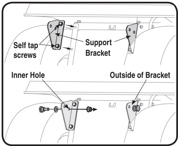
Figure 13
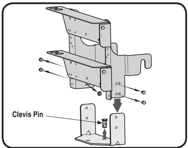
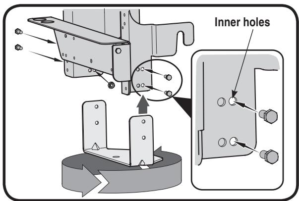
Figure 14
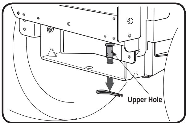
Figure 15
Figure 16
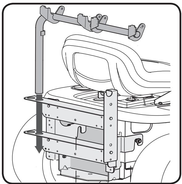
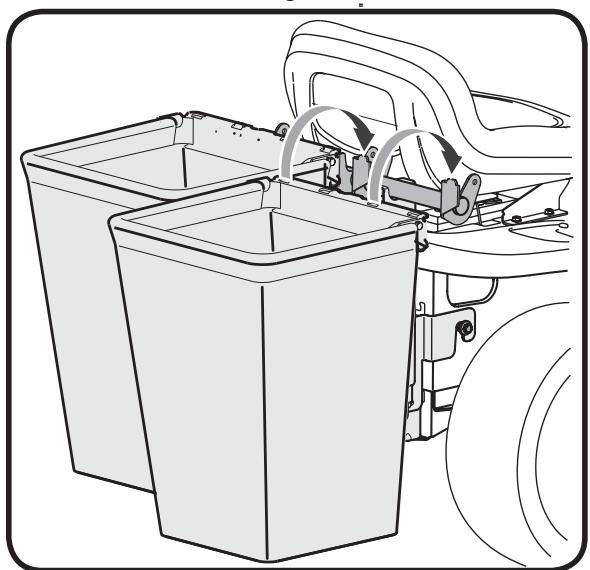
Figure 17
Figure 18
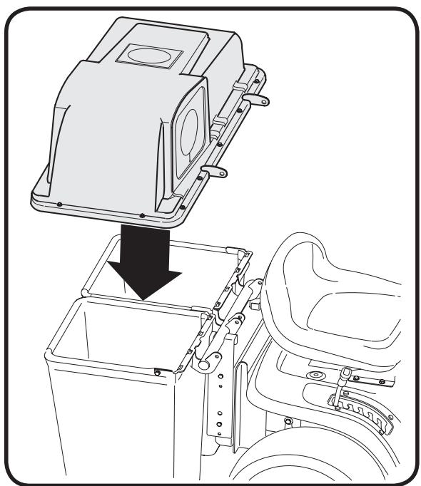
Figure 19
Attaching Grass Bags & Grass Bag Cover
- Place the support tube in position on the rear of unit by sliding the support tube down through the holes in the left side of the bracket assembly. Use the inside hole on the bracket assembly regardless of what size deck your tractor is equipped with. Refer to Figure 17.
- Attach the grass bags by hooking them onto the grass bag bracket using the slots in the grass bag and the tabs on the grass bag bracket as shown in Figure 18.
- Place the grass bag cover on top of the grass bags and align the holes on the hinges of the grass bag cover with the corresponding holes on the support tube assembly. See Figure 19.
- Insert the clevis pin through the hinge on the support tube assembly and then through the grass bag cover. See Figure 20.
- Secure with belleville washer and hairpin clip with the crown side of the washer going against the hairpin clip. See inset images in Figure 20.
- Repeat with the second set of hardware through the second hinge of the grass bag and the tube assembly from the opposite direction.
NOTE: Insert the clevis pins from the outside in as shown in the inset images of Figure 20.
NOTE: It is very important to maintain this order and direction while installing these hardware pieces. After installation, make sure that the grass bag cover pivots on the support tube and opens.
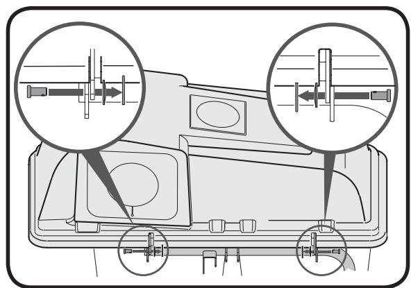
Figure 20

Attaching
Grass Bags
& Grass Bag
Cover
All Model Series
600 through 700

NOTE:
Insert the clevis pins from the outside in as shown in the inset images of Figure 20.
NOTE:
It is very important to maintain this order and direction while installing these hardware pieces. After installation, make sure that the grass bag cover pivots on the support tube and opens.

Attaching Discharge Chute
All 600 Model Series 600 through 699

NOTE:
The retainer strap is fitted at position A on the discharge chute. However, on older models of tractors, you will have to change the position of the strap depending on the location of the grass catcher pin on the deck. Remove the retainer strap from position A on the discharge chute to position B or C corresponding to the position of the grass catcher pin at A, B or C on the deck. See Figure 23.
Attaching Discharge Chute
On Older Model Riders
- On some older models, a clip is already installed on the cutting deck next to the discharge chute opening in position A, B, or C, as seen in Figure 21. If this is the case, the clip must be removed and a grass catcher pin installed.
- Pin Installation: A grass catcher pin (G in Figure 4) and nut (H in Figure 4) have been supplied in the hardware pack. First remove the clip, as seen in Figure 22A, by removing the nut and bolt. Then attach the grass catcher pin as seen in Figure 22B. Make sure to secure the pin tightly.
- Some units may not have clip, but will have an open hole for pin installation. In this case, install the grass catcher pin from the hardware pack in the available hole.
- You will then need to position the retainer strap on the discharge chute to correspond with the hole and pin. See Figure 23 for retainer strap positioning.
NOTE: The retainer strap is fitted at position A on the discharge chute. However, on older models of tractors, you will have to change the position of the strap depending on the location of the grass catcher pin on the deck. Remove the retainer strap from position A on the discharge chute to position B or C corresponding to the position of the grass catcher pin at A, B or C on the deck. See Figure 23.
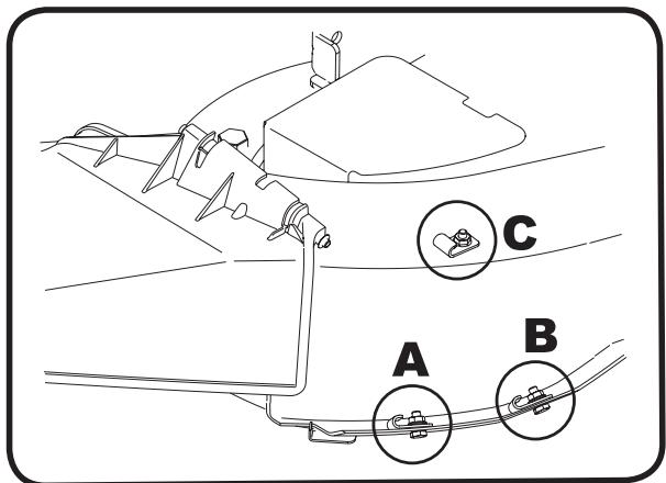
Figure 21
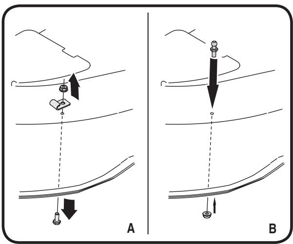
Figure 22
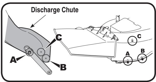
Figure 23
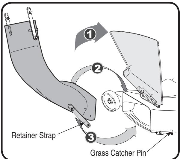
Figure 24
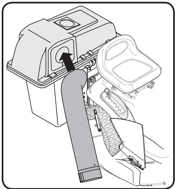
Figure 25
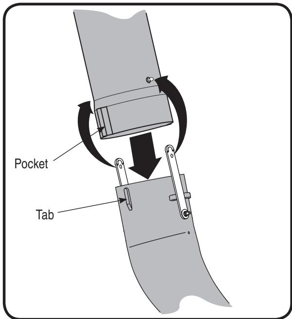
Figure 26
Attaching Discharge Chute
All Model Series
- Raise the deck to its highest position.
- Raise the chute deflector on the deck and hold it while you position the discharge chute over the chute opening.
- Place the top rear edge of the discharge chute over the top rear edge of the chute opening.
- Push down on the discharge chute so that its front bottom edge rolls around the bottom of the deck, then slide the chute forward to the stop on the deck. See Figure 24.
- Lock the discharge chute in position by hooking the retainer strap over the grass catcher pin on the deck. See Figure 24.
- Insert the curved end of chute tube into the hole in the grass bag cover. See Figure 25.
- Place the lower end of the chute tube over the discharge chute so that the tabs on the discharge chute fits into the pockets on the chute tube. See Figure 26.
- Secure by hooking the two retainer straps of the discharge chute to the pins on the chute tube. See Figure 26.
Bagger Usage
All Models - 600 through 700
NOTE: When both grass bags are full, place the tractor on a firm, level surface, disengage the PTO, turn the tractor engine off and set the parking brake.
- Flip Seat up.
- Lift up grass bag cover. Do not remove the chute tube assembly from the tractor.
- Remove the grass bags by lifting these up and moving the bags away from the support tube assembly.
- Empty the grass clippings at a proper disposal sight, use the handle at the bottom of each grass bag. Holding the bag firmly, empty the contents
- Replace grass bags, close lid, flip down seat, restart your tractor and resume cutting your grass.

Part List: Rear Twin Bagger

For parts and/or accessories please call 1-800-800-7310, or 1-330-220-4683.
www.mtdproducts.com
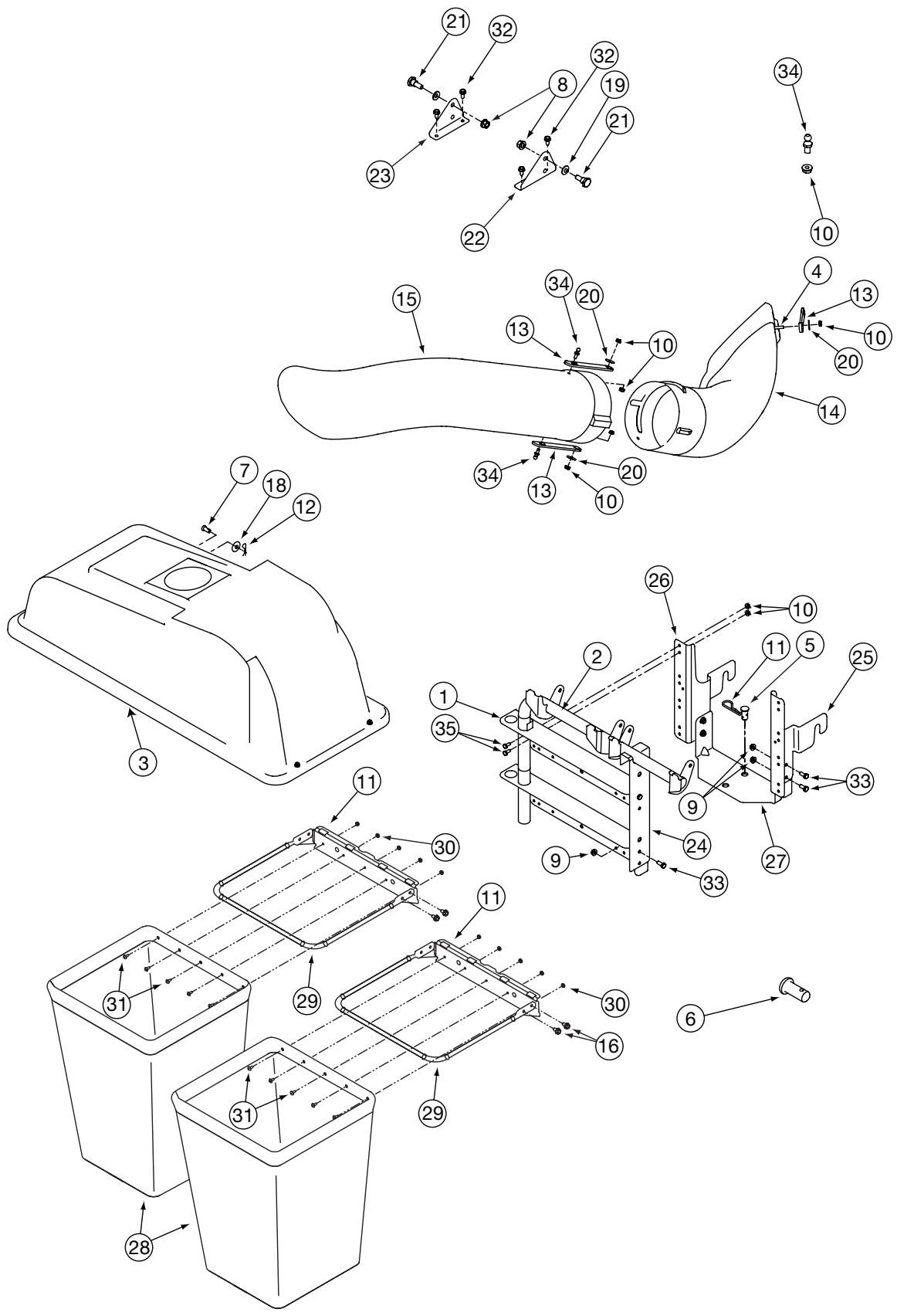
| REF NO. | PART NUMBER | DESCRIPTION | Qty. |
| 1 | 16587D | Support Bracket: Bagger | 1 |
| 2 | 16592 | Support Tube Assembly | 1 |
| 3 | 664-04017 | Grass catcher Cover Assembly | 1 |
| 4 | 710-0597 | Screw 1/4-20 x 1" | 3 |
| 5 | 711-0309A | Clevis Pin | 1 |
| 6 | 711-0310 | Clevis Pin (on older model tractors) | 1 |
| 7 | 711-1421 | Clevis Pin | 2 |
| 8 | 712-0459 | Lock Nut 7/16-20 | 2 |
| 9 | 712-3004A | Lock Nut 5/16-18 | 6 |
| 10 | 712-3027 | Hex Flange Lock Nut, 1/4-20 | 14 |
| 11 | 714-0117 | Hairpin Clip | 1 |
| 12 | 714-0145 | Click Pin | 2 |
| 13 | 723-04008A | Chute Strap | 3 |
| 14 | 731-04153 | Discharge Chute 38"/42" Bag | 1 |
| 15 | 731-0899E | Chute Tube | 1 |
| 16 | 710-0604A | Self-Tapping Screw 5/16-18 | 8 |
| 17 | 16591A | Bag Hanger Bracket | 2 |
| 18 | 736-0331 | Bell Washer | 2 |
| 19 | 736-0407 | Bell Washer | 2 |
| 20 | 736-3092 | Flat Washer | 3 |
| 21 | 738-1020 | Shoulder Screw | 2 |
| 22 | 783-04132A | Supt. Bracket RH | 1 |
| 23 | 783-04137A | Supt. Bracket LH | 1 |
| 24 | 783-0601 | Mounting Bracket | 1 |
| 25 | 783-0673A | Mounting Bracket RH | 1 |
| 26 | 783-0764A | Mounting Bracket LH | 1 |
| 27 | 783-0765 | Bracket: Cross Support | 1 |
| 28 | 764-0221 | Catcher Bag | 2 |
| 29 | 749-0701A | Grass Bag Frame | 2 |
| 30 | 712-0272 | Hex Sems Nut, #10-24 | 10 |
| 31 | 710-0473 | Machine Screw, , #10-24 x .5 | 10 |
| 32 | 710-0726 | AB Screw 5/16-12 | 4 |
| 33 | 710-3008 | Hex Head Screw 5/16-18 x .75 | 6 |
| 34 | 711-04069 | Grass Catcher Pin 1/4-20 | 3 |
| 35 | 710-0751 | Hex Head Screw 1/4-20 x .62 | 8 |

Part List: Rear Twin Bagger

For parts and/or accessories please call 1-800-800-7310, or 1-330-220-4683.
www.mtdproducts.com
MANUFACTURER'S LIMITED WARRANTY FOR

The limited warranty set forth below is given by MTD LLC with respect to new merchandise purchased and used in the United States, its possessions and territories.
"MTD" warrants this product against defects in material and workmanship for a period of two (2) years commencing on the date of original purchase and will, at its option, repair or replace, free of charge, any part found to be defective in materials or workmanship. This limited warranty shall only apply if this product has been operated and maintained in accordance with the Operator's Manual furnished with the product, and has not been subject to misuse, abuse, commercial use, neglect, accident, improper maintenance, alteration, vandalism, theft, fire, water, or damage because of other peril or natural disaster. Damage resulting from the installation or use of any part, accessory or attachment not approved by MTD for use with the product(s) covered by this manual will void your warranty as to any resulting damage.
Normal wear parts are warranted to be free from defects in material and workmanship for a period of thirty (30) days from the date of purchase. Normal wear parts include, but are not limited to items such as: batteries, belts, blades, blade adapters, grass bags, rider deck wheels, seats, snow thrower skid shoes, shave plates, auger spiral rubber and tires.
HOW TO OBTAIN SERVICE: Warranty service is available, WITH PROOF OF PURCHASE, through your local authorized service dealer. To locate the dealer in your area, check your Yellow Pages, or contact MTD LLC at P.O. Box 361131, Cleveland, Ohio 44136-0019, or call 1-800-800-7310 or 1-330-220-4683 or log on to our Web site at www.mtdproducts.com.
This limited warranty does not provide coverage in the following cases:
a. The engine or component parts thereof. These items may carry a separate manufacturer's warranty. Refer to applicable manufacturer's warranty for terms and conditions.
b. Log splitter pumps, valves, and cylinders have a separate one year warranty.
c. Routine maintenance items such as lubricants, filters, blade sharpening, tune-ups, brake adjustments, clutch adjustments, deck adjustments, and normal deterioration of the exterior finish due to use or exposure.
d. Service completed by someone other than an authorized service dealer.
e. MTD does not extend any warranty for products sold or exported outside of the United States, its possessions and territories, except those sold through MTD's authorized channels of export distribution.
f. Replacement parts that are not genuine MTD parts.
g. Transportation charges and service calls.
No implied warranty, including any implied warranty of merchantability of fitness for a particular purpose, applies after the applicable period of express written warranty above as to the parts as identified. No other express warranty, whether written or oral, except as mentioned above, given by any person or entity, including a dealer or retailer, with respect to any product, shall bind MTD. During the period of the warranty, the exclusive remedy is repair or replacement of the product as set forth above.
The provisions as set forth in this warranty provide the sole and exclusive remedy arising from the sale. MTD shall not be liable for incidental or consequential loss or damage including, without limitation, expenses incurred for substitute or replacement lawn care services or for rental expenses to temporarily replace a warranted product.
Some states do not allow the exclusion or limitation of incidental or consequential damages, or limitations on how long an implied warranty lasts, so the above exclusions or limitations may not apply to you. In no event shall recovery of any kind be greater than the amount of the purchase price of the product sold. Alteration of safety features of the product shall void this warranty. You assume the risk and liability for loss, damage, or injury to you and your property and/or to others and their property arising out of the misuse or inability to use the product. This limited warranty shall not extend to anyone other than the original purchaser or to the person for whom it was purchased as a gift.
HOW STATE LAW RELATES TO THIS WARRANTY: This limited warranty gives you specific legal rights, and you may also have other rights which vary from state to state.
IMPORTANT: Owner must present Original Proof of Purchase to obtain warranty coverage.
MANUAL DEL OPERADOR
Modelos series 600 a 619 inclusive

IMPORTANT:
Modelos series 600 a 619 inclusive
Modelos series 650 a 699 inclusive
Modelos series 650 a 699 inclusive
Modelos series 650 a 699 inclusive

IMPORTANT:
The provisions as set forth in this warranty provide the sole and exclusive remedy arising from the sale. MTD shall not be liable for incidental or consequential loss or damage including, without limitation, expenses incurred for substitute or replacement lawn care services or for rental expenses to temporarily replace a warranted product.
Montage dupalier support et dusupport defixation
Modèles de série
650 à 699

IMPORTANT:
Montage dupalier support et dusupport defixation
- TWIN REAR BAGGER KIT
- MODELS OHD-190-180
- IMPORTANT
- THIS OPERATOR'S MANUAL IS AN IMPORTANT PART OF YOUR NEW GRASS COLLECTOR. IT WILL HELP YOU ASSEMBLE, PREPARE AND MAINTAIN THE UNIT FOR BEST PERFORMANCE. PLEASE READ AND UNDERSTAND WHAT IT SAYS
- TABLE OF CONTENTS
- FINDING AND RECORDING MODEL NUMBER
- BEFORE YOU START ASSEMBLING YOUR NEW EQUIPMENT
- CUSTOMER SUPPORT
- PLEASE DO NOT RETURN THE UNIT TO THE RETAILER FROM WHICH IT WAS PURCHASED, WITHOUT FIRST CONTACTING CUSTOMER SUPPORT
- FASTATTACH™ TWIN BAG GRASS COLLECTOR
- DETERMINE THE MODEL OF YOUR RIDER
- RIDER MODEL IDENTIFICATION
- NOTE
- CONTENTS OF CARTON
- CONTENTS OF HARDWARE PACK
- FOR ALL MODEL SERIES 650 THROUGH 699 TRACTORS
- FOR ALL MODEL SERIES 700 TRACTORS
- FOR OLDER TRACTORS ONLY
- FOR DECKS WITH GRASS CATCHER PIN NOT PRE-INSTALLED
- ATTACHING BRACKET ASSEMBLY
- ATTACHING THE BRACKET ASSEMBLY
- MODEL SERIES 600 THROUGH 619
- MODEL SERIES 650 THROUGH 699
- ASSEMBLING SUPPORT BRACKETS
- ATTACHING SUPPORT BRACKET & BRACKET ASSEMBLY
- MODEL SERIES 700
- ATTACHING GRASS BAGS & GRASS BAG COVER
- ATTACHING
- GRASS BAGS
- GRASS BAG
- COVER
- ALL MODEL SERIES
- 600 THROUGH 700
- ATTACHING DISCHARGE CHUTE
- ON OLDER MODEL RIDERS
- BAGGER USAGE
- ALL MODELS - 600 THROUGH 700
- PART LIST: REAR TWIN BAGGER
- MANUFACTURER'S LIMITED WARRANTY FOR
- MANUAL DEL OPERADOR
- MODELOS SERIES 600 A 619 INCLUSIVE
- MODELOS SERIES 650 A 699 INCLUSIVE
- MONTAGE DUPALIER SUPPORT ET DUSUPPORT DEFIXATION
Brand : MTD
Model : OHD-190-180
Category : Lawn mower