
BV3100 - Leaf blower MTD - Free user manual and instructions
Find the device manual for free BV3100 MTD in PDF.
User questions about BV3100 MTD
0 question about this device. Answer the ones you know or ask your own.
Ask a new question about this device
Download the instructions for your Leaf blower in PDF format for free! Find your manual BV3100 - MTD and take your electronic device back in hand. On this page are published all the documents necessary for the use of your device. BV3100 by MTD.
USER MANUAL BV3100 MTD
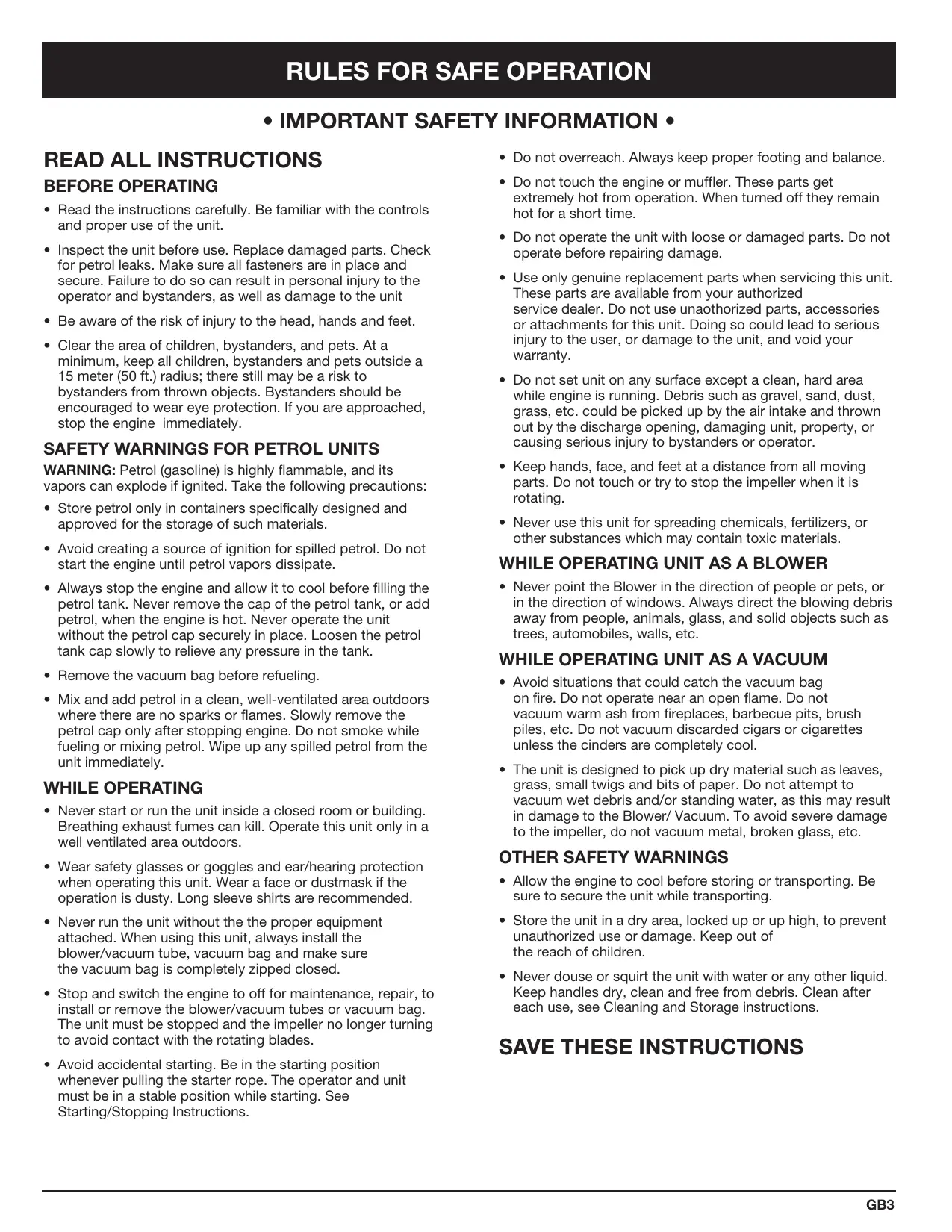
2-Cycle Mulching Blower Vacuum


GB • OPERATOR'S MANUAL . . . . . . . . . . . . . . . . . .
F MANUEL D'UTILISATION .F1
D ·BENUTZERHANDBUCH D1
MANUALE D'ISTRUZIONI PER L'USO...11
P·MANUAL DE UTILIZACHO 1
E·MANUAL DE INSTRUCCIONES...E1


INTRODUCTION
BV3100
2-Cycle Mulching Blower Vacuum
IMPORTANT MANUAL
DO NOT THROW AWAY
THANK YOU
Thank you for buying this quality product. Read the whole manual and follow all the instructions to keep your new outdoor power tool in top operating condition.
NOTE: PROOF OF PURCHASE WILL BE REQUIRED FOR WARRANTY SERVICE.
Make sure this manual is carefully read and understood before starting or operating this equipment.
TABLE OF CONTENTS
I. Rules for Safe Operation GB3 - GB5
A. Important Safety Information GB3
B. Safety and International Symbols . . . . . . . . . . . . . . . . . . . . . . . . . . . . . . . . . . .
C.Know Your Unit . GB5
II. Assembly Instructions GB5 - GB7
A. Attaching and Removing the Blower/Vacuum Tube . . . GB5
B. Attaching and Removing the Vacuum Bag . . . . . . . . . . . . . . . . . . . . . . . . . . . . . . . . . . .
C. Installing and Adjusting the Shoulder Harness . . . GB7
III. Oil and Petrol Information GB7
IV. Starting/Stopping Instructions GB8
V. Operating Instructions GB9 - GB10
A. Holding the Blower / Vacuum . . . . . . . . . . . . . . . . . . . . . . . . . . . . . . . . . . . . . . . . . . . . . . . . . . .
B. Operating Tips GB9
C. Operating as a Blower GB9
D. Operating as a Vacuum . GB10
E. Clearing aBlocked Tube/Impeller . GB10
F. Empty the Vacuum Bag GB10
VI. Maintenance and Repair Instructions . . . . GB10 - GB12
A. Air Filter Maintenance . GB11
B. Replacing the Spark Plug GB12
VII. Cleaning and Storage GB12
VIII. Troubleshooting Chart GB13
IX. Specifications. GB14
CONTENTS OF CARTON
This unit includes the following:
- Model BV3100 Mulching Blower Vacuum
- Blower/Vacuum Tube
Shoulder Harness
Vacuum bag - Hardware Pack
Operator's Manual
The purpose of safety symbols is to attract your attention to possible dangers. The safety symbols, and their explanations, deserve your careful attention and understanding. The safety warnings do not by themselves eliminate any danger. The instructions or warnings they give are not substitutes for proper accident prevention measures.
SYMBOL MEANING

SAFETY ALERT SYMBOL: Indicates danger, warning, or caution. Attention is required in order to avoid serious personal injury. May be used in conjunction with other symbols or pictographs.
NOTE: Advises you of information or instructions vital to the operation or maintenance of the equipment.

CAUTION: Failure to obey a safety warning may result in property damage or personal injury to yourself or to others. Always follow the safety precautions to reduce the risk of fire, electric shock, and personal injury.
- Read the instructions carefully. Be familiar with the controls and proper use of the unit.
- Inspect the unit before use. Replace damaged parts. Check for petrol leaks. Make sure all fasteners are in place and secure. Failure to do so can result in personal injury to the operator and bystanders, as well as damage to the unit
- Be aware of the risk of injury to the head, hands and feet.
- Clear the area of children, bystanders, and pets. At a minimum, keep all children, bystanders and pets outside a 15 meter (50 ft.) radius; there still may be a risk to bystanders from thrown objects. Bystanders should be encouraged to wear eye protection. If you are approached, stop the engine immediately.
SAFETY WARNINGS FOR PETROL UNITS
WARNING: Petrol (gasoline) is highly flammable, and its vapors can explode if ignited. Take the following precautions:
- Store petrol only in containers specifically designed and approved for the storage of such materials.
- Avoid creating a source of ignition for spilled petrol. Do not start the engine until petrol vapors dissipate.
- Always stop the engine and allow it to cool before filling the petrol tank. Never remove the cap of the petrol tank, or add petrol, when the engine is hot. Never operate the unit without the petrol cap securely in place. Loosen the petrol tank cap slowly to relieve any pressure in the tank.
- Remove the vacuum bag before refueling.
- Mix and add petrol in a clean, well-ventilated area outdoors where there are no sparks or flames. Slowly remove the petrol cap only after stopping engine. Do not smoke while fueling or mixing petrol. Wipe up any spilled petrol from the unit immediately.
WHILE OPERATING
- Never start or run the unit inside a closed room or building. Breathing exhaust fumes can kill. Operate this unit only in a well ventilated area outdoors.
- Wear safety glasses or goggles and ear/hearing protection when operating this unit. Wear a face or dustmask if the operation is dusty. Long sleeve shirts are recommended.
- Never run the unit without the proper equipment attached. When using this unit, always install the blower/vacuum tube, vacuum bag and make sure the vacuum bag is completely zipped closed.
- Stop and switch the engine to off for maintenance, repair, to install or remove the blower/vacuum tubes or vacuum bag. The unit must be stopped and the impeller no longer turning to avoid contact with the rotating blades.
-
Avoid accidental starting. Be in the starting position whenever pulling the starter rope. The operator and unit must be in a stable position while starting. See Starting/Stopping Instructions.
-
Do not overreach. Always keep proper footing and balance.
- Do not touch the engine or muffler. These parts get extremely hot from operation. When turned off they remain hot for a short time.
- Do not operate the unit with loose or damaged parts. Do not operate before repairing damage.
- Use only genuine replacement parts when servicing this unit. These parts are available from your authorized service dealer. Do not use unauthorized parts, accessories or attachments for this unit. Doing so could lead to serious injury to the user, or damage to the unit, and void your warranty.
- Do not set unit on any surface except a clean, hard area while engine is running. Debris such as gravel, sand, dust, grass, etc. could be picked up by the air intake and thrown out by the discharge opening, damaging unit, property, or causing serious injury to bystanders or operator.
- Keep hands, face, and feet at a distance from all moving parts. Do not touch or try to stop the impeller when it is rotating.
- Never use this unit for spreading chemicals, fertilizers, or other substances which may contain toxic materials.
- Never point the Blower in the direction of people or pets, or in the direction of windows. Always direct the blowing debris away from people, animals, glass, and solid objects such as trees, automobiles, walls, etc.
- Avoid situations that could catch the vacuum bag on fire. Do not operate near an open flame. Do not vacuum warm ash from fireplaces, barbecue pits, brush piles, etc. Do not vacuum discarded cigars or cigarettes unless the cinders are completely cool.
- The unit is designed to pick up dry material such as leaves, grass, small twigs and bits of paper. Do not attempt to vacuum wet debris and/or standing water, as this may result in damage to the Blower/ Vacuum. To avoid severe damage to the impeller, do not vacuum metal, broken glass, etc.
OTHER SAFETY WARNINGS
- Allow the engine to cool before storing or transporting. Be sure to secure the unit while transporting.
- Store the unit in a dry area, locked up or up high, to prevent unauthorized use or damage. Keep out of the reach of children.
- Never douse or squirt the unit with water or any other liquid. Keep handles dry, clean and free from debris. Clean after each use, see Cleaning and Storage instructions.
SAVE THESE INSTRUCTIONS
SAFETY AND INTERNATIONAL SYMBOLS
This operator's manual describes safety and international symbols and pictographs that may appear on this product. Read the operator's manual for complete safety, assembly, operating and maintenance and repair information.

SYMBOL
MEANING
- SAFETY ALERT SYMBOL
Indicates danger, warning, or caution. May be used in conjunction with other symbols or pictographs.

WARNING - READ OPERATOR'S MANUAL
Read the Operator's Manual(s) and follow all warnings and safety instructions. Failure to do so can result in serious injury to the operator and/or bystanders.

- WEAR EYE AND HEARING PROTECTION
WARNING: Thrown objects and loud noise can cause severe eye injury and hearing loss. Wear eye protection meeting ANSI Z87.1-1989 standards and ear protection when operating this unit. Use a full face shield when needed.

- KEEP BYSTANDERS AWAY
WARNING: Keep all bystanders, especially children and pets, at least 15 meters (50 ft.) from the operating area.

- PRIMER
Push primer bulb, fully and slowly, 10 times.

- UNLEADED PETROL
Always use clean, fresh unleaded petrol.

OIL
Refer to operator's manual for the proper type of oil.

- THROWN OBJECTS CAN CAUSE SEVERE INJURY
WARNING: Keep clear of blower outlet. Never point the blower at yourself or others. Objects can be thrown from blower. Do not operate unit without proper attachments and guards in place.
SYMBOL

MEANING
- IGNITION SWITCH ON / START / RUN

- IGNITION SWITCH OFF or STOP

- HOT SURFACE WARNING
Do not touch a hot muffler or cylinder. You may get burned. These parts get extremely hot from operation. When turned off they remain hot for a short time.

- CHOKE CONTROL
1 • FULL choke position.
2·PARTIAL choke position.
3·RUN position.

- BLOWERS AND BLOWER/VACUUMS - ROTATING IMPELLER BLADES CAN CAUSE SEVERE INJURY
WARNING: Stop the engine and allow the impeller to stop before installing or changing tubes or bag, or before cleaning or performing any maintenance.

A

B
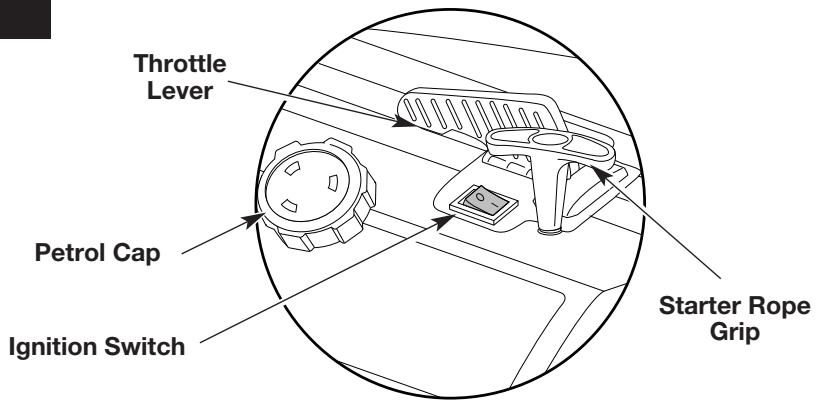
- BLOWER/VACUUM MODE CHANGE-OVER LEVER
A - Vacuum mode
B - Blower mode

- THROTTLE CONTROL
Indicates "HIGH" or "FASTEST" speed.

- THROTTLE CONTROL
Indicates "IDLE," "LOW" or "SLOWEST" speed.
- Cleaning of yards, garages, driveways, porches, patios, around walls, fences, etc.
As a vacuum
- Picking up leaves, light debris, etc.
ASSEMBLY INSTRUCTIONS
ATTACHING AND REMOVING THE BLOWER/ VACUUM TUBE
Attaching
NOTE: The blower/vacuum tube comes unassembled on this unit. Installation is required to provide safe and easy use for the operator.
- Remove the screws and nuts provided from the hardware pack.
-
Insert the blower/vacuum tube all the way into the opening on the motor housing until the holes in the tabs on the blower/vacuum tube align with the screw holes in the housing (Fig. 1).
-
Insert the 2 (two) 8 - 32 × 3 / 4 slotted T20 Torx screws into the right side of the motor housing and the 2 (two) nuts into the left side of the motor housing (Fig. 2).
- Tighten the screws firmly. Do not over-tighten.
- Install the 2 (two) remaining self-tapping 8 - 16 × 3 / 4 slotted T20 Torx screws into the holes on either side of the housing (Fig. 2). Tighten until snug, do not over-tighten.
ASSEMBLY INSTRUCTIONS
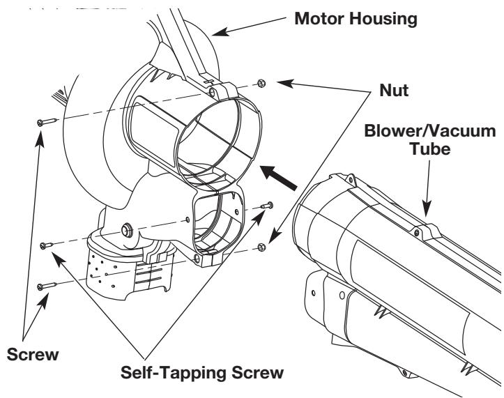
Fig. 1
Removing

WARNING: To prevent serious personal injury, stop the engine and allow the impeller to stop before attaching or removing tubes.
- Remove the 2 (two) self-tapping screws from either side of the housing.
- Remove the 2 (two) screws and nuts holding the blower/vacuum tube on the housing (Fig. 1).
NOTE: Keep the hardware in a safe place for future use.
- Remove the blower/vacuum tube from the motor housing.
- Replace the blower/vacuum tube before use.
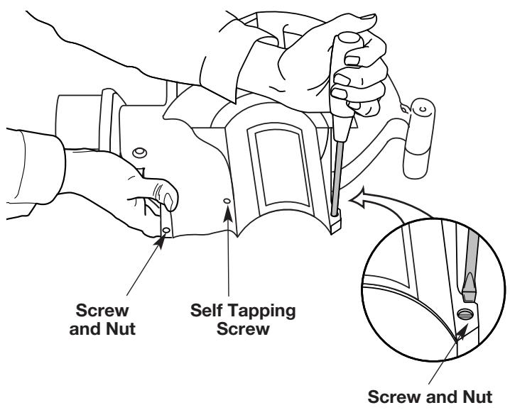
Fig. 2
ATTACHING AND REMOVING THE VACUUM BAG Attaching
- Attach the vacuum bag to the vacuum bag hook on the blower/vacuum tube (Fig. 3).
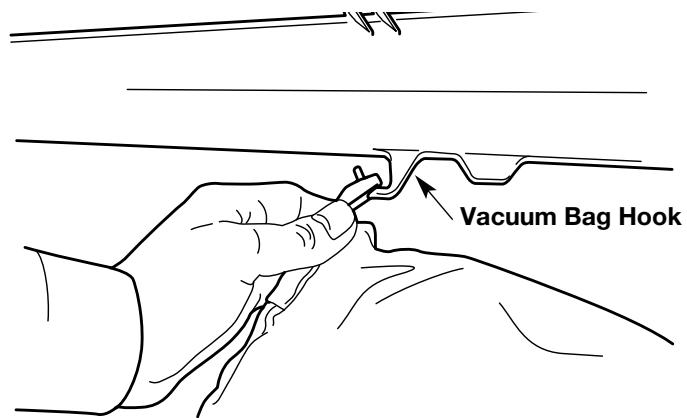
Fig. 3
- Slide the vacuum bag tube over the debris exhaust tube on the housing. Push the tube until the latching tabs on both sides click into place, securing the bag on the unit (Fig. 4).
Removing
- Press the latching tabs on both sides of the vacuum bag tube and pull the vacuum bag from the unit (Fig. 5).
- Detach the vacuum bag from the vacuum bag hook.
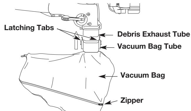
Fig. 4
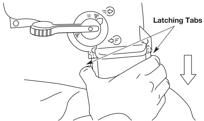
Fig. 5
ASSEMBLY INSTRUCTIONS
INSTALLING AND ADJUSTING THE SHOULDER HARNESS
NOTE: Have the shoulder harness on and adjusted (but not clipped to the support fitting) prior to starting unit.
- Push the strap through the center of the buckle.
- Pull the strap over the cross bar and down through the slot in the buckle (Fig. 6).
- Fully extend the harness.
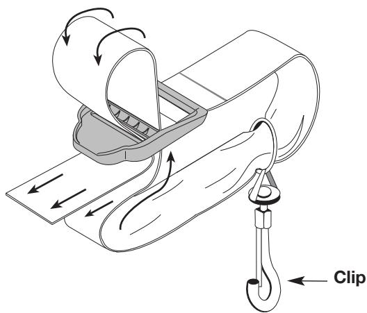
Fig. 6
- Attach the metal clip of the shoulder harness to either support fitting on top of the handle (Fig. 7).
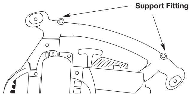
Fig. 7
- Place the harness over your head and onto your shoulder (Fig. 8).
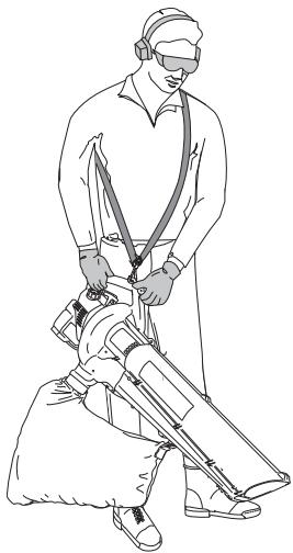
Fig. 8
- While standing in the operating position (Fig. 8) adjust length to fit the operator's size.
Lengthen the harness by pulling down on the strap and lifting the buckle end up (Fig. 9).
- Shorten the harness by pulling the strap back through the buckle while holding the buckle (Fig. 9).
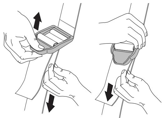
Fig. 9
OIL AND PETROL INFORMATION
Old and/or improperly mixed petrol are usually the main reasons for the unit not running properly. Be sure to use fresh, clean petrol and follow the instructions carefully for the proper petrol/oil mixture.
RECOMMENDED OIL TYPE
Use a high quality oil formulated for use in 2-cycle, air-cooled engines.
RECOMMENDED PETROL TYPE
Always use clean, fresh, unleaded petrol (gasoline) that is less than 60 days old.

WARNING: petrol (gasoline) is extremely flammable and its vapors can explode if they are ignited. Always stop the engine and allow it to cool before filling the petrol tank. Do not smoke while filling the tank. Keep sparks and open flames away from the area.
OIL AND PETROL MIXING INSTRUCTIONS
Thoroughly mix 5 liters of unleaded petrol (gasoline) with 125 ml. of 2 cycle engine oil in a separate petrol can (40:1). Do not mix them directly in the engine petrol tank.
STARTING/STOPPING INSTRUCTIONS
STARTING INSTRUCTIONS
- Mix petrol (gasoline) with oil. Fill petrol tank with petrol/oil mixture. See Oil and Petrol Mixing Instructions.

WARNING: To avoid serious personal injury, always remove the vacuum bag prior to refueling the unit. The bag may become a fire hazard when saturated with petrol.
NOTE: Before you start the unit, put on the shoulder harness and adjust it, but don't clip it to the support fitting.
NOTE: The throttle control will remain in the position it's placed until moved. Fast position is to the right. Also, there is no need to turn the unit on.
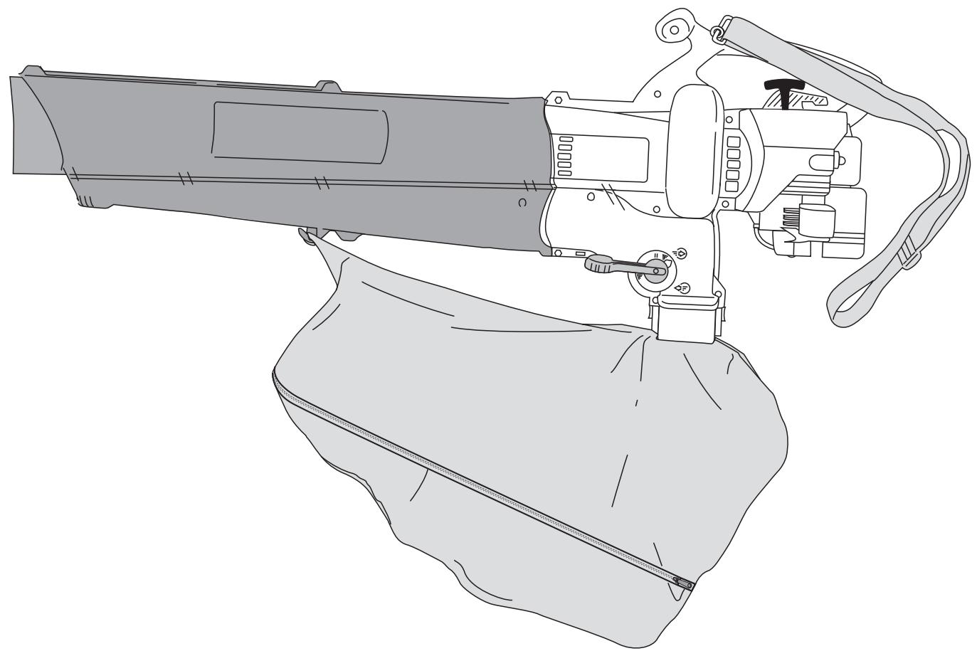
- Put the Ignition Switch in the ON (I) position.
- Set the blower/vacuum mode change-over lever to the up position (Blower Mode). See Operating as a Blower.
- Fully press and release primer bulb slowly 10 times. Petrol should be felt and visible in the bulb (Fig. 11). If petrol hasn't entered the bulb, press until it does.
- Place the choke lever in Position 1 (Fig. 11).
- With the unit on the ground, move the throttle lever to the fast position ( ) (Fig. 10).
- Pull the starter rope out with a controlled and steady motion 5 times (Fig. 12).
- Place the choke lever in Position 2 (Fig. 11).
- Pull the starter rope out with a controlled and steady motion 1 to 3 times to start the engine (Fig. 12).
NOTE: The unit uses Spring Assist Starting™, which significantly reduces the effort required to start the engine. You must pull the starter rope out far enough to hear the engine attempt to start. There is no need to pull the rope briskly-- there is no harsh resistance when pulling. Be aware that this starting method is vastly different from (and much easier than) what you may be used to.
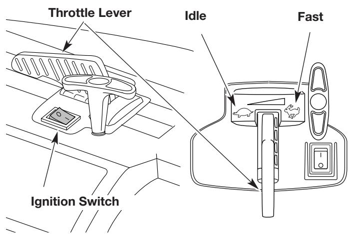
Fig. 10
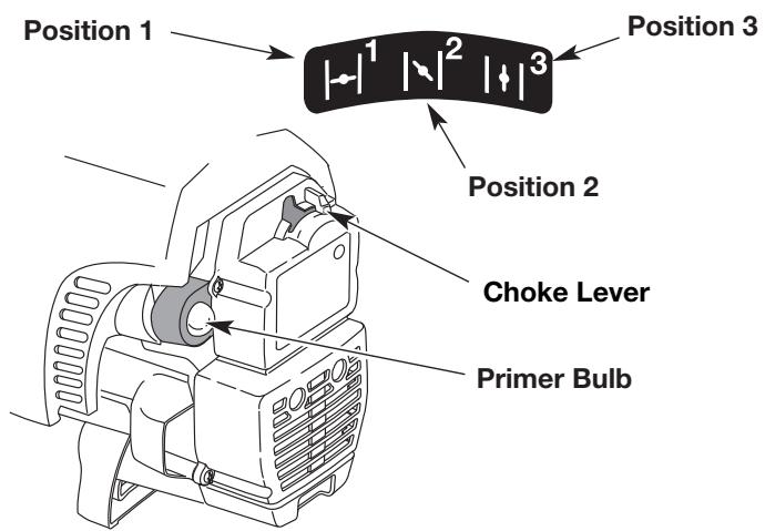
Fig. 11
- If the engine does not start, go back to step 4.
- Allow the engine to warm up for 5 to 10 seconds. Place the choke lever in Position 3 (Fig. 11).
- Stand in the operating position and clip the shoulder harness to the support fitting
NOTE: If you are having trouble starting the unit or are operating in extreme temperatures (below 40^ F, above 90^ F), refer to the Troubleshooting section.
STOPPING INSTRUCTIONS
- Move the throttle lever to the idle position (Fig. 10). Allow the engine to cool down by idling.
- Put the ignition switch down in the STOP [O] position (Fig. 10).
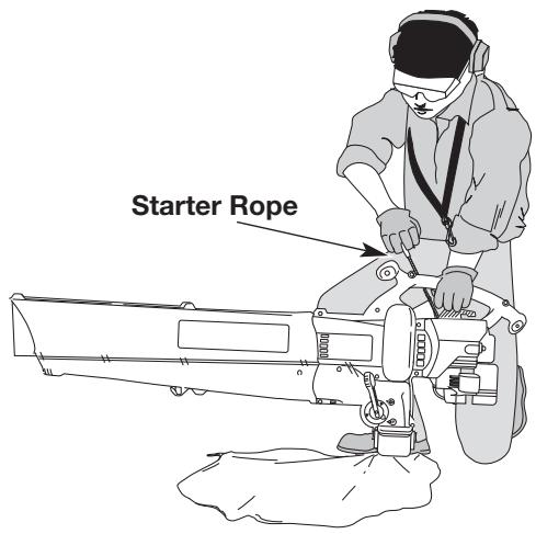
Fig. 12
OPERATING INSTRUCTIONS
HOLDING THE BLOWER/VACUUM
Before operating the unit, stand in the operating position (Fig. 13). Check for the following:
- Operator is wearing proper clothing, such as boots, safety glasses or goggles, ear/hearing protection, gloves, long pants and long sleeve shirt.
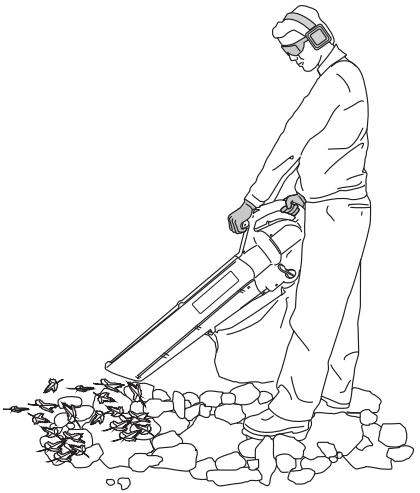
Fig. 13
OPERATING TIPS
- Be sure the vacuum bag is zipped closed before operating the unit.
Assure the unit is not directed at loose debris or persons before starting unit. - The unit is in good working condition. The tubes and guards are in place and secure.
- Always hold the unit with both hands when operating. Keep a firm grip on both the front and rear handle or grips.
- To reduce the risk of hearing loss associated with sound level(s), the use of hearing protection is required.
- Watch out for children, pets, open windows, or freshly washed cars, and blow debris away.
- After using blowers and other equipment, clean up. Dispose of debris in trash receptacles.
- Start engine. See Starting/Stopping Instructions.
- Set the blower/vacuum mode change-over lever to the up position (Blower Mode) (Fig. 14).
NOTE: Never use the unit with the lever in the halfway position.
3. Place the shoulder harness over your head and onto your shoulder and adjust properly, see Installing and Adjusting the Shoulder Harness.
Hold the blower as shown in Figures. 15, 16, and 17. Sweep from side to side with the nozzle several inches above the ground or floor. Slowly advance, keeping the accumulated pile of debris in front of you.
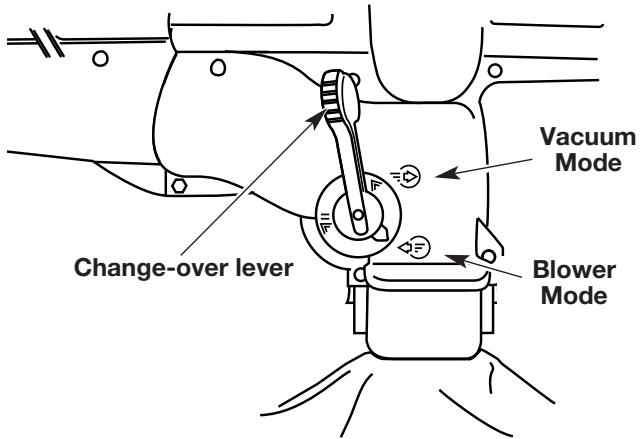
Fig. 14
Most dry blowing operations are better suited to low speed than high, while high speed is better for moving heavier items like large debris or gravel.
Use the blower for trees, shrubs, flower beds and hard to clean areas (Fig. 15).
Use the blower around buildings and for other normal cleaning (Fig. 16).
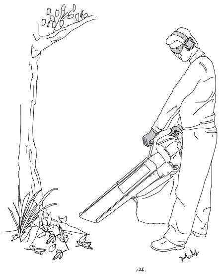
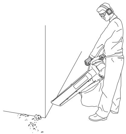
Fig. 15
Fig. 16
OPERATING INSTRUCTIONS
Use the blower for walls, overhangs and screens (Fig. 17).
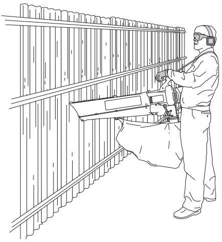
Fig. 17
- Start engine. See Starting/Stopping Instructions.
- Set the blower/vacuum mode change-over lever to the down position (Vacuum Mode) (Fig. 19).
NOTE: Never use the unit with the lever in the halfway position.
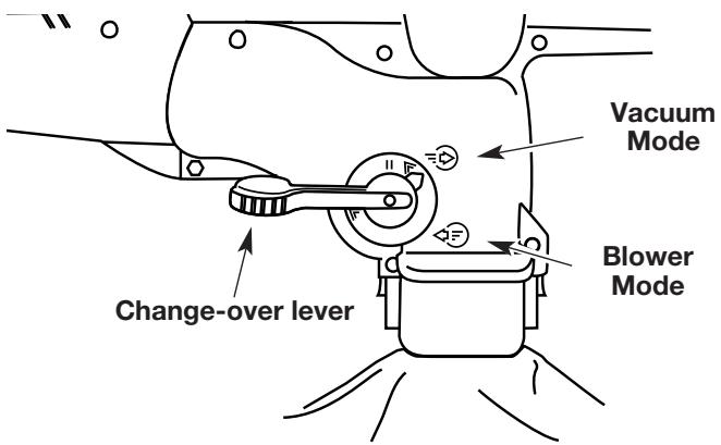
Fig. 18
- Place the shoulder harness over your head and onto your shoulder and adjust properly, see Installing and Adjusting the Shoulder Harness.
Hold the vacuum, tilting the blower/vacuum tube slightly, and use a sweeping action to collect light debris (Fig. 19). Small leaves and twigs will flow into the vacuum bag and be mulched as they pass through the fan housing, allowing the vacuum bag to hold more debris.
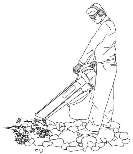
Fig. 19
EMPTYING THE VACUUM BAG
- While pressing the latching tabs on both sides of the vacuum bag tube, pull the vacuum bag off the unit (Fig. 20).
- Detach the vacuum bag from the vacuum bag hook.
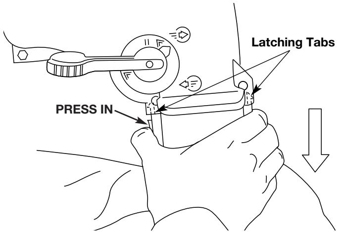
Fig. 20
- Unzip the bag and empty the contents into a garbage bag or container.
- Turn the bag inside out after initial emptying and vigorously shake out dust and debris.
- Turn Right-side out, Zip the bag closed and reinstall vacuum bag.
MAINTENANCE AND REPAIR INSTRUCTIONS
AIR FILTER MAINTENANCE
Removing the Air Filter/Muffler Cover
- Place the choke lever in Position 2.
NOTE: The choke lever must be in Position 2 (Fig. 21) to remove the air filter/muffler cover.
- Remove the four (4) screws securing the air filter/muffler cover (Fig. 21). Use a flat blade or T-20 Torx bit screwdriver.
- Pull the cover from the engine. Do not force.
Cleaning the Air Filter
Clean and re-oil the air filter every 10 hours of operation. It is an important item to maintain. Failure to maintain your air filter properly can result in poor performance or can cause permanent damage to your engine.
- Remove the air filter/muffler cover. See Removing the Air filter/Muffler Cover.
- Remove the air filter from behind the air filter/muffler cover (Fig. 22).
- Wash the filter in detergent and water (Fig. 23). Rinse the filter thoroughly. Squeeze out excess water. Allow it to dry completely.
- Apply enough clean oil to lightly coat the filter (Fig. 24).
- Squeeze the filter to spread and remove excess oil (Fig. 25).
- Replace the air filter in the air filter/muffler cover (Fig. 22).
NOTE: Operating the unit without the air filter and air filter/muffler cover assembly, will Void the warranty.
Reinstalling the Air Filter/Muffler Cover
- Place the air filter/muffler cover over the back of the carburetor and muffler.
NOTE: The choke lever must be in Position 2 (Fig. 21) to install the air filter/muffler cover.
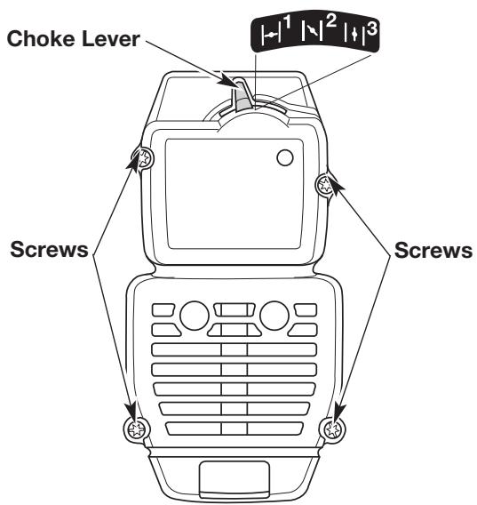
Fig. 21
- Insert the four (4) screws into the holes in the air filter/muffler cover (Fig. 21) and tighten. Use a flat blade or T-20 Torx bit screwdriver. Do not over tighten. Do not force.
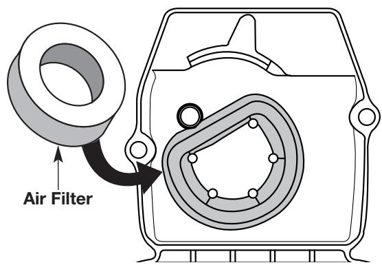
Fig. 22
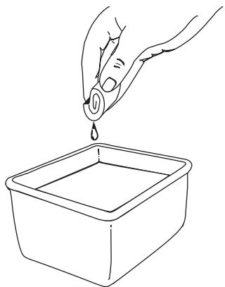
Fig. 23
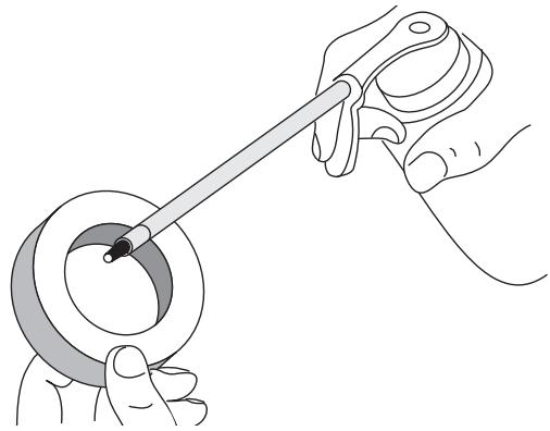
Fig. 24
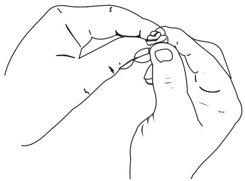
Fig. 25
MAINTENANCE AND REPAIR INSTRUCTIONS
REPLACING THE SPARK PLUG
Use a Champion RDJ7Y spark plug (or equivalent). The correct air gap is 0.5mm (0.020 in.). Remove the plug after every 25 hours of operation and check its condition.
- Stop the engine and allow it to cool. Grasp the plug wire firmly and pull the cap from the spark plug.
- Clean dirt from around the spark plug. Remove the spark plug from the cylinder head by turning a 5/8 in. socket counterclockwise.
-
Replace cracked, fouled or dirty spark plug. Set the air gap at 0.5mm (0.020 in.) using a feeler gauge (Fig. 26).
-
Install a correctly gapped spark plug in the cylinder head. Tighten by turning the 5/8 in. socket clockwise until snug.
If using a torque wrench, torque to;
12.3-13.5 N·m (110-120 in.·lb.).
Do not over tighten.
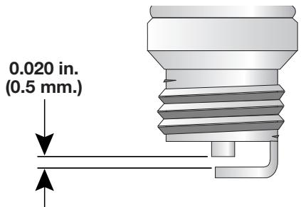
Fig. 26
CLEANING AND STORAGE
CLEANING THE UNIT
Use a small brush to clean off the outside of the unit and to keep the air vents free of obstructions.
CLEANING THE VACUUM BAG
- Empty the bag after each use to avoid deterioration and obstructing air flow, which will reduce the performance of the vacuum.
- Wearing eye protection and a dust mask, clean the bag as needed. Turn the bag inside out after initial emptying and vigorously shake out dust and debris.
- Wash the bag once a year or more often if needed:
a. Remove the vacuum bag.
b. Turn bag inside out.
c. Hang up.
d. Hose down thoroughly.
e. Hang to dry.
f. Turn bag right-side out and reinstall.
STORAGE
- Allow the engine to cool before storing.
- Store the unit locked up to prevent unauthorized use or damage.
- Store the unit in a dry, well ventilated area.
- Store the unit out of the reach of children.
LONG TERM STORAGE
If the unit will be stored for an extended time,
- Drain all petrol from the petrol tank into a container. Do not use petrol that has been stored for more than 60 days. Dispose of the old petrol in accordance to local regulations.
- Start the engine and allow it to run until it stalls. This ensures that all petrol has been drained from the carburettor.
- Allow the engine to cool. Remove the spark plug and put 30ml (1 oz.) of high quality motor oil into the cylinder. Pull the starter rope slowly to distribute the oil. Reinstall the spark plug.
NOTE: Remove the spark plug and drain all of the oil from the cylinder before attempting to start the blower/vacuum after storage.
4. Thoroughly clean the unit and inspect for any loose or damaged parts. Repair or replace damaged parts and tighten loose screws, nuts or bolts. The unit is ready for storage.
TRANSPORTING
- Allow the engine to cool before transporting.
- Secure the unit while transporting.
- Drain the petrol tank before transporting.
- Tighten petrol cap before transporting.
TROUBLESHOOTING
ENGINE WILL NOT START
CAUSE
The ignition switch is in the OFF (0) position
Empty petrol tank
Primer bulb wasn't pressed enough.
Engine flooded
Old or improperly mixed petrol
Fouled spark plug
Plugged spark arrestor
The outside temperature is below 40^ F
The outside temperature is above 90^ F
ENGINE WILL NOT IDLE
CAUSE
Air filter is plugged
Old or improperly mixed petrol
Improper carburetor adjustment
ENGINE WILL NOT ACCELERATE
CAUSE
Old or improperly mixed petrol
Improper carburetor adjustment
ENGINE LACKS POWER OR STALLS WHEN UNDER LOAD
CAUSE
Old or improperly mixed petrol
Improper carburetor adjustment
UNIT WILL NOT BLOW OR VACUUM
CAUSE
Bag is full
Damaged impeller
ACTION
Put the switch in the ON (I) position
Fill petrol tank
Press primer bulb fully and slowly 10 times
Flip throttle level to FAST and pull starter rope
Drain petrol tank / Add fresh petrol mixture
Replace or clean the spark plug
Clean or replace spark arrestor
Pull the starter rope up to 10-15 times
Put the throttle control in Fast and pull the starter rope
ACTION
Replace or clean the air filter
Drain petrol tank / Add fresh petrol mixture
Take to an authorized service dealer for carburetor adjustment
ACTION
Drain petrol tank / Add fresh petrol mixture
Take to an authorized service dealer for carburetor adjustment
ACTION
Drain petrol tank / Add fresh petrol mixture
Take to an authorized service dealer for carburetor adjustment
ACTION
Empty Bag. See Empty the Vacuum Bag
Take unit to an authorized service dealer
SPECIFICATIONS
ENGINE
| Engine Type | Air-Cooled, 2-Cycle |
| Displacement | 31 cm³ (1.9 cu. in.) |
| Maximum Engine Performance in accordance with ISO 8893 | 0.75 kw (1 hp) |
| Operating RPM (@ 300 rd) | Vac: 6,800+ Blow: 7,200+ rpm |
| Idle Speed RPM (@ 300 rd) | 3,600 - 4,200 rpm |
| Ignition Type | Electronic |
| Ignition Switch | Rocker Switch |
| Spark Plug Gap | 0.5 mm (0.020 in.) |
| Lubrication | Petrol/Oil Mixture |
| Petrol/Oil Ratio | 40:1 |
| Carburettor | Diaphragm, All-Position |
| Starter | Auto Rewind |
| Muffler | Baffled with Guard |
| Throttle | Manual |
| Petrol Tank Capacity | 385 ml (13 oz.) |
BLOWER / VACUUM
| Throttle Control | Finger-Tip Lever |
| Blower Velocity | up to 290 kmh (180 mph) |
| Blower Air Output | up to 12.1 cmm (424 cfm) |
| Mulching Ratio | up to 10:1 |
| Vacuum Bag Capacity | 35.24 Liters (1.0 bushels) |
| Shoulder Harness | Single Quick-Snap |
| Approximate Mass (no petrol, with blower/vacuum tube and empty vacuum bag) | 6 kg (13.5 lb.) |
| Front Vibration Level (Idle)* | 4.77 m/s2 |
| Rear Vibration Level (Idle)* | 5.85 m/s2 |
| Front Vibration Level (Operating RPM)* | 8.61 m/s2 |
| Rear Vibration Level (Operating RPM)* | 10.46 m/s2 |
| Sound Pressure Level (Idle) † | 76 LpeqdB(A) |
| Sound Power Level (Idle) ‡ | 96 LweqdB(A) |
| Sound Pressure Level (Operating RPM) † | 89 LpeqdB(A) |
| Sound Power Level (Operating RPM) ‡ | 109 LweqdB(A) |
- Method for obtaining level per ISO 7916 † Method for obtaining level per EN 27917 ‡ Method for obtaining level per ISO 108847
INTRODUCTION
BV3100
INSTRUÇÉS PARA A LIMPEZA E A MANUTENÇÂO
MANUTENÇAO DO FILTRO DE AR
Desmontagem do carter do过滤 de ar/escape
- Coloque a alavanca do starter na posicao 2.