
RXV 5.5 - Off-road motorcycle APRILIA - Free user manual and instructions
Find the device manual for free RXV 5.5 APRILIA in PDF.
| Product type | Off-road motorcycle |
| Brand | APRILIA |
| Model | RXV 5.5 |
| Engine | V-twin 4-stroke, water-cooled |
| Displacement | 549 cc |
| Maximum power | 47.5 hp (35 kW) at 7500 rpm |
| Maximum torque | 52 Nm at 6500 rpm |
| Fuel system | Electronic injection with 38 mm throttle body |
| Transmission | 6-speed, chain |
| Clutch | Multi-plate wet clutch, hydraulic control |
| Frame | Chrome-molybdenum steel tubular trellis |
| Front suspension | Marzocchi inverted fork Ø 50 mm, travel 290 mm |
| Rear suspension | Sachs progressive shock absorber, travel 280 mm |
| Front brake | Double floating disc Ø 270 mm, 4-piston radial caliper |
| Rear brake | Single disc Ø 245 mm, 2-piston caliper |
| Length | 2,220 mm |
| Width | 800 mm |
| Seat height | 910 mm |
| Wheelbase | 1,470 mm |
| Dry weight | 134 kg (without fuel) |
| Fuel tank capacity | 9.5 L |
| Engine oil change interval | Every 1000 km with 10W-50 oil |
| Air filter cleaning | Every 500 km for off-road use |
| Cooling type | Liquid (water + antifreeze) |
| Front tire | 90/90-21 |
| Rear tire | 140/80-18 |
Frequently Asked Questions - RXV 5.5 APRILIA
User questions about RXV 5.5 APRILIA
0 question about this device. Answer the ones you know or ask your own.
Ask a new question about this device
Download the instructions for your Off-road motorcycle in PDF format for free! Find your manual RXV 5.5 - APRILIA and take your electronic device back in hand. On this page are published all the documents necessary for the use of your device. RXV 5.5 by APRILIA.
USER MANUAL RXV 5.5 APRILIA
Congratulations on your new RXV .
This innovative motorcycle is designed to provide high performance and great fun under all usage conditions - in other words, with an intent to revolutionise the concept of enduro motorcycles. aprilia's first and foremost commitment is to build motorcycles with high technological content, that are extremely safe to ride and will retain their value over time.
IMPORTANT NOTICE ON VEHICLE USE AND LEGAL WARRANTY
apriliaRXV mcrcycles have been conceived and designed for race-track and off-road competitions. As a result, they meet the rules and class requirements currently adopted by major international motocycling associations.
The RXV model has been specifically designed for off-road endurance racing (enduro) and not mainly for motorcrossing.
Having the motorcycle serviced at the recommended intervals as specified in the maintenance charts provided in this manual is critical to avoiding premature wear and severe failures. To preserve motorcycle performance and avoid severe damage, have the recommended maintenance procedures performed by Authorised aprilia Dealers or Service Centres.
The RXV come in a derated version which can be legally used on public roads and is covered by a legal warranty. In order to maintain the warranty, the recommended maintenance must be performed at the specified intervals by Authorised aprilia Dealers or Service Centres and each service must be recorded in the warranty booklet.
Please note that these motorcycles are not suitable for road use. Gear ratios, cooling system, suspension set-up, braking system and engine power delivery are designed and tuned up for racing, and the operating conditions encountered in competitions differ greatly from those experienced when riding on public roads.
Below is a short non-exhaustive list of typical operating conditions that may lead to severe engine damage: long stops at traffic lights, motorway trips with the engine steadily running at maximum rpm, or drafting vehicles.
Any changes or modifications to the motorcycle, especially performance enhancing modifications, will make the motorcycle illegal to ride on public roads and void the legal warranty. A modified motorcycle may be used for racing in organised races approved by competent authorities.
For your own safety, use only genuine aprilia parts and accessories. aprilia disclaims all liabilities for the event non-genuine parts are used and for resulting damage.
APRILIA WOULD LIKE TO THANK YOU
for choosing one of its products. We have compiled this booklet to provide a comprehensive overview of your vehicle's quality features. Please, read it carefully before riding the vehicle for the first time. It contains information, tips and precautions for using your vehicle. It also describes features, details and devices to assure you that you have made the right choice. We believe that if you follow our suggestions, you will soon get to know your new vehicle well and that it will continue to give you satisfactory service for many years to come. This booklet is an integral part of the vehicle and must be handed over to the new owner in the event of sale.
The instructions in this booklet have been compiled primarily to offer a simple and clear guide to using the vehicle; it also describes routine maintenance procedures and regular checks that should be carried out on the vehicle at an Aprilia Dealer or Authorised Workshop. This booklet also contains instructions for simple repairs. Any operations not specifically described in this booklet require the use of special tools and/or particular technical knowledge; for these operations, please take your vehicle to an Aprilia Dealer or Authorised Workshop.
Failure to completely observe these instructions will result in serious risk of personal injury.
Safeguarding the environment
Sections marked with this symbol indicate the correct use of the vehicle to prevent damaging the environment.
Bescherming van
The incomplete or non-observance of these regulations leads to the risk of serious damage to the vehicle and sometimes even the invalidity of the guarantee.
The symbols shown above are very important. They are used to highlight those parts of the booklet that should be read with particular care. As you can see, each sign consists of a different graphic symbol, making it quick and easy to locate the various topics. Before starting the engine, read this booklet thoroughly and the "SAFE RIDING" section in particular. Your safety as well as other's does not only depend on the quickness of your reflexes and agility, but also on how well you know your vehicle, the state of maintenance of the vehicle itself and your knowledge of the rules for SAFE RIDING. For your safety, get to know your vehicle well so as to safely ride and master it in road traffic IMPORTANT This booklet is an integral part of the vehicle, and must be handed to the new owner in the event of sale.
Carbon monoxide 10
Fuel. 10
Hot components. 11
Coolant. 11
Used engine oil and gearbox oil 13
Brake and clutch fluid. 14
Battery hydrogen gas and electrolyte 14
Reporting of defects that affect safety. 16
VEHICLE 23
Arrangement of the main components 25
Dashboard 27
Analog instrument panel. 28
Light unit. 28
DigitalLCDdisplay 30
Ignition switch. 35
Locking the steering wheel. 35
Horn button. 36
Switch direction indicators. 36
High/low beam selector 37
Start-up button 37
Engine stop switch 38
Opening the saddle 39
Identification 39
USE 43
Checks 44
Refuelling. 47
Rear shock absorbers adjustment. 49
Front fork adjustment. 53
Running in 55
Starting up the engine 57
ALGEMENE NORMEN 9
Stopping the engine 61
Anti-theft device 62
Stand. 63
Safe driving. 64
Load. 70
MAINTENANCE 71
Engine oil level. 72
Engine oil change. 75
Gearbox oil level. 77
Spark plug dismantlement 81
Removing the air filter. 86
Cooling fluid level 88
Checking the brake oil level. 92
Battery. 102
Fuses. 103
Lamps 107
Front light group. 107
Headlight adjustment. 109
Front and rear disc brake 110
Periods of inactivity. 114
Cleaning the vehicle 116
Transport 120
Transmission chain. 120
Chain backlash check. 121
Chain backlash adjustment 122
Checking wear of chain, front and rear sprockets. 123
Chain lubrication and cleaning. 125
TECHNICAL DATA 127
Kit equipment. 134
SPARE PARTS AND ACCESSORIES 135
Warnings 136
PROGRAMMED MAINTENANCE 137
Scheduled maintenance table. 138
Startendesmotors. 57
If you need to keep the engine running in order to perform a procedure, please ensure that you do so in an open or very well ventilated area. Never let the engine run in an enclosed area. If you do work in an enclosed area, make sure to use a smoke-extraction system.
CAUTION

EXHAUST EMISSIONS CONTAIN CARBON MONOXIDE, A POISONOUS GAS WHICH CAN CAUSE LOSS OF CONSCIOUSNESS AND EVEN DEATH.
Fuel
CAUTION


FUEL USED TO POWER INTERNAL COMBUSTION ENGINES IS HIGHLY FLAMMABLE AND CAN BECOME EXPLOSIVE UNDER SPECIFIC CONDITIONS. IT IS THEREFORE RECOMMENDED TO CARRY OUT REFUELLING AND MAINTENANCE PROCE
Koolmonoxide
DURES IN A VENTILATED AREA WITH THE ENGINE OFF. DO NOT SMOKE DURING REFUELLING AND NEAR FUEL VAPOURS, AVOID ANY CONTACT WITH NAKED FLAMES, SPARKS OR OTHER SOURCES WHICH MAY CAUSE THEM TO IGNITE OR EXPLODE.
DO NOT DISPOSE OF FUEL IN THE ENVIRONMENT.
KEEP OUT OF THE REACH OF CHILDREN
UIT IN EEN GEVENTILEERDE ZONE EN MET DE MOTOR UIT. ROOK NIET Tijdens HET TANKEN EN IN DE NABIJHEID VAN BRANDSTOFDAMPEN, EN VERMIJD ABSOLUUT CONTACT MET VRIJE VLAMMEN, VONKEN EN ELKE ANDERE BRON DIE HET VLAM VATTEN OF EXPLODEREN ERVAN KAN VEROORZAKEN.
LOOS DE BRANDSTOF NIET IN HET MILIEU.
BUITEN BEREIK VAN KINDEREN HOUDEN
Hot components
The engine and the exhaust system components get very hot and remain in this condition for a certain time interval after the engine has been switched off. Before handling these components, make sure that you are wearing insulating gloves or wait until the engine and the exhaust system have cooled down.
Warme onderdelen
The coolant contains ethylene glycol which, under certain conditions, can become flammable. When ethylene glycol burns, it produces an invisible flame which can nevertheless cause burns.
Koelvloeistof
KEEP OUT OF THE REACH OF CHILDREN
DO NOT REMOVE THE RADIATOR CAP WHEN THE ENGINE IS STILL HOT. THE COOLANT IS UNDER PRESSURE AND MAY CAUSE BURNS.


LET OP OM GOEN KOELVLOEISTOF TE MORSEN OP DE HETE DELEN VAN DE MOTOR EN DE UITLAATINSTALLATIE; DEZE ZOU BRAND KUNNEN VATTEN MET ONZICTBARE VLAMMEN. BIJ ONDERHOUDSHANDELINGEN RAADT MEN AAN OM LATEX HANDSCHOENEN TE GEBRUIKEN. DE KOELVLOEISTOF IS GIFTIG, MAAR HEEFT TOCH EEN ZOETESMAAK, WAT HEM UITERST AANTREKKELIJK MAAKT VOOR DIEREN. LAAT DE KOELVLOEISTOF NOOT IN GEOPENDE VERPAKKINGEN OF IN POSITIES DIE BEREIKBAAR ZIJN VOOR DIEREN, DIE ER ZOUDEN VAN KUNNEN DRINKEN.
BUITEN BEREIK VAN KINDEREN HOUDEN
VERWIJDER DE RADIATORDOP NIET WANNEER DE MOTOR NOG WARM STAAT. DE KOELVLOEISTOF STAAT ONDER DRUK, EN ZOU BRANDWONDEN KUNNEN VEROORZAKEN.
Used engine oil and gearbox oil
IT IS ADVISIBLE TO WEAR LATEX GLOVES WHEN SERVICING THE VEHICLE.
THE ENGINE OR GEARBOX OIL MAY CAUSE SERIOUS INJURIES TO THE SKIN IF HANDLED FOR PROLONGED PERIODS OF TIME AND ON A REGULAR BASIS.
WASH YOUR HANDS CAREFULLY AFTER HANDLING OIL.
HAND THE OIL OVER TO OR HAVE IT COLLECTED BY THE NEAREST USED OIL RECYCLING COMPANY OR THE SUPPLIER.
DO NOT DISPOSE OF OIL IN THE ENVIRONMENT
KEEP OUT OF THE REACH OF CHILDREN
LET OP

BIJ ONDERHOUDSHANDELINGEN RAADT MEN AAN OM LATEX HANDSCHOENEN TE GEBRUIKEN.
DE OLIE VAN DE MOTOR OF DE VERSNELLINGSBAK KAN ERNSTIGESCHADE VEROORZAKEN AAN DEHUID, WANNEER HIJET LANG EN DAGELIJKS WORDT GEBRUIKT.
MEN RAADT AAN OM DE HANDEN ZORGVULDIG TE WASSEN NA HET HANTEREN VAN OLIE.
BEZORG HEM AAN OF LAAT HEM OP-HALEN DOOR HET DICTSTBIJZINDE RECYCLEBEDRIJF VAN GEBRUKTE OLIES OF DOOR DE LEVERANCIER.
LOOS DE OLIE NIET IN HET MILIEU.
BUITEN BEREIK VAN KINDEREN HOUDEN
Brake and clutch fluid

THE BRAKE FLUID MAY DAMAGE PAINTED, PVC OR RUBBER SURFACES. WHEN SERVICING THE BRAKING SYSTEM PROTECT THESE COMPONENTS WITH A CLEAN CLOTH. ALWAYS WEAR PROTECTIVE GOGGLES WHEN SERVICING THE BRAKING SYSTEM. THE BRAKE FLUID IS EXTREMELY DANGEROUS TO THE EYES. IN THE EVENT OF ACCIDENTAL CONTACT WITH THE EYES, RINSE THEM IMMEDIATELY WITH ABUNDANT COLD, CLEAN WATER AND SEEK MEDICAL ADVICE.
KEEP OUT OF THE REACH OF CHILDREN
Battery hydrogen gas and electrolyte
CAUTION

BATTERY ELECTROLYTE IS TOXIC, CORROSIVE AND AS IT CONTAINS SULPHURIC ACID, IT CAN CAUSE
BURNS WHEN IN CONTACT WITH THE SKIN. WHEN HANDLING BATTERY ELECTROLYTE, WEAR TIGHT-FITTING GLOVES AND PROTECTIVE APPAREL. IF THE ELECTROLYTIC FLUID COMES INTO CONTACT WITH THE SKIN, RINSE WELL WITH ABUNDANT FRESH WATER. IT IS PARTICULARLY IMPORTANT TO PROTECT YOUR EYES AS EVENT TINY AMOUNTS OF BATTERY ACID MAY CAUSE BLINDNESS. IF THE FLUID GETS INTO CONTACT WITH YOUR EYES, WASH WITH ABUNDANT WATER FOR FIFTEEN MINUTES AND CONSULT AN EYE SPECIALIST IMMEDIATELY. IF THE FLUID IS ACCIDENTALLY SWALLOWED, DRINK LARGE QUANTITIES OF WATER OR MILK, FOLLOWED BY MILK OF MAGNESIA OR VEGETABLE OIL AND SEEK MEDICAL ADVICE IMMEDIATELY. THE BATTERY RELEASSES EXPLOSIVE GASES; KEEP IT AWAY FROM FLAMES, SPARKS, CIGARETTES OR ANY OTHER HEAT SOURCE. ENSURE ADEQUATE VENTILATION WHEN SERVICING OR RECHARGING THE BATTERY.
KEEP OUT OF THE REACH OF CHILDREN
BATTERY LIQUID IS CORROSIVE. DO NOT POUR OR SPILL IT, PARTICULARLY ON PLASTIC COMPONENTS. ENSURE THAT THE ELECTROLYTIC ACID IS COMPATIBLE WITH THE BATTERY TO BE ACTIVATED.
DEN VOORZAKEN OMDAT HET ZWAVELZUUR BEVAT. DRAAG NAUWSLUITENDE HANDSCHOENEN EN BESCHERMENDE KLEDED WANNEER MEN HET ELEKTROLYT VAN DE ACCU HANTEERT. WANNEER DE ELEKTROLYTVLOEISTOF IN CONTACT ZOU KOMEN MET DE HUID, MOET MEN OVERVLOEDIG WASSEN MET Koud WATER. HET IS ZEER BELANGRIJK OM DE OGEN TE BESCHermen, OMDAT OOK EEN ZEER KLEINE HOVEELHEID ZUUR VAN DE ACCU BLINDHEID KAN VEROORZAKEN. WANNEER HET IN CONTACT ZOU KOMEN MET DE OGEN, MOET MEN OVERVLOEDIG WASSEN MET WATER VOOR ONGEVEER VIJFTIEN MINUTEN, EN ONMIDDELLIJK EEN OOGARTS RAADPLEGEN. WANNEER HET TOEVALLIG ZOU WORDEN INGESLIKT, MOET MEN VEEL WATER OF MELK DRINKEN, DAARNA MAGNESIUMMELK OF VEGETALE OLIE DRINKEN, EN ONMIDDELLIJK EEN ARTS RAADPLEGEN. DE ACCU VERSPREIDT EXPLOSIEVE GASSEN EN MOET DUS UIT DE BUURT WORDEN GOHODEN VAN VLAMMEN, VONKEN, SIGARETTEN EN ELKE ANDERE WARMTEBRON. VOORZIE EEN GE-PASTE VERLUCHTING WANNEER MEN ONDERHOUD OF HET OPLADEN VAN DE ACCU UITVOERT.
BUITEN BEREIK VAN KINDEREN HOUDEN
DE VLOEISTOF VAN DE ACCU IS CORROSIEF. GIEL ZE NIET UIT EN VERSPREIDT ZE NIET, VOORAL NIET OP DE PLASTIC DELEN. CONTROLEER OF HET ELEKTROLYTZUUR SPECIFIEK VOOR DE TE ACTIVEREN ACCU IS.
Reporting of defects that affect safety
GENERAL PRECAUTIONS AND INFORMATION
When repairing, dismantling and reassembling the vehicle follow the recommendations reported below carefully.
ALGEMENE VOORZORGSGMAATRE-GELEN EN INFORMATIE
- Before dismantling components, remove dirt, mud, dust and foreign bodies from the vehicle. Use the special tools designed for this bike, as required.
COMPONENTS REMOVAL
- Do not loosen and/or tighten screws and nuts using pliers or other tools than the especially designed wrench.
- Mark positions on all connection joints (pipes, cables etc.) before
VOOR DE DEMONTAGE VAN DE ONDERDELEN
separating them, and identify them with distinctive symbols.
Each component needs to be clearly marked in order to be identified during reassembly.
Clean and wash the dismantled components carefully using a low-flammability detergent.
- Keep coupled parts together since they have "adjusted" to each other due to normal wear and tear.
- Some components must be used together or replaced altogether.
- Keep away from heat sources.
BEARINGS MUST BE ABLE TO ROTATE FREELY, WITHOUT JAMMING AND/OR NOISE: OTHERWISE, THEY NEED TO BE REPLACED.
HERMONTAGE VAN DE ONDERDELEN
LET OP
DE KUSSENTJES MOETEN VRIJ DRAAIEN, ZONDER WRIJVINGEN EN/ OF LAWAAI, ANDERS MOETEN ZE VERVANGEN WORDEN.
Only use ORIGINAL APRILIA SPARE PARTS.
- Comply with lubricant and consumables use guidelines.
- Lubricate parts (whenever possible) before reassembling them.
- When tightening nuts and screws, start from the ones with the largest section or from the internal ones, moving diagonally. Tighten nuts and screws in successive steps before applying the tightening torque.
Always replace self-locking nuts, washers, sealing rings, circles, O-rings (OR), split pins and screws with new ones if their tread is damaged.
- When assembling the bearings, make sure to lubricate them well.
- Check that each component is assembled correctly.
After a repair or routine maintenance procedure, carry out pre-ride checks and test the vehicle on private grounds or in an area with low traffic density.
- Clean all coupling surfaces, oil guard rims and gaskets before refitting them. Smear a light layer of lithium-based grease on the oil guard rims. Reassemble oil guards and bearings with the brand or lot number facing outward (visible side).
Electric connectors must be disconnect- ed as described below; failure to comply with this procedure causes irreparable damage to both the connector and the cable harness:
Press the relevant safety hooks, if any.
- Grip the two connectors and disconnect them by pulling them in opposite directions.
- If there are signs of dirt, rust, humidity, etc., clean the connector internal parts carefully using a pressurised air jet.
Make sure that the cables are correctly cramped to the connector internal terminal ends. - Then insert the two connectors making sure that they couple correctly (if the relevant hooks are provided, you will hear them "click" into place).
ELEKTRISCHE CONNECTORS
Arrangement of the main components (02_02)
KEY
- Coolant left side radiator
- Left rear-view mirror
- Fuel tank cap
- Fuel tank
- Battery
- Saddle
- Rear light
- Rear fork
- Drive chain
- Rear left side fairing
- Left rear-view mirror
- Clutch control lever
- Instruments and gauges
- Ignition switch (ON-OFF)
- Front brake lever
- Right rear-view mirror
- Throttle grip
Legenda (02_03)
Legende
- SCROLL button
- Neutral gear warning light (green)
- Engine oil pressure warning light (red) (not active)
- Multifunctional digital display.
- Low fuel warning light (orange)
- High-beam warning light (blue)
- Turn indicator warning light (green)
It comes on when neutral is selected.
Multifunction LCD display «4» Speedometer (km/h - MPH) Displays driving speed in three digits and in real time.
Odometer km/mi Displays the partial or total number of kilometres/miles covered
Comes on when 2.2 ± 1 (0.48 ± 0.22
Ukgal) of fuel are left in the fuel tank.
CAUTION

AVOID DEPLETING THE FUEL RESERVE AT ALL COSTS, OR YOU WILL DAMAGE THE FUEL PUMP.
Controleamp van de brandstofreserve «5 »
Dezelichtopwannerinebrandstof-tankeenhoevelheidbrandstofoverblift van 2,2± 1 liter (0.48± 0.22 Ukgal).
LET OP

VERMIJDT ABSOLUUT OM ZONDER BRANDSTOFRESERVE TE VALLEN, OMDAT ZO DE BRANDSTOFPOMP WORDT BEsCHADIGD.
High-beam warning light 《6》
It comes on when the high-beam light is activated or the high-beam light is flashed.
It flashes when the turning indication is activated
Each time the instrument panel turns on, there is a 2-second check for the display and all warning lights; afterwards, the instrument panel shows the last function set.
Each time the SCROLL button is pressed, the functions are displayed in the following sequence:
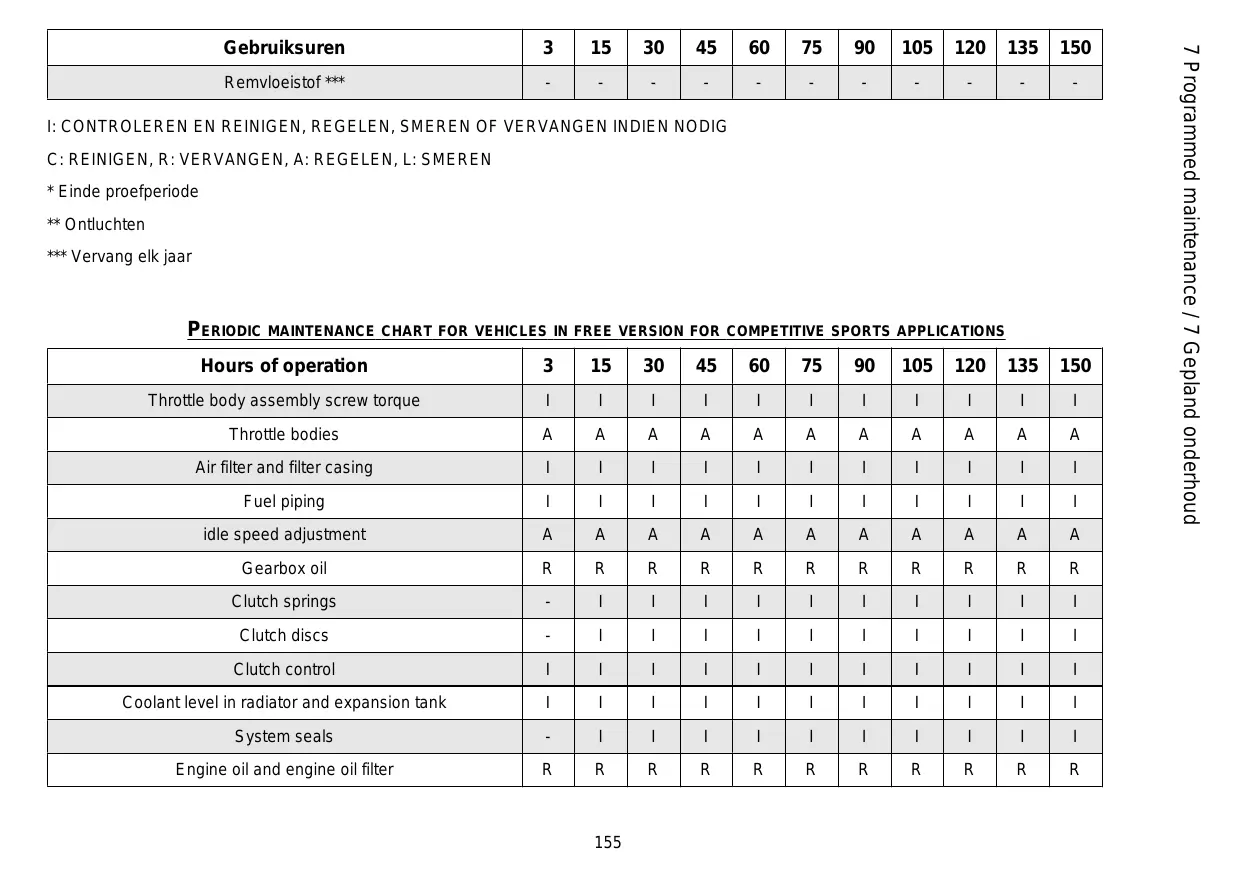
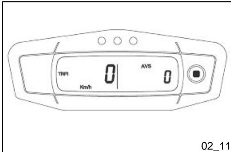
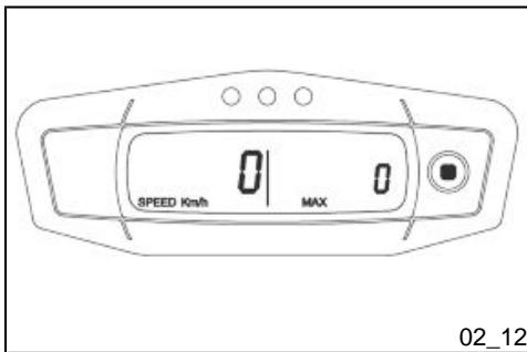
Digital display (02_05, 02_06, 02_07, 02_08, 02_09, 02_10, 02_11, 02_12, 02_13, 02_14, 02_15)
The vehicle current speed is shown in km/h or mph on the left side of the display.
The number of kilometres or miles covered, according to the setting, is shown on the right side of the display.
SPEED - ODO
The vehicle current speed is shown in km/h or mph on the left side of the display.
The hours of engine operation are shown on the right side of the display.
SPEED - CLK
The vehicle current speed is shown in km/h or mph on the left side of the display.
The time is shown on the right side of the display.
CLOCK SETTING
The hours increase if you hold down the SCROLL button for at least 3 seconds. The minutes increase once the button is released after 3 seconds.
SPEED-H
The vehicle current speed is shown in km/h or mph on the left side of the display.
The number of kilometres or miles partially covered, according to the setting, is shown on the right side of the display.
SPEED - STP 1
The vehicle current speed is shown in km/h or mph on the left side of the display.
A chronometer is shown on the right side of the display.
Hold down the SCROLL button for at least 3 seconds to activate this function
1st activation - start
2nd activation - stop
3rd activation - reset
SPEED - TRIP 1
1^ activering - start
2^ activering - stop
3^ activering - nulstelling
SPEED - AVS 1
The vehicle current speed is shown in km/h or mph on the left side of the display.
The average speed is shown on the right side of the display. This information is generated when TRIP 1 is activated.
SPEED - Max speed
The vehicle current speed is shown in km/h or mph on the left side of the display.
The maximum speed in the current unit of measurement is shown on the right side of the display.
Hold down the SCROLL button for at least 3 seconds to reset this function.
SPEED - TRIP 2
The vehicle current speed is shown in km/h or mph on the left side of the display.
The number of kilometres or miles partially covered, according to the setting, is shown on the right side of the display.
Hold down the SCROLL button for at least 3 seconds to reset this function.
SPEED - AVS 1
The vehicle current speed is shown in km/h or mph on the left side of the display.
The numbers for engine revolutions per minute are shown on the right side of the display.
SPEED - RPM
UNIT OF MEASUREMENT CONVERSION
Start the vehicle while holding down the SCROLL button until the "km/h" symbol is displayed.
The "Km/h" and "Mph Miles" symbols will be shown alternately.
Push the SCROLL button again when the desired unit of measurement is shown.
OMZETTING VAN DE MEETEENHEID
The ignition switch is in front of the left radiator.
The vehicle is supplied with two keys (one is the spare key).
The lights go off when the ignition switch is set to «OFF».
NOTE
THE LIGHTS TURN ON AUTOMATICALLY UPON THE ENGINE STARTUP.
Locking the steering wheel (02_17)
To lock the steering:
- Turn the handlebar completely to the left.
- Push in the key and turn it anticlockwise (to the left), move the handlebar slowly to the right until the key is turned to the right while still pressed.
- Remove the key.
Switch direction indicators (02_19)
To indicate left turn, turn the switch «4» to the left; to indicate right turn, turn the switch «4» to the right. To deactivate the turn indicator, press the «4» switch.
NOTE
ELECTRICAL COMPONENTS FUNCTION ONLY WHEN THE IGNITION KEY IS SET TO "ON"
High/low beam selector (02_20)
If the light switch «2» is set to the upper position, this activates the high-beam light; if it is set to the lower position, the low-beam light is switched on. In case of danger and/or emergency it is possible to activate high-beam flashing using the «1» button.
Lichtschakelaar (02_20)
Start-up button (02_21)
By pressing the starter button «2», the starter motor makes the engine rotate.
Startknop (02_21)
Engine stop switch (02_22)
It acts as an engine cut-off or emergency stop switch. With switch «1» set to «ON» is possible to start the engine; by pressing it into the «OFF» position, the engine stops.
CAUTION

DO NOT ACTIVATE THE ENGINE STOP SWITCH WHILE RIDING THE VEHICLE.
CAUTION

WITH ENGINE OFF AND THE IGNITION SWITCH SET TO 'ON' THE BATTERY MAY GET DISCHARGED.
CAUTION

WHEN THE VEHICLE IS NOT MOVING, AFTER THE ENGINE HAS BEEN STOPPED, SET THE IGNITION SWITCH TO «OFF»
Stopschakelaar motor (02_22)
Opening the saddle (02_23, 02_24)
- Turn the fastening clip.
-
Push the saddle forwards.
-
Remove the saddle.
Zadelopenen(02_23,02_24)
Write down the chassis and engine number in the specific space of this booklet. The chassis number can be used to order spare parts.
Identificatie (02_25, 02_26)
The engine number is stamped on the base of the left side engine crankcase.
Engine No
MOTORNUMMER
The chassis number is stamped on the right side of the headstock.
Chassis No.
FRAMENUMMER
| Front and rear disc brake | Check operation. Check brake lever travel when stationary and brake fluid level. Check for leaks. Check brake pads for wear. If necessary top-up with brake fluid. |
VOORAFGAANDE CONTROLES
| Fastener elements | Check that the fastener elements are not loose. Adjust or tighten if necessary. |
| Drive chain | Check it for backlash. |
| Fuel tank | Check the level and refill if necessary. Check the circuit for leaks or obstructions. Check that the tank cover closes correctly. |
| Coolant | The coolant level in the radiator must be such as to cover the grids. |
| Engine stop switch (RUN-OFF) | Check function. |
| Lights, warning lights, horn, rear stop light switch and electrical devices | Check function of horn and lights. Replace bulbs or repair any faults noted. |
Use premium unleaded petrol as per DIN 51 607, minimum octane rating of 95 (NORM) and 85 (NOMM).
To refuel:
- Unscrew and remove the fuel tank cap (1).
Refuel.
CAUTION

FUEL USED TO POWER INTERNAL COMBUSTION ENGINES IS HIGHLY FLAMMABLE AND CAN BECOME EXPLOSIVE UNDER SPECIFIC CONDITIONS. IT IS THEREFORE RECOMMENDED TO CARRY OUT REFUELLING AND MAINTENANCE PROCEDURES IN A VENTILATED AREA WITH THE ENGINE OFF. DO NOT SMOKE DURING REFUELLING AND NEAR FUEL VAPOURS, AVOID ANY CONTACT WITH NAKED FLAMES, SPARKS OR OTHER SOURCES WHICH MAY CAUSE THEM TO IGNITE OR EXPLODE.
DO NOT DISPOSE OF FUEL IN THE ENVIRONMENT.
KEEP OUT OF THE REACH OF CHILDREN
Tanken (03_01)
FUEL TANK CAPACITY (including reserve):
7.5 | (1.65 Ukgal)
Reservoir reserve:
2.21 (0.48 Ukgal)

VERMIJDT HET UITSTROMEN VAN BRANDSTOF UIT DE KLEP, OMDAT HIJ KAN VLAM VATTEN IN CONTACT MET DE GLOEIEND HETE OPPERVILAKKEN VAN DE MOTOR. WANNEER ER ONVRIJWILLIG BRANDSTOF WORDT GEMORST, CONTROLEERT MEN OF DE ZONE COMPLEET DROOG IS, VOORDAT MEN HET VOERTUIG START. BRANDSTOF ZET UIT DOOR DE WARMTE EN ONDER ACTIE VAN ZONNESTRALEN. VUL DETANK DUS NOOT TOT AAN DE RAND. SLUIT ZORGVULDIG DE DOP NA HET TANKEN. VERMIJDT DAT DE BRANDSTOF IN CONTACT KOMT MET DE HUID, VERMIJDT HET INADEMEN VAN DE DAMPEN, HET INSLIKKEN, EN HET OVERGIETEN VAN EEN TANK NAAR EEN ANDERE MET BEHULP VAN EEN BUIS.
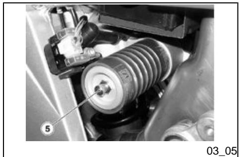
Rear shock absorbers adjustment (03_02, 03_03, 03_04, 03_05)
The rear suspension consists of a springshock absorber unit linked to the frame via silent-block and to the rear fork via a linkage system. To adjust the setting, the shock absorber is fitted with a set screw that adjusts hydraulic rebound damping (1), with a set screw (2) that adjusts hydraulic compression damping (low speed), with a knob (6) that adjusts hydraulic compression damping (high speed) and a ring nut that adjusts spring preloading (3) and a locking ring nut (4).
Regulering achterdempers (03_02, 03_03, 03_04, 03_05)
The standard setting of the rear shock absorber is adjusted so as to satisfy all main high and low speed riding conditions, both with reduced and full vehicle load. It is at any rate possible to insert personal settings, depending on vehicle utilisation.
TO COUNT THE NUMBER OF RELEAS ES AND/OR REVOLUTIONS OF ADJ USTMENT SETTINGS (1 - 2) ALWAYS START FROM THE MOST RIGID SETTING (WHOLE CLOCKWISE ROTATION OF THE SETTING).DO NOT FORCE THE SET SCREWS (1 - 2) TO TURN BEYOND THE END OF THE STROKE ON BOTH SIDES SO AS NOT DAMAGE THEM.
LET OP

VOOR HET TELLEN VAN HET AANTAL KLIKKEN EN/OF DRAAIEN VAN HET REGELREGISTER (1 - 2), VERTREKT MEN STEEDS VAN DE HARDSTE INSTELLING (VOLLEDIGE ROTATIE VAN HET REGISTER IN WIJZERZIN). FORCEER DE ROTATIE VAN HET REGELREGISTER NIET (1 - 2), NAAST DE EINDELOOP IN TWEE RICTINGEN, VOOR HET VERMIJDEN VAN MOGELIJKE BESCHADIGENG.
Using the specific spanner, slightly loosen the locking ring nut (4).
- Operate on the adjusting ring nut (3) to adjust the spring pre-loading (B).
- When the optimal adjustment level has been obtained, screw the locking nut ring (4) completely.
- Operate on screw (2) to adjust hydraulic compression damping at low speeds (see chart).
- Operate on knob (6) to adjust hydraulic compression damping at high speeds (see chart).
REAR SUSPENSION STANDARD ADJUSTMENT
| Shock absorber axial distance (A) | 473 ± 1.5 mm (18.6 ± 0.06 in) |
| (preloaded) Spring (B) length | 241 ± 1 mm (9.48 in) |
| Rebound adjustment, screw (1) | 16 clicks from fully closed |
| Compression damping adjustment, (low speeds), screw (2) | 13 clicks from fully closed |
STANDAARD REGELING VAN DE ACHTERSTE OPHANGING
Front fork adjustment (03_06, 03_07)
FRONT SUSPENSION
The front suspension consists of a hydraulic fork connected to the headstock by means of two plates. To adjust the vehicle setting, each fork stem is equipped with an upper screw 1 to adjust rebound damping and with a lower screw 2 to adjust compression damping.
FRONT FORK ADJUSTMENT
CAUTION
TO PREVENT DAMAGE, DO NOT FORCE THE ADJUSTER (1-2) BEYOND THE RESPECTIVE END OF TRAVEL IN Either Direction. SET BOTH STEMS WITH THE SAME SPRING PRELOAD AND DAMPING TOLERANCES: RIDING THE VEHICLE WITH A DIFFERENT ADJUSTMENT FOR THE TWO STEMS REDUCES ITS STABILITY. IF YOU INCREASE SPRING PRELOAD, YOU ALSO NEED TO INCREASE REBOUND DAMPING TO PREVENT SUDDEN JERKS WHILE RIDING.
The standard setting of the front fork is adjusted so as to satisfy all main high and low speed riding conditions, both with reduced and full vehicle load. It is at any rate possible to insert personal settings, depending on vehicle usage.
Front suspension standard adjustment:
- Rebound damping adjustment, screw (1): open (^*) 12 clicks from fully closed (^) ;
- Compression damping adjustment, screw (2): open (^) 12 clicks from fully closed (^*) (H);
Stems (A) (^) protrusion from top plate (excluding cover): 1 notch.
(^*) = Clockwise
(^**) = Anticlockwise
(^**) = Only use an Official aprilia Dealer for this type of adjustment
CAUTION
TO COUNT THE NUMBER OF RELEAS ES AND/OR REVOLUTIONS OF ADJUSTMENT SETTINGS (1 - -2) ALWAYS START FROM THE MOST RIGID
SETTING (WHOLE CLOCKWISE ROTATION OF THE SETTING).
CAUTION

SPORT SETTINGS MAY BE USED ONLY FOR OFFICIAL COMPETITIONS TO BE CARRIED OUT ON TRACKS, AWAY FROM NORMAL ROAD TRAFFIC AND WITH THE AUTHORISATION OF THE RELEVANT AUTHORITIES. USING SPORT SETTINGS AND RIDING THE VEHICLE ON ROADS AND MOTORWAYS WITH THESE SETTINGS IS STRICTLY FORBIDDEN.
LET OP
VOOR HET TELLEN VAN HET AANTAL KLIKKEN EN/OF DRAAIEN VAN HET REGELREGISTER (1-2), VERTEKT MEN STEEDS VAN DE HARDSTE INSTELLING (VOLLEDIGE ROTATIE VAN HET REGISTER IN WIJZERSZIN).
LET OP

DE REGELINGEN VOOR SPORTIEF GEBRUK MOGEN UITSLUITEND UITE GEVOERD WORDEN VOOR GEORGANISEERDE WEDSTRIJDEN OF SPORTIEVE EVENEMENTEN, DIE ALLESZINS IN EEN GESLOTEN CIRCUIT MOETEN GEREDEN WORDEN, NIET IN HET VERKEER, EN MET TOESTEMMING VAN DE RECHTSBEVOEGDE AUTORITEITEN. HET IS TEN STRENGSTE VERBODEN OM REGELINGEN VOOR SPORTIEF GEBRUK UIT TE VOEREN, EN OM MET HET VOERTUIG VOORZIEN VAN DEZE INRICHING TE RIJDEN OP WEGEN EN AUTOSTRADES.
Running in
Engine run-in is essential to ensure engine long life and correct operation. Twisty roads and gradients are ideal to
Inrijden
run in engine, brakes and suspensions effectively. Vary your riding speed during the run-in. In this way, you allow for the work of components to be "loaded" and then "unloaded", thus cooling the engine parts. Even if it is important to "strain" engine components during run-in, make sure not to overdo this.
Follow the guidelines detailed below:
- Do not twist the throttle grip abruptly and completely when the engine is working at a low revs, either during or after run-in.
for the first 3 operating hours, do not exceed 50% of the throttle grip travel and never go over 8000 rpm,
for the next 12 hours, do not exceed 75% of the throttle grip travel.
NOTE
EVEN AFTER THE RUNNING-IN PERIOD,AVOID RUNNING THE ENGINE TO TOP SPEED,WHEN THE LIMITER CUTS IN:
RXV 450 11500 rpm
RXV 550 11000 rpm
Get onto the bike in riding position.
Make sure that the stand has been fully retracted.
Make sure the light switch (1) is set to "low-beam".
- Set the engine stop switch (2) to RUN.
- The ignition screen is shown on the displayed for two seconds.
-
All warning lights in the instrument panel turn on for two seconds.
-
Block at least one wheel by operating one brake lever.
- Operate the clutch lever completely and set the gearshift lever to neutral [green warning light (N) on].
- Press the starter button «3» without opening the throttle and release it as soon as the engine starts.
DO NOT SET OFF SUDDENLY WHEN THE ENGINE IS COLD. RIDE AT LOW SPEED FOR SEVERAL KILOMETRES. THIS WILL ALLOW THE ENGINE TO WARM UP AND REDUCE POLLUTING EMISSIONS AND FUEL CONSUMPTION.
LET OP
VERMIJDT OM OP DE STARTKNOP «ON» TE DRUKKEN WANNEER DE MOTOR GESTART IS, WANT DE STARTMOTOR ZOU BESCHADIGD KUNNEN WORDEN.
LET OP
ALS GEVOLG VAN DE BEPERKTE BOUWTOLERANTIES VAN DE MOTOR EN DE DIMENSIONERING VOOR SPORTIEF GEBRUIK VAN DE SLIPKANALEN VAN DE OLIE, ZOU HET KUNNEN DAT DE MOTOR NIET START BIJ TEMPERATURED LIE DLAGER ZIJN DAN 0^ (32^) .VERMIJDTOM DOORTE GAAN MET POGINGEN OM TE STARTEN,OM DE STARTMOTOR NIET TE BESCHADIGEN.ER WORDT AANGERADEN OM HET VOERTUIG TE STALLEN IN GESLOTEN RUIMTES, VOORAL Tijdens DE WINTER.
LET OP
VERTREK NIET BRUUSK WANNEER DE MOTOR KOUD STAAT. OM DE EMISSIE VAN VERVUILENDE STOFFEN IN DE LUCHT EN HET BRANDSTOFVERBRUIK TE BEPERKEN, RAADT MEN AAN OM DE MOTOR OP TE WARMEN, DOOR DE EERSTE KILOMETERS AF TE LEGGEN AAN EEN BEPERKTE SNELHEID.
Stopping the engine (03_13)
It is very important to select an adequate parking spot, in compliance with road signals and the guidelines described below.
CAUTION

PARK ON SAFE AND LEVEL GROUND TO PREVENT THE VEHICLE FROM FALLING.
DO NOT LEAN THE vehicle ON A WALL OR LAY IT ON THE GROUND.
MAKE SURE THE VEHICLE AND SPECIALLY ITS HOT PARTS DO NOT POSE ANY RISK TO PEOPLE OR CHILDREN. DO NOT LEAVE YOUR VEHICLE UNATTENDED WITH THE ENGINE ON OR THE KEY IN THE IGNITION SWITCH.
DO NOT SEAT ON THE VEHICLE WHEN THE STAND IS LOWERED.
To park the vehicle:
- Select an appropriate parking spot.
- Stop the vehicle.
- Set the engine stop switch «1» to «OFF».
The red LED next to the switch should turn off.
Get off the vehicle.
Rest the vehicle on its stand.
Anti-theft device (03_14)
Six Days Version:
The Six Days version is supplied with an antitheft device (1) to be applied to the rear brake disc (2) (padlock with key lock).
NOTE

REMOVE THE ANTITHEFT DEVICE FROM THE REAR BRAKE DISC EACH TIME YOU USE THE VEHICLE OR WHEN CARRYING OUT ANY PROCEDURE WITH ENGINE OFF. FAILURE
Antidiefstalsystem (03_14)
Versie Six Days:
To place the vehicle on the stand:
- Grasp the left grip «1» and put the right hand on the upper rear part of the vehicle «2».
- Push the side stand «3» with your right foot, and extend it completely.
- With the stand fully extended, lean the vehicle to the side until the stand rests on the ground.
- Turn the handlebar fully leftwards.
CAUTION
MAKE SURE THE GROUND WHERE YOU HAVE PARKED IS UNOCCUPIED, FIRM AND LEVEL.
Standaard (03_15)
Safe driving (03_16, 03_17, 03_18, 03_19, 03_20, 03_21, 03_22, 03_23, 03_24, 03_25, 03_26, 03_27)
MAIN SAFETY RULES
To ride the vehicle it is necessary to comply with all legal requirements (driving license, minimum driving age, psychophysical performance, insurance, taxes and fees, registration, license plate, etc.).
You should practise using the vehicle in traffic-free areas and/or private property until you have become thoroughly acquainted with the vehicle.
Driving under the influence of medication, alcohol and narcotic drugs or psychotropic substances dramatically increases the risk of accidents.
Do not ride your vehicle if you feel tired or drowsy and always keep safe psychophysical riding conditions.
The main cause of motorcycle accidents is users' inexperience.
NEVER lend the vehicle to beginners and always make sure that the rider complies with all necessary requirements for a safe riding.
Strictly obey all national and local traffic signs and rules.
Avoid any abrupt and dangerous swerves for your own as well as others' safety (for example: rearing up on the
Veilig rijden (03_16, 03_17, 03_18, 03_19, 03_20, 03_21, 03_22, 03_23, 03_24, 03_25, 03_26, 03_27)
FUNDAMENTELE VEILIGHEIDSREGELS
back wheel, riding over the speed limit, etc.). Besides, always assess and bear in mind the road surface conditions, visibility, etc.
Do not knock obstacles that can damage the vehicle or cause loss of control.
Do not ride on the course of the vehicle in front just to improve your own speed.
CAUTION

ALWAYS RIDE WITH BOTH HANDS ON THE HANDLEBAR AND FEET ON THE FOOTRESTS (OR THE RIDER'S FOOTRESTS) IN THE ADEQUATE RIDING POSITION.
Never stand on your feet or stretch yourself while riding.
The rider should always be attentive, never get distracted or influenced by people, things or actions (never smoke, eat, drink, read, etc.) while riding.
Always use fuel and lubricants specific for the vehicle, of the type recommended in the "LUBRICANTS TABLE". Check fuel, oil and coolant frequently for correct level.
In case of an accident or after the vehicle has fallen down or suffered a sudden bump, make sure the control levers, piping, cables, brake circuit and main parts of the vehicle have not been damaged.
If necessary, take the vehicle to an Official aprilia Dealer to check especially the frame, handlebar, suspensions, safety components and any device the user cannot assess without the aid of a specialist.
Report any malfunction to the engineers and/or mechanics in order to facilitate their work.
Never ride the vehicle if the damage jeopardises safety.
Do not modify the position, angle or colour of: license plate, turn indicators, lighting devices and horn.
Any changes to the vehicle will void the warranty.
Any change introduced to the vehicle and the removal of original parts may jeopardise the vehicle performance and therefore reduce safety or even render the vehicle inappropriate for legal riding.
Comply with all national and local laws and regulations on vehicle equipment.
In particular do not introduce technical changes leading to improve performance and under no circumstances alter the original specifications of the vehicle.
Never race with vehicles.
Never ride off-road.
Before riding off, remember to put on the helmet and fasten it correctly. Make sure it is a homologated model, that it is undamaged, of the right size and that the visor is clean.
Wear appropriate protective clothes, preferably light-coloured and/or in reflective material. In this way you will be easily visible to other drivers, thus reducing the risk of being hit, and you will be better protected in case of falling.
Always wear tight-fitting clothes without open cuffs; avoid hanging strings, belts or ties; these or any other objects should not interfere with a safe riding when getting entangled with the riding elements or due to a special movement.
Never carry in your pockets objects that can be potentially dangerous in case of fall, like: pointed objects such as keys, pens, glass containers, etc. (the same rule applies to passengers).
KLEDING
User is personally responsible for the installation and use of the accessories.
While assembling accessories, make sure that they do not cover the sound or light alarm devices or affect their correct functioning, do not limit the suspension travel or the steering angle, do not obstruct control actuation or reduce the ground clearance and inclination angle at corners.
Do not use accessories that hinder access to the controls as they may increase the reaction time in case of an emergency.
Fairings and large windshields fitted to the vehicle may cause aerodynamic forces that affect the vehicle stability while riding, mainly at high speeds.
Make sure the accessory is firm and secured to the vehicle and that it does not pose any risks while riding the vehicle.
Do not add or modify electrical equipment that exceed the vehicle capacity as this may result in a sudden stop or a dangerous lack of power required to keep the sound and light alarm devices operative.
ACCESSIONS
aprilia advises using original accessories (aprilia genuine accessories).
Engine oil level (04_01, 04_02)
Checking and topping up engine oil level
CAUTION

DO NOT SPILL OIL!
AVOID SPILLING OIL OVER COMPONENTS, THE AREA YOUR ARE WORKING IN AND ITS SURROUND. REMOVE ANY TRACE OF OIL CAREFULLY.
IN THE EVENT OF LEAKS OR MALFUNCTION, CONTACT AN Official aprilia Dealer.
Peil motorolie (04_01, 04_02)
THIS TYPE OF VEHICLE HAS SEPARATE LUBRICATION CIRCUITS FOR ENGINE AND TRANSMISSION/CLUTCH. OIL LEVEL CHECK AND REPLACEMENT MUST BE CARRIED OUT FOR BOTH CIRCUITS.
CAUTION
THE ENGINE MUST BE WARM TO CHECK ENGINE OIL LEVEL. IF ENGINE OIL LEVEL IS CHECKED WHEN
Voor de contrôle:
LET OP
DEZE VOERTUIGEN ZIJN UITGERUST MET EEN GESCHEIDEN SMEERCICCUIT VOOR VERSNELLINGSBAK/KOPPELING EN MOTOR. DE CONTROLLE VAN DE PEILEN EN DE VERVANGING VAN DE OLIE MOET UITGEVOERD WORDEN OP BEIDE CIRCUITS.
THE ENGINE IS COLD, THE OIL MAY GO TEMPORARILY BELOW THE MINIMUM LEVEL. THIS IS NOT A PROBLEM.
LET OP
DE CONTROLE VAN DE MOTOROLIE MOET UITGEVOERD WORDEN BIJ WARME MOTOR. WANNEER MEN DE CONTROLE VAN HET PEIL VAN DE MOTOROLIE BIJ KOUDE MOTOR UITVOERT, ZOU DE OLIE TijDELIJK ONDER HET MIN. PEIL KUNNEN DALEN. DIT VORMT GEEN ENKEL PROBLEEM.
04_01
NOTE
IN ORDER TO WARM-UP THE ENGINE AND BRING THE OIL TO THE RIGHT TEMPERATURE, RIDE THE VEHICLE FOR A SHORT PERIOD OF TIME (10 - 15 MIN), KEEP THE ENGINE RUNNING AT IDLE FOR AT LEAST 30 SECONDS AFTER YOU HAVE COME TO A HALT, THEN CUT OFF THE ENGINE.
N.B.
OM DE MOTOR OP TE WARMEN EN DE OLIE OP TEMPERATUUR TE BRENGEN, GEBRUIKT MEN HET VOERTUIG VOOR EEN KORTPE PERIODE (10 - 15 MIN), LAAT MEN DE MOTOR AAN HET MINIMUM TOERENTAL WERKEN MET HET VOERTUIG STIL VOOR MINSTENS 30 SECONDEN, EN LEGT MEN DAARNA DE MOTOR STIL.
- Hold the vehicle level with the two wheels on the ground.
- Check the oil level
using the relevant transparent dipstick «1».
MAX = maximum level
MIN = minimum level
IF YOU RIDE THE VEHICLE IN A SPORTY FASHION, SOME OIL SPLATTER MAY GET TO THE AIR FILTER HOUSING THROUGH THE ENGINE VENT.
CAUTION

DO NOT GO BEYOND THE MAX AND BELOW THE MIN LEVEL MARKS TO AVOID SEVERE ENGINE DAMAGE.
Engine oil change (04_03, 04_04, 04_05, 04_06)
- Park the vehicle on firm and level ground.
Rest the vehicle on its stand.
Vervanging van de motorolie (04_03, 04_04, 04_05, 04_06)
- Stop the engine and let it cool off so that the oil in the crankcase flows down and cools as well.
- Remove the oil sump guard.
- Unscrew and take out the oil filler plug (1).
- Place a container to collect the oil underneath the engine oil drainage plug on the flywheel side.
- Unscrew and remove the oil drainage plug (2) and then drain all the engine oil.
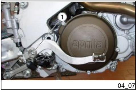
Gearbox oil level (04_07, 04_08, 04_09, 04_10)
CAUTION

GEARBOX OIL LEVEL MUST BE CHECKED WHEN THE ENGINE IS WARM.
Versnellingsbak oliepeil (04_07, 04_08, 04_09, 04_10)
LET OP

DE CONTROLE VAN HET OLIEPEIL VAN DE VERSNELLINGSBAK MOET UITGEVOERD WORDEN BIJ WARME MOTOR.
- Stop the engine.
- Wait some minutes for the oil to flow from the transmission to the clutch.
- Keep the vehicle upright with the two wheels on the ground.
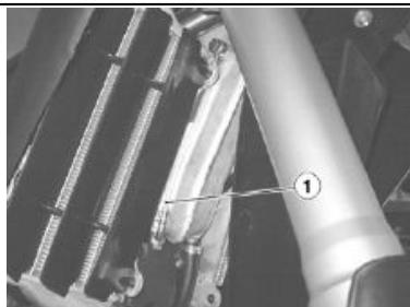
- Remove the rear brake lever by undoing the screw (1); collect the washer.
- Remove the filler cap (3).
Top-up with oil up to the cap/ dipstick (2) opening.
Indien nodig:
- Wait some minutes to allow the oil to flow from the clutch to the transmission. Then check the oil level again.
- Refit the rear brake lever, remember to insert the washer between the lever and the crankcase, by tightening the screw (1).
REPLACEMENT
NOTE
TO ENSURE EASIER AND FULL OIL DRAINAGE THE OIL MUST BE HOT AND THEREFORE MORE FLUID.
Lower the oil pan guard.
- Place a container with suitable capacity under the drainage plug (4).
- Unscrew and remove the drainage plug (4).
- Unscrew and remove the filler plug (3).
- Drain the oil into the container; allow several minutes for oil to drain out completely.
- Check and if necessary, replace the drainage plug (4) sealing washers.
- Screw and tighten the drainage plug (4).
- Remove the rear brake lever by undoing the screw (1); collect the washer.
- Unscrew and remove the cap/ dipstick (2).
Pour in new oil until it reaches the cap/dipstick opening (2).
- Wait some minutes to allow the oil to flow from the clutch to the transmission.
- Then check the oil level again.
- Tighten the filler cap (3).
CAUTION
THE OIL FLOW FROM THE CLUTCH TO THE TRANSMISSION AND FROM THE TRANSMISSION TO THE CLUTCH CAN BE PARTICULARLY SLOW WHEN THE OIL OR ENGINE TEMPERATURE IS LOW.
Spark plug dismantlement (04_11, 04_12, 04_13)
At regular intervals, remove the spark plugs and clean off any carbon deposits or replace them as required.
Demonteren van de bougie (04_11, 04_12, 04_13)
Demonteer periodiek de bougie, reinig ze van koolstofafzettingen, en verrang ze indien nodig.
CAUTION

ALWAYS REPLACE BOTH SPARK PLUGS, EVEN IF ONLY ONE NEEDS REPLACING.
LET OP

OOK WANNEER SLECHTS EEN VAN DE BOUGIES MOET VERVANGEN WORDEN, VERVANGT MEN STEEDS BEIDE BOUGIES.
In order to gain access to the spark plugs: Om de bougies te bereiken:
CAUTION

BEFORE CARRYING OUT THE FOLLOWING OPERATIONS AND IN ORDER TO AVOID BURNS, LEAVE ENGINE AND MUFFLER TO COOL OFF TO AMBIENT TEMPERATURE.
LET OP

VOORALEER MEN DE VOLGENDE HANDELINGEN UITVOERT, LAAT MEN DE MOTOR EN DE UITLAAT AFKOELEN TOT DEZE DE OMGEVINGSTEMPERATUUR HEBBEN BEREIKT, OM MOGELIJKE BRANDWONDEN TE VERMIJDEN.
- Place the vehicle on the stand.
NOTE

THE VEHICLE HAS A SPARK PLUG (2) FOR EACH CYLINDER. THE FOLLOWING STEPS RELATE TO JUST ONE SPARK PLUG BUT APPLY TO BOTH.
Checking and cleaning:
- Check that the electrodes and the insulator of the spark plug (2) do not show signs of carbon deposits or corrosion. If necessary, clean them using a short blast of compressed air.
Replace spark plug (2) if its insulator is cracked, the electrodes show signs of corrosion or excessive deposits or the top of the central electrode gets rounded.
- Check the gap between electrodes with a feeler thickness gauge.
CAUTION

DO NOT ATTEMPT TO READJUST THE ELECTRODE GAP.
Characteristic
Electrode gap
$$ 0. 7 \pm 0. 8 \mathrm {m m} (0. 0 2 7 \pm 0. 0 3 1 \mathrm {i n}) $$
If the electrode gap is different from the prescribed gap, replace the spark plug (2).
Make sure the washer is in good conditions.
- Manually screw the spark plug (2) to avoid damaging the thread.
- Tighten using the spanner supplied in the tool kit. Make each spark plug (2) complete 1/2 of a turn to compress the washer.
CAUTION

IT IS ESSENTIAL TO TIGHTEN THE SPARK PLUG (2) PROPERLY. A LOOSE SPARK PLUG MAY CAUSE ENGINE OVERHEATING AND RESULT IN SEVERE DAMAGE.
Locking torques (N^*m)
Spark plug USA
8.85 lbf ft (12 Nm)
- Position the spark plug tube (1) correctly so that it does not get detached due to engine vibrations.
Removing the air filter (04_14, 04_15)
- Remove the saddle.
- Remove the side fairings.
- Lift the tank paying attention to the fuel pipe.
- Release the air filter cover by gripping and lifting the handles from both sides.
Take the filter casing cover off together with the air filter paying attention not to damage the control unit connector (remove it if necessary).
NOTE
DURING FUEL TANK LIFTING AND REFITTING, MANUALLY PLACE THE FUEL PIPE AND CHECK ITS CORRECT POSITIONING.
CAUTION
OIL THE SPONGE FILTER AS INSTRUCTED IN THE SCHEDULEDMAINTENANCE CHART.
NOTE
WHEN REFITTING THE AIR FILTER, ENSURE THAT ITS HOUSING IS PERFECTLY CLEAN. REMOVE ANY TRACE OF DIRT THAT MAY HAVE ENTERED DURING REMOVAL. DURING REASSEMBLY, MAKE SURE THAT THE AIR VENTS ARE INSERTED CORRECTLY.
IN THE EVENT OF A FALL, CLEAN THE AIR FILTER AND ITS HOUSING CAREFULLY, REMOVING ANY TRACES OF OIL WHICH MAY HAVE ENTERED FROM THE OIL TANK THROUGH THE OIL VAPOURS BREATHER PIPES.
CAUTION

REMOVE THE AIR FILTER COVER ONLY WHEN THE VEHICLE IS PERFECTLY CLEAN SO AS TO AVOID THAT ANY TRACE OF DIRT MAY INGRESS THE HOUSING.
LENTIJDENS DE VERWIJDERING. BIJ DE HERMONTAGE LET MEN OP VOOR DE CORRECTE PLAATSING VAN DE LUCHTINLATEN.
LET OP

LET OP DAT DE TREKDRAAD VAN DE TANK VOOR GEEN ENKELE REDEN DE POSITIEVE POOL VAN DE ACCU RAAKT.
LET OP

WANNEER DE LUCHTFILTER EN DE FILTERKIST GEVALLEN ZIJN, REINIGT MEN ZORGVULDIG, ZODATER GEEEN OLIE MEER AANWEZIG IS DIE EVENTUEEL VAN DE OLIETANK LANGS DE ONTLUCHTINGSBUIS VAN DE OLIEDAMPEN ZOU BINNENGKOMEN ZIJN.
LET OP

VOER DE HANDELING VAN HET VERWIJDEREN VAN HET LUCHTFILTERDEKSEL ENKEL UIT WANNEER DEMOTOR PERFECT REIN IS, OM TE
Cooling fluid level (04_16, 04_17)
Do not use the vehicle if the coolant is below the minimum level.
CAUTION

COOLANT IS TOXIC IF INGESTED; CONTACT WITH YOUR EYES OR SKIN MAY CAUSE IRRITATION. IF THE FLUID GETS IN CONTACT WITH THE EYES OR SKIN, RINSE REPEATEDLY WITH PLENTY OF WATER AND SEEK MEDICAL ADVICE. IF SWALLOWED, INDUCE VOMITING, RINSE MOUTH AND THROAT WITH PLENTY OF WATER AND SEEK MEDICAL ADVICE IMMEDIATELY.
Peil koelvloeistof (04_16, 04_17)
Coolant solution is 50% water and 50% antifreeze fluid.
De oplossing van de koelvloeistof staatuit 50% water en 50% antivries.
This is the ideal mixture for most operating temperatures and provides good corrosion protection.
It is advisable to use the same mixture even in hot weather as this minimises loss due to evaporation and the need of frequent top-ups.
Less water evaporation means fewer mineral salts depositing in the radiators, which helps preserve the efficiency of the cooling system.
When the external temperature drops below zero degrees centigrade, check the cooling system frequently and add more antifreeze solution if needed (up to 60% max.).
Use distilled water in the coolant mixture to avoid damaging the engine.
CAUTION

DO NOT REMOVE THE RADIATOR CAP «1» WHEN THE ENGINE IS HOT SINCE COOLANT IS UNDER PRESSURE AND VERY HOT. CONTACT WITH SKIN OR CLOTHES MAY CAUSE SEVERE BURNS AND/OR INJURIES.
Checking and topping up
CAUTION

WAIT FOR THE ENGINE TO COOL DOWN BEFORE CHECKING OR TOPPING-UP THE COOLANT LEVEL.
- Shut off the engine and wait until it cools off.
- Park the vehicle on firm and level ground.
- Keep the vehicle upright with the two wheels on the ground.
- Turn the radiator cap (1) anticlockwise just one click.
- Wait for some seconds so that any pressure in the system may be purged.
- Turn the radiator cap (1) anticlockwise again and remove it.
Make sure the fluid covers the radiator plates completely. - Also check the level in the expansion tank (under the engine sump cover) through the appropriate sight glass.
The level should be between the MIN and MAX reference marks.
CAUTION

DO NOT ADD ADDITIVES OR OTHER SUBSTANCES TO THE FLUID.
IF A FUNNEL OR ANY OTHER ELEMENT IS USED, MAKE SURE IT IS PERFECTLY CLEAN.
- If required, top-up with coolant until the radiator plates are covered. Do not exceed this level; otherwise, the coolant will spill during engine operation. When using a funnel or any other element, make sure it is perfectly clean.
- Refit the radiator cap (1).
CAUTION
IN THE EVENT OF EXCESSIVE COOLANT CONSUMPTION, CHECK COOLING SYSTEM FOR LEAKS.
HAVANYMALFUNCTION REPAIRED BY AN Official aprilia Dealer.
Checking the brake oil level (04_18, 04_19, 04_20, 04_21)
Check the brake fluid level following the instructions on the scheduled maintenance table.
The information provided below relates to an individual braking system but is applicable to both.
NOTE
THIS VEHICLE IS EQUIPPED WITH FRONT AND REAR DISC BRAKES, EACH OPERATED BY AN INDEPENDENT HYDRAULIC CIRCUIT.
CAUTION

UNEXPECTED CLEARANCE VARIATIONS OR ELASTIC RESISTANCE IN THE BRAKE LEVER ARE DUE TO FAILURE IN THE HYDRAULIC CIRCUIT. CONTACT AN Official aprilia Dealer IN CASE OF DOUBTS ON THE CORRECT OPERATION OF THE BRAKING SYSTEM OR WHEN UN
RINSE CAREFULLY ALL BODY PARTS WHICH HAVE COME INTO CONTACT WITH THE FLUID AND, SHOULD THE FLUID COME INTO CONTACT WITH THE EYES, SEEK
MEN NIET IN STAAT IS OM DE NORMALE CONTROLEHANDELINGEN UIT TE VOEREN, WENDT MEN ZICH TOT EEN Officièle aprilia Dealer.
LET OP

LET VOORAL OP DAT DE REMSCHIJVEN NIET VETTIG OF INGEVET ZIJN, VOORAL NA HET UITVOEREN VAN DE ONDERHOUDSHANDELINGEN OF DE CONTROLE.
CONTROLER OF DE REMBUIZEN NIET IN ELKAAR GEDRAID OF VERSLETEN ZIJN.
LET OP DAT ER GEEN WATER OF STOF TOEVALLIG IN HET CIRCUIT KOMT.
BIJ ONDERHOUDSHANDELINGEN AAN HET HYDRAULISCH CIRCUIT, RAADT MEN AAN OM LATEX HANDSCHOENEN TE GEBRUIKEN.
DE REMVLOEISTOF ZOU IRRITATIE KUNNEN VEROORZAKEN WANNEER HET IN CONTACT KOMT MET DE HUID OF DE OGEN.
MEDICAL ADVICE OR CONTACT AN OPHTHALMOLOGIST.
CAUTION

DO NOT DISPOSE OF THE FLUID INTO THE ENVIRONMENT.
CAUTION

KEEP OUT OF THE REACH OF CHILDREN.
CAUTION

WHEN YOU USE THE BRAKE FLUID, MAKE SURE NOT TO SPILL IT ONTO PLASTIC OR PAINTED COMPONENTS AS IT WILL DAMAGE THEM BEYOND REPAIR.
LET OP

WAS ZORGVULDIG DE DELEN VAN HET LICHAAAM DIE IN CONTACT ZIJN GEKOMEN MET DE VLOEISTOF, WENDT ZICH BOVENDIEN TOT EEN OOGARTS OF EEN ARTS WANNEER DE VLOEISTOF IN CONTACT KOMT MET DE OGEN.
LET OP

LOOS DE VLOEISTOF NIET IN HET MI-LIEU.
LET OP

BUITEN BEREIK VAN KINDEREN HOUDEN
LET OP

WANNEER MEN REMVLOEISTOF GEBRUIKT MOET MEN OPLETTEN OM HET NIET TE MORSEN OP DE PLASTIC OF GELAKTE DELEN, OMDAT HET ONHERSTELBARE SCHADE ZAL AANRICHTEN.
BRAKES ARE THE MOST IMPORTANT COMPONENTS TO ENSURE SAFETY AND THEREFORE THEY HAVE TO BE ALWAYS IN PERFECT CONDITIONS; CHECK THE BRAKES BEFORE EACH RIDE.
REPLACE THE BRAKE FLUID ACCORDING TO THE SCHEDULED MAINTENANCE TABLE.
USE THE BRAKE FLUID SPECIFIED IN THE RECOMMENDED PRODUCT TABLE.
DE REMMEN ZIJN DE ONDERDELEND DIE HET MEEST DE VEILIGHEID GARANDEREN, EN MOETEN DUS STEEDS PERFECT EFFICIENT WORDEN GEHOUDEN; CONTROLER ZE VOOR ELKE REIS.
VOER DE VERVANGING VAN DE REMVLOEISTOF UIT OP BASIS VAN DETABEL VAN HET GEPROGRAMMEERD ONDERHOUD.
GEBRUK DE SPECIFIEKE REMVLOEISTOF DIE WORDT AANGEDUID IN DE TABEL VAN DE AANBEVOLEN PRODUCTEN.
Brake fluid decreases gradually in the reservoir as the brake pads wear down, to compensate the wear automatically.
The front brake fluid reservoir (1) is placed near the front brake lever connection.
The rear brake fluid reservoir (2) is integrated in the brake pump fastened to the frame, on the right side, near the fork.
Check the brake fluid level in the reservoirs before setting off.
CAUTION

DO NOT USE YOUR VEHICLE IF A FLUID LEAK IN THE BRAKING CIRCUIT IS DETECTED.
Front brake
Checking
- Place the vehicle upright and keep the handlebar right.
Make sure the fluid level in the reservoir (1) is above the MIN level reference mark.
MIN = minimum level
MAX = maximum level
If the fluid does not reach the MIN. mark
CAUTION
- Check the brake pads and discs for wear.
If the pads and/or the disc do not need replacing, top up the fluid.
CAUTION
RISK OF BRAKE FLUID SPILLING. DO NOT PULL THE FRONT BRAKE LEVER WHEN THE SCREWS (3) ARE LOOSE OR, MAINLY, WHEN THE BRAKE FLUID RESERVOIR CAP (4) HAS BEEN REMOVED.
- Undo the screws (3) of the brake fluid reservoir using a short Phillips screwdriver.
CAUTION
AVOID PROLONGED AIR EXPOSURE OF THE BRAKE FLUID. THE BRAKE FLUID IS HYGROSCOPIC AND ABSORBS MOISTURE WHEN IS IN CONTACT WITH THE AIR. LEAVE THE BRAKE FLUID RESERVOIR «1» OPEN ONLY FOR THE TIME NEEDED TO COMPLETE THE TOPPING UP PROCEDURE.
- Top up the reservoir «1» with the brake fluid, until you go beyond the MIN minimum level mark.
- Keep the vehicle upright.
- Check that the liquid contained in the reservoir is higher than the MIN. mark.
MIN = minimum level
If the fluid does not reach the MIN. mark
CAUTION
- Check the brake pads and discs for wear.
If the pads and/or the disc do not need replacing, top up the fluid.
Topping up
CAUTION
RISK OF BRAKE FLUID SPILLING. DO NOT PULL THE FRONT BRAKE LEVER WHEN THE SCREWS (6) ARE LOOSE OR, PRIMARILY, WHEN THE BRAKE FLUID RESERVOIR CAP (7) IS REMOVED.
Using a wrench, unscrew the two screws (6) of the brake fluid reservoir (2).
CAUTION
AVOID PROLONGED AIR EXPOSURE OF THE BRAKE FLUID. THE BRAKE FLUID IS HYGROSCOPIC AND ABSORBS MOISTURE WHEN IS IN CONTACT WITH THE AIR. LEAVE THE BRAKE FLUID RESERVOIR «2» OPEN ONLY FOR THE TIME NEEDED TO COMPLETE THE TOPPING UP PROCEDURE.
- Top-up the reservoir (2) with the brake fluid until the level is over the MIN level reference mark.
- Remove the saddle.
-
Unscrew and remove the negative wire fastening screw, keeping the washer.
-
Unscrew and remove the negative wire fastening screw, keeping the washer.
Accu (04_22, 04_23, 04_24)
Checking the fuses is necessary whenever an electrical component fails to operate or is malfunctioning or when the engine does not start.
Check the auxiliary fuses first and then the main 30A fuse.
To check:
- Set the ignition switch to (OFF) to avoid an accidental short circuit.
- Remove the right side fairing by undoing the two screws (1) and slide if off from its seat.
- Lift the cover (2) of the auxiliary fuse box.
Take out one fuse at a time and check whether the filament (3) is broken.
Before replacing the fuse, find and solve, if possible, the reason that caused the problem.
If the fuse is damaged, replace it with one of the same amperage.
NOTE
IF THE SPARE FUSE IS USED, REPLACE WITH ONE OF THE SAME TYPE IN THE CORRESPONDING FITTING.
- Remove the left side cover, following the same procedure as for the right side cover.
- Follow the same steps described above for the auxiliary fuses also for the main fuses.
| (2) 15A fuse | ECU relay power |
| (3) 15A Fuse | Taillights, indicators, horn, instrument panel, stop light |
| (4) 15A Fuse | ECU relay energising |
| (5) 7.5A fuse | Injector coils |
| (6) 7.5A fuse | Electric fan |
| (7) 7.5A fuse | Fuel pump |
THREE FUSES FUSES<8>.
ARE SPARE
N.B.
DRIE ZEKERINGEN ZIJN RESERVEZEKERINGEN «8».
MAIN FUSES DISTRIBUTION
| 30A fuse | Battery recharge (there is just one fuse, the second one is spare). |
SCHIKKING VAN DE HOOFDZEKERINGEN
BEFORE CHANGING A BULB, CHECK THE FUSES.
Lampjes
N.B.
VOORALEER MEN EEN LAMPJE VERVANGT, CONTROLEERT MEN DE ZEKERINGEN.
Front light group (04_30, 04_31, 04_32, 04_33, 04_34)
In the front headlight there are:
Two tail light bulbs «1».
One low-beam / high-beam light bulb «2».
Koplampset (04_30, 04_31, 04_32, 04_33, 04_34)
- Rest the vehicle on its stand.
- Undo the two upper screws.
- Slide off the front cowl from the mudguard seats.
Side light lamp «1»
- Slide off the tail light bulb and replace it with another of the same type.
High/low beam light bulb《2》
- Hold the bulb electrical connector «3», pull and disconnect it from the bulb holder.
- Slide off the cover «4» from the parabole fitting and from the bulb connectors.
- Release the two ends of the retaining spring «5» located in the bulb holder.
- Extract the bulb from its fitting.
Upon refitting:
- Fit a bulb of the same type adequately.
- Slide in the cover «4» in the bulb connectors and the parabole fitting.
- Connect the bulb electrical connector «3».
Voor de verwanging:
Headlight adjustment (04_35, 04_36)
NOTE
IN COMPLIANCE WITH LOCAL LEGAL REQUIREMENTS, SPECIFIC PROCEDURES MUST BE FOLLOWED WHEN CHECKING LIGHT BEAM ADJUSTMENT.
Afstellen van de koplamp (04_35, 04_36)
N.B.
OP BASIS VAN WAT WORDT VOORGESCHREVEN DOOR DE VAN KRACHT ZIJNDE WETGEVING IN HET LAND VAN GEBRUIK VAN HET VOERTUIG, MOETEN ER VOOR DE CONTROLLE VAN DE RICHTING VAN DE LICHTBUNDEL SPECIFIEKE PROCEDURES UITGEVOERD WORDEN.
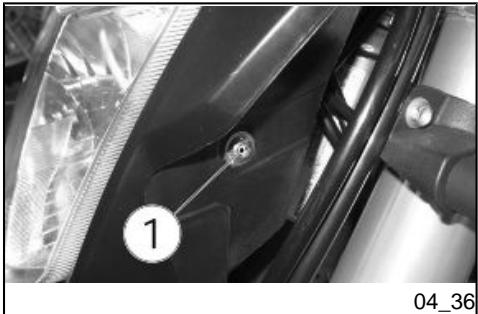
For a quick check of the correct direction of the front light beam:
- Place the vehicle 10m away from a vertical wall and make sure the ground is level.
- Turn on the low-beam light, sit on the scooter and check that the light beam projected to the wall is a little below the headlight horizontal straight line (about 9/10 of the total height).
To adjust the light beam:
- Working from both sides, undo screw «1».
- Adjust the headlamp until the desired position is obtained
- Working from both sides, tighten screw «1».
Front and rear disc brake (04_37, 04_38, 04_39, 04_40)
CAUTION

BRAKES ARE THE MOST IMPORTANT COMPONENTS TO ENSURE SAFETY AND THEREFORE THEY HAVE TO BE ALWAYS IN PERFECT CONDITIONS;
The front braking system has single disc (left side).
The rear braking system has single disc (right side).
The information provided below relates to an individual braking system but is applicable to both.
Brake fluid decreases gradually in the reservoir (1-2) as the brake pads wear down, to compensate the wear automatically.
The front brake reservoir «1» is placed near the front brake lever connection. The rear brake fluid reservoir «2» is integrated in the brake pump fastened to the frame near the fork.
Check the brake fluid level in the reservoirs «1» «2» and check brake pads for wear before setting off.
Checking brake pads for wear
Disc brake pad wear depend on the use, the riding style and the roads.
CAUTION

WEAR IS GREATER WHEN RIDING ON DIRTY AND WET ROADS OR OFFERED.
To carry out a quick pad check:
Rest the vehicle on its stand.
Check the front brake calliper pads:
- Visually inspect the area between brake disc and brake pads looking from the bottom up the front end;
Checking the rear brake calliper pads:
- Visually inspect the area between brake disc and brake pads looking from the bottom up the rear end;
NOTE
EXCESSIVE WEAR OF THE FRICTION MATERIAL MAKES THE PAD METAL SUPPORT GET INTO CONTACT WITH THE DISC, WHICH RESULTS IN A METALLIC NOISE AND SPARKS IN THE CALLIPER; THEREFORE, BRAKING EFFICIENCY AND DISC SAFETY AND INTEGRITY ARE AT RISK.
When the lining material of even just one of the brake pads is worn down to nearly 1.5mm (0.06 in) (or even if one of the wear indicators is no longer visible), replace both brake pads.
CAUTION
TAKE YOUR SCOOTER TO AN Official aprilia Dealer TO HAVE DISCS REPLACED.
Take some measures to avoid the side effects of not using the vehicle. Also, carry out general maintenance and checks before garaging the vehicle as one can forget to do so afterwards.
Proceed as follows:
- Remove the battery.
- Wash and dry the vehicle.
Inflate tyres. - Store the vehicle in cool, dry place, with minimum temperature variations and not exposed to sun rays.
- Wrap and tie a plastic bag around the muffler exhaust end to keep moisture out.
NOTE
PLACE A SUITABLE SUPPORT UNDER THE VEHICLE TO KEEP BOTH WHEELS OFF THE GROUND.
Uncover and clean the vehicle.
NOTE
TAKE THE PLASTIC BAGS OFF THE EXHAUST PIPE OPENING.
- Uncover and clean the scooter.
- Check battery charge and install.
- Refill the fuel tank.
- Carry out the pre-ride checks.
CAUTION

TEST RIDE THE VEHICLE AT MODERATE SPEED FOR A FEW KILOMETRES IN AN AREA AWAY FROM TRAFFIC.
N.B.
VERWIJDER DE PLASTIC ZAKJES VAN DE UITEINDEN VAN DE UITLAAT.
Cleaning the vehicle
Clean the scooter frequently if exposed to adverse conditions, such as:
Air pollution (cities and industrial areas).
Salinity and humidity in the atmosphere (seashore areas, hot and wet weather).
Special environmental/seasonal conditions (use of salt, anti
icing chemical products on the roads in winter).
- Pay special attention to prevent deposits on the bodywork, such as industrial dusts and pollutants, tar spots, dead insects, birds droppings, etc. Avoid parking under trees. During some seasons, resins, fruits or leaves containing aggressive chemical substances that may damage the paintwork may fall from trees.
CAUTION

BEFORE WASHING THE VEHICLE, COVER THE ENGINE AIR INTAKES AND THE EXHAUST PIPES.
CAUTION


AFTER CLEANING YOUR VEHICLE, BRAKING EFFICIENCY MAY BE TEMPORARILY AFFECTED DUE TO THE PRESENCE OF WATER ON THE FRICTION SURFACES OF THE BRAKING CIRCUIT. ALLOW LONGER BRAKING DISTANCES TO PREVENT ACCIDENTS. BRAKE REPEATEDLY TO RESTORE NORMAL OPERATION. CARRY OUT THE PRE-RIDE CHECKS.
During transport the vehicle must be well secured in an upright position and first gear must be engaged, to avoid fuel, oil and coolant leaks.
IN CASE OF FAILURE, DO NOT HAVE THE VEHICLE TOWED. ASK FOR ROAD ASSISTANCE SERVICE.
Vervoer
The RXV model features a chain with master link.


EXCESSIVE CHAIN SLACKENING MAY CAUSE IT TO COME OFF THE PINION, WHICH IN TURN COULD CAUSE AN ACCIDENT OR SEVERE DAMAGE TO THE VEHICLE. CHECK THE CHAIN SLACK ON A REGULAR BASIS AND ADJUST IT AS NECESSARY. TO CHANGE THE CHAIN TAKE YOUR VEHICLE TO AN Official aprilia Dealer, WHO WILL PROVIDE ACCURATE, PROMPT SERVICE.
Transmissieketting
- Stop the engine.
- Place the vehicle on the stand.
- Engage neutral gear.
- Check that vertical oscillation at the middle point between pinion and crown on the lower part of the chain is of about 20 ÷ 25 ~mm (0.79 ÷ 0.98 in).
- Move the vehicle forward so as to check vertical oscillation in other positions too. The slack should remain constant during all wheel rotation phases.
If the slack is uniform, but higher or lower than 20 ÷ 25 ~mm (0.79 ÷ 0.98 in), adjust it as required.
CAUTION
IF CLEARANCE IS GREATER AT SOME POSITIONS, THIS MEANS THAT SOME CHAIN LINKS ARE FLATTENED OR JAMMED.
TO AVOID RISK OF SEIZURE, LUBRICATE THE CHAIN ON A REGULAR BASIS.
Chain backlash adjustment (04_43, 04_44)
If you need to adjust chain tension after the check:
Rest the vehicle on its stand.
- Loosen the nut (1) completely.
- Loosen both lock nuts (4).
- Actuate on the set screws (5) and adjust the chain backlash checking that the references (2 - 3) match on both sides of the vehicle.
- Tighten both lock nuts (4).
- Tighten the nut (1).
- Check chain clearance.
Tightening torque for wheel nut (1):
120 Nm (12.0 kgm).
Checking wear of chain, front and rear sprockets (04_45, 04_46, 04_47)
Also check the following parts and make sure that the chain, pinion and crown do not have:
Damaged rollers.
- Loosened pins.
- Dry, rusty, flattened or jammed chain links.
- Excessive wear.
- Missing sealing rings.
- Excessively worn or damaged pinion or crown teeth.
IF THE CHAIN ROLLERS ARE DAMAGED, THE PINS ARE LOOSEN AND/ OR THE O-RINGS ARE MISSING OR DAMAGED, THE WHOLE CHAIN ASSEMBLY (PINION, CROWN AND CHAIN) SHOULD BE REPLACED.
LET OP
WANNEER DE ROLLEN VAN DE KETTING BESCHADIGD, DE PINEN GELOST EN/OF DE DICHTINGSRINGEN BESCHADIGD OF AFWEZIG ZIJN, MOET MEN DE VOLLEDIGE GROEP VAN DE KETTING VERVANGEN (RONDSEL, KROON EN KETTING).
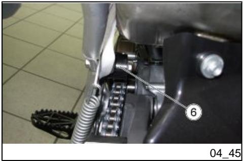
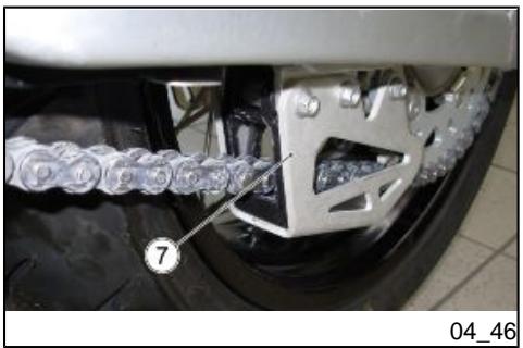
- Check chain roller, «6» the chain slide pad and chain tensioner pads «7» for wear.
- Also check the fork «8» protection pad for wear.
CAUTION
LUBRICATE THE CHAIN ON A REGULAR BASIS, PARTICULARLY IF YOU FIND DRY OR RUSTY PARTS. FLAT-TENED OR JAMMED CHAIN LINKS MUST LUBRICATED AND REPAIRED. IF REPAIR IS NOT POSSIBLE, CONTACT AN Official aprilia Dealer TO HAVE IT REPLACED.
Chain lubrication and cleaning
Lubricate the chain whenever necessary. Lubricate the chain with chain spray grease. Do not wash the chain with water jets, vapour jets, high-pressure water jets and highly flammable solvents.

BE EXTREMELY CAREFUL WHEN ADJUSTING, LUBRICATING, WASHING AND REPLACING THE CHAIN.
| Max. length | 2240 mm (88.19 in) |
| Max. width | 830 mm (32.68 in) |
| Max. height (to windshield) | 1250 mm (49.21 in) |
| Saddle height | 940 mm (37.01 in) |
| Wheelbase | 1485 mm (58.46 in) |
| Minimum ground clearance | 320 mm (12.60 in) |
| Kerb weight (of every fluid ) | 116.5 kg (256.84 lb) |
| Fuel tank capacity (including reserve) | 7.5 l (1.65 Ukgal) |
| Fuel reserve | 2.2 l (0.48 Ukgal) |
| Engine oil capacity | 1.3 l (0.28 Ukgal) |
| Fork oil capacity | 100 mm (3.94 in) of clearance (for each stem, measured without spring and under compression) |
| Coolant capacity | 1.1 l (0.24 Ukgal) (50% water + 50% antifreeze solution with ethylene glycol) |
| Seats | 1 |
| CHASSIS | Tubular steel perimeter frame and aluminium vertical members |
| Front suspension | hydraulic action telescopic fork, Ø 45 mm (Ø 1.77 in) stems |
TECHNISCHE GEGEVENS RXV 450 - RXV 550 (VOERTUIG)
| Max lenghte | 2240 mm (88.19 in) |
| Max bredte | 830 mm (32.68 in) |
| Max hoogte (tot de kap) | 1250 mm (49.21 in) |
| Hoogte tot het zadel | 940 mm (37.01 in) |
| Asafstand | 1485 mm (58.46 in) |
| Minimum vrij hoogte vanaf de grond | 320 mm (12.60 in) |
| Droog gewicht (zonder vloeistoffen) | 116,5 kg (256.84 lb) |
| Capaciteit van de brandstoftank (inclusief de reserve) | 7,5 l (1.65 Uk gal) |
| Brandstofreserve | 2,2 l (0.48 Uk gal) |
| Capaciteit van de motorolie | 1,3 l (0.28 Uk gal) |
| Capaciteit van de olie voor de vork | 100 mm (3.94 in) luckt (gemeten voor elke stang, zonder veer en met stang in compressie) |
| Capaciteit van de koelvloeistof | 1,1 l (0.24 gal) (50% water + 50% antivries met ethyleenglycol) |
| Plaatsen | 1 |
| FRAME | Stijl in aluminium, en raamwerk in stalen buizen |
| Front suspension travel | 298.5 mm (11.75 in) |
| Rear suspension | Oscillating fork and adjustable hydraulic single shock absorber |
| Rear wheel travel | 300 mm (11.81 in) (usable) |
| Front brake | Ø 270 mm (Ø 10.63 in) disc brake with hydraulic transmission |
| Rear brake | Ø 240 mm (Ø 9.45 in) disc brake with hydraulic transmission |
| Wheel rims | with spokes |
| Front wheel rim | 1.60 x 21 |
| Rear wheel rim | 2.15 x 18 |
| front tyre | 90/90 21 54R |
| Front tyre inflation pressure | 100 kPa (1.0 bar) |
| Rear tyre | 140/80 18 70R |
| Rear tyre inflation pressure | 110 kPa (1.1 bar) |
| Model | 45RX |
| Engine | 4-stroke, twin-cylinder, 4 valves per cylinder, single overhead camshaft |
| Model | 45RX |
| Motor | bicilindrisch 4-takt met 4 kleppen per cilinder, monoas met nokken in de kop |
| Number of cylinders | 2 |
| overall cylinder capacity | 449 cm3 (27.40 cu.in) |
| Bore / stroke | 76 mm / 49.5 mm (2.99 in / 1.95 in) |
| Compression ratio | 13 ± 0.5 |
| Ignition | electronic |
| Engine revs at idle speed | 1800 ÷ 2000 rpm |
| Clutch | multiple-disc oil-bathed clutch |
| Lubrication system | Separate twin-sump lubrication system with external reservoir |
| Air filter | Sponge |
| Cooling | Fluid |
| Gearbox | mechanical, 5 speeds with foot lever on the left hand side of the engine |
| Gear ratio | Primary: 22/56 = 1 : 2.545 Final: 15/50 = 1 : 3.200 |
| 1st | 12/31 = 1 : 2.583 (secondary) 1: 21.042 (total) |
| 2nd | 13/25 = 1 : 1.923 (secondary) 1: 15.664 (total) |
| 3rd | 15/23 = 1 : 1.533 (secondary) 1: 12.489 (total) |
| 4th | 19/24 = 1 : 1.263 (secondary) |
| 5th | 21/22 = 1 : 1.047 (secondary) 1: 8.533 (total) |
| Drive chain | with master link |
| Fuel system | electronic injection |
| Diffuser | Ø 38 mm (1.49 in) |
| Fuel supply | premium unleaded petrol, minimum octane rating of 95 (NORM) and 85 (NOMM) |
| Model | 55RX |
| Engine | 4-stroke, twin-cylinder, 4 valves per cylinder, single overhead camshaft |
| Number of cylinders | 2 |
| Overall engine capacity | 553 cm³ (33.75 cu.in) |
| Bore / stroke | 80 mm / 55.0 mm (3.15 in / 2.16 in) |
| Compression ratio | 12.5 ± 0.5 |
| Ignition | electronic |
| Engine revs at idle speed | 1800 ÷ 2000 rpm |
| Ignition | Electronic |
| Standard spark plug | NGK CR8EKB |
| Spark plug electrode gap | 0.7 ± 0.8 mm (0.028 in ± 0.031 in) |
| Resistance | 5 kΩ |
| Battery | 12V-6 Ah |
| Main fuse | 30 A |
| Auxiliary fuses | 5 A; 7.5 A; 15 A |
| (Permanent-magnet) Generator | 12V - 350W |
| Low-beam bulb | 12V - 55W |
| High-beam bulb | 12V - 60W |
| Front side light bulb | 12V - 3W |
| Turn indicator bulb | with micro-bulbs |
| License plate light bulb | 12V - 5W |
| Tail light/stop light bulb | LED |
| Neutral gear warning light | LED |
| Low fuel warning light | LED |
| High-beam warning light | LED |
ELEKTRISCHE ONDERDELEN
A toolkit is supplied with the vehicle and it contains:
- Pouch bag.
Reversible crosshead/blade screwdriver, 6× 128mm
Reversible screwdriver handle
16 x 50 mm box-spanner with 13 x 20 mm welded hex.
Double polygonal L-shaped wrench, 12 × 13 ~mm .
Spare parts and accessories
Hst. 06
RXV models are supplied with a number of accessories not installed:
- Stand safety band
- Plate holder/racing rear light
- Hand guards
CAUTION

DO NOT USE THE VEHICLE OFF ROAD WITH THE NUMBER PLATE HOLDER/REAR LIGHT APPROVED FOR ROAD USE.
Waarschuwingen
| Km x 1,000 | 0.5 | 3 | 6 | 9 | 12 | 15 | 18 | 21 | 24 | 27 | 30 |
| Throttle body assembly screw torque | I | I | I | I | I | I | I | I | I | I | I |
| Throttle bodies | A | A | A | A | A | A | A | A | A | A | A |
| Air filter and filter casing | I | I | I | I | I | I | I | I | I | I | I |
| Fuel piping | I | I | I | I | I | I | I | I | I | I | I |
| idle speed adjustment | A | A | A | A | A | A | A | A | A | A | A |
| Gearbox oil | R | R | R | R | R | R | R | R | R | R | R |
| Clutch springs | - | I | I | I | I | I | I | I | I | I | I |
| Clutch discs | - | I | I | I | I | I | I | I | I | I | I |
| Clutch control | I | I | I | I | I | I | I | I | I | I | I |
| Coolant level in radiator and expansion tank | I | I | I | I | I | I | I | I | I | I | I |
| System seals | - | I | I | I | I | I | I | I | I | I | I |
| Engine oil and engine oil filter | R | R | R | R | R | R | R | R | R | R | R |
| Fuel pipes | I | I | I | I | I | I | I | I | I | I | I |
| Throttle cables | A | A | A | A | A | A | A | A | A | A | A |
| Brake fluid level | I | I | I | I | I | I | I | I | I | I | I |
| Brakes pipes | I | I | I | I | I | I | I | I | I | I | I |
| Brake system screw torque | I | I | I | I | I | I | I | I | I | I | I |
| Brake discs thickness | - | I | I | I | I | I | I | I | I | I | I |
| Brake pads thickness | - | I | I | I | I | I | I | I | I | I | I |
| Electrical contacts and switches | - | I | I | I | I | I | I | I | I | I | I |
| Battery connections | - | I | I | I | I | I | I | I | I | I | I |
| Light operation/direction | A | A | A | A | A | A | A | A | A | A | A |
| Electrical system operation | I | I | I | I | I | I | I | I | I | I | I |
| Discharge | - | I | I | I | I | I | I | I | I | I | I |
| Tyre pressure and wear conditions | I | I | I | I | I | I | I | I | I | I | I |
| Wheel bearings | I | I | I | I | I | I | I | I | I | I | I |
| Wheel spokes and rim coaxiality | I | I | I | I | I | I | I | I | I | I | I |
| Tightening of wheel pin nuts and screws | I | I | I | I | I | I | I | I | I | I | I |
| Engine mounting screws torque | I | I | I | I | I | I | I | I | I | I | I |
| Tightening of chassis screws and nuts | I | I | I | I | I | I | I | I | I | I | I |
| Fork dust guards | - | C | C | C | C | C | C | C | C | C | C |
| Fork legs ** | - | I | I | I | I | I | I | I | I | I | I |
| Fork | I | I | I | I | I | I | I | I | I | I | I |
| Tightening of fork plates and feet screws | I | I | I | I | I | I | I | I | I | I | I |
| Shock absorber pins tightening | I | I | I | I | I | I | I | I | I | I | I |
| Shock absorber | I | I | I | I | I | I | I | I | I | I | I |
| Steering bearings clearance | I | I | I | I | I | I | I | I | I | I | I |
| Headstock dust guards | C | C | C | C | C | C | C | C | C | C | C |
| Drive chain | I | I | I | I | I | I | I | I | I | I | I |
| Chain link, chain sprocket and chain guide | I | I | I | I | I | I | I | I | I | I | I |
| Steering bearings | L | L | L | L | L | L | L | L | L | L | L |
| Clutch lever pin | - | L | L | L | L | L | L | L | L | L | L |
| Throttle cables | - | L | L | L | L | L | L | L | L | L | L |
| Rider footrest pins | - | L | L | L | L | L | L | L | L | L | L |
| Rear suspension linkage system | - | L | L | L | L | L | L | L | L | L | L |
| Side stand bolt | - | L | L | L | L | L | L | L | L | L | L |
| Front wheel bolt and bearings | - | L | L | L | L | L | L | L | L | L | L |
| Rear fork bolt | - | L | L | L | L | L | L | L | L | L | L |
| Rear wheel bolt and bearings | - | L | L | L | L | L | L | L | L | L | L |
| Sponge air filter | - | - | R | - | R | - | R | - | R | - | R |
| SPARK PLUGS | - | - | R | - | R | - | R | - | R | - | R |
| Complete gearbox | - | - | - | I | - | - | I | - | - | I | - |
| Pressure relief and non-return valve spring | - | - | - | I | - | - | I | - | - | I | - |
| Cylinder liners | - | - | - | I | - | - | I | - | - | I | - |
| Connecting rod and main bushings | - | - | - | I | - | - | I | - | - | I | - |
| Start-up gears | - | - | - | I | - | - | I | - | - | I | - |
| Oil pump gears | - | - | - | I | - | - | I | - | - | I | - |
| Head lubrication nozzles | - | - | - | C | - | - | C | - | - | C | - |
| Pistons and piston rings | - | - | - | R | - | - | R | - | - | R | - |
| Piston pin | - | - | - | I | - | - | I | - | - | I | - |
| Rocking lever rollers | - | - | - | I | - | - | I | - | - | I | - |
| Valve lifter | - | - | - | I | - | - | I | - | - | I | - |
| Camshaft wear | - | - | - | I | - | - | I | - | - | I | - |
| Camshaft bearings | - | - | - | I | - | - | I | - | - | I | - |
| Valve seat sealing | - | - | - | I | - | - | I | - | - | I | - |
| Valves | - | - | - | I | - | - | I | - | - | I | - |
| Valve clearance | - | - | - | A | - | - | A | - | - | A | - |
| Valve guides | - | - | - | I | - | - | I | - | - | I | - |
| Spring washers, caps, bowls | - | - | - | I | - | - | I | - | - | I | - |
| Chain tensioner tothing | - | - | - | I | - | - | I | - | - | I | - |
| Valve springs | - | - | - | I | - | - | I | - | - | I | - |
| Timing system chain | - | - | - | I | - | - | I | - | - | I | - |
| Drive chain sliders | - | - | - | I | - | - | I | - | - | I | - |
| Fuel pump | - | - | - | I | - | - | I | - | - | I | - |
| Fork (comprehensive maintenance) | - | - | - | I | - | - | I | - | - | I | - |
| Fork oil | - | - | - | R | - | - | R | - | - | R | - |
| Shock absorber (comprehensive maintenance) | - | - | - | I | - | - | I | - | - | I | - |
| Crankshaft and connecting rod bearing clearance | - | - | - | I | - | - | I | - | - | I | - |
| Chain guide slider | - | - | - | I | - | - | I | - | - | I | - |
| Chain guide eye | - | - | - | I | - | - | I | - | - | I | - |
| Chain tensioner roller | - | - | - | I | - | - | I | - | - | I | - |
| Chain tensioner pad | - | - | - | I | - | - | I | - | - | I | - |
| Brake fluid *** | - | - | - | - | - | - | - | - | - | - | - |
I: INSPECT AND CLEAN, ADJUST, LUBRICATE OR REPLACE IF NECESSARY
C: CLEAN, R: REPLACE, A: ADJUST, L: LUBRICATE
End of run-in
* Carry out bleeding
***Replace every year
KAART VAN HET PERIODIEK ONDERHOUD VOOR VOERTUIGEN IN DE ORIGINELE VERSIE (VERMINDERD VERMOGEN) VOOR WEGGBRUIK.
| Hours of operation | 3 | 15 | 30 | 45 | 60 | 75 | 90 | 105 | 120 | 135 | 150 |
| Throttle body assembly screw torque | I | I | I | I | I | I | I | I | I | I | I |
| Throttle bodies | A | A | A | A | A | A | A | A | A | A | A |
| Air filter and filter casing | I | I | I | I | I | I | I | I | I | I | I |
| Fuel piping | I | I | I | I | I | I | I | I | I | I | I |
| idle speed adjustment | A | A | A | A | A | A | A | A | A | A | A |
| Gearbox oil | R | R | R | R | R | R | R | R | R | R | R |
| Clutch springs | - | I | I | I | I | I | I | I | I | I | I |
| Clutch discs | - | I | I | I | I | I | I | I | I | I | I |
| Clutch control | I | I | I | I | I | I | I | I | I | I | I |
| Coolant level in radiator and expansion tank | I | I | I | I | I | I | I | I | I | I | I |
| System seals | - | I | I | I | I | I | I | I | I | I | I |
| Engine oil and engine oil filter | R | R | R | R | R | R | R | R | R | R | R |
| Fuel pipes | I | I | I | I | I | I | I | I | I | I | I |
| Throttle cables | A | A | A | A | A | A | A | A | A | A | A |
| Brake fluid level | I | I | I | I | I | I | I | I | I | I | I |
| Brakes pipes | I | I | I | I | I | I | I | I | I | I | I |
| Brake system screw torque | I | I | I | I | I | I | I | I | I | I | I |
| Brake discs thickness | - | I | I | I | I | I | I | I | I | I | I |
| Brake pads thickness | - | I | I | I | I | I | I | I | I | I | I |
| Electrical contacts and switches | - | I | I | I | I | I | I | I | I | I | I |
| Battery connections | - | I | I | I | I | I | I | I | I | I | I |
| Light operation/direction | A | A | A | A | A | A | A | A | A | A | A |
| Electrical system operation | I | I | I | I | I | I | I | I | I | I | I |
| Discharge | - | I | I | I | I | I | I | I | I | I | I |
| Tyre pressure and wear conditions | I | I | I | I | I | I | I | I | I | I | I |
| Wheel bearings | I | I | I | I | I | I | I | I | I | I | I |
| Wheel spokes and rim coaxiality | I | I | I | I | I | I | I | I | I | I | I |
| Tightening of wheel pin nuts and screws | I | I | I | I | I | I | I | I | I | I | I |
| Engine mounting screws torque | I | I | I | I | I | I | I | I | I | I | I |
| Tightening of chassis screws and nuts | I | I | I | I | I | I | I | I | I | I | I |
| Fork dust guards | - | C | C | C | C | C | C | C | C | C | C |
| Fork legs ** | - | I | I | I | I | I | I | I | I | I | I |
| Fork | I | I | I | I | I | I | I | I | I | I | I |
| Tightening of fork plates and feet screws | I | I | I | I | I | I | I | I | I | I | I |
| Shock absorber pins tightening | I | I | I | I | I | I | I | I | I | I | I |
| Shock absorber | I | I | I | I | I | I | I | I | I | I | I |
| Steering bearings clearance | I | I | I | I | I | I | I | I | I | I | I |
| Headstock dust guards | C | C | C | C | C | C | C | C | C | C | C |
| Drive chain | I | I | I | I | I | I | I | I | I | I | I |
| Chain link, chain sprocket and chain guide | I | I | I | I | I | I | I | I | I | I | I |
| Steering bearings | L | L | L | L | L | L | L | L | L | L | L |
| Clutch lever pin | - | L | L | L | L | L | L | L | L | L | L |
| Throttle cables | - | L | L | L | L | L | L | L | L | L | L |
| Rider footrest pins | - | L | L | L | L | L | L | L | L | L | L |
| Rear suspension linkage system | - | L | L | L | L | L | L | L | L | L | L |
| Side stand bolt | - | L | L | L | L | L | L | L | L | L | L |
| Front wheel bolt and bearings | - | L | L | L | L | L | L | L | L | L | L |
| Rear fork bolt | - | L | L | L | L | L | L | L | L | L | L |
| Rear wheel bolt and bearings | - | L | L | L | L | L | L | L | L | L | L |
| Sponge air filter | - | - | - | - | R | - | - | - | R | - | - |
| SPARK PLUGS | - | - | - | - | R | - | - | - | R | - | - |
| Complete gearbox | - | - | - | - | - | - | I | - | - | - | - |
| Pressure relief and non-return valve spring | - | - | - | - | - | - | I | - | - | - | - |
| Cylinder liners | - | - | - | - | - | - | I | - | - | - | - |
| Connecting rod and main bushings | - | - | - | - | - | - | I | - | - | - | - |
| Start-up gears | - | - | - | - | - | - | I | - | - | - | - |
| Oil pump gears | - | - | - | - | - | - | I | - | - | - | - |
| Head lubrication nozzles | - | - | - | - | - | - | C | - | - | - | - |
| Pistons and piston rings | - | - | - | - | - | - | R | - | - | - | - |
| Piston pin | - | - | - | - | - | - | I | - | - | - | - |
| Rocking lever rollers | - | - | - | - | - | - | I | - | - | - | - |
| Valve lifter | - | - | - | - | - | - | I | - | - | - | - |
| Camshaft wear | - | - | - | - | - | - | I | - | - | - | - |
| Camshaft bearings | - | - | - | - | - | - | I | - | - | - | - |
| Valve seat sealing | - | - | - | - | - | - | I | - | - | - | - |
| Valves | - | - | - | - | - | - | I | - | - | - | - |
| Valve clearance | - | - | - | - | - | - | A | - | - | - | - |
| Valve guides | - | - | - | - | - | - | I | - | - | - | - |
| Spring washers, caps, bowls | - | - | - | - | - | - | I | - | - | - | - |
| Chain tensioner totoing | - | - | - | - | - | - | I | - | - | - | - |
| Valve springs | - | - | - | - | - | - | I | - | - | - | - |
| Timing system chain | - | - | - | - | - | - | I | - | - | - | - |
| Drive chain sliders | - | - | - | - | - | - | I | - | - | - | - |
| Fuel pump | - | - | - | - | - | - | I | - | - | - | - |
| Fork (comprehensive maintenance) | - | - | - | - | - | - | I | - | - | - | - |
| Fork oil | - | - | - | - | - | - | R | - | - | - | - |
| Shock absorber (comprehensive maintenance) | - | - | - | - | - | - | I | - | - | - | - |
| Crankshaft and connecting rod bearing clearance | - | - | - | - | - | - | I | - | - | - | - |
| Chain guide slider | - | - | - | - | - | - | I | - | - | - | - |
| Chain guide eye | - | - | - | - | - | - | I | - | - | - | - |
| Chain tensioner roller | - | - | - | - | - | - | I | - | - | - | - |
| Chain tensioner pad | - | - | - | - | - | - | I | - | - | - | - |
| Brake fluid *** | - | - | - | - | - | - | - | - | - | - | - |
I: INSPECT AND CLEAN, ADJUST, LUBRICATE OR REPLACE IF NECESSARY
C: CLEAN, R: REPLACE, A: ADJUST, L: LUBRICATE
- End of run-in
** Carry out bleeding
*** Replace every year
KAART VAN HET PERIODIEK ONDERHOUD VOOR VOERTUIGEN IN VRIJE VERSIE VOOR SPORTIEF- EN HOBBYGEBRUIK.
| Hours of operation | 3 | 15 | 30 | 45 | 60 | 75 | 90 | 105 | 120 | 135 | 150 |
| Throttle body assembly screw torque | I | I | I | I | I | I | I | I | I | I | I |
| Throttle bodies | A | A | A | A | A | A | A | A | A | A | A |
| Air filter and filter casing | I | I | I | I | I | I | I | I | I | I | I |
| Fuel piping | I | I | I | I | I | I | I | I | I | I | I |
| idle speed adjustment | A | A | A | A | A | A | A | A | A | A | A |
| Gearbox oil | R | R | R | R | R | R | R | R | R | R | R |
| Clutch springs | - | I | I | I | I | I | I | I | I | I | I |
| Clutch discs | - | I | I | I | I | I | I | I | I | I | I |
| Clutch control | I | I | I | I | I | I | I | I | I | I | I |
| Coolant level in radiator and expansion tank | I | I | I | I | I | I | I | I | I | I | I |
| System seals | - | I | I | I | I | I | I | I | I | I | I |
| Engine oil and engine oil filter | R | R | R | R | R | R | R | R | R | R | R |
| Fuel pipes | I | I | I | I | I | I | I | I | I | I | I |
| Throttle cables | A | A | A | A | A | A | A | A | A | A | A |
| Brake fluid level | I | I | I | I | I | I | I | I | I | I | I |
| Brakes pipes | I | I | I | I | I | I | I | I | I | I | I |
| Brake system screw torque | I | I | I | I | I | I | I | I | I | I | I |
| Brake discs thickness | - | I | I | I | I | I | I | I | I | I | I |
| Brake pads thickness | - | I | I | I | I | I | I | I | I | I | I |
| Electrical contacts and switches | - | I | I | I | I | I | I | I | I | I | I |
| Battery connections | - | I | I | I | I | I | I | I | I | I | I |
| Light operation/direction | A | A | A | A | A | A | A | A | A | A | A |
| Electrical system operation | I | I | I | I | I | I | I | I | I | I | I |
| Discharge | - | I | I | I | I | I | I | I | I | I | I |
| Tyre pressure and wear conditions | I | I | I | I | I | I | I | I | I | I | I |
| Wheel bearings | I | I | I | I | I | I | I | I | I | I | I |
| Wheel spokes and rim coaxiality | I | I | I | I | I | I | I | I | I | I | I |
| Tightening of wheel pin nuts and screws | I | I | I | I | I | I | I | I | I | I | I |
| Engine mounting screws torque | I | I | I | I | I | I | I | I | I | I | I |
| Tightening of chassis screws and nuts | I | I | I | I | I | I | I | I | I | I | I |
| Fork dust guards | - | C | C | C | C | C | C | C | C | C | C |
| Fork legs ** | - | I | I | I | I | I | I | I | I | I | I |
| Fork | I | I | I | I | I | I | I | I | I | I | I |
| Tightening of fork plates and feet screws | I | I | I | I | I | I | I | I | I | I | I |
| Shock absorber pins tightening | I | I | I | I | I | I | I | I | I | I | I |
| Shock absorber | I | I | I | I | I | I | I | I | I | I | I |
| Steering bearings clearance | I | I | I | I | I | I | I | I | I | I | I |
| Headstock dust guards | C | C | C | C | C | C | C | C | C | C | C |
| Drive chain | I | I | I | I | I | I | I | I | I | I | I |
| Chain link, chain sprocket and chain guide | I | I | I | I | I | I | I | I | I | I | I |
| Steering bearings | L | L | L | L | L | L | L | L | L | L | L |
| Clutch lever pin | - | L | L | L | L | L | L | L | L | L | L |
| Throttle cables | - | L | L | L | L | L | L | L | L | L | L |
| Rider footrest pins | - | L | L | L | L | L | L | L | L | L | L |
| Rear suspension linkage system | - | L | L | L | L | L | L | L | L | L | L |
| Side stand bolt | - | L | L | L | L | L | L | L | L | L | L |
| Front wheel bolt and bearings | - | L | L | L | L | L | L | L | L | L | L |
| Rear fork bolt | - | L | L | L | L | L | L | L | L | L | L |
| Rear wheel bolt and bearings | - | L | L | L | L | L | L | L | L | L | L |
| Sponge air filter | - | - | - | R | - | - | - | R | - | - | - |
| SPARK PLUGS | - | - | - | R | - | - | - | R | - | - | - |
| Complete gearbox | - | - | - | - | - | I | - | - | - | - | - |
| Pressure relief and non-return valve spring | - | - | - | - | - | I | - | - | - | - | - |
| Cylinder liners | - | - | - | - | - | I | - | - | - | - | - |
| Connecting rod and main bushings | - | - | - | - | - | I | - | - | - | - | - |
| Start-up gears | - | - | - | - | - | I | - | - | - | - | - |
| Oil pump gears | - | - | - | - | - | I | - | - | - | - | - |
| Head lubrication nozzles | - | - | - | - | - | C | - | - | - | - | - |
| Pistons and piston rings | - | - | - | - | - | R | - | - | - | - | - |
| Piston pin | - | - | - | - | - | I | - | - | - | - | - |
| Rocking lever rollers | - | - | - | - | - | I | - | - | - | - | - |
| Valve lifter | - | - | - | - | - | I | - | - | - | - | - |
| Camshaft wear | - | - | - | - | - | I | - | - | - | - | - |
| Camshaft bearings | - | - | - | - | - | I | - | - | - | - | - |
| Valve seat sealing | - | - | - | - | - | I | - | - | - | - | - |
| Valves | - | - | - | - | - | I | - | - | - | - | - |
| Valve clearance | - | - | - | - | - | A | - | - | - | - | - |
| Valve guides | - | - | - | - | - | I | - | - | - | - | - |
| Spring washers, caps, bowls | - | - | - | - | - | I | - | - | - | - | - |
| Chain tensioner totothing | - | - | - | - | - | I | - | - | - | - | - |
| Valve springs | - | - | - | - | - | I | - | - | - | - | - |
| Timing system chain | - | - | - | - | - | I | - | - | - | - | - |
| Drive chain sliders | - | - | - | - | - | I | - | - | - | - | - |
| Fuel pump | - | - | - | - | - | I | - | - | - | - | - |
| Fork (comprehensive maintenance) | - | - | - | - | - | I | - | - | - | - | - |
| Fork oil | - | - | - | - | - | R | - | - | - | - | - |
| Shock absorber (comprehensive maintenance) | - | - | - | - | - | I | - | - | - | - | - |
| Crankshaft and connecting rod bearing clearance | - | - | - | - | - | I | - | - | - | - | - |
| Chain guide slider | - | - | - | - | - | I | - | - | - | - | - |
| Chain guide eye | - | - | - | - | - | I | - | - | - | - | - |
| Chain tensioner roller | - | - | - | - | - | I | - | - | - | - | - |
| Chain tensioner pad | - | - | - | - | - | I | - | - | - | - | - |
| Brake fluid *** | - | - | - | - | - | - | - | - | - | - | - |
I: INSPECT AND CLEAN, ADJUST, LUBRICATE OR REPLACE IF NECESSARY
C: CLEAN, R: REPLACE, A: ADJUST, L: LUBRICATE
End of run-in
* Carry out bleeding
*** Replace every year
KAART VAN HET PERIODIEK ONDERHOUD VOOR VOERTUIGEN IN VRIJE VERSIE VOOR WEDSTRIJDGEBRUIK.
IF THE VEHICLE IS USED FOR COMPETITIONS, CARRY OUT THE 15-HOUR SERVICE AFTER EVERY RACE.
NOTE
- MAINTENANCE OPERATIONS BY THE SPECIALISED APRILIA WORKSHOP DO NOT REPLACE DAILY CHECKING BY THE RIDER!
LET OP
WANNEER MEN HET VOERTUIG COMPETITIEGERICHT GEBRUIKT, MOET DE SERVICEBEURT VAN NA 15 GEBRUKSUREN NA ELKE WEDSTRIJD WORDEN UITGEVOERD.
N.B.
-
DE ONDERHOUDSHANDELINGEN
VAN DE GESPECIALISEERDE APRI -
IF DISTORTIONS, DAMAGES OR WEAR EXCEEDING THE TOLERATED VALUES ARE FOUND, REPLACE THE INVOLVED COMPONENTS
-
BEFORE CARRYING OUT ANY OPERATION, CLEAN YOUR VEHICLE CAREFULLY
-
RIDING ON SANDY OR DUSTY ROADS OR UNDER EXTREME SITUATIONS MAY WEAR DOWN SOME COMPONENTS EVEN BEFORE THE SCHEDULED CHECK.
IF THE VEHICLE IS USED MAINLY FOR MOTOCROSS RACING, CARRY OUT ALL THE MAINTENANCE SERVICES INDICATED IN THE 75-HOUR COLUMN EVERY 50 HOURS OF USE.
LIA GARAGE VERVANGEN DE DAGELIJKSE CONTROLE VAN DE BESTUURDER NIET!
-
WANNEER BIJ DE CONTROLE SLIJTAGE WORDT OPGEMERKT, NAAST TOLERANTIEWAARDEN, VERVORMING OF SCHADE, MOETEN DE GEINTERESSEERDE ONDERDELEN VERVANGEN WORDEN
-
VOORALEER MEN EENDER WELKE HANDELING UITVOERT, MOET HET VOERTUIG NAUWGEZET GEREINIGD WORDEN
-
HET GEBRUK VAN HET VOERTUIG OP ZANDERIGE OF STOFFIGE WEGEN EN IN EXTREME GEBRUKSCONDITIES, ZOU DE SLIJTAGE KUNNEN VEROORZAKEN VAN SOMMIGE ONDERDELEN VOOR DE GEPROGRAMMERDE CONTROLLE.
-
WANNEER HET VOERTUIG VOORNAMELIJK WORDT GEBRUIKT VOOR HET CROSSEN, MOET MEN ELKE 50 GEBRUKSUREN ALLE VOORZIENE ONDERHOUDSHANDELINGEN UITVOEREN VOOR NA 75 GEBRUKSUREN.
RECOMMENDED PRODUCTS TABLE
| Product | Description | Specifications |
| AGIP RACING 4T 10W-60 | Engine oil | Use top-branded oils that meet or exceed the requirements of CCMC G-4 API SG, SAE 10W-60 specifications. |
| AGIP RACING 4T 10W-60 | Gearbox oil | - |
| SPECIAL AGIP PERMANENT fluid | Coolant | Ready for use mixed biodegradable coolant with "long life" technology and characteristics (red). Freezing protection up to -40°C. In compliance with the CUNA 956-16 standard. |
| AGIP BRAKE 4 | Brake fluid | As an alternative to the recommended fluid, other fluids that meet or exceed the required specifications may be used. SAE J1703, NHTSA 116 DOT 4, ISO 4925 Synthetic fluid |
| AGIP MP GREASE | Grease for bearings, joints, couplings and leverages | As an alternative to the recommended product, use top-branded grease for roller bearings with an operating temperature range of -30°C...+140°C (-22°F...+284°F), a drop point of 150° C...230°C (302°F...446°F), high corrosion protection qualities and good water and rust resistance. |
| AGIP FORK 7.5W | Fork oil | SAE 7.5W |
LABEL MET AANBEVOLEN PRODUCTEN
Engine oil: 13, 72, 75
Engine stop: 38
F
Fork: 53
Fuel: 10
Fuses: 103
G
Gearbox oil: 13, 77
H
Headlight: 109
Horn: 36
1
Identification: 39
Instrument panel: 28
M
Maintenance: 71, 137, 138
s
Saddle: 39
Scheduled maintenance:
138
Shock absorbers: 49
Spark plug: 81
Stand: 63
Start-up: 37
T
Technical data: 127
Transmission: 120
TREFWOORDENREGISTER
A
Accessoires: 135
ACCU: 14, 102
K
Ketting: 121-123, 125
Koelvloeistof:11,88
Koplamp: 109
s
Schijfrem: 110
Standaard: 63
Stuurslot: 35
B
BOUGIE:81
Brandstof: 10
L
Luchtfilter: 86
T
As a result of continuous technical updates and specific mechanic training programs for aprilia products, only aprilia Official Network mechanics know this vehicle fully and have the special tools necessary to carry out maintenance and repair operations correctly.
The reliability of the vehicle also depends on its mechanical state. Checking the vehicle before riding, its regular maintenance and using only Original aprilia Spare Parts are essential!
For information about the nearest Official Dealer and/or Service Centre, consult the Yellow Pages or search directly on the inset map in our Official Website:
www.aprilia.com
Only by requesting aprilia Original Spare Parts can you be sure of purchasing products that were developed and tested during the actual vehicle design stage. All aprilia Original Spare Parts undergo quality control procedures to guarantee reliability and durability.
The descriptions and illustrations given in this publication are not binding; While the basic characteristics as described and illustrated in this booklet remain unchanged, aprilia reserves the right, at any time and without being required to update this publication beforehand, to make any changes to components, parts or accessories, which it considers necessary to improve the product or which are required for manufacturing or construction reasons.
Not all versions/models shown in this publication are available in all Countries. The availability of individual versions/models should be confirmed with the official aprilia sales network.
Copyright 2008- aprilia. All rights reserved. Reproduction of this publication in whole or in part is prohibited. aprilia - After sales service.
The aprilia trademark is property of Piaggio & C. S.p.A.