
1902 - Electric planer MAKITA - Free user manual and instructions
Find the device manual for free 1902 MAKITA in PDF.

| Product type | Electric planer |
| Brand | Makita |
| Model | 1902 |
| Planing width | 82 mm (3-1/4") |
| Maximum planing depth | 1 mm (1/32") |
| Rabbet depth | 9 mm (11/32") |
| No load speed | 16,000 rpm |
| Overall length | 290 mm (11-3/8") |
| Net weight | 2.5 kg (5.5 lbs) |
| Insulation | Double insulation (Class II) |
| Power supply | 120 V~ (depending on model), 50/60 Hz |
| Switch | Trigger switch with lock button for continuous operation |
| Depth adjustment | By knob on the front of the tool |
| Chip discharge | Through rear opening, can be connected to a dust nozzle assembly (optional) |
| Planer blades | Two interchangeable blades (steel or carbide-tipped optional) |
| Included accessories | Wrench, side guide, blade gauge |
| Maintenance | Carbon brush replacement, sharpening or replacement of blades |
| Warranty | 1 year against manufacturing defects |
Frequently Asked Questions - 1902 MAKITA
User questions about 1902 MAKITA
0 question about this device. Answer the ones you know or ask your own.
Ask a new question about this device
Download the instructions for your Electric planer in PDF format for free! Find your manual 1902 - MAKITA and take your electronic device back in hand. On this page are published all the documents necessary for the use of your device. 1902 by MAKITA.
USER MANUAL 1902 MAKITA
MANUEL D'INSTRUCTION
For your personal safety, READ and UNDERSTAND before using.
SAVE THESE INSTRUCTIONS FOR FUTURE REFERENCE.
AVERTISSEMENT:
| Model | 1902 |
| Planing width | 82 mm (3-1/4") |
| Planing depth | 1 mm (1/32") |
| Shiplapping depth | 9 mm (11/32") |
| No load speed (RPM) | 16,000/min. |
| Overall length | 290 mm (11-3/8") |
| Net weight | 2.5 kg (5.5 lbs) |
- Due to our continuing programme of research and development, the specifications herein are subject to change without notice.
Note: Specifications may differ from country to country.
GENERAL SAFETY RULES
USA002-2
(For All Tools)
WARNING:
Read and understand all instructions. Failure to follow all instructions listed below, may result in electric shock, fire and/or serious personal injury.
SAVE THESE INSTRUCTIONS
Work Area
- Keep your work area clean and well lit. Cluttered benches and dark areas invite accidents.
- Do not operate power tools in explosive atmospheres, such as in the presence of flammable liquids, gases, or dust. Power tools create sparks which may ignite the dust or fumes.
- Keep bystanders, children, and visitors away while operating a power tool. Distractions can cause you to lose control.
Electrical Safety
- Double insulated tools are equipped with a polarized plug (one blade is wider than the other.) This plug will fit in a polarized outlet only one way. If the plug does not fit fully in the outlet, reverse the plug. If it still does not fit, contact a qualified electrician to install a polarized outlet. Do not change the plug in any way. Double insulation eliminates the need for the three wire grounded power cord and grounded power supply system.
- Avoid body contact with grounded surfaces such as pipes, radiators, ranges and refrigerera
tors. There is an increased risk of electric shock if your body is grounded.
- Do not expose power tools to rain or wet conditions. Water entering a power tool will increase the risk of electric shock.
- Do not abuse the cord. Never use the cord to carry the tools or pull the plug from an outlet. Keep cord away from heat, oil, sharp edges or moving parts. Replace damaged cords immediately. Damaged cords increase the risk of electric shock.
- When operating a power tool outside, use an outdoor extension cord marked "W-A" or "W". These cords are rated for outdoor use and reduce the risk of electric shock.
Personal Safety
- Stay alert, watch what you are doing and use common sense when operating a power tool. Do not use tool while tired or under the influence of drugs, alcohol, or medication. A moment of inattention while operating power tools may result in serious personal injury.
- Dress properly. Do not wear loose clothing or jewelry. Contain long hair. Keep your hair, clothing, and gloves away from moving parts. Loose clothes, jewelry, or long hair can be caught in moving parts.
- Avoid accidental starting. Be sure switch is off before plugging in. Carrying tools with your finger on the switch or plugging in tools that have the switch on invites accidents.
- Remove adjusting keys or wrenches before turning the tool on. A wrench or a key that is left attached to a rotating part of the tool may result in personal injury.
-
Do not overreach. Keep proper footing and balance at all times. Proper footing and balance enables better control of the tool in unexpected situations.
-
Use safety equipment. Always wear eye protection. Dust mask, non-skid safety shoes, hard hat, or hearing protection must be used for appropriate conditions. Ordinary eye or sun glasses are NOT eye protection.
Tool Use and Care
- Use clamps or other practical way to secure and support the workpiece to a stable platform. Holding the work by hand or against your body is unstable and may lead to loss of control.
- Do not force tool. Use the correct tool for your application. The correct tool will do the job better and safer at the rate for which it is designed.
- Do not use tool if switch does not turn it on or off. Any tool that cannot be controlled with the switch is dangerous and must be repaired.
- Disconnect the plug from the power source before making any adjustments, changing accessories, or storing the tool. Such preventive safety measures reduce the risk of starting the tool accidentally.
- Store idle tools out of reach of children and other untrained persons. Tools are dangerous in the hands of untrained users.
-
Maintain tools with care. Keep cutting tools sharp and clean. Properly maintained tools with sharp cutting edges are less likely to bind and are easier to control.
-
Check for misalignment or binding of moving parts, breakage of parts, and any other condition that may affect the tools operation. If damaged, have the tool serviced before using. Many accidents are caused by poorly maintained tools.
- Use only accessories that are recommended by the manufacturer for your model. Accessories that may be suitable for one tool, may become hazardous when used on another tool.
SERVICE
- Tool service must be performed only by qualified repair personnel. Service or maintenance performed by unqualified personnel could result in a risk of injury.
- When servicing a tool, use only identical replacement parts. Follow instructions in the Maintenance section of this manual. Use of unauthorized parts or failure to follow Maintenance instructions may create a risk of electric shock or injury.
USE PROPER EXTENSION CORD: Make sure your extension cord is in good condition. When using an extension cord, be sure to use one heavy enough to carry the current your product will draw. An undersized cord will cause a drop in line voltage resulting in loss of power and overheating. Table 1 shows the correct size to use depending on cord length and nameplate ampere rating. If in doubt, use the next heavier gage. The smaller the gage number, the heavier the cord.
Table 1. Minimum gage for cord
| Ampere Rating | Volts | Total length of cord in feet | ||||
| 120 V | 25 ft. | 50 ft. | 100 ft. | 150 ft. | ||
| More Than | Not More Than | AWG | ||||
| 0 | 6 | 18 | 16 | 16 | 14 | |
| 6 | 10 | 18 | 16 | 14 | 12 | |
| 10 | 12 | 16 | 16 | 14 | 12 | |
| 12 | 16 | 14 | 12 | Not Recommended | ||
SPECIFIC SAFETY RULES
USB042-2
DO NOT let comfort or familiarity with product (gained from repeated use) replace strict adherence to planer safety rules. If you use this tool unsafely or incorrectly, you can suffer serious personal injury.
- Rags, cloth, cord, string and the like should never be left around the work area.
-
Avoid cutting nails. Inspect for and remove all nails from the workpiece before operation.
-
Use only sharp blades. Handle the blades very carefully.
- Be sure the blade installation bolts are securely tightened before operation.
- Hold the tool firmly with both hands.
- Keep hands away from rotating parts.
- Before using the tool on an actual workpiece, let it run for a while. Watch for vibration or wobbling that could indicate poor installation or a poorly balanced blade.
- Make sure the blade is not contacting the workpiece before the switch is turned on.
-
Wait until the blade attains full speed before cutting.
-
Keep at least 200mm (8") away from the tool at all times.
- Always switch off and wait for the blades to come to a complete stop before any adjusting.
- Never stick your finger into the chip chute. Chute may jam when cutting damp wood. Clean out chips with a stick.
- Do not leave the tool running. Operate the tool only when hand-held.
- When leaving the planer, switch off and set it with the front base up on a wooden block, so that the blades do not contact anything.
- Always change both blades or covers on the drum, otherwise the resulting imbalance will cause vibration and shorten tool life.
- Wait for complete run-down before putting the tool aside.
- Use only Makita blades specified in this manual.
- Some material contains chemicals which may be toxic. Take caution to prevent dust inhalation and skin contact. Follow material supplier safety data.
SAVE THESE INSTRUCTIONS
WARNING:
MISUSE or failure to follow the safety rules stated in this instruction manual may cause serious personal injury.
SYMBOLS
USD201-2
The followings show the symbols used for tool.
V. .volts
A . amperes
Hz.....hertz
...alternating current
no load speed
Class II Construction
.../min.......revolutions or reciprocation per minute
FUNCTIONAL DESCRIPTION
CAUTION:
Always be sure that the tool is switched off and unplugged before adjusting or checking function on the tool.
Adjusting depth of cut
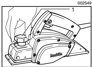
- Knob
Depth of cut may be adjusted by simply turning the knob on the front of the tool.
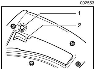
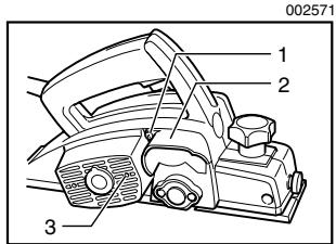
Switch action
-
Lock button
-
Switch trigger
CAUTION:
- Before plugging in the tool, always check to see that the switch trigger actuates properly and returns to the "OFF" position when released.
- Switch can be locked in "ON" position for ease of operator comfort during extended use. Apply caution when locking tool in "ON" position and maintain firm grasp on tool.
To start the tool, simply pull the switch trigger. Release the switch trigger to stop.
For continuous operation, pull the switch trigger and then push in the lock button.
To stop the tool from the locked position, pull the switch trigger fully, then release it.
ASSEMBLY
CAUTION:
Always be sure that the tool is switched off and unplugged before carrying out any work on the tool.
Removing or installing planer blades
CAUTION:
-
Tighten the blade installation bolts carefully when attaching the blades to the tool. A loose installation bolt can be dangerous. Always check to see they are tightened securely.
-
Handle the blades very carefully. Use gloves or rags to protect your fingers or hands when removing or installing the blades.
- Use only the Makita wrench provided to remove or install the blades. Failure to do so may result in overtightening or insufficient tightening of the installation bolts. This could cause an injury.
- Remove the existing blade, if the tool has been in use, carefully clean the drum surfaces and the drum cover. To remove the blades on the drum, unscrew the three installation bolts with the socket wrench. The drum cover comes off together with the blades.
- Socket wrench
-
Bolt
-
To install the blades, loosely attach the adjusting plate to the set plate with the pan head screws and set the mini planer blade on the gauge base so that the cutting edge of the blade is perfectly flush with the inside flank of the gauge plate.
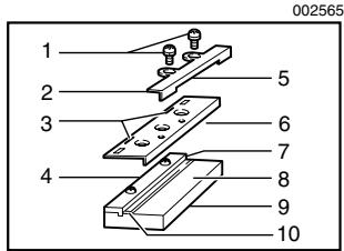
- Pan head screw
- Adjusting plate
- Planer blade locating lugs
- Gauge plate
- Heel of adjusting plate
- Set plate
- Inside flank of gauge plate
- Gauge base
- Back side of gauge base
-
Mini planer blade
-
Set the adjusting plate/set plate on the gauge base so that the planer blade locating lugs on the set plate rest in the mini planer blade groove, then press in the heel of the adjusting plate flush with the back side of the gauge base and tighten the pan head screws.
-
It is important that the blade sits flush with the inside flank of the gauge plate, the planer blade locating lugs sit in the blade groove and the heel of the adjusting plate is flush with the back side of the gauge base. Check this alignment carefully to ensure uniform cutting.
-
Slip the heel of the adjusting plate into the groove of the drum.
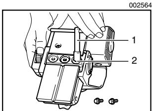
- Set the drum cover over the adjusting plate/set plate and screw in the three hex flange head bolts so that a gap exists between the drum and the set plate to slide the mini planer blade into position. The blade will be positioned by the planer blade locating lugs on the set plate.
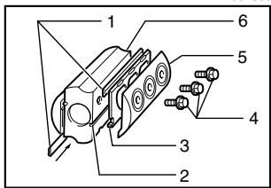
002566
- Mini planer blade
- Groove
- Set plate
- Hex. flange head bolt
-
Drum plate
6.Drum -
The blade's lengthwise adjustment will need to be manually positioned so that the blade ends are clear and equidistant from the housing on one side and the metal bracket on the other.
- Tighten the three hex flange head bolts (with the socket wrench provided) and hand rotate the drum to check clearances between the blade ends and the tool body.
- Check the three hex flange head bolts for final tightness.
- Repeat procedures 1 - 9 for other blade.
For the correct planer blade setting
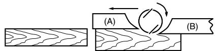
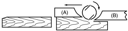
Your planing surface will end up rough and uneven, unless the blade is set properly and securely. The blade must be mounted so that the cutting edge is absolutely level, that is, parallel to the surface of the rear base.
Below are some examples of proper and improper settings.
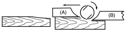
(A) Front base (Movable shoe)
(B) Rear base (Stationary shoe)
EN0004-1
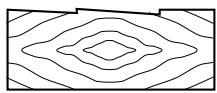
Correct setting
Although this side view cannot show it, the edges of the blades run perfectly parallel to the rear base surface.
Nicks in surface
Cause: One or both blades fails to have edge parallel to rear base line.
Gouging at start
Cause: One or both blade edges fails to protrude enough in relation to rear base line.
Gouging at end
Cause: One or both blade edges protrudes too far in relation to rear base line.
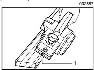
Nozzle assembly (optional accessory)
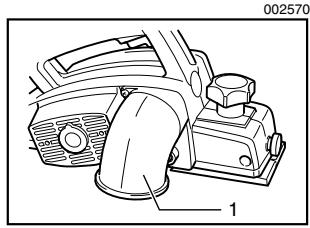
1. Nozzle assembly
Use of the special nozzle assembly will minimize chip scatter, making for a cleaner work area.
The nozzle assembly may be attached after the chip cover on the tool body is removed. When slipping on the assembly, fit the pin on it into the rear cover hole. Use the chip cover screws to fasten it in place.
- Chip cover screw
- Chip cover
- Hole
OPERATION
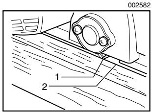
Planing operation
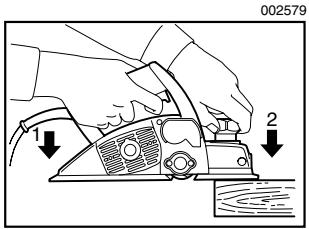
1. End
2. Start
First, rest the tool front base flat upon the workpiece surface without the blades making any contact. Switch on and wait until the blades attain full speed. Then move the tool gently forward. Apply pressure on the front of tool at the start of planing, and at the back at the end of planing. Planing will be easier if you incline the workpiece in stationary fashion, so that you can plane somewhat downhill.
The speed and depth of cut determine the kind of finish. The power planer keeps cutting at a speed that will not result in jamming by chips. For rough cutting, the depth of cut can be increased, while for a good finish you should reduce the depth of cut and advance the tool more slowly.
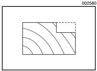
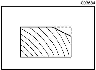
Shiplapping (Rabbeting)
To make a stepped cut as shown in the figure, use the edge fence (guide rule).
Draw a cutting line on the workpiece. Insert the edge fence into the hole in the front of the tool. Align the blade edge with the cutting line.
- Blade edge
- Cutting line
Adjust the edge fence until it comes in contact with the side of the workpiece, then secure it by tightening the screw.
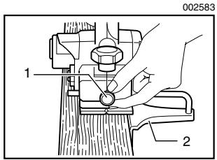
- Screw
- Edge fence
When planing, move the tool with the edge fence flush with the side of the workpiece. Otherwise uneven planing may result.
Maximum shiplapping (rabbeting) depth is 9 mm (11/32").
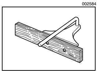
You may wish to add to the length of the fence by attaching an extra piece of wood. Convenient holes are provided in the fence for this purpose, and also for attaching an extension guide (optional accessory).
Chamfering
To make a chamfering cut as shown in the figure, align the "V" groove in the front base with the edge of the workpiece and plane it.
- V groove
MAINTENANCE
CAUTION:
Always be sure that the tool is switched off and unplugged before attempting to perform inspection or maintenance.
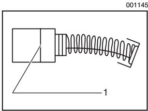
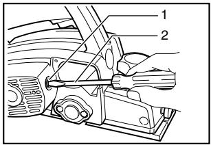
Replacing carbon brushes
- Limit mark
Remove and check the carbon brushes regularly. Replace when they wear down to the limit mark. Keep
the carbon brushes clean and free to slip in the holders. Both carbon brushes should be replaced at the same time. Use only identical carbon brushes.
Use a screwdriver to remove the chip cover.
002597
- Chip cover
- Screwdriver
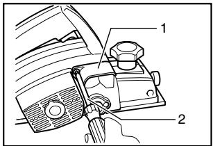
Use a screwdriver to remove the brush holder caps. Take out the worn carbon brushes, insert the new ones and secure the brush holder caps.
002598
- Brush holder cap
- Screwdriver
To maintain product SAFETY and RELIABILITY, repairs, any other maintenance or adjustment should be performed by Makita Authorized or Factory Service Centers, always using Makita replacement parts.
ACCESSORIES
CAUTION:
- These accessories or attachments are recommended for use with your Makita tool specified in this manual. The use of any other accessories or attachments might present a risk of injury to persons. Only use accessory or attachment for its stated purpose.
If you need any assistance for more details regarding these accessories, ask your local Makita Service Center.
High-speed steel Planer blade
Tungsten-carbide Planer blade (For longer blade life)
- Mini planer blade
- Sharpening holder assembly
- Blade gauge
- Set plate set
- Edge fence (Guide rule)
- Extension guide set
- Dressing stone
- Nozzle assembly
- Dust bag assembly
- Socket wrench
EN0006-1
MAKITA LIMITED ONE YEAR WARRANTY
Warranty Policy
Every Makita tool is thoroughly inspected and tested before leaving the factory. It is warranted to be free of defects from workmanship and materials for the period of ONE YEAR from the date of original purchase. Should any trouble develop during this one year period, return the COMPLETE tool, freight prepaid, to one of Makita's Factory or Authorized Service Centers. If inspection shows the trouble is caused by defective workmanship or material, Makita will repair (or at our option, replace) without charge.
This Warranty does not apply where:
- repairs have been made or attempted by others:
- repairs are required because of normal wear and tear:
the tool has been abused, misused or improperly maintained:
alterations have been made to the tool.
IN NO EVENT SHALL MAKITA BE LIABLE FOR ANY INDIRECT, INCIDENTAL OR CONSEQUENTIAL DAMAGES FROM THE SALE OR USE OF THE PRODUCT. THIS DISCLAIMER APPLIES BOTH DURING AND AFTER THE TERM OF THIS WARRANTY.
MAKITA DISCLAIMS LIABILITY FOR ANY IMPLIED WARRANTY, INCLUDING IMPLIED WARRANTY OF "MERCHANTABILITY" AND "FITNESS FOR A SPECIFIC PURPOSE," AFTER THE ONE YEAR TERM OF THIS WARRANTY.
This Warranty gives you specific legal rights, and you may also have other rights which vary from state to state. Some states do not allow the exclusion or limitation of incidental or consequential damages, so the above limitation or exclusion may not apply to you. Some states do not allow limitation on how long an implied warranty lasts, so the above limitation may not apply to you.
FRANÇAIS
SPÉCIFICATIONS
Some dust created by power sanding, sawing, grinding, drilling, and other construction activities contains chemicals known to the State of California to cause cancer, birth defects or other reproductive harm. Some examples of these chemicals are:
- lead from lead-based paints,
crystalline silica from bricks and cement and other masonry products, and - arsenic and chromium from chemically-treated lumber.
Your risk from these exposures varies, depending on how often you do this type of work. To reduce your exposure to these chemicals: work in a well ventilated area, and work with approved safety equipment, such as those dust masks that are specially designed to filter out microscopic particles.
< USA solamente >
ADVERTENCIA
3-11-8, Sumiyoshi-cho,
Anjo, Aichi 446-8502 Japan


- GENERAL SAFETY RULES
- (For All Tools)
- WARNING:
- SAVE THESE INSTRUCTIONS
- Work Area
- Electrical Safety
- Personal Safety
- Tool Use and Care
- SERVICE
- SPECIFIC SAFETY RULES
- SYMBOLS
- FUNCTIONAL DESCRIPTION
- CAUTION:
- Adjusting depth of cut
- Switch action
- ASSEMBLY
- Removing or installing planer blades
- For the correct planer blade setting
- OPERATION
- MAINTENANCE
- ACCESSORIES
- MAKITA LIMITED ONE YEAR WARRANTY
- Warranty Policy
- ADVERTENCIA
Brand : MAKITA
Model : 1902
Category : Electric planer