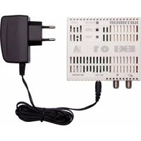
EXI 01 - Modem KATHREIN - Free user manual and instructions
Find the device manual for free EXI 01 KATHREIN in PDF.


| Product Type | Satellite Receiver |
| Brand | Kathrein |
| Model | EXI 01 |
| Dimensions (W x D x H) | 260 x 180 x 45 mm |
| Weight | 0.9 kg |
| Power Supply | 12V DC, 0.5A |
| Power Consumption | 6 W (max) |
| Frequency Range | 950 – 2150 MHz |
| Input Connector | F-type female |
| Output Connector | SCART, HDMI |
| Supported Satellite Standards | DVB-S, DVB-S2 |
| Main Functions | Digital satellite reception, channel list management, electronic program guide (EPG), parental lock |
| Care and Cleaning | Wipe with a soft, dry cloth; do not use liquid cleaners |
| Safety Precautions | Keep away from moisture, do not open the device, use only the supplied power adapter |
| Spare Parts and Repairability | Remote control, power adapter available as spare parts; device is not user-serviceable |
| Operating Temperature | 0°C to 40°C |
| Storage Temperature | -20°C to 60°C |
| General Information | Designed for indoor use only; complies with CE standards |
Frequently Asked Questions - EXI 01 KATHREIN
User questions about EXI 01 KATHREIN
0 question about this device. Answer the ones you know or ask your own.
Ask a new question about this device
Download the instructions for your Modem in PDF format for free! Find your manual EXI 01 - KATHREIN and take your electronic device back in hand. On this page are published all the documents necessary for the use of your device. EXI 01 by KATHREIN.
USER MANUAL EXI 01 KATHREIN
* Quality of Service
■ Modem for the Kathrein IP over coax system "K-LAN" (based on the IEEE 1901 standard)
■ Creation of a home network over the existing terrestrial coax distribution for the satellite system. This reduces the cost of installation - no new network cables need be laid
■ Ideal for the network connection of receivers, TV sets and Blu-ray players. In addition, a PC and other network-capable devices can easily be connected via a router (such as Fritzbox)
- > 500-Mbit data throughput (gross) is sufficient for several HD streams plus data transmission between PCs. QoS *) allows prioritisation of the respective services
■ Integral highly selective diplexer - no interference between FM, TV and satellite signals.
No additional splitters are necessary
■ High screening factor prevents interference
■ 1 input (IP & Sat/TV/FM); 1 output (1 x Sat/TV/FM); 1 x Ethernet RJ45. DC is looped through
■ 128-bit AES encryption. Secure private network connection at the push or a button - no software required
In conjunction with the optimised EXI 3508 distribution system, distances of >700 m are achievable in the IP frequency range
- The modem can be remotely fed by the connected satellite receiver, using the port on the EXI 30 outlet. In all other cases the power is supplied by the plug-in power supply unit. The EXI 30 outlet has been specially developed for the K-LAN ^**
■ Eco Power Mode: The modem automatically switches to stand-by until it is "woken up" again by the network. Consumption: 0.5 Watt in stand-by/max. 4.2 Watt in operation
*1 Quality of Service
**1 Alternatively the ESD 84 and ESD 32 outlets can also be used

Scope of supply
EXI 01
■ Energy-efficient plug-in power supply unit for power supply, e.g. for operation at a PC
■ Screened network cable 1.5 m Cat 6A
Accessories
■ High-pass fi Iter EXI 90 BN (20510062): If the EXI 01 is operated via a multi-switch not from the EXI range the high-pass fi iter must be screwed on to the terrestrial input of the multi-switch. This isolates the downstream multi-switch and prevents reception and emission in the IP frequency range by and from the terrestrial antenna
■ Software EXI 700: Displays the visible modems on a network (download from: www.kathrein.de)
■ EXI 30 (article no.: 21110024): Outlet remotely fed from the SAT port, with optimum selection for data and RF signals
General instructions
If a switchable LNB such as UAS 585 is used, or a multi-switch with a power consumption of more than 50 mA per connection, the modem must be powered using the power supply unit included
■ If the modem is driven from a PC or the like, an EMK 03 terminating resistor should be screwed to the unused output
Installation and safety instructions

- Failure to comply with these instructions will result in voiding of warranty cover.
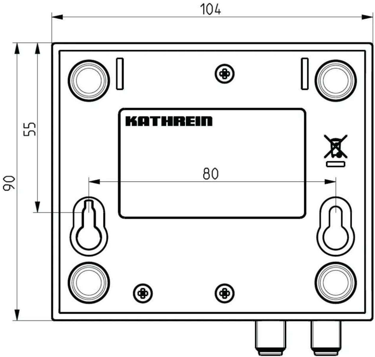
- The equipment may only be installed in dry areas indoors. Do not install on or against highly combustible materials. For wall mounting, refer to the point "EXI 01 dimensions for wall mounting" in these user instructions.
■ Make sure that the ventilation slots on the device are not covered, to ensure adequate thermal dissipation (min distance 5 cm) - Do not install the unit close to a heater or expose it to direct sunlight. Do not operate it in damp locations. Only use the unit in a moderate climate, not in tropical conditions! Do not place naked flames such as candles on top of the unit! There is a risk of fi re!
- Fixings: screws, max ∅: 4 mm (not included)
■ Connectors for the coaxial cable: RF plugs 75 Ω (series F) to EN 61169-24.

■ If the cable inner conductor diameter is greater than 1.2 mm, or in case of burr, the device sockets may be damaged beyond repair.


Set-up
The Kathrein EXI 01 modem and the integral modem within the EXI 3508 multi-switch are protected with a factory-set network security key. For simple commissioning of the two modems, connect a coaxial cable to the socket ▲. If the modem is not remotely fed by the receiver, the plug-in power supply unit must be plugged in to the "DC" socket. The network devices to be connected, such as the router and receiver, are connected using the Ethernet cable included. This is plugged in to the RJ 45 socket provided. The "Power" and "Coax/Link" LEDs light up. The data connection is established. Up to 64 modems can be linked together in this way.
Other devices such as TV sets, receivers or radios can be connected to the socket ▼The RF signal is looped through. No external splitters are necessary. High-selectivity filters ensure that the data signal does not generate interference at these devices. See also "Info on the Coaxial Distribution System".
Additional security:
In a coaxial distribution system, all the connected Kathrein modems can "see" each other. If you wish to build a private network with the modems that belong to you, proceed as follows:
- Press the "Pairing" button and keep it depressed for approx. 12 seconds. Both LEDs go out briefly. The network key is deleted. The "Power" LED lights up, but the "Coax/Link" LED remains off. Perform this step for all the devices that you wish to add to your private network!
- Now briefy press the "Pairing" button on one of your modems (for approx. 1 second). The "Power" LED starts to flash. Now at the next modem briefy press the "Pairing" button. The two modems exchange a secret network key and connect to each other. You must press the second button within approx. three minutes after the first. Once the procedure is complete, both LEDs light up continuously again. Each further modem can be added to the private network in the same way. The pairing can be started at any modem on your private network.
Resetting:
Pressing the "Reset" button resets the modem to its factory settings. Since this also restores the original factory setting for the network key, the modem is now once again generally visible and no longer belongs to your private network.
Stand-by:
After a few minutes with no data traffic, the EXI 01 switches itself automatically into stand-by mode. The "Power" LED fl ashes slowly (red - green).
Info on the coaxial distribution system
Ideally the EXI 01 modem is operated in combination with the EXI 3508 multi-switch with integral modem. The terrestrial distribution system of this multi-switch is specially matched to this application and thus offers especially long range capabilities for the installation (>700 m for the data range). An integral high-pass filter for the terrestrial input prevents undesirable propagation of your network data from a connected antenna.
Operation with a conventional multi-switch also poses no problems. In this case the EXI 90 external high-pass filter must be screwed on to the terrestrial input, in order adapt the terrestrial distribution system.
To achieve optimum performance, make sure that all components of the overall distribution system (including the outlets used) support the frequency range of 5 to 68 MHz.
Overview of the LEDs
| LED ... Status EXI 01 | ||
| “Power” LED Lights | up green in operation | |
| Lights up red Stand-by | ||
| Is off No power supply | ||
| “Coax/Link” LED Lights | up green Connection established in the coax network (optimum connection) | |
| Lights up orange Connection still OK | ||
| Lights up red Bad connection - data throughput restricted | ||
| Is off Damping too high (>90 dB), cable breakage or no matching network key | ||
| Ethernet socket | ||
| Left hand LED Flashes | orange Ethernet activity | |
| Right hand LED | Lights up green | GBit connection |
| Is off at ≤100 MBit connection |
Overview of buttons
| Button is ... | Triggers the following action ... | |
| Pairing | Pressed briefly (1-3 seconds) | A further modem is connected |
| Pressed longer (approx. 12 seconds) | Modem is prepared for connection into a private network. Network key is deleted | |
| Reset | Pressed briefly (1-3 seconds) | Reset to factory setting. The factory setting for the network key is restored |
Installation examples
Connection to a receiver and remote feed to the modem by the receiver
Connection to a laptop/PC and power supply to the modem by power supply unit
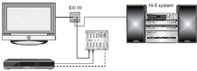
flowchart
graph TD
    A["Computer"] --> B["EXI 30"]
    B --> C["Server"]
    C --> D["Hi-fi system"]
    D --> E["Host 1"]
    D --> F["Host 2"]
    D --> G["Host 3"]

Connection to a twin receiver and remote feed to the modem by the receiver

System examples (symbolic representation)

flowchart
graph TD
    A["SatAn®"] --> B["Sat Signal"]
    B --> C["Network"]
    C --> D["2x Sat Signal * network"]
    D --> E["Twin-Receiver"]
    E --> F["Sat-Signal * network"]
    F --> G["DHCP Server, router (e.g. Fritzbox)"]
    G --> H["Optional NAS"]
    H --> I["NT"]
    style A fill:#f9f,stroke:#333
    style B fill:#ccf,stroke:#333
    style C fill:#cfc,stroke:#333
    style D fill:#fcc,stroke:#333
    style E fill:#cff,stroke:#333
    style F fill:#ffc,stroke:#333
    style G fill:#cfc,stroke:#333
    style H fill:#fcc,stroke:#333
    style I fill:#fff,stroke:#333

flowchart
graph TD
    A["SatAn® Satellite"] --> B["ExR 2558"]
    C["ExR 2508"] --> D["ExR 2558"]
    B --> E["ExR 2508"]
    D --> E
    E --> F["ExR 2508"]
    style A fill:#f9f,stroke:#333
    style C fill:#f9f,stroke:#333
    style B fill:#ccf,stroke:#333
    style D fill:#ccf,stroke:#333
    style E fill:#ccf,stroke:#333
    style F fill:#ccf,stroke:#333
*) Separation of the IP frequency range by and from the terrestrial antenna and other downstream multi-switches is performed by the screwed-on EXI 90 high-pass fi lter
**) Separation of the IP frequency range by and from the terrestrial antenna and other downstream multi-switches is performed here by the integral high-pass fi Iter within the EXI 3508

flowchart
graph TD
    A["SatAn"] --> B["Satellite"]
    B --> C["ExR 2558"]
    C --> D["ExR 3508"]
    D --> E["Satellite"]
    C --> F["ExR 2558"]
    D --> G["ExR 3508"]
    F --> H["Satellite"]
    G --> I["Satellite"]
    style A fill:#f9f,stroke:#333
    style B fill:#ccf,stroke:#333
    style C fill:#cfc,stroke:#333
    style D fill:#cfc,stroke:#333
    style E fill:#fcc,stroke:#333
    style F fill:#cff,stroke:#333
    style G fill:#cff,stroke:#333
    style H fill:#ffc,stroke:#333
    style I fill:#ffc,stroke:#333
Possible causes of faults, and their remedies
Problem Possible cause Solution
| “Coax/Link” LED does not light up | No coax connection | Ensure the coaxial cables are connected without any short circuits |
| “Coax/Link” LED does not light up | Damping between the modems is too high | Check whether the selected port on the RF outlet/multi-switch supports the frequency range 5-68 MHz |
| “Coax/Link” LED does not light up | No pairing | The modem has not yet been assigned a valid network key. Perform the relevant points during commissioning |
Technical Specifications
| Type EXI 01 | |||
| Part no. 20510061 | |||
| Input output 1 x | DC + IP & FM + TV + Sat | 1 xDC + FM + TV + Sat | |
| Frequency range MHz 2-2150 87.5-2150 | |||
| Frequency range IP (IEEE 1901) MHz 2-68 | 1) | ||
| Through loss dB - | 1 | ||
| Screening factor | dB | 5-300 MHz > 85300-470 MHz > 80470-1000 MHz > 751000-2150 MHz > 55 | |
| Permissible remote power feed at the output | V | 12-20 | |
| Current consumption of the modem, max. | mA | 350 | |
| Power consumption at max. data rate | W | Approx. 4.2 | |
| Power consumption in stand-by | W | Approx. 0.5 | |
| Permissible current consumption of the multi-switch from the receiver when remotely fed 2) | mA | 50 | |
| Gross data rate | Mbit/s | 500 | |
| Permissible ambient temperature | °C | 0 to + 40 | |
| Connections | F-connectors, RJ45, 5.5 x 2 mm latching plug | ||
| Standards supported | IEEE1901 | ||
| Dimensions (W x L x H) | mm | 104 x 101 x 29.5 | |
| Packing unit/weight | Units/kg | 1 (10)/approx. 0.35 | |
| Power supply unit | ||
| Nominal input voltage V | 230 | |
| Voltage secondary | V | 12 |
| Max. output current | mA | 600 |
| Nominal input power (300/0mA load) | W | 4.5/0.25 |
| Satisfies the directives | 2009/125/EC in accordance with regulations 278/2009/EC, 2006/95/EC together with the standards current at the time of delivery | |
1) Of which actually used: 8-68 MHz
2) If the plug-in power supply unit is being used, the full feeder current of the receiver is available for the connected consumers
Dimensions of EXI 01


Electronic equipment
Electronic equipment is not domestic waste – in accordance with directive 2012/19/EU OF THE EUROPEAN PARLIAMENT AND THE COUNCIL dated 4th July 2012 concerning used electrical and electronic appliances, it must be disposed of properly. At the end of its service life, take this unit for disposal at a designated public collection point.
Dimensions of EXI 01 for wall mounting (drilling template)
Brand : KATHREIN
Model : EXI 01
Category : Modem