
FORCE PRO WIRELESS - Game controller MSI - Free user manual and instructions
Find the device manual for free FORCE PRO WIRELESS MSI in PDF.


| Product Type | Racing wheel with force feedback |
| Brand | MSI |
| Model | FORCE PRO WIRELESS |
| Connectivity | Wireless 2.4 GHz, USB-C (recharging) |
| Force Feedback | Dual gear motor, adjustable force |
| Compatibility | Windows 10/11, PlayStation 4, PlayStation 5 |
| Power | Rechargeable lithium-ion battery, 10 hours battery life |
| Dimensions (wheel) | 28 x 28 x 28 cm |
| Weight | 2.5 kg |
| Color | Black with red accents |
| Main features | Force feedback, gear shift paddles, 3-axis pedals, programmable wheel controls |
| Care and cleaning | Wipe with a soft dry cloth; do not use abrasive products |
| Safety | Use the suction mount on a stable surface; avoid shocks |
| Spare parts and repairability | Wheel, pedals, power adapter, USB cable; repair by MSI authorized center |
| Warranty | 2 years |
Frequently Asked Questions - FORCE PRO WIRELESS MSI
User questions about FORCE PRO WIRELESS MSI
0 question about this device. Answer the ones you know or ask your own.
Ask a new question about this device
Download the instructions for your Game controller in PDF format for free! Find your manual FORCE PRO WIRELESS - MSI and take your electronic device back in hand. On this page are published all the documents necessary for the use of your device. FORCE PRO WIRELESS by MSI.
USER MANUAL FORCE PRO WIRELESS MSI
| 1 | Left / Right Thumbsticks | 13 | Lighting Switch |
| 2 | Directional Pad (D-Pad) | 14 | Pairing Button |
| 3 | Top Cover | 15 | USB-C Port |
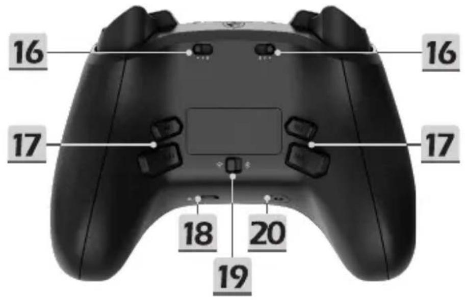
| 4 | Power / Battery Indicator LED | 16 | 3-level Trigger Locks |
| 5 | Share Button | 17 | Customizable Rear Buttons(M1/M2/M3/M4) |
| 6 | ABXY Buttons | ||
| 7 | Menu Button | 18 | Mute Button |
| 8 | Status LED | 19 | Wireless Mode Switch |
| 9 | Xbox Button | 20 | 3.5mm Headset Jack |
| 10 | View Button | 21 | 3m USB-C to A Cable |
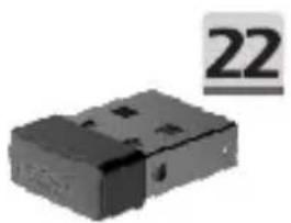
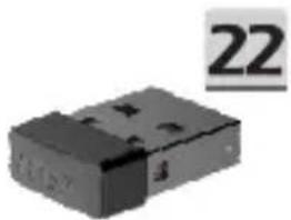
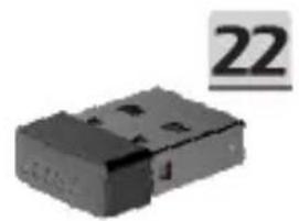
| 11 | Bumpers (LB & RB) | 22 | Wireless USB Dongle |
| 12 | Triggers (LT & RT) |
Connect to PC
Power on the Controller by pressing the Xbox Button.
- Wired Connection: Connect to PC with the USB-C cable until the Status LED turns solid WHITE.
- 2.4 GHz Wireless Connection: First, toggle the Wireless Mode Switch to . Next, plug the Wireless USB Dongle into an available USB port, until the Status LED turns from flashing GREEN to solid GREEN.
- Bluetooth Pairing: Toggle the Wireless Mode Switch to , and press and hold the Pairing Button. Then, locate the Bluetooth icon on your PC taskbar, and click 'Add a device' to select MSI FORCE PRO WIRELESS from the list of devices until the Status LED turns from flashing BLUE to solid BLUE.
- If Pairing Fails: The Status LED flashes RED 3 times. Re-pair the controller using one of the above connectivity methods.
Connect to Xbox Console (Wired Connection Only)
Power on the controller, then connect it to the console using the USB-C cable and wait until the Status LED turns solid WHITE.
Connect to Headset
Connect a 3.5mm wired headset and unmute the microphone (muted by default) by pressing the Mute Button.
The orange cycling effect will then appear on both thumbsticks.
Lighting Control
- Adjust Lighting Mode: Press the Lighting Switch once.
Recharge the Controller (via USB-C Cable)
- Indicator LED off: Power off.
- Indicator LED flashing RED: Battery is low within 1%-29%.
- Indicator LED flashing YELLOW: Battery is charging within 30%-69%.
- Indicator LED flashing GREEN: Battery is charging within 70%-99%.
- Indicator LED solid GREEN: Battery is fully charged.
Feature Compatibility
| Platform1 | PC Xbox | 2 | Android | ||
| Feature USB-C | Bluetooth 2.4 | GHz USB-C | Bluetooth3 | ||
| Impulse Trigger V V | |||||
| Vibration Feedback V V V V V | |||||
| Audio V V | |||||
| MSI Mystic Light V V V V V | |||||
| MSI Center V | |||||
1 PC & Xbox profile settings must be set up in the MSI Center then saved in the onboard memory. 2 Xbox includes Xbox X|S, and all Xbox One consoles in wired mode. 3 Bluetooth is available on Windows 10/11 and Android 8 and Later. 4 The controller requires a driver to connect via Bluetooth on a PC. Please download and extract the driver installation file from https://www.msi.com/Gaming-Gear/FORCE-PRO-WIRELESS/support
Customization & Firmware Updates
Download the latest version of MSI Center to customize controller settings such as reconfiguring buttons, vibration, thumbsticks, triggers, lighting and power saving or to receive firmware updates.
MSI Center can be downloaded from: https://www.msi.com/Landing/MSI-Center
Power off / Power Saving / Reset
- To power off the controller, press the Xbox Button for more than 3 seconds until the Status LED turns off.
- If there is no activity for 2 minutes, the Status LED will flash 3 times as a reminder and enter idle mode.
- If there is no activity for 10 minutes, or if any of the thumbsticks are removed, the controller will power off
- Press and hold the Xbox Button for 12 seconds to perform a hardware reset and reboot the controller.
Swap Removable Parts
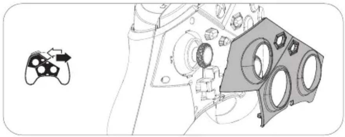
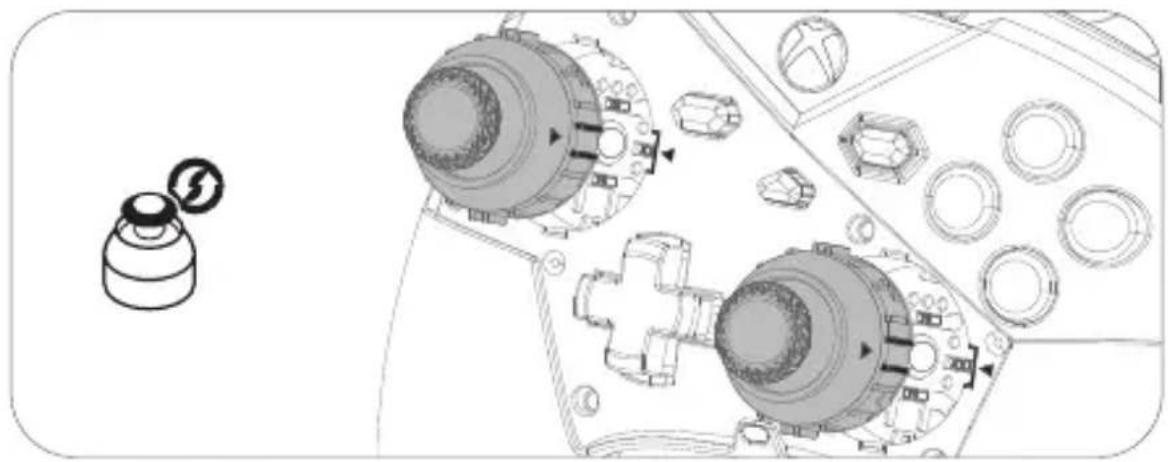
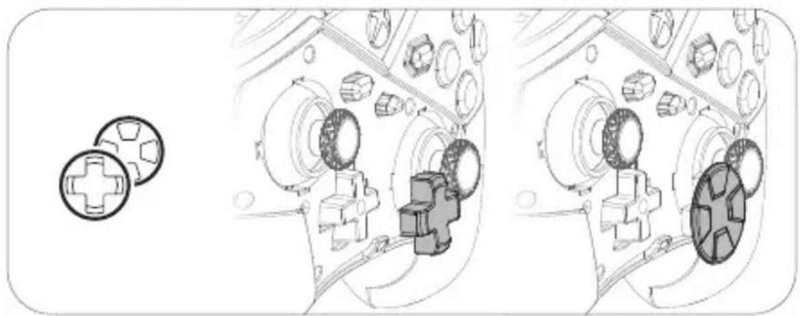
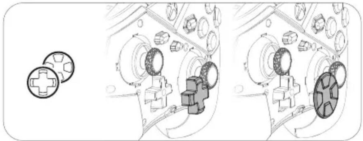
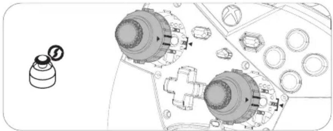
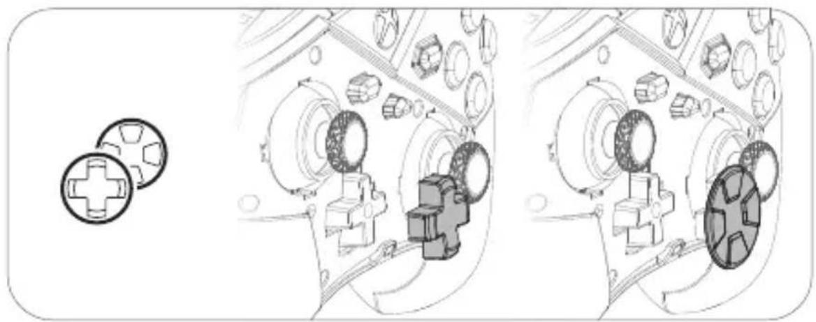
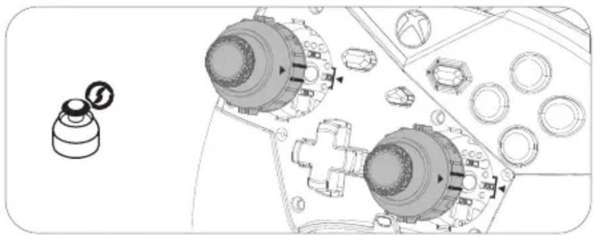
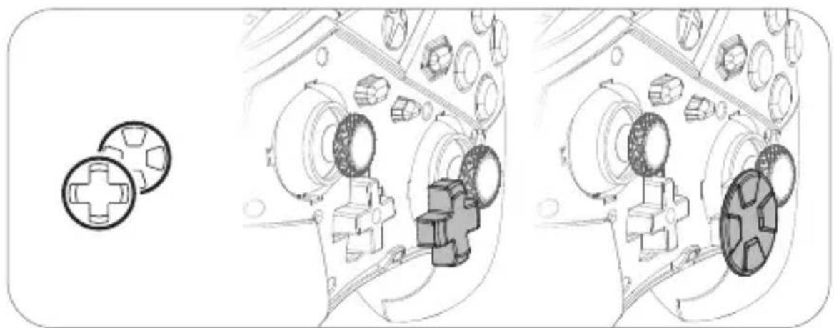
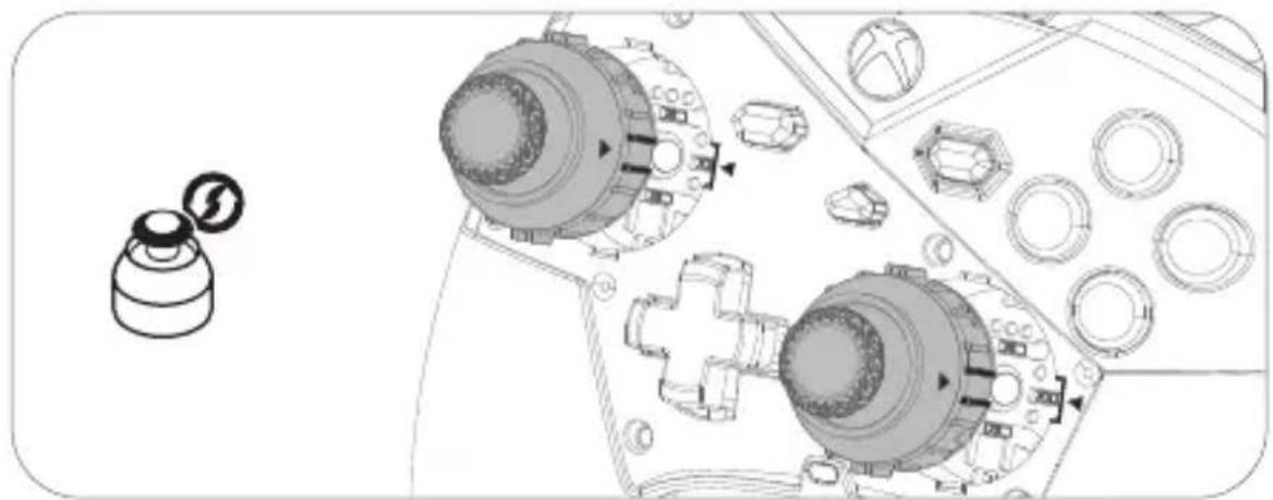
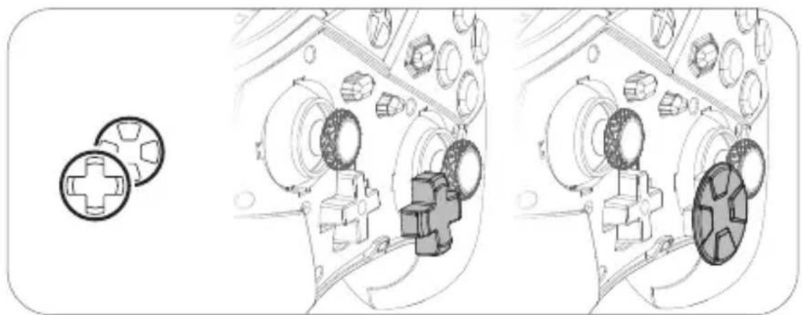
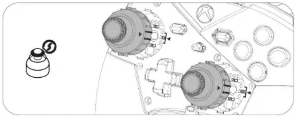
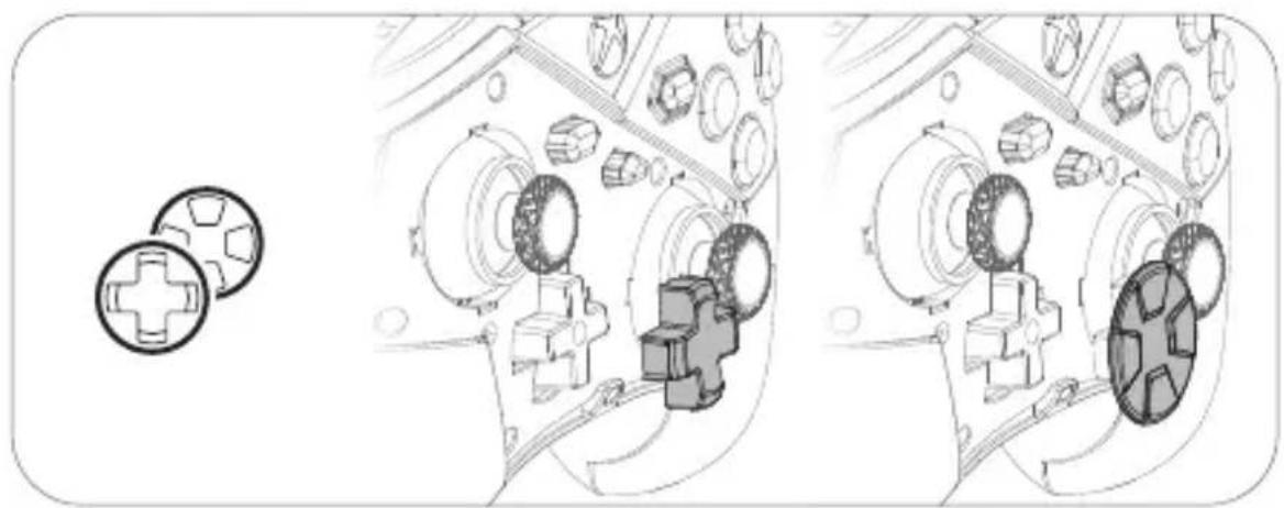
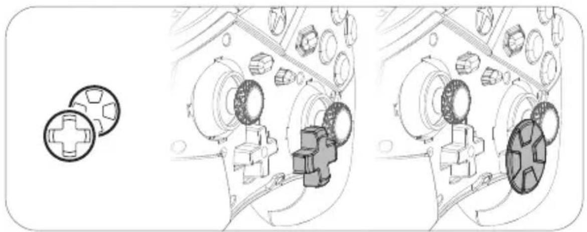
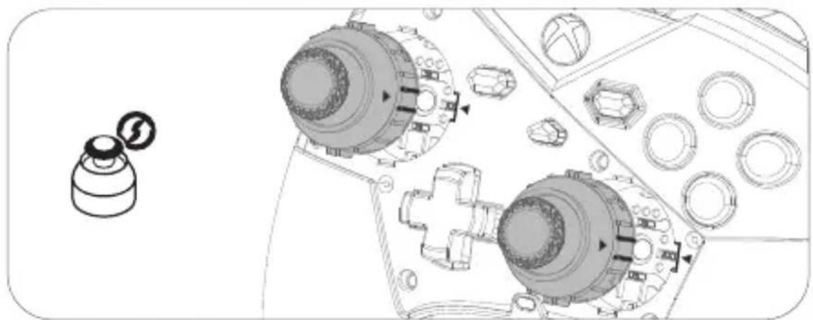
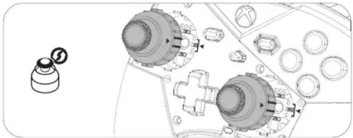
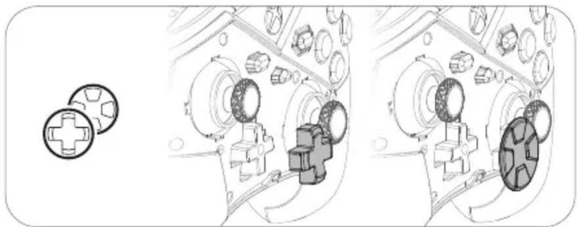
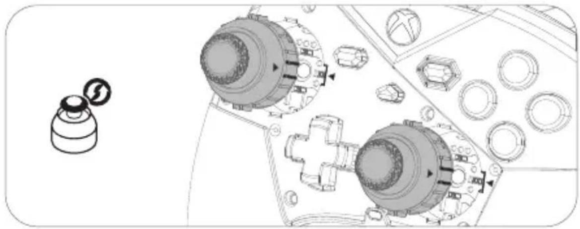
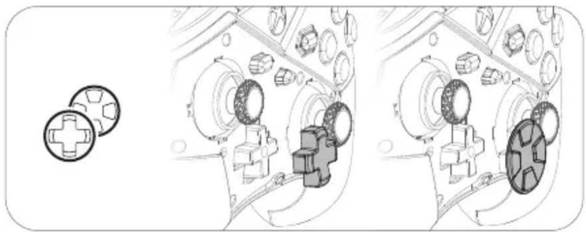
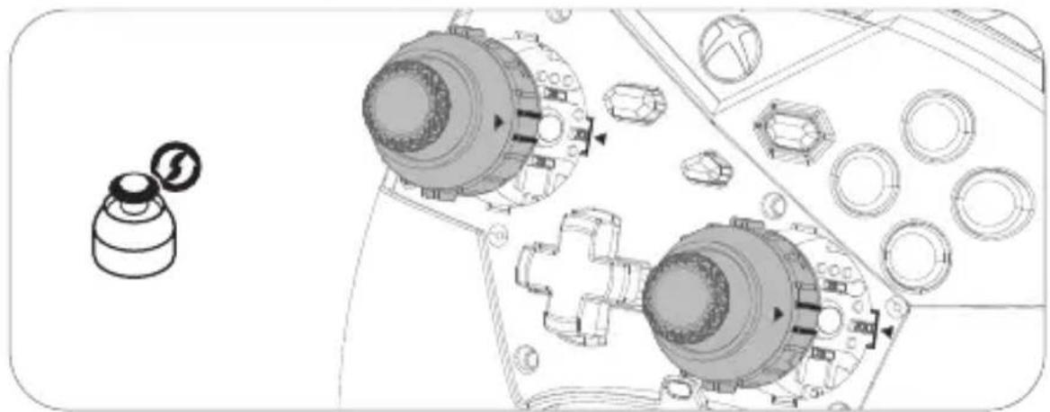
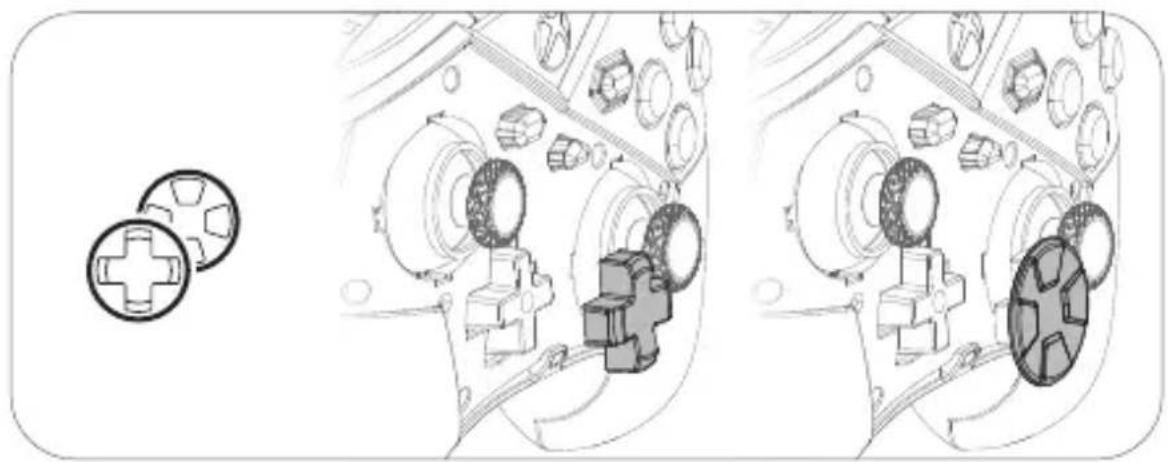
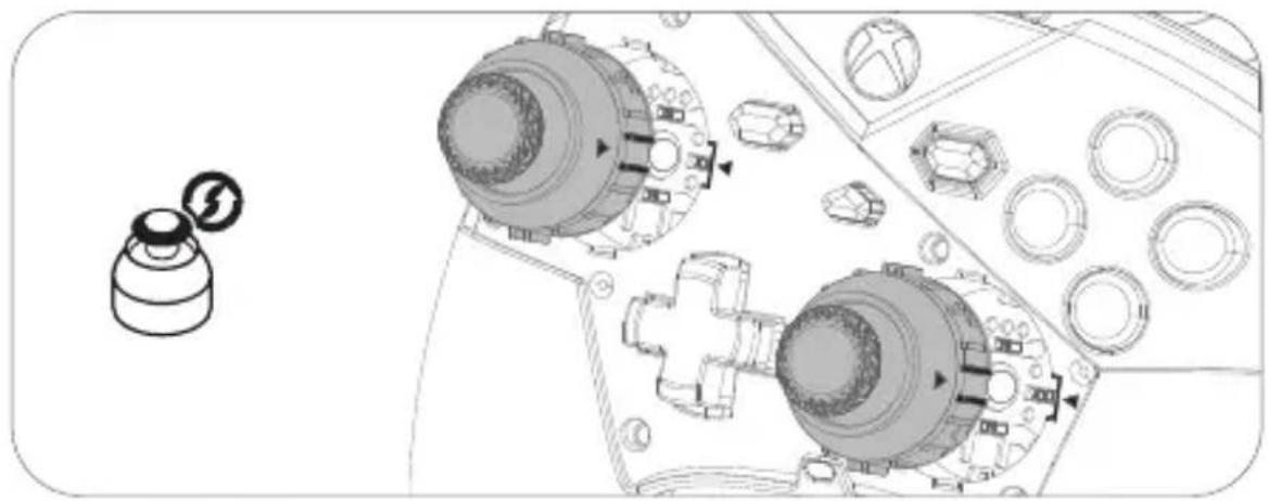
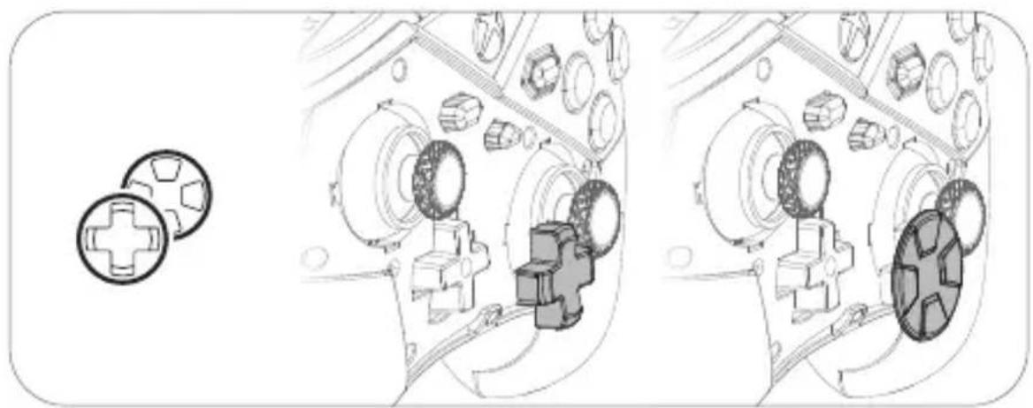
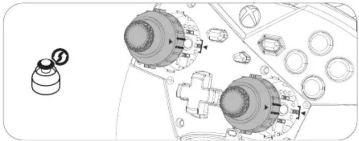
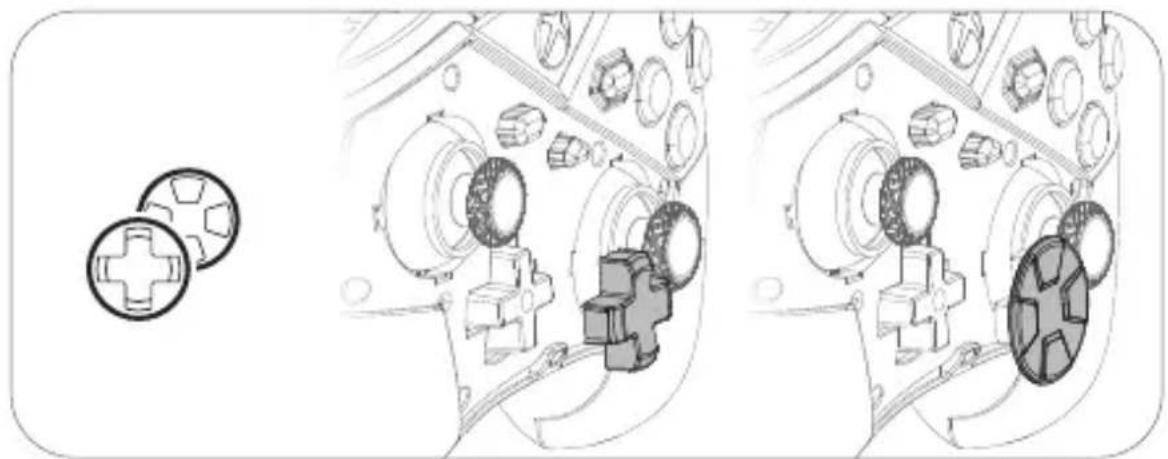
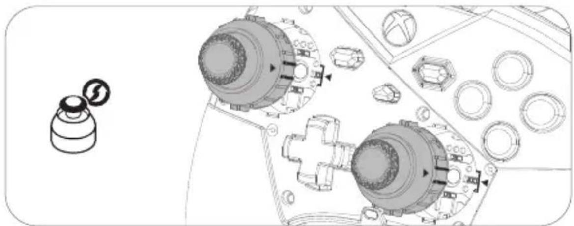
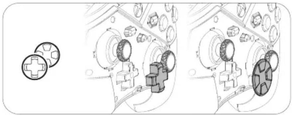
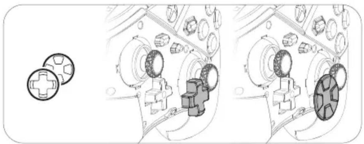
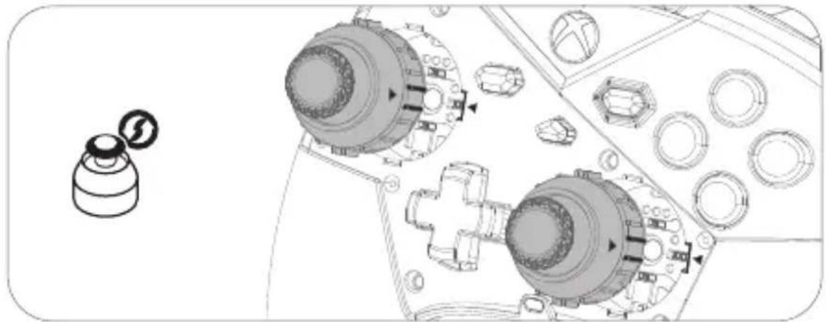
* Please note that the top cover must be removed before replacing the D-pad or thumbsticks. * Please be cautious of the removable D-pad, top cover and thumbsticks to avoid potential loss or damage.
* For more information, please visit MSI official website.


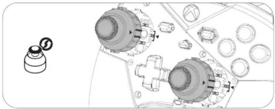
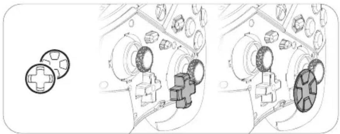
https://www.msi.com/Landing/MSI-Center
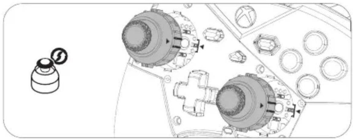

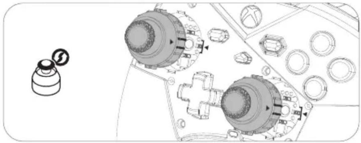


| 1 | Tombol Kiri / Kanan | 13 | Sakelar Lampu |
| 2 | Directional Pad (D-Pad) | 14 | Tombol Perpasangan |
| 3 | Penutup Atas | 15 | Port USB-C |
| 4 | LED Indikator Daya / Baterai | 16 | Kunci Trigger 3-level |
| 5 | Tombol Bagikan | 17 | Tombol Belakang yang Bisa Dikustomisasi (M1/M2/M3/M4) |
| 6 | Tombol ABXY | ||
| 7 | Tombol Menu | 18 | Tombol Senyap |
| 8 | LED Status | 19 | Tombol Mode Nirkabel |
| 9 | Tombol Xbox | 20 | Steker Headset 3,5mm |
| 10 | Tombol Tampilan | 21 | Kabel USB-C ke A 3m |
| 11 | Bumper (LB & RB) | 22 | Dongle USB Nirkabel |
| 12 | Trigger (LT & RT) |



















https://www.msi.com/Landing/MSI-Center


FCC Compliance Statement
This device complies with Part 15 of the FCC Rules. Operation is subject to the following two conditions:
• This device may not cause harmful interference. • This device must accept any interference received, including interference that may cause undesired operation.
This equipment has been tested and found to comply with the limits for a Class B digital device, pursuant to Part 15 of the FCC Rules. These limits are designed to provide reasonable protection against harmful interference in a residential installation.
This equipment generates, uses, and can radiate radio frequency energy and, if not installed and used in accordance with the instructions, may cause harmful interference to radio communications. However, there is no guarantee that interference will not occur in a particular installation. If this equipment does cause harmful interference to radio or television reception, which can be determined by turning the equipment off and on, the user is encouraged to try to correct the interference by one or more of the following measures:
- Reorient or relocate the receiving antenna.
- Increase the separation between the equipment and receiver.
- Connect the equipment into an outlet on a circuit different from that to which the receiver is connected.
- Consult the dealer or an experienced radio/TV technician for help.
CAUTION:
Any changes or modifications not expressly approved by the grantee of this device could void the user's authority to operate the equipment. Where shielded interface cables have been provided with the product or specified additional components or accessories elsewhere defined to be used with the installation of the product, they must be used in order to ensure compliance with FCC regulations.
Services web address: www.msi.com
RF Exposure Statements
The device has been evaluated to meet general RF exposure requirements. The device can be used in portable exposure conditions without restriction.

CE RED Compliance Statement
EU Simplified Declaration of Conformity
Hereby, msi Inc. declares that the radio equipment type MS-8ZBZ is in compliance with Directive 2014/53/EU. The full text of the EU Declaration of conformity is available at the following internet address: https://www.msi.com

UKCA Compliance Statement UKCA Simplified Declaration of Conformity
Hereby, msi Inc. declares that the radio equipment type MS-8ZBZ is in compliance with the essential requirements and other relevant provisions of the Radio Equipment Regulations 2017. The full text of the UK Declaration of Conformity may be found at the following internet address: https://www.msi.com

ISED Compliance Statement
This device contains licence-exempt transmitter(s)/receiver(s) that comply with Innovation, Science and Economic Development Canada's licence-exempt RSS(s). Operation is subject to the following two conditions: (1) This device may not cause interference. (2) This device must accept any interference, including interference that may cause undesired operation of the device.
The device has been evaluated to meet general RF exposure requirement. The device can be used in portable exposure condition without restriction.
This Class B digital apparatus complies with Canadian ICES-003.
1 Replacement of battery with an incorrect type that can defeat a safeguard (for example, in the case of some lithium battery types); 2 Disposal of a battery into fire or a hot oven, or mechanically crushing or cutting of a battery, that can result in an explosion; 3 Leaving a battery in an extremely high temperature surrounding environment that can result in an explosion or the leakage of flammable liquid or gas; 4 A battery subjected to extremely low air pressure that may result in an explosion or the leakage of flammable liquid or gas. 5 High or low extreme temperatures that a BATTERY can be subjected to during use, storage or transportation; and 6 Low air pressure at high altitude.
Warning
1 Replacement of battery with an incorrect type that can defeat a safeguard (for example, in the case of some lithium battery types); 2 Disposal of a battery into fire or a hot oven, or mechanically crushing or cutting of a battery, that can result in an explosion; 3 Leaving a battery in an extremely high temperature surrounding environment that can result in an explosion or the leakage of flammable liquid or gas; 4 A battery subjected to extremely low air pressure that may result in an explosion or the leakage of flammable liquid or gas.
Japan VCCI Class B Declaration
Company: MSI Korea Co., Ltd.
Product Name: Controller
Model Name: MS-8ZBZ
Date of Manufacture: 2024
Manufacturer and Country of Origin: MSI/China
R-R-MSI-MS-8ZBZ
Company: MSI Korea Co., Ltd.
Product Name: Receiver
Model Name: GM01WD
Date of Manufacture: 2024
Manufacturer and Country of Origin: MSI/China
R-R-MSI-GM01WD
Specifications
Model: MS-8ZBZ (Controller) / GM01WD (Wireless USB Dongle)
Controller Input: DC 5.0V / 1000mA
Wireless USB Dongle Input / Input: DC 5.0V / 30mA
Frequency Range: 2.400 - 2.4835GHz
Controller Output < 0 dBm
Wireless USB Dongle Output < 0 dBm
| Temperature USB Wireless Dongle | |
| Operating 0 ~ 40°C 10 ~ 95% | |
| Storage -30 ~ 70°C 10 ~ 95% |
REACH
Complying with the REACH (Registration, Evaluation, Authorisation, and Restriction of Chemicals) regulatory framework, we published the chemical substances in our products at MSI REACH website at https://csr.msi.com/global/Product-Chemical-Management.
Safety Instructions
Read the safety instructions carefully and thoroughly.
- All cautions and warnings on the equipment or user's manual should be noted.
- Do not leave the device in an unconditioned environment with a storage temperature above 60°C (140°F) or below 0°C (32°F), which may damage the device.
- This device should be operated under maximum ambient temperature of 40°C (104°F).
Declaration of the Presence Condition of the Restricted Substances Marking
Declaration of the Presence Condition of the Restricted Substances Marking
| 設備名稱:無線搖摆·型號(型式):MS-SZBZEquipment name Type designation (Type) | ||||||
| 單元 Unit | 限用物質及其化學符號Restricted substances and its chemical symbols | |||||
| 鉛Lead(Pb) | 汞Mercury(Hg) | 鎘Cadmium(Cd) | 六價鉻Hexavalent chromium( Cr-3 ) | 多溴聯苯Polybrominated biphenyls(PBB) | 多溴二苯醚Polybrominated diphenyl ethers(PEDE) | |
| 印刷電路及電子組件 | ○ | ○ | ○ | ○ | ○ | ○ |
| 外殼 | ○ | ○ | ○ | ○ | ○ | ○ |
| 接收器及配件 | ○ | ○ | ○ | ○ | ○ | ○ |
| 線材 | ○ | ○ | ○ | ○ | ○ | ○ |
| 備考1. “超出0.1 wt %”及“超出0.01 wt %”係指限用物質之百分比含量超出百分比含量基準值。Note 1: “Exceeding 0.1 wt %” and “exceeding 0.01 wt %” indicate that the percentage content of the restricted substance exceeds the reference percentage value of presence condition.備考2. “○”係指該項限用物質之百分比含量未超出百分比含量基準值。Note 2: “○” indicates that the percentage content of the restricted substance does not exceed the percentage of reference value of presence.備考3. “—”係指該項限用物質為排除項目。Note 3: The “—” indicates that the restricted substance corresponds to the exemption. | ||||||
Names and content of toxic and hazardous substances or elements in the product

- CONNECT TO PC
- CONNECT TO XBOX CONSOLE (WIRED CONNECTION ONLY)
- CONNECT TO HEADSET
- LIGHTING CONTROL
- RECHARGE THE CONTROLLER (VIA USB-C CABLE)
- CUSTOMIZATION & FIRMWARE UPDATES
- POWER OFF / POWER SAVING / RESET
- SWAP REMOVABLE PARTS
- FCC COMPLIANCE STATEMENT
- CAUTION
- RF EXPOSURE STATEMENTS
- CE RED COMPLIANCE STATEMENT
- EU SIMPLIFIED DECLARATION OF CONFORMITY
- UKCA COMPLIANCE STATEMENT UKCA SIMPLIFIED DECLARATION OF CONFORMITY
- ISED COMPLIANCE STATEMENT
- WARNING
- JAPAN VCCI CLASS B DECLARATION
- SPECIFICATIONS
- REACH
- SAFETY INSTRUCTIONS
- DECLARATION OF THE PRESENCE CONDITION OF THE RESTRICTED SUBSTANCES MARKING
Brand : MSI
Model : FORCE PRO WIRELESS
Category : Game controller