GA-7VAX-A - Motherboard GIGABYTE - Free user manual and instructions
Find the device manual for free GA-7VAX-A GIGABYTE in PDF.
Download the instructions for your Motherboard in PDF format for free! Find your manual GA-7VAX-A - GIGABYTE and take your electronic device back in hand. On this page are published all the documents necessary for the use of your device. GA-7VAX-A by GIGABYTE.
USER MANUAL GA-7VAX-A GIGABYTE
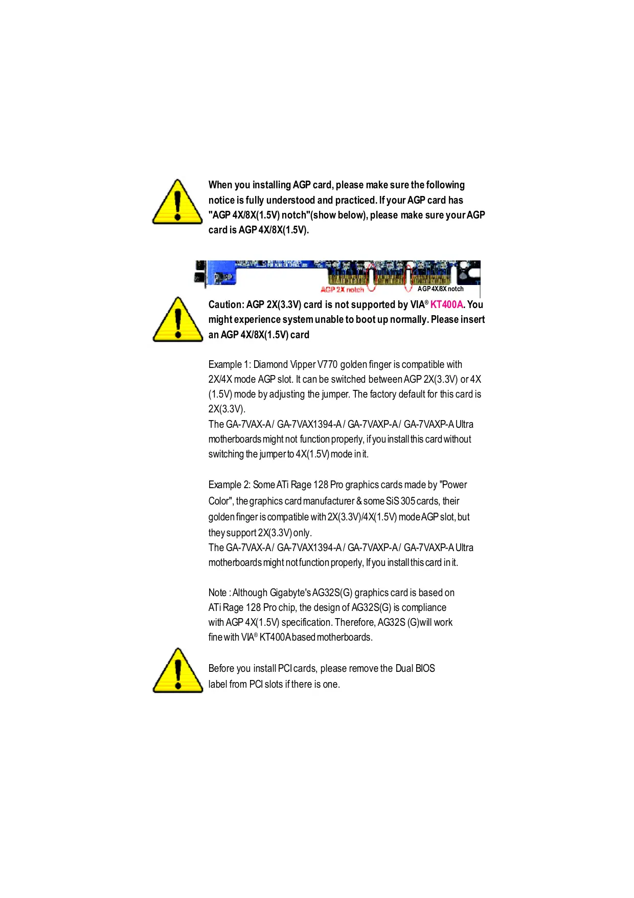
When you installing AGP card, please make sure the following notice is fully understood and practiced. If your AGP card has "AGP 4X/8X(1.5V) notch"(show below), please make sure your AGP cardis AGP 4X/8X(1.5V). ACP 2x noteh / AGP4X/ÆEX notch Caution: AGP 2X(3.3V) card is not supported by VIA® KT400A. You might experience system unable to boot up normally. Please insert an AGP 4X/8X(1.5V) card Example 1: Diamond Vipper V770 golden finger is compatible with 2X/4X mode AGP slot. It can be switched between AGP 2X(3.3V) or 4X (1.5V) mode by adjusting the jumper. The factory default for this card is 2X(3.3V). The GA-7VAX-A/ GA-7VAX1394-A/ GA-7VAXP-A/ GA-7VAXP-A Ultra motherboards might not function properly, ifyou install this card without switching the jumperto 4X(1.5V) mode init. Example 2: Some ATi Rage 128 Pro graphics cards made by "Power Color”, the graphics card manufacturer & some SiS 305 cards, their golden finger is compatible with 2X(3.3V)/4X(1.5V) mode AGP slot, but they support 2X(3.3V) only. The GA-7VAX-A/ GA-7VAX1394-A/ GA-7VAXP-A/ GA-7VAXP-A Ultra motherboards might notfunction proper, lfyou installthis card init. Note : Although Gigabyte's AG32S(G) graphics card is based on ATiRage 128 Pro chip, the design of AG32S(G) is compliance With AGP 4X(1.5V) specification. Therefore, AG32S (G)will work fine with VIA° KT400Abased motherboards. Before you install PCIcards, please remove the Dual BIOS label from PCI slots ifthere is one.
© The author assumes no responsibility for any errors or omissions that may appear in this document nor does the author make a commitment to update the information contained herein. © Third-party brands and names are the property of their respective owners. Please do not remove any labels on motherboard, thismay void the warranty of this motherboard. Due to rapid change in technology, some of the specifications might be out of date before publication of this booklet.
Declaration of Conformity We, Manufacture mporr (ul adress) GB.T. Technology Tréding GMbH Ausschlager Weg 41, 1F, 20537 Hamburg, Germany declare that 1he product {escrpton of te apparatus, system, installation to which trees) Mother Board GAIVAXA | GATVAXIESA | GA-TVAXP-A | GA-TVAXP-A Uira 1 in contommty wifi {refèrence 1 the specication under which conformit is declared) in accordance mi BNGIS EEC-EMC Direcive CCE Linis and mthogs of mssurement Qeist00032 Disurbancesin suppl sine cause ordi dsurbancs charactrises of en 605552 yhauschol applances an dal industrial aienfi and medical (IS ectcal equipment "Harmonie" High fequency equipment Qui sos Linis and mthods of measurement Qei6100033 Disurbancesin suppl sine cause ordi dsurancs charactrises of mai sesssà byhauschol applances an dal Pros dat racer and associated ectcal equipment Voltage Aucuatons* equipment essais Linis and mthods of measurement ÉD (Gene enssion san dard Pat 1 ordi dsubance charackriscs of Residualcommerial and ighinduery housahod alcical appanca, portable ls and ia electrical cm eu 500824 Genercinmunity standard Pat 1 apparaus Residual commercial and lghtindury CCE Linis and mthogs of mssurement Ge ssos1.2 Ga emesion standard Pat 2 ordi dsurbancs charactriscs of dustisiensronment Auorescentlamps and luninaies | Qui 5502 Invuniy tom radiinererence of eu 550822 Ga emission standard Pat 2 Pros dat racarere and associated dustisiensronnent equipment ae 5502 Linis and mthogs of mssurement O ewvssto Irmuniy requirements frhouschalé ordi dsubance charackriscs of applances boisand ina apparatus inermañon halo gy equipment Q DIN VDE 0855 Cable dierbuion system Equipment eisoes1.2 ENS requirements foruninerruptble
part 10 fer recshing andir distribution from power sys (UPS)
part 12 aundand even signale
@ CE marking Œ conter marin) Te manufacturer also declares the conformity of above mentioned product à safety standard in accordance mit LVD 73123 EE with he actual requ Ge 60068 Sat requirements fr mains operatzd De 60050 Sat iformation technology equipment lecronicand road apparatus incdingsccal busäinee aqipment ousaho and similar generale Qaicuss Satetofhousohold and tir ÉCE CN (General and Saetyrequiments lecical aplanes unimrupibe poner syst (UPS) Manufacturerimporter Sgraure Tommy Ha en Date : April 16,2003 Name: Timmy Huang
DECLARATIONOFCONFORMITY PerFCC Part 2 Section 2.1077(a)
ResponsiblePartName: G.B.T.INC.(U.S.A.) Address: 17358 Railroad Street City of Industry, CA 91748 Phone/FaxNo: (818) 854-9338/ (818) 854-9339 hereby declares that the product ProductName: Motherboard ModelNumber: SA? VAX-A/ GA-TVAX1394-A/ GA-7VAXP-A | GA-7VAXP-A Ultra Conforms to the following specifications: FCC Part15, SubpartB, Section 15.107(a) and Section 15.109(a), Class B Digital Device Supplementary Information: This device complies with part 15 of the FCC Rules. Operation is subject to the following two conditions: (1) This device may not cause harmful and (2) this device must accept ay inference received, including that may cause undesired operation. Representative Person’'s Name: ERIC LU Signature: Z'ric Lu Date: April16,2003
Chapter 2 Hardware Installation Process
The Main Menu (For example: BIOS Ver. :E2 Standard CMOS Feature: Advanced BIOS Feature Integrated Peripherals KT400A Series Motherboard -2-
Item Checklist M TheKT400A Series motherboard RAID Manual * M IDE cable x 1/Floppy cable x 1 M 2PortUSB Cable x2 M IDE cable x 2* M1 Audio combo Kit x1 * M CD fr motherboard driver & uflity M IEEE 1394 Cable x1 ** EM KT400A Series user's manual D SPDKit x1 M lO Shield M Quick PC hstallaïon Guide M Motherboard Setings Label M SATARAID Manual * M SATA cable x 2 * D GC-SATA Card * (Optonal) (Manual ; SATA cable x1 ; Powercable x 1) Computer motherboards and expansion cards contain very delicate htegratd Circuit CAUTION (0) “is. To protectihem against damage from static electric, you should folow some precaufions whenever you work on your computer.
1. Unplugyour computerwhen working on he inside.
2. Use agrounded wriststrap before handing computer components. [fyou do not have
one, uch both of your hands b a sakly grounded objector to a metal object such as the power supply case
3. Hold componentsby heedges and iynottouchthe IC chips, leads or connectors, or
4. Place componentson a grounded antstafc padoor on the bag hatcame wih he
components wheneverthe components are separaled from the system:
5. Ensure thatihe ATX pouersupply à suitched of before you plug in or remove the ATX
Pover connecbron he moherboard Installing the motherboard to the chassis. Ifthe motherboard has mouning holes, butthey dont ine up wih the holes on he base and there are no slots to atach the spacers, do notbecome alarmed you can süll attach he spacers to he mouning holes. Justcuthe botbm portion offhe spacers (he spacer maybe a litle hard to cut off, so be careful ofyour hands). In his way you can still atach the motherboard b he base wihoutwornying aboutshort crcuis. Someîmes you may need b use the plastic springs to isolate the screw fom the moherboard PCB surface, because the circuitwire may be near bythe hole. Be careful, don'tletthe screw contactany printed circuitwrite or parts on te PCB hatare near the fxing hole, otherwise i may damage he board or cause board malncäoning. "FOR GA-7VAXP-AUlira Only. "#*FOR GA-7VAXP-A Ultra / GA-7 VAXP-A Only. "+" For GA-7VAXP-A Ultra / GA-7VAXP-A / GA-7VAX1394-A Only. KT400A Series Motherboard -4-
On-Board Peripherals + 1 Floppyport supports 2 FDD with 360K, 720K,1.2M, 1.44M and 2.88M bytes. 1 Parallel portsupports Normal/EPP/ECP mode 2 Serial port (COMA & COMB) 6 x USB 2.0/1.1 (4by cable) 3 x IEEE1394 by cable ** 1 IrDA connector for IR 1 SmartCard Reader connector for SCR On-Board Sound + RealtekALC650 CODEC + Line Out/2 fontspeaker + Line In/2 rear speaker(by s/w switch) + Mic n/center& subwoofer(by s/w switch) + SPDIF Out/SPDIF In + CDin/AUX h/Game port On-Board USB 2.0 + Builtin VIA VT8235 Chipset On-Board RAID * + Onbard Promise PDC20276 + Supports data striiping (RAID 0) or mirroring (RAID 1) + Supports concurrentdual IDE controler operation + Supports IDE bus master operaton + Displays status and error checking messages during boot up + Mirroring supports automañic background rebuilds + Features LBAand Extended In&rrupt 13 drive translañon in controlleronboard BIOS On-Board SATA RAID * + OnboardSilicon Image Sil3112A + Supports Disk striping (RAIDO) or DISK Mirroring (RAID1) + Supports UDMAup to 150 MB/sec + Al UDMA and PIO Modes + Up to 2 SATA Device + ACPIand ATA/ATAPIG “**FOR GA-7VAXP-AUltra Only. FOR GA-7VAXP-A Ultra / GA-7 VAXP-A Only. "+" For GA-7VAXP-A Ultra / GA-7VAXP-A / GA-7VAX1394-A Only. KT400A Series Motherboard -6-
On-Board LAN + Realek RTL8100BL On-Board EEE 1394 ** ° VT6306 PS/2 Connector + PS/2 Keyboard interface and PS/2 Mouse interace BIOS + _ Licensed Award BIOS, 2M bitfash ROM Supports Dual BIOS /Q-Flash Additional Features PS/2 Keyboard power on by password,PS/2 Mouse power on External Modem wake up STR(Suspend-To-RAM) Wake on LAN (WOL) AC Recovery Poly fuse for keyboard over-current protection USB KB/Mouse wake up from S3 SupportThermal shutdown function Supports @BIOS Supports EasyTune 4 Overclocking Over Voltage (DDR/AGP/CPU) by BIOS Over Clock (DDR/AGP/CPUIPCI) by BIOS Please setthe CPU hostfrequencyin accordance with your processor's specifcations. We don'trecommend you t setthe system bus frequencyover the CPU's specifcaton Eaion because these specific bus frequencies are notthe standard specificatons for CPU, chipsetand mostofthe peripherals. Whether your system can run under these specific bus frequencies properly will depend on your hardware configurations, including CPU, Chipsets, SDRAM Cards….etc. -7- Introduction
KT400A Series Motherboard Layout
CES FAN FAN EH khre = £ k a - Er] <
IEEE 1394 FOR GA-7VAXP-A Ultra Only. "#" FOR GA-7VAXP-A Ultra / GA-7VAXP-A Only. "*# For GA-TVAXP-A Ultra / GA-7VAXP-A | GA-7VAX1394-A Only. FUSBT FUS82 USE 20 KT400A Series Motherboard -8-
KT400A Series Motherboard
pter dware Installation Process To setup your computer, you mustcomplete the following steps: Step 1- Set Dip Switch (CK_RATIO) and system Switch (SW1) Step 2- Install he Central Processing Unit (CPU) Step 3- Install memory modules Step 4- Install expansion cards Step 5- Connectribbon cables, cabinetwires, and power supply Step1 Step2 Step3 Step5 Step4 —— Congratulations you have accomplished the hardware installation! Turn on the power supply or connectthe power cable to the power outlet. Continue with the BIOS/software installation -11- Hardware Installation Process
Step 1: Install the Central Processing Unit (CPU) Step1-1: CPU Speed Setup The clock rafo can be switched by CK_RATIO and refer io below table.
Step1-2: CPU Installation Before installing the processor, adhere to the following warning: > 1.Please make sure the CPU type is supported bythe motherboard. 2.1f you do not match the CPU socket Pin 1 and CPU cut edge well, it will cause improper installation. Please change the insert orientation. CPU Top View CPU Bottom View
for a (golden) cutedge on the CPU upper corner. Then insert te CPU into the socket
1. Pull up the CPU socketlever
and up to 90-degree angle. -13- Hardware Installation Process
Step1-3:CPU Cooling Fan Installation Before installingthe CPU Heat Sink , adhere to the following warning:
1. Please use AMD approved coolingfan.
2.We recommend you to apply the thermal paste to provide better heat conduction between your CPU and Cooling Fan. 3.Make surethe CPU fan power cable is plugged in to the CPU fan connector, this completes the installation. Please refer to CPU cooling fan users manual formore detailinstallation procedure. Canon
1. Press down the CPU socket
lever and finish CPU installation.
4. Make sure he CPU fan is
onto the CPU socketon the main- plugged to he CPU fan connector, board. than install complete.
3. Fasten the cooling fan supporing-base
KT400A Series Motherboard -14-
Step 2: Install memory modules Before installing the memory modules, adhere to the following warning
1. When DIMM LED is ON, do not install / remove DIMM from socket.
€mimn 2, Please note thatthe DIMM module can only fitin one direction due to the one notch. Wrong orientation will cause improper installation. Please change the insertorientation The motherboard has 3 dual inline memory module (DIMM) sockets. The BIOS will automat- cally detects memory type and size. To install he memory module, just push itvertcally into the DIMM Slot. The DIMM module can only ftin one direction due to the notch. Memory size can vary between sockets. Lu | Support Unbufered DDR DIMM Sizes type:
the DMM slot. Then push it down.
3. Close the plastic clip atboth edges ofthe DIMM
slots to lock the DIMM module. Reverse the installation steps when you wish to remove the DMMmodule. DDRintroduction Established on the existing SDRAM industry infrastructure, DDR (Double Data Rate) memory is a high performance and cost-effecive solution that allows easy adoption for memory vendors, OEMS and system integrators. DDR memory is a sensible evolutionary solution for the PC industry that builds on the existing SDRAM infrastructure, yet makes awesome advances in solvingihe system performance botleneck by doubling he memory bandwidth. DDR SDRAM wi offer a superior solution and migration path from existing SDRAM designs due to its availabiit, pricing and overal market support. PC2100 DDR memory (DDR266) doubles the data rate through reading and writing at both the rising and falling edge of he clock, achieving data banduidth 2X greater than PC133 when running with he same DRAM clock frequency. Wih peak band- width of2.664GB per second, DDR memory enables system OEMS to build high performance and low latency DRAM subsystems thatare suitable for servers, workstations, high-end PC's and value desktop SMA systems. Witha core voltage ofonly 2.5 volts compared to conventional SDRAM's 3.3 volts, DDR memory is a compelling solution for small form factor deskiops and notebook applications. KT400A Series Motherboard -16-
Step 3: Install expansion cards
1. Read the related expansion card's instruction document before install the expansion card into
2. Remove your computer's chassis cover, necessary screws and slotbracketfrom the computer.
3. Press the expansion card frmlyinto expansion slotin motherboard.
4. Be sure he metalcontacts on the card are indeed seated in the slot
5. Replace the screw to secure the slotbracketofthe expansion card.
6. Replace your computers chassis cover.
7. Power on the computer, ifnecessary, setup BIOS utlity of expansion card from BIOS.
8. Install related driver from the operaïng system.
Please carefully pull outthe small white- drawable bar atihe end ofthe AGP slot when you try to install/ Uninstall he AGP card. Please align he AGP card to the onboard AGP slotand press fmmly down on the slot.Make sure your AGP card is locked by the small white- drawable bar. AGP Card -17- Hardware Installation Process
Step 4: Connect ribbon cables, cabinet wires, and power supply Step4-1 : 1/0 Back Panel Introduction | PS/2 Mouse Connector > This connector supports standard PS/2 (6 pin Female) keyboard and PS/2 mouse. \ PS/2 Keyboard Connector } (6 pin Female)
© USBILAN Connector > Before you connect your device(s) into USB connector(s), please make sure your device(s) LAN Connector such as USB keyboard, mouse, scanner, zip, speaker..etc. Have a standard USB interface. Also make sure your OS supports USB controller. ff your OS does notsupport USB controller, please contactOS vendor for possible patch or driver upgrade. For more informañon please contact your OS or device(s) vendors. KT400A Series Motherboard -18-
© Parallel Port and Serial Ports (COMA/COMB) > This connector supports 2 standard COM ports and 1 Parallel port Device like printer can be connected to Parallel port; mouse andmodemetc can be connected t Serial ports. Parallel Port (25 pin Female) COMA COMB Serial Ports (9 pin Male) © Game/MIDI Ports > This connecior supports joysäck, MIDI keyboard and other relate audio devices. Joysäck/ MIDI (15 pin Female) © Audio Connectors > After install onboard audio driver, you may connect speaker t Line Outjack, micro phone to MIC In jack. Device Ike CD-ROM , walkman etc can be connected t Line-in jack. Please note: You are able to use 2-/4-6- channel audio &ature by Line Out MIC in (Front (Center and Subwoofer) SW selection. Speaker) Kyou want i enable 6-channel funcüon, you have 2 Line 1 choose for hardware connection. ine In Method: (RearSpeaker) Connect"Front Speaker" io "Line Ou" Connect'Rear Speaker’ to "Line In" Connect"Center and Subwoofer" to "MIC Out”. Method2: You can refer b page 28, and contactyournearestdealer for optional SUR_CEN cable. ffyou want the detail information for 2-/4-/6-channel audio setup installation, please © —" referto "2-/4-/6-Channel Audio Function Introduction" -19- Hardware Installation Process
"**FOR GA-7VAXP-A Ultra Only. FOR GA-7VAXP-A Ultra / GA-7 VAXP-A Only. "#?* For GA-7VAXP-A Ultra / GA-7VAXP-A | GA-7VAX1394-A Only. KT400A Series Motherboard -20-
Please note, a proper installation ofthe CPU cooler is essential to preventthe CPU from running under abnormal condition or damaged by overheaïng.The CPU fan connector supports Max. currentup to 600 mA. PinNo.… Definition 2 HA FT ne
SYS_FAN (System FAN Connector) This connector allows you to link with the cooling fan on the system case to lowerthe system temperature. PinNo.… Definition T_ GN 2 HA
This connectr allows you to link with the cooling fan on the system case to lowerthe system temperature. PinNo.… Definition T_ GN 7 &ne
fyou installed wrong direction, te Chip Fan will notwork. Sometmes will damage the Chip Fan. (Usually black cable is GND) PinNo… Definition Z__GN KT400A Series Motherboard -22-
AC power cord should only be connected to your power supply unit afier ATX power cable and other related devices are frmly connected to the mainboard. Pin No. Definition END 7 WCT END 5 WCT END F PoerGood El ST SE(SEnd by #50 TT FT T T T END Li] PS-ON(saNOn OM L END Li END T END Li] É TS WCT EU WT
6) S_ATAÏ/S_ATAZ2 (Serial ATA Connector)*
You can connectthe Serial ATA device to this connector, it provides you high speed transfer
GND “*" FOR GA-7VAXP-AUltra Only. -23- Hardware Installation Process
Please connectfrstharddisk to IDE 1 and connect CDROM to IDE2. The red stripe ofthe ribbon cable mustbe the same side with the Pin1. 40 30 IDE1 IDE2
8) IDE3 /IDE4 (RAID/ATA133,Green Connectorr)**
The rad stripe ofthe ribbn cable must be te same side with the Pin1. # you wish to use IDE3 and IDE4, please use itin unity with BIOS (either RAID or ATA133). Then, installthe correct driver to have proper operation. For details, please refer to the RAID manual. 40 39
à ë change “integrated Peripherals-RAID Controller Function “ to “RAID”) "#*FOR GA-7VAXP-A Ultra / GA-7 VAXP-A Only. KT400A Series Motherboard -24-
Please connectthe floppy drive ribbon cables to FDD. supports 360K,720K,1.2M,1.44M and 2.88Mbytes floppy disk types. The red stripe ofthe ribbon cable must be the same side with the Pin1.
Do notremove memory modules while RAM LED is on. ltmight cause shortor other unexpected damages due to the 2.5V stand by voltage. Remove memory modules only when AC Power cord is disconnected. +C2- -25- Hardware Installation Process
PWR_LED is connectwih the system power indicator to indicate whether he system is on/off. Itwill blink when the system enters suspend mode. fyou use dual color LED, power
BATTERY (Battery) CAUTION Danger ofexplosion ifbatteryis incorrectiy replaced. < Replace onlywih the same or equivalent type recommended bythe manufacturer. < Dispose of used batieries according to the Kyou want b erase CMOS. manufacturer's instructions. 1.Tum OFF the computer and unplug the power cord. 2.Remove the battery, wait for 30 second. 3.Re-install he battery. 4.Plug the power cord and tu ON the computer. F_AUDIO (F_AUDIO Connector) Ifyou wantto use Front Audio connector, you must remove 5-6, 9-10 Jumper. In order to uilize the front audio header, your chassis must have frontaudio connector. Also please make sure the pin assigmenton the cable is the same as the pin assigmenton the MB header. To find outifhe chassis you are buying supportfront audio connector, please contact your dealer. Please note, you can have the alterafive ofusing frontaudio connector or ofusing rear audio connector to play sound. PinNo.… Definition TMC 7 GND FRE 7 PONER 5 Fronudoif] 5 RexAudiaf)
Please contact your nearest dealer for optional SUR_CEN cable.
The SPDIF outputis capable of providing digital audio to external speakers or compressed AC3 data to an extermal Dolby Digital Decoder. Use this feature only when your stereo system has digital input function. Pin No. Definition 2 SPDFOUT 3 GW -29- Hardware Installation Process
Use this feature only when your device has digital output function. Pin No. Definition 2 SPDIFIN 3 GND
Be careful with the polarity ofthe IR connectorwhile you connectthe IR. Please contact you nearest dealer for optional IR device. Pin No. Definition RE) 2 NoPin 3 RDaïs put 7 CD 5 RDais Oupui KT400A Series Motherboard -30-
Be careful with the polarity ofthe front USB connector. Check the pin assignment while you PinNo.… Defniion 7 Per 2 Power 3 USBDX- 7 USBDy 5_USDX 5 USBDyr
Please Not: Serial interface standard set by Institute of Electrical and Electronics Engineers which has features like high speed, high bandwidth and hot plug. PinNo.. Definition
This connector allows the remove servers to manage the system thatinstalled this mainboard via your network adapter which also supports WOL. PinNo.… Deniton
This MB supports smartcard reader. To enable smartcard reader funcäüon an optonal smart card reader box is required. Please contact your autherized distributor. PinNo… Definition
KT400A Series Motherboard
Ch ter 3 BIOS Setup BIOS Setup is an overview ofthe BIOS Setup Program. The program that allows users to modify the basic system configuration. This type of information is stored in battery-backed CMOS RAM so that it retains the Setup information when the power is tumed of. ENTERING SETUP Afler power on the computer, pressing <Del> immediately during POST (Power On Self Tesf) itwill allow you to enter standard BIOS CMOS SETUP. Ifyou require more advanced BIOS setings, please go to “Advanced BIOS" setting menu.To enter Advanced BIOS seting menu, press “Ct+F1” key on the BIOS screen. CONTROL KEYS <P> Move to previous item <> Move to next item <<> Move to the item in the left hand <>> Move to the item in the right hand Enter Select <Esc> Main Menu - Quit and not save changes into CMOS Status Page Setup Menu and Option Page Setup Menu - Exit current page and retum to Main Menu <+/PgUp> Increase the numeric value or make changes <-/PgDn> Decrease the numeric value or make changes <F1> General help, only for Status Page Setup Menu and Option Page Setup Menu <F> Item help <F3 Reserved <F4> Reserved <F5> Restore the previous CMOS value from CMOS, only for Option Page Setup Menu <F6> Load the default CMOS value from BIOS default table, only for Option Page Setup Menu <F7> Load the Setup Defaulis <F& Dual BIOS/Q-Flash <F9> Reserved <F10> Save all the CMOS changes, only for Main Menu -#- BIOS Setup
GETTING HELP Main Menu The on-line description of the highlighted setup function is displayed at the bottom of the screen. Status Page Setup Menu / Option Page Setup Menu Press F1 to pop up a small help window that describes the appropriate keys to use and the possible selections for the highlighted item. To exit he Help Window press <Esc> The Main Menu (For example: BIOS Ver. : E2) Once youenterAward BIOS CMOS Setup Utity, the Main Menu (Figure 1) will appear on the screen. The Main Menuallows you to selectfrom eight setup functions and wo exitchoices. Use arow keys to select among the items and press <Enter> to accept or enter the sub-menu. CMOS Setup Utiity-Copyright (C) 1984-2003 Award Sofware PStandard CMOS Features > Advanced BIOS Features P'integrated Peripherals >Power Management Setup >PnP/PCI Configurations PPC Healh Status »Frequency/Volage Control Top Performance Load Fail-Safe Defaults Load Opiimized Defaults Set Supervisor Password Set User Password Save & Exit Setup Exit Wihout Saving ESC:Quit F8:Dual BIOS /Q-Flash Ti <: Select item F10:Save & Exit Setup Time, Date, Hard Disk Type... Figure 1: MainMenu If you can't find the setting you want, please press "Ctrl+F1” to search the advanced option widden. 0 Standard CMOS Features This setup page includes all the items in standard compatible BIOS 0 Advanced BIOS Features This setup page includes all he items ofAward special enhanced features. 0 Integrated Peripherals This setup page includes all onboard peripherals. KT400A Series Motherboard T3 -
Power Management Setup This setup page includes all the items of Green function features. PnP/PCI Configurations This setup page includes all the configurations of PCI & PnP ISA resources. PC Health Status This setup page is the System auto detect Temperature, voltage, fan, speed Frequency/Voltage Control This setup page is control CPU's clock and frequency ratio. Top Performance Top Performance Defaults indicates the value of the system parameters which the system would be in best performance configuration. Load Fail-Safe Defaults Fail-Safe Default indicates the value of the system parameters which the system would be in safe configuration. Load Optimiz ed Defaults Opimized Defaults indicates the value of the system parameters which the system would be in better performance configuration. Load Top Performance D efaults Top Performance Defaults indicates the value of the system parameters which the system would be in best performance configuration. Set Supervis or password Change, set, or disable password. It allows you to limit access to the system and Setup, or just to Setup. Set User password Change, set, or disable password. It allows you to limit access to the system. Save & Exit Setup Save CMOS value setings to CMOS and exit setup. Exit Without Saving Abandon all CMOS value changes and exit setup. -7- BIOS Setup
Standard C MOS Features CMOS Setup Utiity-Copyright (C) 1984-2003 Award Sofware Standard CMOS Features Dai (mm:dd:yy) Thu, Feb 21 2002 em Help Time (hh:mm:ss) 22:31:24 Menu Level D DIDE Primary Master [Press Enter None] Change the day PIDE Primary Slave {Press Enter None] month.y ear PIDE Secondary Master {Press Enter None] <Week> Sun. to Sat <Mont> HIDE Secondary Slave {Press Enter None] an. to Dec Drive À [44M, 3.51 ap Drive B [None] 10 31(or maximun Floppy 3 Mode Support [Disabled] allowed in the month.) Halt On [Al But Key board] year Base Memory 640K 1989 1 2098 Extended Memory 130048k Total Memory 131072 Ti: Move Enter:Select +/-/PU/PD:Value F10:Save ESC:Exit F1:General Help F5:Previous \alues F6:Fai-Safe Defauls F7:Optimized Defaults Figure 2: Sendard CMOS Feaures <Date The date format is <week>, <month>, <day>, <year- » Week The week, from Sunto Sat, determined by the BIOS and is display only » Month The month, Jan. Through Dec. » Day The day, from 1 to 31 (or the maximum allowed in the month) D Year The year, from 1999 through 2098 Time The fimes format in <hour> <minute> <second>. The fime is calculated base on the 24-hour military -ime clock. For example, 1 p.m. is 13:00:00. KT400A Series Motherboard -38-
+ IDE Primary Master, Slave / Secondary Master, Slave The category identfies the types of hard disk from drive C to F that has been installed in the computer. There are two types: auto type, and manual type. Manual type is user-definable; Auto type which will automafcally detect HDD type. Note thatthe specificatans of your drive must match with he drive table. The hard disk willnot work propery if you enter improper information for this category. If you select User Type, related information will be asked to enter to the following items. Enter the information directly from the key board and press <Enter>. Such information should be provided in the documentafion form your hard disk vendor or the system manufacturer. »> Capacity: The hard disk size. The unit is Mega Bytes. » Access Mode: The opfons are: Auto / Large / LBA / Normal. » Cylinder. The cylinder number of hard disk. » Head ‘The read / Write head number of hard disk. » Precomp The cyliner number at which the disk driver changes the write current. » Landing Zone The cylinder number that the disk driver heads{read/write) are seated when the disk drive is parked. »SECTORS The sector number of each track define on the hard disk. If a hard disk has not been installed select NONE and press <Enter>. + Drive A / Drive B The category identifies the types of floppy disk drive À or drive B that has been installed in the computer. » None No floppy drive installed »»360K, 5.25". 5.25 inch PC-type standard drive; 360K byte capacity »1.2M, 5.25". 5.25 inchATtype high-density drive; 1.2M byte capacity (8.5 inch when 3 Mode is Enabled). »»720K, 3.5". 3.5 inch double-sided drive; 720K byte capacity »1.44M, 3.5". 3.5 inch double-sided drive; 1.44M byte capacity. »2.88M, 3.5". 3.5 inch double-sided drive; 2.88M byte capacity. T39- BIOS Setup
+ Floppy 3 Mode Support (for J apan Area) » Disabled »DriveA » Drive B » Both < Halt on Normal Floppy Drive. (Default value) Enabled 3 mode funcion of Drive A. Enabled 3 mode funcion of Drive B Drive A & B are 3 mode Floppy Drives: The category determines whether the computer will stop if an error is detected during power up. » NO Errors >> All Errors » All, But Keyboar » All, But Diskete » All, But Disk/Key Memory The system boot will not stop for any error that may be detected and you will be prompted. Whenever the BIOS detects a non-fatal error the system will be stopped. The system boot will not stop for a keyboard error, it will stop for all other errors. (Default value) The system boot will not stop for a disk error, it will stop for all oiher errors. The system boot will not stop for a keyboard or disk error, it will Stop for all other errors. The category is display-only which is determined by POST (Power On Self Test) ofthe BIOS. Base Memory The POST of the BIOS will determine the amount of base (or conventional) memory installed in the system. The value of the base memory is typically 512 K for systems with 512 K memory installed on the motherboard, or 640 K for systems with 640 K or more memory installed on te motherboard. Extended Memory The BIOS determines how much extended memory is present during the POST. This is the amount of memory located above 1 MB in the CPU's memory address map. KT400A Series Motherboard T40-
Advanced BIOS Features CMOS Setup Utiity-Copyright (C) 1984-2003 Award Sofware Advanced BIOS Features SATA / RAID / SCSI Boot Order * [SCSI] lemHelp {RAID/SCAI Boot Order) ** (RAD, SCSI] Menu Level D First Boot Device [Fioppy] Select onboard RAID) Second Boot Device [HDD-0] or PCI SCSI boot rom Third Boot Device ICOROM] Boot Up Floppy Seek [Disabled] Password Check [Setup] Flexible AGP 8X [Auto] Iit Display First [AGP] Ti: Move Enter:Select +-/PU/PD:Value F10:Save ESC:Exit F1:General Help F5:Previous Values F6:Fail-Safe Defauits F7:Optimized Defaults Figure 3: Advanced BIOS Features + SATA / RAID / SCSI Boot Order * © This feature allows you to select the boot order RAID , SCSI or SATA device. » RAID Select your boot device priority by RAID. »SCSI Select your boot device priority by SCSI.(Default value) »> SATA Select your boot device priority by SATA. + RAID / SCSI Boot Order * © This feature allows you to select the boot order RAID , SCSI device. » RAID,SCSI Select your boot device priority by RAID. (Default value) »SCSI,RAID Select your boot device priority by SCSI + First / Second/ Third Boot device © This feature allows you to select the boot device priority. »> Floppy Select your boot device priority by Floppy. »LS120 Select your boot device priority by LS 120. >» HDD-0-3 Select your boot device priority by HDD-0-3. »SCSI Select your boot device priority by SCSI >» CDROM Select your boot device priority by CDROM ?"FOR GA-7VAXP-A Ultra Only. "+" FOR GA-7VAXP-A Ultra / GA-TVAXP-A Only. -- BIOS Setup
» LAN Select your boot device priority by LAN. »USB-CDROMSelect your boot device priority by USB-CDROM. »USB-ZP Select your boot device priority by USB-ZIP. »wUSB-FDD Select your boot device priority by USB-FDD. »USB-HDD Select your boot device priority by USB-HDD. »2ZP Select your boot device priority by ZIP. »8Disabled Disabled this function. Boot Up Floppy Seek © During POST, BIOS will determine the floppy disk drive installed is 40 or 80 tracks. 360 K type is 40 tracks 720 K, 1.2 M and 1.44 M are all 80 tracks. » Enabled BIOS searches for floppy disk drive to determine it is 40 or 80 tracks. Note that BIOS can not tell from 720 K, 1.2 M or 1.44 M drive type as they are all 80racks. » Disabled BIOS will notsearch for the type of foppy disk drive by track number. Note that there will not be any waming message if the drive installed is 360 K. (Default value) + Password Check » Setup The system will boot but will not access to Setup page if the correct password is not entered at the prompt. (Default value) » System The system will not boot and will not access to Setup page if the correct password is not entered at the prompt. < Flexible AGP 8X » Auto Automafcally setAGP transfer rate according to AGP compatbility and stability. (Default value) »8x Always setAGP transfer rate to 8X if the 8X mode supported by the AGP card. 4x SetAGP transfer rate to 4X mode no matter what the AGP transfer rate the card is. + InitDisplay First © This feature allows you to select the first initation of the monitor display from which card, when you install an AGP VGA card and a PCI VGA card on board. »PCI Set Init Display First to PCI Slot. D AGP Set Init Display First to AGP. (Default value) KT400A Series Motherboard -42-
æ OnChip IDE ChannelO © When enabled, allows you to use the onboard primary PCI IDE. Ifa hard disk controller card is used, set at Disabled. » Enabled Enable onboard 1st channel IDE port. (Default value) » Disabled Disable onboard 1st channel IDE port. æ OnChip IDE Channel1 © When enabled, allows you to use the onboard secondary PCI IDE. Ifa hard disk controller card is used, set at Disabled. » Enabled Enable onboard 2nd channel IDE port (Default value) » Disabled Disable onboard 2nd channel IDE port. &-IDE1 Conductor Cable » Auto Will be automafically detected by BIOS (Default Value) » ATA66/100/133Set IDE 1 Conductor Cable to ATA66/100/133 (Please make sure your IDE device and cable is compatible with ATA66/100/133) D ATA33 Set IDE1 Conductor Cable to ATA33 (Please make sure your IDE device and cable is compañble with ATA33) + IDE2 Conductor Cable » Auto Will be automafically detected by BIOS (Default Value) » ATA66/100/133Set IDE2 Conductor Cable to ATA66/100/133 (Please make sure your IDE device and cable is compatible with ATA66/100/133) D ATA33 Set IDE2 Conductor Cable to ATA33 (Please make sure your IDE device and cable is compatible with ATA33). + AC97 Audio » Enabled Enabled Onchip AC97 controller. (Default value) » Disabled Disabled Onchip AC97 controller. + USB 1.1 Controller © Disable this option if you are not using the onboard USB feature. » Enabled Enabled USB1.1 Controller. (Default value) » Disabled Disabled USB1.1 Controller. KT400A Series Motherboard -44-
+ USB 2.0 Controller © Disable this option if you are not using the onboard USB 2.0 feature. » Enabled Enabled USB 2.0 Controller. (Default value) » Disabled Disabled USB 2.0 Controller. +-USB Keyboard Support © When a USB keyboard is installed, please set at Enabled. » Enabled Enabled USB Keyboard Support. » Disabled Disabled USB Keyboard Support (Default value) USB Mouse Support » Enabled Enabled USB Mouse Support. » Disabled Disabled USB Mouse Support. (Default value) + Onboard H/W LAN » Enable Enabled onboard LAN function. (Default value) » Disable Disable onboard LAN function. + Onboard H/W 1394 ** » Enable Enabled onboard IEEE 1394 function. (Default value) » Disable Disabled onboard this function. + Onboard H/W ATA/RAID * © If you don'tset any HDD Device in IDE3 or 4 but enable the function, the normal message ‘MBUlrat33 BIOS is not installed becasue there are no drives atiached' will come out" Ignore this message or set the option disable to make the message disappear. » Enable Enabled onboard ATA/RAID function. (Default value) » Disable Disabled onboard sound function. < RAID Controller Function * DATA Select onboard RAID chip function as ATA. (Default value) » RAID Select onboard RAID chip function as RAID. "+" FOR GA-TVAXP-A Ultra Only. "++ * FOR GA-TVAXP-A Ulra / GA-TVAXP-A Only. "#*+ * For GA-TVAXP-A Ultra / GA-TVAXP-A | GA-TVAX1394-A Only. &- BIOS Setup
+ Power LED in S1 state > Blinking In standby mode(S 1), power LED will blink. (Default Value) » Dual/Of In standby mode(S 1): a. lfuse single color LED, power LED will turn of. b. lfuse dual color LED, power LED will tum to another color. + Soft-off by PWRB'IN » Instant-off Press power bution then Power off instanty. (Default value) » Delay 4 Sec. Press power bution 4 sec to Power off. Enter suspend if button is pressed less than 4 sec. + AC Back Function » Memory System power on depends on the status before AC lost » Sof-Of Always in Of state when AC back. (Default value) » Ful-On Always power on the system when AC back. + Keyboard Power On This feature allows you to set the method for powering-on the system. The opüon “Password‘ allows you to set up to 8 alphanumeric characters to power-on the system. The opfon “Keyboard 98” allows you to use the standard key board 98 to power on the system. » Password Ener fom 1 to characters to setthe Key bœrd Power On Password. » Disabled Disabled this function. (Default value) » Keyboard 98 If your keyboard have “POWER Key” button, you can press the key to power on your system. + Mouse Power On » Disabled Can't Power on system by Mouse Event (Default value) » Enabled Can Power on system by Mouse Event -4- BIOS Setup
< PME Event Wake up © When set at Enabled, any PCI-PM event awakes the system from a PCI-PM controlled state. © This feature requires an ATX power supply that provides at least 1A on the +5VSB lead. » Disabled Disabled PME Event Wake up function. » Enabled Enabled PME Event Wake up function. (Default Value) <-ModemRing On/ WakeOnLAN (WhenAC Back Function is set to [Soft-O ff]) © You canenable wake on LAN featureby the "ModemRingOn/WakeOnLAN" or "PME Event Wake up" whenthe M/B has "WOL" onboard connector. Only enabled the feature by "PME Event Wake up". © Anincoming call via modem awakes the system from its soft-off mode. © When set at Enabled, an input signal comes from the other client. Server on the LAN awaks the system from a soft off state if connected over LAN » Disabled Disabled Modem Ring On / Wake On LAN function. » Enabled Enabled Modem Ring On /Wake On LAN function. (Default Value) <-Resume by Alarm You can set "Resume by Alarm" item to enabled and key in Data/ime to power on system. » Disabled Disable this function. (Default Value) » Enabled Enable alam function to POWER ON system. IFRTC Alarm Lead To Power On is Enabled. Date ( of Month) Alarm : Everyday, 1-31 Time ( hh: mm: ss) Alarm :(0-23) : (0-59) : (0-59) KT400A Series Motherboard -50-
+ PCI/AGP Frequency (MHz) » The values depend on CPU Host Frequency (Mhz) + DRAM Clock (MHz) © Wrong frequency may meke system can'tboot. Clear CMOS to overcome wrong frequency issue. » Please set DRAM Clock according to your requirement. If you use DDR266 DRAM module, please set “DRAM Clock(MHz)" to “133-DDR266". |fyou use DDR333 DRAM module, please set“DRAM Clock(MHz)" to “166-DDR333". If you use DDR400 DRAM module, please set ‘DRAM Clock(MHz)" to “200-DDR400". Incorrect using it may cause your system broken. For power End-User use only! »By SPD Auto seting Memory frequency. (Default value) + CPU Over Voltage Control Increase CPU voltage may get stable for Over_Clock. But it may damage to CPU when enable this feature. » Auto Supply voltage as CPU reguired. (Default value) »+5% /+7.5% 1 +10% Increase voltage range as user selected + AGP OverVoltage Control Increase AGP voltage may get stable for Over_Clock. But it may damage to AGP Card when enable this feature. » Auto Supply voltage as AGP Card required. (Default value) D +0.1V-+.03V SetAGP voltage from 1.6V-1.8V. + DIMM Over Voltage Control Increase DRAM voltage may get stable for Over_Clock. But it may damage to DRAM module when enable this feature. » Auto Supply voltage as DRAM module reguired. (Default value) D +0.1V-+.03V Set DIMM voltage from 2.6V-2.8V. LE BIOS Setup
Top Performance CMOS Setup Uilty-Copyright (C) 1984-2008 Award Sofw are Y Standard CMOS Features {Top Perormance Load Fail-Safe Defaults >AdvacedBDS FeaUres Integrated Peripherals Load Optimzed Defauits PPower PPnPIP PPC Heal »Frequenl ESC-Quit F8:DualB] Figure 9: Top Perfomance Top Performance Ifyou wish to maximize the performance of your system, set "Top Performance" as "Enabled”. » Disabled Disable this function. (Default Value) » Enabled Enable Top Performance function. 6 ‘Top Performance" will increase HW working speed. Different system configuration (both HW component and OS) will eflectthe result For ex ample, he same HW configuration might not run properiy with Windows XP, but works smoofhiy wih Windows NT. Therefore, if your system is not perform enough, the reliability or stability problem will appear sometimes, and we wil recommend you disabling the option to avoid the problem as mentioned above. KT400A Series Motherboard - 56-
Set Supervisor/User Password CMOS Setup Utiity-Copyright (C) 1984-2003 Award Sofware > Standard CMOS Features Top Performance > Advanced BIOS Features Load F ail-Safe Defaults Integrated Peripherals Load Opimized Defaults > Power Management Setup SetSupervisor Password > PnP| »PCH > Frequency/Voltage Control ExitWithout Saving ESC:Quit TI €: Selectiiem F8:Dual BIOS /Q-Flash F10:Save & Exit Setup Change/Set/DisablePassword Figure 12: Password Seting When you sdectthis function, he following message will appear at the center of the screen to assist you in creating a password. Type the password, up to eight characters, and press <Enter>. You will be asked to confirm the password. Type the password again and press <Enter>. You may also press <Esc> to abort the selection and not enter a password. To disable password, just press <Enter> when you are prompted to enter password. À mess age "PASSWORD DISABLED" will appear to confirm the password being disabled. Oncethe password is disabled, the system will boot and you can enter Setup freely. The BIOS Setup program allows you to specify two separate passwords: a SUPERVISOR PASS- WORD and a USER PASSWORD. When disabled, anyone may access all BIOS Setup program function. When enabled, the Supervisor password 5 required for entering he BIOS Setup program and having full configuration fields, te User password is required to access only basic items. Ifyouselect*System” at “Security Opfon” in Advance BIOS Features Menu, you will be prompted for the password every time the system is rebooted or any time you try to enter Setup Menu. Ifyou select‘Setup’ at “Security Opion” inAdvance BIOS Fedures Menu, you will be prompted only when you ty to enter Selup. KE BIOS Setup
KT400A Series Motherboard TE2-
Chapter 4 Technical Reference
BIOS Flash Procedure Method 1 We use GA-7VTX moherboard and Flash841 BIOS flash uilityas example. Please flash the BIOS according to the following procedures if you are now under he DOS mode. Flash BIOS Procedure: STEP 1: (1) Please make sure your system has installed he extraction uflity such as winzip or pkunzip. Firsty you have t install the extraction utility such as winzip or pkunzip for unzip the fles. Bothofthese uilites are available on many shareware download pages like htp:/www.cnetcom STEP 2: Make a DOS boot diskette. (See example: Windows 98 O.S.) Beware: Windows ME/2000 are notallowed io make a DOS boot disketie. (1) With an available floppy disk in the floppy drive. Please leave the disketie "UN-write protected" type. Double click the "My Computer” icon from Desktop, then click "3.5 diskete {A)" and right click to select"Format (M)"
(2) Selectthe "Quick (erase)" for Format Type, and pick both "Display summary when finished" and "Copy system files", afler hatpress "Star. Thatwill formatthe floppy and transfer the needed system fles to it Beware: This procedure will erase all the prior data on thatfoppy, so please proceed accordingly. Oher prions Label S——— r'Ahiatel F Biephey cunenary non finchoë DEC (3) After the floppy has been formatted completely, please press "Close". ET ; Fimo One cs (TRE «| 220 pr [ HSaarunan none 4 Ds eus eemabb nan CETPEN F am Arr de mit 1206 4F28 con moi KT400A Series Motherboard -64-
STEP 3: Download BIOS and BIOS utility program. (1) Please go to Gigabyte website htip:/\www gigabyte .com.tw/index.html, and click “Support”. (2) From Supportzone, click the "Motherboards BIOS & Drivers". -65- Technical Reference
(3) We use GA-7VTX motherboard as example. Please select GA-7VTX by Model or Chipset opfonal menu to obtain BIOS flash filles. (4) Selectan appropriate BIOS version (For example: F4), and click to download the île. Hwill pop up a fle download screen, then selectthe "Open this flle from its currentlocaton" and press"OK". KT400A Series Motherboard -66-
(5) Atihis âme the screen shows the following picture, please click "Extract' bution to unzip he îles. ÉCTE etre EE vs (6) Please extractthe download îles into the clean bootable floppy disk À mentioned in STEP 2, and press "Extract”. -67- Technical Reference
STEP 4: Make sure the system will boot from the floppy disk. (1) Insertthe floppy disk (contains bootable program and unzip flle) into the floppy drive A. Then, restart he system. The system will bootfrom the floppy disk. Please press <DEL> key to enter BIOS setup main menu when system is boot up. 9 American Mogatend op0r-a0 169-0010 (2) Once you enter he BIOS setup uflity, the main menu will appear on the screen. Use the arrows to highlightthe item "BIOS FEATURES SETUP".
AMIBIOS SIMPLE SETUPUTILIY - VERSION 1.24D
(C) 1999 American Megatends, Inc. Al Rights Reserved
LOAD SETUP DEFAULTS EXT WITHOUT SAVING
LOAD SETUP DEFAULTS EXIT WITHOUT SAVING
ESC: Quit Ti :Select tem {Shif)F2 : Change Color F5: Old Values F6: Load BIOS Defaults F7:Load Setup Defauls F10:Save & Exit Save Data to CMOS & Exit SETUP -69- Technical Reference
STEP 5: BIOS fashing. (1) Afer the system bootfrom floppy disk, type "A:P dirw" and press "Enter" to check the entre les in foppy À. Then type the "BIOS fash utility" and "BIOS file" after A. In this case you have to type "A\> Flash841 7VTX.F4" and then press "Enter". Staring Windows 98... Microsof{(R) Windows98 © Copyright Microsoft Corp 1981-1999 Ab dirw Volume in drive Ahas no label Volume Serial Number is 16EB-353D Directory of A
COMMANDCOM 7VTXF4 FLASH841.EXE
3fle(s) 838,954 byes 0 dir(s) 324,608 bytes free A Flash841 7VTX.F4 (2) Now screen appears the following Flash Uflity main menu. Press "Enter", the highlighted item will locate on tre model name ofthe right-upper screen. Right afer that press "Enter" to start BIOS Flash Utility. KT400A Series Motherboard -70-
(3) Itwill pop up a screen and asks "Are you sure to fash the BIOS?" Press [Enter] to continue theprocedure, or press [ESC] to quit Beware: Please do notturn offthe system while you are upgrading BIOS. twill render your BIOS corrupted and system totally inoperatve. Are you sure to flash the BIOS? [Enter] to continue Or [Esc] to cancel? [Enter] to continue Or [Esc] to cancel? -71- Technical Reference
STEP 6: Load BIOS defaults. Normally the system redetects all devices after BIOS has been upgraded. Therefore, we highly recommend reloading the BIOS defaults afer BIOS has been upgraded. This important step resets everything afer the flash. (1) Take outthe floppy diskette from floppy drive, and then restartthe system. The bootup screen will indicate your motherboard model and current BIOS version. 9 American Mega soontte op0r-a0 169-0010 (2) Don'tforget to press <DEL> key to enter BIOS setup again when system is bootup. Use the arrows to highlight the item "LOAD SETUP DEFAULTS" then press "Enter". System will ask "Load Setup Defaults (Y/N)?" Press "V' and "Enter" keys to confirm. AMIBIOS SIMPLE SETUP UTILITY - VERSION 1.24b (C)2001 American Megatrends, Inc. All Rights Reserved
LOAD SETUP DEFAULTS EXIT WITHOUT SAVING
ESC: Quit Tie :Selectliem (Shif}F2 : Change Color F5: Old Values F6: Load BIOS Defaults F7: Load Setup Defauts F10:Save & Exit Load Setup Defaults KT400A Series Motherboard -72-
(3) Use the arrows to highlight the item "SAVE & EXIT SETUP" and press "Enter". System will ask "SAVE to CMOS and EXIT (Y/N)?" Press "Y' and "Enter keys io confirm. Now the system will reboot automañically, he new BIOS settng will be taken effect nextboot-up. AMIBIOS SIMPLE SETUP UTILITY - VERSION 1.24b (C)2001 American Megatrends, Inc. All Righis Reserved
LOAD SETUP DEFAULTS EXIT WITHOUT SAVING
ESC: Quit Ti :Select tem {Shif}F2 : Change Color F5: Old Values F6: Load BIOS Defaults F7:Load Setup Defauts F10:Save & Exit Save Data to CMOS & Exit SETUP (4) Congratulate you have accomplished the BIOS fash procedure. -73- Technical Reference
Method2: Dual BIOS / Q-Flash Introduction A. What is Dual BIOS Technology? Dual BIOS means that there are two system BIOS (ROM) on the motherboard, one is te Main BIOS and the other is Backup BIOS. Under the normal circumstances, he system works on the Main BIOS. ffthe Main BIOS is corrupted or damaged, te Backup BIOS can take over while the system is powered on. This means that your PC will still be able to run stably as if nothing has happened in your BIOS. B. Howto use Dual BIOS and Q-Flash Utility? a. Afer power on the computer, pressing <Del> immediately during POST (Power On Self Test) it will allow you to enter Award BIOS CMOS SETUP then press <F8> to enter Flash uflity. CMOS Setup Utlity-Copyright (C) 1984-2002 Award Sofware PStandard CMOS Features Top Performance PAdvanced BIOS Features Load Fail-Safe Defaults integrated Peripherals Load Opimized Defaults »Power Management Setup Set Supervisor Password >PnP/1 »Frequency/Voltage Control Exit Without Saving ESC:Quit TIRE: Select tem F8:Dual BIOS /Q-Flash F10:Save & Exit Setup Time, Date, Hard Disk Type. KT400A Series Motherboard -74-
b. Dual BIOS / Q-Flash Uility Dual BIOS Uility V1.30 Main Bios Boot From... Main ROM Type/Siz SST49LFO03A 512K Backup ROM Type/Size... …… SST49LFO03A 512K WideRangeProtecton MBisable BootFrom Main Bios Auto Recovery Enable HaltOn Error Disable Keep DMIData Enable Copy Main ROM Data to Backup LoadDefaultSetings Save Setings to CMOS Q-Flash Uilty Update Main BIOS from Floppy Update Backup BIOS from Floppy Save Main BIOS to Floppy Save Backup BIOS to Floppy PgDn/PgUp: Modify T4: Move ESC: Reset F10: Power Off 3.) Dual BIOS item explanaton: + Wide Range Protection: Disable(Default), Enable Staius 1: fany failure (ex. Update ESCD failure, checksum error or reset...) occurs in the Main BIOS, just before the Operaing Systemis loaded and afer he poweris on, and thathe Wide Range Protection is set io "Enable", the PC will bootfrom Backup BIOS automatically. Staius 2: ffhe ROM BIOS on peripherals cards(ex. SCSI Cards, LAN Cards...) emits signals torequest restartofthe sysem afer the user make anyalteraton on it the bootup BIOS wil notbe changed io the Backup BIOS. Boot From : Main BIOS(Default), Backup BIOS Staius 1: The user can set io bootfrom main BIOS or Backup BIOS. Staius 2: ffone ofthe main BIOS or he Backup BIOS fails, this item "Boot From : Main BIOS(Default)" will become grayand will notbe changed by user. -75- Technical Reference
Auto Recovery : Enable(Default), Disable When one ofthe Main BIOS or Backup BIOS occurs checksum failure, te working BIOS will automañcally recover the BIOS ofchecksum failure. {In the Power Management Setup ofthe BIOS Seting, ifACPISuspend Typeis setto Suspend to RAM, the Auto Recovery will be setto Enable automatically.) (fyou wantb enter he BIOS seting, please press “Del” key when he bootscreen appears.) Halt On Error : Disable(Default), Enable He BIOS occurs a checksum error or he Main BIOS occurs a WIDE RANGE PROTECTION error and HaltOn Error set Enable, the PC wil show messages on the bootscreen, and he sysem willpause and waitfor he users instucion. IfAuto Recovery :Disable, itwill show <or the other key to continue.> IfAuto Recovery :Enable, itwil show <or the other key to Auto Recover> Keep DMI Data : Enable(Default), Disable Enable: The DMidata won'tbe replaced byflashing newBlOS.(recommend) Disable: The DMI data will be replaced by fashing new BIOS. Copy Main ROM Data to Backup (you boot from Backup ROM, this item will change to “Copy Backup ROM Data to Main) Auto recovery message: BIOS Recovery: Main to Backup The means thatthe Main BIOS works normallyand could automatically recover he Backup BIOS. BIOS Recovery: Backup to Main The means thatthe Backup BIOS works normaly and could automañcallyrecover te Main BIOS. (This auto recovery utlity is setby system automañcally and can'tbe changed by user.) Load Default Settings Load dual BIOS defaultvalue. Save Settings to CMOS Save revised seting. KT400A Series Motherboard -76-
D File name:XOXXX Total Sze: 1.39M Free Size: 1.39M F5:Refresh DEL:Delete Toname the le. Congralate you have accomplished the saving. CONTROL KEYS <PgDn/PgUp> Makechanges <7> Move to previous item <> Move to nextitem <Enter> Run <Esc> Reset <F10> Power Of a DualBIOS" Technology FAQ GIGABYTE Technology is pleased to introduce DualBIOS technology, a hotspare for your system BIOS. This newest“Value-added" feature, in a long series ofinnovañons fom GIGABYTE, is available on GA-6OXET Series motherboard. Future GIGABYTE motherboards will also incorporate this innovation. What's DualBIOS""? On GIGABYTE motherboards w6ith DualBIOS there are physically two BIOS chips. For simplicity we’ll call one your ‘Main BIOS” and the other we’ call your “Backup” BIOS (your ‘hot spare”). ffyour Main BIOS fails, he Backup BIOS almost automatically takes over on your next system boot Almostautomañcally and with virually zero down me! Whether the problem is a failure in fashing your BIOS or a virus or a catastrophic failure ofthe Main BIOS chip, the result is he same - the Backup BIOS backs you up, almostautomañcally. -77- Technical Reference
1. Q: What is DualBIOS"" technology?
Answer: DualBIOS technology is a patented technology from Giga-Byte Technology. The conceptof this technology is based on the redundancy and fault tolerance theory. DualBIOS"" technology Simply means there are two system BIOSes (ROM) integrated onto the motherboard. One is a main BIOS, and the other is a backup BIOS. The mainboard will operate normally with the main BIOS, however, ifhe main BIOS is corrupt or damaged for various reasons, the backup BIOS will be automañcally used when the system powered-On. Your PC will operate as before the main BIOS was damaged, and is completely transparent to the user. Il. Q: Why does anyone need a motherboard with DualBIOS'" technology? Answer: In today/s systems there are more and more BIOS failures. The mostcommon reasons are virus attacks, BIOS upgrade failures, and/or deterioraton ofthe BIOS (ROM) chip itself. 1... New computer viruses are being found that attack and destroy the system BIOS. They may corrupt your BIOS code, causing your PC to be unstable or even notbootnormally.
2. BIOS data wil be corrupted ifa power loss/surge occurs, or ifa user resets the system,
orifthe power button is pressed during the process of performing a system BIOS upgrade.
3. la user mistakenly updates their mainboard with the incorrect BIOS fille, then the
system may notbe able to boot correctly. This may cause the PC system hang in operafon or during boot
4. Afash ROM' life cycle is limited according to electronic characteristics. The modern
PC uilizes the Plug and Play BIOS, and is updated regularly. fa user changes peripherals ofen, here is a slight chance of damage to the flash ROM. With Giga-Byte Technology's patented DualBIOST" technology you can reduce the possibiliy ofhangs during system boot up, and/or loss BIOS data due to above reasons. This new technology will eliminate valuable system down ime and costy repair bills cause by BIOS failures. KT400A Series Motherboard -78-
Ill. Q: How does DualBIOS'"" technology work? Answer:
DualBIOS" technology provides a wide range of protection during the boot up procedure. lt protects your BIOS during system POST, ESCD update, and even all the way to PNP detecton/assignment DualBIOS" provides automañc recovery for he BIOS. When the first BIOS used during bootup does notcomplete or ifa BIOS checksum error occurs, boot-up is still possible. In the DualBIOS"" utlity, he ‘Auto Recovery’ opion will guarantee that ifeither the main BIOS or backup BIOS is corrupted, the DualBIOS"" technology will use the good BIOS and correct he wrong BIOS automañcally. DualBIOS"" provides manual recovery for he BIOS. DualBIOS'" technology contains a builtin flash utlity, which can flash your system BIOS from backup to main and/or visa versa. There is no need for an OS-dependentflash utility program. DualBIOS"" contains a one-way flash utility. The built-in one-way fash utility will ensure thatthe corrupt BIOS is not mistaken as the good BIOS during recovery and thatthe correct BIOS (main vs. backup) will be flashed. This will preventthe good BIOS from being fashed.
Every user should have DualBIOS'" technology due to the advancementof computer viruses. Everyday, ere are new BlOS-type viruses discovered thatwill destroy your system BIOS. Most commercial products on the market do not have solutions to guard against this type ofvirus intrusion. The DualBIOST" technology will provide a state-ofthe-art solufon to protect your PC: Case 1) Vicious computer viruses may wipe out your entre system BIOS. With a convenfonal single system BIOS PC, the PC will notbe funcfonal unil it is sent for repaïrs. Case IL) f the ‘Auto Recovery" option is enabled in the DualBIOS" utlity, and ifa virus corrupts your system BIOS, the backup BIOS will automañially rebootthe system and correctthe main BIOS. Case IIL) À user may override boofng from the main system BIOS. The DualBIOSTM -79- Technical Reference
utlity may be entered to manually change the boot sequence to boot from the backup BIOS.
2. During or afer a BIOS upgrade, ifDualBIOS"" detects hat the main BIOS is corrupt the
backup BIOS will take over te boot-up process automañically. Moreover, itwill verify the main and backup BIOS checksums when bootng-up. DualBIOS"" technology examines the checksum ofthe main and backup BIOS while the system is powered on to guarantee your BIOS operates property.
3. Power Users will have the advantage ofhaving two BIOS versions on their mainboard.
Thebeneñtis being able t selecteither version BIOS to suitthe performance system needs.
4. Flexibility for high-end desktop PCs and workstaïon/servers. In the DualBIOST" uflity,
the option can be set, ‘Halt On When BIOS Defects,” to be enabled to halt your system with awarning message thatthe main BIOS has been corrupted. Most workstafion/servers require constant operafon to guarantee services have notbeen interrupted. In this situation, the ‘Halt On When BIOS Defects’ message may be disabled to avoid system pauses during normal booëng. Another advantage you gain from Giga-Byte's DualBlOST" technology is the ability to upgrade from dual 2 Mbit BIOS to dual 4 Mbit BIOS in the future ifextra BIOS storage is need. KT400A Series Motherboard -80-
Ifyou don'thave DOS boot disk, we recommend that you used Gigabyte @BIOS"" program to flash BIOS. Follow the setup thatshowing on the scween toinstall the Utility. 2.Click"Start'-"Programs"-
E Plosss seiser BIOS server site ea seb BND serve 5 Methods and steps:
1. Update BIOS through Internet
IIL Save BIOS In the verybeginning, there is "Save Current BIOS" icon shown in dialog box. lmeans to save the currentBIOS version.
IV. Check outsupported motherboard and Flash ROM:
In he verybeginning, there is "Abouthis program" icon shown in dialog box. Itcan help you checkoutwhich kind ofmotherboard and which brand ofFlash ROMare supported. Note: a. Inmethod lifitshows iwo or more motherboard's model names to be selected, please make sure your motherboard's modelname again. Selectng wrong modelname will causehe systmunboobd. . nmethod Il, be sure thatmotherboard's model name in BlOSunzipfle are the same as your motherboard's. Otherwise, your system won'tboot . In method ifthe BIOS file you need cannotbe found in @BIOS'" server, please go onto Gigabyte's web sie fordownloading and updang itaccording to method Il. . Pleasenoë thatanyinterrupton during updating will cause system unbooëd
KT400A Series Motherboard -82-
@ BIOS Intro Gigabyte announces @ BIOS Windows BIOS live update utility Have you ever updated BIOS by yourself? Or like many other people, you just know what BIOS is, @ ECS butalways hesitate to update if? Because you think updaing newest BIOS is unnecessary and BIOS Live Update Utility actually you don'tknow how io update it Maybe notlike others, you are very experienced in BIOS updaïng and spend quite a lotof time t do it But ofcourse you don'tlike to do ittoo much. First, download different BIOS from website and then switch the operaïng system to DOS mode. Secondiy, use different flash utlity to update BIOS. The above process is nota interesting job. Besides, always be carefully to store he BIOS source code correcty in your disks as ifyou update the wrong BIOS, itwill be a nighimare. Certainly, you wonderwhy motherboard vendors could notjust do something right io save your ime and effortand save you from the lousy BIOS updaïng work? Here itcomes! Now Gigabyte announces @BIOS—the first Windows BIOS live update uflity. This is a smart BIOS update sofware. lt could help you to download the BIOS from interetand update it Notlike te other BIOS update sofware, its a Windows utility. With the help of“@BIOS', BIOS updaïng is no more than a click. Besides, no matter which mainboard you are using, ifits a Gigabyte's product‘, @BIOS help you to maintain the BIOS. This utility could detect your correctmainboard model and help you to choose the BIOS accordingly. then downloads the BIOS from the nearest Gigabyte fp site automañcally. There are several different choices; you could use “internet Update" to download and update your BIOS direct. Or you may want to keep a backup for your current BIOS, just choose “Save Current BIOS"o save itfrst You make a wise choice to use Gigabyte, and @BIOS update your BIOS smariy. You are now worryfree from updaïng wrong BIOS, and capable to maintain and manage your BIOS easily. Again, Gigabyte's innovatve producterects a milestone in mainboard industries. For such a wonderful sofware, how much itcosts? Impossible! fs free! Now, ifyou buy a Gigabyte's motherboard, you could find this amazing sofware in the attached driver CD. But please remember, connected t intemetat first, then you could have a internet BIOS update from your Gigabyte @BIOS. -83- Technical Reference
Easy Tune!" 4 Introduction Gigabyte announces EasyTune"" 4Windows based Overclocking utility EasyTune 4 caries on the heritage so as to pave the way for future generations. Overclock" might be one ofthe mostcommon issues in computer field. Buthave many users ever tried it? The answer is probably "no". Because "Overclock" is thought to be very dificultand in- cludes a lot of technical know-how, sometimes "Overclock" is even considered as special skills found only in some enthusiasts. Butas to the ex- perts in "Overclock", whats the truth? They may spend qui a lotofime and money to study, try and use many diferenthardware or BIOS tools to do "Overclock". And even with these technologies, theysilllearn hatits quite a risk becausethe safety and stability ofan "Overclock" system is unknown. Now everything is different because of a Win- dows based overclocking utlity "EasyTune 4" --announced by Gigabyte. This windows based utility has totally changed the gaming rule of"Overclock". This is the frst windows based overclocking ulity is suitable for both normal and power users. Users can choose either "Easy Mode" or "Ad- vanced Mode" for overclocking attheir convenience. For users who choose "Easy Mode", they just need to click "Auto Optimize" to have autoed and immediate CPU overclocking. This sofware will then overdrive CPU speed automatically with the resultbeing shown in the control panel. Ifusers prefer "Overclock" by them, there is also another choice. Click "Advanced Mode" to enjoy "sport drive" class Overclocking user ineriace. "Advanced Mode", allows users to change the system bus T'AGP / Memory working frequency in smallincrements to getulimate system performance. itoper- ates in coordination with Gigabyte motherboards. Besides, itis different from other traditonal over- clocking methods, EasyTune 4 doesn'trequire users to change neiïther BIOS nor hardware switch/ jumper seting; on the other hand, they can do "Overclock" ateasy step . Therefore, this is a safer way for "Overclock" as nothing is changed on sofware or hardware. ffuser runs EasyTune 4 over system's limitafion, the biggestlost is only to restartthe computer again and the side effectis then well controlled. Moreover, ifone wel-performed system speed has been tested in EasyTune 4, user can "Save" this setng and "Load" itin nexttime. Obviously, Gigabyte EasyTune 4 has already tumed the "Overclock" technology toward to a newer generation. This wonderiul sofware is now free bundied in Gigabyte motherboard attached in driver CD. Users may make a test drive of "EasyTune 4" to find out more amazing features by hemselves. *Some Gigabyte products are not fully supported by EasyTune 4. Please find the products sup- ported listin the web site. “Any "Overclocking action" is atuser's risk, Gigabyte Technology will notbe responsible for any damage orinstability to your processor, motherboard, or any other components. KT400A Series Motherboard -84-
The installation of windows 98SE/2K/ME/XP is very simple. Please follow next step to install the funcion! 6-Channel Audio Function Intr Stereo Speakers Connection and Settings We recommend that you use he speaker with amplfier to acquire the best sound effectifthe stereo outputis applied. STEP 1: Comectihe stereo speakers orearphone ‘Line Ouf. Line Out STEP2: Afr installation of the audio driver, you !l find an] ” icon on the taskbar's status area. Click the audio icon “Sound Eflec from the windows tray at the botiom of the screen. STEP3: ie Select “Speaker Configuration”, and choose the De RSS ere “2 channels forstereo speakers out put”. 1 ei e asumr d - pd _ Bas | MT" (&_ 2 channels mode for stereo speakers output -85- Technical Reference
4 Channel Analog Audio Output Mode STEP 1 Connect the front channels to ‘Line Out’,the rear channels to “Line In”. Line Out Line In STEP2: Afr installation of the audio driver, you !l find fl icon on the taskbar's status area. Click the audio icon “Sound Eflec from the windows tray at the botiom of the screen. STEPS : 4 pe MT A pu Select-Speaker Confgurafon’, and choose the 4 | mm mm channels for 4 speakers outpuf. EF E Disable “Only SURROUND-KIT”, and press “OK”. {4 channels mode for: s oulput When the “Environment setings” is “None”, the sound would be performed as stereo mode (2 channels output). Please selectihe other setings for 4 channels output KT400A Series Motherboard -86-
Basic 6 ChannelAnalog Audio Output Mode Use the back audio panel to connect the audio out- put without any additional module. STEP 1 : Connect the front channels to “Line Out'he rear channels to “Line In”, and the Center/Subwoofer channels to “MIC In”. STEP 2: Afr installation ofthe audio driver, you'll find an L-] icon on the taskbar's status area. Click the audio icon “Sound Effect” from the windows tray at the botiom ofthe screen. STEP3: era Select“Speaker Configuration", and choose the nes pe r— “6 channels for 5.1 speakers output. Lim Disable “Only SURROUND-KIT” and pess “OK” as
Advanced 6 Channel Analog Audio Output Mode (using Audio Combo Kit Optonal Device): (Audio Combo Kit provides SPDIF output port : opäcal & coaxis and SURROUND-KTT : Rear RL & Center/subwoofer) SURROUND-KIT access analog outputto rear channels and Center/Subwoofer channels. ltis he best solufon if you need 6 channel output, Line In and MIC athe same time. "SURROUND-KT" is included inthe GIGABYTE unique "Audio Combo Kif' as picture. STEP 1: Insert the ‘Audio Combo Kif in the back ofthe case and fix it with the screw. STEP2: Connectthe "SURROUND-KIT” to SUR_CEN on the MB. KT400A Series Motherboard -88-
STEP3: Connect the frontchannels to back audio panel's “Line Ouf, the rear channels to SURROUND-KIT's REAR RIL, and the Center/Subwoofer channels to SURROUND-KIT's SUB CENTER. STEP4: Click the audio icon "Sound Effect’ from the windows tray atthe botiom ofthe screen. STEP5: Select"Speaker Configuration", and choose the "6 channels for 5.1 speakers output. Enable “Only SURROUND-KIT" and press "OK". SURROUNDKIT 27 F Only SURROUND-KIT Basic & Advanced 6 Channel Analog Audio Output ModeNotes: When the "Environment setings" is "None", the Sound | mure jou murmure) mom an) va ser would be performed as stereo mode(2 channels output. Please selectthe olher setings for 6 channels output. -89- Technical Reference
SPDIF Output Device (Optional Device A “SPDIF output device is available on the motherboard. Cable with rear bracketis provided and could link to the “SPDIF output connector ? {as picture.) For the furher linkage to decoder, rearbracket provides coaxial cable and Fiber connecäng port
1. Connect the SPDIF output device to the rear
bracket ofPC, and fx itwith screw.
2. Connect SPDIF wire to the motherboard.
3. Connect co-axial or oplical outputto the SPDIF
KT400A Series Motherboard -92-
Install Drivers >. Picture below are shown in Windows XP (CD ver 2.2) SZ Inserthe driver CD-ffle fhatcame with your moherboard into your CD-ROM drive, the driver CD-ffle will aub startand show the instalation guide. not, please double clickthe CD-ROM device icon in "My computer", and execute the selup.exe.
INSTALL CHIPSET DRIVER
This page shows the drivers thatneed to be installed for he system. Cick each iem toinstll he driver manually or switch b the FAQ install he drivers automañcally. The "Xpress hstall' uses he"Clck and Forget’ &chnologyto installe drivers automañcally. Justselect the drivers you want then click the "GO" button. The di finish he installañon for you automañcally. 77, Massage: Some device drivers will restart s your system automañcally. Afer restarting your system the "Xpress Install" will coninue bo installother drivers. KTE Appendix
Driver install fnished ! You have to rebootsystem ! Item Description m VIA AINT Driver For INF, AGP, IDE and DMA Driver = USB Path for WinXP This patch driver can help you to resolve the USB device wake up S3 hang up issue in XP m RealTek LAN Driver RealTek 10/100 LAN driver for 81xx series chips m RealTekAC97 Audio Driver Audio driver for Realtek AC97 codec chipset m Promise 20276 ATA133/RAID Driver ** For Promise 20276 ATA133/RAID IDE controller # Silicon Image Serial-ATA Driver /Silicon mage RAID Driver * Serial-ATA /RAID Driver from Silicon Image m VAUSB 2.0 Controller For VIA VT8233 (VT6203)/ VIA VT8235 south bridge ** FOR GA-7VAXP-A Ultra Only. FOR GA-7VAXP-A Ultra / GA-7VAXP-A Only. . KT400A Series Motherboard -94-
SOFTWARE APPLICATION This page reveals the value-added sofware developed by Gigabyte and is worldwide pariners. = Gigabye Windows Uilites Manager(GWUM) Thisuflity can inegrate he Gigabyte's applicafons in the systemtray = Gigabyte ManagementToo(GMT) Ausefil tool which can manage the computer via the network m Easiune4 Powerül utlity hatintegras the overclocking and hardware monitoring functions m DMIViewer Windows based utility which is used to browse the DMUSMBIOS information ofthe system m Face-Wizard New uflity for adding BIOS logo = @BIOS Gigabyte windows flash BIOS utility m Acrobate-Book Useful uflity from Adobe M AcrmobaReader Popular utlity from Adobe for reading .PDF fle formatdocuments m Norton Internet Security(NIS) Integrated uülity which includes ant-virus, ad control, etc. m DireciX9.0 Newestupdate from Microsoft nm FasfTrak Uility ** RAID uflity from Promise M Silicon Image SATA RAD utity (For RAD mode) * RAID utility for Silicon Image Serial-ATA 3112. À Please do not install “Silicon Image SIL 3112 SATARaid Driver Utility” under WIN98 or WIN ME ifthere is no Serial ATA Deivce. For top performance and compatibilty, it is recommend to use the SATA daughter Card which has Silcon Image Chipset: "+" FOR GA-TVAXP-A Ultra Only. FOR GA-7VAXP-A Ultra / GA-TVAXP-A Only. KE Appendix
SOFTWARE INFORMATION This page listhe contects ofsofwares and drivers in his CD lle. HARDWARE INFORMATION This page lists all device you have for his motherboard. CONTACT US Contctus via the information in his page all over the word. KT400A Series Motherboard -96-
FAQ Belowis a collection ofgeneral asked questions. To check generalasked questions based on a specifc motherboard model, please log on to htp:/{w.giga-byte.com/faq/faq.him. Question 1: |cannotsee some options thatwere included in previous BIOS after updaïng BIOS. Why? Answer: Some advanced optons are hidden in new BIOS version. Please press "Cr and"F1" keys after entering BIOS menu and you will be able to see these options. Questions 2: Why is the light ofmy keyboard/optical mouse still on after computer shuts down? Answer: In some boards, a small amount ofelectrcity is kepton standby afler computer shuts down and thats whythe lightis still on. Question 3: Why cannotiuse all funcions in EasyTune""4? Answer: The availability ofthe listed functions in EasyTune'"4 depends on the MB chipset ffhe chipsetdoesn'tsupportcertain funcüons in EasyTune""4, these functions will be locked automat- cally and you will not be able to use them. Question 4: Why do lfail to install RAID and ATAdrivers under Win 2000 and XP on boards that support RAID function after Iconnectthe boot HDD to IDE3 or IDE4 ? Answer: Firstofall, you need to save some flles in the CD-ROM to a floppy disk before installing drivers. You also need to go through some rather differentsteps inthe installañon process. Therefore, we suggestthatyou refer to the instllafion steps in te RAID manual atour website. (Please download tathtp://w.giga-byte.com/supportuser_pdfraid_manualpdf) KT400A Series Motherboard -97-
Question 5: How do I clear CMOS? Answer: fyour board has a Clear CMOS jumper, please refer to the Clear CMOS steps in te manual. your board doesn'thave such jumper, you can take offthe on-board battery to leak voltage to clear CMOS. Please refer io the steps below: Steps:
2. Disconnect the power cord from MB.
3. Take outthe battery genty and putitaside for about
10 minutes (Or you can use a metal objectio connectthe posiive and negaïve pins in the battery holder to make them short for one minute). 4.Re-insertthe battery to the battery holder.
5. Connect power cord to MB again and turn on power.
6. Press Del to enter BIOS and load Fail-Safe Defaults.
7.Save changes and rebootihe system. Question 6: Why does system seem unstable after updaïng BIOS? Answer: Please remember to load Fail-Safe Defaults (Or Load BIOS Defaults) after flashing BIOS. However, ifthe system instability still remains, please clear CMOS to solve the problem. Question 7: Why do Isil geta weak sound after tuming up the speaker to he maximum volume? Answer: Please make sure the speaker you are using is equipped with aninternal amplifier. Ifnot, please change anotherspeaker with powerlamplifer and ty again later. Question 8: How do Idisable onboard VGA card in order io add an exmal VGA card? Answer: Gigabyte motherboards will auto-detect the external VGA card afleritis plugged in, so you don'tneed to change anyseting manually to disable the onboard VGA. Question 9: Why cannotl use the IDE 2? Please refer to the user manual and check whether you have connected any cable thatis not provided with he motherboard package to the USB Over Currentpin in te FrontUSB Panel. fhe cable is your own cable, please remove itfrom his pin and do notconnectany ofyour own cables bit KT400A Series Motherboard -98-
Question 10: Somefmes lhear differentcontinuous beeps from computer afersystem boots Up. Whatdo thesebeeps usually stand for? Answer: The beep codes below may help you identify he possible computer problems. However, they are only for reference purposes. The situations mightdifier from case io case. AMI BIOS Beep Codes “Computer gives 1 shortbeep when system boots successfully. “Exceptfor beep code 8, these codes are always fatal. 1 beep Refresh failure 2beeps Parityerror 3 beeps Base 64K memory failure 4beeps Timernotoperafonal 5 beeps Processor error 6 beeps 8042-gateA20 failure 7 beeps Processorexceponinterrupterror 8 beeps Display memoryread/write failure 9 beepsROM checksum error 10 beeps CMOS shutdown register read/write error 11beepsCache memorybad — AWARD BIOS Beep Codes 4 short System boots successfully 2 short: CMOS seting error 4 long 1 short DRAM or M/B error 4 long 2 short Monitor or display card error 1 long 3 short Keyboard error 1 long 9 short BIOS ROM error Confinuous long beeps: DRAMerror Confnuous shortbeeps: Power error KT400A Series Motherboard -99-
Troubleshooting you encounter any trouble during bootup, please follow the troubleshootingprocedures. Tum offhe power and unplughe AC power cable, henremoe al'dfhe add-oncarisandcablesfommotherboari Please male sure motherboard& chassis are notshort? Pleaseisolate theshortpin. | Falurehasbeen excluded Makesurethe Please make sure al jumpersetings(suchas CPU system bus jumperseting speed fequencyratio volageand et.jaresetpropety. arecorect + Falurehasbeen excluded Plug e CPU cooling fan pou:
Falurehasbeen excluded Insert and push he memory modue vericaly in he DIMM Yes L
The problem coud be caused by pouer supply GPU, memery or GPUmemory socket salt 1smemoryLED on and CPUfanruming? Falurehasbeen excluded Perhaps your VGA card! VGA slt mort is defecive.
Checkifthere is ésplay. Yes Falurehasbeen excluded Tumofthe system. Rebootafñer kejboard andmouse have beenpluggedin. is possible at x keyboard or Checkifkeyboard is woñing proper. pis ones Press <Debto enterBlOSsetup. Choose "Load Optmized Defaults” and save then exitsetup. Falurehasbeen excluded The problem vas probably caused by] he IDE device 1 connect or cable Tum ofhe system and e-connectiheIDEcable. Check thesystem can rebootsuccessfuly. Reinstal indows OS, and reinstall add-on cardsandcables. Thentryto rebootihe system Ifhe above procedure unable to sole your problem, please contactwith yourlocal retailer ornatonal distibutor for help. Or, you could submit your question to the service mail via Gigabyte website technicalsupportzone {htp:/Mww.gigabyte.com.w). The appropriate response will be provided ASAP. Falurehasbeen excluded EUE Appendix
Technical Support/RMA Sheet (Customer/Country: [ Company: [Phone No.: (ConctPerson: E-mail Add. : [Modelname/Lot Number: [pcs revision: BIOS version: SAS: Hardware M. (Configuration Modelname Size: Driver/Utlity: CPU Memory (Brand ideo Card Audio Card HDD CD-ROM / DVD-ROM Modem Network AMR / CNR Keyboard Mouse Power supply (Other Device Problem Description: KT400A Series Motherboard
KT400A Series Motherboard -106-