
Z87-GD65 - Motherboard MSI - Free user manual and instructions
Find the device manual for free Z87-GD65 MSI in PDF.

| Product Type | ATX Motherboard |
| Brand | MSI |
| Model | Z87-GD65 GAMING |
| Chipset | Intel Z87 Express |
| Processor Socket | LGA1150 |
| Supported Processors | Intel Core i7/i5/i3, Pentium, Celeron 4th Generation |
| Memory | 4 x DDR3, max 32 GB, 1066-3000 MHz (OC) |
| Expansion Slots | 3 x PCIe 3.0 x16, 4 x PCIe 2.0 x1 |
| Integrated Graphics | VGA, DVI-D, HDMI (max 4096x2160) |
| Storage | 8 x SATA 6 Gb/s, 1 x mSATA |
| USB | 6 x USB 3.0, 8 x USB 2.0 |
| Audio | Realtek ALC1150, 7.1 HD channels |
| Network | Killer E2205 Gigabit Ethernet |
| Dimensions | 30.4 cm x 24.4 cm |
| Power Supply | ATX 24-pin + 8-pin 12V |
| Special Features | OC Genie 4, Multi-BIOS, Audio Boost, Military Class 4 |
| Rear Panel Connectors | PS/2, USB 2.0 x2, Clear CMOS, S/PDIF coaxial/optical, VGA, DVI-D, HDMI, RJ45, USB 3.0 x4, audio 6 jacks |
| Main Internal Connectors | 24+8-pin power, 8x SATA, 3x USB 2.0, 1x USB 3.0, front panel, COM, TPM |
| Maintenance and Cleaning | Turn off and unplug before cleaning. Use a soft dry cloth. Avoid liquids. |
| Safety | Do not touch the socket contacts. Follow electrostatic discharge precautions. |
| Spare Parts and Repairability | Components are not user-serviceable. Contact MSI support for assistance. |
Frequently Asked Questions - Z87-GD65 MSI
User questions about Z87-GD65 MSI
0 question about this device. Answer the ones you know or ask your own.
Ask a new question about this device
Download the instructions for your Motherboard in PDF format for free! Find your manual Z87-GD65 - MSI and take your electronic device back in hand. On this page are published all the documents necessary for the use of your device. Z87-GD65 by MSI.
USER MANUAL Z87-GD65 MSI
The material in this document is the intellectual property of MICRO-STAR INTERNATIONAL. We take every care in the preparation of this document, but no guarantee is given as to the correctness of its contents. Our products are under continual improvement and we reserve the right to make changes without notice.
Trademarks
All trademarks in this manual are properties of their respective owners.
MSI® is registered trademark of Micro-Star Int'l Co., Ltd.
NVIDIA® is registered trademark of NVIDIA Corporation.
ATI® is registered trademark of AMD Corporation.
AMD® is registered trademarks of AMD Corporation.
Intel® is registered trademarks of Intel Corporation.
Windows® is registered trademarks of Microsoft Corporation.
AMI® is registered trademark of American Megatrends Inc.
Award® is a registered trademark of Phoenix Technologies Ltd.
Sound Blaster® is registered trademark of Creative Technology Ltd.
Realtek® is registered trademark of Realtek Semiconductor Corporation.
- JMicron® is registered trademark of JMicron Technology Corporation.
Netware® is registered trademark of Novell, Inc.
Lucid® is trademark of LucidLogix Technologies, Ltd.
VIA® is registered trademark of VIA Technologies, Inc.
■ ASMedia® is registered trademark of ASMedia Technology Inc.
- iPad, iPhone, and iPod are trademarks of Apple Inc.
Qualcomm Atheros and Killer are trademarks of Qualcomm Atheros Inc.
Revision History
| Revision | Revision History | Date |
| V1.0 | First release | 2013/04 |
Smartphone Application

MSI+ is a smart web gadget that works as a shopping navigator and provides specs comparison for IT buyers. With a simple tap of the smartphone, you'll efficiently locate your ideal products from a wide variety of choices and, if product details are required, you may easily download user manuals within minutes. Better yet, the power calculator provides accurate estimates of power unit capacity for DIY users.


Technical Support
If a problem arises with your system and no solution can be obtained from the user's manual, please contact your place of purchase or local distributor. Alternatively, please try the following help resources for further guidance.

Visit the MSI website for technical guide, BIOS updates, driver updates, and other information: http://www.msi.com/service/download/

Contact our technical staff at: http://support.msi.com
Safety Instructions
Always read the safety instructions carefully.
- Keep this User's Manual for future reference.
- Keep this equipment away from humidity.
- Lay this equipment on a reliable flat surface before setting it up.
- The openings on the enclosure are for air convection hence protects the equipment from overheating. DO NOT COVER THE OPENINGS.
- Make sure the voltage of the power source is at 110/220V before connecting the equipment to the power inlet.
- Place the power cord such a way that people can not step on it. Do not place anything over the power cord.
Always Unplug the Power Cord before inserting any add-on card or module.
All cautions and warnings on the equipment should be noted.
- Never pour any liquid into the opening that can cause damage or cause electrical shock.
If any of the following situations arises, get the equipment checked by service personnel:
The power cord or plug is damaged.
Liquid has penetrated into the equipment.
The equipment has been exposed to moisture.
The equipment does not work well or you can not get it work according to User's Manual.
The equipment has been dropped and damaged.
The equipment has obvious sign of breakage.
- DO NOT LEAVE THIS EQUIPMENT IN AN ENVIRONMENT ABOVE 60^ (140°F), IT MAY DAMAGE THE EQUIPMENT.
FCC-B Radio Frequency Interference Statement
This equipment has been tested and found to comply with the limits for a Class B digital device, pursuant to Part 15 of the FCC Rules. These limits are designed to provide reasonable protection against harmful interference in a residential installation. This equipment generates, uses and can radiate radio frequency energy and, if not installed and used in accordance with the instructions, may cause harmful interference to radio communications. However, there is no guarantee that interference will not occur in a particular installation. If this equipment does cause harmful interference to radio or television reception, which can be determined by turning the equipment off and on, the user is encouraged to try to correct the interference by one or more of the measures listed below.
Reorient or relocate the receiving antenna.
- Increase the separation between the equipment and receiver.
- Connect the equipment into an outlet on a circuit different from that to which the receiver is connected.
Consult the dealer or an experienced radio/television technician for help.
Notice 1
The changes or modifications not expressly approved by the party responsible for compliance could void the user's authority to operate the equipment.
Notice 2
Shielded interface cables and A.C. power cord, if any, must be used in order to comply with the emission limits.
VOIR LA NOTICE D'INSTALLATION AVANT DE RACCORDER AU RESEAU.

Micro-Star International
MS-7845
This device complies with Part 15 of the FCC Rules. Operation is subject to the following two conditions:
1) this device may not cause harmful interference, and
2) this device must accept any interference received, including interference that may cause undesired operation.
CE Conformity
Hereby, Micro-Star International CO., LTD declares that this device is in compliance with the essential safety requirements and other relevant provisions set out in the European Directive.


N1996
Radiation Exposure Statement
This equipment complies with FCC radiation exposure limits set forth for an uncontrolled environment. This equipment and its antenna should be installed and operated with minimum distance 20cm between the radiator and your body. This equipment and its antenna must not be co-located or operating in conjunction with any other antenna or transmitter.
European Community Compliance Statement
The equipment complies with the RF Exposure Requirement 1999/519/EC, Council Recommendation of 12 July 1999 on the limitation of exposure of the general public to electromagnetic fields (0-300GHz). This wireless device complies with the R&TTE Directive.
Taiwan Wireless Statements
無線設備警告聲明
Japan VCCI Class B Statement
クスB情報技術裝置
Korea Warning Statements
当迦末释能尼是运有中正和在
Battery Information

European Union:
Batteries, battery packs, and accumulators should not be disposed of as unsorted household waste. Please use the public collection system to return, recycle, or treat them in compliance with the local regulations.

Taiwan:
For better environmental protection, waste batteries should be collected separately for recycling or special disposal.
廢電池請回收

California, USA:
The button cell battery may contain perchlorate material and requires special handling when recycled or disposed of in California.
For further information please visit:
http://www.dtsc.ca.gov/hazardouswaste/perchlorate/
CAUTION: There is a risk of explosion, if battery is incorrectly replaced.
Replace only with the same or equivalent type recommended by the manufacturer.
Chemical Substances Information
In compliance with chemical substances regulations, such as the EU REACH Regulation (Regulation EC No. 1907/2006 of the European Parliament and the Council), MSl provides the information of chemical substances in products at:
http://www.msi.com/html/popup/csr/evmptrtt_pcm.html
ENGLISH
To protect the global environment and as an environmentalist, MSI must remind you that...
Under the European Union ("EU") Directive on Waste Electrical and Electronic Equipment, Directive 2002/96/EC, which takes effect on August 13, 2005, products of "electrical and electronic equipment" cannot be discarded as municipal wastes anymore, and manufacturers of covered
electronic equipment will be obligated to take back such products at the end of their useful life. MSI will comply with the product take back requirements at the end of life of MSI-branded products that are sold into the EU. You can return these products to local collection points.

DEUTSCH
Point de verification tension. Fr-25
Boutons. Fr-26
Cavaliers . Fr-28
Interrupteur. Fr-29
KpaTkoe pyKOBoDCTBO no pa3bEmam Ru-5
KpaTkoe pyKOBOcTBo no pa6Ote c 3aJHe napeJIbIoo Ru-7
LII (ueHpaIbIbI npoueccop) Ru-9
Pamr. Ru-13
OTBepTna IOy yCTaHOBOUHbIe BnHTbl. Ru-14
3JIeKtpoNTaHne. Ru-15
CnoTbI paCunpeHnra. Ru-16
Budoe/YcTaHObKa DnCKpeTHoN BUnDeOkaPbI Ru-17
BnytpenHne pa3bembl Ru-18
3amep napjkeHnru-25
KhoPkn. Ru-26
Pepembykni Ru-28
Ipeeknouatei. Ru-29
CBeToBbIe INDnKaTOpbl. Ru-31
Thank you for choosing the Z87-GD65 GAMING Series (MS-7845 v1.X) ATX motherboard. The Z87-GD65 GAMING Series motherboards are based on Intel® Z87 chipset for optimal system efficiency. Designed to fit the advanced Intel® LGA1150 processor, the Z87-GD65 GAMING Series motherboards deliver a high performance and professional desktop platform solution.
| CPU Support | ■ 4th Generation Intel® Core™ i7 / Core™ i5 / Core™ i3 / Pentium® / Celeron® processors for LGA 1150 socket |
| Chipset | ■ Intel® Z87 Express Chipset |
| Memory Support | ■ 4x DDR3 memory slots supporting up to 32GB ■ Supports DDR3 3000(OC)/ 2800(OC)/ 2666(OC)/ 2600(OC)/ 2400(OC)/ 2200(OC)/ 2133(OC)/ 2000(OC)/ 1866(OC)/ 1600/ 1333/ 1066 MHz ■ Dual channel memory architecture ■ Supports non-ECC, un-buffered memory ■ Supports Intel® Extreme Memory Profile (XMP) |
| Expansion Slots | ■ 3x PCIe 3.0 x16 slots (support x16, x8/x8, x8/x4/x4 modes) ■ 4x PCIe 2.0 x1 slots |
| Onboard Graphics | ■ 1x VGA port, supporting a maximum resolution of 1920x1200 @ 60Hz, 24bpp ■ 1x DVI-D port, supporting a maximum resolution of 1920x1200 @ 60Hz, 24bpp ■ 1x HDMI port, supporting a maximum resolution of 4096x2160@24Hz, 24bpp/ 2560x1600@60Hz, 24bpp/ 1920x1080@60Hz, 36bpp |
| Multi-GPU Support | ■ Supports 3-Way AMD® CrossFire™ Technology* ■ Supports 2-Way NVIDIA® SLITM Technology ■ Supports Lucidlogix® Virtu MVP 2* * Supports Windows 7 and Windows 8. |
| Storage | ■ Intel Z87 Express Chipset - 1x mSATA 6Gb/s port* - 6x SATA 6Gb/s ports (SATA1~6) - Supports RAID 0, RAID 1, RAID 5 and RAID 10 - Supports Intel Smart Response Technology, Intel® Rapid Start Technology and Intel Smart Connect Technology* ■ ASMedia ASM1061 Chipset - 2x SATA 6Gb/s ports (SATA7~8) * The SATA6 port will be unavailable when install a SSD in the mSATA port. ** Supports Intel Core processors on Windows 7 and Windows 8. |
| USB | ■ Intel Z87 Express Chipset - 6x USB 3.0 ports (4 ports on the back panel, 2 ports available through the internal USB connectors) - 8x USB 2.0 ports (2 ports on the back panel, 6 ports available through the internal USB connectors*) * Internal JUSB1 connector supports MSI Super Charger |
| Audio | ■ Realtek® ALC1150 Codec - 7.1-Channel High Definition Audio - Supports S/PDIF output |
| LAN | ■ 1x Killer E2205 Gigabit LAN controller* * The Killer Network Manager is only available for Windows 7 and Windows 8 currently. The supported drivers for other operating systems would be available on the website if provided by vendor. |
| Back Panel Connectors | ■ 1x PS/2 keyboard/ mouse port ■ 2x USB 2.0 ports ■ 1x Clear CMOS button ■ 1x Coaxial S/PDIF OUT connector ■ 1x Optical S/PDIF OUT connector ■ 1x VGA port ■ 1x DVI-D port ■ 1x HDMI port ■ 1x LAN (RJ45) port ■ 4x USB 3.0 ports ■ 6x OFC audio jacks |
| Internal Connectors | ■ 1x 24-pin ATX main power connector ■ 1x 8-pin ATX 12V power connector ■ 8x SATA 6Gb/s connectors ■ 3x USB 2.0 connectors (supports additional 6 USB 2.0 ports) ■ 1x USB 3.0 connector (supports additional 2 USB 3.0 ports) ■ 2x 4-pin CPU fan connectors ■ 3x 4-pin system fan connectors ■ 1x Clear CMOS jumper ■ 1x Front panel audio connector ■ 2x System panel connectors ■ 1x Chassis Intrusion connector ■ 1x TPM module connector ■ 1x Serial port connector ■ 7x V-Check points (7x V-Check connectors) ■ 1x GO2BIOS button ■ 1x Power button ■ 1x Reset button ■ 1x OC Genie button ■ 1x Multi-BIOS switch ■ 1x OC Genie mode switch ■ 1x 2-Digit Debug Code LED |
| I/O Controller | ■ NUVOTON NCT6779 Controller Chip |
| Hardware Monitor | ■ CPU/System temperature detection ■ CPU/System fan speed detection ■ CPU/System fan speed control |
| BIOS Features | ■ 2x 64 Mb flash ■ UEFI AMI BIOS ■ ACPI 5.0, PnP 1.0a, SM BIOS 2.7, DMI 2.0 ■ Multi-language |
| Special Features | ■ OC Certified ■ Audio Boost ■ Killer Ethernet ■ Military Class 4 ■ OC Genie 4 ■ Click BIOS 4 ■ NVIDIA SLI ■ AMD CrossFire ■ Lucid Vitrtu MVP 2.0 ■ Sound Blaster Cinema ■ GO2BIOS ■ Easy Button ■ Direct OC ■ V-Check Points ■ Clear CMOS Button ■ Total Fan Control ■ Gaming Device Port ■ Super Charger ■ Super RAID ■ Command Center |
| Software | ■ Drivers ■ MSI - Command Center - Super Charger - Super RAID - Live Update 5 - Fast Boot ■ Lucid VIRTU MVP 2.0 ■ 7-ZIP ■ Intel Turbo Boost Monitor ■ Intel Extreme Tuning Utility ■ Norton Internet Security Solution ■ Trend Micro SafeSync ■ Sound Blaster Cinema ■ Killer Network Manager |
| Form Factor | ■ ATX Form Factor ■ 12 in. x 9.6 in. (30.4 cm x 24.4 cm) |

For the latest information about CPU, please visit http://www.msi.com/service/cpu-support/

For more information on compatible components, please visit http://www.msi.com/service/test-report/

Connectors Reference Guide
| Port Name | Port Type | Page |
| Back Panel | En-7 | |
| CPU | LGA1150 CPU Socket | En-9 |
| CPUFAN1~2,SYSFAN1~3 | Fan Power Connectors | En-19 |
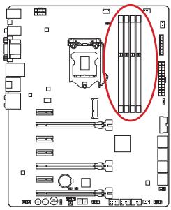
| DIMM1~4 | DDR3 Memory Slots | En-13 |
| FASTB1 | GO2BIOS Button | En-27 |
| FV1 | V-Check Connectors | En-25 |
| JAUD1 | Front Panel Audio Connector | En-24 |
| JBAT1 | Clear CMOS Jumper | En-28 |
| JCI1 | Chassis Intrusion Connector | En-22 |
| JCOM1 | Serial Port Connector | En-23 |
| JFP1, JFP2 | System Panel Connectors | En-20 |
| JPWR1~2 | ATX Power Connectors | En-15 |
| JTPM1 | TPM Module Connector | En-23 |
| JUSB1~3 | USB 2.0 Expansion Connector | En-21 |
| JUSB4 | USB 3.0 Expansion Connector | En-22 |
| MSATA_1 | mSATA Slot | En-24 |
| MULTI BIOS SWITCH | Multi-BIOS Switch | En-29 |
| OC_SWITCH1 | OC Genie Mode Switch | En-30 |
| OC1 | OC Genie Button | En-26 |
| PCI_E1~7 | PCIe Expansion Slot | En-16 |
| POWER1 | Power Button | En-27 |
| RESET1 | Reset Button | En-27 |
| SATA1~8 | SATA Connector | En-18 |
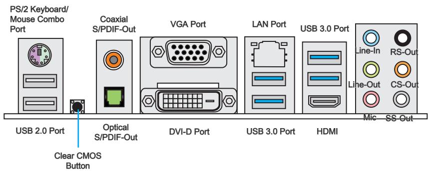
PS/2 Keyboard/Mouse Combo Port
A combination of PS/2® mouse/keyboard DIN connector for a PS/2® mouse/keyboard.
USB 2.0 Port
The USB 2.0 port is for attaching USB 2.0 devices such as keyboard, mouse, or other USB 2.0-compatible devices.
Clear CMOS Button
There is CMOS RAM present on board that is powered by an external battery to store system configuration data. Using CMOS RAM, the system can automatically boot into the operating system (OS) every time it is turned on. If you wish to clear the system configuration, press the button to clear the data.
Coaxial S/PDIF-Out
This S/PDIF (Sony & Philips Digital Interconnect Format) connector is provided for digital audio transmission to external speakers through an coaxial cable.
Optical S/PDIF-Out
This S/PDIF (Sony & Philips Digital Interconnect Format) connector is provided for digital audio transmission to external speakers through an optical fiber cable.
VGA Port
The DB15-pin female connector is provided for monitor.
DVI-D Port
The DVI-D (Digital Visual Interface-Digital) connector can be connected to a LCD monitor, or a CRT monitor with an adapter. To connect a monitor, please refer to the monitor's manual for more information.
USB 3.0 Port
USB 3.0 port is backward-compatible with USB 2.0 devices. It supports data transfer rate up to 5 Gbit/s (SuperSpeed).

Important
In order to use USB 3.0 devices, you must connect to a USB 3.0 port. If a USB cable is used, it must be USB 3.0 compliant.
LAN Port
The standard RJ-45 LAN jack is for connecting to a Local Area Network (LAN).
| LINK/ACT LED SPEED LED | LED | LED Status | Description |
| Link/ Activity LED | Off | No link | |
| Yellow | Linked | ||
| Blinking | Data activity | ||
| Speed LED | Off | 10 Mbps connection | |
| Green | 100 Mbps connection | ||
| Orange | 1 Gbps connection |
HOMI
HDMI Port HIGH-DEFINITION MULTIMEDIA INTERFACE
The High-Definition Multimedia Interface (HDMI) is an all-digital audio-video interface that is capable of transmitting uncompressed streams. HDMI supports all types of TV formats, including standard, enhanced, or high-definition video, plus multi-channel digital audio on a single cable.

Important
This platform supports dual-display and triple-display function.
| HDMI+VGA | HDMI+DVI | VGA+DVI | HDMI+VGA+DVI | |
| Extend mode (Extend the desktop to the second and thired monitor) | ○ | ○ | ○ | ○ |
| Clone mode (Monitors have the same screen) | ○ | ○ | ○ | ○ |
Audio Ports
These connectors are used for audio devices. The color of the jack refers to the function of the connector.
Blue-Line in: Used for connecting external audio outputting devices.
- Green- Line out: Used as a connector for speakers or headphone.
Pink-Mic: Used as a connector for a microphone.
- Black- RS-Out: Rear surround sound line out in 4/5.1/7.1 channel mode.
Orange-CS-Out: Center/subwoofer line out in 5.1/7.1 channel mode.
Gray-SS-Out: Side surround sound line out in 7.1 channel mode.
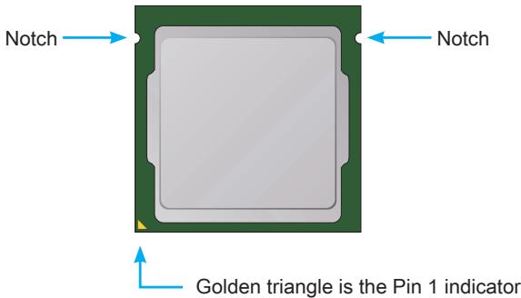
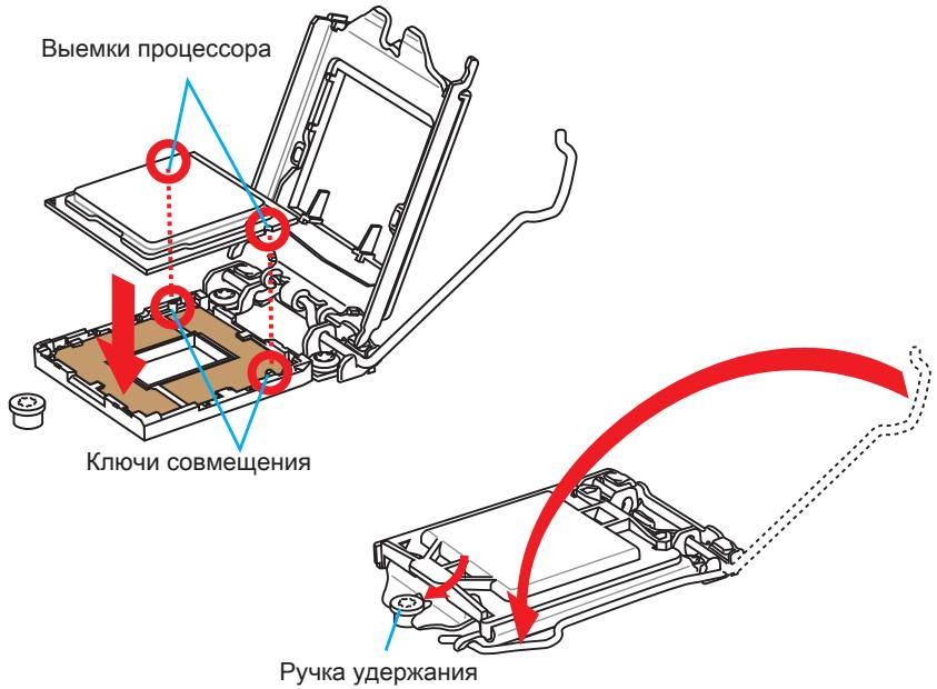
Introduction to the LGA 1150 CPU
The surface of the LGA 1150 CPU has two notches and a golden triangle to assist in correctly lining up the CPU for motherboard placement. The golden triangle is the Pin 1 indicator.

Important
Overheating
Overheating can seriously damage the CPU and motherboard. Always make sure the cooling fans work properly to protect the CPU from overheating. Be sure to apply an even layer of thermal paste (or thermal tape) between the CPU and the heatsink to enhance heat dissipation.
Replacing the CPU
When replacing the CPU, always turn off the system's power supply and unplug the power supply's power cord to ensure the safety of the CPU.
Overclocking
This motherboard is designed to support overclocking. Before attempting to overclock, please make sure that all other system components can tolerate overclocking. Any attempt to operate beyond product specifications is not recommend. MSI does not guarantee the damages or risks caused by inadequate operation beyond product specifications.
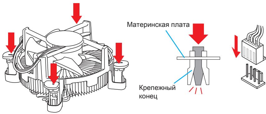
CPU & Heatsink Installation
When installing a CPU, always remember to install a CPU heatsink. A CPU heatsink is necessary to prevent overheating and maintain system stability. Follow the steps below to ensure correct CPU and heatsink installation. Wrong installation can damage both the CPU and the motherboard.

Video Demonstration
Watch the video to learn how to install CPU & heatsink. at the address below.
http://youtu.be/bf5La099url

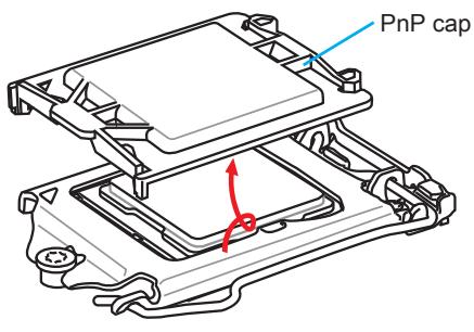
- Push the load lever down to unclip it and lift to the fully open position.
- The load plate will automatically lift up as the load lever is pushed to the fully open position.
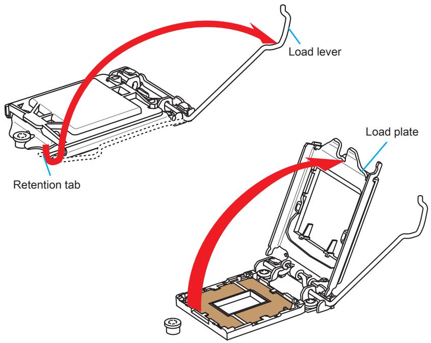

Important
Do not touch the socket contacts or the bottom of the CPU.
- Align the notches with the socket alignment keys. Lower the CPU straight down, without tilting or sliding the CPU in the socket. Inspect the CPU to check if it is properly seated in the socket.
- Close and slide the load plate under the retention knob. Close and engage the load lever.
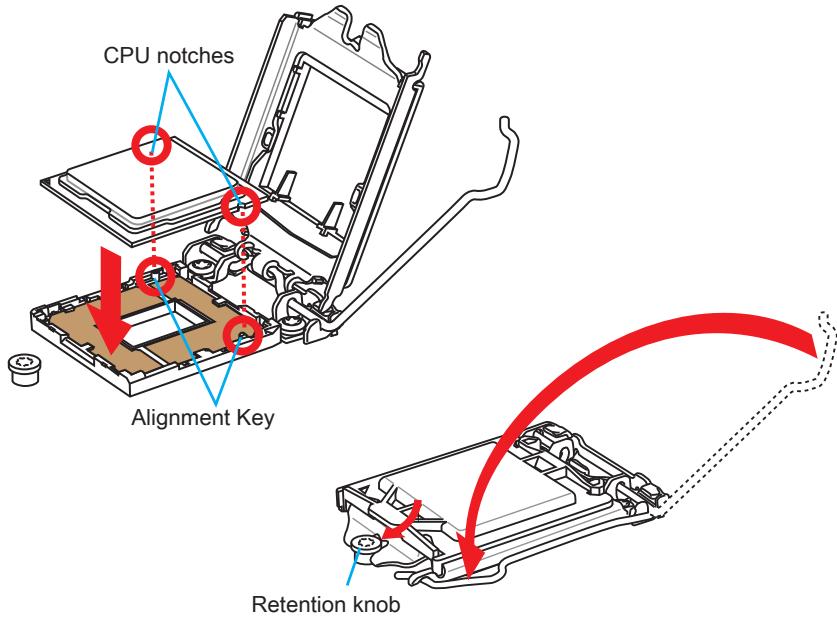
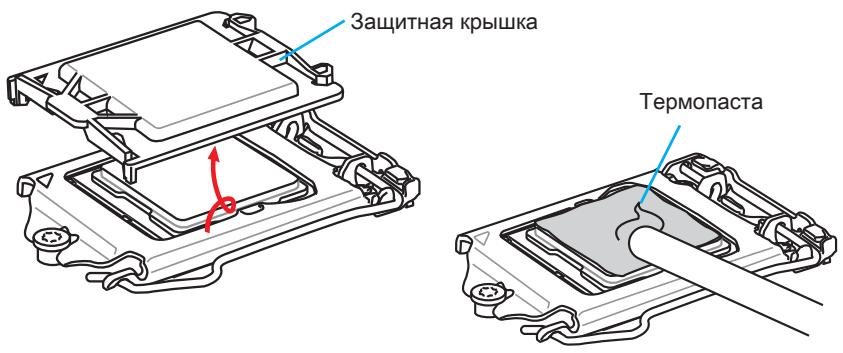
- When you press down the load lever the PnP cap will automatically pop up from the CPU socket. Do not discard the PnP cap. Always replace the PnP cap if the CPU is removed from the socket.
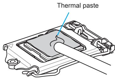
- Evenly spread a thin layer of thermal paste (or thermal tape) on the top of the CPU. This will help in heat dissipation and prevent CPU overheating.
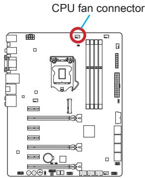
- Locate the CPU fan connector on the motherboard.
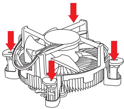
- Place the heatsink on the motherboard with the fan's cable facing towards the fan connector and the fasteners matching the holes on the motherboard.
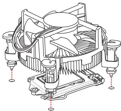
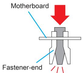
- Push down the heatsink until the four fasteners get wedged into the holes on the motherboard. Press the four fasteners down to fasten the heatsink. As each fastener locks into position a click should be heard.
- Inspect the motherboard to ensure that the fastener-ends have been properly locked in place.
- Finally, attach the CPU fan cable to the CPU fan connector on the motherboard.

Important
- Confirm that the CPU heatsink has formed a tight seal with the CPU before booting your system.
- Whenever the CPU is not installed, always protect the CPU socket pins by covering the socket with the plastic cap.
- If you purchased a separate CPU and heatsink/ cooler, Please refer to the documentation in the heatsink/ cooler package for more details about installation.
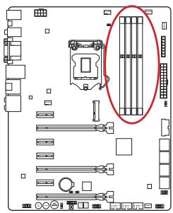
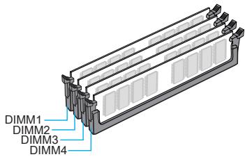
Memory
These DIMM slots are used for installing memory modules. For more information on compatible components, please visit http://www.msi.com/service/test-report/


Video Demonstration
Watch the video to learn how to install memories at the address below. http://youtu.be/76yLtJaKICQ

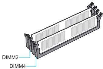
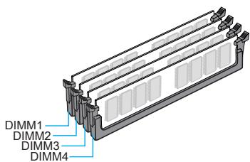
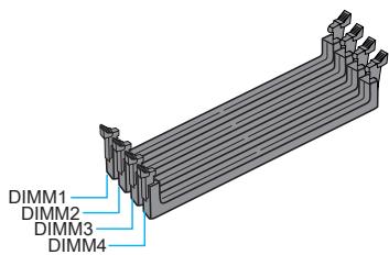
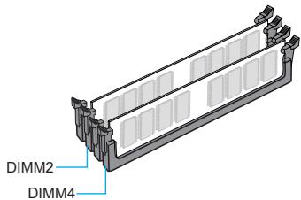
Dual-Channel mode Population Rule
In Dual-Channel mode, the memory modules can transmit and receive data with two data bus channels simultaneously. Enabling Dual-Channel mode can enhance system performance. The following illustrations explain the population rules for Dual-Channel mode.

Important
- DDR3 memory modules are not interchangeable with DDR2, and the DDR3 standard is not backward compatible. Always install DDR3 memory modules in DDR3 DIMM slots.
- To ensure system stability, memory modules must be of the same type and density in Dual-Channel mode.
- Due to chipset resource usage, the system will only detect up to 31+ GB of memory (not full 32 GB) when all DIMM slots have 8GB memory modules installed.
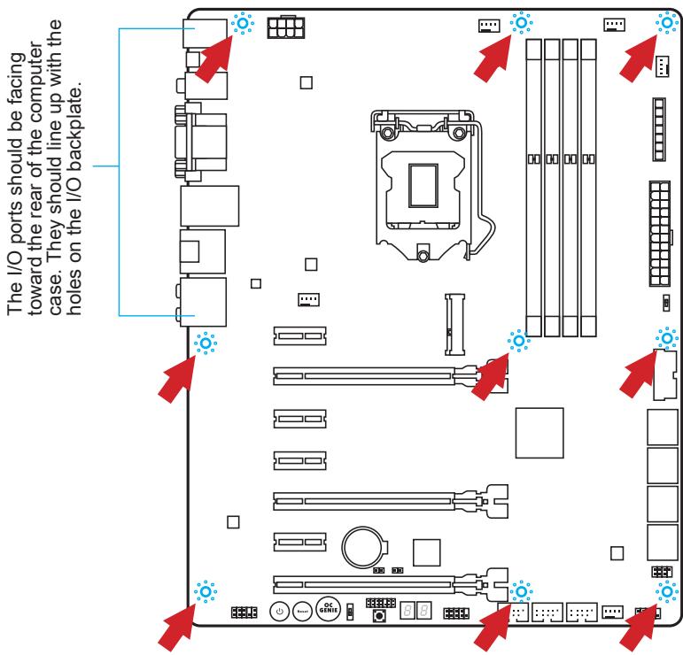
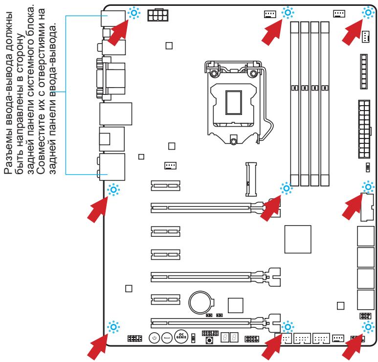
Mounting Screw Holes
When installing the motherboard, first install the necessary mounting stands required for an motherboard on the mounting plate in your computer case. If there is an I/O back plate that came with the computer case, please replace it with the I/O backplate that came with the motherboard package. The I/O backplate should snap easily into the computer case without the need for any screws. Align the mounting plate's mounting stands with the screw holes on the motherboard and secure the motherboard with the screws provided with your computer case. The locations of the screw holes on the motherboard are shown below. For more information, please refer to the manual that came with the computer case.

Important
- Install the motherboard on a flat surface free from unnecessary debris.
- To prevent damage to the motherboard, any contact between the motherboard circuitry and the computer case, except for the mounting stands, is prohibited.
- Please make sure there are no loose metal components on the motherboard or within the computer case that may cause a short circuit of the motherboard.

Video Demonstration
Watch the video to learn how to install power supply connectors. http://youtu.be/gkDYyR_8314

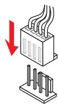
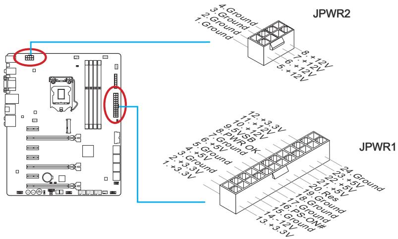
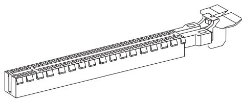
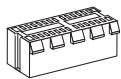
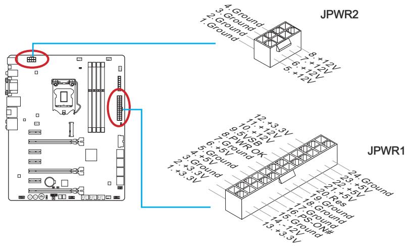
JPWR1~2:ATX Power Connectors
These connectors allow you to connect an ATX power supply. To connect the ATX power supply, align the power supply cable with the connector and firmly press the cable into the connector. If done correctly, the clip on the power cable should be hooked on the motherboard's power connector.

Important
Make sure that all the power cables are securely connected to a proper ATX power supply to ensure stable operation of the motherboard.
Expansion Slots
This motherboard contains numerous slots for expansion cards, such as discrete graphics or audio cards.
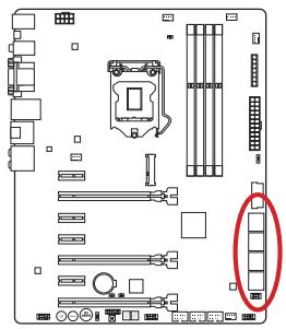
PCI_E1~7:PCIe Expansion Slot
The PCIe slot supports the PCIe interface expansion card.
PCIe 3.0 x16 Slot
PCIe 2.0 x1 Slot

Important
When adding or removing expansion cards, always turn off the power supply and unplug the power supply power cable from the power outlet. Read the expansion card's documentation to check for any necessary additional hardware or software changes.
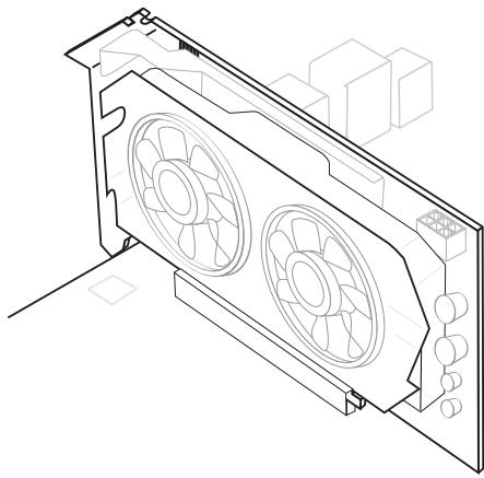
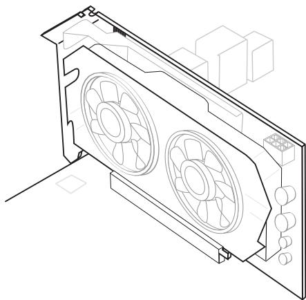
If available, this motherboard takes advantage of the CPU's integrate graphics processor, but discrete video cards can be installed by way of the motherboard's expansion slots. Adding on one or more discrete video cards will significantly boost the system's graphics performance. For best compatibility, MSI graphics cards are recommended.

Video Demonstration
Watch the video to learn how to install a graphics card on PCIe x16 slot with butterfly lock.
http://youtu.be/mG0GZpr9w_A

Single Video Card Installation
- Determine what type of expansion slot(s) the video card will use. Locate the expansion slot(s) on the motherboard. Remove any protective expansion slot covers from the computer case.
- Line up the video card on top of the expansion slot(s) with the display ports facing out of the computer case. For a single video card installation, using the PCI_E2 slot is recommended.
- Push the video card into its expansion slot(s). Depending on the expansion slot(s) used, there should be clip(s) on the expansion slot(s) that will lock in place.
- If needed, screw the edge of the graphics card to the computer case. Some video cards might require a power cable directly from the power supply.
- Please consult your video card's manual for further instructions regarding driver installation or other special settings.
SATA1~8: SATA Connector
This connector is a high-speed SATA interface port. Each connector can connect to one SATA device. SATA devices include disk drives (HDD), solid state drives (SSD), and optical drives (CD/DVD/Blu-Ray).

Video Demonstration
Watch the video to learn how to Install SATA HDD. http://youtu.be/RZsMpqxthyc

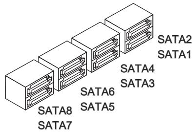
SATA1~6 (6Gb/s, by Intel® Z87)
SATA7~8 (6Gb/s, by ASMedia® ASM1061)

Important
- The SATA6 port will be unavailable when install a SSD in the mSATA port.
- Many SATA devices also need a power cable from the power supply. Such devices include disk drives (HDD), solid state drives (SSD), and optical drives (CD / DVD / Blu-Ray). Please refer to the device's manual for further information.
- Many computer cases also require that large SATA devices, such as HDDs, SSDs, and optical drives, be screwed down into the case. Refer to the manual that came with your computer case or your SATA device for further installation instructions.
- Please do not fold the SATA cable at a 90-degree angle. Data loss may result during transmission otherwise.
- SATA cables have identical plugs on either sides of the cable. However, it is recommended that the flat connector be connected to the motherboard for space saving purposes.
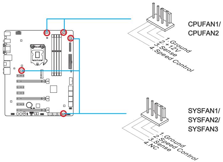
CPUFAN1~2,SYSFAN1~3: Fan Power Connectors
The fan power connectors support system cooling fans with +12V. If the motherboard has a System Hardware Monitor chipset on-board, you must use a specially designed fan with a speed sensor to take advantage of the CPU fan control. Remember to connect all system fans. Some system fans may not connect to the motherboard and will instead connect to the power supply directly. A system fan can be plugged into any available system fan connector.

Important
- Please refer to your processor's official website or consult your vendor to find recommended CPU heatsink.
- These connectors support Smart Fan Control with liner mode. The Command Center utility can be installed to automatically control the fan speeds according to the CPU's and system's temperature.
- If there are not enough ports on the motherboard to connect all system fans, adapters are available to connect a fan directly to a power supply.
- Before first boot up, ensure that there are no cables impeding any fan blades.
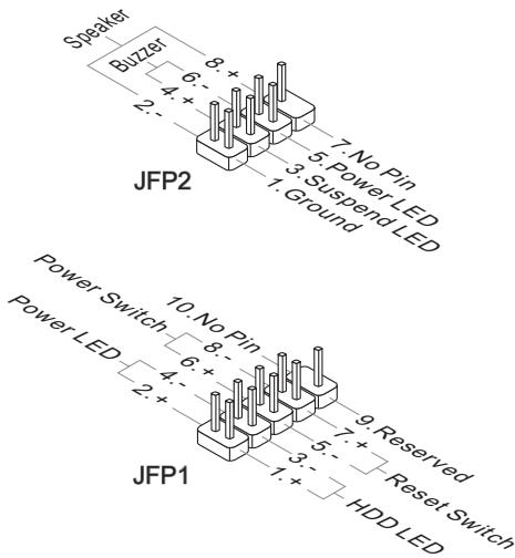
JFP1, JFP2: System Panel Connectors
These connectors connect to the front panel switches and LEDs. The JFP1 connector is compliant with the Intel® Front Panel I/O Connectivity Design Guide. When installing the front panel connectors, please use the optional M-Connector to simplify installation. Plug all the wires from the computer case into the M-Connector and then plug the M-Connector into the motherboard.

Video Demonstration
Watch the video to learn how to Install front panel connectors. http://youtu.be/DPELIdVNZUI


Important
- On the connectors coming from the case, pins marked by small triangles are positive wires. Please use the diagrams above and the writing on the optional M-Connectors to determine correct connector orientation and placement.
- The majority of the computer case's front panel connectors will primarily be plugged into JFP1.
JUSB1~3: USB 2.0 Expansion Connector
This connector is designed for connecting high-speed USB peripherals such as USB HDDs, digital cameras, MP3 players, printers, modems, and many others.
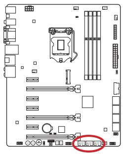
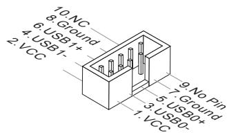
The JUSB1 (red mark) connector supports MSI's new SuperCharger technology which provides quicker USB charging of your cellular phone or other USB-powered devices. To enable this feature, please install the MSI SuperCharger application on your computer. When the SuperCharger application is turned on, the JUSB1 connector will convert data channels to extra power channels to quickly charge your connected device. Please note that when the SuperCharger application is turned on, data transmission and synchronization over the JUSB1 connector will not function. To enable the JUSB1 connector to function as a normal USB 2.0 connector, please turn off the SuperCharger application. When the computer is in stand-by or hibernation mode (S3/ S4/ S5) SuperCharger mode will automatically be enabled.

Important
- Note that the VCC and GND pins must be connected correctly to avoid possible damage.
- Please only connect one device per USB port to ensure stable charging.
- SuperCharger Technology is only available on select MSl motherboard models. Please refer to the MSl website to check if your motherboard has SuperCharger technology.
- For iPad, JUSB1 (red mark) can still charge iPad in S3, S4, S5 state.
- We recommend that don't disconnect the device when you charge it in S1 state.
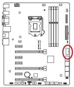
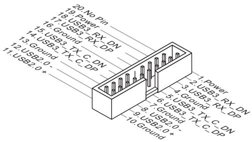
JUSB4: USB 3.0 Expansion Connector
The USB 3.0 port is backwards compatible with USB 2.0 devices. It supports data transfer rates up to 5Gbits/s (SuperSpeed).

Important
- Note that the VCC and GND pins must be connected correctly to avoid possible damage.
- To use a USB 3.0 device, you must connect the device to a USB 3.0 port through an optional USB 3.0 compliant cable.
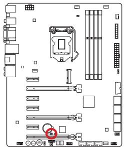
JCI1: Chassis Intrusion Connector
This connector connects to the chassis intrusion switch cable. If the computer case is opened, the chassis intrusion mechanism will be activated. The system will record this intrusion and a warning message will flash on screen. To clear the warning, you must enter the BIOS utility and clear the record.
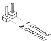
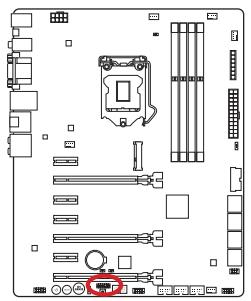
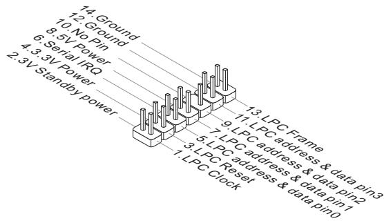
JTPM1: TPM Module Connector
This connector connects to a TPM (Trusted Platform Module). Please refer to the TPM security platform manual for more details and usages.
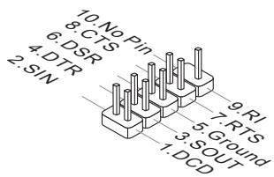
JCOM1: Serial Port Connector
This connector is a 16550A high speed communication port that sends/receives 16 bytes FIFOs. You can attach a serial device.
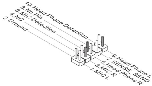
JAUD1: Front Panel Audio Connector
This connector allows you to connect the front audio panel located on your computer case. This connector is compliant with the Intel® Front Panel I/O Connectivity Design Guide.
MSATA_1: mSATA Slot
The mSATA slot is for mSATA interface solid state drives (SSD).

Important
The SATA6 port will be unavailable when install a SSD in the mSATA port.
These voltage checkpoints are used to measure the current system voltages. A multimeter (not included) will be required to check voltages.
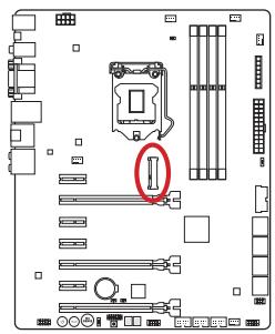
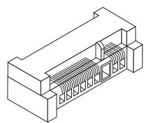
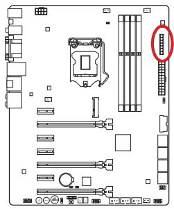
FV1: V-Check Connectors
To check the voltage, please use the optional voltage checkpoint cables included in the motherboard package. Attach the positive lead of the multimeter to the voltage checkpoint cable and the negative lead to the ground connector.
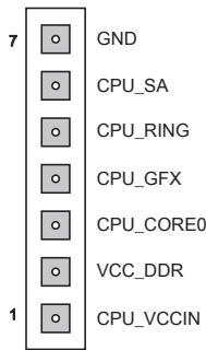
| Connector | Description |
| GND (pin 7) | Ground |
| CPU_SA (pin 6) | The CPU_SA (CPU System Agent) voltage is the voltage supplied to the integrated memory controller inside the CPU. |
| CPU_RING (pin 5) | The CPU Ring is an interface for integrated controllers inside the CPU. The CPU Ring voltage can affect the CPU overclocking performance. |
| CPU_GFX (pin 4) | The CPU_GFX voltage is the voltage supplied to the integrated graphics processor located on the CPU. |
| CPU_CORE0 (pin 3) | CPU core0 voltage. The CPU voltage is the voltage supplied to the CPU core. Higher overclocks may require higher CPU core voltages to maintain stability. |
| VCC_DDR (pin 2) | Memory voltage. The DDR memory voltage is the voltage supplied to the DDR memory modules on the motherboard. Lower memory timings may require higher voltages to maintain system stability. |
| CPU_VCCIN (pin1) | The CPU VCCIN voltage is the CPU power source that is shared with components of the CPU. |
The motherboard has numerous on-board buttons to control various functions. This section will explain how to change your motherboard's functions through the use of these on-board buttons.
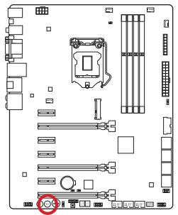
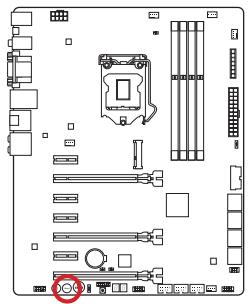
OC1: OC Genie Button
This button is used to automatically overclock the system. Press this button once while the system is off to enable OC Genie. The button will lock remain depressed until it is pushed again to disable OC Genie. On the next boot, the OC Genie utility will automatically overclock the CPU settings to optimal performance values. To disable OC Genie, power off the system and press the OC Genie button again. The button will depress and the CPU configuration settings will return to normal values.

On

Off

Important
- This motherboard provides two ways to enable OC Genie: press the physical OC Genie button on the motherboard, or click the virtual OC Genie button in BIOS. You can specify how OC Genie to be enabled by using the "OC Genie Function Control" item in BIOS.
- Please install DDR3 1333 or faster memory and equip a better heatsink/ cooler to use the OC Genie function.
- We do not guarantee the OC Genie overclocking range or the damages/risks caused by overclocking behavior.
- It is possible to disable the OC Genie function in the BIOS setup. Please refer to the BIOS section of the manual for instructions on how to turn off OC Genie from the BIOS.
- The usage of OC Genie is at the user's own risk. Overclocking is never guaranteed by MSI.
To ensure successfully OC Genie usage, MSI components are recommended.
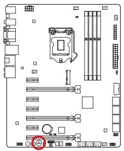
POWER1:PowerButton
This button is used to turn-on and turn-off the system. Press the button once to turn-on or turn-off the system.
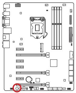

RESET1: Reset Button
This reset button is used to reset the system. Press the button to reset the system.

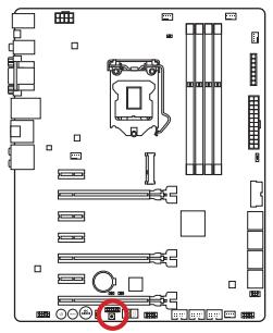
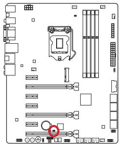
FASTB1: GO2BIOS Button
If you enable the "MSI Fast Boot" feature in BIOS, the keyboard will be unavailable and entering BIOS Setup by pressing DEL will not function. Therefore, you can press this button to enter BIOS Setup after reboot.

JBAT1: Clear CMOS Jumper
There is CMOS RAM onboard that is external powered from a battery located on the motherboard to save system configuration data. With the CMOS RAM, the system can automatically boot into the operating system (OS) every time it is turned on. If you want to clear the system configuration, set the jumpers to clear the CMOS RAM.

Keep Data

Clear Data

Important
You can clear the CMOS RAM by shorting this jumper while the system is off. Afterwards, open the jumper. Do not clear the CMOS RAM while the system is on because it will damage the motherboard.
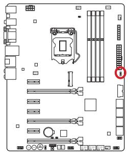
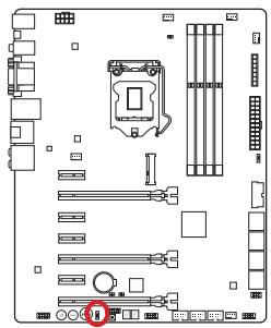
MULTI BIOS SWITCH: Multi-BIOS Switch
This motherboard has two built-in BIOS ROMs (Labeled A and B, default BIOS ROM is A). If one is crashed, you can shift to the other for booting by sliding the switch. In addition, these two BIOS ROMs do not have the Auto Recovery feature, you need to maintain or update the BIOS version by yourself.

BIOS recovery using the M-flash utility:
- Ensure that the system is switched off.
- Boot up the system with the operational BIOS ROM by switching the Multi-BIOS switch.
- Enter the BIOS setup M-Flash Save BIOS to storage and then save the file to a bootable USB drive disk (root folder)..
- Switch back to the BIOS ROM that needs to be recovered.
- Choose "Select one file to update BIOS" and recover the BIOS ROM with the file saved in the USB pen drive.

Important
Do not use the Multi-BIOS switch when system is booting up.
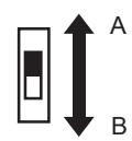
OC_SWITCH1: OC Genie Mode Switch
This switch provides two overclocking modes (Turbo Mode and Gaming Mode) for OC Genie operation. When you press the OC Genie button, the overclocking procedure will be performed according to the setting of this switch. The Turbo Mode is the default setting. The Gaming Mode allows the OC Genie function to overclock the CPU/ system frequency higher than Turbo Mode.
Gear 2
Gear 1
(Default)


Red LED

Blue LED
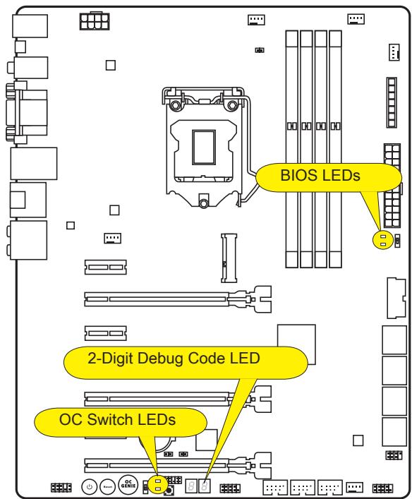
BIOS LEDs
These LEDs are used to distinguish BIOS A or B in operation.
When the top LED lights blue, the BIOS A is in operation.
When the bottom LED lights green, the BIOS B is in operation.
OC Switch LEDs
These LEDs are used to indicate OC Genie operation mode.
When the top LED lights red, the OC Genie operation mode is Gear 2.
When the bottom LED lights blue, the OC Genie operation mode is Gear 1.
Debug Code LED Table
Please refer to the table below to get more information about the Debug Code LED message.
| Post | Status |
| 02,07 | Power on CPU Initialization |
| 03,08 | Power on North Bridge Initialization |
| 04,09 | Power on South Bridge Initialization |
| 0B | Power on Cache Initialization |
| 11~14,32~36,56~5A | Early CPU Initialization |
| 15~18,37~3A | Early North Bridge Initialization |
| 19~1C,3B~3E | Early South Bridge Initialization |
| 1D~2F,31,3F~4E,50~55 | Early Memory Initialization |
| 63~67,D0 | Late CPU Initialization |
| 69~6F,D1 | Late North Bridge Initialization |
| 70~77,D2 | Late South Bridge Initialization |
| 92~96,B5,D4 | PCI bus Initialization |
| 97,98,99,B2,D5~D7 | Console Output/Input devices/Console initialization and Load Option ROM (VGA, RAID, parallel ports, serial ports......) |
| 9A~A7,B4 | Onboard devices Initialize and Detect (USB/ SATA/ SCSI......) |
| A8,A9,AB | Start of Setup. BIOS setup if needed/ requested. |
| AD/AE | Ready To Boot event/Legacy Boot event |
After you install the operating system you will need to install drivers to maximize the performance of the new computer you just built. MSI motherboard comes with a Driver Disc. Drivers allow the computer to utilize your motherboard more efficiently and take advantage of any special features we provide.
You can protect your computer from viruses by installing the bundled security program. The bundle also includes a variety of powerful and creative utilities.
Total Installer
Total Installer is very easy to use and does a great job of finding necessary drivers. Please follow the steps below to install drivers and utilities for your new computer.
- Insert MSI Driver Disc into the optical drive. The setup screen will automatically appear if autorun is enabled in OS.
- Click Total Installer. A popup dialogue will appear listing all necessary drivers.
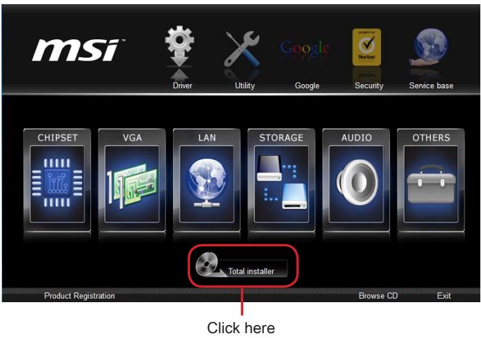
- Select all checkbox on driver listing dialog.
- Click Install button.
- The software installation will then be in progress, after it has finished it will prompt you to restart.
- Click OK button to finish.
- Restart your computer.
You can also use the same method to install the utilities.
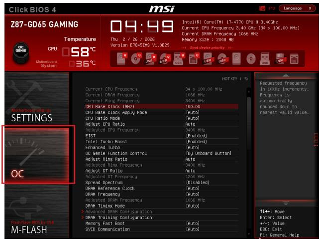
CLICK BIOS is developed by MSI that provides a graphical user interface for setting parameters of BIOS by using the mouse and the keyboard.
With the CLICK BIOS, users can change BIOS settings, monitor CPU temperature, select the boot device priority and view system information such as the CPU name, DRAM capacity, the OS version and the BIOS version. Users can import and export parameters data for backup or sharing with friends.
Entering BIOS Setup
Power on the computer and the system will start the Power On Self Test (POST) process. When the message below appears on the screen, please key to enter BIOS:
Press DEL key to enter Setup Menu, F11 to enter Boot Menu
If the message disappears before you respond and you still need to enter BIOS, restart the system by turning the computer OFF then back ON or pressing the RESET button. You may also restart the system by simultaneously pressing <Ctrl> , <Alt> , and <Delete> keys.
MSI additionally provides two methods to enter the BIOS setup. You can click the "GO2BIOS" tab on "MSI Fast Boot" utility screen or press the physical "GO2BIOS" button (optional) on the motherboard to enable the system going to BIOS setup directly at next boot.
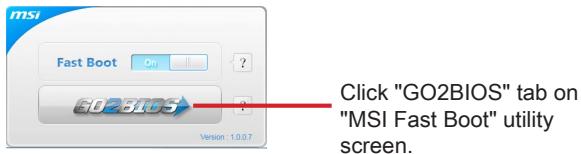

Important
- Please be sure to install the "MSI Fast Boot" utility before using it to enter the BIOS setup.
- The items under each BIOS category described in this chapter are under continuous update for better system performance. Therefore, the description may be slightly different from the latest BIOS and should be held for reference only.
After entering BIOS, the following screen is displayed.
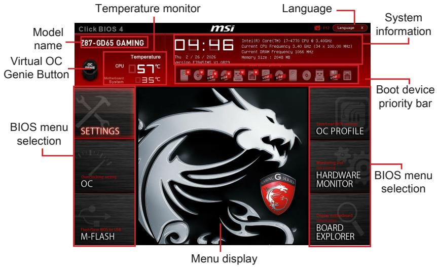
Temperature monitor
Shows the temperatures of the processor and the motherboard.
Language
Allows you to select the language of the BIOS setup.
System information
Shows the time, date, CPU name, CPU frequency, DRAM frequency, DRAM capacity and the BIOS version.
BIOS menu selection
The following options are available:
- SETTINGS - Uses this menu to specify the parameters for chipset and boot devices.
- OC - This menu contains the frequency and voltage adjustments. Increasing the frequency can get better performance, however high frequency and heat can cause instability, we do not recommend general users to overclock.
- M-FLASH - This menu provides the way to update BIOS with a USB flash disk.
- OC PROFILE -This menu is used to set various overlapping profiles.
- HARDWARE MONITOR - This menu is used to set the speeds of fans and monitor voltages of system.
BOARD EXPLORER - It will provide the information of the installed devices on the motherboard.
Boot device priority bar
You can move the device icons to change the boot priority.

High priority
Low priority
Menu display
This area provides BIOS settings and information to be configured.
Virtual OC Genie Button
Enables or disables the OC Genie function by clicking on this button. When enabled, this button will be light. Enabling OC Genie function can automatically overclock with MSI optimized overclocking profile.
Model Name
Shows the model name of motherboard.

Sub-menu
If you find a point symbol to the left of certain items, that means a sub-menu can be launched for additional options. You can use the arrow keys or mouse to highlight the item and press
▶ Scroll bar
Slide the scroll bar or use the arrow keys to display the other items that are available on the "menu display" area.
General Help
The General Help displays a brief description to assist you in grasping the selected item.
Operation
You can control BIOS settings with the mouse and the keyboard. The following table lists and describes the hot keys and the mouse operations.
| Hot key | Mouse | Description |
| <↑↓→←> | Move the cursor | Select Item |
| <Enter> | Click/ Double-click the left button | Select Icon/ Field |
| <Esc> | Click the right button | Jump to the Exit menu or return to the previous from a submenu |
| <++> | Increase the numeric value or make changes | |
| <-> | Decrease the numeric value or make changes | |
| <F1> | General Help | |
| <F4> | CPU Specifications | |
| <F5> | Enter Memory-Z | |
| <F6> | Load optimized defaults | |
| <F8> | OC Profile Load From USB | |
| <F9> | OC Profile Save to USB | |
| <F10> | Save Change and Reset | |
| <F12> | Save a screenshot to a FAT/FAT32 USB drive |
OC Menu
This menu is for advanced users who want to overclock the mainboard.

Important
- Overclocking your PC manually is only recommended for advanced users.
- Overclocking is not guaranteed, and if done improperly, can void your warranty or severely damage your hardware.
- If you are unfamiliar with overclocking, we advise you to use OC Genie for easy overclocking.
Current CPU/DRAM/Ring Frequency
These items show the current frequencies of installed CPU, Memory and Ring. Read-only.
CPU Base Clock (MHz) [Default]
Sets the CPU Base clock. You may overclock the CPU by adjusting this value. Please note that overclocking behavior and stability is not guaranteed. This item appears when the installed processor supports this function.
Current CPU Base Clock Strap
Shows the current CPU Base Clock Strap. Read only. This item can only be changed if the processor supports this function.
Adjust CPU Base Clock Strap [Auto]
Sets the CPU Base Clock Strap. You may overclock the CPU Base Clock by adjusting this value. Please note that overclocking behavior and stability is not guaranteed. This item can only be changed if the processor supports this function. If set to "Auto", BIOS will configure this setting automatically. [Options: Auto, 1.00, 1.25, 1.67]
CPU Base Clock Apply Mode [Auto]
Sets the applying mode for adjusted CPU base clock.
[Auto] This setting will be configured automatically by BIOS.
[Next Boot] CPU will run the adjusted CPU base clock after reboot.
[Immediate] CPU runs the adjusted CPU base clock immediately.
- CPU PCIE PLL [Auto]
Selects a PLL (Phase Lock Loop) mode for CPU PCIe. This item appears when the installed CPU supports this setting.
[Auto] This setting will be configured automatically by BIOS.
[LC PLL] Enables LC PLL for normal usage.
[S BPLL] Enables SB PLL for extreme overclocking.
Filter PLL [Auto]
Enables or disables the filter PLL for CPU. This item appears when the installed CPU supports this setting.
[Auto] This setting will be configured automatically by BIOS.
[Enabled] Provides wide range of base clock for overclocking when base clock strap be set to higher value.
[Disabled] Provides normal range of base clock.
CPU Ratio Mode [Auto]
Selects the CPU Ratio operating mode.
[Auto] This setting will be configured automatically by BIOS.
[Fixed Mode] Fits the CPU ratio.
[Dynamic Mode] CPU ratio will be changed dynamically according to the CPU loading.
Adjust CPU Ratio [Auto]
Sets the CPU ratio that is used to determine CPU clock speed. This item can only be changed if the processor supports this function.
Adjusted CPU Frequency
Shows the adjusted CPU frequency. Read-only.
EIST [Enabled]
Enables or disables the Enhanced Intel® SpeedStep Technology.
Intel Turbo Boost [Enabled]
Enables or disables the Intel® Turbo Boost. This item appears when the installed CPU supports this function.
[Enabled] Enables this function to boost CPU performance automatically above rated specifications when system request the highest performance state.
[Disabled] Disables this function.
Enhanced Turbo [Auto]
Enables or disables Enhanced Turbo function for all CPU cores to boost CPU performance.
[Auto] This setting will be configured automatically by BIOS.
[Enabled] All CPU cores would be increased to maximum turbo ratio.
[Disabled] Disables this function.
OC Genie Function Control [By Onboard Button]
Enables the OC Genie function by virtual button in BIOS or physical button on motherboard. Enabling OC Genie function can automatically overclock the system with MSI optimized overclocking profile.
[By BIOS Options] OC Genie function is enabled by clicking the virtual OC Genie button at the top left corner of BIOS setup screen.
[By Onboard Button]OC Genie function is enabled by pressing the physical OC Genie button on the motherboard.
OC Genie Switch [Gear1]
Selects a kind of overclocking profiles for OC Genie Function. This item appears when "OC Genie Function Control" sets to [By BIOS Options].
[Gear1] Enables Gear1 overclocking profile for overclocking.
[Gear2] Enables Gear2 overclocking profile for extreme overclocking.
![MSI Z87-GD65 - OC Genie Function Control [By Onboard Button] - 1](/content/2019/11/138342/images/a126512205968c3a9c1b0cb01dc4babc8111f30fa9ec091b55975d022dcc76c5.jpg)
Important
- We recommend that you do not to make any modification in OC menu and do not to load defaults after enabling the OC Genie function.
- Updating BIOS or clearing CMOS is not allowed in OC Genie mode, and it may cause OC Genie function fail or other effect.
Adjust Ring Ratio [Auto]
Sets the ring ratio. The valid value range depends on the installed CPU.
Adjusted Ring Frequency
Shows the adjusted Ring frequency. Read-only.
Adjust GT Ratio [Auto]
Sets the integrated graphics ratio. The valid value range depends on the installed CPU.
Adjusted GT Frequency
Shows the adjusted integrated graphics frequency. Read-only.
DRAM Reference Clock [Auto]
Sets the DRAM reference clock. The valid value range depends on the installed CPU. This item appears when a CPU that supports this adjustment is installed.
DRAM Frequency [Auto]
Sets the DRAM frequency. Please note the overclocking behavior is not guaranteed.
Adjusted DRAM Frequency
Shows the adjusted DRAM frequency. Read-only.
Extreme Memory Profile (X.M.P) [Disabled]
X.M.P. (Extreme Memory Profile) is the overclocking technology by memory module.
This item will be available when you install the memory modules that support X.M.P. technology.
[Disabled] Disables this function.
[Profile 1] Uses profile1 over-clocking settings of installed XMP memory module.
[Profile 2] Uses profile2 over-clocking settings of installed XMP memory module.
DRAM Timing Mode [Auto]
Selects the memory timing mode.
[Auto] DRAM timings will be determined based on SPD (Serial Presence Detect) of installed memory modules.
[Link] Allows user to configure the DRAM timing manually for all memory channel.
[UnLink] Allows user to configure the DRAM timing manually for respective memory channel.
Advanced DRAM Configuration
Press
DRAM Training Configuration
Press
Memory Fast Boot [Auto]
Enables or disables the initiation and training for memory every booting.
[Auto] This setting will be configured automatically by BIOS.
[Enabled] Memory will completely imitate the archive of first initiation and first training. After that, the memory will not be initialized and trained when booting to accelerate the system booting time.
[Disabled] The memory will be initialized and trained every booting.
DigitALL Power
Press
CPU Phase Control [Auto]
Controls PWM phase proportionally to the CPU loading. If set to "Auto", BIOS will optimize the CPU PWM phase automatically.
[Auto] This setting will be configured automatically by BIOS.
[Disabled] Disables the PWM power phase switching feature.
CPU Vdroop Offset Control [Auto]
Sets a percentage of offset voltage for CPU vdroop. If set to "Auto", BIOS will configure this setting automatically. [Options: Auto, +12.5%, +25%, +37.5%, +50%, +62.5%, +75%, +87.5%, +100%]
CPU Over Voltage Protection [Auto]
Sets the voltage limit for CPU over-voltage protection. If set to "Auto", BIOS will configure this setting automatically. Higher voltage provides less protection and may damage the system.
CPU Under Voltage Protection [Auto]
Sets the voltage limit for CPU under-voltage protection. If set to "Auto", BIOS will configure this setting automatically. Higher voltage provides less protection and may damage the system.
CPU Over Current Protection [Auto]
Sets the current limit for CPU over-current protection. If set to "Auto", BIOS will configure this setting automatically. Higher percentage provides less protection and may damage the system.
CPU Switching Frequency [Auto]
Sets the PWM working speed to stabilize CPU Core voltage and minimize ripple range. Increasing the PWM working speed will cause higher temperature of MOSFET. So please make sure a cooling solution is well-prepared for MOSFET before you increase the value. If set to "Auto", BIOS will configure this setting automatically.
CPU VRM Over Temperature Protection [Enabled]
Enables or disables the CPU VRM over-temperature protection.
[Enabled] Sets the temperature limit on CPU VRM for over-temperature protection.
[Disabled] Disables this function.
CPU Power Duty Control
Selects the method of VRM control for component's phase.
[Thermal Balance] Control the VRM with thermal balance mode.
[Current Balance] Control the VRM with current balance mode.
SVID Communication [Auto]
Enables or disables SVID (Serial Voltage Identification) support.
[Auto] This setting will be configured automatically by BIOS.
[Enabled] PWM phase will be changed dynamically according to the CPU SVID (Serial Voltage Identification).
[Disabled] Disables SVID (Serial Voltage Identification) support.
VCCIN Voltage [Auto]
Sets the CPU input voltage. The CPU input voltage is the CPU power source that is shared with components of the CPU.
Current VCCIN Voltage
Shows current CPU VCCIN voltage. Read-only.
CPU Core Voltage Mode/ CPU Ring Voltage Mode/ CPU GT Voltage Mode [Auto]
Selects the control modes for these voltages.
[Auto] This setting will be configured automatically by BIOS.
[Adaptive Mode] Sets adaptive voltages automatically for optimizing the system performance.
[Override Mode] Allows you to set these voltages manually.
CPU Core Voltage/ CPU Ring Voltage/ CPU GT Voltage [Auto]
Sets these voltages. If set to "Auto", BIOS will set these voltages automatically or you can set it manually.
- CPU Core Voltage Offset Mode/ CPU Ring Voltage Offset Mode/ CPU GT Voltage Offset Mode/ CPU SA Voltage Offset Mode/ CPU IO Analog Voltage Offset Mode/ CPU IO Digital Voltage Offset Mode [Auto]
Selects the voltage offset modes.
[Auto] This setting will be configured automatically by BIOS.
[+] Allows you to set the positive offset voltage.
[-] Allows you to set the negative offset voltage.
- CPU Core Voltage Offset/ CPU Ring Voltage Offset/ CPU GT Voltage Offset/ CPU SA Voltage Offset/ CPU IO Analog Voltage Offset/ CPU IO Digital Voltage Offset [Auto]
Set the offset values for these voltages.
Current CPU Core Voltage/ Current CPU Ring Voltage/ Current CPU GT Voltage/ Current CPU SA Voltage/ Current CPU IO Digital Voltage
Show the current voltages. Read-only.
Internal VR OVP OCP Protection [Auto]
Enables or disables the over-voltage protection and over-current protection for CPU internal VR (Voltage Regulator).
[Auto] This setting will be configured automatically by BIOS.
[Enabled] Sets the voltage limit on the CPU internal VR for over-voltage protection and over-current protection.
[Disabled] Disables this function for overclocking.
Internal VR Efficiency Management [Auto]
Enables or disables the CPU internal VR efficiency management.
[Auto] This setting will be configured automatically by BIOS.
[Enabled] Enables the VR efficiency management for power-saving control.
[Disabled] Disables this function.
DRAM Voltage [Auto]
Sets the memory voltage. If set to "Auto", BIOS will set memory voltage automatically or you can set it manually.
Current DRAM Voltage
Shows current memory voltage. Read only.
- DDR_VREF_CA/ DDR_VREF_DQ_A/ DDR_VREF_DQ_B/ PCH 1.05 Voltage/ PCH 1.5 Voltage
Set these voltages. If set to "Auto", BIOS will set these voltages automatically or you can set it manually.
Current PCH 1.05 Voltage
Shows current PCH 1.05 voltage. Read only.
CPU Memory Changed Detect [Enabled]
Enables or disables the system to issue a warning message during boot when the CPU or memory has been replaced.
[Enabled] The system will issue a warning message during boot and then needs to load the default settings for new devices.
[Disabled] Disables this function and keeps the current BIOS settings.
Spread Spectrum
This function reduces the EMI (Electromagnetic Interference) generated by modulating clock generator pulses.
[Enabled] Enables the spread spectrum function to reduce the EMI (Electromagnetic Interference) problem.
[Disabled] Enhances the overclocking ability of CPU Base clock.
![MSI Z87-GD65 - CPU Over Current Protection [Auto] - 1](/content/2019/11/138342/images/a2ad00afd3042cc05fac3ac9816332d3a2aa1159455110a57ba59f2d714e6dd4.jpg)
Important
- If you do not have any EMI problem, leave the setting at [Disabled] for optimal system stability and performance. But if you are plagued by EMI, select the value of Spread Spectrum for EMI reduction.
- The greater the Spread Spectrum value is, the greater the EMI is reduced, and the system will become less stable. For the most suitable Spread Spectrum value, please consult your local EMI regulation.
- Remember to disable Spread Spectrum if you are overclocking because even a slight jitter can introduce a temporary boost in clock speed which may just cause your overclocked processor to lock up.
CPU Specifications
Press
CPU Technology Support
Press
MEMORY-Z
Press
DIMM1~4 Memory SPD
Press
CPU Features
Press
Hyper-Threading Technology [Enabled]
The processor uses Hyper-Threading technology to increase transaction rates and reduces end-user response times. Intel Hyper-Threading technology treats the multi cores inside the processor as multi logical processors that can execute instructions simultaneously. In this way, the system performance is highly improved.
[Enable] Enables Intel Hyper-Threading technology.
[Disabled] Disables this item if the system does not support HT function.
Active Processor Cores [All]
This item allows you to select the number of active processor cores.
> Limit CPUID Maximum [Disabled]
Enables or disables the extended CPUID value.
[Enabled] BIOS will limit the maximum CPUID input value to circumvent boot problems with older operating system that do not support the processor with extended CPUID value.
[Disabled] Use the actual maximum CPUID input value.
Execute Disable Bit [Enabled]
Intel's Execute Disable Bit functionality can prevent certain classes of malicious "buffer overflow" attacks where worms attempt to execute code to damage the system. It is recommended that keeps this item enabled always.
[Enabled] Enables NO-Execution protection to prevent the malicious attacks and worms.
[Disabled] Disables this function.
Intel Virtualization Tech [Enabled]
Enables or disables Intel Virtualization technology.
[Enabled] Enables Intel Virtualization technology and allows a platform to run multiple operating systems in independent partitions. The system can function as multiple systems virtually.
[Disabled] Disables this function.
Hardware Prefetcher [Enabled]
Enables or disables the hardware prefetcher (MLC Streamer prefetcher).
[Enabled] Allows the hardware prefetcher to automatically pre-fetch data and instructions into L2 cache from memory for tuning the CPU performance.
[Disabled] Disables the hardware prefetcher.
Adjacent Cache Line prefetch [Enabled]
Enables or disables the CPU hardware prefetcher (MLC Spatial prefetcher).
[Enabled] Enables adjacent cache line prefetching for reducing the cache latency time and tuning the performance to the specific application.
[Disabled] Enables the requested cache line only.
CPU AES Instructions [Enabled]
Enables or disables the CPU AES (Advanced Encryption Standard-New Instructions) support. This item appears when a CPU supports this function.
[Enabled] Enables Intel AES support.
[Disabled] Disables Intel AES support.
Intel Adaptive Thermal Monitor [Enabled]
Enables or disables the Intel adaptive thermal monitor function to protect the CPU from overheating.
[Enabled] Throttles down the CPU core clock speed when the CPU is over the adaptive temperature.
[Disabled] Disables this function.
Intel C-State [Auto]
C-state is a processor power management technology defined by ACPI.
[Auto] This setting will be configured automatically by BIOS.
[Enabled] Detects the idle state of system and reduce CPU power consumption accordingly.
[Disabled] Disable this function.
C1E Support [Disabled]
Enables or disables the C1E function for power-saving in halt state. This item appears when "Intel C-State" is enabled.
[Enabled] Enables C1E function to reduce the CPU frequency and voltage for power-saving in halt state.
[Disabled] Disables this function.
Package C State limit [Auto]
This item allows you to select a CPU C-state mode for power-saving when system is idle. This item appears when "Intel C-State" is enabled.
[Auto] This setting will be configured automatically by BIOS.
[C0~C7s] The power-saving level from high to low is C7s, C7, C6, C3, C2, then C0.
[No limit] No c-state limit for CPU.
LakeTiny Feature [Disabled]
Enables or disables Intel Lake Tiny feature with iRST for SSD. This item appears when a installed CPU supports this function and "Intel C-State" is enabled.
[Enabled] Enhance the dynamic IO load adjusted performance for accelerating the SSD speed.
[Disabled] Disables this feature.
Note: The following items will appear when "Intel Turbo Boost" is enabled.
Long Duration Power Limit (W) [Auto]
Sets the long duration TDP power limit for CPU in Turbo Boost mode.
Long Duration Maintained (s) [Auto]
Sets the maintaining time for "Long duration power Limit(W)".
Short Duration Power Limit (W) [Auto]
Sets the short duration TDP power limit for CPU in Turbo Boost mode.
CPU Current limit (A) [Auto]
Sets maximum current limit of CPU package in Turbo Boost mode. When the current is over the specified limit value, the CPU will automatically reduce the core frequency for reducing the current.
1 / 2 / 3 / 4 Core Ratio Limit [Auto]
These items only appear when a CPU that support this function is installed. These items allow you to set the CPU ratios for different number of active cores in turbo boost mode. These items appear when the installed processor supports this function.
JPWR1~2:ATX Stromanschlüsse
JFP1, JFP2: Frontpanel Anschlüsse
Current CPU/ DRAM/ Ring Frequency
Current CPU Base Clock Strap
Adjust CPU Base Clock Strap [Auto]
Adjust CPU Ratio [Auto]
Adjusted CPU Frequency
Current VCCIN Voltage
CPU Core Voltage/ CPU Ring Voltage/ CPU GT Voltage [Auto]
Current CPU Core Voltage/ Current CPU Ring Voltage/ Current CPU GT Voltage/ Current CPU SA Voltage/ Current CPU IO Digital Voltage
Internal VR Efficiency Management [Auto]
Current DRAM Voltage
Current PCH 1.05 Voltage
CPU Technology Support
Intel Virtualization Tech [Enabled]
Adjacent Cache Line Prefetch [Enabled]
CPU AES Instructions [Enabled]
Intel C-State [Auto]
Long Duration Power Limit (W) [Auto]
Long Duration Maintained (s) [Auto]
Short Duration Power Limit (W) [Auto]
Current CPU Base Clock Strap
Adjust CPU Base Clock Strap [Auto]
[Fixed Mode] Fixer le ratio CPU.
Adjust CPU Ratio [Auto]
Adjusted CPU Frequency
Adjusted GT Frequency
Adjusted DRAM Frequency
CPU Phase Control [Auto]
Active ou désactive le support SVID (Serial Voltage Identification).
[Disabled] Désactive le support SVID (Serial Voltage Identification).
VCCIN Voltage [Auto]
Current VCCIN Voltage
> CPU Core Voltage/ CPU Ring Voltage/ CPU GT Voltage [Auto]
- Current CPU Core Voltage/ Current CPU Ring Voltage/ Current CPU GT Voltage/ Current CPU SA Voltage/ Current CPU IO Digital Voltage
Internal VR Efficiency Management [Auto]
Current DRAM Voltage
Current PCH 1.05 Voltage
CPU Technology Support
> Adjacent Cache Line prefetch [Enabled]
Active ou désactive le prefetcher matériel CPU (MLC Spatial prefetcher).
CPU AES Instructions [Enabled]
[Enabled] Active le support Intel AES.
[Disabled] Désactive le support Intel AES.
> Intel Adaptive Thermal Monitor [Enabled]
Intel C-State [Auto]
Long Duration Power Limit (W) [Auto]
Long Duration Maintained (s) [Auto]
Short Duration Power Limit (W) [Auto]
CPU Current limit (A) [Auto]
YcTaHOBka LII paIaTOpa
Pn yctahOBke npoceccoopa o63aTeIbHO yCTAHOBtpe padnatop LPi.PaHATOP LII npedynpexkdaet neperepaBHeNIO bcneuBaET cTabNbHoCTb pa60Tb CNTeMbI. HnKe npedctabIeHb I NcTpyKUIN IO npaBnIbHOy YCTAHOBke npoceccopa n paHaIatopa LII.HenpaBnIbHaY cTAHOBA K BbIXOy I3 cTpor npoceccopa n MaTePHNckO pIaNtbl.

Burye Demyohitpalu
CmToPnTe BnDeo,HTO6bI y3HaTb KaK yCTaHOBuTb npoueccop N KyJIep: http://youtu.be/bf5La099url

He Tporai Te KOthakTbI pa3bema IJIN HnXkHe Yactn npoceccopa.
- BbipabHnTe BbIeMKn Ha npoceccope K KJIouamn COBMeueHna CoKeTe.
Onyctnte npoecccop BHN3, 6e3 haknoha nIN DBNKeHnna npoecccopa B COkeTe.
PpOBepbTe HndexKHOCTb yCTaHOBKn npoecccopa B COkeTe. - 3aKpoIte n CdbuHbTe npKmHHy pnaCTnHy nop pyuKy ykepKaHn. 3akpoIte n 3aCenIte pbUarФKKcaUN.
- Пи нахати на рьчаг Фнкаци 3ашитая крblшka abTomatчески Выckeити n3 rHe3da поцeccopa. He bIbpaCbIbaiTe 3aшитHyю крblshky. Bcerda yctahablnBaIte 3aшитHyio крblshky, ecIn поцeccop BbIHmaeTcN 3COkeTa.
- PaBHOmePno HAnecnte ToHkIn CNoI TepMONaCTbI (nJIn TepMOJeHTy) Ha BepxHIOKpbIshky npouceccopa. 3To nO3BOJNT yBeJIuHTb TeNlonepeDaU y npEdoTbpaTIT neperpeB npouceccopa.
- HauTe pa3bem dIy noKJIIOUeHnBEHTNJrTOpa IHa MaTePNHcOINIATE.
- YctaHOBInTe KUneR Ha MaTePnHcKyI OIIaTy, HnPaBvB erO Ka6eJIb B CToPOHy pa3bema IJRA IOKJIIOUChENr BEHTUNlraTopa.
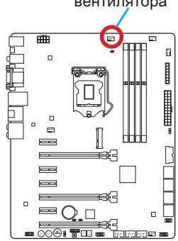
Pa3bem nodknquchna BHTnJIrTopa

- Haxmte Ha paiaatop cbexy TaK, YTO6bI 3aKePnITb YeTbIpe 3aueKn B OTBepCTnX Ha MaTePHNcKo PnATE. Haxmte Ha 3aueJIKn DnIg 3aKePnJIeHnBEHTnJIaToPA. KaKdbI n3 3aueJOK fHKCnpyeTc C xapAKTePnhIM cIeJYKom.
- Ocmotpnte MaTeepnHckyo PnAty u OnpeJeNte npabunbHocTb 3akpenJIeHna 3aKIMOB.
- И, наточ龟, полочик Кабель вентлгета поцessора К разьему вентлгета на сисимонп палte.

BhIMaHHe
- Ipeed BkIIOueHHeM CnCTeMbI pOBepbTe rePMeTNUHOCTb CoeINHeHm MExdY npouceccopOM n padNaTopoM.
- Ecnn npoueccop He yctaHOBJIe, Bcerda 3aunuauTe KOHTaKTbI npoueccopHoro coketa nlaactIKOBOK KpbIkoK.
- Ecni Bbl npnoobpenn OTeJeBHo npoceccop n npoceccorpHk Kyep, noDpo6hoe OncaHne yctaHOBKn CM. B DokymeHTaCm N daHOMy Kyepy.
Pa3bEmbl DIMM npedna3HaueHb IJy yctaHOBKn MoUyIe namrTn. PoOp6Hyu INΦopMaζH O COBmecTlMbIX KOMNoHEHTax cM. Ha caIte http://www.msi.com/ service/test-report/

BuiTeo DeMoHcTepaUa

CmOTpuTe BnDeo,yTo6bI y3HaTb KaK yCTaHOBtB nAmrTb N0 yKa3aHHOMy aDpecy.
http://youtu.be/76yLtJaKICQ
Праинla залленягнд пи Испьзовани Дыхкагьногуpeхima Dual-Channel
В дыхканьном ржиме мodyлеламгт одовременho пeredаыт b n polуат даньпюдвум калamшинbl. Влоченье дыхканьногоржимa Dual-Channel moxket noBicntb npoin3bOJNTeJIbHoctb cnCTembl. Ha pncyHKax nHXKe nokazahlpapabila 3anONHeHnI rHe3dnamgTnpinncpOB30BaHHn dByxkaHaNBHoropexkma Dual-Channele.

BhIMaHHe
- Moулл DD3 He B3aHmO3aMeHЯeMb C MoулЯMn DDR2, cTaHapr DDR3 He nOДерЖиBaet ObaTHyIO CBMeCTHMocTb. Moулл namrN DDR3 cNeJyET yCtahAbNBAbTB b pa3bEmbl DDR3 DIMM.
- Дя обесеньястаблбов paobtbi CnCTeMbI BДыхканьhom pexime yctahablnbaioTcmaулпnamrtu OndHaKOBOrTo TIna n EMKOCTN.
B CBA3N CO CNEUΦKo NcNoJIb3OBAHnI pecyPCOB MmKpOnpoCeccopa, npu yCTaHOBKe MOdyNei nAMrTn EMcKocTbIO 8 ΓB BO Bce pa3bEmbl DIMM cncTeMHa nAMrTb ONpeDJIeTc TOnbKO Do 31+ ΓB (HeNoJIbIe 32 ΓB).
Дя установки материнсков плatable на мостахно плATE сисмHorо 6лoka chача на установпгеонбхODIMьгь установочьгь стой.Еси в komплент NOCTавки сисмHorо 6лoka BXODIT 3адня панель вда-bывда,заменite ee 3адня панель вда-bывда, кOTOPЯ NOCTABЛЯETСС MATEPINHСКО Плато. 3адня панель вда-bывда 6e3 trya установльbaeTCB CSCTMHOM 6лoke komпьотера 6e3 поимения винтOB.COBmecTte yстановочьгь стой MONTAXHONПлatable C OTBepCTNIMNoID uystahoBOCHyBE BnHTbI Ha MATEPINHСКО Плateи 3akpenITE mATEPINHCKYU pIATy BVNTAMN, KOTOPbie NOCTaBLJIOCTCB MECTe C CSCTemblm 6lOKOM.Hnke nokazao paCnoLOXKeHne OTBepCTN IOd y cStahOBOCHyBE BnHTbI.DonONHInTeLbHyU INΦopMaupcNtCM.BpyKOBOCTBe KCSCTEMHomy 6lOKy.
! Bhimahaune
-ПложиTe MaTePNHcKyI pIaTy Ha poBHyI u NcIcyI NOBepXHOCTb.
Bo n36eXaHHe NOBpeXdEHH MaTePHNcKo PnAtpbI, 3akpenPte 3neKTPOHbIe KOMHOHeHTbHa yCTaHOBOUHbIX CToiKaX, n36eRa IV COpNKOCHOBeHnC CNTeMHbIM 6lOKOM.
- Поверьтей Наджноctь Креленя BCex Металл用电х KOMnoHeTOB Ha MaTePNHcKOn ПпATE ИИВуТРССТЕМнОгбLOka. He3akpenPENHbIe DeTaNMOrTy PnIBeCTN K KOKOTKOMY 3amblaKaHInO MaTePNHcKOn ПпАБI.

Buiyeo,DeMoHepaH
CMOTPTE BnDcEo,HTO6bI y3HaTb KaK yCTaHOBtbpa3bEm NITaHn.
http://youtu.be/gkDYr_83l4

JPWR1~2:Pa3bembl nHTaHnA TX
3Tn pa3bembl npedHa3hauehblIy nOdkluoyehna pa3bema nItaHNA ATX.ДЯ nOdkluoyehna ATX pa3bema nItaHNA COBmecTne Ka6JIb nItaHNA c pa3bEmOM npOchu 3akpennte erO.Ipn npabInbHom BblOnHeHHn nOdkluoyehna 3aueKka Ha ka6ene nItaHNA 3akpenlareTcB CINOBom pa3beme MaTePHNcKoI PnAbl.

BhIMaHHe
Дя obecne�еня Stabnho npabotb CnctemHno nIaTb npOBepbTe HaedxHocTb NOKNUOeHry Bcex KaBeNei NtAHN K COOTBETCTByUOeMy 6bOKy NtAHN ATX.
CLOTbI pauchepenH
BnIeO/YcTaHOBKa DnCKpeTHoN BnIeOKapTbI
IyoMOnuHaHIO,DaHHaIIaTaIcNoB3yEt rpaΦnueckoe JdoPO INTePnpoBaHHO BCPU,HO BbI TaK Je MoXeTe 3NaHTeNbHO NObICNT rpaΦnueckyo npOn3BOUInTeNbHOCTb CnCTEmbl,NyTeM Do6abJeHne ODoH NIN HeCKOJIbKINx DnCKpeTHbIX BnDEOKapT B CnOTbI paCnupeHn.ДЯлушe COBMeCTmOCTn peKOMeHdyETc IcNoJb3OBaTb rpaΦnueckne KapTbI MSl.

Buae O DeMoHepaH
CMOTNE BINO, uTObI y3HaTb KaK yCTaHOBnTB BInDeOkaPty Ha CNOTe PCIe x16 c 3amKom.
http://youtu.be/mG0GZpr9w_A

YcTaHOBka OJHO BnDEOkapTbI
- OnpeDenite TnCnTpaacunpeHn, KOTOpb nCnObl3yeTc BnDEOKapToi. HauInTe COoTBetCTBlyUOni CnOt(bI) Ha MaTePHNckO nnate. BbHbTe 3aunTHyo KpbuKy cNoTaOB) paacunpeHn i3 Kopnyca cnCTemHoro 6noka.
- PacnoIoxKeTBe VbIeOkaPty NaCnOtOM(AMN) IaIpaCunpeHnraTak, YTO6bl npOrbI NOkJIIOUeHn MOHITOpOB 6blI HAnPaBHeHbKO BHeUHei CTOpOHe CnCTeMHORO 6noka.ДЯ yCTaHOBKn OOnHb VbIeOkaPbI peKOMeHNdyETcNcNoJIb3OBA Tb CNOT PCI_E2.
- Bctabte BndeokapTy B cIOT(b) paCunpeHna. B cIpyae npaBnBHOy yCTaHOBKn KapTb, 3aueKna(n) Ha cIote(ax) paCUnpeHna DOJXHb 3aueKNHyTbcra.
- Пи Heo6xOdMocTn, npKpyTne BIndeokapTy K KopnyCy cnCTeMHoro 6NoKa BInrTom.ДЯ HeKOtOpbIX BIndeokapT Tpe6yETcnoKJIuOHeHne HEnocpeIcTBeHHO K 6NoKy NITaHry OTDeNbHbIM Ka6eHem.
- Долоннельные Истукции по установке дайевори искто只得 сецалыньх папаметров подоставлени в ркуковсковп Видаокарт.
SATA1~8:Pa3bembl SATA
Даньий pa3ьем яВЛЯETСBAICOKOCKOPCTHbIM ИНТЕРБЕСCOM SATA.КлIOБOMy pa3ьему SATA moKHO NOДКЛIOUHTb OJNO yCTpoIcTBO SATA.КуCTpoIcTbAM SATA OTHOCYrJKeCTKHe DNCKn, TBePDoTeNbHbIe HAKONITeNи HAKONITeNHa ONTNuecknx DnCKax (KOMNAKT-DnCKn/DVD-DnCKn/Blu-Ray-DnCKn).

POWER1: Khonka nHTaHnA
3Ta KhoNka npedHa3HauHeHa IaB BKIOUeHnI BbIKIOUeHnCnCTEmbl. HaxMnte Ha KhoNky OdnH pa3 IaB BKIOUeHnI JIN BbIKIOUeHn CnCTEmbl.


RESET1: Khonka nepezarpy3kn
3Ta KhoNka IpeDHa3HaueHa dIy nepe3aRpy3Kn CnCTeMbI. HaxMITE Ha Hee dIra 6bOca CnCTeMbI.

FASTB1:Khonka GO2BIOS
HnKnn nHnKaTOp mraet CnHm-Pekm 1OC Genie.
KoIbI INIINkaTOpa 3arpy3kn (Debug LED) nepeuNcIeHb I Ta6JIne HnKe.
Ta6nua KoOoB INDnKaTopa 3aRpy3Kn
Current CPU/ DRAM/ Ring Frequency
3Tn 3JIeMeHbI NOKa3bIBaHOT TEKUZne YCaTcTOTbY cTaHOBJIeHHOrO nPoueccopa, nAmrtn I uHb Ring. 3Tn 3NaHeHn HeJb3r N3MeHraTb.
CPU Base Clock (MHz) [Default]
UctahOBka 6a3OBoT TaKToB OuaCToTb II. IVImeHne 3TOrO npaMeTp a
obecneuBaet Bo3MOxHocTh «pa3roHa» LII. Obpaaaem BaWe BHMaHne Ha To,
yTO KOMnAHnI He rapaHTnpyET ycNeuHocTh BbINONHeHnPa3roHa n CtaBnJbHOCTb
CnCTeMbI. 3OT TnyHKT Np8BJIeTcR, KOrDa yCTaHOBJIeHHbI pOuceccop NoDdepXkBaet
daHHyO fYHKsIO.
Current CPU Base Clock Strap
Ioka3bIbaeT noIocy Tekyuei 6a3OBo YacTObl. 3To 3NaHeHne HnB3a N3MeHrB.
N3MeHne daHHoro NyHKta BO3MOxHO TOnbKO B Tom cnyae, ecNI pOuceccop
noIDepKbIbaeT daHHUo fYHKUIO.
Adjust CPU Base Clock Strap [Auto]
UcTaHOBka nOLOcb TEkyuue 6a3oBOu yactOTbI cII. IV3MeHeHne 3TOro napameTp aOeCneuBaet BO3MOxHocTh «pa3roHa» 6a3oBOu TaKTOBou yactOTbI cII. O6pauaem BaWe BHNMaHne Ha To, YTO KOMnAHn He rapaHTnpye TcpeuHOCTb BblONHeHHa pa3roHa u Cta6unbHOCT cb CnCTeMbI. IV3MeHeHne DaHORO nyHKTA BO3MOxHOToIbKO
В ТОМ слуаe, eclin npoцescop noДдеркиBaet daHnyю Функцию. Eclin 3начени уctановлени B "Auto", BIOS abTomatnueckn hactpoNT 3TOT napametp. [Опци: Auto, 1.00, 1.25, 1.67]
CPU Base Clock Apply Mode [Auto]
YctaHaBJIbAeT cnOCo6 npIMeHnI N3MeHnI dIy KoppeKtnpOBKn 6a3OBoi YacToBi LII.
[Auto] 3ToT npaMeTp 6ydt HacTpoeh aBtOMaTHueckn c NmOuIbBIOS.
[Next Boot] Ipoceccop nepeienet ha ckoppeKtnpOBAHHyio 6a3OByIO yactOtTy LCnocne nepe3arpy3kn.
[Immediate] Пюцeccор перидет на скорптурааную базовю чаготу LПНемедлесно.
>CPU PCIE PLL [Auto]
Bb6op pexmAPLL (Phase Lock Loop) nA CPU PCIe. 30T nyHKT noBnEeTc, KOrda yctaHOBHeHHn Ipoueccop nOdePExBaet n3MeHeHne daHHro npaMeTa.
[Auto] Napametp 6ydt Hactpoeh aBToMaTuYeCKn C nOmoIbBIOS.
[LCPLL] BknoueHne LC PLL nI HOpMaIbHorO nCNoJIb3OBAHnA.
[SBPLL] BkIquHne SB PLL nla 3KcTpMaJIbHoro pa3roHa.
Filter PLL [Auto]
BkHoueHne Hn BbKIOUeHne FnbTpPLL nI. 3TOT nyHK TnoBnEETc, KOrda yctaHOJIeHHb npOceccop noIDepxNBAe t N3MeHeHne daHHro npaMetpa.
Adjust CPU Ratio [Auto]
3aDahne MHOKInTeI npOeCCopa IyCTaHOBKn Ero TAKTOBn YAcTOTbI npOeCCopa.
IV3mEnHe N daHHoro napameTp a Bo3MOxHo TOnbKO b Tom cnyae, eCNI npOeCCOP
PIOdepKINBaet dAnHyo fHyKcNIO.
Adjusted CPU Frequency
Ioka3bBaetekyuoyuactOTyLl.3To3haueHne HeJb3n3MeHrTb.
EIST [Enabled]
BkJIOUeHne IJIY BbIKIOUeHne TexHONorIN Enhanced Intel® SpeedStep.
Intel Turbo Boost [Enabled]
BkIoueHne IIN BbIKIOueHne Intel Turbo Boost. 3TOT nyHKT noRBAeTc, KOrda yCTaHOBJIeHHb IpoUeCCOP NOdEepKJnBaET daHNy OfYHKUIO.
[Enabled] BkIIOUeHHe 3ToI ΦyHKcII N pInBODIT K aBTOMaTNUeCKOMy yBeJIuYeHIO npOn3BOIDTeNbHOCTn IpoUeCCopa.
[Disabled] ΦyHKZnBbIKHoueHa.
Enhanced Turbo [Auto]
Функця Enhanced Turbo no3BOLЯТ yBelenuBaTb чаToTy на BCexЯДрах npoцeccopa.
[Auto] ΘOTI npaMeTp 6yET HAcTpoEH ABToMaTHueCKn C NOMOuBIO BIS.
[Enabled] YBeHneHne YactOTb IBCex IpoUeCCOpHBIX Jaep Do MAKcMmaNbHorO 3HaHeHn.
[Disabled] ΦyHKnY BbIKNIOHeHa.
OC Genie Function Control [By Onboard Button]
Дявкюуняфункци OC Genie haxmITE bnpTyajbHyIO KhoNKуВBIOSипнФиЗИЧECKYO KhoNKу Ha MaTePNHcKoi ПаTe.БкючЕпe Функци OC Genie no3BOJЯET abTomatuueckn pa3roHЯТь сntTeMу C ONTUMN3InpOBaHHbIM npoФиЛem pa3roHa MSI.
[BryBIOS Options] IINBAKIOUeHnA FyHKmNOC Genie HAKMITE Ha BnPtyaIbHyIO KhoNky OC Genie B BepxHem JEBOM yrJy 3kpaHa HacTpoEk BIOS.
Adjust Ring Ratio [Auto]
UctaHOBka MHOKHTeJII ShINbI Ring.Диana3OH dOnyCTmBIX 3HaueHn 3aBcNt OT UctaHOBJIeHHoro npOceCCopa.
Adjusted Ring Frequency
Adjust GT Ratio [Auto]
YctaHOBka MHOxKInTeIa Iy INTErPnpOBaHHo rpaФnIK. DnaNa3OH DoNyCTmBIX 3HaueHn 3aBnCIT OT YcTaHOBJIeHHOr npoceccopa.
Adjusted GT Frequency
YctaHabJIbnaeT HanpIeKHe NcMeIeHnB I npOeHTax IpnVdroop npOeCCopa. Ppi yCTaHOBKe B "Auto", BIOS abTOMaTNUeCKn HAcTPONT 3OT nanopMeTp. [Onu: Auto, +12.5%, +25%, +37.5%, +50%, +62.5%, +75%, +87.5%, +100%]
CPU Over Voltage Protection [Auto]
YcTaHaBnBaet BepxHIOI rpaHNUy MaKcMmaIbHOrO HapJxHeHIN IaunTbI npoueCCopa O T CInuXOM BbICOKOHO HapJxHeH.N. Ecn yCTaHOBneHO "Auto",BIOS ABTomatUeCKn HAcTpO NT NapaMeTp. Yem BbIe 3HaueHne TEM HIXe CTenehb 3aunTbI N BblE BepoARTHOCTb BbIXOda CNCTEmbN 3CtPOr.
CPU Under Voltage Protection [Auto]
YcTaHaBnBaET HxHKnIO rpaHnUy HaPjKeHnI dJI 3aUHTbI pOuceccopa OT CInuKOM Hn3KOrO HaPjKeHnI. EcIn yCTaHOBJIeNo "Auto",BIOS abTomatueckn HAcTpONT 3TOT npaMeTp. Yem BbIe 3NaHeHne TEM HNKe CTeneHb 3aUHTbI n BBIe BEPOrTHoCTb BbIXOJa CNCTeMbI N3 CTpor.
CPU Over Current Protection [Auto]
YcTaHabnBaet orpaHueHne no MaKcImaIbHomy TKy dIra 3aUHTbI npOeccopa.
PpN yCtAHBke B "Auto", BIOS aBTOMaTnueCKn Hactpont 3OT napAmeTp. CmIuKoM
BbICOKOE 3HaueHne MoKeT pINBeCTn K NOBpeXdEHNIO CNTeMbI.
CPU Switching Frequency [Auto]
YctaHabnBaetckopocb pa60tbyPWM nIy cta6nIn3aunn HaprrKeHnraPa npouecccopa mNHHm3aun nnana3oHa nybcacun. YbeuueHne pa6ooye ckopoctn PWM npBODNT K cnblHomy harpeBy MOSFET. Ipeed tem kak yBeuHnTb 3naueHne y6eintecb, yTO oxJaXdHne dnn MOSFET yCTaHOHeo. PpynycahOBke B "Auto", BIOS abTOMatUcEckn hactponT 3OT napamTp.
CPU VRM Over Temperature Protection [Enabled]
BkIIOUaETnIN BbIKIOUaET CPU VRM nla3aunTb ot neperpeBa.
[Enabled] YctaHabnBaet BepxHee 3NaueHne TempepaTypbHa CPU VRM nna 3aunTbI OT neperpeBa.
[Disabled] ΦyHKZIy BbIKHcyeHa.
CPU Power Duty Control
Bb6op MeToa ynpabLeHn VRM dIy pa3bI nTaHn.
Current VCCIN Voltage
Покаьовп Текуший habрахени CPU VCCIN. 3To 3NaЧени HeJIb3Я ИЗМЕнТБ.
- CPU Core Voltage Mode/ CPU Ring Voltage Mode/ CPU GT Voltage Mode [Auto]
I03B0JIaTe BbI6paTb pexkma ynpabJeHnHa npJxKeHnMn.
[Auto] ΘTOT napametp 6ydt Hactpoeh ABTomatnueckn c nomooubBIOS.
[Adaptive Mode] YctaHObKa aanTnBHorO HanpJxHnA BToMaTnueckn IJI ONTmN3aUIN npOn3BOAnTeNbHOCTn CnCTeMbI.
CPU Core Voltage/ CPU Ring Voltage/ CPU GT Voltage [Auto]
UctaHOBka HaprJKeHn. Pnp yCTaHOBke B "Auto", BIOS ycTaHOBnT HaprJKeHn aBtOMaTnueckn. Bbl TAKKe MoKTe HacTpOntb HaprJKeHn BpyHyIO.
- CPU Core Voltage Offset Mode/ CPU Ring Voltage Offset Mode/ CPU GT Voltage Offset Mode/ CPU SA Voltage Offset Mode/ CPU IO Analog Voltage Offset Mode/ CPU IO Digital Voltage Offset Mode [Auto]
Bb6op pexkma hnapxeknmeu.
[Auto] Napametp 6ydt Hactpoeh aBToMaTnueckn C nOmoIbBIOS.
[+] I03B0JareT yctahOBHT noIOnKInTeJIbHoe HaprrKeHne CMeUeHn.
[-] 103B0JareT yctahOBnTB OTpuiataJIbHoe HaprrKeHne CmeueHna.
- CPU Core Voltage Offset/ CPU Ring Voltage Offset/ CPU GT Voltage Offset/ CPU SA Voltage Offset/ CPU IO Analog Voltage Offset/ CPU IO Digital Voltage Offset [Auto]
I03B0JIaTe yCTaHObITb 3HaueHHe CMeUeHn IJr 3TNx HapJxKeHn.
- Current CPU Core Voltage/ Current CPU Ring Voltage/ Current CPU GT Voltage/ Current CPU SA Voltage/ Current CPU IO Digital Voltage
Ioka3bibaet Tekyuine HaprrxKeHn. 3TO 3NaueHne HeJIb3r N3MeHrTb.
Internal VR OVP OCP Protection [Auto]
BkIouHHe IIN BbIKIOUcHHe 3aIITbI OT nepeHaPraJKeHn I nepepy3Kn PO TOKy dIy BHyTpeHHnx peryIaTOpOB HapraJKeHn pOueccopa.
[Auto] 3TOT npaMeTp 6yIeT HAcTePoE h AToMaTnueCn C nOmoUbBIOS.
[Enabled] YctahabnBaet npedeHnapjKeHnHa BHyTpEHnIX peryIaTopax HnnpjKeHnIpoceccopa dIy 3aunTbI OT npeHnapjKeHnI neperpy3kn ITOky.
[Disabled] BbIKIOUeHHe FyHKIIM.
- Internal VR Efficiency Management [Auto]
BkIIOUeHne IIN BbIKIOUeHne ynpaBJIeHnE 3ΦΦeKTHBHOCTbO BHyTpEHbIX peryIaTOPOB HapJxKeHnIpoueccopa.
[Auto] 3ToT npaMeTp 6yIeT HacTpoE h ABTOMaTHueCn NOMOuBIOS.
[Enabled] BkIIOuAeT ynpaBJIeHne 3ΦΦeKTHBHOCTbIOp peYJrTOPOB dIg KOHTpOJIa 3HEproc6epeKeHnI.
[Disabled] BbIKIIOueHHe FyHKUIM.
DRAM Voltage [Auto]
UctaHOBka HaprjKeHnnaTn. Ecn 3NaueHne yCTaHOBJeHO B "Auto",BIOS UcTaHaBnBaET HaprjKeHnHa naTn abTomatueckn. Bbl TaKke MoKeTe HaCtpoNTb erO bpyHyIO.
Current DRAM Voltage
Ioka3bIbaetekyuie HnprxKeHne namrtn.3to 3haeHne HeJIb3a N3MeHrTb.
- DDR_VREF_CA/ DDR_VREF_DQ_A/ DDR_VREF_DQ_B/ PCH 1.05 Voltage/ PCH 1.5 Voltage
UctaHbKa yka3aHHbIX hAnpJxKeHn. Ppi ycTaHOBke B "Auto", BIOS ycTaHOBt 3TN HapJxKeHn ABOMaTUnCeKn. Bbl TaKke MoKeTe HactPoNT bByHyIO.
Current PCH 1.05 Voltage
Ioka3bBaet Tekyuee HanpJxHne PCH 1.05.3To 3NaUHe HeJIb3a I3MeHrTb.
CPU Memory Changed Detect [Enabled]
BkIIOUeHne IIN BbIKIOUeHne IpeDynpKDaIOUnx COOSeHn I np3 3aRpy3Ke CnCTeMbI, KOrDa Ipoceccop IIN pAmrTb 6blN 3aMeHehbl.
[Enabled] CnCTema BbIaet npedynpeJxHne BO Bpem3arpy3Kn. Tpe6yeTc3arpy3ntb HacTpOKnIO yMOnuHaHIO dIra HOBbIX ycTpoiCTB.
[Disabled] BbIKJIouHeHne 3ToI ΦyHKn IN COxpaHHeHne TeKyuXn HacTpoE KBIOS.
Spread Spectrum
Данная Фуннкця уменишат EMI (эльготроматныеnomexи), Вьзваньд
Колебаняниим Импуньс Horo rehepatopa taktoBbIX сигнанов.
[Enabled] BkIIOUeHHe 3ToI cyHKcIMn IaI yMeHbSeHnI npo6JIembl EMI (3JIeKTPOMaHHTbIX nomex).
[Disabled] YbeJnUBaET Bo3MOxHocTn pa3roHa oChOBHO uactOTbI Ll.

BhimaHue
- Ecnn npo6bnembI c nomexamn OTCyTCTByIO, octabte 3nauehe [Disabled] (Bbykn.) Дялучewи CTa6nJIbHOcTN I npOu3BOJNTeJIbHOcTN. Ondako, ecnn Bo3HnKaIoT 3NeKtpomarHHTbIe nomexn, BKnIOUHTe napAmetp Spread Spectrum nInx yMeHbSeHnIa.
-ЧмболшемаЗанчehne Spread Spectrum, Temнжke 6dET ypoBHeb 3NeKtpomarHHTbIX NOMEX, HO cnCTema cTaHET MeHee CTabNtBHOJ.ДЯ BbIbopa nOxodjaIero 3nauchenia Spread Spectrum cBepeTecb CO 3nauchenmaуypOBHei 3NeKtpomarHHTbIX NOMEX, yctaHOBnEHHbIX 3aKOHoDaTeJIbCTBOM. - He 3a6ydbTe 3anpeTntb nCOnB3OBAHnne fynKcnn Spread Spectrum, ecnn Bbl «pa3roHJeTe» CnCTeMHUo INaTy. 3To Heo6xOJMo, TAK KaK dJaKe He6oJIbIoi dpe6e3r cInHanOB TaKTobOrO rHePaTopa MoKet npuBeCTn K OTKa3y «pa3orHaHHoro» npocecoppa.
CPU Specifications
Hajmte
CPU Technology Support
[Enable] BkIIOHTb TexHONOrnIO Intel Hyper-Threading.
[Disabled] BbIKIIOUHTe 3Ty yHKuHIO, ecII cIcTeMa He noIDepKINBaET yHKuHIO HT.
Active Processor Cores [All]
TOT nyHKT n03BONJET 3aDaTb YNCIO AKTNBbIX JApep npoceccopa.
Limit CPUID Maximum [Disabled]
BkIIOUeHne IIN BbIKIIOUeHne paCsipeHHbx 3NaueHn CPUID.
[Enabled] BIOS 6byet orpaHnUBaTb MaKcMmaIbHoe BxOHaHoe 3NaueHne CPUID nIe 6bxoJa np6bnEmbl 3arpy3kn c stapoi onepaunHOH cnCTeMbI, He noDaePKNBaIOuNe npouecCop c paunpeHHbIMN 3NaueHnA Mn CPUID.
[Disabled] IcnoIb3yIte ΦaKTnueckoe MaKcImaJIbHOe BXoJHOe 3HaueHHe CPUID.
Execute Disable Bit [Enabled]
Функцин Intel's Execute Disable Bit no3BONAE 3aunTbC8OT HeKOTopbIX BnOB 3IohAmepenHbIX DeiCTBm TnA OoN6Kn nepenolHeHn6ypeA》,pni KOTopbIX Bnpycbl nbTaIOCTCB BInOJHnTB KOd,pa3pyuHaUoHn CnCTeMy.PekomeHdyETcH He OTKnIOHaTb DaHHyOФYHKUHO.
[Enabled] NO-Execution no3B0JraT 3aUHTbC8 OT 3JIOHaMepeHHbIX DeIcTBn IN BnpyCbI.
[Disabled] BbIKHoueHne 3ToNΦyHKmN.
Intel Virtualization Tech [Enabled]
BkIIOUeHne IIN BbIKIOUeHne TexHOJOrn Intel Virtualization.
[Enabled] BkIyauaTeXHOrnIntel Virtualization n no3BOnJeT pIaTfOpMy IЯ 3aNyCka HeKoIbKx ONepaUHOHHbIX CnCTeM B He3aBVCIMbIX pa3dJIax.CnCTema MoKeT ΦyHKUHOHpOBAt b KaK HeCKoIbKO cnCTeM npaKTNUeCKn.
[Disabled] BbIKHoueHne 3ToNΦyHKmN.
Hardware Prefetcher [Enabled]
BknjueHne nIN BbIKJUoyHne annapaTHoro npedbI6OpKn (MLC Streamer prefetcher).
[Enabled] 103BONJET ABTOMaTnueckn PpeBbI6OpKn DaHbIX INHCtpyKlMn 1namrIn B K3w L2 dIy HAcTpOkn ppon3BOIDTeNbHOCTn npouecccaopa.
[Disabled] BbIKIIOueHHe annapaTHoro npedBbI6opa.
Adjacent Cache Line Prefetch [Enabled]
BkIIOueHHe IIN BbIKIOueHHe npedBbIbOpKn npoceccopa (MLC Spatial prefetcher).
[Enabled] BkIIOUeHHe cOSeDHe NpEaBbI6OpKn IINnN K3Wa dJa COKpaUeHn BpeMeHn 3aDePckKn K3u N HAcTpoKn PPOIN3BOJNTeJIbHOCTN dJa KOHKpeTHOrO INCNoJIb3OBAHn.
[Disabled] BkIIOuAeT 3aPpauBaEMyIO IINHIO K3a.
CPU AES Instructions [Enabled]
BknHne Hn BbKIOHHe NpOJIepKKn CPU AES (Advanced Encryption Standard-New Instructions). 3ToT nyHKT nOaBJIeTc8, kOrda npoueccop npOJIepKINBaET 3Tu fynKciuio.
[Enabled] BkIoueHne noDdeprKk Intel AES.
[Disabled] BbIKIoueHne noDaeppKk Intel AES.
Intel Adaptive Thermal Monitor [Enabled]
Bknouehne nnn BbIKnouehne 3ToI fynkun nn 3aunTbI npoceccopa ot neperpeba.
[Enabled] Ymehbwaet yactoty npoceccpa, korga npoeccop npebblaaet aanTnBHyTO tempepatyp.
[Disabled] BbIKIOueHHe yHKUIM.
Intel C-State [Auto]
C-state- 3TO TexHONIOgY npaBnE hny nTahmnpoecccopa, onpeJeTcA ACPI.
[Auto] Napamet6ydtnactpoeh aBtOMaTHueeCKn c nOmoIbBIOS.
[Enabled] OnpedenraretcoctoHne npocTo CnCTeMbI 3NaHTeBHO cokpaaaet 3Hepronotpe6bene Hne npoceccopom.
[Disabled] BbIKIOUeHHe FyHKlM.
C1E Support [Disabled]
BkIouHHe nII BbIKIOUeHne yHKcN C1E dIa 3hePrc6bepeKHeN B COCTOHN OCTAHOBKn. 3TOT 3IeMeHT NOBJIaTeCn pI INB KIOUeHn "Intel C-State".
[Enabled] BknoueHne cyHKnC1E nA cnKHeHn qactoTbI n HapraKeHn npocccopa dner 3heproc6epexHn B coctoHn octaHOKn.
[Disabled] ΦyHKnY BbIKIHyeHa.
Package C State limit [Auto]
[No limit] He orpaHnUbaTb C-state npouceccopa.
LakeTiny Feature [Disabled]
BkIouHne nnn BbIKIOueHne TexHONorHn Intel Lake Tiny c iRST dna SSD. 3ToT 3JIeMeHT NOBJIaETc, KOrda yCTaHOBHeHbI npOceCCop NODepKINBaET daHHyIO fHyKUIO n pni BkIOUeHn "Intel C-State".
[Enabled] Повьшени динhamческй harpykn IO ckoppektipobaHHои npoIN3BOIDTeNbHOCTN ДЯ уckopenia CKOPOCTN SSD.
[Disabled] ΦyHKπy BbIKIHyeHa.
BhimaHne: CJeIyUOuHne nyHKbI NOBBAHTc npn BkIIOueHn "Intel Turbo Boost".
Long Duration Power Limit (W) [Auto]
HactpoNTb npedeIbHyIO MOUHocTb TDP Ha dIITeJIbHbI cpoK dIra CPU B peXIme Turbo Boost.
Long Duration Maintained (s) [Auto]
HactpoNTb MaKcImaJIbHoe BpEma paOToBl pOuceccopa c OrpaHnueHneM MoUHOCTn npN Long Duration Power Limit.
Short Duration Power Limit (W) [Auto]
HactpoNTb npedeIbHyIO MOuHocTb TDP Ha KopoTKn cpoK dIy Ipoceccopa B peKIMe Turbo Boost.
CPU Current limit (A) [Auto]
YctahabnBaetekyMMAKcMaJIbHbI npedToKaBpeKIme Turbo Boost. Korda tekymTOK npebblaet yka3aHbI npeden, pOuceccop 6ydet ABtOMaTInCeCKN CHXkATb YactOTb Jdpa DnA yMeHbSeHn ToKA.
1/2/3/4-Core Ratio Limit [Auto]
3TN nyHKtI NOBJIYOTc, TOLbKO ecNI npOeCCOP NOIDepKINBaET DaHHIO fynHkUIO. 3TN 3NEmeHTb I N03BOJnOT yCTaHaBnIBaT b npOeCCOPHbIE MHOxNteIN B pa3NIuHbIX JdPax B pexKIMe turbo boost. NyHKtI DoCTyINbI, KOrda yCTaHOBLeHHbI npOeCCOP NOIDepKINBaET 3Ty fynHkUIO.
Installation/ YctaHOBka
This chapter provides demonstration diagrams about how to install your computer. Some of the installations also provide video demonstrations. Please link to the URL to watch it with the web browser on your phone or tablet. You may have even link to the URL by scanning the QR code.
The diagrams in this chapter are for reference only and may vary from the product you purchased.