USER MANUAL H77MA-G43 MSI
The material in this document is the intellectual property of MICRO-STAR INTERNATIONAL. We take every care in the preparation of this document, but no guarantee is given as to the correctness of its contents. Our products are under continual improvement and we reserve the right to make changes without notice.
Trademarks
All trademarks in this manual are properties of their respective owners.
MSI® is registered trademark of Micro-Star Int'l Co., Ltd.
NVIDIA® is registered trademark of NVIDIA Corporation.
ATI® is registered trademark of AMD Corporation.
AMD® is registered trademarks of AMD Corporation.
Intel® is registered trademarks of Intel Corporation.
Windows® is registered trademarks of Microsoft Corporation.
AMI is registered trademark of American Megatrends Inc.
Award® is a registered trademark of Phoenix Technologies Ltd.
Sound Blaster® is registered trademark of Creative Technology Ltd.
Realtek® is registered trademark of Realtek Semiconductor Corporation.
- JMicron® is registered trademark of JMicron Technology Corporation.
Netware® is registered trademark of Novell, Inc.
Lucid® is trademark of LucidLogix Technologies, Ltd.
VIA® is registered trademark of VIA Technologies, Inc.
■ ASMedia® is registered trademark of ASMedia Technology Inc.
iPad, iPhone, and iPod are trademarks of Apple Inc.
Revision History
| Revision | Revision History | Date |
| V1.0 | First release for PCB 1.X | 2012/ 02 |
| | |
Technical Support
If a problem arises with your system and no solution can be obtained from the user's manual, please contact your place of purchase or local distributor. Alternatively, please try the following help resources for further guidance.
Visit the MSI website for technical guide, BIOS updates, driver updates, and other information: http://www.msi.com/service/download
Contact our technical staff at: http://support.msi.com
Safety Instructions
Always read the safety instructions carefully.
- Keep this User's Manual for future reference.
- Keep this equipment away from humidity.
Lay this equipment on a reliable flat surface before setting it up.
- The openings on the enclosure are for air convection hence protects the equipment from overheating. DO NOT COVER THE OPENINGS.
- Make sure the voltage of the power source is at 110/220V before connecting the equipment to the power inlet.
- Place the power cord such a way that people can not step on it. Do not place anything over the power cord.
Always Unplug the Power Cord before inserting any add-on card or module.
All cautions and warnings on the equipment should be noted.
- Never pour any liquid into the opening that can cause damage or cause electrical shock.
If any of the following situations arises, get the equipment checked by service personnel:
The power cord or plug is damaged.
Liquid has penetrated into the equipment.
The equipment has been exposed to moisture.
The equipment does not work well or you can not get it work according to User's Manual.
The equipment has been dropped and damaged.
The equipment has obvious sign of breakage.
DO NOT LEAVE THIS EQUIPMENT IN AN ENVIRONMENT ABOVE 60^ (140^) IT MAY DAMAGE THE EQUIPMENT.
FCC-B Radio Frequency Interference Statement
This equipment has been tested and found to comply with the limits for a Class B digital device, pursuant to Part 15 of the FCC Rules. These limits are designed to provide reasonable protection against harmful inter

ference in a residential installation. This equipment generates, uses and can radiate radio frequency energy and, if not installed and used in accordance with the instructions, may cause harmful interference to radio communications. However, there is no guarantee that interference will not occur in a particular installation. If this equipment does cause harmful interference to radio or television reception, which can be determined by turning the equipment off and on, the user is encouraged to try to correct the interference by one or more of the measures listed below.
Reorient or relocate the receiving antenna.
- Increase the separation between the equipment and receiver.
- Connect the equipment into an outlet on a circuit different from that to which the receiver is connected.
Consult the dealer or an experienced radio/television technician for help.
Notice 1
The changes or modifications not expressly approved by the party responsible for compliance could void the user's authority to operate the equipment.
Notice 2
Shielded interface cables and A.C. power cord, if any, must be used in order to comply with the emission limits.
VOIR LA NOTICE D'INSTALLATION AVANT DE RACCORDER AU RESEAU.

Micro-Star International
MS-7756
This device complies with Part 15 of the FCC Rules. Operation is subject to the following two conditions:
1) this device may not cause harmful interference, and
2) this device must accept any interference received, including interference that may cause undesired operation.

European Union:
Batteries, battery packs, and accumulators should not be disposed of as unsorted household waste. Please use the public collection system to return, recycle, or treat them in compliance with the local regulations.

Taiwan:
For better environmental protection, waste batteries should be collected separately for recycling or special disposal.
廢電池請回收
California, USA:
The button cell battery may contain perchlorate material and requires special handling when recycled or disposed of in California.
For further information please visit:
http://www.dtsc.ca.gov/hazardouswaste/perchlorate/
CAUTION: There is a risk of explosion, if battery is incorrectly replaced.
Replace only with the same or equivalent type recommended by the manufacturer.
In compliance with chemical substances regulations, such as the EU REACH Regulation (Regulation EC No. 1907/2006 of the European Parliament and the Council), MSI provides the information of chemical substances in products at:
http://www.msi.com/html/popup/csr/evmptrtt_pcm.html
BSMI EMI 聲明
警告使用者:
WEEE (Waste Electrical and Electronic Equipment) Statement
ENGLISH
To protect the global environment and as an environmentalist, MSI must remind you that...
Under the European Union ("EU") Directive on Waste Electrical and Electronic Equipment, Directive 2002/96/EC, which takes effect on August 13, 2005, products of "electrical and electronic equipment" cannot be discarded as municipal wastes anymore, and manufacturers of covered electronic equipment
will be obligated to take back such products at the end of their useful life. MSI will comply with the product take back requirements at the end of life of MSI-branded products that are sold into the EU. You can return these products to local collection points.

DEUTSCH
Specifications. Fr-2
Guide Rapide Des Connecteurs . Fr-4
Guide rapide du panneau arriere Fr-6
Trous Taraudes de Montage. Fr-12
KpaTkoe pyKOBoCTBO no pa3beMaM Ru-4
Pa3bembl Ha 3aDnei panenu. Ru-6
OTBepTnaIpoIyctaHOBOUHbIe BnHTbl. Ru-12
3JIeKtpoNTaHne. Ru-13
Pamr. Ru-14
CNoTbI pauchepnra. Ru-16
Pa3beMbI. Ru-17
Iepembyka Ru-25
Hactpoikai BIOS Ru-26
CbeHn o nporpaMMHom oecneHnn Ru-37

English
Z77MA-G43/
Z75MA-G43/
H77MA-G43 Series
Mainboard Specifications
Processor Support
Support 3^rd Generation Intel® Core™ i7/ Core™ i5/ Core™ i3/ Pentium®/ Celeron® Processors for LGA 1155 socket (For the latest information about CPU, please visit http://www.msi.com/service/cpu-support)
Chipset
Intel® Z77/ Z75/ H77 chipset
Memory Support
4x DDR3 DIMMs support DDR3 2667(OC)/ 2400(OC)/ 2133(OC)/ 1866(OC)/ 1600/ 1333/ 1066 DRAM (Z77MA-G43/ Z75MA-G43, 32GB Max.)
4x DDR3 DIMMs support DDR3 1600/ 1333/ 1066 DRAM (H77MA-G43, 32GB Max.)
Supports Dual-Channel mode, two DIMMs per channel (*OC = OverClocking, for more information on compatible components, please visit http://www.msi.com/service/test-report)
LAN
Supports LAN 10/100/1000 Fast Ethernet by Realtek® RTL8111E
Audio
Integrated HD audio codec by Realtek® ALC892
8-channel audio with jack sensing
Supports THX
SATA
2x SATA 6Gb/s ports (SATA1~2) by Intel® Z77/ Z75/ H77
4x SATA 3Gb/s ports (SATA3~6) by Intel® Z77/ Z75/ H77
RAID
SATA1~6 support Intel® Rapid Storage Technology (AHCI/ RAID 0/1/5/10)
USB 3.0
2x USB 3.0 rear IO ports by Intel® Z77/ Z75/ H77
1x USB 3.0 onboard connector by Intel® Z77/ Z75/ H77
Multi-GPU
Supports AMD® CrossFire™ Technology
Connectors
Back panel
- 1x PS/2 keyboard port
- 1x PS/2 mouse port
- 4x USB 2.0 ports
- 2x USB 3.0 ports
- 1x LAN port
- 1x VGA port**
- 1x DVI-D port**, supporting a maximum resolution of 1920x1200
- 6x audio ports
(** This mainboard can support dual-display function by two onboard graphics output ports).
On-Board
- 3x USB 2.0 connectors
- 1x USB 3.0 connector
- 1x TPM Module connector
- 1x Serial Port connector
- 1x Parallel Port connector
- 1x Front Panel Audio connector
- 1x Chassis Intrusion connector
- 1x MultiConnect Panel connector (optinoal)
- 1x Voice Genie connector (optional)
Slots
- 1x PCIe 3.0 x16 slot, PCI_E1, it supports up to PCIe 3.0 x16 speed
- 1x PCIe 2.0 x16 slot, PCI_E4, it supports up to PCIe 2.0 x4 speed
2x PCIe 2.0 x1 slots
Micro-ATX (24.4 cm × 24.4 cm)
Mounting Screw Holes
8x mounting holes
If you need to purchase accessories and request the part numbers, you could search the product web page and find details on our web address http://www.msi.com/index.php
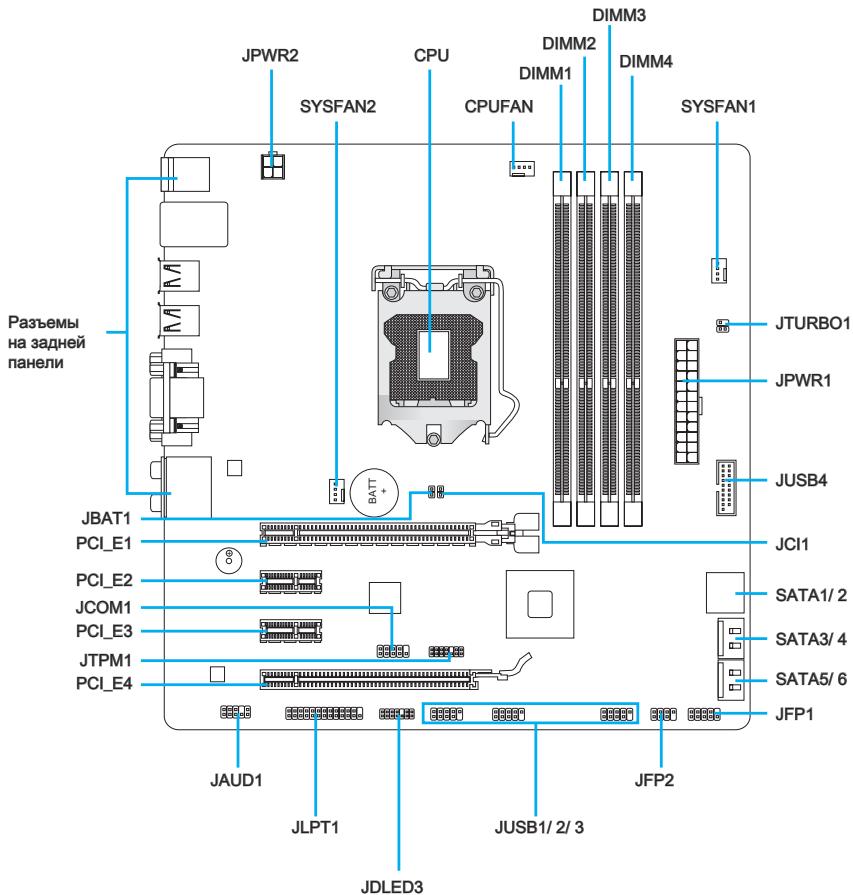
Connectors Quick Guide
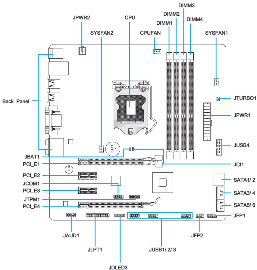
Connectors Reference Guide
| Port Name | Port Type | Page |
| Back Panel | | En-6 |
| CPU | LGA1155 CPU Socket | En-8 |
| CPUFAN,SYSFAN1~2 | Fan Power Connectors | En-18 |
| DIMM1~4 | DDR3 Memory Slots | En-14 |
| JAUD1 | Front Panel Audio Connector | En-22 |
| JBAT1 | Clear CMOS Jumper | En-25 |
| JCI1 | Chassis Intrusion Connector | En-21 |
| JCOM1 | Serial Port Connector | En-23 |
| JDLED3 | Voice Genie Connector | En-24 |
| JFP1, JFP2 | Front Panel Connectors | En-19 |
| JLPT1 | Parallel Port Connector | En-23 |
| JPWR1 | ATX 24-pin Power Connector | En-13 |
| JPWR2 | ATX 4-pin Power Connector | En-13 |
| JTPM1 | TPM Module Connector | En-22 |
| JTURBO1 | MultiConnect Panel Connector | En-24 |
| JUSB1~3 | USB 2.0 Expansion Connectors | En-21 |
| JUSB4 | USB 3.0 Expansion Connector | En-20 |
| PCI_E1~E4 | PCIe Expansion Slot | En-16 |
| SATA1~6 | SATA Connector | En-17 |
Back Panel Quick Guide
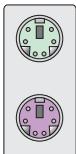
Mouse
Keyboard
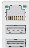
LAN
USB 2.0 Port
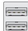
USB 2.0 Port

USB 3.0 Port
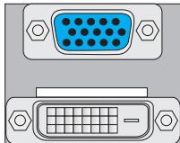
VGA Port
DVI-D Port


Line-In
Line-Out CS-Out

Mic

RS-Out
CS-Out

SS-Out
Mouse/Keyboard
The standard PS/2® mouse/keyboard DIN connector is for a PS/2® mouse/keyboard.
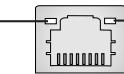
LAN
The standard RJ-45 LAN jack is for connecting to a Local Area Network (LAN).
Yellow
Fellow
Green/Orange
| LED | Color | LED State | Condition |
| Left | Yellow | Off | LAN link is not established. |
| On(Steady) | LAN link is established. |
| On(FLASHING) | The computer is communicating with another computer on the network. |
| Right | Green | Off | 10 Mbits/sec data rate |
| On | 100 Mbits/sec data rate |
| Orange | On | 1000 Mbits/sec data rate |
USB2.0Port
The USB 2.0 port is for attaching USB 2.0 devices such as keyboard, mouse, or other USB 2.0-compatible devices.
USB 3.0 Port
USB 3.0 port is backward-compatible with USB 2.0 devices. It supports data transfer rate up to 5 Gbit/s (SuperSpeed).
Important
In order to use USB 3.0 devices, you must connect to a USB 3.0 port. If a USB cable is used, it must be USB 3.0 compliant.
VGA Port
The DB15-pin female connector is provided for monitor.
DVI-D Port
The DVI-D (Digital Visual Interface-Digital) connector allows you to connect a LCD monitor. It provides a high-speed digital interconnection between the computer and its display device. To connect an LCD monitor, simply plug your monitor cable into the DVI-D connector, and make sure that the other end of the cable is properly connected to your monitor (refer to your monitor manual for more information).
Important
The VGA and DVI-D ports on the mainboard are designed to serve as IGP (Integrated Graphics Processor) used. If you installed a processor without integrated graphics chip, these display ports will have no effect.
Audio Ports
These connectors are used for audio devices. The color of the jack refers to the function of the connector.
Blue-Line in: Used for connecting external audio outputting devices.
- Green- Line out: Used as a connector for speakers or headphone.
Pink-Mic: Used as a connector for a microphone.
- Black- RS-Out: Rear surround sound line out in 4/5.1/7.1 channel mode.
Orange-CS-Out: Center/subwoofer line out in 5.1/7.1 channel mode.
Gray-SS-Out: Side surround sound line out in 7.1 channel mode.
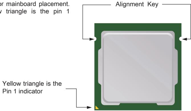
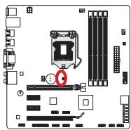
CPU: LGA1155 CPU Socket
Introduction to LGA 1155 CPU
The surface of LGA 1155 CPU has two alignment keys and a yellow triangle to assist in correctly lining up the CPU for mainboard placement. The yellow triangle is the pin 1 indicator.
Important
Overheating
Overheating will seriously damage the CPU and system. Always make sure the cooling fan can work properly to protect the CPU from overheating. Make sure that you apply an even layer of thermal paste (or thermal tape) between the CPU and the heatsink to enhance heat dissipation.
Replacing the CPU
While replacing the CPU, always turn off the system's power supply and unplug the power supply's power cord from the grounded outlet first to ensure the safety of CPU.
Overclocking
This mainboard is designed to support overclocking. Before attempting to overclock, please make sure that all other system components can tolerate overclocking. Any attempt to operate beyond product specifications is not recommend. MSI does not guarantee the damages or risks caused by inadequate operation beyond product specifications.
CPU & Cooler Installation
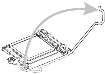
When installing a CPU, always remember to install a CPU cooler. A CPU cooler is necessary to prevent overheating and maintain system stability. Follow the steps below to ensure correct CPU and CPU cooler installation. Wrong installation can damage both the CPU and the mainboard.
- Unhook and lift the loading lever to the fully open position.
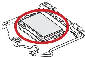
- Line up the CPU to fit the CPU socket. Be sure to hold the CPU by the base with the metal contacts facing downward. The alignment keys on the CPU will line up with the edges of the CPU socket to ensure a correct fit.
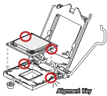
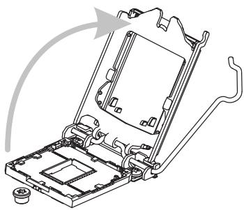
- The loading plate should automatically lift up as the loading lever is pushed to the fully open position. Do not touch any of the CPU socket pins.
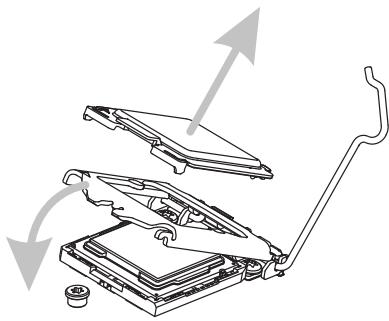
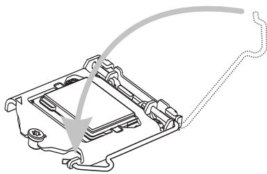
- Close the loading plate and remove the plastic protective cap.
- Inspect the CPU to check if it is properly seated in the socket. Press the loading lever down and lock it under the retention tab.
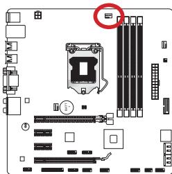
- Locate the CPU fan connector on the mainboard.
- Evenly spread a thin layer of thermal paste (or thermal tape) on the top of the CPU. This will help in heat dissipation and prevent CPU overheating.
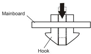
- Place the heatsink on the mainboard with the fan's wires facing towards the fan connector and the hooks matching the holes on the mainboard.
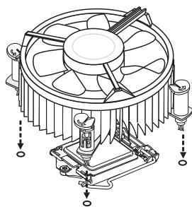
- Push down on the heatsink until the four clips get wedged into the holes on the mainboard. Press the four hooks down to fasten the cooler. As each hook locks into position a click should be heard.
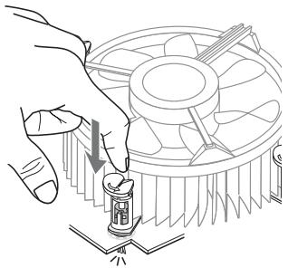
- Inspect the mainboard to ensure that the clip-ends have been properly locked in place.
- Finally, attach the CPU fan cable to the CPU fan connector on the mainboard.
Important
- Do not touch the CPU socket pins.
- Confirm that the CPU cooler has formed a tight seal with the CPU before booting your system.
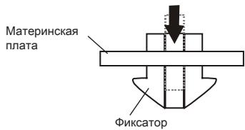
- Whenever the CPU is not installed, always protect the CPU socket pins by covering the socket with the plastic cap. (shown in Figure 1)
- Please refer to the documentation in the CPU cooler package for more details about CPU cooler installation.
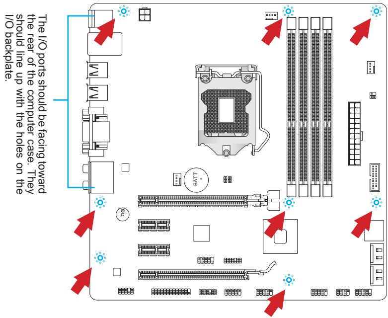
Mounting Screw Holes
When installing the mainboard, first install the necessary mounting stands required for a mainboard on the mounting plate in your computer case. If there is an I/O back plate that came with the computer case, please replace it with the I/O backplate that came with the mainboard package. The I/O backplate should snap easily into the computer case without the need for any screws. Align the mounting plate's mounting stands with the screw holes on the mainboard and secure the mainboard with the screws provided with your computer case. The locations of the screw holes on the mainboard are shown below. For more information, please refer to the manual that came with the computer case.
Important
- Install the mainboard on a flat surface free from unnecessary debris.
- To prevent damage to the mainboard, any contact between the mainboard circuitry and the computer case, except for the mounting stands, is prohibited.
- Please make sure there are no loose metal components on the mainboard or within the computer case that may cause a short circuit of the mainboard.
Power Supply
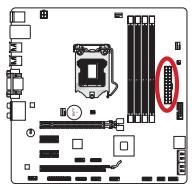
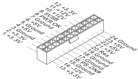
JPWR1:ATX24-pinPowerConnector
This connector allows you to connect an ATX 24-pin power supply. To connect the ATX 24-pin power supply, align the power supply cable with the connector and firmly press the cable into the connector. If done correctly, the clip on the power cable should be hooked on the mainboard's power connector.
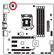
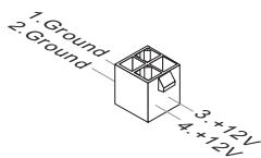
JPWR2:ATX4-pinPowerConnector
This connector is used to provide power to the CPU.
Important
Make sure that all the power cables are securely connected to a proper ATX power supply to ensure stable operation of the mainboard.
Memory
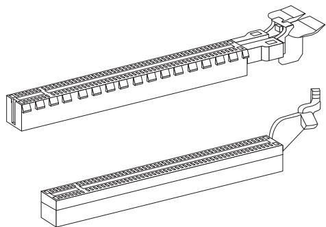
DIMM1~4: DDR3 Memory Slots
These DIMM slots are used for installing memory modules. For more information on compatible components, please visit http://www.msi.com/service/test-report
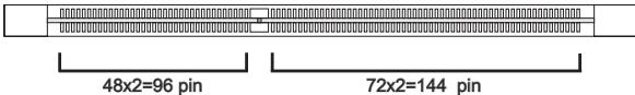
DDR3
240-pin, 1.5V
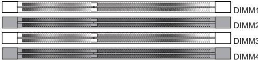
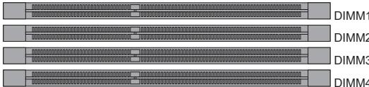
Dual-Channel mode Population Rule
In Dual-Channel mode, the memory modules can transmit and receive data with two data bus channels simultaneously. Enabling Dual-Channel mode can enhance system performance. The following illustrations explain the population rules for Dual-Channel mode.
1
2
Important
- DDR3 memory modules are not interchangeable with DDR2, and the DDR3 standard is not backward compatible. Always install DDR3 memory modules in DDR3 DIMM slots.
- To ensure system stability, memory modules must be of the same type and density.
- Due to chipset resource usage, the system will only detect up to 31+ GB of memory (not full 32 GB) when all DIMM slots have 8 GB memory modules installed.
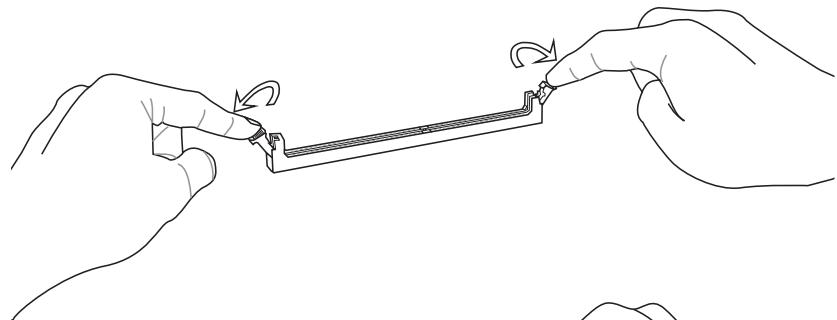
Installing Memory Modules
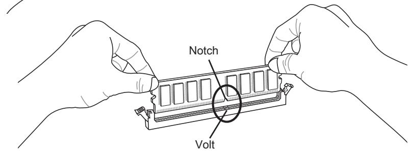
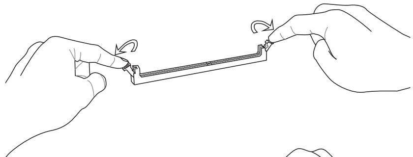
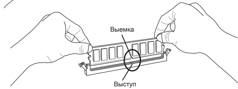
- Unlock the DIMM slot by pushing the mounting clips to the side. Vertically insert the memory module into the DIMM slot. The memory module has an off-center notch on the bottom that will only allow it to fit one way into the DIMM slot.
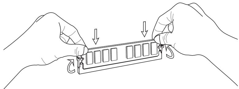
- Push the memory module deep into the DIMM slot. The plastic clips at each side of the DIMM slot will automatically close when the memory module is properly seated and an audible click should be heard.
- Manually check if the memory module has been locked in place by the DIMM slot's side clips.
Expansion Slots
This mainboard contains numerous ports for expansion cards, such as discrete graphics or audio cards.
PCI_E1~E4: PCIe Expansion Slot
The PCIe slot supports the PCIe interface expansion card.
PCIe 3.0 x16 Slot
PCIe 2.0 x16 Slot
PCIe 2.0 x1 Slot
Important
When adding or removing expansion cards, always turn off the power supply and unplug the power supply power cable from the power outlet. Read the expansion card's documentation to check for any necessary additional hardware or software changes.
Internal Connectors
SATA1~6: SATA Connector
This connector is a high-speed SATA interface port. Each connector can connect to one SATA device. SATA devices include disk drives (HDD), solid state drives (SSD), and optical drives (CD/DVD/Blu-Ray).
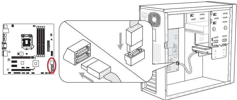
* The MB layout in this figure is for reference only.
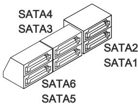
SATA1~2 (6Gb/s)
SATA3~6 (3Gb/s)
Important
- Many SATA devices also need a power cable from the power supply. Such devices include disk drives (HDD), solid state drives (SSD), and optical drives (CD / DVD / Blu-Ray). Please refer to the device's manual for further information.
- Many computer cases also require that large SATA devices, such as HDDs, SSDs, and optical drives, be screwed down into the case. Refer to the manual that came with your computer case or your SATA device for further installation instructions.
- Please do not fold the SATA cable at a 90-degree angle. Data loss may result during transmission otherwise.
- SATA cables have identical plugs on either sides of the cable. However, it is recommended that the flat connector be connected to the mainboard for space saving purposes.
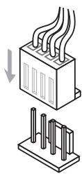
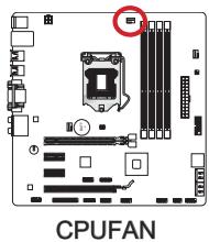
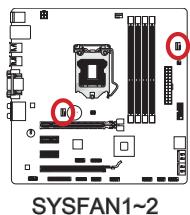
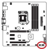
CPUFAN,SYSFAN1~2: Fan Power Connectors
The fan power connectors support system cooling fans with +12V . If the mainboard has a System Hardware Monitor chipset on-board, you must use a specially designed fan with a speed sensor to take advantage of the CPU fan control. Remember to connect all system fans. Some system fans may not connect to the mainboard and will instead connect to the power supply directly. A system fan can be plugged into any available system fan connector.
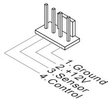
Important
- Please refer to your processor's official website or consult your vendor to find recommended CPU cooling fans.
- The CPUFAN connector supports Smart Fan Control with linear mode. The Control Center II utility can be installed to automatically control the fan speeds according to the CPU's temperature.
- If there are not enough ports on the mainboard to connect all system fans, adapters are available to connect a fan directly to a power supply.
- Before first boot up, ensure that there are no cables impeding any fan blades.
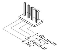
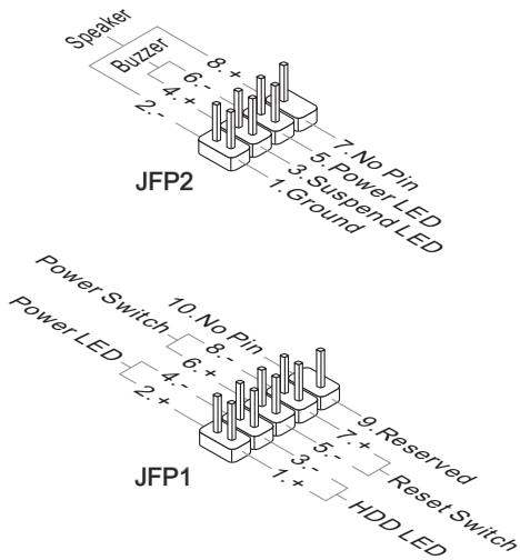
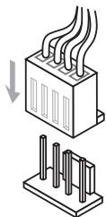
JFP1, JFP2: Front Panel Connectors
These connectors connect to the front panel switches and LEDs. The JFP1 connector is compliant with the Intel® Front Panel I/O Connectivity Design Guide. When installing the front panel connectors, please use the enclosed mConnectors to simplify installation. Plug all the wires from the computer case into the mConnectors and then plug the mConnectors into the mainboard.
Important
- On the connectors coming from the case, pins marked by small triangles are positive wires. Please use the diagrams above and the writing on the mConnectors to determine correct connector orientation and placement.
- The majority of the computer case's front panel connectors will primarily be plugged into JFP1.
JUSB4: USB 3.0 Expansion Connector
The USB 3.0 port is backwards compatible with USB 2.0 devices. It supports data transfer rates up to 5Gbits/s (SuperSpeed).

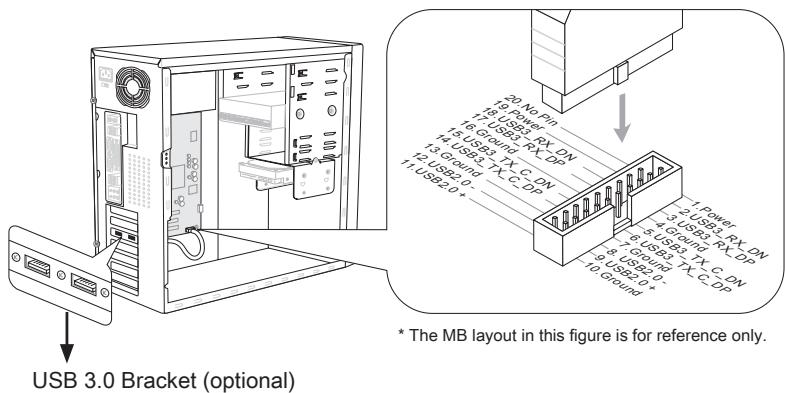
Important
- Note that the VCC and GND pins must be connected correctly to avoid possible damage.
- To use a USB 3.0 device, you must connect the device to a USB 3.0 port through an optional USB 3.0 compliant cable.
JUSB1~3: USB 2.0 Expansion Connectors
This connector is designed for connecting high-speed USB peripherals such as USB HDDs, digital cameras, MP3 players, printers, modems, and many others.
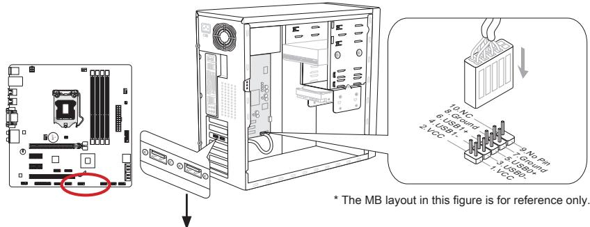
USB 2.0 Bracket (optional)
Important
Note that the VCC and GND pins must be connected correctly to avoid possible damage.
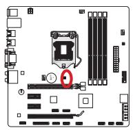
JCI1: Chassis Intrusion Connector
This connector connects to the chassis intrusion switch cable. If the computer case is opened, the chassis intrusion mechanism will be activated. The system will record this intrusion and a warning message will flash on screen. To clear the warning, you must enter the BIOS utility and clear the record.

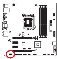
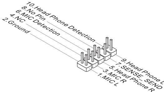
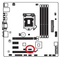
JAUD1: Front Panel Audio Connector
This connector allows you to connect the front audio panel located on your computer case. This connector is compliant with the Intel® Front Panel I/O Connectivity Design Guide.
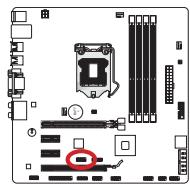
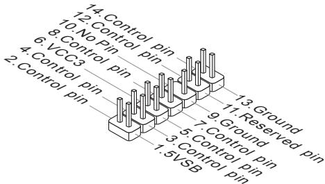
JTPM1: TPM Module Connector
This connector connects to a TPM (Trusted Platform Module, optional). Please refer to the TPM security platform manual for more details and usages.
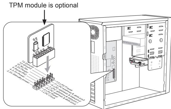
* The MB layout in this figure is for reference only.
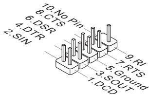
JCOM1: Serial Port Connector
This connector is a 16550A high speed communication port that sends/receives 16 bytes FIFOs. You can attach a serial device.
JLPT1: Parallel Port Connector
This connector is used to connect an optional parallel port bracket. The parallel port is a standard printer port that supports Enhanced Parallel Port (EPP) and Extended Capabilities Parallel Port (ECP) mode.

JDLED3: Voice Genie Connector (optional)
This connector is used to link to the voice control module (optional). Please refer to its user guide for more details and usages.

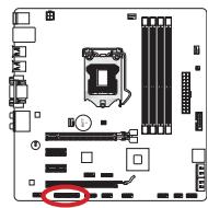
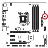
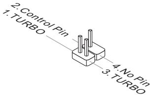
JTURBO1: MultiConnect Panel Connector (optional)
This connector is used to connect an optional front panel for controlling the OC Genie and some additional functions. Please refer to its user guide for more details and usages.

Jumper
JBAT1: Clear CMOS Jumper
There is CMOS RAM onboard that is external powered from a battery located on the mainboard to save system configuration data. With the CMOS RAM, the system can automatically boot into the operating system (OS) every time it is turned on. If you want to clear the system configuration, set the jumpers to clear the CMOS RAM.

Keep Data

Clear Data
Important
You can clear the CMOS RAM by shorting this jumper while the system is off. Afterwards, open the jumper. Do not clear the CMOS RAM while the system is on because it will damage the mainboard.
BIOS Setup
CLICK BIOS II is developed by MSI that provides a graphical user interface for setting parameters of BIOS by using the mouse and the keyboard.
With the CLICK BIOS II, users can change BIOS settings, monitor CPU temperature, select the boot device priority and view system information such as the CPU name, DRAM capacity, the OS version and the BIOS version. Users can import and export parameters data for backup or sharing with friends. After connecting to Internet, users can browse the internet, check mail and live update your system.
Entering
Power on the computer and the system will start POST (Power On Self Test) process. When the message below appears on the screen, press key to enter Setup.
If the message disappears before you respond and you still wish to enter Setup, restart the system by turning it OFF and On or pressing the RESET button. You may also restart the system by simultaneously pressing <Ctrl> , <Alt> , and <Delete> keys.
Important
The items under each BIOS category described in this chapter are under continuous update for better system performance. Therefore, the description may be slightly different from the latest BIOS and should be held for reference only.
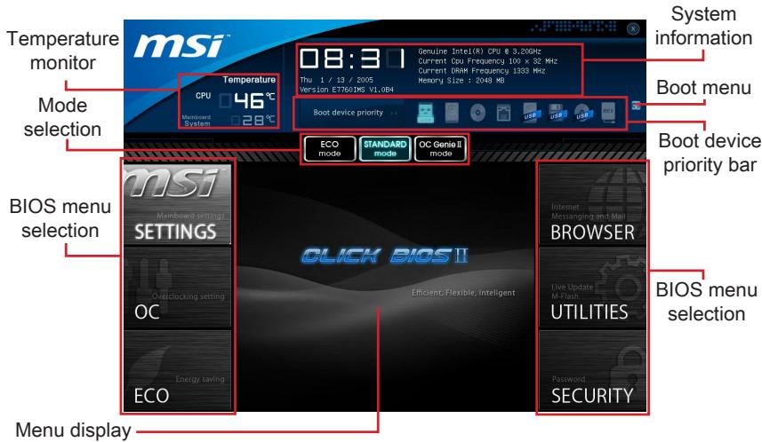
Overview
After entering Click BIOS II, the following screen is displayed.
Important
The pictures in this guide are for reference only and may vary from the product you purchased. Please refer to the actual screens of your system for detailed information.
Temperature monitor
This block shows the temperature of the processor and the mainboard.
System information
This block shows the time, date, CPU name, CPU frequency, DRAM frequency, DRAM capacity and the BIOS version.
BIOS menu selection
These blocks are used to select menus of BIOS. The following options are available:
- SETTINGS - Use this menu to specify your settings for chipset features, boot device.
- OC - This menu contains items of the frequency and voltage adjustments. Increasing the frequency can get better performance, however high frequency and heat can cause instability, we do not recommend general users to overclock.
ECO - This menu is related to energy-saving settings.
- BROWSER - This feature is used to enter the MSI Winki web browser.
- UTILITIES - This menu contains utilities for backup and update.
SECURITY - The security menu is used to keep unauthorized people from making any changes to the settings. You can use these security features to protect your system.
Boot device priority bar
You can move the device icons to change the boot priority.
Boot menu
This button is used to open a boot menu. Click the item to boot the system from the device instantly.
Mode selection
This feature allows you to load presets of energy saving or overclocking.
Menu display
This area provides BIOS setting menu that allows you to change parameters.
Boot device priority bar
This bar shows the priority of the boot devices. The light icons indicate that the devices are available.

Click and draw the icon to left or right to specify the boot priority.
An arrow symbol appears to the left of certain fields that means it contains a sub-menu. A sub-menu contains additional options for a field parameter. You can use arrow keys (↑↓) or mouse to highlight the field and press or mouse
Overclocking Profiles
CPU Specifications
MEMORY-2
CPU Features
double left click to enter the sub-menu. If you want to return to the previous menu, just press the or click the right mouse button.
General Help
CLICK BIOS II provides General Help window. You can call up the window from any BIOS menu by simply pressing <F1> or click HELP on BIOS setting screen. The Help window lists the appropriate keys to use and the possible selections for the highlighted item.
Operation
CLICK BIOS II allows you to control BIOS settings with the mouse and the keyboard. The following table lists and describes the hot keys and the mouse operations.
| Hot key | Mouse | Description |
| <↑↓→←> | Move the cursor | Select Item |
| <Enter> | Click/ Double-click the left button | Select Icon/ Field |
| <Esc> | Click the right button | Jump to the Exit menu or return to the previous from a submenu |
| <++> | | Increase the numeric value or make changes |
| <-> | Decrease the numeric value or make changes |
| <F1> | General Help |
| <F4> | CPU Specifications |
| <F5> | Enter Memory-Z |
| <F6> | Load optimized defaults |
| <F10> | Save Change and Reset |
| <F12> | Save a screenshot to a FAT/FAT32 USB drive |
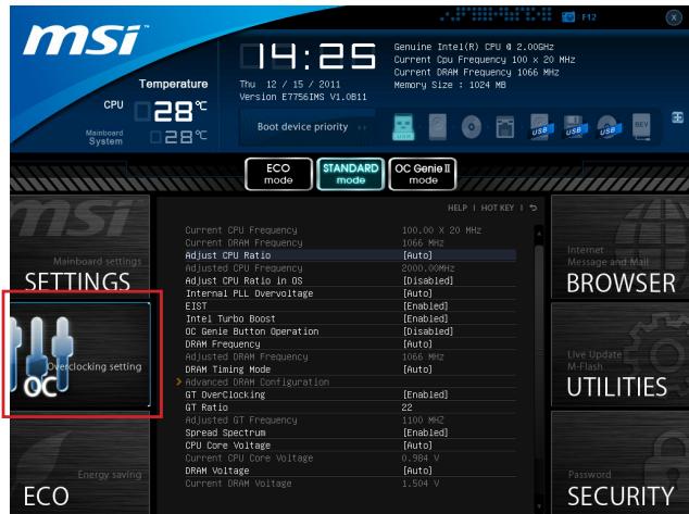
This menu is for advanced users who want to overclock the mainboard.
Important
-
Overclocking your PC manually is only recommended for advanced users.
-
Overclocking is not guaranteed, and if done improperly, can void your warranty or severely damage your hardware.
-
If you are unfamiliar with overclocking, we advise you to use OC Genie for easy overclocking.
Current CPU/ DRAM Frequency
These items show the current clocks of CPU and Memory speed. Read-only.
Adjust CPU Ratio
Controls the multiplier that is used to determine internal clock speed of the processor. This feature can only be changed if the processor supports this function.
Adjusted CPU Frequency
It shows the adjusted CPU frequency. Read-only.
Adjust CPU Ratio in OS
Enable this item to allow CPU ratio changes in the OS by using MSI Control Center II.
Internal PLL Overvoltage
This item is used to adjust the PLL voltage.
EIST
Enhanced Intel SpeedStep technology allows you to set the performance level of the microprocessor whether the computer is running on battery or AC power. This field only appears with installed CPUs that support this technology.
Intel Turbo Boost
Enables or disables Intel Turbo Boost which automatically boosts CPU performance above rated specifications (when applications requests the highest performance state of the processor).
This item allows you to enable/disable the OC Genie function.
DRAM Frequency
This item allows you to adjust the DRAM frequency. Please note the overclocking behavior is not guaranteed.
Adjusted DRAM Frequency
It shows the adjusted DRAM frequency. Read-only.
DRAM Timing Mode
Select whether DRAM timing is controlled by the SPD (Serial Presence Detect) EEPROM on the DRAM module. Setting to [Auto] enables DRAM timings and the following "Advanced DRAM Configuration" sub-menu to be determined by BIOS based on the configurations on the SPD. Selecting [Link] or [Unlink] allows users to configure the DRAM timings for each channel and the following related "Advanced DRAM Configuration" sub-menu manually.
Advanced DRAM Configuration
Press to enter the sub-menu.
Command Rate
This setting controls the DRAM command rate.
tCL
Controls CAS latency which determines the timing delay (in clock cycles) of starting a read command after receiving data.
tRCD
Determines the timing of the transition from RAS (row address strobe) to CAS (column address strobe). The less clock cycles, the faster the DRAM performance.
tRP
Controls number of cycles for RAS (row address strobe) to be allowed to pre-charge. If insufficient time is allowed for RAS to accumulate before DRAM refresh, the DRAM may fail to retain data. This item applies only when synchronous DRAM is installed in the system.
tRAS
Determines the time RAS (row address strobe) takes to read from and write to memory cell.
tRFC
This setting determines the time RFC takes to read from and write to a memory cell.
tWR
Determines minimum time interval between end of write data burst and the start of a pre-charge command. Allows sense amplifiers to restore data to cell.
tWTR
Determines minimum time interval between the end of write data burst and the start of a column-read command; allows I/O gating to overdrive sense amplifies before read command starts.
tRRD
Specifies the active-to-active delay of different banks.
tRTP
Time interval between a read and a precharge command.
tFAW
This item is used to set the tFAW (four activate window delay) timing.
tWCL
This item is used to set the tWCL (Write CAS Latency) timing.
Advanced Channel 1/2 Timing Configuration
Press to enter the sub-menu. And you can set the advanced memory timing for each channel.
GT OverClocking
This item allows you to enable/ disable the overclocking of integrated graphics.
GT Ratio
This setting controls the ratio of integrated graphics frequency to enable the integrated graphics to run at different frequency combinations.
Adjusted GT Frequency
It shows the adjusted integrated graphics frequency. Read-only.
Spread Spectrum
This function reduces the EMI (Electromagnetic Interference) generated by modulating clock generator pulses.
Important
- If you do not have any EMI problem, leave the setting at [Disabled] for optimal system stability and performance. But if you are plagued by EMI, select the value of Spread Spectrum for EMI reduction.
- The greater the Spread Spectrum value is, the greater the EMI is reduced, and the system will become less stable. For the most suitable Spread Spectrum value, please consult your local EMI regulation.
- Remember to disable Spread Spectrum if you are overclocking because even a slight jitter can introduce a temporary boost in clock speed which may just cause your overclocked processor to lock up.
CPU Core Voltage/ DRAM Voltage.
These items are used to adjust the voltages.
Current CPU Core Voltage/ Current DRAM Voltage
These items show current voltages. Read-only.
Overclocking Profiles
Press to enter the sub-menu.
Overclocking Profile 1/2/3/4/5/6
Press to enter the sub-menu.
Set Name for Overclocking Profile 1/2/3/4/5/6
Give a name by typing in this item.
Save Overclocking Profile 1/2/3/4/5/6
Save the current overclocking settings to ROM for selected profile.
Load/ Clear Overclocking Profile 1/2/3/4/5/6
Load/ Clear the stored profile settings from ROM.
Overclocking Profile Save to USB
Save the current overclocking settings to USB flash disk.
Overclocking Profile Load from USB
Load the stored settings from USB flash disk.
CPU Specifications
Press to enter the sub-menu. This sub-menu highlights all the key features of your CPU. The information will vary by model and is read-only. You can also access this information at any time by pressing [F4]. Press to enter the sub-menu.
CPU Technology Support
Press to enter the sub-menu. The sub-menu shows the installed CPU technologies. Read only.
MEMORY-Z
Press to enter the sub-menu. This sub-menu highlights all the settings and timings of your DIMMs. This information will vary by model and is read-only. You can also access this information at any time by pressing [F5]. Press to enter the sub-menu.
DIMM1~4 Memory SPD
Press to enter the sub-menu. The sub-menu displays the informations of installed memory.
CPU Features
Pressto enter the sub-menu.
Active Processor Cores
This item allows you to select the number of active processor cores.
Limit CPUID Maximum
It is designed to limit the listed speed of the processor to older operating systems.
Execute Disable Bit
Can prevent certain classes of malicious "buffer overflow" attacks where worms can try to execute code to damage your system. It is recommended you keep this enabled always.
Intel Virtualization Tech
Enhances virtualization and allows the system to act as multiple virtual systems. See Intel's official website for more information.
Intel VT-D Tech
This item is used to enable/disable the Intel VT-D technology. For further information please refer to Intel's official website.
Power Technology
This item allows you to select the Intel Dynamic Power technology mode.
C1E Support
Enable system to reduce CPU power consumption while idle. Not all processors support Enhanced Halt state (C1E).
OverSpeed Protection
Monitors current CPU draw as well as power consumption; if it exceeds a certain level, the processor automatically reduces its clock speed. For overclocking, it is recommended this feature is disabled.
Intel C-State
C-state is a power management state that detects when the system is idle and lowers power consumption accordingly.
Package C State limit
This field allows you to select a C-state mode.
> Long duration power limit (W)
This field allows you to adjust the TDP power limit for the long duration.
> Long duration maintained (s)
This field allows you to adjust the maintaining time for long duration power limit.
> Short duration power limit (W)
This field allows you to adjust the TDP power limit for the short duration.
Primary/ Secondary Plane Current value
These fields allow you to adjust over current value of CPU (primary plane)/ iGPU (secondary plane) for turbo ratio.
Primary/ Secondary plane turbo power limit (W)
These fields allow you to adjust the turbo power limit of CPU (primary plane)/ iGPU (secondary plane) for turbo boost.
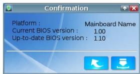
Updating the BIOS with Live Update
This section tells you how to update the BIOS by using the Live Update utility before entering Operating System. Live Update will update the BIOS automatically when connecting to the Internet. To update the BIOS with the Live Update utility:
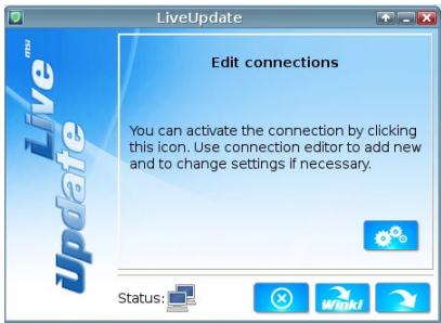
- Click Live Update button on the BIOS UTILITIES menu. (The Winki must be installed).

- Setup the connection by click the setting button if necessary.
- Click the next button
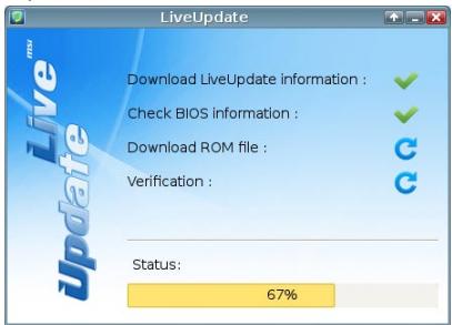
- Live Update will automatically detect the version of BIOS and download the appropriate file.
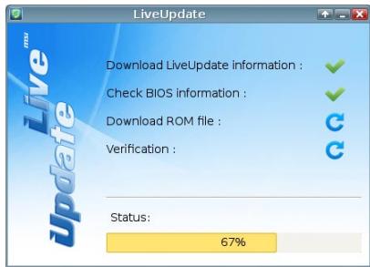
- Click the confirm button to update the BIOS.
Important
Do not update the BIOS if your system is running fine.
Take out the Driver/Utility Disc that is included in the mainboard package, and place it into the optical drive. The installation will auto-run, simply click the driver or utility and follow the pop-up screen to complete the installation. The Driver/Utility Disc contains the:
- Driver menu : It provides available drivers. Install the driver by your desire and to activate the device.
- Utility menu : It allows you to install the available software applications.
- Service base menu : Through this menu to link the MSI officially website.
- Product info menu : It shows the newly information of MSI product.
- Security menu : It provides the useful antivirus program.
Important
Please visit the MSI officially website to get the latest drivers and BIOS for better system performance.
Installing Winki
BIOS BROWSER and UTILITIES request Winki, please install the "Winki" software application from MSI Driver Disc in Windows first. And then you can access these two features by clicking their respective buttons.
To install Winki, follow the steps below:
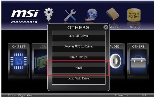
- Power on your computer and enter Windows operating system.
- Insert MSI Driver Disc into the optical drive. The setup screen will automatically appear.
- Click Driver tab.
- Click OTHERS button.
- Select Winki to start installing.
- When finished, restart your computer.

Deutsch
Z77MA-G43/
Z75MA-G43/
H77MA-G43 Serie
Spezifikationen
Prozessoren
JFP1, JFP2: Frontpanel Anschlüsse
CPU Specifications
MEMORY-Z
CPU Features
Current CPU/ DRAM Frequency
Adjusted CPU Frequency
Adjust CPU Ratio in OS
Adjusted DRAM Frequency
Advanced Channel 1/2 Timing Configuration
Adjusted GT Frequency
Current CPU Core Voltage/ Current DRAM Voltage
Overclocking Profile Load from USB
CPU Technology Support
Active Processor Cores
OverSpeed Protection
Package C State limit
> Long duration power limit (W)
> Long duration maintained (s)
> Short duration power limit (W)
Primary/ Secondary Plane Current value
Primary/ Secondary plane turbo power limit (W)
CPU Specifications
MEMORY-2
CPU Features
Adjusted CPU Frequency
Adjust CPU Ratio in OS
Adjusted DRAM Frequency
Adjusted GT Frequency
Current CPU Core Voltage/ Current DRAM Voltage
Set Name for Overclocking Profile 1/2/3/4/5/6
Overclocking Profile Save to USB
Overclocking Profile Load from USB
CPU Technology Support
Active Processor Cores
OverSpeed Protection
Package C State limit
Long duration power limit (W)
Long duration maintained (s)
Short duration power limit (W)
Primary/ Secondary Plane Current value
Primary/ Secondary plane turbo power limit (W)
Micro-ATX (24.4 cm X 24.4 cm)
OTBepCTnIy yctAHOBOHybIe BNHTbl
8xKpeNexHbIXOTBepCTnI
ПомошьВпробретенДОпOLнтельхИakceccуаровипоскeHomepaИздени
Можно hayTN no aDpecy http://www.msi.com/index.php
KpaTkoe pyKOBOdTO BO pa3bEmam
CnpaBOuHoe pyKOBoIDCTBO no pa3bEmam
YctaHOBKa CPU u BeHTnIyTopa
Pn yctahOBKe CPU y6eHntecb, yTo Ha HEm yCTaHOBJIeH BHTINJrTOp, npedOTBpaauoui nepeerpB npoceccopa. Pn yCTaHOBKe paDnaTopa/BHTINJrTOpa He 3abyte Hahectn HaCPU tepmonacty, ynyuaiouyu TeInonepedaY.
- Ocmotpnte MaTePHNckyu nIaTy nIpoBepbTeHaJeKHOCTb3aKpePJIeHnBCexΦHKcatOpOB.
11.Подключite Ka6eNB BeHTnIaTopa CPU K pa3bEmy nITaHnBeHTnIaTopa CPUHa nIaTe.
BHUMAHWE
He do paruBaTecb Do KOHTaKToB npoueccopHOro pa3bema, YTO6bI He noBpeDntb ux.
- Пелед Вкlioчени Системы обязатьно поверпту Наджно установки вентлилтора охлaxдени поцecoppa.
B cnyuae ecn npoeccop He yctaHOBeH, He 3abYbTe 3akpbIt npoecopHybI pa3bem 3aUHTHO KnpbiKo. 3To nOMOKeT n36EkaTb nobpejdeHna KOHTAKTOB. (noka3aHO Ha pnc.1)
- Плдробhoe описане установский сиземы oxлaxденя поцeccopa CM. В дOKум entaши КданHomу BeHTnIЯTopy.
OTBepCTNIOyUcTaHOBOUHbIe BnHTbl
Пи установке Материнскои плatable сачала установITE Heo6хODIMье ДЯМатеринскои плatable HOЖКИ HA WACCN B CNTeMHOM 6LOKE. EcIN K CNTeMHOMY 6LOKYPnIparaTeC3aDняпанел NGTOB VBOA/BbIODA,ЗamEнITE ee NaHEnIbO, BXOДшЕВ KOMПЛКТ MaTEPINCHSKOII pIaIb. 3Ta NaHEnIb NERKO pa3MeUaETcB CNTeMHOM6LOKe I He Tpe6byfФИKcauIN BnHTAMN.COBmecTITe HOXKN WACCN C OTBepCTnMIDANFor BnHTOB Ha MATePINCHKoi PIIATE I ZakpeNiTE MATEPINCHKyIO PIIATy BnHTAMN, PnIparaOnuZIMNCI K CNTeMHOMY 6LOKy.PacnoJoxKeHne OTBepCTn NOd KpenExhIbe BnHTBI Ha MATePINCHKOII pIate NOKa3aHO HnKe.ДОпONHInTeNbIbIe CBedeHnIcM.BpyKOBODCTBE K CNTeMHOMY 6LOKY.
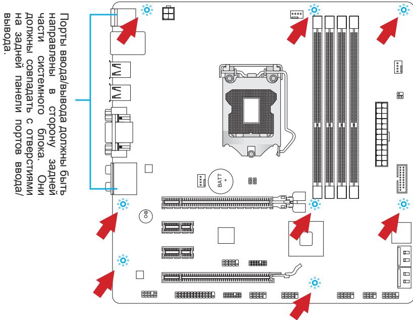
BHMMAHNE
- YctahOBky MaTePNHcKoI nIaTbI CneJeT BblIOJIHrTa H a poBHOJ NOBepxHOCTN, OUYIeHHOHT MyCopa.
Bo n36eXaHHe NOBpeXeDHeMaTePnHcKo PnIaTbI, ee 3eKeTpUeCKa CXema He DoJIxHa cOpNkacatbCra CnCTeMHbIM 6JLOKOM. 3To DocTuRaETcC NOMOuHO HOKe JnA YCTaHOBKn.
- Поверьтей Наджноctь Зakреленя BCex Металлчеснх DeТаел Ha MaTePNHcKо ПпATE N BHTPn CNTeMHOrO 6Loka.В npOTuBHom cIyuae Mocket BO3HKNHyTb KOPOTKe 3aMbIkaHne N NOBpeJdeHne MaTePNHcKо ППАТБ.
3JIeKTpOnnTaHne
JPWR1: 24-KoHTaKTbIpa3bEm nITaHnA TX
3TOT pa3bem P03BONJAE TPOKJIIOUHTb 24-KoHTaKTbHb pa3bem NITAHN ATX. Ipeed P0kIIOUHEHEM NCTOCHNka NITAHN y6eINTEcB, YTO ERO KOHTaKTbI n pa3bem Ha NIIATE npabInbHO copneHTnPOBaHb. 3aTEM NIOTHO BCTaBBte erO B pa3bem HA CNTEmHO pIate. PpnpabInbHOM BbINONHeHm CoEINHeHn, fIKCaTOP HcNIOBOM Ka6ene DoJHKEN 3AKPeINb Ka6ebb B pa3bem MaTePHNCKOH PnAtbl.


JPWR2: 4-KoHTaKThbI pa3bEm nTahnA ATX
Pazbema nitaHnna npouceccopa.

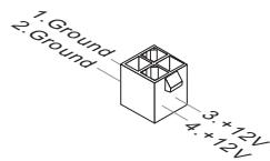
BhimaHne
Дя obecneuehenia CTabnIbHoi pa6Obl MaTePnHcKoi PnAbl npOBepbTe HaJeXHoCTb NOKnIOUeHnBex CnIOBbIX Ka6eNei K COOTBeTCTByIoUeMy 6NOKy NtTaHnA ATX.
NamrTa
DIMM1~4: CnotbI namrTn DDR3
CJIOJI DIMM Icnoj3yOTc dIy UcTaHOBKn MoDyIe namrTn. IOpO6HyOnHOpMaIIO O COBmecTUMbIX KOMIOHeHTax CM. Ha CaITe
http://www.msi.com/service/test-report
DDR3
240-KOHtAKTOB, 1.5V

48x2=96 KOHTAKTOB
72x2=144 KOHTaKaTa
IpaBnla yctaHOBKn MoUyIe NpAMrTn IJra paBoTbI B DByXkHaJIbHOM peKIMe
B dBvXkaHbHom pexIme moUyn namTn MoryT oHOBpeMeHHo nepeDaBaT bONyuATb daHbIe NO dBYm kaHaIam uHbI. Ppi nCNoIb3ObaHm N dBvXkaHaNbHoropexIma noBbIaAetc npOn3BOUnTehNoCTb cnCTembl. Hnke npBVeHbI npabIna3anJIoHeHn cNOTOB naTn dJa pa60Tb I dBvXkaHaNbHOM pexIme.

1


2


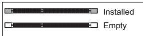
YctaHOBneHo

Tne3do nyctoe
BHMMAHNE
- Moулл памгт NDR3 He b3aunMo3aMeHЯeMbIC moулл mN DDR2; ctaHapr DDR3
He noДержИBaet obpaTHyO coBmecTImocTb. Bcerda yctaHaBnBaIte moулл
pamgTT DDR3 Br rHe3da DDR3 DIMM.
-Дя obecneueHnca6bHno pa6ToBc CNTeMbI DCJXHbI NCIOJIb3OBaTbCMyDyNITaHnOdHOro Tnna N OOnHakOBo EMKoCTN.
Bvny orpaHneHn ynceta, KOra B KaKdom pa3beme yctahOBnE 8Γ6 moydynb, MakcmaNbHO onpeDnEmeo KOJInueeCTBO namrTn COCTABnE r HenoIhIbe 32Γ6.
YCTaHOBka MOyJeI pAmrTn
- Pa36noknyTe DIMM cnot, pa3BeJa 3axmbl B cToPOhbl. BcTaBbTe moyIb namrIn B cnot DIMM BeptnKaJIbHO. Ha moUyIe namrIn NMeETcmeJeHHaOT ueHTpa BbIeMka BnH3y, 6laOJapra KToPoi ero MoKHO BCTaBtB B rHe3do DIMM TOnbKO onpeJeHbIM o6pa3OM.
- BCTaBbTe MoyIb NaMHTn B Cnot DIMM Do ynpaNtBuHOyctaHOBKe MoyI, PJIaCTIKOBBe 3bIXMbIC o6oX CTOpOH OT CNOTa, ABtOMaTnueckn 3akpoTcC XapakTePbHIM UeJIYKOM.
- BpyuHy u6eDntecb, yTo moDyIb 3aKpeIJIeB CnOte DIMM 3aUeIeKo co cTOpOHbI 3axIMa.

CLOTbIpacuHpeHnA
JTURBO1: Pa3bem MultiConnect Panel (onuohalho)
3TOT pa3bem nCnOlb3yETc dIg NIOKJIIOUeHn K OIcNHOaJIbHOJ nepeDHe nAHeJI dIynpabNeHn OC Genie n HeKOToPbIMn DOnONHITeJIbHbIMn FyHKUaMn. 3a 6oBee npOboHn INΦopMaun e HnHa3NaeHnMaN oBaPaaTeCb K pykoBOdCTBy nOlb3OBaTeJIa.
Pepembyka
CPU Specifications
MEMORY-Z
CPU Features
(↑↓) niiMbiBДЯ BbIbOpa, a 3aTeHnKmnte nii DbaXdbI ueKNHTeJIeByIO KhoNky MblSi, YTO6bI Bbl3BaTb NODMeHO. YTO6bI BepHyTbCBA RflaBHOe MeHO, npocTo haxmnte nii UeKnHte npabOi KhoNkoMblSi.
OmbaCnpabka
B pexime CLICK BIOS II nmeetcBa 03MOxHocTb NolueHnnaOp6hOn cnpaKn. Ee MoXHO BvI3BaTb N3 NIObOro MeHIO npocTbIM HaxaTneM INN HaxaTneM HELP Ha 3KpaHe BIOS setting. B OkHe cnpaKn 6ydyT nepeuNCHeBc Bce 03MOxHbE hAcToPouKn B BVb6paHHom nyHKTe MeHIO.
IcnoB3OBAHne
CLICK BIOS II no3B0nraet ynpabnTb hactpoiKaMn BIOS c nomoouMbIuN i KnaBnAtypbl. B HnKecneJeUoSe Tabniue nepeuucnEnbI uOncaHbI cyHKUOHaNbHbIe KNaBnUn N DeiCTBnC nOMoUbIO MbIuN.
Current CPU/ DRAM Frequency
Adjusted CPU Frequency
3TOT nyHKT noka3bIbaeT KekuIyU qactOty CPU. TOnbKO dnyTeHnA.
Adjust CPU Ratio in OS
BkIuHene 3ToI yHKcIN nO3BOJNT ynpaBJIb MHOxKITeIeM YacTOb CPU n3 noD OS,ncnObl3yraYtInlityMSIControl Center II.
Internal PLL Overvoltage
Даннbi npametnp nCnoB3yETc dIЯperynipOBkn HnprjxehnaФAPU (PLL).
EIST
TexHONorra Enhanced Intel SpeedStep no3B0JeaT yCTaHObntb ypoBeHb npOn3BOUInTeNbHocTn npOeCCopa pnp 3neKTPoNtAHm OT 6aTapeu INIOT cETn. DaHHe nOle npAIBJeTcra TObko B cnlyae ycTaHObKn CPU, nOdEepKINBaHOJero 3Ty texHONorHIO.
Intel Turbo Boost
3TOT nyHKT nCnOJIb3yETcA IaB BkIIOUeHn/ BbIKIOUeHn TEXHOJOrn Intel Turbo Boost. Oh nobblaet cactoty npoecccopa, korga npNKlaHbe nporpamMbI Tpe6yHT 60lbwe npoIN3BOdntelbHocTN, n TDP npoecccopa 3TO nO3BOJnEET.
TOT nyHKT nCnoJIb3yETc dIy BkJIIOUeHn/ BbIKJIIOUeHn OyHKuN OC Genie.
DRAM Frequency
3TOT nyHKT nCnONb3yeTcДЯн HAcTpoKn YacToTb DRAM. PIn BbIbOpe 3NaueHnra [Auto (ABTO)] CnCTema onPeJeJIeT 6bICTpOeIcTBne DRAM aBtOMaTnueckn. O6paTnTe BnIMaHHe Na To, YTO yCneUHOCTb pa3rOHa He rapaHTnpyETcJ.
Adjusted DRAM Frequency
3TOT nyHKT noka3bIbaeTe kTuSyU qaTo TY DRAM. TOnIbKO dIy UTeHnA.
DRAM Timing Mode
OnpeJeIeT 6yUr IIN TaMmHr DRAM KOHTpOIpOBoTaBc DaHbIMn n3 SPD (Serial Presence Detect) EEPROM ha moDyIe DRAM. PIn BbIbOpE 3NaueHnra [Auto] TaMmHr DRAM, BkIIOuA pyKtBi MeHIO, nepeuNcIeHHbIe HNKe, ycTaHaBJIbAOTcB BIOS B COOTBeCTBm C daHbIMn n3 SPD. YcTaHOBaK3NaueHnB a [Link] uIN [Unlink] no3BOJrE TByuHyIO perYIpOBoTa TaMmHr DRAM DoCTynbIe B 3Tom MeHIO n nepExoDITb B noDMHeIO «Advanced DRAM Configuration» («PacunpeHHa KOnΦnIrpyaZn DRAM»).
Advanced DRAM Configuration
HaxmTeДЯ BXOda B IOdMeHIO.
Command Rate
Advanced Channel 1/2 Timing Configuration
Adjusted GT Frequency
3TOT nyHKT noka3bIbaet Tekyu yocactOTy BCTpoEHORO rpaHueckoro JaPa. TOnbko dIyTeHn.
Spread Spectrum
Current CPU Core Voltage/ Current DRAM Voltage
3Tn nyKtbI noka3bIbaIOT tekyuee HaprJKeHne.ToIbKO dnyTeHnA.
Overclocking Profiles
HaxmnteДЯ BXOda B NOdmEnIO.
Overclocking Profile 1/2/3/4/5/6
HaxmnteДЯ BXOa B noDmeHIO.
Set Name for Overclocking Profile 1/2/3/4/5/6
YkaKInTe NmB 3TOM nOJIe.
Save Overclocking Profile 1/2/3/4/5/6
CoxpanHe TeKyuIe HactpOikn pa3roHa dIy BbIbpaHNo npoPnla Ha I3Y.
Load/ Clear Overclocking Profile 1/2/3/4/5/6
Coxpanen/yaIaJIeHne HAcTpoek npOoJnpa3roHa ha I3Y.
Overclocking Profile Save to USB
CoxpanenHe TekyuHx HacTpoek pa3roHa Ha HakoNtTeB USB.
Overclocking Profile Load from USB
3arpyka coxpaenHHbIX hAcTpoek c hakonnteJRA USB.
CPU Specifications
CPU Technology Support
Haxmte ДЯ BXOa B NOmEnIO. B DAHOM NOmEnIO OTo6paKaIOTcФyHKU,ycTaHOBNeHbE B npoceCope.ToIbKOДЯчEHNIA.
MEMORY-Z
Active Processor Cores
3TOT nyHKT n03BONJET 3aDaTb YNCIO AKTNBbIX JApep npOceccopa.
> Limit CPUID Maximum
Intel Virtualization Tech
YnyuetaeBnptyaJIN3aIIO N IO3BOJrE TcCTEme DeiCTBOBaTb B KaueCTBe HECKOJIbKINX BnPtyaJIbHbIX CNTem. IOnONHITeJIbHbIe CBeDeHnC M. Ha OΦnuaJIbHom Be6-caTe Intel.
Intel VT-D Tech
3TOT nyHKT nCnOJIb3yETcra DnA BkIIOUeHnB/BykIIIOUeHnTexHOJOrn Intel VT-D. DonONHHTeJIbHbIe CBeDeHn CM. Ha OΦuIaJIbHOM Be6-caITe Intel.
Power Technology
OverSpeed Protection
OcIeKnBaet ToK, nTope6JembI LII, n 3HepronoTpe6JeHne; ecn OHO npBeBlaaet OnpeDeneHHb yPoBeHb, pOuceccop aTOMaTuYeCKn yMeHbShaet TaKToByu YacToTy. Ppi pa3roHe 3Tu fYHKUIO peKOMeHNyETc OTKIQUHTb.
Intel C-State
C-state - coctoHne ynpaBHeHn3HeprOOnTepeBHeHnEm, OnpEeJIIOUeep npocToN cnCTembl N pONHXaIooee 3HeprOOnTepeBHeHn COOTBeTCTByIOUm 06pa3OM.
Package C State limit
Даннbi napaMeTp no3BoJЯe T bIbpaTb peXIM C-state.
Long duration power limit (W)
Даннь памету NGONь3уETс ДЯ установкиnpedelbHоМоцно TDPдпдinteHLHо pa6OТbl.
Long duration maintained (s)
Short duration power limit (W)
B daHnomone yctaHabnBaetc npedeIbHaMoIHoCTb TDP npKpaTKOBpeMeHHo pa6ote.
Primary/ Secondary Plane Current value
Primary/ Secondary plane turbo power limit (W)
Данные пол noэваягет рergyлароваь орагиченихеTurbo power npoцeccopa (ochobnoropeximam)/iGPU(Btopuhroropeximama)дяturbo boost.
06HOBJIeHneBIOSc nOmoUb Live Update
B daHmopa3dene paccka3bIbaeTcra oTom, kakobOBnTB BIOS c nOMOu bIO npniloxeHnna Live Update, nepeB BXoDM B onepaunOHnyCnCTemy. PnpoKluoyenK IVHTepHety Live Update aBtOMaTHueckn obHOBJIaET BIOS.ДЯ obHOBJIeHnBIOS c nOMOu bIO npniloxeHnna Live Update cneDuYte cneDuOuIm yka3aHnma:
- HαχmιTe Na Kθικγ Live Update LIVe B Mεην BiOS UTILITIES (CJIYXΕBHBIE ΠΙΟΓΡΑΜMbI BIOS). (Tpebyetc npεdВapntelhna yctaHOBka Winki).
- YctaHOBITE pOdkIIOUeHne, npn Heo6xOIMOCtN HaxKaB Ha KHOJky HacTPOiKN
- HακMιTe Na KhoNkUy “Далée”
- Live Update abTomatneckn obnapyknBaet Bepcno BIOS n 3arpykaet COOTBECTBvOUsn foaiJ.
- Haxmnte Ha KhoNkY npOttBepXdEHHa DnIy o6HOBneHHa BIOS.

BhimhaHne
He obHOBJIte BIOS, ecnn cncTeMa pa6oTaet HOpMaIbHO.
CBeHeHry O npOrpaMMHom o6ecneueHn
YctaHOBnTE B npINbOD ONTNUeCKNX DnCKOB pnpNraEmbly K CnCTeMHOn PJIate KOMnAKT DnCK «Driver/Utility». YcTaHOBka 3aIyCTNTC T ATOMaTNUeCKN. Bbl6epnte dpaBep INIc LyKe6hUO npOrpAMMy n CLeDyIte NHCtpyKzIyM n 3kPaH e IJn 3aBepeHn yCTaHOBKn. CodepKzHMoe Disc-DnSCa C dpaBepAMn i CnyKe6hblm npOrpAMMaMn:
- Driver menu (Mehio npaiBepo): Ha hem codepkaTcdoctynhIe dpaiBepbl. Ia nCnoJIb3OBAHnry yCTpoiCTBa yCTaHOBnte HxKbI dpaiBep.
- Utility Menu (Служебные поррамь): ДИСК ПОЗBOЛЯТ YCTАНБИТУМЕЮДЕССЕН И МЕРКПадhoe поррамнhoe обесенье.
-Service base menu (CepBnchIbe nporpaMMbl): C nOmoIbD aHaHOrO MeHOMOKHO BbInTu Ha oOpuNaIbHbI Be6-caT KOMpHaHm MSI.
- Product info menu (Инфомаши о рожукт): Oтообрахая с постения Инфомаши по рожукту komпанни MSI.
- Security Menu (Мени Беонасов): CodepknT nole3HyO aHTNBpyChyI nporpaMMy.
BhimhaHue