USER MANUAL G41M-P33 COMBO MSI
FCC-B RADIO FREQUENCY INTERFERENCE STATEMENT
This equipment has been tested and found to comply with the limits for a class B digital device, pursuant to part 15 of the FCC rules. These limits are designed
to provide reasonable protection against harmful interference in a residential installation. This equipment generates, uses and can


N1996
radiate radio frequency energy and, if not installed and used in accordance with the instruction manual, may cause harmful interference to radio communications. However, there is no guarantee that interference will occur in a particular installation. If this equipment does cause harmful interference to radio or television reception, which can be determined by turning the equipment off and on, the user is encouraged to try to correct the interference by one or more of the measures listed below.
Reorient or relocate the receiving antenna.
Increase the separation between the equipment and receiver.
- Connect the equipment into an outlet on a circuit different from that to which the receiver is connected.
- Consult the dealer or an experienced radio/television technician for help.
Notice 1
The changes or modifications not expressly approved by the party responsible for compliance could void the user's authority to operate the equipment.
Notice 2
Shielded interface cables and AC power cord, if any, must be used in order to comply with the emission limits.
VOIR LA NOTICE D'INSTALLATION AVANT DE RACCORDER AU RESEAU.

Micro-Star International
MS-7592
This device complies with Part 15 of the FCC Rules. Operation is subject to the following two conditions:
1) this device may not cause harmful interference, and
2) this device must accept any interference received, including interference that may cause undesired operation.
PART NUMBER
G52-75921XM
COPYRIGHT NOTICE
The material in this document is the intellectual property of MICRO-STAR INTERNATIONAL. We take every care in the preparation of this document, but no guarantee is given as to the correctness of its contents. Our products are under continual improvement and we reserve the right to make changes without notice.
TRADEMARKS
All trademarks are the properties of their respective owners.
MSI is registered trademark of Micro-Star Int'l Co., Ltd.
NVIDIA® is registered trademark of NVIDIA Corporation.
ATI® is registered trademark of ATI Technologies, Inc.
AMD is registered trademarks of AMD Corporation.
Intel is registered trademarks of Intel Corporation.
Windows® is registered trademarks of Microsoft Corporation.
AMI is registered trademark of Advanced Micro Devices, Inc.
Award® is a registered trademark of Phoenix Technologies Ltd.
Sound Blaster® is registered trademark of Creative Technology Ltd.
Realtek® is registered trademark of Realtek Semiconductor Corporation.
■ JMicron® is registered trademark of JMicron Technology Corporation.
Netware is a registered trademark of Novell, Inc.
REVISION HISTORY
| Revision | Revision History | Date |
| V7.0 | For PCB 7.x | January 2011 |
SAFETY INSTRUCTIONS
Always read the safety instructions carefully.
- Keep this User Manual for future reference.
- Keep this equipment away from humidity.
Lay this equipment on a reliable flat surface before setting it up.
- The openings on the enclosure are for air convection hence protects the equipment from overheating. Do not cover the openings.
- Make sure the voltage of the power source and adjust properly 110/220V before connecting the equipment to the power inlet.
- Place the power cord such a way that people can not step on it. Do not place anything over the power cord.
Always Unplug the Power Cord before inserting any add-on card or module.
All cautions and warnings on the equipment should be noted.
- Never pour any liquid into the opening that could damage or cause electrical shock.
If any of the following situations arises, get the equipment checked by service personnel:
The power cord or plug is damaged.
Liquid has penetrated into the equipment.
The equipment has been exposed to moisture.
The equipment does not work well or you can not get it work according to User Manual.
The equipment has dropped and damaged.
The equipment has obvious sign of breakage.
- Do not leave this equipment in an environment unconditioned, storage temperature above 60^ (140^) , it may damage the equipment.
CAUTION
Danger of explosion if battery is incorrectly replaced. Replace only with the same or equivalent type recommended by the manufacturer.
警告使用者
For better environmental protection, waste batteries should be collected separately for recycling or special disposal.
ENGLISH
To protect the global environment and as an environmentalist, MSI must remind you that...
Under the European Union ("EU") Directive on Waste Electrical and Electronic Equipment, Directive 2002/96/EC, which takes effect on August 13, 2005, products of "electrical and electronic equipment"

cannot be discarded as municipal waste anymore and manufacturers of covered electronic equipment will be obligated to take back such products at the end of their useful life. MSI will comply with the product take back requirements at the end of life of MSI-branded products that are sold into the EU. You can return these products to local collection points.
DEUTSCH
Thank you for choosing the G41M-P33 Combo/ G41M-P43 Combo (MS-7592 v7.x) Micro-ATX mainboard. The G41M-P33 Combo/ G41M-P43 Combo is based on Intel® G41 & ICH7 chipset for optimal system efficiency. Designed to fit the advanced Intel® Core™2 Quad/ Core™2 Duo/ Pentium® Dual-Core/ Celeron® processor in LGA775 package, the G41M-P33 Combo/ G41M-P43 Combo delivers a high performance and professional desktop platform solution.
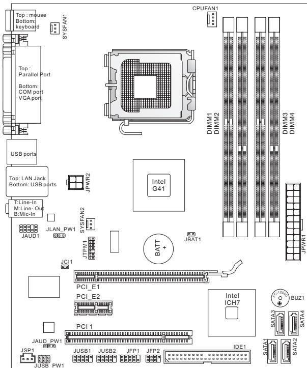
Layout
SPECIFICATIONS
Processor
Intel® Core™2 Quad/Core™2 Duo/Pentium® Dual-Core/ Celeron® processor in LGA775 package
Support 4-pin CPU fan pinheader with fan speed control (For the latest information about CPU, please visit http://www.msi.com/index.php?func=cpuform2)
Supported FSB
Up to 1333 MHz
Chipset
North Bridge: Intel® G41 chipset
South Bridge: Intel® ICH7 chipset
Memory
2 DDR2 667/800/1066(OC) DIMM slots (8GB Max)
- 2 DDR3 800/1066/1333(OC) DIMM slots (8GB Max)
- (For more information on compatible components, please visit http://www.msi.com/index.php?func=testreport)
LAN
Supports LAN 10/100/1000 Fast Ethernet by Realtek® 8111E (G41M-P43 Combo)
Supports LAN 10/100 Fast Ethernet by Realtek® 8105E (G41M-P33 Combo)
Audio
Chip integrated by Realtek® ALC662
Supports 5.1 channels audio out
Compliant with Azalia 1.0 Spec
IDE
1 IDE port by Intel® ICH7
Supports Ultra DMA 66/100, PIO & Bus Master operation mode
SATA
4 SATA 3Gb/s ports by Intel® ICH7
Connectors
Back Panel I/O
- 1 PS/2 mouse port
- 1 PS/2 keyboard port
-1 parallel port
- 1 serial port
- 1 VGA port
- 4 USB 2.0 ports
- 1 LAN jack
- 3 flexible audio jacks
Onboard Connectors
- 2 USB 2.0 connectors
- 1 S/PDIF-Out connector
- 1 front audio connector
- 1 chassis Intrusion connector
- 1 TPM connector
Slots
1 PCIE x16 slot
1 PCIE x1 slot
1 PCI slot, supports 3.3V/ 5V PCI bus Interface
Micro-ATX (19.8 cm x 24.4 cm)
Mounting
6 mounting holes
If you need to purchase accessories and request the part numbers, you could search the product web page and find details on our web address below http://www.msi.com/index.php
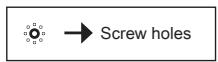
SCREW HOLES
When you install the mainboard, you have to place the mainboard into the chassis in the correct direction. The locations of screws holes on the mainboard are shown as below.
The side has to toward the rear, the position for the I/O shield of the chassis.
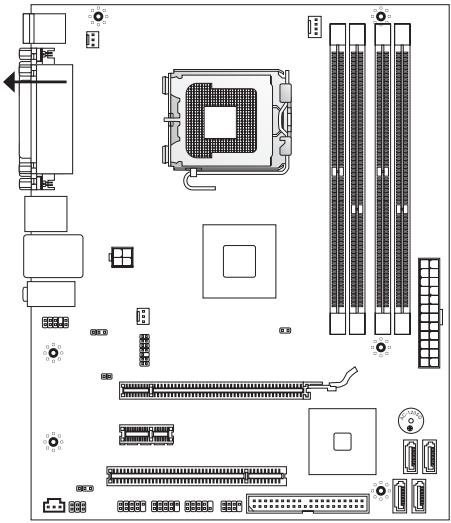
Refer above picture to install standoffs in the appropriate locations on chassis and then screw through the mainboard screw holes into the standoffs.
IMPORTANT
- To prevent damage to the mainboard, any contact between the mainboard circuit and chassis or unnecessary standoffs mounted on the chassis is prohibited.
- Please make sure there is no metal components placed on the mainboard or within the chassis that may cause short circuit of the mainboard.
REAR PANEL
The rear panel provides the following connectors:

HARDWARE SETUP
This section provides instructions on CPU and memory installation, as well as jumper settings on the mainboard. While doing the installation, be careful in holding the components and follow the installation procedures.
CPU & Cooler Installation Procedures for LGA775
When you are installing the CPU, make sure that you install the cooler to prevent overheating. If you do not have the CPU cooler, consult your dealer before turning on the computer.
The pin-pad side of LGA 775 CPU
The surface of LGA 775 CPU
Remember to apply some thermal paste on it for better heat dispersion.
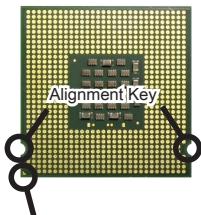
Yellow triangle is the Pin 1 indicator
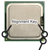
Yellow triangle is the Pin 1 indicator
Follow the steps below to install the CPU & cooler correctly. Wrong installation will cause the damage of your CPU & mainboard.
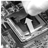
- The CPU socket has a plastic cap on it to protect the contact from damage. Before you install the CPU, always cover it to protect the socket pins.
- Remove the cap from the lever hinge side.
- The pins of socket reveal.
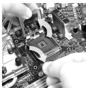
- Open the load lever.
- Lift the load lever up and open the load plate.
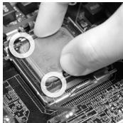
- After confirming the CPU direction for correct mating, put down the CPU in the socket housing frame. Be sure to grasp on the edge of the CPU base. Note that the alignment keys are matched.
- Visually inspect if the CPU is seated well into the socket. If not, take out the CPU with pure vertical motion and reinstall.
- Cover the load plate onto the package.
- Press down the load lever lightly onto the load plate, and then secure the lever with the hook under the retention tab.
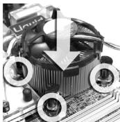
- Align the holes on the mainboard with the heatsink. Push down the cooler until its four clips get wedged into the holes of the mainboard.
- Press the four hooks down to fasten the cooler. Then rotate the locking switch (refer to the correct direction marked on it) to lock the hooks.
- Turn over the mainboard to confirm that the clip- ends are correctly inserted.
- Finally, attach the CPU Fan cable to the CPU fan connector on the mainboard.
IMPORTANT
- Read the CPU status in BIOS.
- Whenever the CPU is not installed, always protect your CPU socket pins with the plastic cap covered.
- Mainboard photos shown in this section are for demonstration of the CPU/ cooler installation only. The appearance of your mainboard may vary depending on the model you purchase.
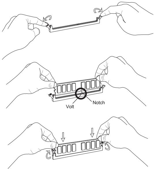
Installing Memory Modules
- The memory module has only one notch on the center and will only fit in the right orientation.
- Insert the memory module vertically into the DIMM slot. Then push it in until the golden finger on the memory module is deeply inserted in the DIMM slot. The plastic clip at each side of the DIMM slot will automatically close when the memory module is properly seated. You can barely see the golden finger if the memory module is properly inserted in the DIMM slot.
- Manually check if the memory module has been locked in place by the DIMM slot clips at the sides.
IMPORTANT
- In Dual-Channel mode, make sure that you install memory modules of the same type and density in different channel DIMM slots.
- To enable successful system boot-up, always insert the memory modules into the DIMM1 first.
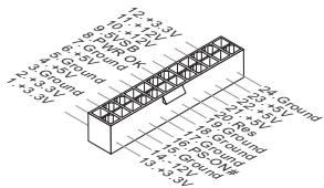
ATX 24-Pin Power Connector: JPWR1
This connector allows you to connect an ATX 24-pin power supply. To connect the ATX 24-pin power supply, make sure the plug of the power supply is inserted in the proper orientation and the pins are aligned. Then push down the power supply firmly into the connector.
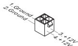
ATX 4-Pin Power Connector: JPWR2
This 4-Pin power connector is used to provide power to the CPU.
IMPORTANT
Make sure that all the connectors are connected to proper ATX power supplies to ensure stable operation of the mainboard.
IDE Connector: IDE1
This connector supports IDE hard disk drives, optical disk drives and other IDE devices.

IMPORTANT
If you install two IDE devices on the same cable, you must configure the drives to cable select mode or separately to master / slave mode by setting jumpers. Refer to IDE device documentation supplied by the vendors for jumper setting instructions.
Serial ATA Connector: SATA1 ~ 4
This connector is a high-speed Serial ATA interface port. Each connector can connect to one Serial ATA device.

IMPORTANT
Please do not fold the Serial ATA cable into 90-degree angle. Otherwise, data loss may occur during transmission.
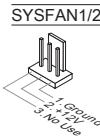
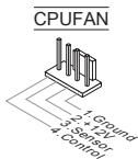
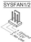
Fan Power Connectors: CPUFAN1, SYSFAN1, SYSFAN2
The fan power connectors support system cooling fan with +12V . When connecting the wire to the connectors, always note that the red wire is the positive and should be connected to the +12V ; the black wire is Ground and should be connected to GND. If the mainboard has a System Hardware Monitor chipset onboard, you must use a specially designed fan with speed sensor to take advantage of the CPU fan control.

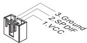
S/PDIF-Out Connector: JSP1
This connector is used to connect S/PDIF (Sony & Philips Digital Interconnect Format) interface for digital audio transmission.
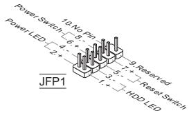
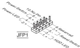
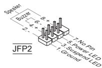
Front Panel Connectors: JFP1, JFP2
These connectors are for electrical connection to the front panel switches and LEDs. The JFP1 is compliant with Intel® Front Panel I/O Connectivity Design Guide.

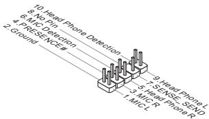
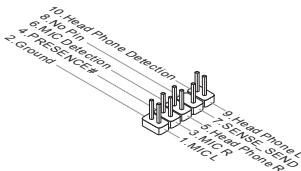
Front Panel Audio Connector: JAUD1
This connector allows you to connect the front panel audio and is compliant with Intel® Front Panel I/O Connectivity Design Guide.
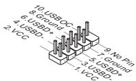
Front USB Connector: JUSB1, JUSB2
This connector, compliant with Intel® I/O Connectivity Design Guide, is ideal for connecting high-speed USB interface peripherals such as USB HDD, digital cameras, MP3 players, printers, modems and the like.
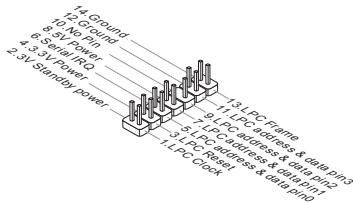
TPM Module connector: JTPM1
This connector connects to a TPM (Trusted Platform Module) module. Please refer to the TPM security platform manual for more details and usages.
Chassis Intrusion Connector: JCI1
This connector connects to the chassis intrusion switch cable. If the chassis is opened, the chassis intrusion mechanism will be activated. The system will record this status and show a warning message on the screen. To clear the warning, you must enter the BIOS utility and clear the record.

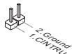
Clear CMOS Jumper: JBAT1
There is a CMOS RAM onboard that has a power supply from an external battery to keep the data of system configuration. With the CMOS RAM, the system can automatically boot OS every time it is turned on. If you want to clear the system configuration, set the jumper to clear data.
JBAT1
口口 1Keep Data
Clear Data
IMPORTANT
You can clear CMOS by shorting 1-2 pin while the system is off, then open it. Avoid clearing the CMOS while the system is on; it will damage the mainboard.
USB power Jumper:JUSB_PWM1
These jumpers are used to select USB ports powered by VCC5 or 5VSB. Set to 5VSB if you want them provide power in standby mode.
JUSBPW1
(for on-board USB connectors)


Close 1-3,2-4.
Keep USB power to VCC5 (default)

Close 3-5, 4-6.
Keep USB power to 5VB
IMPORTANT
If you set the jumper to 5VSB, the power supply must be able to provide at least 2A currents.
LAN, Front Audio EuP Jumper: JLANPW1, JAUD_PWM1
EuP(Energy-using Products) is a standard for reducing power consumption in standby mode. These jumpers are used to enable/ disable the EuP function of the LAN jack and the front audio connector.
JLANPW1
(for LAN jack)


Enable EuP
(default)
Disable EuP
JAUD_PWM1
(for JAUD1 connector)


Enable EuP (default)
Disable EuP
IMPORTANT
If you set the jumper to EuP, the Wake-on-LAN function will be disabled under S3, S4, S5 state.
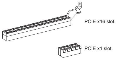
PCIE Slot
The PCIE slot supports the PCIE interface expansion card.
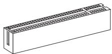
PCI Slot
The PCI slot supports LAN card, SCSI card, USB card, and other add-on cards that comply with PCI specifications.
IMPORTANT
When adding or removing expansion cards, make sure that you unplug the power supply first. Meanwhile, read the documentation for the expansion card to configure any necessary hardware or software settings for the expansion card, such as jumpers, switches or BIOS configuration.
PCI Interrupt Request Routing
The IRQ, acronym of interrupt request line and pronounced I-R-Q, are hardware lines over which devices can send interrupt signals to the microprocessor. The PCI IRQ pins are typically connected to the PCI bus pins as follows:
| Order Slot | 1 | 2 | 3 | 4 |
| PCI 1 | INT A# | INT B# | INT C# | INT D# |
BIOS SETUP
Power on the computer and the system will start POST (Power On Self Test) process. When the message below appears on the screen, press key to enter Setup.
Press DEL to enter SETUP
If the message disappears before you respond and you still wish to enter Setup, restart the system by turning it OFF and On or pressing the RESET button. You may also restart the system by simultaneously pressing , , and keys.
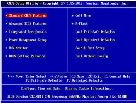
Main Page
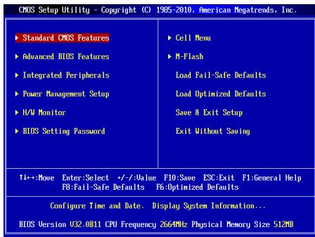
Standard CMOS Features
Use this menu for basic system configurations, such as time, date etc.
Advanced BIOS Features
Use this menu to setup the items of special enhanced features.
Integrated Peripherals
Use this menu to specify your settings for integrated peripherals.
Power Management Setup
Use this menu to specify your settings for power management.
H/W Monitor
This entry shows the status of your CPU, fan, warning for overall system status.
BIOS Setting Password
Use this menu to set BIOS setting Password.
Use this menu to specify your settings for frequency/voltage control.
M-Flash
Use this menu to read/ flash the BIOS from USB media device.
Load Fail-Safe Defaults
Use this menu to load the BIOS default values that are factory settings for system operations.
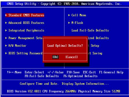
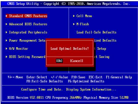
Load Optimized Defaults
Use this menu to load factory default settings into the BIOS for stable system performance operations.
Save & Exit Setup
Save changes to CMOS and exit setup.
Exit Without Saving
Abandon all changes and exit setup.
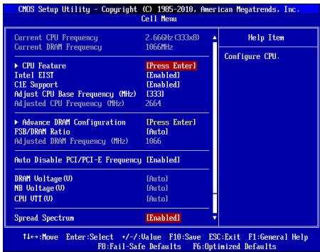
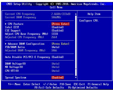
Current CPU/DRAM Frequency
It shows the current frequency of CPU/Memory. Read-only.
CPU Feature
Pressto enter the submenu
CPU Technology Support
Press to enter the submenu, that shows the technologies that the installed CPU supported.
Intel EIST
The Enhanced Intel SpeedStep technology allows you to set the performance level of the microprocessor whether the computer is running on battery or AC power. This field will appear after you installed the CPU which support speedstep technology.
C1E Support
To enable this item to read the CPU power consumption while idle. Not all processors support Enhanced Halt state (C1E).
Adjust CPU Base Frequency (MHz)
This item allows you to set the CPU Base clock (in MHz). You may overclock the CPU by adjusting this value. Please note the overclocking behavior is not guaranteed.
Adjusted CPU Frequency (MHz)
It shows the adjusted CPU frequency. Read-only.
Advance DRAM Configuration
Press to enter the submenu.
DRAM Timing Mode
Selects whether DRAM timing is controlled by the SPD (Serial Presence Detect) EEPROM on the DRAM module. Setting to [Auto By SPD] enables DRAM timings and the following related items to be determined by BIOS based on the configurations on the SPD. Selecting [Manual] allows users to configure the DRAM timings and the following related items manually.
CAS Latency (CL)
When the DRAM Timing Mode sets to [Manual], the field is adjustable. This controls the CAS latency, which determines the timing delay (in clock cycles) before SDRAM starts a read command after receiving it.
tRCD
When the DRAM Timing Mode sets to [Manual], the field is adjustable. When DRAM is refreshed, both rows and columns are addressed separately. This setup item allows you to determine the timing of the transition from RAS (row address strobe) to CAS (column address strobe). The less the clock cycles, the faster the DRAM performance.
tRP
When the DRAM Timing Mode sets to [Manual], the field is adjustable. This item controls the number of cycles for Row Address Strobe (RAS) to be allowed to precharge. If insufficient time is allowed for the RAS to accumulate its charge before DRAM refresh, refreshing may be incomplete and DRAM may fail to retain data. This item applies only when synchronous DRAM is installed in the system.
tRAS
When the DRAM Timing Mode sets to [Manual], the field is adjustable. This setting determines the time RAS takes to read from and write to a memory cell.
RTP
When the DRAM Timing Mode sets to [Manual], the field is adjustable. Time interval between a read and a precharge command.
tRFC
When the DRAM Timing Mode sets to [Manual], the field is adjustable. This setting determines the time RFC takes to read from and write to a memory cell.
fWR
When the DRAM Timing Mode is set to [Manual], the field is adjustable. It specifies the amount of delay (in clock cycles) that must elapse after the completion of a valid write operation, before an active bank can be precharged. This delay is required to guarantee that data in the write buffers can be written to the memory cells before precharge occurs.
tRRD
When the DRAM Timing Mode sets to [Manual], the field is adjustable. Specifies the active-to-active delay of different banks.
WTR
When the DRAM Timing Mode is set to [Manual], the field is adjustable. This item controls the Write Data In to Read Command Delay memory timing. This constitutes the minimum number of clock cycles that must occur between the last valid write operation and the next read command to the same internal bank of the DDR device.
FSB/DRAM Ratio
This item will allow you to adjust the ratio of FSB to memory.
Adjusted DRAM Frequency (MHz)
It shows the adjusted memory frequency. Read-only.
Auto Disable PCI/PCI-E Frequency
When set to [Enabled], the system will remove (turn off) clocks from empty DIMM and PCI slots to minimize the electromagnetic interference (EMI).
DRAM Voltage (V), NB Voltage (V), CPU VTT (V)
These items are used to adjust the voltage of CPU, Memory and chipset.
Spread Spectrum
When the motherboard's clock generator pulses, the extreme values (spikes) of the pulses create EMI (Electromagnetic Interference). The Spread Spectrum function reduces the EMI generated by modulating the pulses so that the spikes of the pulses are reduced to flatter curves. If you do not have any EMI problem, leave the setting at Disabled for optimal system stability and performance. But if you are plagued by EMI, set to Enabled for EMI reduction. Remember to disable Spread Spectrum if you are overclocking because even a slight jitter can introduce a temporary boost in clock speed which may just cause your overclocked processor to lock up.
IMPORTANT
- If you do not have any EMI problem, leave the setting at [Disabled] for optimal system stability and performance. But if you are plagued by EMI, select the
value of Spread Spectrum for EMI reduction.
- The greater the Spread Spectrum value is, the greater the EMI is reduced, and the system will become less stable. For the most suitable Spread Spectrum value, please consult your local EMI regulation.
- Remember to disable Spread Spectrum if you are overclocking because even a slight jitter can introduce a temporary boost in clock speed which may just cause your overclocked processor to lock up.
Load Optimized Defaults
You can load the default values provided by the mainboard manufacturer for the stable performance.
中国
#
ATX24FJ1JFJFJFJFJFJFJFJFJFJFJFJFJFJFJFJFJFJFJFJFJFJFJFJFJFJFJFJFJFJFJFJFJFJFJFJFJFJFJFJFJFJ
Press DEL to enter SETUP
Advanced BIOS Features
i
Integrated Peripherals
Ie nre r h e t i t t
Power Management Setup
i
H/W Monitor
BIOS Setting Password
iEe
Current CPU/DRAM Frequency
CPU Technology Support
命能達該句希德用電都達達達達達達達達達達達達達達達達達達達達達達達達達達達達達達達達達達達達達達達達達達達達達達達達達達達達達達達達達達達達達達達達達達達達達達達達達達達達達达
Intel EIST
怎龍頭Intel SpeedStep 指令號互連連賊則此號是AC裝置中間之號,隨隨隨隨隨隨隨隨隨隨隨隨隨隨隨隨隨隨隨隨隨隨隨隨隨隨隨隨隨隨隨隨隨隨隨隨隨隨隨隨隨隨隨隨隨隨隨隨隨隨隨隨隨隨隨隨隨隨隨隨隨隨隨隨隨隨隨隨隨隨隨隨隨隨隨隨隨隨隨隨隨隨隨隨隨隨隨隨隨隨隨隨隨隨隨隨隨隨隨隨随從。speedstep指令號之值為CPU指令號之值為1024位。
C1E Support
Adjust CPU Base Frequency (MHz)
Adjusted CPU Frequency (MHz)
Adjusted DRAM Frequency (MHz)
i
Auto Disable PCI/PCI-E Frequency
DRAM Voltage (V), NB Voltage (V), CPU VTT (V)
I
Spread Spectrum
Press DEL to enter SETUP
Advanced BIOS Features
Integrated Peripherals
BIOS Setting Password
Current CPU/DRAM Frequency
CPU Technology Support
Adjust CPU Base Frequency (MHz)
Adjusted CPU Frequency (MHz)
Adjusted DRAM Frequency (MHz)
DRAM Voltage (V), NB Voltage (V), CPU VTT (V)
Frontpanel Anschlüsse: JFP1, JFP2
Press DEL to enter SETUP
Advanced BIOS Features
Integrated Peripherals
BIOS Setting Password
Current CPU/DRAM Frequency
CPU Technology Support
Adjust CPU Base Frequency (MHz)
Adjusted CPU Frequency (MHz)
Adjusted DRAM Frequency (MHz)
DRAM Voltage (V), NB Voltage (V), CPU VTT (V)

KOMHOENTbI CNCTEMHOI NaTbI
XAPAKTEPNUCTIKI
Пюцeccор
Плесочев Intel® Core™ 2 Quad/Core™ 2 Duo/ Pentium® Dual-Core/ Celeron® B кОНТКУТЕ ВAO775
Подевжka 4-КоТАктHorO ВЕнтулотаю рpoцeccocpaс Функшeи
уразвени_CСКОРСТБВВрашени
(ДЯп поуеняй поного сизда подевжьаembIX CPU, nocetite caT
http://www.msi.com/index.php?func=cpuform2)
FSB
1333 M
Unncet
CebepbMocT: Intel G41
IOxHbIMoCT:Intel ICH7
NamrTb
2 cnoTa DDR2 667/800/1066(OC) DIMM (8Fb Max)
2cnoraDDR380/1066/1333(OC) DIMM (8FB Max)
(3a dojolnHteneBnoHnΦopMaueo o cobmctmbx KOMNOHeTax, nocetnte camt http://www.msi.com/index.php?func=testreport)
LAN
ПлобержхALAN10/100/1000Fast Ethernet начincete Realtek®8111E (G41M-P43Combo)
- Побдержka LAN 10/100 Fast Ethernet на чиncete Realtek® 8105E (G41M-P33 Combo)
Aydno
UnterpnoBaHbIy UInceT Realtek ALC662
Iopndepkka 5.1 kaHnBHoro ayDIO BOxOda
CoBmecTmocb co cneuΦkauei Azalia 1.0
IDE
1 nopT IDE ha yuncete Intel® ICH7
Подэржka рекимов pa60ты Ultra DMA 66/100, PIO & Bus Master
SATA
4 nopTa SATA 3Γ6/c Ha unncete Intel® ICH7
KOHHeKTopbI
3aDnei nane I/O
-1PS/2npTMbIu
-1PS/2npTknabnAtypb
- 1 napannenbnyn nopT
- 1 nocneIOBATEnbHb nopt
- 1 nopT VGA
- 4 nopTa USB 2.0
- 1 pa3beM LAN
-3 3BykoBbIX pa3bema C rno6kIm nepeHa3HaueHnEM
Pa3bEmbl,yctaHOBnEHHbIeHa nNaTe
- 2 pa3bema USB 2.0
- 1 pa3bem S/PDIF-Out
- 1 pa3bem Дя подкючени aydno Ha nepeДнй панели
- 1 pa3bem DaTcNka OTKpbBaHnna Kopnyca
- 1 pa3bem TPM
Cnotbl
1 cnot PCIE x16
1 cnot PCIE x1
1 cnotPCI, noDpejka nHTeppeca PCI uHbI c nTahm 3.3V/5V
ΦopM ΦakTop
Micro-ATX (19.8 cm x 24.4 cm)
KpennneHne
6 OTBepCTn DnKpePnEHHa
Pazbem nopepkjBaAeT noeknlochHne JxctKHX DnCKOB IDE, ONTHeCKNX DnCKOB nDpyrKIX IDE yctpOCTB.
BHIMMAHVE
Pnpn knoeHHn DByx yctpoiBt H aDHom Kabe, cnEpyet yctaHOBntb yctpoiCTBa B pekim master / slave nocpeDCTBOM yctaHOBKn peMbeYkn. 3a nHTcPKIqHMM oBpaTHeB K dOKyMeHTaHm IZrOToBHTen yCTpOCTBa.
Pazem Serial ATA: SATA1~4
Pa3bEM Serial ATA - 3TO BbICOKOcKOpocTHoN oPT nHTepeFeica Serial ATA. 3ToT pa3bEM PO3BOJAREnIOKNIOHt ToIbKO ONoHO yCtpoCTBO Serial ATA.

BHIMMAHNE
U36aertepe3kIXnI8bO KaBcER Serial ATA.B npOTBHOM cHyae MOrYT BO3HNKHTy notepn dAnhXp np nepeDaue.
Pazbem nitaHn BENTnIaTOpOB: CPUFAN1, SYSFAN1, SYSFAN2
Pa3bEmbI pIITAHNBEBHTINTAPOP BOIDepKXBAAOT BENTHJLPTbC nITAHEM +12B. PnPoiNDkIouEHNOE 60xDIOMO NOMHTb, YTO KpCaHbN npOBoD oNkIOOaHuTcK KUHNE +12B,a cepHB- K ZEMNe GND.EcNc CICTeMHNA PtNaIe COdEKHt MINKOCXEMPY annapathrO MOHOTPOHnA, Heo6xoDMIO HcONlOB3OBaTb CneuAlNbHBe BENTINTAPOBc DaTcNKOM cKOPOCTn DnpeaIN3aunm FyHKUynPABENEH BENTINTAPOP.
Pa3bem S/PDIF-Out:JSP1
3TOT pabem nconbetya for nojdknoyehn uHtpecpa S/PDIF (Sony & Philips Digital Interconnect Format) para nepeda 3ya k uFpobom fopmatre.

PazbemblnnoKlnouHnepeedne naheJFP1,JFP2
3TN pa3bEMbl o6ceNcHBAOT nOdknOueHne KHOOK u HmDkKatopOB nepeHne naHEn. JFP1 cooTBeTCTBye t cneuФнkaunl Intel® Front Panel I/O Connectivity Design Guide.
Aydno pa3bembl nepednei nanei:JAUD1
PazEmoNBJT neOKnIOHHT ayDnO NaepeDHeN paENHeN. OH COBTETCTBYET cneUHkAaKuINl lE Front Panel I/O Connectivity Design Guide.
Pazbem USB nepedne JUSB1, JUSB2
Pa3bem, KOTOpBIO COBMEcTmO Co cneuΦnKaUeH IntelI/O Connectivity Design Guide, upeAeH N I POKIHOeHry TAKHX BILCOKOCPOCTbIX NepiΦePNIbIX yctpoCTB KAK USB HDD, UΦpaBbIX KaMep, MP3 pIeepoB, pNHTepoB, MoDEM oT. T.D.

Pa3bem TPM MoynjA: JTPM1
3T0t pasbem npdehaaehn paraodknuehen TPM (Trusted Platform Module) Modyna. 3a doonnoHntelbHOH mHΦopmaueH n BO3MOxHCTMn HcnoIb3oBAHn 6obatTeB k pyKOBODCTBy npatfOpmbl 6e3oNa3OCHOT TPM.

Pazbem dattnka otKpbBaHmKopnyca: JCI1
K 30my KOHNkEToPO NOKJIIOuAeTcra Ka6eb DaTtNka OTKpbIBaHnna KOpNyca, yctahOBHeNbB KOpNye. PnO tOKPBbAHn NopNcyra eO mExaHn3M AKTNb3NPyETc.CsTeMa 3aONMOHaIe TTO cObItne H bJaTaP npDynpKeJHne Ha 3kape. PpDynpKeJHne MoXHO OTKIOuHTb N aCTropiKaX BiOS.
Main Page (OchOBHoe MeHIO)
Standard CMOS Features (CTaHdapTbIe yHKm CMOS)
3TO MEHO N03BOJNERT YCTAHOBINTB OCHOBHbIe napAMETpb KoHNyprapaunCIN CHTEMbl (dAty, BPMeR, n T.D.).
Integrated Peripherals (BcTpoeHHbIe nepHepnHbIe yCTpoNcta)
3ToMeHIOIcnpbIaByeTcAJnHaCTpOIKnnapaMetPOB BCTpoEHhX nepiFepeHHbIX yuctoCTb.
Power Management Setup (Hactpoika ynpablenia nitaHnem)
3TO MEHIO NO3BOJRAET 3aDaTb npaMeTpbl ynpaBHeHnI NITAHm CnCTEmbl.
H/W Monitor (MoHTop annapaTHoY actn)
3TOT nyHKT OTo6paxKaet COCTOHNe annapathOn qactn PK.
BIOS Setting Password (Паров дocунka К actpoikam BIOS)
3To MeHIO nCnOJb3yETcA, TTO6bl 3aDaTb napoiB.
3TO MEHIO NOBBOJET YNPABTb TAKTOBIMu cactOTAMn HANPRAKENIAmPi paoRHOCTCMBt.
M-Flash
IcnoIb3yETcIaIyTeHnI/ npOuINBkBIOS c USB media device.
Load Fail-Safe Defaults
3To mEnIO nCNOIyETcA n3gpy3n 3aHneHHBIOS,yCTaHOBENbIX npno3ABTIDENTeM nTcAStbHbN paBOThi CNTeMbI.
Load Optimized Defaults (YctaHOBnTb ONTMaJIbHbIe HAcTpOKn)
3To MeHIO ICNOpIbEyctar DcY JCTAHOBK INACTPOEK INAGOTBENTELI DnA ONTMALBHPOIN3BODENTBLHOCTN CHTEMHNO PnATb.
Save & Exit Setup (BbIXoD c coXpaHHeM hAcTpoE)
3aIncb n3MeHEni B CMOS n BbIXoN i3 peKIma NaCTpOKn.
Exit Without Saving (BbIXoD 6e3 coxpaHene)
OTMeHa BCEx N3MeHeHn I BbIXoD n3 peKIma NaCTpoKn.
Cell Menu
Current CPU/DRAM Frequency
3T0T pyNKT nokazbIaET TeKuyu cHactOTy CPU nCKOPoCTb nAMrIn. TOnbKO dYTHeN.
CPU Feature
HaxmteДЯ BXOda B NOmEnIO.
CPU Technology Support
Haxmte IxgXbOaB NO bMnEHO B noMnEHO nOKa3aHb TEHXoJrnn, KOTOpBeNoNDepKXBaaet YctahOBHeNb CPU.
Intel EIST
TexHONORIy Enhanced Intel SpeedStep no3B0nIeT yctAHoNtIb yOpeBHe npon3BODiTeJIbHOCTNI MKNpOOnpoEccopa. 3ToT nyHKT nOBJETcnc oNoJIe yctAOHKn pIOeCCOPa, KOTOpB noNDaePKBaET texHONORIO SpeedStep.
C1E Support
BkHOnUte 3OTI NYHKT IJN CMOTpeHHa COCTOHN HA 3HePrc6epeKEnH CPU, KOrda OH he pa60taet. He Bce npocecoppb noDepxmbaIOT Enhanced Halt state (C1E).
Adjust CPU Base Frequency (MHz)
3TOT nyHKT nO3BONAT yCTAHOBITb TAKTOBYIO YACTOTy Base clock CPU (b MFU).
IVmHeHne 3TOrO napAMETpa o6cNeuBaET Bo3MOKHOCT pa3roHA CPU.
BHmAHue, BO3MOXHOCTb ycNeuHoro PA3ROHa he rapaHTpYeTc.
Adjusted CPU Frequency (MHz)
3TOT nyHKT noka3bIbaeT kcyuio qactOty CPU. TOnbKO dnyTeHnA.
Advance DRAM Configuration
HaxmteДЯ BXOda B NOmEnIO.
DRAM Timing Mode
OnpeIeIeT 6ydt Np BpeHHeBHe napaMeTpbl DRAM KOHTponIpObaTcB daHbMn n3 SPD (Serial Presence Detect) EEPROM haMoDyne DRAM. PInb ByIbObe 3haueHm [Auto By SPD], BpeHHeBHe napaMeTpbl DRAM, BkIOuHa yNKTb MeHIO, nepeUcnEhHe bHKe, ycTaHbJIbAoiTc BIOS B COOTBeTCTBn C daHbMn n3 SPD. PInp yctahOBke 3haueHn [Manual]. 3tOt nyHK T03BONIeB BPuyHyIO perynipoBaTb BpeHHeBHe napaMeTpbl DRAM DOctYnIbEs B 3TOM MEHO.
CAS Latency (CL)
Pn yctahOBke DRAM Timing Mode B [Manual]. 30T nyHK tcaHOBtC8OCTyNtBm. OH KOHTponiPyET Bpemr 3aedePkKn CAS, KOTopoe onpeIenre TepnoD (B TakTx rhepeHaTopora) Mexdy nOnyuHeHem SDRAM KomaHdbu THeHn Hauanom ee BbInonHHeHn.
tRCD
Pn yctahOBke DRAM Timing Mode B [Manual], 3OT NpHKT cTahOBITcOdoTynbIM. Pn pereheepaunz 3apraDRAM, cTPOKNI cTOn6bIb aApceCyTOcpa3dEJIbHO. 3OT NpHKT n03BONJIeBam OnpedeJIbBpeMn nepexoJa OT RAS (CTpo6 aPeCA cTPOKI) K CAS (cTpo6 apeca cTOn62a). Yem MehIe TaKToB, TEM 6bIcTepe pa6ota DRAM.
tRP
Пуг установ DE RAM Timing Mode B [Manual], 30ТУNYKT сановптудддддддддддддддддддддддддддддддддддддддддддддддддддддддддддддддддддддддддддддддддддддддддддддддддддд徳сьгьмь дярпснлб.dma OTOT NYKTH KOHTPONIPPYET KOINTCBO TAKTOB,псесdэвгьмь dярпснлб.dma Row Address Strobe (RAS).Есп bIDБЕРСТСДЕСТАТСОЧЕDE
В维护дяп.TORO,ТУББI RAS habран Heo6xOdIMbIЗЗад,pereHepaIa DRAM moKet OKa3aTbCHe NpRbEChn K npBecTe N pOtepeДаньХ.3ToT nyHKT prPmEHMn,TOnBJKO korga B cIstcEme yctahONbHe aCINXPOHNHAR.DRAM.
tRAS
Pn yctahOBke DRAM Timing Mode B [Manual], 3T0T nyHKT cTahOBtCAOCTyHbIM. 3Ta yctahOBKa onpeIeJIeR BPMA, KOtopoe RAS 3aTpaUHbAET Ha TcHENIE n 3aIINCB B rHeIKy NpAMrTI.
tRTP
Pn yctahOBke DRAM Timing Mode B [Manu], 3OT nyHK tchAOBtCA DOCTyINHb. BpeMeHHN hHTepBAPm EMKdY KOmaHdAmn TCHEnu nPeD3AaPra.
tRFC
Pn yctahOBke DRAM Timing Mode B [Manual], 3OT NTyNKT CTAHOBITCAOCTYHbM.3Ta yctahOBKa ONpeDelaert BPMe, KOtopoE RFC 3aTpaYHbaET Ha TcHENe H3aNNbcB R aHeyKy NpamTt.
tWR
Ipy yctahOBke DRAM Timing Mode B [Manual], 30T nyHK TchAOBnTCOCTyTNbIM. 3Ta yctAHOBKa onpeDeneR BPemEHHy 3aepKky (B taktx rereHapota), KOTOPAR BInONHETcMEXdy 3aBepHeHmE DeiCTBHTenbHO onepaunz anINCN IN pnd3apdOM AKTINBOHRo 6hAnka. 3Ta 3aepKka Heo6XoIMHa, YTOby rapaHTnpoBaTb, YTO daHNbIE B 6yfepaX 3aNcHyc YeJeOT nonAteB Y beyekn parnTOnOpNo I npde3apDa.
tRRD
Пуг сановке DRAM Timing Mode B [Manual]. STOTNYHKT CTAHOBITCA DOCTYNHbM. ON oppepejret 3aepkky OT AKTNBHOK KAKTNBHOMY COCTOHNO ДЯ раньхбankOB.
tWTR
Pn yctahOBke DRAM Timing Mode B [Manual], 3TOT nyHK tCTahOBtca DoctynbIM. 3TOT nyHK KOHTpOJIpyET 3aedpKxy MExdy Write Data In n Read Command Delay. Oha onpeJeT MInHMmaIbHOe KOnIcTeBTO TAKTOB, KOTOpoe DOxKnIO npOITM MExdy NocpeDHe DteCBTIenbHO n Oepauné aannci n CneDyUoie KOMaHDoN YTeHn I qOnHO r TOBO Hs6BaHkA yctpoiCTBa DDR.
FSB/DRAM Ratio
3TOT NHTK NT0BONET PERyINPOBaTB KO3ΦΦNlMENT MEXDy ChACTOTAMN FSB IN NAMTBI.
Adjusted DRAM Frequency (MHz)
3TOT nyHKI NOKa3bIaET 3NaueHne yAcToIbI naMrtn. TOnbKO dIyUteHnA.
Auto Disable PCI/PCI-E Frequency
Pn yctaHOBKe 3aHcHEna [Enabled] CnCTeMa OTKnOHT HeICNpONb3yEmbe pa3bEmb npaTn pa3bEmb DI MM nPCI, qTO npIbeET K cHKeHIO yOBHn 3neKTporamTHbIX nomex (EMI).
DRAM Voltage (V), NB Voltage (V), CPU VTT (V)
3TOT nyHKT no3BOJAEr perynipoBaTB HanpJKeHne CPU, naMaTn uYnceta.
Spread Spectrum
Tak kak TAKTOBBI rHE hepatopC nCTEMHNO INaIbTI MMNylbChbl, To ero pa60ta Bb3bIaet 3eKtpomarHtHbe nomexn - EMI (Electromagnetic Interference). FyHKnlae Spread Spectrum CnHKnAeT 3nOnomexn, rHepeRpyr crnaKeHHBe IMNylbcI. EcnI y Bac Het np6bEm c NOMexAmn, octabTe 3hauYeHne [Disabled] (3anpeLHeO) dNra nyuie StcAbHbOncn n PnpO3BOuHTelbOncn. Ondako, ecnI y Bac BO3HNaOT 3eKTPomarHtHbe NOMexn, papeWte NcONb3OBAHne 3ToI fYHKnIy, yctAOHBnB [Enable] (pa3peSeHO). He 3a6byTe 3anPeNTn IcNbONb3OBAHne FyHKnIy Spread Spectrum, ecnI bIy (pa3aONHReTe) cNCTeMHyIO nAty. 3To hEO6xOIMO, taK kak daxe HboBsw Ope6eB rCngHAnOB TAKTOBOr rREhepatoM POMeT npVEcTn OKt43y (pa3OrHaHNoEg) npOceccopa.
BHIMAHHE
- Ecnny y Bac Het npobnem c nomexamn, octabte 3nauehme [Disabled] (aanpeuho) nianyue stcbnBHOCTN n pno3BODHTNBHOCTN. Ondako, ecnny y Bac BO3HnAoiT neKETPOMarHnTHbIe nomexn, BbIbepTe Spad Spectrum dny xmyEHEWHeN.
* Yem 6oIbIwe 3aHaeHne Spread Spectrum, tem Hnke bdyet ypoBHeN 3eKTPOMAHHTHbIX NOMEX, HO CNCTEMA cTahET MeHec TcAunbHOi. IyBa IbIObe NOxOJaIeO 3aHaeHne Spread, CMeTBeC o 3aHaeHneMm ypoBHeN 3eKTPOMAHHTHbIX NOMEX, yCTAHOBJIHHbIX 3aKOHDoTeJIbCTCBOM.
- He 3a6yblte 3a9pntHb IcnoIb3oBAnHe ΦHyKcMn Spread Spectrum, ecn bIy [pa3roHnEe] CnCTeMHy InpA. 3To Heo6xOIMMo, TAK KaK DaJke HeoNlsuon dpe6e3r CrngHAnob TaTOKTOBOr reHepaTopa MoKeT npBecT N OTKa3y [pa3orHaHHoro] npOeccopa.
YctaHObKa 3HaueHnI IO yMOJIaHnIO
IaTc76bHbNo paBoTbblCTMebbl BbMoKetee 3aRyBnHn HactPojki BIOS noUmyHAnu, yctaONbAHNHeIe npO13BOdITenEM CHTcEMHO nnPbI.
简体中文
简介
Press DEL to enter SETUP
DRAM Voltage (V), NB Voltage (V), CPU VTT (V)
1個PCIEx16插槽
1個PCIEx1插槽
1個PCI插槽,支援3.3V/5VPCI匯流排
尺寸
Micro-ATX (19.8 cm X 24.4 cm)
裝機
6個裝機孔
Press DEL to enter SETUP
(按DEL键進入設定選單)
Advanced BIOS Features
使用本選單設定特殊的進階功能。
Integrated Peripherals
使用本選單設定整合型週邊裝置。
Power Management Setup
使用本選單設定電源管理。
H/W Monitor
BIOS Setting Password
使用本選單設定BIOS密碼
本選單可指定頻率及電壓控制。
M-Flash
Current CPU/DRAM Frequency
CPU Technology Support
Adjust CPU Base Frequency (MHz)
Adjusted CPU Frequency (MHz)
本項顯示調整後CPU的頻率。唯讀。
Advance DRAM Configuration
按下键,即可進入子選單。
DRAM Timing Mode
Adjusted DRAM Frequency (MHz)
本項顯示調整後記憶體的頻率。唯讀。
Auto Disable PCI/PCI-E Frequency
DRAM Voltage (V), NB Voltage (V), CPU VTT (V)
本項設定記憶體、北橋及CPU的電壓。
Spread Spectrum
This is the first time you can use this tool.
Integrated Peripherals (內藏機能の設定)
CPU Feature (CPUの機能)
CPU Technology Support (CPUtek/口Jsaboe-1)
C1E Support (C1E示一卜)
Adjusted CPU Frequency (MHz) (調整たCPU周波数)
DRAM Voltage (V), NB Voltage (V), CPU VTT (V)

