
970A-G46 - Motherboard MSI - Free user manual and instructions
Find the device manual for free 970A-G46 MSI in PDF.
| Product Type | ATX Motherboard |
| Brand | MSI |
| Model | 970A-G46 |
| CPU Socket | AM3+ (compatible with AM3) |
| Supported Processors | AMD Phenom II, Athlon II, Sempron |
| Chipset | AMD 970 + SB950 |
| Memory Type | DDR3, up to 2133 MHz (OC) |
| Maximum Memory Capacity | 32 GB (4 x DIMM) |
| Number of Memory Slots | 4 x DDR3 DIMM |
| Multi-GPU Support | AMD CrossFireX, NVIDIA SLI |
| Expansion Slots | 2 x PCIe 2.0 x16, 2 x PCIe 2.0 x1, 2 x PCI |
| Audio | Realtek ALC892, 8-channel HD |
| LAN | Realtek RTL8111E, 10/100/1000 Mbps |
| SATA Ports | 6 x SATA 6 Gb/s (RAID 0/1/5/10) |
| USB Ports (Rear) | 2 x USB 3.0, 6 x USB 2.0 |
| Power Connectors | 24-pin ATX, 8-pin CPU |
| Dimensions | ATX (22.5 cm x 30.5 cm) |
| BIOS Features | Click BIOS II, OC Genie, Live Update |
Frequently Asked Questions - 970A-G46 MSI
User questions about 970A-G46 MSI
0 question about this device. Answer the ones you know or ask your own.
Ask a new question about this device
Download the instructions for your Motherboard in PDF format for free! Find your manual 970A-G46 - MSI and take your electronic device back in hand. On this page are published all the documents necessary for the use of your device. 970A-G46 by MSI.
USER MANUAL 970A-G46 MSI
The material in this document is the intellectual property of MICRO-STAR INTERNATIONAL. We take every care in the preparation of this document, but no guarantee is given as to the correctness of its contents. Our products are under continual improvement and we reserve the right to make changes without notice.
Trademarks
All trademarks in this manual are properties of their respective owners.
MSI® is registered trademark of Micro-Star Int'l Co., Ltd.
NVIDIA® is registered trademark of NVIDIA Corporation.
ATI® is registered trademark of AMD Corporation.
AMD® is registered trademarks of AMD Corporation.
Intel® is registered trademarks of Intel Corporation.
Windows® is registered trademarks of Microsoft Corporation.
AMI is registered trademark of American Megatrends Inc.
Award® is a registered trademark of Phoenix Technologies Ltd.
Sound Blaster® is registered trademark of Creative Technology Ltd.
Realtek® is registered trademark of Realtek Semiconductor Corporation.
- JMicron® is registered trademark of JMicron Technology Corporation.
Netware® is registered trademark of Novell, Inc.
Lucid® is trademark of LucidLogix Technologies, Ltd.
VIA® is registered trademark of VIA Technologies, Inc.
■ ASMedia® is registered trademark of ASMedia Technology Inc.
iPad, iPhone, and iPod are trademarks of Apple Inc.
Revision History
| Revision | Revision History | Date |
| V2.0 | First release | 2011/12 |
Technical Support
If a problem arises with your system and no solution can be obtained from the user's manual, please contact your place of purchase or local distributor. Alternatively, please try the following help resources for further guidance.
Visit the MSI website for technical guide, BIOS updates, driver updates, and other information: http://www.msi.com/service/download
Contact our technical staff at: http://support.msi.com
Safety Instructions
Always read the safety instructions carefully.
- Keep this User's Manual for future reference.
- Keep this equipment away from humidity.
Lay this equipment on a reliable flat surface before setting it up.
- The openings on the enclosure are for air convection hence protects the equipment from overheating. DO NOT COVER THE OPENINGS.
- Make sure the voltage of the power source is at 110/220V before connecting the equipment to the power inlet.
- Place the power cord such a way that people can not step on it. Do not place anything over the power cord.
Always Unplug the Power Cord before inserting any add-on card or module.
All cautions and warnings on the equipment should be noted.
- Never pour any liquid into the opening that can cause damage or cause electrical shock.
If any of the following situations arises, get the equipment checked by service personnel:
The power cord or plug is damaged.
Liquid has penetrated into the equipment.
The equipment has been exposed to moisture.
The equipment does not work well or you can not get it work according to User's Manual.
The equipment has been dropped and damaged.
The equipment has obvious sign of breakage.
DO NOT LEAVE THIS EQUIPMENT IN AN ENVIRONMENT ABOVE 60^ (140^) IT MAY DAMAGE THE EQUIPMENT.
FCC-B Radio Frequency Interference Statement
This equipment has been tested and found to comply with the limits for a Class B digital device, pursuant to Part 15 of the FCC Rules. These limits are designed to provide reasonable protection against harmful inter

ference in a residential installation. This equipment generates, uses and can radiate radio frequency energy and, if not installed and used in accordance with the instructions, may cause harmful interference to radio communications. However, there is no guarantee that interference will not occur in a particular installation. If this equipment does cause harmful interference to radio or television reception, which can be determined by turning the equipment off and on, the user is encouraged to try to correct the interference by one or more of the measures listed below.
Reorient or relocate the receiving antenna.
- Increase the separation between the equipment and receiver.
- Connect the equipment into an outlet on a circuit different from that to which the receiver is connected.
Consult the dealer or an experienced radio/television technician for help.
Notice 1
The changes or modifications not expressly approved by the party responsible for compliance could void the user's authority to operate the equipment.
Notice 2
Shielded interface cables and A.C. power cord, if any, must be used in order to comply with the emission limits.
VOIR LA NOTICE D'INSTALLATION AVANT DE RACCORDER AU RESEAU.

Micro-Star International
MS-7693
This device complies with Part 15 of the FCC Rules. Operation is subject to the following two conditions:
1) this device may not cause harmful interference, and
2) this device must accept any interference received, including interference that may cause undesired operation.
Battery Information

European Union:
Batteries, battery packs, and accumulators should not be disposed of as unsorted household waste. Please use the public collection system to return, recycle, or treat them in compliance with the local regulations.

Taiwan:
For better environmental protection, waste batteries should be collected separately for recycling or special disposal.
廢電池請回收
California, USA:
The button cell battery may contain perchlorate material and requires special handling when recycled or disposed of in California.
For further information please visit:
http://www.dtsc.ca.gov/hazardouswaste/perchlorate/
CAUTION: There is a risk of explosion, if battery is incorrectly replaced.
Replace only with the same or equivalent type recommended by the manufacturer.
Chemical Substances Information
In compliance with chemical substances regulations, such as the EU REACH Regulation (Regulation EC No. 1907/2006 of the European Parliament and the Council), MSI provides the information of chemical substances in products at:
http://www.msi.com/html/popup/csr/evmptrtt_pcm.html
BSMI EMI 聲明
警告使用者:
WEEE (Waste Electrical and Electronic Equipment) Statement
ENGLISH
To protect the global environment and as an environmentalist, MSI must remind you that...
Under the European Union ("EU") Directive on Waste Electrical and Electronic Equipment, Directive 2002/96/EC, which takes effect on August 13, 2005, products of "electrical and electronic equipment" cannot be discarded as municipal wastes anymore, and manufacturers of covered electronic equipment
will be obligated to take back such products at the end of their useful life. MSI will comply with the product take back requirements at the end of life of MSI-branded products that are sold into the EU. You can return these products to local collection points.

DEUTSCH
Mainboard Specifications
Processor Support
■ AMD® Phenom™ II, Athlon™ and Sempron processor in the AM3/ AM3+ package. (For the latest information about CPU, please visit http://www.msi.com/service/cpu-support)
Chipset
AMD® 970 & SB950 chipset
Memory Support
4x DDR3 DIMMs support DDR3 2133*(OC)/ 1866/ 1600/ 1333/ 1066 DRAM (32GB Max)
Supports Quad-Channel mode, one DIMM per channel (*OC = OverClocking, for more information on compatible components, please visit http://www.msi.com/service/test-report)
LAN
Supports LAN 10/100/1000 Fast Ethernet by Realtek® RTL8111E
Audio
Integrated HD audio codec by Realtek® ALC892
8-channel audio with jack sensing
SATA
6x SATA 6Gb/s ports by AMD® SB950
RAID
SATA1~6 support RAID 0/1/5/10 by AMD® SB950
USB 3.0
2x USB 3.0 rear IO ports by ASMedia® ASM1042
Multi-GPU
Supports ATI CrossFireX™ Technology
Supports NVIDIA® SLITM Technology
Connectors & Buttons
Back panel
- 1x Optical S/PDIF-Out port
- 1x PS/2 keyboard/ mouse port
- 1x Serial port
- 6x USB 2.0 ports, 2x USB 3.0 ports (970A-G46)
- 8x USB 2.0 ports (970S-G46)
- 1x LAN port
- 6x audio ports
On-Board
- 3x USB 2.0 connectors
- 1x TPM Module connector
- 1x Front Panel Audio connector
- 1x Chassis Intrusion connector
- 1x S/PDIF-out connector
Slots
2x PCIe 2.0 x16 slots
- PCI_E2 supports up to PCIe x16 speed (when PCI_E4 is empty) or PCIe x8 speed (when PCI_E4 is installed)
-PCI_E4 supports up to PCIe x8 speed
2x PCIe 2.0 x1 slots
2x PCI slots, support 3.3V/ 5V PCI bus Interface
Form Factor
ATX (22.5 cm × 30.5 cm)
Mounting Screw Holes
6x mounting holes
If you need to purchase accessories and request the part numbers, you could search the product web page and find details on our web address below http://www.msi.com/index.php
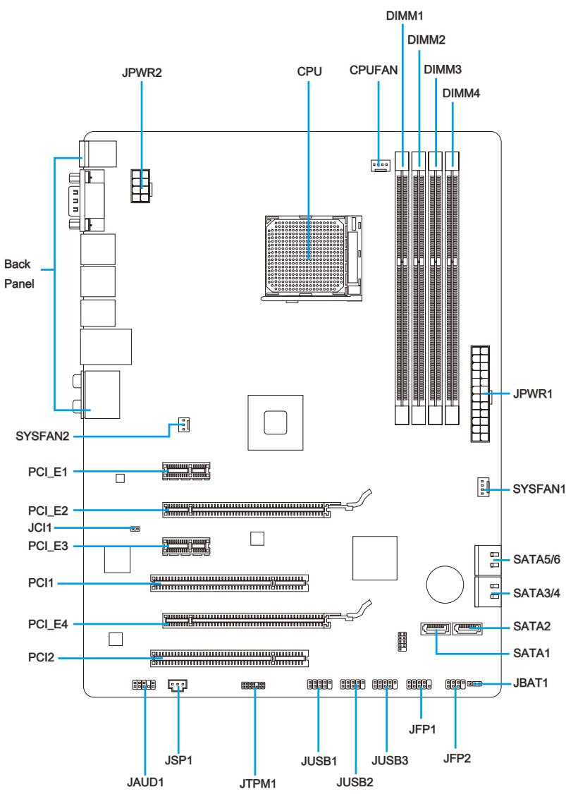
Connectors Quick Guide
Connectors Reference Guide
| Port Name | Port Type | Page |
| Back Panel | En-6 | |
| CPU | AM3+ CPU Socket | En-8 |
| CPUFAN | CPU Fan Connector | En-17 |
| JAUD1 | Front Panel Audio Connector | En-18 |
| JBAT1 | Clear CMOS Jumper | En-21 |
| JCI1 | Chassis Intrusion Connector | En-19 |
| JFP1, JFP2 | Front Panel Connectors | En-18 |
| JPWR1 | ATX 24-pin Power Connector | En-12 |
| JPWR2 | ATX 8-pin Power Connector | En-12 |
| JSP1 | S/PDIF-Out Connector | En-20 |
| JTPM1 | TPM Module connector | En-20 |
| JUSB1~3 | USB 2.0 Expansion Connectors | En-19 |
| PCI1,2 | PCI Expansion Slots | En-15 |
| PCI_E2,4 | PCIe x16 Expansion Slots | En-15 |
| PCI_E1,3 | PCIe x1 Expansion Slots | En-15 |
| SATA1~6 | SATA 6Gb/s Connectors | En-16 |
| SYSFAN1~2 | System Fan Connectors | En-17 |
Back Panel Quick Guide
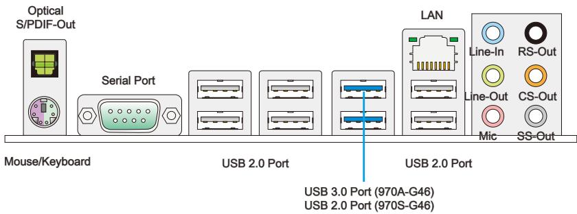
Optical S/PDIF-Out
This S/PDIF (Sony & Philips Digital Interconnect Format) connector is provided for digital audio transmission to external speakers through an optical fiber cable.
Mouse/Keyboard
A combination PS/2® mouse/keyboard DIN connector for a PS/2® mouse/keyboard.
> Serial Port
The serial port is a 16550A high speed communications port that sends/ receives 16 bytes FIFOs. You can attach a serial mouse or other serial devices directly to the connector.
USB2.0Port
The USB 2.0 port is for attaching USB 2.0 devices such as keyboard, mouse, or other USB 2.0-compatible devices.
USB 3.0 Port (970A-G46)
USB 3.0 port is backward-compatible with USB 2.0 devices. It supports data transfer rate up to 5 Gbit/s (SuperSpeed).
Important
In order to use USB 3.0 devices, you must connect to a USB 3.0 port. If a USB cable is used, it must be USB 3.0 compliant.
LAN
The standard RJ-45 LAN jack is for connecting to a Local Area Network (LAN).

| LED | Color | LED State | Condition |
| Left | Yellow | Off | LAN link is not established. |
| On(Steady) | LAN link is established. | ||
| On(FLASHING) | The computer is communicating with another computer on the network. | ||
| Right | Green | Off | 10 Mbits/sec data rate |
| On | 100 Mbits/sec data rate | ||
| Orange | On | 1000 Mbits/sec data rate |
Audio Ports
These connectors are used for audio devices. The color of the jack refers to the function of the connector.
Blue-Line in: Used for connecting external audio outputting devices.
- Green- Line out: Used as a connector for speakers or headphone.
Pink-Mic: Used as a connector for a microphone.
- Black-RS-Out: Rear surround sound line out in 4/5.1/7.1 channel mode.
Orange-CS-Out: Center/subwoofer line out in 5.1/7.1 channel mode.
Gray-SS-Out: Side surround sound line out in 7.1 channel mode.
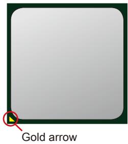
CPU (Central Processing Unit)
Introduction to AM3/AM3+CPU
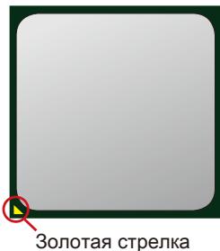
The surface of CPU. Remember to apply some thermal paste on it for better heat dispersion.
Important
Overheating
Overheating can seriously damage the CPU and mainboard. Always make sure the cooling fans work properly to protect the CPU from overheating. Be sure to apply an even layer of thermal paste (or thermal tape) between the CPU and the heatsink to enhance heat dissipation.
Replacing the CPU
When replacing the CPU, always turn off the system's power supply and unplug the power supply's power cord to ensure the safety of the CPU.
Overclocking
This mainboard is designed to support overclocking. Before attempting to overclock, please make sure that all other system components can tolerate overclocking. Any attempt to operate beyond product specifications is not recommend. MSI does not guarantee the damages or risks caused by inadequate operation beyond product specifications.
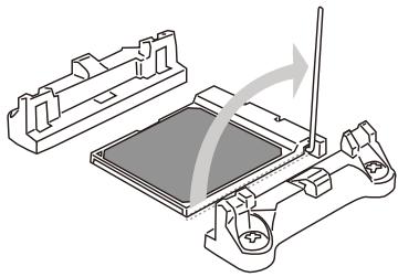
CPU & Cooler Installation
When you are installing the CPU, make sure the CPU has a cooler attached on the top to prevent overheating. Meanwhile, do not forget to apply some thermal paste on CPU before installing the heat sink/cooler fan for better heat dispersion.
Follow the steps below to install the CPU & cooler correctly. Wrong installation will cause the damage of your CPU & mainboard.
-
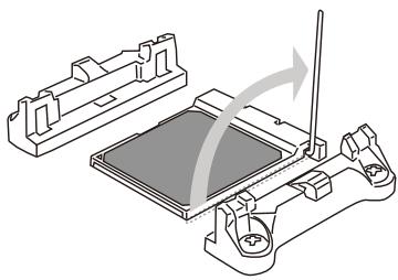
Pull the lever sideways away from the socket. Make sure to raise the lever up to a 90-degree angle.
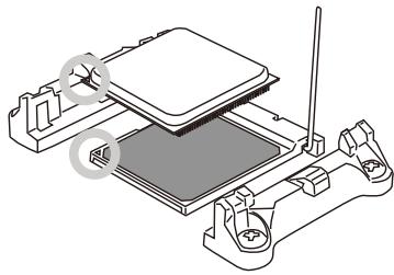
-
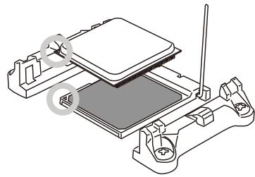
Look for the gold arrow of the CPU. The gold arrow should point as shown in the picture. The CPU can only fit in the correct orientation.
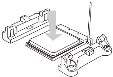
-
If the CPU is correctly installed, the pins should be completely embedded into the socket and can not be seen. Please note that any violation of the correct installation procedures may cause permanent damages to your mainboard.
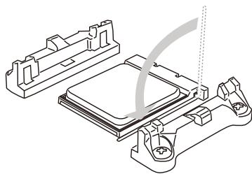
-
Press the CPU down firmly into the socket and close the lever. As the CPU is likely to move while the lever is being closed, always close the lever with your fingers pressing tightly on top of the CPU to make sure the CPU is properly and completely embedded into the socket.
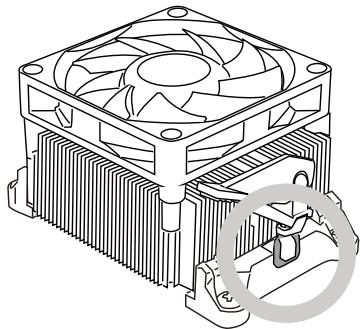
- Position the cooling set onto the retention mechanism.
Hook one end of the clip to hook first.
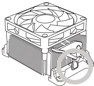
- Fasten down the lever.
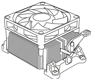
- Then press down the other end of the clip to fasten the cooling set on the top of the retention mechanism.
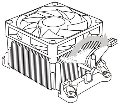
Locate the Fix Lever and lift up it.
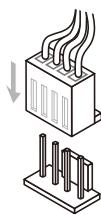
- Attach the CPU Fan cable to the CPU fan connector on the mainboard.
Important
- While disconnecting the Safety Hook from the fixed bolt, it is necessary to keep an eye on your fingers, because once the Safety Hook is disconnected from the fixed bolt, the fixed lever will spring back instantly.
- Confirm that the CPU cooler has formed a tight seal with the CPU before booting your syste.
- Please refer to the documentation in the CPU cooler package for more details about CPU cooler installation.
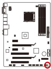
Mounting Screw Holes
When installing the mainboard, first install the necessary mounting stands required for an mainboard on the mounting plate in your computer case. If there is an I/O back plate that came with the computer case, please replace it with the I/O backplate that came with the mainboard package. The I/O backplate should snap easily into the computer case without the need for any screws. Align the mounting plate's mounting stands with the screw holes on the mainboard and secure the mainboard with the screws provided with your computer case. The locations of the screw holes on the mainboard are shown below. For more information, please refer to the manual that came with the computer case.
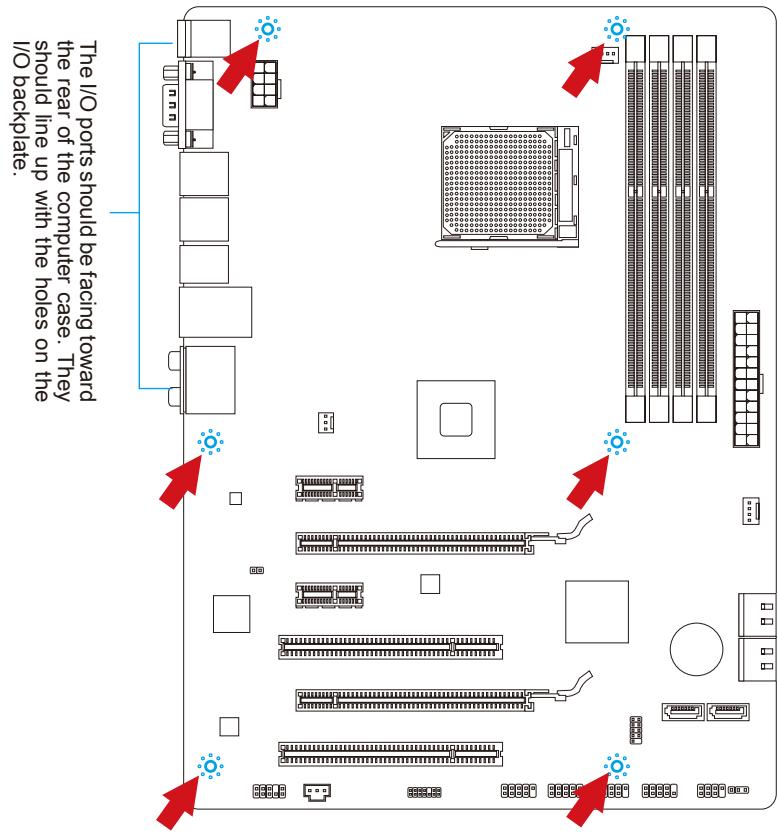
Important
- Install the mainboard on a flat surface free from unnecessary debris.
- To prevent damage to the mainboard, any contact between the mainboard circuitry and the computer case, except for the mounting stands, is prohibited.
- Please make sure there are no loose metal components on the mainboard or within the computer case that may cause a short circuit of the mainboard.
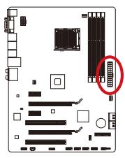
Power Supply
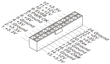
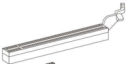
JPWR1:ATX24-pinPowerConnector
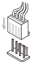
This connector allows you to connect an ATX 24-pin power supply. To connect the ATX 24-pin power supply, align the power supply cable with the connector and firmly press the cable into the connector. If done correctly, the clip on the power cable should be hooked on the mainboard's power connector.
JPWR2:ATX8-pinPowerConnector
This connector provides 12V power to the CPU.
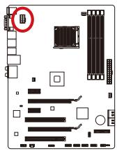
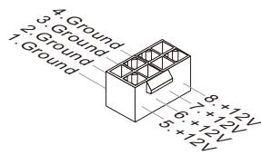
Important
Make sure that all the power cables are securely connected to a proper ATX power supply to ensure stable operation of the mainboard.
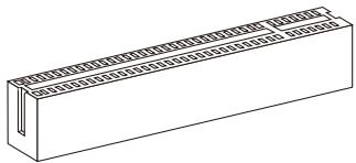
Memory
These DIMM slots are used for installing memory modules. For more information on compatible components, please visit http://www.msi.com/service/test-report
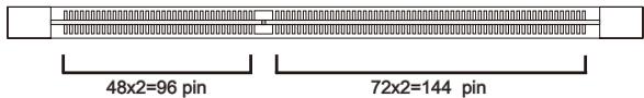
DDR3
240-pin, 1.5V
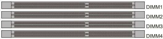
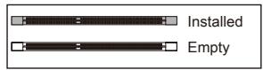
Dual-Channel mode Population Rule
In Dual-Channel mode, the memory modules can transmit and receive data with two data bus channels simultaneously. Enabling Dual-Channel mode can enhance system performance. The following illustrations explain the population rules for Dual-Channel mode.
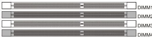
①
②
Important
- DDR3 memory modules are not interchangeable with DDR2, and the DDR3 standard is not backward compatible. Always install DDR3 memory modules in DDR3 DIMM slots.
- In Dual-Channel mode, make sure that you install memory modules of the same type and density in different channel DIMM slots.
- To enable successful system boot-up, always insert the memory modules into the DIMM4/ DIMM2 first.
- Due to chipset resource usage, the system will only detect up to 31+ GB of memory (not full 32 GB) when all DIMM slots have 8GB memory modules installed.
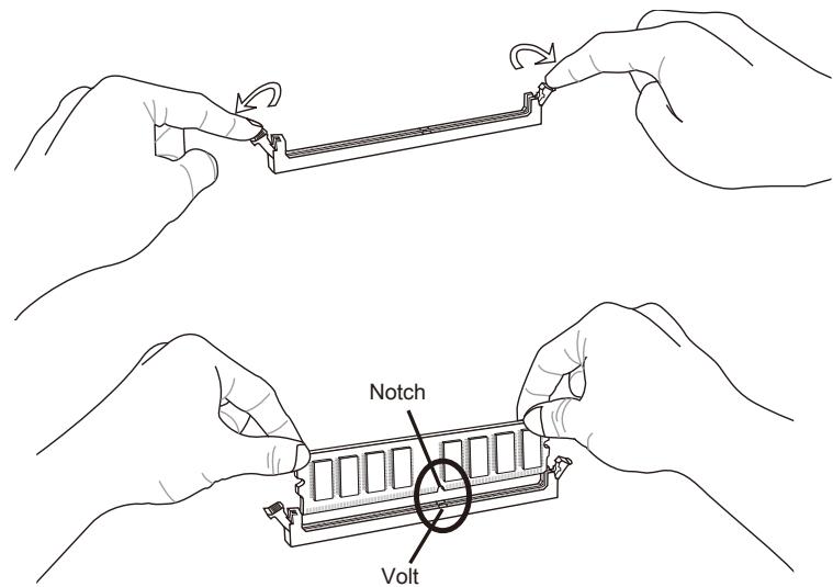
Installing Memory Modules
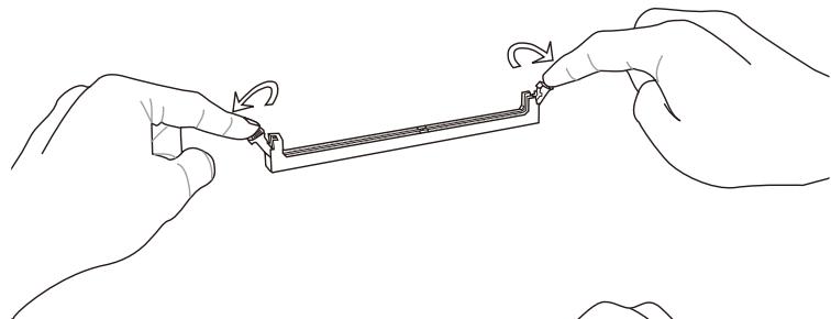
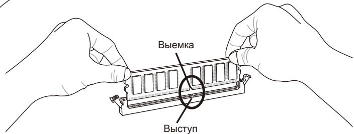
- Unlock the DIMM slot by pushing the mounting clip to the side. Vertically insert the memory module into the DIMM slot. The memory module has an off-center notch on the bottom that will only allow it to fit one way into the DIMM slot.
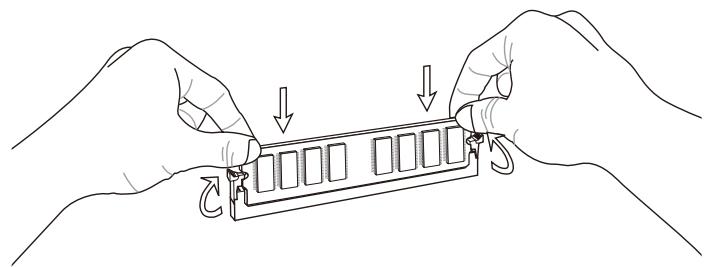
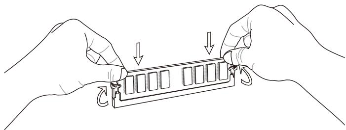
- Push the memory module deep into the DIMM slot. The plastic clip at side of the DIMM slot will automatically close when the memory module is properly seat and an audible click should be heard.
- Manually check if the memory module has been locked in place by the DIMM slot's side clip.
Expansion Slots
This mainboard contains numerous ports for expansion cards, such as discrete graphics or audio cards.
PCIe (Peripheral Component Interconnect Express) Slot
The PCIe slot supports the PCIe interface expansion card.
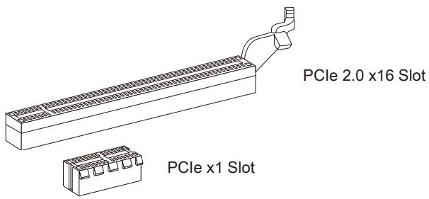
PCI (Peripheral Component Interconnect) Slot
The PCI slot supports additional LAN, SCSI, USB, and other add-on cards that comply with PCI specifications.
32-bit PCI Slot
PCI Interrupt Request Routing
IRQ, or interrupt request lines, are hardware lines over which devices can send interrupt requests to the processor. The PCI IRQ pins are typically connected to the PCI bus pins as followed:
| Order1 | Order2 | Order3 | Order4 | |
| PCI Slot1 | INT E# | INT F# | INT G# | INT H# |
| PCI Slot2 | INT F# | INT G# | INT H# | INT E# |
Important
When adding or removing expansion cards, always turn off the power supply and unplug the power supply power cable from the power outlet. Read the expansion card's documentation to check for any necessary additional hardware or software changes.
Internal Connectors
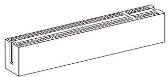
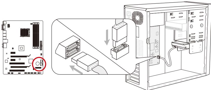
SATA1~6: SATA Connector
This connector is a high-speed SATA interface port. Each connector can connect to one SATA device. SATA devices include disk drives (HDD), solid state drives (SSD), and optical drives (CD/DVD/Blu-Ray).
* The MB layout in this figure is for reference only.
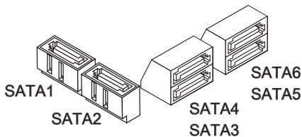
SATA1~6 (6Gb/s, by AMD® SB950)
Important
- Many SATA devices also need a power cable from the power supply. Such devices include disk drives (HDD), solid state drives (SSD), and optical drives (CD / DVD / Blu-Ray). Please refer to the device's manual for further information.
- Many computer cases also require that large SATA devices, such as HDDs, SSDs, and optical drives, be screwed down into the case. Refer to the manual that came with your computer case or your SATA device for further installation instructions.
- Please do not fold the SATA cable at a 90-degree angle. Data loss may result during transmission otherwise.
- SATA cables have identical plugs on either sides of the cable. However, it is recommended that the flat connector be connected to the mainboard for space saving purposes.
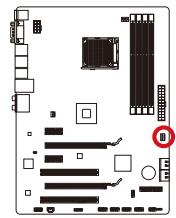
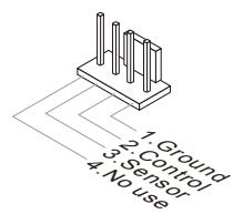
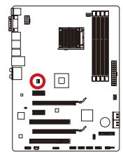
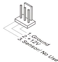
CPUFAN,SYSFAN1~2: Fan Power Connectors
The fan power connectors support system cooling fans with +12V . If the mainboard has a System Hardware Monitor chipset on-board, you must use a specially designed fan with a speed sensor to take advantage of the CPU fan control. Remember to connect all system fans. Some system fans may not connect to the mainboard and will instead connect to the power supply directly. A system fan can be plugged into any available system fan connector.
CPUFAN
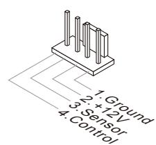
SYSFAN1
SYSFAN2
Important
- Please refer to your processor's official website or consult your vendor to find recommended CPU cooling fans.
- The CPUFAN connectors support Smart Fan Control with liner mode. The Control Center II utility can be installed to automatically control the fan speeds according to the CPU's and system's temperature.
- If there are not enough ports on the mainboard to connect all system fans, adapters are available to connect a fan directly to a power supply.
- Before first boot up, ensure that there are no cables impeding any fan blades.
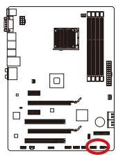
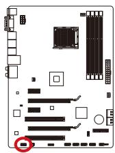
JFP1, JFP2: Front Panel Connectors
These connectors connect to the front panel switches and LEDs. The JFP1 connector is compliant with the Intel® Front Panel I/O Connectivity Design Guide. When installing the front panel connectors, please use the enclosed mConnectors to simplify installation. Plug all the wires from the computer case into the mConnectors and then plug the mConnectors into the mainboard.
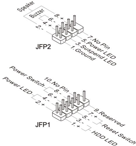
Important
- On the connectors coming from the case, pins marked by small triangles are positive wires. Please use the diagrams above and the writing on the mConnectors to determine correct connector orientation and placement.
- The majority of the computer case's front panel connectors will primarily be plugged into JFP1.
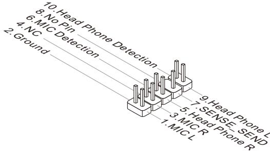
JAUD1: Front Panel Audio Connector
This connector allows you to connect the front audio panel located on your computer case. This connector is compliant with the Intel® Front Panel I/O Connectivity Design Guide.
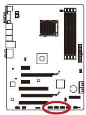
JUSB1~3: USB 2.0 Expansion Connectors
This connector is designed for connecting high-speed USB peripherals such as USB HDDs, digital cameras, MP3 players, printers, modems, and many others.
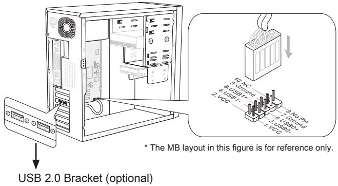
Important
Note that the VCC and GND pins must be connected correctly to avoid possible damage.
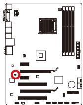
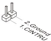
JCI1: Chassis Intrusion Connector
This connector connects to the chassis intrusion switch cable. If the computer case is opened, the chassis intrusion mechanism will be activated. The system will record this intrusion and a warning message will flash on screen. To clear the warning, you must enter the BIOS utility and clear the record.
JTPM1: TPM Module connector
This connector connects to a TPM (Trusted Platform Module). Please refer to the TPM security platform manual for more details and usages.
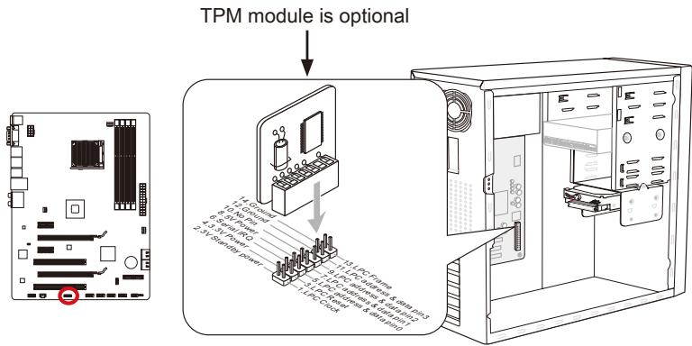
* The MB layout in this figure is for reference only.
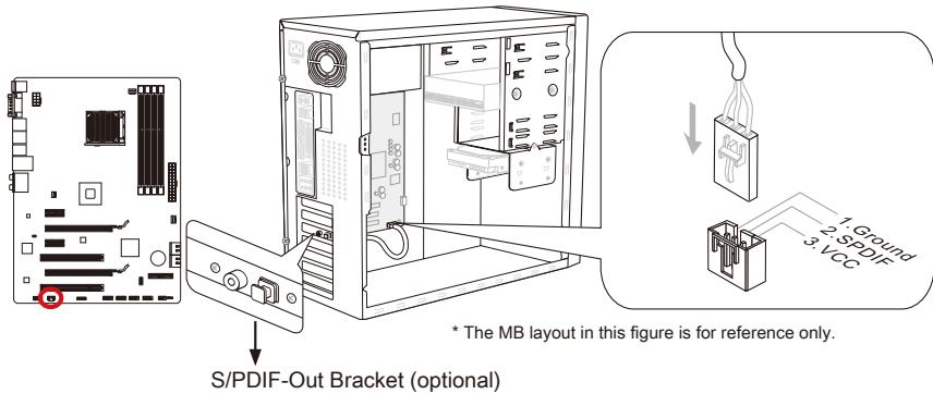
JSP1: S/PDIF-Out Connector
This connector is used to connect S/PDIF (Sony & Philips Digital Interconnect Format) interface for digital audio transmission.
Jumpers
JBAT1: Clear CMOS Jumper
There is CMOS RAM onboard that is external powered from a battery located on the mainboard to save system configuration data. With the CMOS RAM, the system can automatically boot into the operating system (OS) every time it is turned on. If you want to clear the system configuration, set the jumpers to clear the CMOS RAM.

JBAT1

Keep Data

Clear Data
Important
You can clear CMOS by shorting 2-3 pin while the system is off. Then return to 1-2 pin position. Avoid clearing the CMOS while the system is on; it will damage the mainboard.
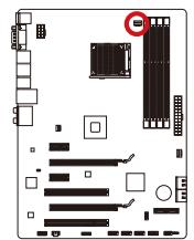
LED Status Indicators
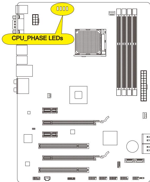
CPU_PHASE LEDs
These LEDs indicate the current CPU power phase mode. Follow the instructions below to read.

Lights

Off
| CPU is in 1 phase power mode. |
| CPU is in 2 phase power mode. |
| CPU is in 3 phase power mode. |
| CPU is in 4 phase power mode. |
BIOS Setup
Click BIOS II is developed by MSI that provides a graphical user interface for setting parameters of BIOS by using the mouse and the keyboard.
With the Click BIOS II, users can change BIOS settings, monitor CPU temperature, select the boot device priority and view system information such as the CPU name, DRAM capacity, the OS version and the BIOS version. Users can import and export parameters data for backup or sharing with friends. After connecting to Internet, users can browse the internet, check mail and live update your system.
Entering
Power on the computer and the system will start POST (Power On Self Test) process. When the message below appears on the screen, press key to enter Setup.
Press DEL key to enter Setup Menu, F11 to enter Boot Menu
If the message disappears before you respond and you still wish to enter Setup, restart the system by turning it OFF and On or pressing the RESET button. You may also restart the system by simultaneously pressing <Ctrl> , <Alt> , and <Delete> keys.
Important
The items under each BIOS category described in this chapter are under continuous update for better system performance. Therefore, the description may be slightly different from the latest BIOS and should be held for reference only.
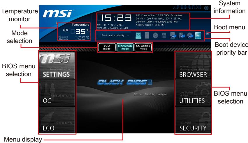
Overview
After entering Click BIOS II, the following screen is displayed.
Important
The pictures in this guide are for reference only and may vary from the product you purchased. Please refer to the actual screens of your system for detailed information.
Temperature monitor
This block shows the temperature of the processor and the mainboard.
System information
This block shows the time, date, CPU name, CPU frequency, DRAM frequency, DRAM capacity and the BIOS version.
BIOS menu selection
These blocks are used to select menus of BIOS. The following options are available:
- SETTINGS - Use this menu to specify your settings for chipset features, boot device.
- OC - This menu contains items of the frequency and voltage adjustments. Increasing the frequency can get better performance, however high frequency and heat can cause instability, we do not recommend general users to overclock.
ECO - This menu is related to energy-saving settings. - BROWSER - This feature is used to enter the MSI Winki web browser.
- UTILITIES - This menu contains utilities for backup and update.
SECURITY - The security menu is used to keep unauthorized people from making any changes to the settings. You can use these security features to protect your system.
Boot device priority bar
You can move the device icons to change the boot priority.
Boot menu
This button is used to open a boot menu. Click the item to boot the system from the device instantly.
Mode selection
This feature allows you to load presets of energy saving or overclocking.
Menu display
This area provides BIOS setting menu that allows you to change parameters.
Boot device priority bar
This bar shows the priority of the boot devices. The light icons indicate that the devices are available.

Click and draw the icon to left or right to specify the boot priority.
Operation
Click BIOS II allows you to control BIOS settings with the mouse and the keyboard. The following table lists and describes the hot keys and the mouse operations.
| Hot key | Mouse | Description |
| <↑↓→←> | Move the cursor | Select Item |
| <Enter> | Click/ Double-click the left button | Select Icon/ Field |
| <Esc> | Click the right button | Jump to the Exit menu or return to the previous from a submenu |
| <++> | Increase the numeric value or make changes | |
| <-> | Decrease the numeric value or make changes | |
| <F1> | General Help | |
| <F4> | CPU Specifications | |
| <F5> | Enter Memory-Z | |
| <F6> | Load optimized defaults | |
| <F10> | Save Change and Reset | |
| <F12> | Save a screenshot to a FAT/FAT32 USB drive |
Sub-Menus
An arrow symbol appears to the left of certain fields that means it contains a sub-menu. A sub-menu contains additional options for a field parameter. You can use arrow keys (↑↓) or mouse to highlight the field and press
General Help
Click BIOS II provides General Help window. You can call up the window from any BIOS menu by simply pressing <F1> or click HELP on BIOS setting screen. The Help window lists the appropriate keys to use and the possible selections for the highlighted item.
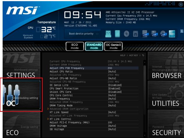
OC Menu
This menu is for advanced users who want to overclock the mainboard.
Important
Overclocking your PC manually is only recommended for advanced users.
- Overclocking is not guaranteed, and if done improperly, can void your warranty or severely damage your hardware.
- If you are unfamiliar with overclocking, we advise you to use OC Genie for easy overclocking.
Current CPU/ DRAM Frequency
These items show the current clocks of CPU and Memory speed. Read-only.
Adjust CPU FSB Frequency
This item is used to adjust the CPU FSB frequency (in MHz).
Adjust CPU Ratio
This item is used to adjust CPU clock multiplier (ratio). It is available only when the processor supports this function.
Adjusted CPU Frequency
It shows the adjusted CPU frequency. Read-only.
Adjust CPU-NB Ratio
This item is used to adjust CPU-NB ratio.
Adjusted CPU-NB Frequency
It shows the adjusted CPU-NB frequency. Read-only.
OC Genie Lite
Setting this item to [Enabled] allows the system to detect the maximum FSB clock and to overclock automatically. If overclocking fails to run, you can try the lower FSB clock for overclocking successfully.
CPU Smart Protection
CPU Smart Protection is a mechanism of CPU overheating protection. It will automatically reduce the clock when the CPU temperature gets too hot.
Unlock CPU Core
This item is used to unlock the CPU core. Please refer to the procedures below for CPU core unlocked in BIOS setup.
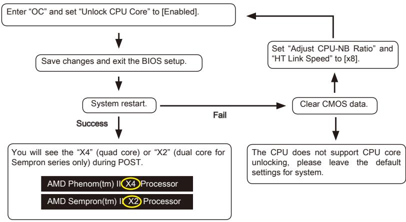
Important
-
This CPU core unlocked behavior depends on the CPU ability/ characteristic, and it is not guaranteed.
-
Depend on CPU's characteristic, once you get instable scenario, please restore the default settings for system.
-
You can also check the core numbers in performance tab of Windows task manager.
CPU Core Control
This item allows you to select the number of active processor cores.
DRAM Frequency
This item allows you to adjust the DRAM frequency. Please note the overclocking behavior is not guaranteed.
Adjusted DRAM Frequency
It shows the adjusted DRAM frequency. Read-only.
DRAM Timing Mode
Select whether DRAM timing is controlled by the SPD (Serial Presence Detect) EEPROM on the DRAM module. Setting to [Auto] enables DRAM timings and the
following "Advanced DRAM Configuration" sub-menu to be determined by BIOS based on the configurations on the SPD. Selecting [Link] or [Unlink] allows users to configure the DRAM timings for each channel and the following related "Advanced DRAM Configuration" sub-menu manually.
Advanced DRAM Configuration
Press
Command Rate
This setting controls the DRAM command rate.
tCL
Controls CAS latency which determines the timing delay (in clock cycles) of starting a read command after receiving data.
tRCD
Determines the timing of the transition from RAS (row address strobe) to CAS (column address strobe). The less clock cycles, the faster the DRAM performance.
tRP
Controls number of cycles for RAS (row address strobe) to be allowed to pre-charge. If insufficient time is allowed for RAS to accumulate before DRAM refresh, the DRAM may fail to retain data. This item applies only when synchronous DRAM is installed in the system.
tRAS
Determines the time RAS (row address strobe) takes to read from and write to memory cell.
tRFC
This setting determines the time RFC takes to read from and write to a memory cell.
tWR
Determines minimum time interval between end of write data burst and the start of a pre-charge command. Allows sense amplifiers to restore data to cell.
tWTR
Determines minimum time interval between the end of write data burst and the start of a column-read command; allows I/O gating to overdrive sense amplifies before read command starts.
tRRD
Specifies the active-to-active delay of different banks.
tRTP
Time interval between a read and a precharge command.
tFAW
This item is used to set the tFAW (four activate window delay) timing.
tWCL
This item is used to set the tWCL (Write CAS Latency) timing.
tCKE
This item is used to set the Pulse Width for DRAM module.
tRTL
This item is used to set Round Trip Latency settings.
tXP
Exit Power Down with DLL on to and valid command; Exit Precharge Power Down with DLL frzon to commands not requiring a locked DLL.
= = Advanced Timing Configuration = =
Follwing items are used to set the read/ write timings for memory.
tRRDR
Read-Read Different Rank, same DIMM.
tRRDD
Read-Read Different Rank.
tWWDR
Write-Write Different Rank, same DIMM.
tWWDD
Write-Write Different Rank.
rWDRDD
Read-Write Different Ranks same or Different DIMM.
tWRDRDD
Write-Read Different Ranks same or Different DIMM.
tRWSR
Read-Write Same Rank.
HT Link Speed
This item allows you to set the Hyper-Transport Link speed. Setting to [Auto], the system will detect the HT link speed automatically.
Adjusted HT Link Frequency
It shows the adjusted HT Link frequency. Read-only.
HT Link Control
Press
HT Incoming/Outgoing Link Width
These items allow you to set the Hyper-Transport Link width. Setting to [Auto], the system will detect the HT link width automatically.
DRAM Voltage/ SB Voltage/ NB Voltage/ CPU Voltage/ CPU-NB Voltage
These items are used to adjust the voltage of CPU, Memory and chipset.
Spread Spectrum
This function reduces the EMI (Electromagnetic Interference) generated by modulating clock generator pulses.
Important
-
If you do not have any EMI problem, leave the setting at [Disabled] for optimal system stability and performance. But if you are plagued by EMI, select the value of Spread Spectrum for EMI reduction.
-
The greater the Spread Spectrum value is, the greater the EMI is reduced, and the system will become less stable. For the most suitable Spread Spectrum value, please consult your local EMI regulation.
- Remember to disable Spread Spectrum if you are overclocking because even a slight jitter can introduce a temporary boost in clock speed which may just cause your synchronized processor to lock up.
Overclocking Profiles
Press
Overclocking Profile 1/2/3/4/5/6
Press
Set Name for Overclocking Profile 1/2/3/4/5/6
Give a name by typing in this item.
Save Overclocking Profile 1/2/3/4/5/6
Save the current overclocking settings to ROM for selected profile.
Load/ Clear Overclocking Profile 1/2/3/4/5/6
Load/ Clear the stored profile settings from ROM.
Overclocking Profile Save
Save the current overlapping settings to USB flash disk.
Overclocking Profile Load
Load the stored settings from USB flash disk.
OC Retry Count
When overclocking has failed, setting this item to [3,5] will allow system to reboot 3/ 5 times with the same overclocked configuration. If overclocking has failed every time, the system will restore the defaults.
CPU Specifications
Press
CPU Technology Support
Press
MEMORY-Z
Press
DIMM1~4 Memory SPD
Press
CPU Features
Press
AMD Cool'n'Quiet
The Cool'n'Quiet technology can effectively and dynamically lower CPU speed and power consumption.
Important
To ensure that Cool'n'Quiet function is activated and will be working properly, it is required to double confirm that:
- Run BIOS Setup, and select Cell Menu. Under Cell Menu, find AMD Cool'n'Quiet, and set this item to "Enabled".
- Enter Windows, and select [Start]->[Settings]->[Control Panel]->[Power Options]. Enter Power Options Properties tag, and select Minimal Power Management under Power schemes.
C1E Support
Enable this item to reduce the CPU power consumption while idle. Not all processors support Enhanced Halt state (C1E).
SVM Mode
This item allows you to enable/disable the AMD SVM (Secure Virtual Machine) Mode.
IOMMU Mode
This item allows you to enable/disable the IOMMU (I/O Memory Management Unit) for I/O virtualization.
Updating the BIOS with Live Update
This section tells you how to update the BIOS by using the Live Update utility before entering Operating System. Live Update will update the BIOS automatically when connecting to the Internet. To update the BIOS with the Live Update utility:
- Click Live Update button installed).

on the BIOS UTILITIES menu. (The Winki must be
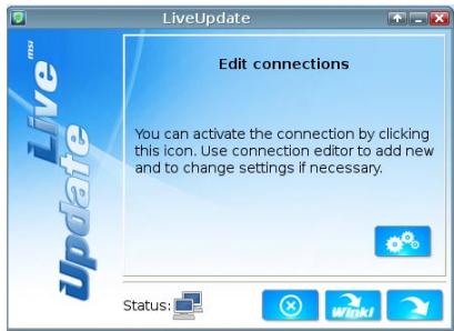
- Setup the connection by click the setting button if necessary.
- Click the next button
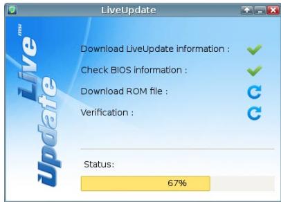
- Live Update will automatically detect the version of BIOS and download the appropriate file.
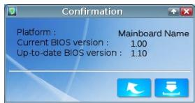
- Click the confirm button to update the BIOS.
Important
Do not update the BIOS if your system is running fine.
Software Information
Take out the Driver/Utility Disc that is included in the mainboard package, and place it into the optical drive. The installation will auto-run, simply click the driver or utility and follow the pop-up screen to complete the installation. The Driver/Utility Disc contains the:
- Driver menu : It provides available drivers. Install the driver by your desire and to activate the device.
- Utility menu : It allows you to install the available software applications.
- Service base menu : Through this menu to link the MSI officially website.
- Product info menu : It shows the newly information of MSI product.
- Security menu : It provides the useful antivirus program.
Important
Please visit the MSI officially website to get the latest drivers and BIOS for better system performance.
Installing Winki
BIOS BROWSER and UTILITIES request Winki, please install the "Winki" software application from MSI Driver Disc in Windows first. And then you can access these two features by clicking their respective buttons.
To install Winki, follow the steps below:
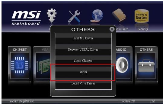
- Power on your computer and enter Windows operating system.
- Insert MSI Driver Disc into the optical drive. The setup screen will automatically appear.
- Click Driver tab.
- Click OTHERS button.
- Select Winki to start installing.
- When finished, restart your computer.

Deutsch
970A-G46/ 970S-G46
Serie
Spezifikationen
Prozessoren
SATA1~6: SATA Anschlüsse
JFP1, JFP2: Frontpanel Anschlüsse
Current CPU/ DRAM Frequency
Adjust CPU FSB Frequency
Adjusted CPU Frequency
Adjusted CPU-NB Frequency
CPU Smart Protection
Adjusted DRAM Frequency
Adjusted HT Link Frequency
HT Incoming/Outgoing Link Width
CPU Technology Support
Emplacement PCIe (Peripheral Component Interconnect Express)
Emplacement PCI (Peripheral Component Interconnect)
Current CPU/ DRAM Frequency
Adjust CPU FSB Frequency
Adjusted CPU Frequency
Adjusted CPU-NB Frequency
Adjusted DRAM Frequency
Adjusted HT Link Frequency
HT Incoming/Outgoing Link Width
▶ Load/ Clear Overclocking Profile 1/2/3/4/5/6
CPU Technology Support
BheuHn BvD npoceccopa AM3/AM3+
TTo6bI yBENHITb TEnIopacceBaHne, yBeINTeCb B TOM, yTO HaneCen CNoi TeNlONpOBOJaSe NaCTbI Ha IpoCeccope.
BHMaHue
IepepeB
IpeperpeM MoKET cepb3HNO NobpeDnTb CEHTpAnbHbN Ipoceccop. Bcerda npOBepaIte paBotoCnOcO6hocTb BeHTnIpyoA, YTO6bl 3aunITb CPU ot npeperpeBa. IyUyuWeHnI TENNoOTBoDa Heo6xOdmo HaneCTn CNoI TENNoPBODAJe NaCTbI (nn TENNoPBODAJe N eHTbI) Mekdy npoeccopom N padatopom.
3aMeHa CPU
Pn3aMeHe CPU, BO n36eXaHne ero noBpeXdHnE, oBraTeIbHo OTKnIOuHTe NCTOCHN KNTaHnI INI BbInBe BUNKy bNoKa NTaNHa I3 pO3eTKN.
Overclocking (Pa3roH)
3Ta cnCTemHna nnata pa3pa6oTana c yuetom Bo3moXhoctn "Pa3roHa" (Overclocking). Tem He Mehee, npa pa3roHe Heo6xOJIMO y6eIHTbcra, qTo nCNoIb3yEmbIe noIb3oBaTeJIeM KOMNHOENTbI NOIDepKINBAIOt HecTaHdapTHbIe napAmetpbI pa6oTbI. Ipon3BOUInTeB He peKoMeHdyet NcNoJIb3oBaTb NapAmetPbI, BblXOJaIe 3a npedeJIb TexHnuecknx XapaKTepNC TkycPoICTB. Ipon3BOUInTeB Tak Jke He rapaHTnpuyET OTCYCTBne IOBpeXdeHn INpyrEpeNCKn, Bbl3BaHHbIe HecTaHdapTHbIMn napAmetpAMN, BblXOJaIzIMN 3a npedeJIb TexHnuecknx XapaKTepNCtIK.
YctaHOBka npoceccopa n BENTNJIArTopa
Bo n36exahanne neperepeba npn pa6ote o6ra3aTeNbHO yCTaHOBIne BENTINJATOP npouecoppa. OndHOBpemehno, YTObI yNyuWHTb TENNOOTBOID, y6eINTecb B TOM, YTO HaHeCen CNoi TEnNoPobOJaUeI NaCTbI Ha npoueccope nepeD yCTaHOBKoB EHTINJATopa.
CneyuTe daHbIM yka3aHnM dIy npabInbHOY cTaHOBKn. HenpaBnBnaYcTaHOBKa npBBeT K NOBpeKdEHHIO pOeCCopa N CNTeMHo INaTbI.
1.ПОДнИМЛТЕВ ВЕРТИКАЛБНОЕNOLOЖЕни рblчжOK,нхоялсьсясбokу pa3bema.
- 06paTInTe BHNMaHne Ha 3oIOnTyO CTpeNky (gold arrow) Ha CPU. OHa DOJIxKHa 6bITb paCnONoXeHa TaK, KaK nOKa3aHo Ha pncyHke. CPU MOxHO BCTaBtB TOnbKO npn erO npabINbHOOpNEHTaUIM.
-
Пп павиьhoи установке CPU erо Контakтbl ПОнсосты BOИутВ разьем, И nx He 6удET BИнHO. ПOMнITE, УTO Лбобе пименени сильп рп установке CPU может Bbl3BaTb cepь�3Hble NOВржденя CBCTeMHои ПпаТы.
-
AkkypaTHo npnKmnte CPU kpa3bemy n onyctnte pbuqakok. Nocoklbky CPU npn onyckaHn pbuqka MoXeT nepemectNbsc, octopoxHo npnxMnte CPU naIbamn B ueHTpe TaK, yTo6bl OH npaBnIbHo n noJIHOCTbIO 3aФNKcnpObaIcR pa3beme.


- Pa3mecntte BENTnIaTOp Ha y3JIe KpennHeN. BNaHane 3aueInTe OIN H erO KpaI.
- 3aФнксуп Te paДиatopдальнeншIM NOBOPOTm pbIyara.

- 3aTeM Haxmnte Ha dpyroK paai, YTObbl yCTaHOBnTB paHaatop Ha y3en KpeIeHn. HauNTe pbuHg fHKcaunn NIOHNMTe ero.

- Пдклочи Кабел В entnilotopa CPU K COOTBETCTByuOeMy pa3bemy cnCTemHoi nlaTbl.
BHMaHue
- Пи отcoeINHEnn ФнксUpyIoIe rpo bIyara Heo6xOДmO co6IIOaTb OCTOPOKHOCtB,Тak кak pIyar noInpnyKInHeN I npn OTnYcKaHN OH BepHETc C INCXODHoe nIOnJoxHne.
- Пара вкючимсстмь убдтесь,чTo поцecspну купр сфорmpoban repmetuhoe ynpIoTHeHne c npoceccopa.
- 3a Долоннельно Иформацей об установке Вентлитopa пюцeccopa, obpatntecь К дokум entaци в уразковке Вentedятopa пюцeccopa.
OTBepCTnI IOy yCTaHOBOUHbIe BnHTbI
UcTaHOBKa MoDyJIe NAmrTn
- Pa36nokpyte DIMM cnot, pa3BeJa 3axmMb b CtopoHb. BCTabTe moynb namrB cnot DIMM BepTkaJIbHo. Ha moyne namrN mMeTc CmeueHHa oT ueHtpa BbIeMaBn3y, 6laorOapar KOTopoJ erO MOxHO BCTaBtB rHe3do DIMM TolbKO onpeJeHHbIM o6pa3OM.
- Bctabte moynb namrtnB cnot DIMM do ynopa. Pnp npabnboh outaHOBKe MOyI, pnaCTNKOBbIe 3bIKMbI C o6oNx CTOpOH OT cNoTa, abTomaTHueckn 3aKPOHTcX apaKaTepHbIM ueJYKOM.
- BpyuHny u6eHntecb, yTO MOyIb 3aKpeJIeH B cIoTe DIMM 3aUeJIko Co CToPOhbl 3axkIMa.
CLOTbI paCUnpeHnA
Данная Материнckая плanta соржпн.T HeCKoJIbKO CnotOB ДЯ ПЛaТ рacширеня, TAKIN KAKДИСКрт themselves BndeO n aydno KapTbI.
Cnot PCIe (Peripheral Component Interconnect Express)
CnotPCIe noDaepxnBaet KapTb paacnepenHn INTepeeaPCIe.
PCIe x1 cnot
PCIe 2.0 x16 cnot
Cnot PCI (Peripheral Component Interconnect)
Cnot PCI no3Bnonraet yctaHOBnTB kapTb LAN, SCSI, USB and pyrne dononHntelhble KapTb paacunpeHnA, KOtOpbIE COOTBeTCTByOT cneuФнkaun PCI.
32-bitPCIcnot
MapuTn3aun 3anpocOB npepbHaHg PCI
IRQ, INI ININIA 3anpoca npepbIBaHNA, annapaTHa ININRA, NO KOTOPo yCTpoiCTBa MOryT nocblnabT 3anpocbl npepbIBaHNA npoeCEcCPOy. CtaHdapTHoe NODKIIIOueHne PCI IRQ K KOHTAKTAM IINBI PCI nokaHO HNKe:
| Порадok1Порадok2Порадok3Порадok4 | ||||
| PCI сnot1 | INT E# | INT F# | INT G# | INT H# |
| PCI сnot2 | INT F# | INT G# | INT H# | INT E# |
BhimaHine
Pn do6ablennn nnn n3Bneeyenn nnat paccnpehna Bcerda BbkiyauaTe ntaHne n BbHMaIte shyp nntanry n3 po3eKn. IpouTne dokymentauuHa KapTy paacnpehny n BbINONHtE Heo6xOumblte annapaTHBe nnnporpamMbIe yctahOBKn dJa daHHo n PnAbl, TaKne kak nepeMbUcKn, nepeKluoyateNn nn konphiunpyaquio BIOS.
Pa3beMbl
SATA1~6:Pa3beM SATA
Current CPU/ DRAM Frequency
3TN nyHKbI noka3bIbaHOT TekyuH Yo cactOty CPU u ckopocb naMRTN. TOnbKO dIyUTeHEN.
Adjust CPU FSB Frequency
3TOT nyHKT nCNoJIb3yETcI dIpeRnIpOBaHmY cactoTbCPU FSB (B MfU).
Adjust CPU Ratio
3TOT nyHKT nCnoJIb3yETcI dIe peryIINPOBKN MHOXITeIg npOceccopa (ratio). OH DOCTyIeH ToJIbKO ToIgA, KOrIa npOceCCOP NoIepKInBaE TTy FyHKUIO.
Adjusted CPU Frequency
3TOT nyHKT noka3bIaET Tekyu yu cactoty CPU. TOnIbKO dnyTeHnA.
Adjust CPU-NB Ratio
3TOT nyHKT nCnObl3yETcI dIaI pErIInpOBK uactOtBt CPU-NB.
Adjusted CPU-NB Frequency
3TOT nyHKT noka3bIbaET TeKuIyU yactOty CPU-NB. TOnIbKO dIyTeHnIa.
OC Genie Lite
YctaHOBka 3Toro nyHKta B [Enabled] no3BONJrE CTeMe onpeJeJIaMbMyu YactOToy FSB n pa3roH aBTOMaTHueckn. Ecnn pa3roH He ydaIcra, Bam MOxHO yMeHbIHTb TaKTOByo YactOToy FSB drr pa3roHa ydaHNo.
CPU Smart Protection
CPU Smart Protection, 3to obopydobAHne npedeoxpahenHn neperpeBa CPU. Oho ABTomatueckn cokpaTNT TaKToBvU qaToTy pn npeperpeBe temnpaTpyb CPU.
Unlock CPU Core
ТOTpyнгИсноьуетсдпяразькINРOBКCPUcore.ClenyTe yka3aHnЯm HnKeДпяразькINPobK CPU core unlockedВ国有资产BIOS.
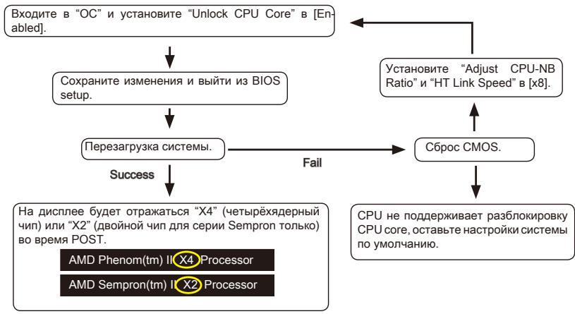
BHMHHE
-Данhoe DeиCTBne pa3bNoKIpOBKn CPU core 3aBucnt OTo cnoc6hoctn/xapakTepcntIKOB CPU n He rapaHTnpyeTc.
B 3aBncmocn OT xapaKTepeNtKOB CPU, KOrda nOraBJIeTc HecTa6bIbHa cnTuaIy, noXaIyICTa, BOCCTaHOBInTe HAcTpoIKN CnCTeMbI NO yMOJUHIO.
- Bam MOKHO TAKKE npOBepuTB KOJNUeCTBO YUNCeTob B cToJIbSe BbICTpoJeCTBVe DnCneTepa 3aau Windows.
CPU Core Control
3TOT nyHKT NcIOnJIb3YeTeC dIЯ BbIbOpa KOnIuYeCTBa AKTNBbIx YInCeTOB pOueCCopoB.
DRAM Frequency
3TOT nyHKT nCIOJIb3yeTcI dIy HAcTPOIKN yacToTbI DRAM. O6paTnTe BHMaHne Ha To, YTO ycNEuHocTb pa3roHa He rapaHTnpyeTcI.
Adjusted DRAM Frequency
3TOT nyHKT noka3bIbaeTe TKyUyU qactOty DRAM. TOnIbKO dIra YTeHnA.
DRAM Timing Mode
OnpeJeIeT 6yUr Iu TaMmHrN DRAM KOHTpOIpoBaTbc DaHbIMn n3 SPD (Serial Presence Detect) EEPROM ha moDyIe DRAM. Ppr BbIbope 3NaueHnra [Auto] taMmHrN
DRAM, BkIIOUa IyHKbI MeHIO, IpeueHCNEHHbIe HNKe, yCTaHaBJIbAHTcB BIOS B COOTBeTCTBm C daHbIMn n3 SPD. YcTaHOBaK3NaueHnB [Link] uIN [Unlink] no3BOJrE TByuHyO peYIpOBAt TaMmHn DRAM DoCTynHbIe B 3tOM MeHIO I nepeXoDITb B noDMHeIO «Advanced DRAM Configuration» («PacuIPeHHa KOnΦmrgpauZn DRAM»).
Advanced DRAM Configuration
HaxmTe
Command Rate
Даннаянachtpoиka onpeдяет ckopoctb BblnoJIHHeNЯ KMaH DRAM.
tCL
Adjusted HT Link Frequency
3TOT nyHKT nokaBbAeT TaKToByo YacToTy uINHbI HT. TOnbKO IaYteHnA.
HT Link Control
HaxmTe
HT Incoming/Outgoing Link Width
3TOT nyHKT onpeJeIeT uINHy BXOJaIe/NcXOJaIeJIuHn HT. Ipn yCTaHOBKe B [Auto], cNCTema abTomatUneckn onpeJeIeT uINHy uINHbI HT.
DRAM Voltage/ SB Voltage/ NB Voltage/ CPU Voltage/ CPU-NB Voltage
3Tn nykkbI no3BOJIAOT perylnopobat hnapxkeHne CPU, namrtn, n uinceta.
Spread Spectrum
3TaФункцисн��аET EMI (Electromagnetic Interference), reHepinpoBAn MOnyJIaCnei nyIbcoB TAKTOBORO reHepaTopa.
Bhimahine
- Ecnn y Bac Het npo6nem c nomexamn, octabte 3naeHne [Disabled] (3anpeucho) Дялушew CTaBnIbHOCTn n pOun3BOUnteNbHOCTn. Ondako, ecnn y Bac BO3HnKaIOT 3NeKtpomarHHTbIe nomexn, Bbl6epnte Spread Spectrum dans nx yMeHbSeHnra.
-ЧмбльшеЗачениSpreadSpectrum,temнижебудетуровьзлкгомагHTbIXnomex,Ho cntema ctaHet Mehee ctabnblhoI.ДЯВБОРапoxODяцeroЗачениSpreadSpectrum,Cbepbtecbco3haeHnMmурбийЗлкгомагHTbIXnomex,yctahOBNeHHbix3aKOHDAteJIbCTBOM. - He 3abyIte 3anpeTntb nCnObnzOBaHne yHKnUu Spred Spectrum, ecnn Bbl "pa3roHaeTe" CnCTeMHny PnATy. 3To Heo6xOIMo, TAK KAc daxe He6oBbou Jpe6e3r CnHAnOB TaKTOBOrO rHePeTaOpA MoKe TpNBeCTN K OTKa3y "pa3orHaHHoro" npoecoppa.
Overclocking Profiles
Haxmnte
Overclocking Profile 1/2/3/4/5/6
Haxmnte
Set Name for Overclocking Profile 1/2/3/4/5/6
YkaKInTe NmB 3TOM nOJIe.
Save Overclocking Profile 1/2/3/4/5/6
CoxpaHnTe TeKyuIe HacTpoI K pa3roHa IaIy BbIbpaHOrO npoPnIa Ha I3Y.
Load/ Clear Overclocking Profile 1/2/3/4/5/6
CoxpanenHe/ydaIeHne hAcTpoek npoФnJIra3rOHa Ha I3Y.
Overclocking Profile Save
CoxpaHHeNtKyuIxN HacTpoEk pa3roHa Ha 1neu-dnck USB.
Overclocking Profile Load
3arpy3ka coxaHennbIX HacTpoE K cIneu-dncka USB.
OC Retry Count
Pn HeydaHOM pa3rohe, yCTaHOBka 3Toro nykTa B 3/5 no3BOJrae CnCTeMe nonbItacBc 3arpy3ntbcg 3/5 pa3a c 3adAHNO konfumrgpauee. Ecn 3arpy3ntbcg He ydaJaactbcg BCE TpN pa3a, CNCTema BOCCTaHOBt HACTpOKn nO yMOJuaHHIO.
CPU Specifications
Haxmte
TolbkoДЯУтEHЯ.ДЯпрсмOTраэТоиИнфорmaцинХakmITEHa[F4].
CPU Technology Support
Haxmnte