
NF725-C35 - Motherboard MSI - Free user manual and instructions
Find the device manual for free NF725-C35 MSI in PDF.
| Product Type | ATX Motherboard |
| Brand | MSI |
| Model | NF725-C35 |
| Form Factor | ATX (30.5 cm × 19.0 cm) |
| Chipset | NVIDIA GeForce 7025 / nForce 630a |
| Processor Socket | AM3 |
| Supported Processors | AMD Phenom II, Phenom, Athlon II, Athlon, Sempron |
| Supported Memory | 2x DDR3 DIMM, max 8 GB, DDR3 1600/1066/800 |
| Integrated Audio | Realtek ALC887, 7.1 channels |
| Network | Realtek RTL8111E Gigabit Ethernet |
| Storage Connectors | 2x SATA 3 Gb/s |
| Rear USB Ports | 6x USB 2.0 |
| Internal USB Connectors | 2x USB 2.0 (4 additional ports) |
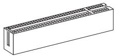
| Expansion Slots | 1x PCIe x16, 1x PCIe x1, 4x PCI |
| Required Power | 24-pin ATX connector + 8-pin ATX 12V connector |
| BIOS | AMI BIOS, graphical interface |
| Maintenance and Cleaning | Dust with a soft, dry cloth. Avoid any liquid. |
| Safety | Unplug before any handling. Discharge static electricity. |
| Spare Parts and Repairability | Processor, memory, expansion card replaceable. Motherboard not repairable. |
Frequently Asked Questions - NF725-C35 MSI
User questions about NF725-C35 MSI
0 question about this device. Answer the ones you know or ask your own.
Ask a new question about this device
Download the instructions for your Motherboard in PDF format for free! Find your manual NF725-C35 - MSI and take your electronic device back in hand. On this page are published all the documents necessary for the use of your device. NF725-C35 by MSI.
USER MANUAL NF725-C35 MSI
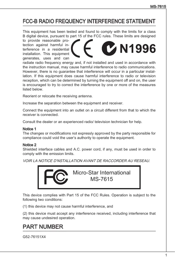
FCC-B RADIO FREQUENCY INTERFERENCE STATEMENT
This equipment has been tested and found to comply with the limits for a class B digital device, pursuant to part 15 of the FCC rules. These limits are designed
to provide reasonable protection against harmful interference in a residential installation. This equipment generates, uses and can


N1996
radiate radio frequency energy and, if not installed and used in accordance with the instruction manual, may cause harmful interference to radio communications. However, there is no guarantee that interference will occur in a particular installation. If this equipment does cause harmful interference to radio or television reception, which can be determined by turning the equipment off and on, the user is encouraged to try to correct the interference by one or more of the measures listed below.
Reorient or relocate the receiving antenna.
Increase the separation between the equipment and receiver.
Connect the equipment into an outlet on a circuit different from that to which the receiver is connected.
Consult the dealer or an experienced radio/ television technician for help.
Notice 1
The changes or modifications not expressly approved by the party responsible for compliance could void the user's authority to operate the equipment.
Notice 2
Shielded interface cables and A.C. power cord, if any, must be used in order to comply with the emission limits.
VOIR LA NOTICE D'INSTALLATION AVANT DE RACCORDER AU RESEAU.

Micro-Star International MS-7615
This device complies with Part 15 of the FCC Rules. Operation is subject to the following two conditions:
(1) this device may not cause harmful interference, and
(2) this device must accept any interference received, including interference that may cause undesired operation.
PART NUMBER
G52-76151X4
COPYRIGHT NOTICE
The material in this document is the intellectual property of MICRO-STAR INTERNATIONAL. We take every care in the preparation of this document, but no guarantee is given as to the correctness of its contents. Our products are under continual improvement and we reserve the right to make changes without notice.
TRADEMARKS
All trademarks are the properties of their respective owners.
MSI is registered trademark of Micro-Star Int'l Co., Ltd.
NVIDIA® is registered trademark of NVIDIA Corporation.
ATI® is registered trademark of ATI Technologies, Inc.
AMD is registered trademarks of AMD Corporation.
Intel is registered trademarks of Intel Corporation.
Windows® is registered trademarks of Microsoft Corporation.
AMI is registered trademark of American Megatrends Inc.
Award® is a registered trademark of Phoenix Technologies Ltd.
Sound Blaster® is registered trademark of Creative Technology Ltd.
Realtek® is registered trademark of Realtek Semiconductor Corporation.
■ JMicron® is registered trademark of JMicron Technology Corporation.
Netware is a registered trademark of Novell, Inc.
REVISION HISTORY
| Revision | Revision History | Date |
| V2.0 | First release for PCB 2.X | September 2010 |
SAFETY INSTRUCTIONS
Always read the safety instructions carefully.
- Keep this User Manual for future reference.
- Keep this equipment away from humidity.
Lay this equipment on a reliable flat surface before setting it up.
- The openings on the enclosure are for air convection hence protects the equipment from overheating. Do not cover the openings.
- Make sure the voltage of the power source is at 110/220V before connecting the equipment to the power inlet.
- Place the power cord such a way that people can not step on it. Do not place anything over the power cord.
Always Unplug the Power Cord before inserting any add-on card or module.
All cautions and warnings on the equipment should be noted.
- Never pour any liquid into the opening that can cause damage or cause electrical shock.
If any of the following situations arises, get the equipment checked by a service personnel:
The power cord or plug is damaged.
Liquid has penetrated into the equipment.
The equipment has been exposed to moisture.
The equipment does not work well or you can not get it work according to User Manual.
The equipment has been dropped and damaged.
The equipment has obvious sign of breakage.
- Do not leave this equipment in an environment above 60^ (140^) , it may damage the equipment.
CAUTION
There is a risk of explosion, if battery is incorrectly replaced. Replace only with the same or equivalent type recommended by the manufacturer.
警告使用者
For better environmental protection, waste batteries should be collected separately for recycling or special disposal.
ENGLISH
To protect the global environment and as an environmentalist, MSI must remind you that...
Under the European Union ("EU") Directive on Waste Electrical and Electronic Equipment, Directive 2002/96/EC, which takes effect on August 13, 2005, products of "electrical and electronic equipment" cannot be discarded as municipal wastes anymore and manufacturers of covered electronic equipment will be obligated to take


back such products at the end of their useful life. MSI will comply with the product take back requirements at the end of life of MSI-branded products that are sold into the EU. You can return these products to local collection points.
DEUTSCH
Thank you for choosing the NF725-C35/ NF725-C21 series (MS-7615 v2.x) ATX mainboard. The NF725-C35/ NF725-C21 series is design based on NVIDIA® GeForce 7025/nForce 630a chipset for optimal system efficiency. Designed to fit the advanced AMD® AM3 processor, the NF725-C35/ NF725-C21 series deliver a high performance and professional desktop platform solution.
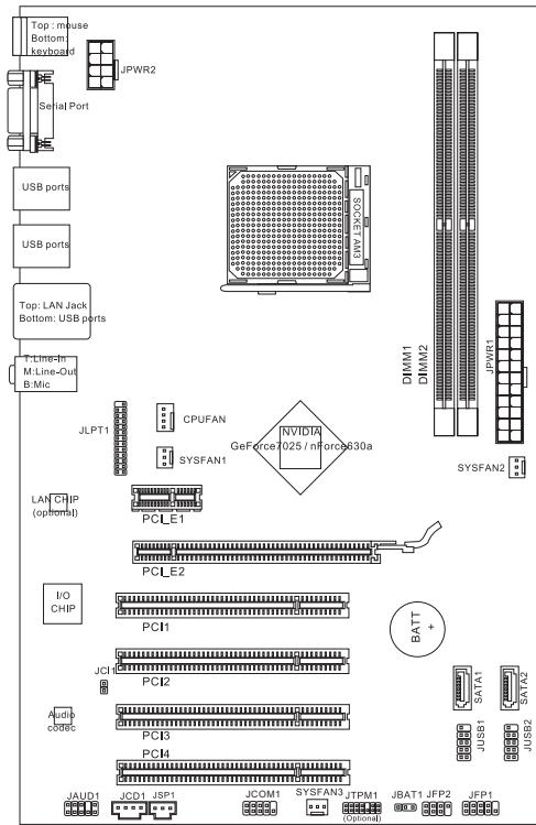
Layout
SPECIFICATIONS
Processor Support
Supports AMD PhenomTM II, PhenomTM, AthlonTM II, AthlonTM and SempronTM processors in AM3 package (For the latest information about CPU, please visit http://www.msi.com/index.php?func=cpuform2)
HyperTransport
Hyper Transport 2.0 supports speed up to 1GHz
Chipset
NVIDIA® GeForce7025 / nForce630a chipset
Memory Support
DDR3 1600/ 1066/ 800 SDRAM (total Max. 8GB)
- 2 DDR3 DIMMs (240pin/ 1.5V)
* (For more information on compatible components, please visit http://www.msi.com/index.php?func=testreport)
LAN
Supports LAN 10/ 100/ 1000 Fast Ethernet by Realtek® RTL8111E (for NF725-C35)
Supports LAN 10/ 100 Fast Ethernet by Realtek® RTL8105E (for NF725-C21)
Audio
Chip integrated by Realtek ALC887
Supports 7.1 channels audio out
Compliant with Azalia 1.0 Spec
SATA
2 SATA 3Gb/s ports
Connectors
Back panel
-1PS/2 mouse port
- 1 PS/2 keyboard port
-1 Serial port
- 6 USB 2.0 ports
- 1 LAN jack
- 3 flexible audio jacks
-
On-Board Connectors
-
2 USB 2.0 connectors
- 1 Chassis Intrusion connector
- 1 CD-In connector
- 1 S/PDIF-Out connector
- 1 Front Panel Audio connector
- 1 TPM connector (optional)
- 1 Serial Port connector
- 1 Parallel Port connector
- 1 CPU Fan Power connector
- 2 System Fan Power connectors
Slots
1 PCIE x16 slot
1 PCIE x1 slot
4 PCI slots, support 3.3V/5V PCI bus Interface
Form Factor
ATX (30.5cm× 19.0cm)
Mounting
6 mounting holes
If you need to purchase accessories and request the part numbers, you could search the product web page and find details on our web address below http://www.msi.com/index.php
SCREW HOLES
When you install the mainboard, you have to place the mainboard into the chassis in the correct direction. The locations of screws holes on the mainboard are shown as below.
The side has to toward the rear, the position for the I/O shield of the chassis.
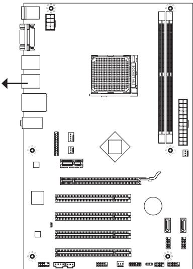


Screw holes
Refer above picture to install standoffs in the appropriate locations on chassis and then screw through the mainboard screw holes into the standoffs.
IMPORTANT
- To prevent damage to the mainboard, any contact between the mainboard circuit and chassis or unnecessary standoffs mounted on the chassis is prohibited.
- Please make sure there are no metal components placed on the mainboard or within the chassis that may cause short circuit of the mainboard.
REAR PANEL
The rear panel provides the following connectors:
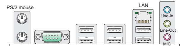
PS/2 keyboard
Serial port
USB ports
USB ports
USB ports
HARDWARE SETUP
This chapter provides you with the information about hardware setup procedures. While doing the installation, be careful in holding the components and follow the installation procedures. For some components, if you install in the wrong orientation, the components will not work properly. Use a grounded wrist strap before handling computer components. Static electricity may damage the components.
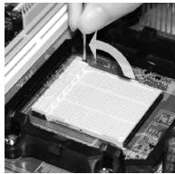
CPU & cooler Installation for AM3
When you are installing the CPU, make sure the CPU has a cooler attached on the top to prevent overheating. Meanwhile, do not forget to apply some thermal paste on CPU before installing the heat sink/cooler fan for better heat dispersion.
Follow the steps below to install the CPU & cooler correctly. Wrong installation will cause the damage of your CPU & mainboard.
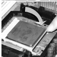
- Pull the lever sideways away from the socket. Make sure to raise the lever up to a 90-degree angle.
- Look for the gold arrow of the CPU. The gold arrow should point as shown in the picture. The CPU can only fit in the correct orientation.
- If the CPU is correctly installed, the pins should be completely embedded into the socket and can not be seen. Please note that any violation of the correct installation procedures may cause permanent damages to your mainboard.
- Press the CPU down firmly into the socket and close the lever. As the CPU is likely to move while the lever is being closed, always close the lever with your fingers pressing tightly on top of the CPU to make sure the CPU is properly and completely embedded into the socket.
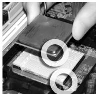
- Position the cooling set onto the retention mechanism. Hook one end of the clip to hook first.
- Then press down the other end of the clip to fasten the cooling set on the top of the retention mechanism. Locate the Fix Lever and lift up it.
- Fasten down the lever.
- Attach the CPU Fan cable to the CPU fan connector on the mainboard.
IMPORTANT
- Mainboard photos shown in this section are for demonstration only. The appearance of your mainboard may vary depending on the model you purchase.
- While disconnecting the Safety Hook from the fixed bolt, it is necessary to keep an eye on your fingers, because once the Safety Hook is disconnected from the fixed bolt, the fixed lever will spring back instantly.
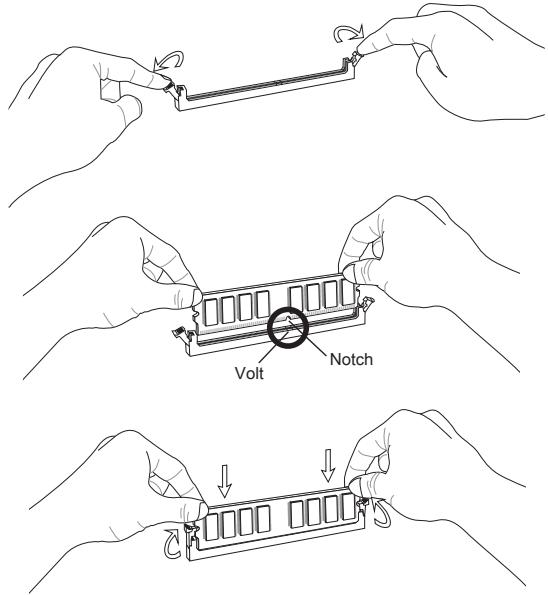
Installing Memory Modules
- The memory module has only one notch on the center and will only fit in the right orientation.
- Insert the memory module vertically into the DIMM slot. Then push it in until the golden finger on the memory module is deeply inserted in the DIMM slot. You can barely see the golden finger if the memory module is properly inserted in the DIMM slot.
- The plastic clip at each side of the DIMM slot will automatically close.
IMPORTANT
- DDR3 memory modules are not interchangeable with DDR2 and the DDR3 standard is not backwards compatible. You should always install DDR3 memory modules in the DDR3 DIMM slots.
- In Dual-Channel mode, make sure that you install memory modules of the same type and density in different channel DIMM slots.
- To enable successful system boot-up, always insert the memory modules into the DIMM1 first.
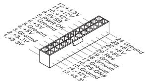
ATX 24-Pin Power Connector: JPWR1
This connector allows you to connect an ATX 24-pin power supply. To connect the ATX 24-pin power supply, make sure the plug of the power supply is inserted in the proper orientation and the pins are aligned. Then push down the power supply firmly into the connector.
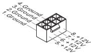
ATX 8-Pin Power Connector: JPWR2
This 12V power connector is used to provide power to the CPU.
IMPORTANT
Make sure that all the connectors are connected to proper ATX power supplies to ensure stable operation of the mainboard.
Serial ATA Connector: SATA1/2
This connector is a high-speed Serial ATA interface port. Each connector can connect to one Serial ATA device.

IMPORTANT
Please do not fold the Serial ATA cable into 90-degree angle. Otherwise, data loss may occur during transmission.
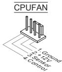
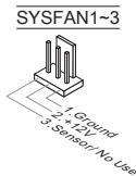
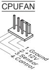
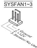
Fan Power Connectors: CPUFAN, SYSFAN1~3
The fan power connectors support system cooling fan with +12V . When connecting the wire to the connectors, always note that the red wire is the positive and should be connected to the +12V ; the black wire is Ground and should be connected to GND. If the mainboard has a System Hardware Monitor chipset onboard, you must use a specially designed fan with speed sensor to take advantage of the CPU fan control.
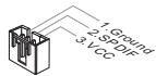
S/PDIF-Out Connector: JSP1
This connector is used to connect S/PDIF (Sony & Philips Digital Interconnect Format) interface for digital audio transmission.

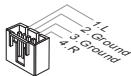
CD-In Connector: JCD1
This connector is provided for external audio input.
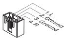
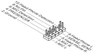
Front Panel Audio Connector: JAUD1
This connector allows you to connect the front panel audio and is compliant with Intel® Front Panel I/O Connectivity Design Guide.
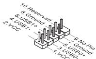
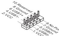
Front USB Connector: JUSB1/ JUSB2
This connector, compliant with Intel® I/O Connectivity Design Guide, is ideal for connecting high-speed USB interface peripherals such as USB HDD, digital cameras, MP3 players, printers, modems and the like.
TPM Module Connector: JTPM1 (optional)
This connector connects to a TPM (Trusted Platform Module) module. Please refer to the TPM security platform manual for more details and usages.
Chassis Intrusion Connector: JCI1
This connector connects to the chassis intrusion switch cable. If the chassis is opened, the chassis intrusion mechanism will be activated. The system will record this status and show a warning message on the screen. To clear the warning, you must enter the BIOS utility and clear the record.
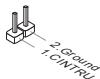
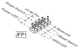
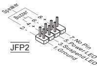
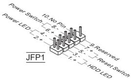
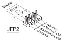
Front Panel Connectors: JFP1, JFP2
These connectors are for electrical connection to the front panel switches and LEDs. The JFP1 is compliant with Intel® Front Panel I/O Connectivity Design Guide.
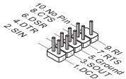
Serial Port Connector: JCOM1
This connector is a 16550A high speed communication port that sends/receives 16 bytes FIFOs. You can attach a serial device.
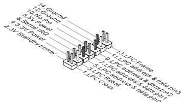
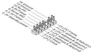
Parallel Port Connector: JLPT1
This connector is used to connect an optional parallel port bracket. The parallel port is a standard printer port that supports Enhanced Parallel Port (EPP) and Extended Capabilities Parallel Port (ECP) mode.

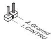
Clear CMOS Jumper: JBAT1
There is a CMOS RAM onboard that has a power supply from an external battery to keep the data of system configuration. With the CMOS RAM, the system can automatically boot OS every time it is turned on. If you want to clear the system configuration, set the jumper to clear data.


Keep Data

Clear Data
IMPORTANT
You can clear CMOS by shorting 2-3 pin while the system is off. Then return to 1-2 pin position. Avoid clearing the CMOS while the system is on; it will damage the mainboard.
PCI Express Slot
The PCI Express slot supports the PCI Express interface expansion card.
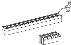
The PCIE x16 slot
The PCIE x1 slot
PCI Slot
The PCI slot supports LAN card, SCSI card, USB card, and other add-on cards that comply with PCI specifications.
IMPORTANT
Make sure that you unplug the power supply first. Meanwhile, read the documentation for the expansion card to configure any necessary hardware or software settings for the expansion card, such as jumpers, switches or BIOS configuration.
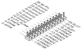
PCI Interrupt Request Routing
When adding or removing expansion cards, make the IRQ, acronym of interrupt request line and pronounced I-R-Q, are hardware lines over which devices can send interrupt signals to the microprocessor. The PCI IRQ pins are typically connected to the PCI bus pins as follows:
| Order Slot | 1 | 2 | 3 | 4 |
| PCI 1 | C# | D# | A# | B# |
| PCI 2 | B# | C# | D# | A# |
| PCI 3 | A# | B# | C# | D# |
| PCI 4 | D# | A# | B# | C# |
BIOS SETUP
Power on the computer and the system will start POST (Power On Self Test) process. When the message below appears on the screen, press key to enter Setup.
Press DEL to enter SETUP
If the message disappears before you respond and you still wish to enter Setup, restart the system by turning it OFF and On or pressing the RESET button. You may also restart the system by simultaneously pressing
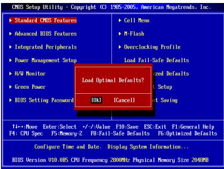
Main Page
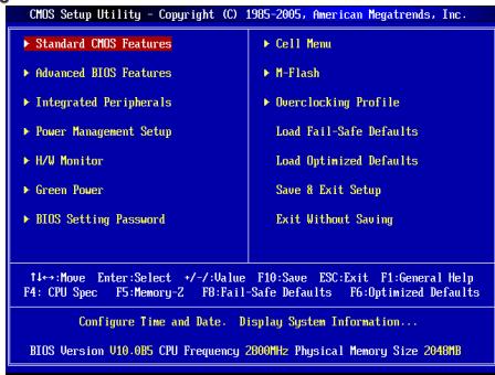
Standard CMOS Features
Use this menu for basic system configurations, such as time, date etc.
Advanced BIOS Features
Use this menu to setup the items of special enhanced features.
Integrated Peripherals
Use this menu to specify your settings for integrated peripherals.
Power Management Setup
Use this menu to specify your settings for power management.
H/W Monitor
This entry shows the status of your CPU, fan, warning for overall system status.
Green Power
Use this menu to specify the power phase.
BIOS Setting Password
Use this menu to set BIOS setting Password.
Cell Menu
Use this menu to specify your settings for frequency/voltage control.
M-Flash
Use this menu to read/ flash (or backup) the BIOS from (to) storage drive (FAT/FAT32 format only).
Overclocking Profile
Use this menu to save/ load your settings to/ from CMOS for BIOS.
Load Fail-Safe Defaults
Use this menu to load the BIOS default values that are factory settings for system operations.
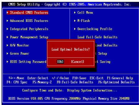
Load Optimized Defaults
Use this menu to load factory default settings into the BIOS for stable system performance operations.
Save & Exit Setup
Save changes to CMOS and exit setup.
Exit Without Saving
Abandon all changes and exit setup.
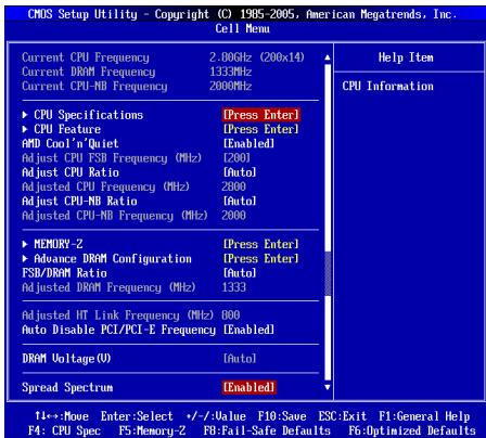
Cell Menu
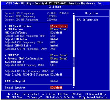
Current CPU/ DRAM/ CPU-NB Frequency
It shows the current frequency of CPU/ Memory. Read-only.
CPU Specifications
Press
CPU Technology Support
Press
CPU Feature
Press
AMD Cool'n'Quiet
The Cool'n'Quiet technology can effectively and dynamically lower CPU speed and power consumption.
SVM Support
This item is used to enable/ disable SVM.
AMD Cool'n'Quiet
The Cool'n'Quiet technology can effectively and dynamically lower CPU speed and power consumption.
IMPORTANT
To ensure that Cool'n'Quiet function is activated and will be working properly, it is required to double confirm that:
- Run BIOS Setup, and select Cell Menu. Under Cell Menu, find AMD Cool'n'Quiet, and set this item to "Enabled".
- Enter Windows, and select [Start]->[Settings]->[Control Panel]->[Power Options]. Enter Power Options Properties tag, and select Minimal Power Management under Power schemes.
Adjust CPU FSB Frequency (MHz)
This item allows you to adjust the CPU FSB frequency.
Adjust CPU Ratio
This item is used to adjust CPU clock multiplier (ratio). It is available only when the processor supports this function.
Adjusted CPU Frequency (MHz)
It shows the adjusted CPU frequency (FSB x Ratio). Read-only.
Adjust CPU-NB Ratio
This item is used to adjust CPU-NB clock multiplier (ratio).
Adjusted CPU-NB Frequency (MHz)
It shows the adjusted CPU-NB frequency. Read-only.
MEMORY-Z
Press
DIMM1~2 Memory SPD Information
Press
Advance DRAM Configuration
Press
DRAM Timing Mode
This field has the capacity to automatically detect the DRAM timing when it sets as [Auto].
1T/2T Memory Timing
When the DRAM Timing Mode is set to [Manual], the field is adjustable. This field controls the command rate. Selecting [1T] makes DRAM signal controller to run at 1 clock cycle rate. Selecting [2T] makes DRAM signal controller run at 2 clock cycles rate.
DCT Unganged Mode
This feature is used to Integrate two 64-bit DCTs into a 128-bit interface.
FSB/DRAM Ratio
This item will allow you to adjust the ratio of FSB to memory.
Adjusted DRAM Frequency (MHz)
It shows the adjusted memory frequency. Read-only.
Adjusted HT Link Frequency (MHz)
It shows the adjusted HT link frequency. Read-only.
Auto Disable PCI/PCI-E Frequency
When set to [Enabled], the system will remove (turn off) clocks from empty PCI and PCI-E slots to minimize the electromagnetic interference (EMI).
DRAM Voltage (V)
This item is used to adjust the voltage of Memory.
Spread Spectrum
When the motherboard's clock generator pulses, the extreme values (spikes) of the pulses create EMI (Electromagnetic Interference). The Spread Spectrum function reduces the EMI generated by modulating the pulses so that the spikes of the pulses are reduced to flatter curves.
IMPORTANT
- If you do not have any EMI problem, leave the setting at [Disabled] for optimal system stability and performance. But if you are plagued by EMI, select the value of Spread Spectrum for EMI reduction.
- The greater the Spread Spectrum value is, the greater the EMI is reduced, and the system will become less stable. For the most suitable Spread Spectrum value, please consult your local EMI regulation.
- Remember to disable Spread Spectrum if you are overclocking because even a slight jitter can introduce a temporary boost in clock speed which may just cause your overclocked processor to lock up.
Load Optimized Defaults
You can load the default values provided by the mainboard manufacturer for the stable performance.
中国
#
ACKSRETLIeRtoHJF 1000000000000000000000000000000000000000000000000000000000000000000000000
nuaqu
ATX24FJ1JFJFJFJFJFJFJFJFJFJFJFJFJFJFJFJFJFJFJFJFJFJFJFJFJFJFJFJFJFJFJFJFJFJFJFJFJFJFJ
H/W Monitor (H/W MoNlTeI)
i
Green Power
Current CPU/DRAM/CPU-NB Frequency (端子CPU/DRAM/QPI主卡数)
CPU Specifications (CPU usage)
CPU Technology Support (CPU 設務服務)
CPU Feature (CPU 信号)
Adjust CPU FSB Frequency (MHz) (CPU FSB주수조성)(MHz)
i
Adjust CPU Ratio (CPU bit to 0.9)
Adjusted CPU Frequency (MHz) (主锁回CPU主功)(MHz)
Adjust CPU-NB Ratio (CPU-NB bit to 0)
此目录下所有文件都可使用。
Adjusted CPU-NB Frequency (MHz)(预置回CPU-NB所占) (MHz)
i
MEMORY-Z(部ROMIR-Z)
DRAM Timing Mode (DRAM TaHIMM MoD)
Press DEL to enter SETUP
Advanced BIOS Features
Integrated Peripherals
BIOS Setting Password
Overclocking Profile
Current CPU/ DRAM/ CPU-NB Frequency
CPU Technology Support
Adjust CPU FSB Frequency (MHz)
Adjusted CPU Frequency (MHz)
Adjusted CPU-NB Frequency (MHz)
Adjusted DRAM Frequency (MHz)
Adjusted HT Link Frequency (MHz)
ATX (30,5 cm X 19,0 cm)
Montage
6 Montagebohrungen
CPU & Cooler Installation for AM3
ATX 8-Pin Power Connector: JPWR2
Press DEL to enter SETUP
Advanced BIOS Features
Integrated Peripherals
BIOS Setting Password
Overclocking Profile
Current CPU/ DRAM/ CPU-NB Frequency
CPU Technology Support
Adjust CPU FSB Frequency (MHz)
Adjusted CPU Frequency (MHz)
Adjusted CPU-NB Frequency (MHz)
Adjusted DRAM Frequency (MHz)
Adjusted HT Link Frequency (MHz)
KOMHOENTbI CNCTEMHOI NaTbI
XAPAKTEPNUCTIKN
Пюцeccор
Пюразс紫外 AMDPhenomTMII,PhenomTM, AthlonTM II, AthlonTM SempronTM B KOHCTpyTBE AM3
(IINyehncaMOHOBINHOpmaUNOCPU,noceTne caNT
http://www.msi.com/index.php?func=cpuform2)
HyperTransport
Hyper Transport 2.0 noДeprxmbaet ckopoctbdo 1GHz
YunceT
NVIDIA® GeForce7025 / nForce630a
NamrTb
DDR3 1600/ 1066/800 SDRAM (Max. 8GB)
2 cnostra DDR3 DIMM (240KOH/ 1.5V)
*(3a donoHnTeBnHO nHfOpMaueH o coMBeTmBx KOMNoHEtAX, nocTeHTe caHt http://www.msi.com/index.php?func=testreport)
LAN
Плобджka LAN 10/100/1000 Fast Ethernet на чincerte Realtek® RTL8111E (Дно NF725-C35)
Плобдержka LAN 10/100 Fast Ethernet на чипсete Realtek® RTL8105E (дяг NF725-C21)
Aydno
UnterpnpobAHbHnYncET Realtek ALC887
7.1-kaHajbHoe aydno c rnbKm npeHa3NaeHHe m pa3bEmOB
COBmectnmoctb co cneuokauuei Azalia 1.0
SATA
2 nopTa SATA 3Γ6/c
KOHHEKTOPBI
3aDne nane
-1PS/2npTmbiH
-1PS/2npTknabnAtypbl
- 1 nocneobatelhnopt
- 6 nopToB USB 2.0
-1pa3bemLAN
-33ByKObBix pa3bemaC rN6KIM nepeHa3HaueHHeM
Pa3bem, yCTaHOBJIeHHbIe Ha nnaTe
- 2 pa3bema USB 2.0
- 1 pa3bem DaTchka OTKpbBaHnK Kopnyca
- 1 pa3bem CD-In
- 1 pa3bem S/PDIF-Out
-1pa3bEmIpyoNkHouEnyaydnoHapeDneNaHeM - 1pa3bem TPM (onuohalbo)
- 1 pa3bem nocleidobatelbHoro nopTa
- 1 pa3bem napaJIenbHoro nopTa
- 1 pa3bem nHTaHnB eHTuTAp0B npoceccopa
- 2 pa3bema nHTaHnBEHTUNrTOPOB CnCTembl
Cnotbl
1 cnot PCIE x16
1 cnot PCIE x1
4 cnoTa PCI, noDepkka INTeppeca PCI uHbI c nTuHaem 3.3V/5V
ΦopM ΦakTop
ATX (30.5 cm X 19.0 cm)
KpennneHne
6 OTBepCTn DnI KpeJIeHnI
Pazbem NITaHnBEHTINrAToPOB: CUPFAN, SYSFAN1~3
Pa3eMbIy nIaHTNBEHTINIATOPOB NOdEepKXBAAOT BEHTINIAIbTOBc NITAHEM+12B.PnO npkIOUHEn Heo6xDIMO nOMNHt, YTO KpChNb I pNObO DnOKnIOuAeTcR cK UINHe +12B,a CEPbH- K 3EMn GND. eCNs CmCTEmNII pNTaIeCo4EKPHTMnKPOCXEMY annapathrOHO MOnHTOpHHA, Heo6xDIMO nCfONb30BaTb CneuaNbHbIe BENTINIATOPBC dAaTNKOM CKOPoCTm IpeaINaZIM FyHKzIynPABNeHNBEHTINIATOPOM.
Pa3bem S/PDIF-Out:JSP1
3TOT abem hncnbyetca nndknoeHH uHtpeFCA S/PDIF (Sony & Philips Digital Interconnect Format) for nepeada 3ya b uKpObom Fopmae.
Pazem CD-In: JCD1
3T0T p3aBem npEiHa3nauHEN IЯ NOIeKIOUeHINI ODOIIHITeHbHOrO ayDIO Ka6EINI.
Aydno pa3bem nepednei nahei:JAUD1
PazEm noBertn noKInOuHb ayDnHa napeDn HaneHg. OH COOTBETCTBYET cneIeKnauin Intel 已 Front Panel I/O Connectivity Design Guide.

Pazbem USB nepedne naneN:JUSB1/JUSB2
PazEM, KOTOpB coBMeCTm CO cneuФпkaцнй Intel® I/O Connectivity Design Guide, udeaneH TЯ NOdKnIOHeH NIA TAKHX BbICKOcKOpocTHbIX nepiФeprNbIX yctpoCTb KAK USB HDD, UINΦpabbIX KaMep, MP3 pIeepob, npHTepeOB, MoDEM oT.Д.
Pa3bEm TPM MoDyJn: JTPM1 (OnuHOaHbHo)
3T0t pasbem npedhaaehu dno pndknoeHH TPM (Trusted Platform Module) Modynla. 3a doonntelbhoi nHΦopmauein BO3MOXHOCTMn IcNol3oBAHn6obatmtteb k pyKOBODCTBy nPtaftpOmblBe3oanchoCTn TPM.
Pa3bem DaTUnKa OTKpbBaHmN KOpnyca: JCI1
K3OTMy KOHNKETOPY NOkKNIOHuaETcKa6bEn DaTnHa K0rkbIaHnna Kopnyca, yctaHOBENHHb B KOpNcye. Pnp OIKpbIaBHnna Kopnyca erO mExAHm3M AKTNb3HpYETc.CsCTema 3aONMOHnAeT 3o Co6bIte N bVaIae npDeynpEKeHne Ha 3KpaHe. PpeDynpKekHne MOKHO OTKnIOHcyB HactpoKax BIOS.
Pa3bEmblIpoKIIouEnnpeepneHnJFP1,JFP2
3TN pa3bEMbl o6ceNcHBAOT nOdknOueHne KHOOK nHdMkATOPOB nepeDnei naHEn. JFP1 cooTBeTCTByeT cneuФнkaunl Intel® Front Panel I/O Connectivity Design Guide.
Pazbem nocledoBaTeIbHoro npota: JCOM1
Даньш паьзем Альяетев BысКОСКОРСТьн МОпЕДОВАТБьМИМ NOPTOM CBЗИ 16550A c 16-байтонervepaчey FIFO.K STOMу рабetyMHNOHENOCPECTBENOДКПИЧУТБОСЕДОВАТБьНOE yctpoICTBO.
Pazbem napannenbHoro nopTa: JLPT1
3TOT KOHNKTOP MCONNoB3yeTcD IaI NOkNIOUeHnOOnIOHaJIbHOI PnaHKn napanNeHoro npot. IpananNeHbHn npot - 3TO cTaNdApTbHn npot d npntepa. OH nOdEepXbAeT pexIMb EPP (ycOBepueHCTBOBaHHb napanneHbN npot) n ECP (napanneHbHn npot c DonONHHTeNbHbIMBO3MOxHOCTMn).
Integrated Peripherals (BCTpoehhble nepupepnhbye yctpoicta)
3ToMeHIOIcnpIb3yeTc4dIraNHaCTpOIKnnapaMetPOB BCTPOeHNbIX nepiFepeHniBHX yctpvCTb.
Power Management Setup (Hactpoika ynpablenia nntaHnem)
3TO MEHIO N03BOJAreT 3aDaTb npaMeTpbl ynpaBneHn NITAHmCnCTEmbl.
H/W Monitor (MoHTop annapaTHou actn)
3TOT nyHKT OTO6pKaAe TCoCToRHe annapatHou actn PIK.
Green Power
3To MeHIO nCnOlb3yeTcI dIpeXIMOB 3HePrc6bepeXeHna.
Overclocking Profile
IcnoIb3yETcIaXpaHEnI/ 3arpy3kn npametpoB I/3 CMOS BIOS.
Load Fail-Safe Defaults
3TO mEnHO nCnO3yETcH yAa3HnBBIOS,yCTaHOBnBbIX npno3BtTENmE HnTcAStbHnBOpTa0bTb CnTeMbI.
Load Optimized Defaults (YctaHOBITb ONTINMAbNbIe HAcTpOKn)
3TO MeHIO INCIbIy3eTcI YCA TAHOBKIN HACTPOE INAGOBOTENI JN ONITMAHIO PNOB3OBDHTeBOHCTN CICTEMHOI NpIbIy.
Save & Exit Setup (BbIXoD c coXpaHHeHem HactpoeK)
3aIINcB n3MeHEnB CMOs u BbIXoN u pexKmHaNCTpoKn.
Exit Without Saving (BbIXoD 6e3 coxpaHEnHa)
OTMeHa BCEx N3MeHEnH N3peXIMa HAcTpoKn.
Cell Menu
Current CPU/ DRAM/ CPU-NB Frequency
3OTN NyHKT NOKa3bIaBcT TekuJee 3HaENHe TAKTOBO YcaCTObl npOeCCOPA / nAMrTI. TOnJIbKO dYnHcR.
CPU Specifications
JahMmte
CPU Technology Support
Adjust CPU FSB Frequency (MHz)
3TOT nyHKT no3BONJET Bb6paTb YacToTy FSB npoceccopa.
Adjust CPU Ratio
3TOT nyHKT cNcONbEyTC dnerpyeNPOBKO MHOKTEIEN pOueCCPO. OH DocTyEN TohLo KOrTa KGaD npOecCOP NoJepeKXBaeT 3y FyHKNUIO.
Adjusted CPU Frequency (MHz)
3TOT NpHKT NOKaBbAe TekuSyu ChactOty CPU (FSB x Ratio). Tonbko dny TchEHH.
Adjust CPU-NB Ratio
3TOT nyHKT nCnOlb3yETcA DnI pErynipOBKn cactotb CPU-NB (ratio).
Adjusted CPU-NB Frequency (MHz)
3TOT nyHKT nOKa3bIbaET Tekyuio yactOry CPU-NB. TOnbKO dnyTeHnA.
MEMORY-Z
Haxmnte
DIMM1~2 Memory SPD Information
HakMMTE
Advance DRAM Configuration
Haxmnte
DRAM Timing Mode
3TOT nyHK NTNOBERT ABOTMATMueckn ONpeDeJIbB CBe BpEMeHbIe napametprD DRAM npyCTAHOBKeB [Auto].
1T/2T Memory Timing
Pn yctahOBke DRAM Timing Mode B [Manual], 3T0 NTyHK T ctaHOBtCA DOCTynbIM. 3T0 NTyHK opeDienet CKOPOCT b YuDAaH KOMaHD SDRAM. Bby6op [1T] nepeBOuNT CnHaJIbHbI KOHTpONlEP SDRAM B pexIM pa6oTB1 T (T=clock cycles). Bby6op [2T] nepeBOuNT CnHaJIbHbI KOHTpONlEP SDRAM B pexIM pa6oTB1 2T.
DCT Unganged Mode
3TOTyNHTIcNtOJIbEyTCaIJaO6bEiINHeHnD8bX 64-6nTHbIX DCT B ODHN 128-6nTHbI NHePefcR.
FSB/DRAM Ratio
3TOTyHKITNo3BONJET peryIINPOBaTB Ko3ΦΦnIeHT MEXdy Chactotamf SFB n naMBAbTO.
Adjusted DRAM Frequency (MHz)
TOT nyHKT NOKa3bIbaET TekuIyU cactOty namrIn. TOnbKO dIyTeHnA.
Adjusted HT Link Frequency (MHz)
3TOT nyHKT noka3bIbae TekuIyU yactOty HT link. ToIbKO dnyTeHnA.
Auto Disable PCI/PCI-E Frequency
PnynyctahOBBe 3aHcHEnb [Enabled] cnCTeMa OTKnIOuHT NHeCNPOB3yEmbe na3bEmb namTn npa3bEmb DIMM nPCI, YTO npInBeET K ChNKeHIO yOpbBa 3neKPTpOMaRHTNHbIX nomex (EMI).
DRAM Voltage (V)
3TOT nyHKT no3BONrE peryInpObaTb HanpJKeHne naMaTn.
Spread Spectrum
Tak kak taktobbl rehepatop cncemHno IpaIbIMnylbcbl, to ero pa6ota bIbIbae3neKtPOMarHHTbIe nomExn - EMI (Electromagnetic Interference). FyHKUaSPread Spectrum ChNkaeTbnomExn, rHepeppyr crnaKeHHbIe IMTyIbCbI.
BHIMAHHE
- Ecnny y Bac Het npobem c nomexamn, ocabte 3auehme [Disabled] (anpeeeho) ninyuewc stabnboctn u npoc3b0ndtbnbctn. Ondako, ecnny y Bac BO3HkaIOT nektpomarHnthe bomex, Bbeepnte Spred Spectrum dny xmyEhweHn.
* Yem 6oIbIwe 3aueHHe Spread Spectrum, TEm HnKe oyDeT yOboBHe 3eKtPOMaHrHTbIX NOMex, HO cNCTMe cTaHET MeHee cTaUInbHOi. JIra BbIbopa nOxOJaIero 3aueHHeN Spread Spectrum, CcpebTeCo 3aOHeHmIMy UPOBHe N3eKtPOMaHrHTbIX NOMex, yCTaHOBNeHHbX 3aKOHOdaTeJIbCTBOM.
* He 3a6yblte 3anp9tntb IcnoIb3oBaHne fynKcnn Spread Spectrum, ecn bbl (pa3roHnEeT) CNTeMThy nIaTy. 3To He6xOJIMMo, TAK KaK DaJke He6onlsuOn dpe6e3r CnHAnor TAKTOBOr reHepatopA MoKeT npNBecT N OKtaKaY (pa3oRHaHHoro) npOceccopa.
YcTaHOBKa 3NaueHnI NO yMOnuHaHIO
IaTc76bHbO paBtoCbI cNtChEMbl bO MeKETe 3aRyBHTn HactpOnkIKI BIOS noUmyHAnu, yctAohOBNeHNHe IpnON3BOdHTenEM cHCTMHN PnATb.
简体中文
简介
CPU Specifications (CPU 属性)
Press DEL to enter SETUP
(按DEL鍵進入設定)
Integrated Peripherals (整合型週邊)
使用本選單設定整合型週邊裝置。
CPU Specifications (CPU 規格)
CPU Feature (CPU 功能)
按下
AMD Cool'n'Quiet
Adjust CPU FSB Frequency (MHz) (調整CPU外頻)
本項設定CPU前端匯流排的頻率。
Adjust CPU Ratio (调整CPU倍频比率)
Adjusted CPU Frequency (MHz) (調整後CPU頻率)
SIMILARALATAKUANHUTOTHEATOWHILENTHEATOWHILETHTHEATOWHILETHTHEATOWHILETHTHEATOWHILETHTHEATOWHILET
FFAN電源CUNKTA:CPUFAN,SYSFAN1\~3
Press DEL to enter SETUP
一押七设定画面呼出
Integrated Peripherals (內藏機能の設定)
CPU Technology Support (CPUtekNoJ-saPb-1)
CPU Feature (CPUの機能)
Adjusted CPU Frequency (MHz) (調整たCPU周波数)
DRAM Voltage (V) (DRAM電圧)
×モリの電圧を調整いたします。
Spread Spectrum
- FCC-B RADIO FREQUENCY INTERFERENCE STATEMENT
- Notice 1
- Notice 2
- PART NUMBER
- COPYRIGHT NOTICE
- TRADEMARKS
- REVISION HISTORY
- SAFETY INSTRUCTIONS
- CAUTION
- 警告使用者
- ENGLISH
- DEUTSCH
- SPECIFICATIONS
- Processor Support
- HyperTransport
- Chipset
- Memory Support
- LAN
- Audio
- SATA
- Connectors
- Slots
- Form Factor
- Mounting
- SCREW HOLES
- IMPORTANT
- REAR PANEL
- HARDWARE SETUP
- CPU & cooler Installation for AM3
- Installing Memory Modules
- ATX 24-Pin Power Connector: JPWR1
- ATX 8-Pin Power Connector: JPWR2
- Serial ATA Connector: SATA1/2
- Fan Power Connectors: CPUFAN, SYSFAN1~3
- S/PDIF-Out Connector: JSP1
- CD-In Connector: JCD1
- Front Panel Audio Connector: JAUD1
- Front USB Connector: JUSB1/ JUSB2
- TPM Module Connector: JTPM1 (optional)
- Chassis Intrusion Connector: JCI1
- Front Panel Connectors: JFP1, JFP2
- Serial Port Connector: JCOM1
- Parallel Port Connector: JLPT1
- Clear CMOS Jumper: JBAT1
- PCI Express Slot
- PCI Slot
- PCI Interrupt Request Routing
- BIOS SETUP
- Press DEL to enter SETUP
- Main Page
- Standard CMOS Features
- Advanced BIOS Features
- Integrated Peripherals
- Power Management Setup
- H/W Monitor
- Green Power
- BIOS Setting Password
- Cell Menu
- M-Flash
- Overclocking Profile
- Load Fail-Safe Defaults
- Load Optimized Defaults
- Save & Exit Setup
- Exit Without Saving
- Current CPU/ DRAM/ CPU-NB Frequency
- CPU Specifications
- CPU Technology Support
- CPU Feature
- AMD Cool'n'Quiet
- SVM Support
- Adjust CPU FSB Frequency (MHz)
- Adjust CPU Ratio
- Adjusted CPU Frequency (MHz)
- Adjust CPU-NB Ratio
- Adjusted CPU-NB Frequency (MHz)
- MEMORY-Z
- DIMM1~2 Memory SPD Information
- Advance DRAM Configuration
- DRAM Timing Mode
- 1T/2T Memory Timing
- DCT Unganged Mode
- FSB/DRAM Ratio
- Adjusted DRAM Frequency (MHz)
- Adjusted HT Link Frequency (MHz)
- Auto Disable PCI/PCI-E Frequency
- DRAM Voltage (V)
- Spread Spectrum
- 中国
- #
- nuaqu
- ATX24FJ1JFJFJFJFJFJFJFJFJFJFJFJFJFJFJFJFJFJFJFJFJFJFJFJFJFJFJFJFJFJFJFJFJFJFJFJFJFJFJ
- H/W Monitor (H/W MoNlTeI)
- Montage
- XAPAKTEPNUCTIKN
- Пюцeccор
- YunceT
- NamrTb
- Aydno
- KOHHEKTOPBI
- Cnotbl
- ΦopM ΦakTop
- KpennneHne
- Pazbem NITaHnBEHTINrAToPOB: CUPFAN, SYSFAN1~3
- Pa3bem S/PDIF-Out:JSP1
- Pazem CD-In: JCD1
- Aydno pa3bem nepednei nahei:JAUD1
- Pazbem USB nepedne naneN:JUSB1/JUSB2
- Pa3bEm TPM MoDyJn: JTPM1 (OnuHOaHbHo)
- Pa3bem DaTUnKa OTKpbBaHmN KOpnyca: JCI1
- Pa3bEmblIpoKIIouEnnpeepneHnJFP1,JFP2
- Pazbem nocledoBaTeIbHoro npota: JCOM1
- Pazbem napannenbHoro nopTa: JLPT1
- Integrated Peripherals (BCTpoehhble nepupepnhbye yctpoicta)
- Power Management Setup (Hactpoika ynpablenia nntaHnem)
- H/W Monitor (MoHTop annapaTHou actn)
- Load Optimized Defaults (YctaHOBITb ONTINMAbNbIe HAcTpOKn)
- Save & Exit Setup (BbIXoD c coXpaHHeHem HactpoeK)
- Exit Without Saving (BbIXoD 6e3 coxpaHEnHa)
- BHIMAHHE
- YcTaHOBKa 3NaueHnI NO yMOnuHaHIO
- 简体中文
- 简介
- (按DEL鍵進入設定)
- FFAN電源CUNKTA:CPUFAN,SYSFAN1\~3
- Integrated Peripherals (內藏機能の設定)
Brand : MSI
Model : NF725-C35
Category : Motherboard